WO2014156378A1 - 内視鏡システム - Google Patents
内視鏡システム Download PDFInfo
- Publication number
- WO2014156378A1 WO2014156378A1 PCT/JP2014/053876 JP2014053876W WO2014156378A1 WO 2014156378 A1 WO2014156378 A1 WO 2014156378A1 JP 2014053876 W JP2014053876 W JP 2014053876W WO 2014156378 A1 WO2014156378 A1 WO 2014156378A1
- Authority
- WO
- WIPO (PCT)
- Prior art keywords
- unit
- image
- information
- change amount
- predetermined
- Prior art date
- Legal status (The legal status is an assumption and is not a legal conclusion. Google has not performed a legal analysis and makes no representation as to the accuracy of the status listed.)
- Ceased
Links
Images


Classifications
-
- A—HUMAN NECESSITIES
- A61—MEDICAL OR VETERINARY SCIENCE; HYGIENE
- A61B—DIAGNOSIS; SURGERY; IDENTIFICATION
- A61B1/00—Instruments for performing medical examinations of the interior of cavities or tubes of the body by visual or photographical inspection, e.g. endoscopes; Illuminating arrangements therefor
- A61B1/00002—Operational features of endoscopes
- A61B1/00004—Operational features of endoscopes characterised by electronic signal processing
- A61B1/00009—Operational features of endoscopes characterised by electronic signal processing of image signals during a use of endoscope
- A61B1/000094—Operational features of endoscopes characterised by electronic signal processing of image signals during a use of endoscope extracting biological structures
-
- A—HUMAN NECESSITIES
- A61—MEDICAL OR VETERINARY SCIENCE; HYGIENE
- A61B—DIAGNOSIS; SURGERY; IDENTIFICATION
- A61B1/00—Instruments for performing medical examinations of the interior of cavities or tubes of the body by visual or photographical inspection, e.g. endoscopes; Illuminating arrangements therefor
- A61B1/00002—Operational features of endoscopes
- A61B1/00004—Operational features of endoscopes characterised by electronic signal processing
- A61B1/00009—Operational features of endoscopes characterised by electronic signal processing of image signals during a use of endoscope
- A61B1/000095—Operational features of endoscopes characterised by electronic signal processing of image signals during a use of endoscope for image enhancement
-
- A—HUMAN NECESSITIES
- A61—MEDICAL OR VETERINARY SCIENCE; HYGIENE
- A61B—DIAGNOSIS; SURGERY; IDENTIFICATION
- A61B1/00—Instruments for performing medical examinations of the interior of cavities or tubes of the body by visual or photographical inspection, e.g. endoscopes; Illuminating arrangements therefor
- A61B1/00002—Operational features of endoscopes
- A61B1/00043—Operational features of endoscopes provided with output arrangements
- A61B1/00045—Display arrangement
- A61B1/0005—Display arrangement combining images e.g. side-by-side, superimposed or tiled
-
- A—HUMAN NECESSITIES
- A61—MEDICAL OR VETERINARY SCIENCE; HYGIENE
- A61B—DIAGNOSIS; SURGERY; IDENTIFICATION
- A61B1/00—Instruments for performing medical examinations of the interior of cavities or tubes of the body by visual or photographical inspection, e.g. endoscopes; Illuminating arrangements therefor
- A61B1/00002—Operational features of endoscopes
- A61B1/00043—Operational features of endoscopes provided with output arrangements
- A61B1/00055—Operational features of endoscopes provided with output arrangements for alerting the user
-
- A—HUMAN NECESSITIES
- A61—MEDICAL OR VETERINARY SCIENCE; HYGIENE
- A61B—DIAGNOSIS; SURGERY; IDENTIFICATION
- A61B1/00—Instruments for performing medical examinations of the interior of cavities or tubes of the body by visual or photographical inspection, e.g. endoscopes; Illuminating arrangements therefor
- A61B1/00163—Optical arrangements
- A61B1/00193—Optical arrangements adapted for stereoscopic vision
-
- A—HUMAN NECESSITIES
- A61—MEDICAL OR VETERINARY SCIENCE; HYGIENE
- A61B—DIAGNOSIS; SURGERY; IDENTIFICATION
- A61B1/00—Instruments for performing medical examinations of the interior of cavities or tubes of the body by visual or photographical inspection, e.g. endoscopes; Illuminating arrangements therefor
- A61B1/00163—Optical arrangements
- A61B1/00194—Optical arrangements adapted for three-dimensional imaging
-
- A—HUMAN NECESSITIES
- A61—MEDICAL OR VETERINARY SCIENCE; HYGIENE
- A61B—DIAGNOSIS; SURGERY; IDENTIFICATION
- A61B1/00—Instruments for performing medical examinations of the interior of cavities or tubes of the body by visual or photographical inspection, e.g. endoscopes; Illuminating arrangements therefor
- A61B1/267—Instruments for performing medical examinations of the interior of cavities or tubes of the body by visual or photographical inspection, e.g. endoscopes; Illuminating arrangements therefor for the respiratory tract, e.g. laryngoscopes, bronchoscopes
- A61B1/2676—Bronchoscopes
-
- A—HUMAN NECESSITIES
- A61—MEDICAL OR VETERINARY SCIENCE; HYGIENE
- A61B—DIAGNOSIS; SURGERY; IDENTIFICATION
- A61B5/00—Measuring for diagnostic purposes; Identification of persons
- A61B5/0059—Measuring for diagnostic purposes; Identification of persons using light, e.g. diagnosis by transillumination, diascopy, fluorescence
- A61B5/0082—Measuring for diagnostic purposes; Identification of persons using light, e.g. diagnosis by transillumination, diascopy, fluorescence adapted for particular medical purposes
- A61B5/0084—Measuring for diagnostic purposes; Identification of persons using light, e.g. diagnosis by transillumination, diascopy, fluorescence adapted for particular medical purposes for introduction into the body, e.g. by catheters
-
- A—HUMAN NECESSITIES
- A61—MEDICAL OR VETERINARY SCIENCE; HYGIENE
- A61B—DIAGNOSIS; SURGERY; IDENTIFICATION
- A61B5/00—Measuring for diagnostic purposes; Identification of persons
- A61B5/06—Devices, other than using radiation, for detecting or locating foreign bodies ; Determining position of diagnostic devices within or on the body of the patient
- A61B5/065—Determining position of the probe employing exclusively positioning means located on or in the probe, e.g. using position sensors arranged on the probe
- A61B5/066—Superposing sensor position on an image of the patient, e.g. obtained by ultrasound or x-ray imaging
-
- A—HUMAN NECESSITIES
- A61—MEDICAL OR VETERINARY SCIENCE; HYGIENE
- A61B—DIAGNOSIS; SURGERY; IDENTIFICATION
- A61B5/00—Measuring for diagnostic purposes; Identification of persons
- A61B5/103—Measuring devices for testing the shape, pattern, colour, size or movement of the body or parts thereof, for diagnostic purposes
- A61B5/107—Measuring physical dimensions, e.g. size of the entire body or parts thereof
- A61B5/1076—Measuring physical dimensions, e.g. size of the entire body or parts thereof for measuring dimensions inside body cavities, e.g. using catheters
-
- A—HUMAN NECESSITIES
- A61—MEDICAL OR VETERINARY SCIENCE; HYGIENE
- A61B—DIAGNOSIS; SURGERY; IDENTIFICATION
- A61B5/00—Measuring for diagnostic purposes; Identification of persons
- A61B5/103—Measuring devices for testing the shape, pattern, colour, size or movement of the body or parts thereof, for diagnostic purposes
- A61B5/107—Measuring physical dimensions, e.g. size of the entire body or parts thereof
- A61B5/1079—Measuring physical dimensions, e.g. size of the entire body or parts thereof using optical or photographic means
-
- A—HUMAN NECESSITIES
- A61—MEDICAL OR VETERINARY SCIENCE; HYGIENE
- A61B—DIAGNOSIS; SURGERY; IDENTIFICATION
- A61B5/00—Measuring for diagnostic purposes; Identification of persons
- A61B5/72—Signal processing specially adapted for physiological signals or for diagnostic purposes
- A61B5/7235—Details of waveform analysis
- A61B5/7246—Details of waveform analysis using correlation, e.g. template matching or determination of similarity
-
- A—HUMAN NECESSITIES
- A61—MEDICAL OR VETERINARY SCIENCE; HYGIENE
- A61B—DIAGNOSIS; SURGERY; IDENTIFICATION
- A61B5/00—Measuring for diagnostic purposes; Identification of persons
- A61B5/72—Signal processing specially adapted for physiological signals or for diagnostic purposes
- A61B5/7271—Specific aspects of physiological measurement analysis
- A61B5/7282—Event detection, e.g. detecting unique waveforms indicative of a medical condition
-
- A—HUMAN NECESSITIES
- A61—MEDICAL OR VETERINARY SCIENCE; HYGIENE
- A61B—DIAGNOSIS; SURGERY; IDENTIFICATION
- A61B6/00—Apparatus or devices for radiation diagnosis; Apparatus or devices for radiation diagnosis combined with radiation therapy equipment
- A61B6/02—Arrangements for diagnosis sequentially in different planes; Stereoscopic radiation diagnosis
- A61B6/03—Computed tomography [CT]
- A61B6/032—Transmission computed tomography [CT]
-
- A—HUMAN NECESSITIES
- A61—MEDICAL OR VETERINARY SCIENCE; HYGIENE
- A61B—DIAGNOSIS; SURGERY; IDENTIFICATION
- A61B6/00—Apparatus or devices for radiation diagnosis; Apparatus or devices for radiation diagnosis combined with radiation therapy equipment
- A61B6/12—Arrangements for detecting or locating foreign bodies
-
- A—HUMAN NECESSITIES
- A61—MEDICAL OR VETERINARY SCIENCE; HYGIENE
- A61B—DIAGNOSIS; SURGERY; IDENTIFICATION
- A61B6/00—Apparatus or devices for radiation diagnosis; Apparatus or devices for radiation diagnosis combined with radiation therapy equipment
- A61B6/52—Devices using data or image processing specially adapted for radiation diagnosis
- A61B6/5211—Devices using data or image processing specially adapted for radiation diagnosis involving processing of medical diagnostic data
- A61B6/5223—Devices using data or image processing specially adapted for radiation diagnosis involving processing of medical diagnostic data generating planar views from image data, e.g. extracting a coronal view from a 3D image
-
- A—HUMAN NECESSITIES
- A61—MEDICAL OR VETERINARY SCIENCE; HYGIENE
- A61B—DIAGNOSIS; SURGERY; IDENTIFICATION
- A61B6/00—Apparatus or devices for radiation diagnosis; Apparatus or devices for radiation diagnosis combined with radiation therapy equipment
- A61B6/52—Devices using data or image processing specially adapted for radiation diagnosis
- A61B6/5211—Devices using data or image processing specially adapted for radiation diagnosis involving processing of medical diagnostic data
- A61B6/5229—Devices using data or image processing specially adapted for radiation diagnosis involving processing of medical diagnostic data combining image data of a patient, e.g. combining a functional image with an anatomical image
- A61B6/5247—Devices using data or image processing specially adapted for radiation diagnosis involving processing of medical diagnostic data combining image data of a patient, e.g. combining a functional image with an anatomical image combining images from an ionising-radiation diagnostic technique and a non-ionising radiation diagnostic technique, e.g. X-ray and ultrasound
-
- G—PHYSICS
- G06—COMPUTING OR CALCULATING; COUNTING
- G06T—IMAGE DATA PROCESSING OR GENERATION, IN GENERAL
- G06T19/00—Manipulating three-dimensional [3D] models or images for computer graphics
- G06T19/003—Navigation within 3D models or images
-
- A—HUMAN NECESSITIES
- A61—MEDICAL OR VETERINARY SCIENCE; HYGIENE
- A61B—DIAGNOSIS; SURGERY; IDENTIFICATION
- A61B1/00—Instruments for performing medical examinations of the interior of cavities or tubes of the body by visual or photographical inspection, e.g. endoscopes; Illuminating arrangements therefor
- A61B1/00002—Operational features of endoscopes
- A61B1/0002—Operational features of endoscopes provided with data storages
-
- A—HUMAN NECESSITIES
- A61—MEDICAL OR VETERINARY SCIENCE; HYGIENE
- A61B—DIAGNOSIS; SURGERY; IDENTIFICATION
- A61B34/00—Computer-aided surgery; Manipulators or robots specially adapted for use in surgery
- A61B34/20—Surgical navigation systems; Devices for tracking or guiding surgical instruments, e.g. for frameless stereotaxis
- A61B2034/2046—Tracking techniques
- A61B2034/2065—Tracking using image or pattern recognition
-
- A—HUMAN NECESSITIES
- A61—MEDICAL OR VETERINARY SCIENCE; HYGIENE
- A61B—DIAGNOSIS; SURGERY; IDENTIFICATION
- A61B5/00—Measuring for diagnostic purposes; Identification of persons
- A61B5/06—Devices, other than using radiation, for detecting or locating foreign bodies ; Determining position of diagnostic devices within or on the body of the patient
- A61B5/065—Determining position of the probe employing exclusively positioning means located on or in the probe, e.g. using position sensors arranged on the probe
-
- A—HUMAN NECESSITIES
- A61—MEDICAL OR VETERINARY SCIENCE; HYGIENE
- A61B—DIAGNOSIS; SURGERY; IDENTIFICATION
- A61B5/00—Measuring for diagnostic purposes; Identification of persons
- A61B5/72—Signal processing specially adapted for physiological signals or for diagnostic purposes
- A61B5/7203—Signal processing specially adapted for physiological signals or for diagnostic purposes for noise prevention, reduction or removal
- A61B5/7207—Signal processing specially adapted for physiological signals or for diagnostic purposes for noise prevention, reduction or removal of noise induced by motion artifacts
-
- G—PHYSICS
- G06—COMPUTING OR CALCULATING; COUNTING
- G06T—IMAGE DATA PROCESSING OR GENERATION, IN GENERAL
- G06T2207/00—Indexing scheme for image analysis or image enhancement
- G06T2207/10—Image acquisition modality
- G06T2207/10068—Endoscopic image
-
- G—PHYSICS
- G06—COMPUTING OR CALCULATING; COUNTING
- G06T—IMAGE DATA PROCESSING OR GENERATION, IN GENERAL
- G06T2210/00—Indexing scheme for image generation or computer graphics
- G06T2210/41—Medical
Definitions
- the present invention relates to an endoscope system for imaging an inside of a subject by an imaging means.
- endoscopes having an insertion portion that can be inserted into a body cavity or the like have been widely used in the medical field and the like.
- it is inserted into a luminal organ that branches in a complicated manner like a bronchus in a body cavity, and the target site (affected tissue) on the peripheral side of the luminal organ is examined, or a biopsy or treatment using a treatment tool is performed.
- the target site affected tissue
- a biopsy or treatment using a treatment tool is performed.
- a system or apparatus for supporting an operation of introducing the distal end of the insertion portion of the endoscope to the vicinity of the target site has been proposed.
- a medical image observation support device disclosed in WO 2007-129493 as a first conventional example includes a CT image data capturing unit, a CT image data storage unit, an information extraction unit, an anatomical information database, a viewpoint position / a line-of-sight direction.
- a configuration including a setting unit, a luminal organ image generation unit, an anatomical name information generation unit, a branch designation unit, an image composition display unit, and a user I / F control unit is disclosed.
- the viewpoint position / gaze direction setting unit locks the viewpoint on the substantially central axis of the luminal organ and observes the appearance of the luminal organ based on the structural information of the luminal organ extracted by the information extraction unit. Set the direction.
- the medical device disclosed in Japanese Patent Laid-Open No. 2009-279250 as a second conventional example is a virtual device that generates virtual endoscopic images from a plurality of different line-of-sight positions from previously acquired three-dimensional image data of bronchi.
- Endoscope image generation means image search means for searching for a virtual endoscopic image having a high similarity to a real image, and a reference for setting a reference point based on the line-of-sight position of the virtual endoscopic image having a high similarity Point setting means, relative position calculating means for calculating the relative position of the treatment tool with respect to the reference point, movement detecting means for detecting movement of the reference point or bronchus, and correcting the relative position according to the movement of the reference point or bronchus Position correcting means.
- a virtual endoscope generated based on an endoscopic image (actual image) captured by the imaging means of the endoscope and three-dimensional data of the luminal organ by CT This is done by comparison with a mirror image (virtual image). Therefore, first, alignment is performed by comparing both images. Then, when the accuracy of position estimation is lowered, it is necessary to perform realignment for setting to a state in which a predetermined accuracy can be ensured.
- the above-described conventional example performs realignment. There is a drawback that it takes time because information is not recorded under conditions suitable for the above.
- the endoscope tip position is coordinate-transformed on a three-dimensional image and the distance from the core line is compared, and the actual image of the branch portion (endoscopic image) ) And a virtual image (virtual endoscopic image) are disclosed, and the feature information and the like of the branching portion are also recorded.
- image comparison is performed so that both images match as much as possible.
- the endoscopic image or virtual endoscopy with respect to changes in the endoscope tip position is performed. Since the amount of change in the mirror image is indeterminate and it is difficult to know how much to match both images, it takes time to perform alignment again.
- the recorded information In order to facilitate alignment, the recorded information must be easy to change visually with the feature that it is easy to change in response to changes in the position of the endoscope tip in the bronchus. Is desired.
- the above-described conventional example is not set so as to facilitate visual alignment as described above, it is difficult to know how much both images should be aligned. Takes time.
- the bronchus branches at the branch (peripheral) side from the vicinity of the entrance of the bronchus to the deep side, and changes so that the diameter of the lumen gradually decreases. For this reason, if the detection result of the change in bronchial diameter is used as a condition for recording information for re-alignment, it is considered that re-alignment can be performed more effectively.
- the present invention has been made in view of the above-described points, and an object thereof is to provide an endoscope system that records information that facilitates re-alignment in a short time.
- An endoscope system includes an image recording unit that records three-dimensional image information of a subject acquired in advance, and a luminal organ extraction unit that extracts a predetermined luminal organ from the three-dimensional image information.
- a virtual endoscopic image generation unit that generates a virtual endoscopic image drawn endoscopically from a predetermined viewpoint position with respect to the information of the predetermined luminal organ extracted by the luminal organ extraction unit;
- An imaging unit that is provided in the endoscope and images the inside of the predetermined lumen organ; a position information acquisition unit that acquires position information of a distal end of the insertion unit of the endoscope; and insertion of the endoscope
- a lumen diameter change amount detection unit that detects a change amount of the lumen diameter of the predetermined lumen organ based on position information of a tip of the unit; and an endoscopic image captured by the imaging unit,
- An image change amount detection unit for detecting a change amount of a characteristic portion related to a predetermined luminal organ; Based on the detection result of the lumen
- FIG. 1 is a diagram showing an overall configuration of an endoscope system according to a first embodiment of the present invention.
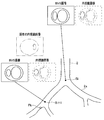
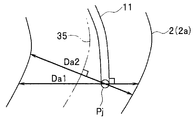
- FIG. 2A is a diagram showing a part of a bronchus and a bronchial shape image.
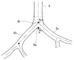
- FIG. 2B is a diagram showing a state in which the diameter of the bronchus is calculated over time after being inserted into the bronchus.
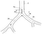
- FIG. 2C is a diagram showing the position where the bronchial diameter is calculated and the size of the calculated bronchial diameter.
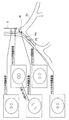
- FIG. 2D is a diagram illustrating candidate information displayed on a monitor when an instruction to perform positioning again is issued.
- FIG. 3A is a diagram illustrating a configuration of an endoscope apparatus including a stereo endoscope that performs stereo measurement.
- FIG. 3A is a diagram illustrating a configuration of an endoscope apparatus including a stereo endoscope that performs stereo measurement.
- FIG. 3A is a diagram illustrating a configuration of an endoscope apparatus including a stereo
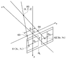
- FIG. 3B is an explanatory diagram illustrating a relationship in which the position of the measurement target for performing stereo measurement is imaged on the imaging surfaces of the left and right imaging elements.
- FIG. 3C is a diagram illustrating an example in which an image obtained by imaging the inside of the bronchus using a stereo endoscope is displayed on a monitor screen.
- FIG. 3D is an explanatory diagram for calculating a bronchial diameter from the image of FIG. 3C.
- FIG. 3E is an explanatory diagram for calculating a bronchus diameter by stereo measurement using a single imaging device.
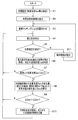
- FIG. 4 is a flowchart showing an example of processing contents in the first embodiment.
- FIG. 5 is an explanatory diagram for obtaining the bronchial diameter.
- FIG. 6 is an explanatory diagram when the bronchial diameter is acquired by a method different from that in FIG. 5.
- FIG. 7 is an explanatory diagram of a position where a bronchial diameter is acquired.
- FIG. 8 is an explanatory diagram of a position where the bronchial diameter is acquired with a setting different from that in FIG.
- FIG. 9 is an explanatory diagram for obtaining a bronchial diameter.
- FIG. 10 is an explanatory diagram when the bronchial diameter is acquired by a method different from that in FIG. 9.
- FIG. 11 is an explanatory diagram when a change in the area of a dark portion in an endoscopic image is detected.
- FIG. 12 is an explanatory diagram when a change in the shape of a branch in an endoscopic image is detected.
- FIG. 13 is an explanatory diagram when a change in the length of a spar in an endoscopic image is detected.
- FIG. 14 is an explanatory diagram when a change in the angle of a spar in an endoscopic image is detected.
- FIG. 15 is an explanatory diagram when a change in the field of view of an endoscopic image is detected.
- FIG. 16 is an explanatory diagram when a change other than a bronchial branch in an endoscopic image is detected.
- FIG. 17 is an explanatory diagram when a change in blurring of a characteristic portion in an endoscopic image is detected.
- the endoscope system 1 As shown in FIG. 1, the endoscope system 1 according to the first embodiment of the present invention is inserted into a bronchus 2 (FIG. 2A) as a predetermined luminal organ in a patient as a subject to be examined.
- An endoscope apparatus 4A provided with an endoscope 3A and an insertion support apparatus 5 that is used together with the endoscope apparatus 4A and that supports the insertion of the endoscope 3A are mainly configured.
- the endoscope apparatus 4A performs signal processing on the endoscope 3A, a light source apparatus 6 that supplies illumination light to the endoscope 3A, and an image sensor 7 that constitutes an imaging unit mounted on the endoscope 3A. It has a camera control unit (abbreviated as CCU) 8A as a signal processing device, and a monitor 9A that displays an endoscopic image generated by the CCU 8A.
- CCU camera control unit
- the endoscope 3 ⁇ / b> A has a flexible elongated insertion portion (or endoscope insertion portion) 11 and an operation portion 12 provided at the rear end of the insertion portion 11.
- the part 13 is provided with an illumination window and an observation window.
- a light guide 14 that transmits illumination light is inserted into the insertion unit 11 and the operation unit 12, and an incident end of the light guide 14 is connected to the light source device 6 and is generated by a light source lamp or LED (not shown) in the light source device 6. The illuminated light is incident on the incident end.
- the illumination light transmitted by the light guide 14 is emitted forward from an emission end (tip surface) attached to the illumination window.
- an objective lens 15 that forms an objective optical system for imaging a subject is attached to the observation window, and an imaging element 7 such as a CCD is disposed at the imaging position.
- An imaging device 16 is formed as an imaging means for imaging the inside of the bronchus 2 as a predetermined luminal organ into which the insertion portion 11 is inserted.
- the image sensor 7 is connected to the CCU 8A via a signal line inserted through the insertion unit 11 and the operation unit 12.
- the CCU 8A generates an image signal of a captured image corresponding to an optical image formed on the imaging surface of the image sensor 7 by an image signal generation circuit (not shown) therein, and outputs the image signal to the monitor 9A.
- the monitor 9A displays the image (moving image) of the image signal as an endoscopic image (also referred to as a captured image).
- the insertion portion 11 of the endoscope 3A is provided with a bendable bending portion 19 at the rear end of the distal end portion 13, and the operator performs an operation of rotating the bending operation knob 20 provided in the operation portion 12, for example.
- the bending portion 19 can be bent in any direction, up and down, left and right.
- the bending operation knob 20 includes an up / down bending operation knob for bending in the up / down direction and a left / right bending operation knob for bending in the left / right direction.
- an endoscope apparatus 4B shown in FIG. 3A may be adopted.
- the endoscope apparatus 4B includes a stereo endoscope 3B capable of three-dimensional measurement (stereo measurement), a light source device 6, and a CCU 8B and a CCU 8B that perform signal processing on the two imaging elements 7a and 7b provided in the stereo endoscope 3B. And a stereo display monitor 9B for displaying the generated stereo image signal.
- Left and right objective lenses 15a and 15b are arranged at a predetermined interval in the left-right direction at the distal end portion 13 of the insertion portion 11 of the stereo endoscope 3B, and the left and right imaging elements 7a and 7b are disposed at respective imaging positions.
- a stereo image pickup device 16 ' having left and right image pickup devices 16a and 16b is arranged.
- the left and right objective lenses 15a and 15b and the left and right imaging devices 16a and 16b have the same characteristics. Further, a light guide 14 that transmits illumination light from the light source device 6 is inserted into the insertion portion 11. The distal end of the light guide 14 is attached to the illumination window of the distal end portion 13, and the transmitted illumination light is emitted from the illumination window to illuminate a subject such as an affected part in the body cavity.
- the left and right imaging elements 7a and 7b that image the illuminated subject are inputted with the photoelectrically converted imaging signals to the imaging control units 18a and 18b in the CCU 8B, and the imaging control units 18a and 18b generate left and right image signals.
- the stereo image signal generator 18c To the stereo image signal generator 18c.
- the stereo image signal generation unit 18c generates a stereo display image signal from the left and right image signals and outputs the stereo display image signal to the stereo display monitor 9B.
- the stereo display monitor 9B displays an image signal for stereo display, and a user such as an operator can stereoscopically view the subject by displaying the image signal for stereo display.
- the left and right image signals generated by the imaging control units 18a and 18b are input to the measurement calculation unit 18d, and the left and right image signals are used for stereo measurement using the principle of triangulation on the captured image.
- the distance between two points can be measured.
- the bronchial diameter Den can be measured.
- Information such as the bronchial diameter Den calculated by the measurement calculation unit 18d is output to the image processing unit 25.
- a video signal generated by the imaging control unit 18 a (or 18 b) is also output to the image processing unit 25.
- various measurements such as the distance between the two points, the distance between the line connecting the two points and the distance between the points, the area, the depth, and the surface shape can be performed. It is also possible to obtain the distance (object distance) from the optical center 63 of the left objective lens 15a or the optical center 64 of the right objective lens 15b to the subject.
- optical data indicating the characteristics of the distal end portion 13 of the endoscope 3B and the objective lenses 15a and 15b is used.
- a plane including both of the two imaging planes is indicated by PL, and the center of the right imaging plane (on the optical axis of the objective lenses 15a and 15b not shown in FIG.
- O L are indicated by O R.
- a method for calculating three-dimensional coordinates from a stereo image there is a method disclosed in Japanese Patent Application Laid-Open No. 2011-027911.
- the measurement point 61 on the image corresponding to one measurement point 60 of the bronchial diameter on the imaging surface in FIG. 3B and The bronchial diameter Den is calculated by designating 62 and a point corresponding to the other measurement point.
- the display screen 71 of the monitor 9B shows a state in which the bronchus 72 in the endoscopic image and the next bronchial bifurcation 73 on the peripheral side of the bronchi 72 are displayed.
- the range of the screen 71 is divided by blocks as indicated by a mesh 74, and an area in which the average luminance in each block is a predetermined value or less is extracted.
- FIG. 3D shows the detection block 75 extracted in this manner with diagonal lines. And the measurement point 60a and the measurement point 60b are set by making the place with the largest diameter of the detection block 75 into the bronchus diameter of a measuring object.
- the measurement points 60a and 60b may be specified in the direction in which the distance between the measurement points 60a and 60b is the largest.
- the above calculation is performed on both the left screen and the right screen constituting the stereo image, and points corresponding to the measurement point 60a and the measurement point 60b are obtained on the left screen and the right screen, respectively. Then, if the point corresponding to the measurement point 60a on the left screen is calculated as the measurement point 61 in FIG. 3B and the measurement point 62 corresponding to the measurement point 60a on the right screen, the position of the measurement point 60 can be obtained. Since the same calculation is performed on the left screen and the right screen corresponding to the measurement point 60b, three-dimensional coordinates corresponding to 60 at both ends of the bronchial diameter can be obtained. Den can be calculated.
- the monocular (single) imaging device 16 of FIG. Stereo measurement may be performed as follows using the provided endoscope 3A.
- the operator bends the bending portion 19 on the distal end side of the insertion portion 11 left and right and picks up images with the left and right imaging devices in FIG. 3B.
- the bronchial diameter may be calculated by stereo measurement.
- the distal end of the insertion portion 11 is set near the center line of the bronchus 2, and the operator curves the bending portion 19, for example, to the left side.
- the objective lens 15 and the imaging element 7 at the first imaging position 16a ′ are indicated by 15a ′ and 7a ′, respectively.
- the surgeon After imaging at the first imaging position 16a ′, the surgeon curves the bending portion 19 to the right, and makes the tip contact the right inner wall of the bronchus 2 as shown by a two-dot chain line in FIG. 3E.
- the second imaging position 16b ′ corresponding to the state of imaging with the right imaging device 16b in FIG. 3B is set.
- the objective lens 15 and the imaging element 7 at the second imaging position 16b ′ are indicated by 15b ′ and 7b ′, respectively. Imaging is performed at the second imaging position 16b '.
- Information such as the number and the pixel pitch is checked in advance and stored in the information recording unit 27 or the like.
- the bending portion 19 is bent by a distance D ′ corresponding to the optical centers 63 ′ and 64 ′ in FIG. 3E corresponding to the left and right optical centers 63 and 64 in FIG. It can be calculated from a corner (or an operation amount of the bending operation knob 20) or the like. Further, the three-dimensional position of the measurement point 60 ′ can be calculated from the information of the measurement points 61 ′ and 62 ′ on the image pickup devices 7a ′ and 7b ′ with respect to the measurement point 60 ′ corresponding to the measurement point 60 in FIG. 3B. Also, the bronchial diameter can be calculated by designating two points, one position of the bronchial diameter and the other position as the measurement point 60 '.
- the bronchial diameter may be calculated using the endoscope 3A of FIG.
- the insertion support device 5 performs CT data as three-dimensional image information of a patient generated by known CT (Computed Tomography) for a patient to be examined by the endoscope 3A or 3B.
- CT data capturing unit 21 for capturing the image data via a portable storage medium such as a DVD, a Blu-ray disc, or a flash memory, and CT as image recording means for recording the CT data captured by the CT data capturing unit 21 And an image data recording unit 22.
- the CT image data recording unit 22 may store CT data generated as a CT (as three-dimensional image information of a patient as a subject) via a communication line, the Internet, or the like.
- the CT image data recording unit 22 can be configured by a hard disk device, a flash memory, a DVD, or the like.
- the CT image data recording unit 22 constituting the image recording means includes a CT image data separated from the CT data and a first coordinate system (CT coordinate system) corresponding to the CT image data separated from the CT data. ) Using the associated image information recording unit 22a that records as associated image information associated with the three-dimensional position data.
- the insertion support device 5 includes a luminal organ extraction circuit as a luminal organ extraction means for extracting three-dimensional image data of the bronchi 2 as a predetermined luminal organ from the CT image data of the CT image data recording unit 22.
- the bronchus extraction part 23 which becomes.
- the bronchus extraction unit 23 obtains 3D shape information (shape data) representing the hollow shape of the bronchus 2 and 3D shape from the extracted 3D data (more specifically, 3D volume data) of the bronchi 2.
- Image information (image data) is generated. That is, the bronchial extraction unit 23 includes a bronchial shape image generation unit 23a as a bronchial shape image generation unit that generates a bronchial shape image 2a as a hollow three-dimensional bronchial shape image from the extracted three-dimensional data of the bronchi 2. Have.
- the bronchi extracting unit 23 extracts the three-dimensional position data in the first coordinate system (or CT coordinate system) corresponding to the three-dimensional data in association with the three-dimensional data.
- the bronchus extraction unit 23 is a correspondence information recording unit 23b including a memory that records correspondence information in which the three-dimensional data of the bronchi 2 (that is, bronchial shape data) and the three-dimensional position data are associated with each other.
- the association image information recording unit 23b records bronchus diameter data at a designated (three-dimensional) position using a lookup table or the like.
- bronchial diameter data corresponding to the designated position can be read from the association information recording unit 23b, and bronchial diameter data can be acquired. Note that the bronchial diameter may be acquired from the bronchial shape data without using the association information recording unit 23b.
- the insertion support device 5 is a virtual endoscope corresponding to an endoscope image generated by imaging of the imaging device 16 or 16a, 16b provided at the distal end portion 13 of the insertion portion 11 in the endoscope 3A or 3B. It has a VBS image generation unit 24 as virtual endoscope image generation means for generating a virtual endoscope image (referred to as a VBS image) as a mirror image.
- VBS image virtual endoscope image generation means for generating a virtual endoscope image (referred to as a VBS image) as a mirror image.
- characteristic information including an imaging system related to the imaging device 16 at the distal end portion 13 of the endoscope 3A is, for example, Input from the input device 31 via the control unit 26.
- characteristic information regarding the imaging device 16 may be input from the input device 31 to the VBS image generation unit 24 without going through the control unit 26.
- the VBS image generation unit 24 is a three-dimensional position of the imaging device 16 (also referred to as the three-dimensional position of the distal end of the insertion unit 11) arranged in the distal end portion 13 of the endoscope 3A actually inserted into the bronchus 2. Based on the information, the characteristic information for imaging the subject in the bronchus 2 by the imaging device 16, and the bronchial shape data, the inside of the bronchus 2 is endoscopically set with the three-dimensional position (also simply referred to as position) as the viewpoint position. A VBS image for virtually drawing the captured endoscopic image is generated.
- the VBS image generation unit 24 can generate a VBS image corresponding to the change. Therefore, for example, when the position of the distal end of the insertion unit 11 and the (axis) direction of the distal end are designated by the CT coordinate system, the VBS image generation unit 24 generates a VBS image corresponding to the designation of the position and direction.
- the insertion support device 5 controls the image processing unit 25, the image processing unit 25, and the like that align the endoscope image input from the CCU 8A and the VBS image of the VBS image generation unit 24 by image matching.
- a control unit 26 as a control unit to perform and an information recording unit 27 constituting an information recording unit that records predetermined information such as a VBS image for supporting insertion under the control of the control unit 26 as candidate information.
- the insertion support apparatus 5 includes an MPR image generation unit 28 that generates a CT tomographic image (referred to as an MPR image) as a multi-section reconstruction image based on the CT image data recorded in the CT image data recording unit 22, and an MPR image.
- the path setting unit 29 determines the target from the insertion start position (of the insertion unit 11) in the bronchi 2 from the CT image data and the bronchial shape image 2a. It has a function of a route data generation unit 29a that generates route data to a target position in the vicinity of the part 36.
- the endoscope system 1 further includes an input device 31 including a keyboard and a pointing device for inputting setting information to the route setting unit 29. Further, the surgeon can input parameters and data when performing image processing from the input device 31 to the image processing unit 25, and can select and instruct the control operation to the control unit 26. .
- the route setting unit 29 sends information on the set route to the VBS image generation unit 24, the MPR image generation unit 28, and the control unit 26.
- the VBS image generation unit 24 and the MPR image generation unit 28 generate a VBS image and an MPR image along the route, respectively, and the control unit 26 controls the operation of each unit along the route.
- the image processing unit 25 receives an endoscopic image (also referred to as an actual image or simply an image) generated by the CCU 8A and a VBS image generated by the VBS image generation unit 24.
- the bronchial shape image 2a generated by the bronchial shape image generating unit 23a is also input to the image processing unit 25.
- the alignment processing unit 25a by the image processing unit 25 is installed.
- the three-dimensional position (position) of the distal end of the insertion portion 11 is estimated (or calculated) by image matching at.
- a three-dimensional position (known position) that can be specified from the bronchial shape image 2a by the CT coordinate system, such as the entrance of the bronchus 2 or the carina K (see FIG. 2A), or its neighboring position is set as a moving image matching start position.
- the VBS image generation unit generates a VBS image based on the position information.
- the alignment processing unit 25a of the image processing unit 25 is a three-dimensional position (a known position) that can be specified from the bronchial shape image 2a by the CT coordinate system (first coordinate system), such as the entrance of the bronchus 2 or a carina, or the vicinity thereof.
- the distal end of the insertion portion 11 is set at the position, and a state where the position of the distal end of the insertion portion 11 can be estimated (or calculated) by the CT coordinate system is set.
- the alignment processing unit 25a of the image processing unit 25 compares the endoscopic image and the VBS image, and a condition in which the comparison result is set (an error that can ensure a predetermined accuracy). Start matching image within. Therefore, the image processing unit 25 includes an image comparison unit 25b as an image comparison unit that compares the endoscopic image and the VBS image, and the alignment processing unit 25a uses image comparison performed by the image comparison unit 25b. To perform alignment processing by image matching.
- the alignment processing unit 25a of the image processing unit 25 calculates the position of the distal end of the insertion unit 11 and the axial direction of the distal end (the viewpoint direction or the line-of-sight direction of the imaging device 16).
- a state in which the position coordinates in the coordinate system (first coordinate system) and information indicating the axial direction (also referred to as posture) can be specified (acquired) is set.
- the position of the distal end of the insertion unit 11 thereafter is determined by the CT coordinate system (first coordinate system) based on the image comparison result by the image comparison unit 25b using the registered information. It becomes possible to obtain as information associated with the position at. That is, the image processing unit 25 includes a position estimation unit 25c that acquires the position of the distal end of the insertion unit 11 by estimation as a position information acquisition unit that acquires the position (information) of the distal end of the insertion unit 11. The position estimation unit 25c also acquires the position of the tip of the insertion unit 11 based on the image comparison result by the image comparison unit 25b.
- the image processing unit 25 is inserted under the CT coordinate system in the state after the alignment by the alignment processing unit 25a in the operation of inserting the insertion unit 11 into the deep side (peripheral side) of the bronchus 2.
- the position where the tip of the part 11 has moved is estimated from the comparison result of both the endoscopic image and the VBS image.
- the position estimation unit 25c uses the VBS image (output from the VBS image generation unit 24) when the distal end of the insertion unit 11 is moved on a path substantially along the core line 35, and the current endoscopic image. Is selected by image processing, and the three-dimensional position corresponding to the selected VBS image is calculated (estimated) as the position of the tip of the insertion unit 11. As described above, the position estimation unit 25 c calculates (estimates) the posture of the insertion unit 11 as well as the position of the distal end.
- the distal end of the insertion unit 11 may be moved at a position deviated from the core wire 35. Therefore, the VBS image generation unit 24 generates a VBS image at a position eccentric from the core wire 35 by an appropriate distance.
- the processed VBS image may be output to the alignment processing unit 25a. In this way, the range of position estimation by image matching can be expanded.
- the movement amount of the distal end of the insertion unit 11 and the moved position are calculated (estimated) from the difference amount between the two positions estimated by the position estimation unit 25c.
- the position estimation unit 25c calculates (estimates) a distance between the estimated position and a specific position such as a branch point (a position that can be specified by the CT coordinate system) in the feature region of the bronchus 2. You can also For this reason, the position estimation unit 25c determines the position of the distal end of the insertion unit 11 estimated by the position estimation unit 25c and a feature region such as a branched region in the bronchus 2 as a predetermined luminal organ. It has a function of a distance calculation unit as a distance calculation means for calculating the distance.
- the image processing unit 25 has a function of the position estimation unit 25c as a position information acquisition unit that acquires information on the position of the distal end of the insertion unit 11 by estimation.
- the alignment processing unit 25a may be defined as a configuration including the function of the position estimation unit 25c.
- the distal end of the insertion portion 11 is used in the same meaning as the distal end of the endoscope 3A.
- the image processing unit 25 generates an image to be displayed on the monitor 32 as an image display unit under the control of the display control unit 26 a that controls display in the control unit 26.
- the image processing unit 25 normally outputs an image signal (video signal) of the bronchial shape image 2a generated by the bronchial shape image generation unit 23a to the monitor 32.
- the bronchial shape image 2a is displayed on the monitor 32 as a two-dimensional tomographic image cut out in a cross section along the direction passing through the center of the lumen, for example.
- the display is not limited to a two-dimensional tomographic image, and a three-dimensional image may be displayed.
- a three-dimensional image for example, it may be displayed in a projection view by a parallel projection method or in a perspective view so that the inside of the lumen can be seen.
- a core line 35 passing through the center of the lumen of the bronchus 2 is also displayed on the bronchial shape image 2 a displayed on the monitor 32.
- the core wire 35 is generated by, for example, the bronchial shape image generation unit 23a, but the image processing unit 25 may generate the core wire 35.
- the image processing unit 25 has a function of an image generation unit 25d that generates an image or the like that superimposes the position of the distal end of the insertion unit 11 estimated by the position estimation unit 25c together with the core wire 35 on the bronchial shape image 2a. .
- the core wire 35 and the position of the distal end of the insertion portion 11 are displayed on the bronchial shape image 2 a representing the three-dimensional shape of the bronchus 2.
- the insertion operation of the insertion portion 11 can be easily performed by referring to the display. Further, by performing an operation of inserting along the core wire 35, the position of the distal end of the insertion portion 11 by image matching can be estimated in a short time. Further, the image processing unit 25 detects a change amount of the lumen diameter of a predetermined lumen organ based on the position information of the tip of the insertion unit 11 estimated by the position estimation unit 25c. As a means, a bronchial diameter change detection unit 25e that detects a change in bronchial diameter (in the case of bronchi 2 as a predetermined luminal organ) is provided.
- the bronchial diameter change amount detection unit 25e includes a bronchial diameter acquisition unit as a bronchial diameter acquisition unit that acquires the bronchial diameter from the CT coordinate system corresponding to the current tip position of the insertion unit 11 estimated by the position estimation unit 25c.
- the function of the bronchial diameter comparing unit as a bronchial diameter comparing means for comparing the bronchial diameter acquired by the bronchial diameter acquiring unit with a preset reference bronchial diameter is provided.
- the bronchial diameter acquisition unit detects the amount of change, that is, the amount of change in the bronchial diameter, by sequentially acquiring the bronchial diameter at each position of the estimated tip of the insertion unit 11 during the insertion operation of the insertion unit 11. .
- the bronchial diameter comparison unit compares the current bronchial diameter acquired sequentially with the reference bronchial diameter.
- the case where the current bronchus diameter is smaller than the reference bronchus diameter is set as a first condition for recording predetermined information including a VBS image.
- the image processing unit 25 is an image change as an image change amount detection unit that detects a change amount of a feature portion in an endoscopic image (also simply referred to as an image) captured by the image capturing device 16. It has the quantity detection part 25g.
- the present embodiment includes the bronchial diameter change amount detection unit 25e as the first change amount detection unit and the image change amount detection unit 25g as the second change amount detection unit.
- the bronchial diameter change amount detection unit 25e as the first change amount detection means is used for detection (determination) as to whether or not the first condition is satisfied.
- the image change amount detection unit 25g as the second change amount detection unit satisfies the second condition of whether or not the change amount of the characteristic part in the endoscopic image is larger than the set value ⁇ Dth. Used to detect In this embodiment, in a state where the first condition is satisfied, information including the VBS image is recorded when the second condition is satisfied (a predetermined condition is satisfied).
- the image change amount detection unit 25g is a bronchial diameter change amount detection unit 25h that detects a change amount of the bronchial diameter (inner diameter of the bronchus 2) as a feature portion, a brightness change amount in the branch region, or a feature region in the branch region.
- a brightness change amount detection unit 25i that detects a change amount of brightness
- a shape change amount detection unit 25j that detects a shape change amount in a branch region or a shape change amount of a feature portion in a branch region.
- the shape change amount detection unit 25j detects the amount of change in the length or angle of a spar (branch point or branch boundary) where the lumen of the bronchus 2 diverges (branches) as the shape change amount of the branch region (characteristic portion).
- the brightness change amount detector 25i has a function of a visual field defect detector 25l described later. The present invention is not limited to the case where the brightness change amount detection unit 25i has the function of the visual field defect detection unit 25l.
- the control unit 26 generates the route data generated by the route data generation unit 29a (before insertion of the insertion unit 11 of the endoscope 3A) based on the position of the distal end of the insertion unit 11 estimated by the position estimation unit 25c. You may make it correct
- control unit 26 determines whether or not a detection result by the bronchial diameter change detection unit 25e and a detection result by the image change detection unit 25g satisfy a predetermined condition for recording. It has the function of.
- condition determination unit 26b in the control unit 26 determines that the predetermined condition is satisfied, information on the position and orientation of the distal end of the insertion unit 11 estimated by the position estimation unit 25c when it is determined that the predetermined condition is satisfied.
- the information recording unit 27 records predetermined information in association with the VBS image corresponding to the position and orientation information, that is, position and image information (as candidate information to be presented at the time of realignment).
- the information recording unit 27 is based on the detection result by the bronchial diameter change amount detection unit 25e and the detection result by the image change amount detection unit 25g, and information on the position and orientation of the distal end of the insertion unit 11 and the position. And a function of information recording means for recording predetermined information as candidate information associated with the VBS image corresponding to the posture information.
- the condition determination unit 26b of the control unit 26 has a function of an information recording control unit 26c as an information recording control unit that performs control to record predetermined information in the information recording unit 27.
- the information recording control unit 26c has a bronchial diameter detected by a bronchial diameter change detecting unit 25e serving as a lumen diameter change detecting unit that is smaller than a reference bronchus diameter and is detected by the image change detecting unit 25g.
- the information recording unit 27 controls to record predetermined information including the VBS image.
- the condition determination unit 26b in the control unit 26 determines whether or not the detection result by the bronchial diameter change detection unit 25e and the detection result by the image change detection unit 25g satisfy a predetermined condition for recording. Instead of performing the determination, it may be determined whether or not the bronchial diameter change amount detection unit 25e and the image change amount detection unit 25g satisfy the first condition and the second condition, respectively. For this reason, the image processing unit 25 may have the function of the condition determination unit 26b.
- the display control unit 26a of the control unit 26 is used to perform input again in order to perform alignment again, for example, when the operator thinks that the accuracy of the estimated position of the distal end of the current insertion unit 11 is low.
- predetermined information recorded in the information recording unit 27 is read and displayed as candidate information on the monitor 32 via the image processing unit 25. Control to do.
- the image processing unit 25 includes an image generation unit 25d that generates an image to be displayed by superimposing the candidate information read from the information recording unit 27 on the bronchial shape image 2a. Specifically, the position and posture of the distal end of the insertion unit 11 and the VBS image corresponding to the position and posture are superimposed and displayed on the bronchial shape image 2a. As will be described later, FIG. 2D displays the position of the distal end of the insertion portion 11 on the bronchial shape image 2a displayed on the monitor 32 at a position corresponding to the position, and a VBS image corresponding to the position. A state of being superimposed and displayed in association with the position (by a line) is shown.
- the surgeon performs positioning again with reference to the candidate information, and the positioning processing unit 25a or the position estimating unit 25c determines the position and posture information of the distal end of the insertion unit 11 in the coordinate system of the bronchus 2 (CT coordinate system). ) Can be obtained in a state of being associated with. Then, by re-alignment, the position estimation unit 25c can perform an operation of ensuring the predetermined accuracy and reinserting the distal end of the insertion unit 11 into the deep side of the bronchus 2 from the re-aligned position. .
- the detection result by the bronchial diameter variation detection unit 25e satisfies the first condition
- the detection result by the image variation detection unit 25g satisfies the second condition (that is, the first condition).
- the position and orientation of the distal end of the insertion portion 11 when the determination result is obtained (estimated)
- the position and orientation Predetermined information including the corresponding VBS image is recorded in the information recording unit 27 as candidate information.
- predetermined information serving as candidate information may be recorded in the information recording unit 27 so as to include at least the position and the position of the tip.
- predetermined information also simply referred to as information
- an appropriate amount (or number) of candidate information is displayed. Can be displayed (or presented) on the monitor 32.
- the image change amount detection unit 25g detects a change amount of a characteristic part such as a bronchus diameter related to the bronchus 2 as a predetermined luminal organ in an endoscopic image captured by the imaging device 16, and at least the Based on the detection result by the image change amount detection unit 25g, predetermined information including the position and posture (information) at the distal end of the insertion unit 11 at the time of the detection result and the VBS image corresponding to the position and posture.
- the information is recorded in the information recording unit 27 (as candidate information to be presented when realignment is performed).
- a user such as a surgeon easily grasps conditions or conditions for recording information in order to perform an operation of inserting the insertion unit 11 while observing an endoscopic image captured by the imaging device 16.
- the candidate information presented when re-alignment is performed is set such that the amount of change in the feature in the endoscopic image changes sensitively to the movement of the position of the tip of the insertion unit 11. Therefore, it is easy to perform alignment by image comparison.
- the information recorded in the information recording unit 27 includes the position and orientation of the distal end of the insertion unit 11 and the corresponding VBS image, and further includes an endoscopic image corresponding to the position and orientation information. It may be recorded.
- the image processing unit 25 temporarily stores the endoscopic image and the VBS image when performing image matching by comparing both the endoscopic image and the VBS image, or the image processing work area.
- An image memory 26f used as An image memory 25f may be provided outside the image processing unit 25.
- the input device 31 includes a first condition relating to a change amount of the inner diameter of the bronchus 2 detected by the bronchial diameter change amount detection unit 25e and a change in the characteristic portion detected by the image change amount detection unit 25g. You may make it the structure which has the designation
- the information recording unit 27 records the predetermined information (position and image information) serving as the candidate information described above, as well as the condition information of the first condition and the condition information of the second condition regarding the second condition It may be possible to have a condition information recording unit 27a that records in advance.
- the condition recording unit 27a may be provided separately from the information recording unit 27.
- the condition information of the first condition includes (a) the difference (change amount) between the preset reference bronchus diameter Dre and the current bronchial diameter Da (at the distal end of the insertion portion 11), (b ′) This is the difference (change amount) between the reference bronchial diameter Dre and the current bronchial diameter at the reference position set by the user.
- (b ′) is further subdivided, (b) the difference (change amount) between the bronchial diameter Dre of the bifurcation portion having the preset number of branches and the current bronchial diameter Da, (c) any position set by the user Difference (change amount) between the reference bronchus diameter Dre and the current bronchus diameter Da at (d), (d) the reference bronchus diameter Dre and the current bronchus at the position of the endoscope tip having a preset endoscope insertion length It is good also as a difference (change amount) of diameter Da.
- the condition information of the second condition includes (a) a change in the bronchial diameter (bronchial diameter calculated from the endoscopic image) Den in the endoscopic image, and (b) a display for displaying the endoscopic image or the endoscopic image. (C) a change in the shape of the branch in the endoscopic image, (d) a change in the length of the spar in the endoscopic image, (e) a change in the angle of the spar in the endoscopic image, ( f) poor visual field (in the endoscopic image), (g) large blurring of the endoscopic image, (h) changes such as other than bronchi appearing in the endoscopic image.
- a user such as an operator can select, for example, from the condition information of the first condition (a) to (d) and the condition information of the second condition (a) to (h) (for example, the input device 31). It may be possible to selectively specify from the specifying unit 31a.
- the control unit 26 has a function of a condition setting unit 26d that sets the first condition and the second condition in response to the designation by the designation unit 31a.
- the condition setting unit 26d may also set threshold information and the like used when the condition determination unit 26b makes a determination when setting the first condition and the second condition.
- the threshold information may also be recorded in the information recording unit 27 in association with the information on the first condition and the second condition. Further, only the condition information of one condition (for example, the second condition) in the information of the first condition and the second condition may be recorded in the condition information recording unit 27a.
- the position estimation unit 25c as the position information acquisition unit means fails to acquire the position information of the tip of the insertion unit 11 based on the comparison result of the image comparison unit 25b, or in the information recording unit 27
- an instruction signal for causing the recorded predetermined information to be presented as candidate information is generated, the position of the distal end of the insertion unit 11 in the predetermined information recorded in the information recording unit 27 in the bronchial shape image 2a
- a display control unit 26a for controlling to display a VBS image corresponding to the position of the tip, and the position estimation unit 25c or the alignment processing unit 25a from the information recording unit 27.
- the image processing unit 25 can be configured by a CPU (Central Processing Unit), but the alignment processing unit 25a to the image change amount detection unit 25g inside the image processing unit 25 are each other than the CPU. It may be configured by using dedicated hardware. Also, the control unit 26 in FIG. 1 may be configured by a CPU, or may be configured by using dedicated hardware other than the CPU.
- CPU Central Processing Unit
- the endoscope system 1 having such a configuration includes a CT image data recording unit 22 as an image recording unit that records three-dimensional image information in a subject acquired in advance, and a predetermined luminal organ from the three-dimensional image information.
- a bronchus extraction unit 23 as a luminal organ extracting means for extracting the bronchus 2 and the information on the predetermined luminal organ extracted by the luminal organ extracting means endoscopically from a predetermined viewpoint position.
- VBS image generation unit 24 as a virtual endoscopic image generation unit that generates a drawn virtual endoscopic image
- an imaging unit that is provided in the endoscope 3A or 3B and images the inside of the predetermined lumen organ
- the endoscope 3A Is a bronchial diameter change amount detection unit as a luminal diameter change amount detecting means for detecting the change amount of the luminal diameter of the bronchus 2 as the predetermined luminal organ based on the position information of the tip of the 3B insertion unit 11 25e, and an image change amount detection unit 25g as an image change amount detection unit that detects a change amount of the characteristic part related to the bronchus 2 as the predetermined luminal organ in the endoscopic image picked up by the image pickup unit; Based on the detection result of the lumen diameter change amount detection unit and
- FIG. 4 shows a typical process in this embodiment.
- the process in FIG. 4 starts.
- Initial setting processing is performed in the first step S1 in FIG.
- the surgeon inputs information used for insertion support in the present embodiment from the input device 31.
- the surgeon designates the first condition and the second condition from the designation unit 31a.
- the condition determination part 26b will be in the state which performs determination corresponding to the designated 1st condition and 2nd condition.
- the operator designates, as the first condition, (a) the difference between the preset bronchial diameter (reference bronchial diameter) Dre and the current bronchial diameter Da, and the second condition is the bronchial diameter in the endoscopic image.
- the case where the change of Den is designated will be described below as (A).
- the reference bronchial diameter Dre information is not recorded at an insertion site that does not require recording, for example, near the entrance of the bronchus 2, and desired information can be stored at the insertion site that the operator desires to record. To be able to record.
- the diameter of the bronchus is large at the insertion site such as the vicinity of the entrance of the bronchus 2 and the operator can easily operate as intended by the insertion unit 11. It's easy to figure out where you are. Further, since the region is in the vicinity of the position where the first alignment is performed, the position of the distal end of the insertion portion 11 can be estimated with high accuracy.
- the operation of inserting the insertion portion 11 becomes difficult, and the bronchus 2 also becomes thin, so that it tends to be difficult to understand where the tip position is in the bronchus 2.
- the luminal region is located at a distance away from the first aligned position, the accuracy of the position estimation tends to decrease. Therefore, the surgeon may desire information used as candidate information for performing realignment.
- the operator sets a reference bronchial diameter Dre corresponding to the bronchial diameter at the site desired to be recorded. As will be described later, it is possible to record only predetermined information that is effective candidate information that facilitates re-alignment in a luminal region that the operator desires to record.
- the endoscopic image is used when re-alignment is performed by comparing the images.
- An image portion having a large change amount in the mirror image can be set as a main comparison target portion. Then, by setting a comparison target portion having a large change amount, it is easy to visually perform re-alignment by image comparison and can be completed in a short time.
- the bronchial shape image generation unit 23a in step S2 determines the bronchial shape as a shape image of the bronchus 2 as shown in FIG. An image 2a is generated.
- the bronchial shape image 2a is output to the monitor 32 via the image processing unit 25, and the bronchial shape image 2a is displayed on the monitor 32 as shown in FIG. 2A.
- the core line 35 passing through the center of the lumen of the bronchus 2 is displayed on the bronchial shape image 2a.
- Each position of the core line 35 and the branch point Bi is a known three-dimensional position specified in the CT coordinate system.
- the operator inserts the insertion portion 11 of the endoscope 3A into the bronchus 2.
- the surgeon uses the image comparison unit 25b at a known position such as the entrance of the bronchus 2 to set the condition (predetermined) that the endoscopic image by the imaging device 16 (or 16 ′) and the VBS image are set. Alignment processing by image matching is performed so that they match within an error that can ensure the accuracy of (1).
- the imaging device 16 ′ one endoscopic image obtained by one imaging device 16a or 16b in the imaging device 16 ′ may be employed. Note that the order of steps S2 and S3 may be switched or performed in parallel.
- step S4 the operator inserts the distal end of the insertion portion 11 closer to the deeper side of the bronchus 2 than the aligned position.
- the position estimation unit 25c of the image processing unit 25 uses the image comparison unit 25b to determine the position and orientation of the tip of the insertion unit 11 at a fixed time interval or the like. It is determined whether or not the estimation is successful by matching.
- the estimated position and posture of the distal end of the insertion section 11 are acquired as shown in step S6, and the bronchial diameter Da corresponding to the (current) position of the distal end of the insertion section 11 is acquired. Is obtained (from the CT image data recording unit 22 or the bronchi extraction unit 23). These pieces of information are temporarily stored in the image memory 25f, for example, and referred to when necessary in the processing in FIG. Note that the bronchial diameter Den may also be calculated from the endoscopic image at the time of estimating the position and posture of the distal end of the insertion section 11 in step S6. Further, the estimated position of the distal end of the insertion portion 11 is displayed on the bronchial shape image 2a. As shown in FIG. 2A, the estimated position Pj is displayed at the corresponding position on the bronchial shape image 2a.
- step S7 after step S6, the bronchial diameter change amount detection unit 25e or the condition determination unit 26b of the control unit 26 determines whether or not the bronchial diameter Da acquired in step S5 is smaller than a preset reference bronchial diameter Dre. I do. If the acquired current bronchus diameter Da is not smaller than the reference bronchus diameter Dre, the process returns to step S4, and the operator inserts the insertion portion 11 into the deep side. On the other hand, if the acquired bronchial diameter Da is smaller than the reference bronchial diameter Dre in the determination process of step S7 in FIG. 4, the image change amount detection unit 25g (the bronchial diameter change amount detection unit 25h) in the next step S8.
- Detects (calculates) a change amount (difference) ⁇ Den of the bronchial diameter Den calculated from the endoscopic image. That is, the image change amount detection unit 25g calculates the bronchial diameter Den calculated from the endoscopic image at the current distal end position of the insertion unit 11 and the endoscopic image at the previously estimated distal end position of the insertion unit 11. The amount of change ⁇ Den from the calculated bronchial diameter Den is calculated.
- the bronchial diameter Den calculated from the endoscopic image is not an average value of the lumen of the bronchus 2 but includes a case of a non-circular shape spreading in the branching direction at the branching portion. For this reason, the bronchial diameter Den calculated from the endoscopic image may be larger than the reference bronchus diameter Dre that is almost circular in the lumen of the bronchus 2.
- the condition determination unit 26b of the control unit 26 determines whether or not the change amount ⁇ Den of the bronchial diameter is larger than the set value ⁇ Dth. If the change amount ⁇ Den of the bronchial diameter is not larger than the set value ⁇ Dth, the process returns to step S4.
- step S10 the condition determination unit 26b determines the position and posture of the distal end of the insertion unit 11 corresponding to the determination result of step S9.
- Predetermined information with the VBS image corresponding to the position and orientation is recorded in the information recording unit 27.
- step S9 instead of determining whether or not the bronchial diameter change amount ⁇ Den is greater than the set value ⁇ Dth, it may be determined whether or not the bronchial diameter change amount ⁇ Den is greater than or equal to the set value ⁇ Dth. .
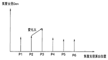
- the bronchial diameter Den is acquired from the endoscopic image together with the position estimation. Shows how it was done.
- the estimated position Pj moves through the positions P1, P2,..., P6 as the current tip position P7.
- each position Pj indicated by a white circle in FIG. 2B is a position satisfying the first condition (step S7), and a position P7 indicated by a black circle is the current position.
- the outline of the change in the bronchial diameter Den calculated by the measurement calculation unit 18d and the like at each position Pj described above is as shown in FIG. 2B, and FIG.
- the positions P1 to P6 where the bronchial diameter Den is calculated and the state of change of the calculated bronchial diameter Den are shown.
- Information acquired at each of the positions P1 to P6 is temporarily stored in the image memory 25f or the like and used for comparison.
- the bronchial diameter Den greatly changes so that the bronchial diameter Den becomes a peak near the branch point Bi.
- the condition determination unit 26b provides, as information (candidate information), predetermined information with, for example, the position and orientation of the position P3 and the VBS image corresponding to the position and orientation of P3 when the position P2 changes to the position P3 Records in the recording unit 27.
- the bronchial diameter Den also changes from a large value to a small value when the position changes from the position P3 to the position P4, but is not recorded at the position P4 because it is recorded at the position P3.
- the information recording unit 27 responds with information on the position and orientation between P2 and P3.
- Information with the VBS image to be recorded may be recorded.
- the position P3 substantially the position of the branch point Bi
- information may be set to be selectively recorded in the vicinity of the position where the bronchial diameter Den is maximum or peak in the endoscopic image.
- the candidate information is presented, and the change in the portion corresponding to the bronchial diameter Den in the endoscopic image when the distal end of the insertion portion 11 is moved for realignment is large. It is easy to perform alignment by image comparison (candidate information in FIG. 2D described below corresponds to an example in which information is recorded in the vicinity of the branch points Bi and Bi + 1 where the bronchial diameter Den is maximum or peak).
- the operator pays attention to the bronchial diameter Den portion in the endoscopic image and adjusts the position and posture of the distal end of the insertion portion 11 so that the bronchial diameter Den portion is maximized.
- the adjustment content (adjustment policy) becomes clear as if it is easy to grasp the part of interest and that the value is adjusted to the maximum, so image matching ( It becomes easy to perform alignment by (image comparison).
- the portion to be noted is not clear, and the orientation of how to adjust the change in the position and posture of the distal end of the insertion portion 11 is also unclear. Takes time to align. If the movement distance from the aligned position is small by the alignment in step S3 described above, the position estimation unit 25c can perform position estimation with relatively high accuracy. However, if the movement distance increases, The accuracy of estimation may be reduced.
- step S5 If the position estimation is not successful in step S5, the display control unit 26a of the control unit 26 reads predetermined information recorded in the information recording unit 27 and sends it to the image processing unit 25 in step S11.
- the image processing unit 25 outputs an image signal of the presentation information to the monitor 32, and the monitor 32 presents candidate information. Then, the process returns to step S3.
- step S ⁇ b> 3 the surgeon performs alignment again with reference to the candidate information displayed on the monitor 32. After performing the alignment again, the process of FIG. 4 is repeated. In this way, the operation of inserting the insertion portion 11 into the distal side (deep side) of the bronchus 2 can be performed smoothly.
- FIG. 2D shows a display example of candidate information in the case of step S11. In the candidate information display example of FIG.
- the branch points Bi and Bi + 1 and the corresponding VBS images are displayed, for example, by connecting them with lines, and the branch point Bi-1 etc. on the trunk side (insertion side) with respect to the branch point Bi is also the same. You may display.
- predetermined information recorded in the vicinity of branch points Bi and Bi + 1 where the lumen that is a characteristic region in the bronchus 2 branches is displayed as candidate information in the case of realignment.
- candidate information narrowed down to the minimum necessary in the vicinity of each branch point suitable for re-alignment is displayed. Therefore, it becomes easy for the surgeon to perform the positioning again smoothly and in a short time.
- the information to be recorded is narrowed down according to the first condition and the second condition, it is possible to record predetermined information having an information amount suitable for performing re-alignment.
- FIG. 2D predetermined information recorded in the vicinity of branch points Bi and Bi + 1 where the lumen that is a characteristic region in the bronchus 2 branches is displayed as candidate information in the case of realignment.
- the candidate information displayed at the time of re-alignment is too much or insufficient, and the appropriate position is re-positioned. It takes time to make adjustments.
- information is recorded when the feature portion in the endoscopic image changes greatly with respect to the movement of the position of the distal end of the insertion portion 11, so that a user such as an operator can record the information. Is easy to grasp the conditions for recording information. Therefore, this embodiment can record predetermined information having an information amount suitable for performing re-alignment under conditions that are easy for the user to visually grasp.
- the feature portion in the endoscopic image with respect to the movement of the position of the distal end of the insertion portion 11 This reflects the characteristic that changes greatly, so that it becomes easier for the user to visually perform re-alignment by image matching.
- the current endoscopic image is read from the information recording unit 27 and displayed together with the VBS image (and endoscopic image) as candidate information to be displayed, as shown by a two-dot chain line in FIG. 2D. You may make it display as a synthesized image superimposed on the shape image 2a. Thus, when the current endoscopic image is displayed adjacent to the candidate information, it is possible to easily perform alignment by image comparison with the candidate information.
- the display position can be moved so that the VBS image on the candidate information side is superimposed on the display position of the current endoscopic image, or the endoscopic image on the candidate information side is displayed on the current endoscopic image.
- An image moving unit that allows the display position to be moved so as to overlap the position may be provided in the image processing unit 25.
- the current endoscopic image display position is configured to include an image moving unit that can be moved to the candidate information side VBS image display position or the candidate information side endoscopic image display position. Also good.
- the bronchial diameter change amount detection unit 25e acquires the bronchial diameter Da based on information on the position of the distal end of the insertion unit 11, it may be acquired by the method shown in FIGS.
- the bronchial diameter Da1 calculated from the lumen of the bronchus 2 on the plane perpendicular to the longitudinal direction (or axial direction) of the distal end of the insertion portion 11 is employed as shown in FIG.
- the bronchial diameter Da2 calculated along a plane perpendicular to the core wire 35 so as to include the distal end of the insertion portion 11 and a perpendicular extending from the distal end to the core wire 35 may be employed.
- the bronchial diameter variation detection unit 25e detects the variation in the lumen diameter of the predetermined luminal organ in a plane perpendicular to the longitudinal direction of the distal end based on the information on the position of the distal end of the insertion unit 11.
- the amount of change in the lumen diameter of the predetermined lumen organ in a plane perpendicular to the core line 35 that is the center line of the lumen of the bronchus 2 may be detected.
- the reference bronchial diameter Dre used for the first condition is set to one regardless of the patient.
- Set bronchial diameter for the purpose of setting an optimal reference bronchus diameter for each patient.
- the surgeon decides in advance the number of branches that should be recorded as candidate information to be referred to.
- the number of branches is identification information that is easily identified by numbering sequentially according to the order of the branching portions as portions where the lumen branches from the entrance in the bronchus.
- the bronchus diameter corresponding to the number of branches set in advance by the operator is calculated from the three-dimensional data of the bronchus extraction unit 23 or the CT image data recording unit 22, and the calculated bronchial diameter is set as the reference bronchial diameter Dre. After this setting, the same operation as the case (case) of (A) is performed using the set reference bronchial diameter Dre.
- the reference bronchus diameter Dre can be set according to the actual patient's bronchi. For this reason, even in the case of patients having different physiques, the reference bronchus diameter Dre corresponding to the bronchus of the patient into which the insertion portion 11 is actually inserted can be set appropriately. Further, the reference bronchus diameter Dre corresponding to the bronchus diameter at the position where the operator actually wants to record the candidate information can be set with high accuracy. Therefore, it is possible to record only effective information that is candidate information desired by the surgeon without wastefully recording information that does not require recording.
- one reference bronchus diameter Dre may be set and a condition for recording a bronchus diameter smaller than this value may be set. May be set, a second reference bronchus diameter may be set.
- the bronchial diameter Dre1 may be set to satisfy the bronchial diameter between the two reference bronchial diameters Dre0 and Dre1 as a condition for recording.
- a lower limit reference bronchus diameter is set, and the calculated current bronchus diameter Da is set to the lower limit side.
- the diameter of the bronchus is smaller than the reference bronchus diameter, it may be determined that the target lumen portion has been inserted and the recording operation may be terminated. Moreover, you may make it use the order by which the name is decided for every branch anatomically instead of the number of branches mentioned above.
- the position to be detected is a branch point on the core wire 35 as shown in FIG. It may be set near the position of Bi or Spur Spi. Alternatively, as indicated by a dotted line, the area may be limited to a radius Ra, Rb around the branch point Bi or the spur Spi. When such a region is set, it may be set for each branch point Bi or spur Spi. Also, unlike FIG. 7, as shown in FIG.
- the core 35 is a distance Pa from the bifurcation point Bi along the direction of the core 35 along the direction of the core 35 and returned to the entrance (basic) side of the bronchus 2 or a distance da from the spar Spi.
- the bronchial diameter Da1 along a plane perpendicular to the axial direction of the distal end of the insertion portion 11 as shown in FIGS. 9 and 10.
- the bronchial diameter Da2 along the plane perpendicular to the core line 35 or the bronchial diameter Da3 along the coordinate axis of the three-dimensional data in the CT coordinate system may be used.
- the maximum value / minimum value of the corresponding bronchus 2 only the right lung, only the left lung, both lungs, or only on the insertion path of the preset insertion unit 11 may be used. good.
- the bronchial diameter is calculated by the bronchial diameter Da1 along the plane perpendicular to the axial direction of the distal end of the insertion portion 11, the bronchial diameter Da2 along the plane perpendicular to the core 35, and CT.
- the bronchial diameter Da3 along the coordinate axis of the three-dimensional data in the coordinate system may be used.
- the case (C) has almost the same effect as the case (B).
- (D) Bronchial diameter Dre at the position of the distal end of the insertion portion 11 having a preset insertion length The surgeon sets the insertion length (endoscope insertion length) of the insertion unit 11 for which it is better to acquire candidate information in advance from the input device 31, and for example, distance estimation included in the position estimation unit 25c of the image processing unit 25 All the positions in the bronchus 2 that can be reached with the insertion length set in the three-dimensional data of the CT image data recording unit 22 or the bronchi extracting unit 23 are calculated by the function of the unit. Each bronchus diameter at each calculated position is calculated, and the average value is set as the reference bronchus diameter Dre.
- the bronchial diameter is calculated by calculating the bronchial diameter Da2 calculated on the plane perpendicular to the axial direction of the distal end of the insertion portion 11 and the bronchial diameter Da2 calculated on the plane perpendicular to the core wire 35.
- the bronchial diameter Da3 along the coordinate axis of the three-dimensional data in the CT coordinate system may be used.
- the maximum value / minimum value of the corresponding bronchus 2 only the right lung, only the left lung, both lungs, or only on the insertion path of the preset insertion unit 11 may be used. good.
- the brightness change amount detection unit 25i (of the image change amount detection unit 25g) acquires an endoscopic image at a predetermined time interval set in advance, and acquires the acquired endoscopic image.
- the operation of monitoring the area of the dark part is continuously performed.
- the position of the distal end of the insertion portion 11 when obtained is indicated by P1, P2,..., P5 in FIG.
- the area of the dark part refers to the total area of the image parts in which the brightness in the endoscopic image is a specified value or less.
- the bifurcation portion in the lumen portion on the front side of the distal end of the insertion portion 11 in the bronchi 2 is recognized as a dark portion.
- the change in the area of the dark part when moving from the position P1 to the position P2 is small, but the area of the dark part is greatly changed compared to the position P2 in order to approach the branching region branched at the position P3. .
- the brightness change amount detection unit 25i or the condition determination unit 26b detects that the area of the dark part has changed significantly more than the set value
- the brightness change amount detection unit 25i or the condition determination unit 26b Control is performed to record (predetermined) information including the VBS image.
- Information including a VBS image may be recorded in the information recording unit 27.
- the amount of change in brightness is not limited to the case of detecting from the amount of change in the area of the dark part, but the average value of the brightness of the endoscopic image is calculated, and the amount of change in which the average value is equal to or greater than the threshold value.
- information including the VBS image may be recorded in the information recording unit 27.
- the interval at which the endoscopic image is acquired may be linked with the timing at which the distal end position of the insertion portion 11 is acquired in addition to every predetermined time or every predetermined distance.
- the position is not limited to a position where the brightness, such as the area of a dark portion, has changed more than a set value, and may be a position before or after that.
- the amount of change in the feature portion in the image is adopted as the amount of change that is easy for the operator to visually compare. Even when displayed as, it is easy to visually perform the alignment state.
- FIG. 12 shows a state in which a branch-shaped portion of the bronchus 2 is extracted.
- the shape change amount detection unit 25j of the image change amount detection unit 25g determines the amount of change in the shape of the feature in the endoscopic image. Detect. More specifically, as shown by positions P1, P2,..., P5 shown in FIG. 12, for example, the shape change amount detection unit 25j obtains an endoscopic image at a constant interval or a constant time interval, and acquires the acquired endoscope. For example, the operation of monitoring the branch shape of the bronchus 2 is continuously performed in the mirror image.
- the change in the bronchial branch shape when moving from the position P1 to the position P2 is small, but at the position P3, the bronchial branch shape is larger than the position P2 in order to approach the branching region that is branched. It has changed.
- the shape change amount detection unit 25j detects that the bronchial bifurcation shape has changed significantly (greater than or equal to the set value)
- the information including the VBS image is recorded in the information recording unit 27 at the changed position (P3 in FIG. 12).
- the interval at which the endoscopic image is acquired may be linked with the timing at which the distal end position of the insertion portion 11 is acquired in addition to every predetermined time or every predetermined distance.
- a change amount that is easy for the operator to visually compare such as a change in the bronchial branch shape, is used as the change amount of the characteristic part in the image. In addition, it is easy to visually perform the alignment state.
- the spur change amount detection unit 25k of the image change amount detection unit 25g Detect the amount of change.
- the length of the spar is the length of the boundary at the bifurcation where the lumen of the bronchus 2 is bifurcated.
- positions P1, P2, At positions P1, P2,. For example, the operation of monitoring the length of the spar of the bronchi 2 is continuously performed in the acquired endoscopic image.
- FIG. 13B shows the relationship between the tip position Pj of the insertion portion 11 and the length of the spar.
- the change in the length of the spar when moving from the position P1 to the position P2 is small, but at the position P3, it approaches a branching region that branches.
- the length of the spar greatly changes compared to the position P2.
- the information recording unit 27 receives information including the VBS image at the changed position (P3 in FIG. 13). Control to record.
- the interval at which the endoscopic image is acquired may be linked with the timing at which the distal end position of the insertion portion 11 is acquired in addition to every predetermined time or every predetermined distance.
- (G) when the change amount of the feature part in the image is displayed as candidate information because the change amount that is easy for the operator to visually compare, such as the change of the bronchial branch shape, is adopted. In addition, it is easy to visually perform the alignment state.
- the spur change amount detection unit 25k of the image change amount detection unit 25g detects the spar angle (direction) in the endoscopic image. ) Is detected.
- the angle of the spar is an angle formed with a longitudinal direction of a boundary portion or a reference direction at a branch portion where the lumen of the bronchus 2 is bifurcated. As shown by positions P1, P2,..., P5 shown in FIG.
- the spar change amount detection unit 25k (of the image change amount detection unit 25g) acquires an endoscopic image at a constant interval or a constant time interval. Then, for example, the operation of monitoring the angle of the spar of the bronchi 2 is continuously performed in the acquired endoscopic image.
- FIG. 14B shows the relationship between the tip position Pj of the insertion portion 11 and the angle of the spar.
- the change in the angle of the spar when moving from the position P1 to the position P2 is small, but the position P3 is closer to the branch region that is branched. Since the surgeon twists the insertion portion 11, the angle of the spar greatly changes compared to the position P2.
- the spar change amount detection unit 25k detects that the angle of the spar has changed significantly (more than the set value)
- the information including the VBS image is recorded in the information recording unit 27 at the changed position (P3 in FIG. 14). Control to do.
- the interval at which the endoscopic image is acquired may be linked with the timing at which the distal end position of the insertion portion 11 is acquired in addition to every predetermined time or every predetermined distance.
- a change amount that is easy for the operator to visually compare such as a change in the shape of the bronchus, is used as the change amount of the feature in the image. In addition, it is easy to visually perform the alignment state.
- the visual field defect detection unit 25l of the image change amount detection unit 25g detects the occurrence of a visual field defect in the endoscopic image.
- Visual field defect (occurrence) is determined based on whether or not the endoscopic image taken inside the bronchus is visible to the extent that the branch or dark part on the distal end side of the lumen is visible, and the dirt covers the entire visual field.
- the visual field defect detection unit 251 determines that there is a visual field defect when the brightness of the endoscopic image becomes darker than the predetermined brightness and the dark region covers almost the entire endoscopic image. For this reason, for example, the brightness change amount detection unit 25i has the function of the visual field defect detection unit 25l.
- the visual field defect detection unit 25l (of the image change amount detection unit 25g) acquires, for example, an endoscopic image at regular intervals or regular time intervals.
- the operation to monitor visual field defects is continuously performed.
- the occurrence of a visual field defect is detected when moving from the position P2 to the position P3, and information including the VBS image is recorded in the information recording unit 27 at the position P2 immediately before the change.
- the interval at which the endoscopic image is acquired may be linked with the timing at which the distal end position of the insertion portion 11 is acquired in addition to every predetermined time or every predetermined distance.
- the amount of change in the feature portion in the image such as a visual field defect, is easily changed by the operator, so it is easy to grasp the state in which the information is recorded. .
- the shape change amount detection unit 25j described above has detected the change amount of the branch shape in the bronchus. However, when the shape changes from the branch shape to a structure or shape other than the branch shape, in other words, Information may be recorded when a change other than the shape is detected.
- (J) When detecting changes other than the branch of the bronchus in the endoscopic image, In this case, when the insertion unit 11 is inserted into the bronchus 2 as shown in FIG. 16, the shape change amount detection unit 25 j of the change amount detection unit 25 g The operation of monitoring whether or not a branch exists in the endoscopic image is continuously performed. When the surgeon curves the bending portion 19 of the insertion portion 11 or twists the insertion portion 11 and determines that the branch does not exist in the endoscopic image, the position immediately before that is determined. Information including the VBS image is recorded in the information recording unit 27.
- the shape change amount detection unit 25j acquires an endoscopic image at regular intervals or constant time intervals. For example, a branch shape portion is extracted from the acquired endoscopic image, and the operation for monitoring the presence or absence of the branch is continuously performed. Then, when moving from position P2 to position P3 in FIG. 16, it is determined that the state has changed to a state where no branch exists, and information including the VBS image is recorded in information recording unit 27 at position P2 immediately before the change. To control.
- the interval at which the endoscopic image is acquired may be linked with the timing at which the distal end position of the insertion portion 11 is acquired in addition to every predetermined time or every predetermined distance.
- a change amount that is easy for the operator to visually compare such as a change in the presence or absence of a branching shape, is employed. Easy to grasp.
- the image processing unit 25 receives the image signals sequentially input from the CCU 8A at a predetermined time interval (for example, 1/30 s or 1/60 s) and the first memory 81a and the first memory 81a in the image memory 25f. 2 alternately stored in the memory 81b.
- a predetermined time interval for example, 1/30 s or 1/60 s
- the latest n-th image In is stored in the second memory 81b
- the (n-1) -th image In-1 one frame or one field before is stored in the second memory 81b.
- the (n-1) th image In-1 captured in the adjacent frame or field and the nth image In are input to the shake amount calculation processing unit 82, and the shake amount calculation processing unit 82 receives one image (for example, For a point set in the image In), an operation for calculating a corresponding point in the other image as a motion vector amount representing a blur amount is performed.
- the motion vector amount calculated by the shake amount calculation processing unit 82 is input to the shake amount determination unit 83.
- the shake amount determination unit 83 regards the calculated motion vector amount as the shake amount, and the magnitude of the motion vector amount. It is determined whether (absolute value) exceeds a specified value, and information including a VBS image is recorded as candidate information according to the determination result.
- the condition determination unit 26b illustrated in FIG. 1 may be configured to have the function of the shake amount determination unit 83.
- the blur amount calculation processing unit 82 sets a W ⁇ H pixel range centered on the center point of the image In as a template, and searches for a corresponding point on the image In-1 corresponding to the center point.
- the search for corresponding points is performed, for example, by calculating SAD (Sum of Absolute Differences) of luminance. Assuming that the pixel value of the template is t (x, y) and the pixel value of the image to be searched is g (x, y), F (u, v) that is SAD at the coordinates (u, v) is generally ( 4) Calculated by the equation.
- the center coordinate of the image In-1 corresponding to the image In is set to (Ox, Oy), and F (Ox ⁇ W / 2 ⁇ u ⁇ Ox + W / 2, Oy ⁇ H / 2 ⁇ v ⁇ Oy + H / 2.
- u, v) is calculated.
- the coordinates (Ex, Ey) when F (u, v) is minimum are the corresponding points.
- the motion vector m is calculated by equation (5).
- m (Ex-Ox, Ey-Oy) (5) The above is the method for calculating the motion vector m.
- the shake amount determination unit 83 compares the magnitude of the motion vector m with a specified value. When it is determined that the magnitude of the motion vector m is larger than the specified value, the shake amount determination unit 83 determines that the shake change exceeding the specified value has occurred with respect to the information recording unit 27 and causes the information recording unit 27 to On the other hand, a recording instruction signal (or storage instruction signal) for recording a VBS image is output. Upon receiving this recording instruction signal, the information recording unit 27 records the image in the first memory 81a of the image memory 25f before the occurrence of the shake exceeding the specified value as a candidate image. The operation of recording the candidate image is performed every time a recording instruction signal is input, and the candidate image is accumulated in the information recording unit 27.
- the present invention includes the case of any combination of configurations and methods related to the first condition and the second condition in the above-described embodiment.
- the condition information recording unit 27a as the condition information recording unit has been described as recording information on a plurality of candidate conditions and candidate information that can be set as the first condition and the second condition, respectively.
- a plurality of condition information (or information) that can be set as the first condition and the second condition may be recorded without using the candidate information.
- the condition information desired by the operator or the like may be designated without recording a plurality of condition information (or information).
- the information recorded in the information recording unit 27 is displayed as candidate information as a display unit.
- the display (presentation) is described in FIG.
- the present invention is not limited to this case.
- information recorded in the information recording unit 27 at a predetermined timing may be displayed (presented) on the monitor 32 as display means as candidate information.
- control unit 26 matches the set time interval or condition
- control for reading information from the information recording unit 27 may be performed, and candidate information including a VBS image may be displayed on the monitor 32 via the image processing unit 25.
- An image comparison unit that compares the image information captured by the imaging unit and the virtual endoscopic image; and a display unit that displays the virtual endoscopic image recorded in the information acquisition unit at a predetermined timing.
- the information acquisition unit may acquire at least position information of the imaging unit based on the comparison result of the image comparison unit.
- the bronchial diameter detected by the bronchial diameter change detection unit 25e is smaller than the reference bronchus diameter Dre, and the change amount of a characteristic part such as a spur detected by the image change amount detection unit 25g changes to a set value or more.
- the information including the VBS image is recorded in the information recording unit 27.
- the information recording control unit 26c or the like changes the change amount to the maximum value or peak.
- the information recording unit 27 may record information including the position and posture of the distal end of the insertion unit 11 and the corresponding VBS image.
- the present invention is not limited to the configuration shown in FIG. 1 described above, for example, and may be only the basic configuration (element) described in claim 1. In this basic configuration, A configuration in which one or more components are selectively added may be used.
Landscapes
- Health & Medical Sciences (AREA)
- Life Sciences & Earth Sciences (AREA)
- Engineering & Computer Science (AREA)
- Surgery (AREA)
- Medical Informatics (AREA)
- Physics & Mathematics (AREA)
- Biophysics (AREA)
- Animal Behavior & Ethology (AREA)
- Pathology (AREA)
- Veterinary Medicine (AREA)
- Public Health (AREA)
- Biomedical Technology (AREA)
- Heart & Thoracic Surgery (AREA)
- General Health & Medical Sciences (AREA)
- Molecular Biology (AREA)
- Nuclear Medicine, Radiotherapy & Molecular Imaging (AREA)
- Radiology & Medical Imaging (AREA)
- Optics & Photonics (AREA)
- High Energy & Nuclear Physics (AREA)
- Computer Vision & Pattern Recognition (AREA)
- Signal Processing (AREA)
- Pulmonology (AREA)
- Physiology (AREA)
- Oral & Maxillofacial Surgery (AREA)
- Dentistry (AREA)
- Theoretical Computer Science (AREA)
- Psychiatry (AREA)
- Artificial Intelligence (AREA)
- Otolaryngology (AREA)
- Software Systems (AREA)
- Human Computer Interaction (AREA)
- Gynecology & Obstetrics (AREA)
- Radar, Positioning & Navigation (AREA)
- General Physics & Mathematics (AREA)
- General Engineering & Computer Science (AREA)
- Computer Hardware Design (AREA)
- Computer Graphics (AREA)
- Remote Sensing (AREA)
- Endoscopes (AREA)
- Apparatus For Radiation Diagnosis (AREA)
Abstract
内視鏡システムは、被検体の3次元画像情報を記録する画像記録部と、3次元画像情報から所定の管腔臓器を抽出する管腔臓器抽出部と、抽出された所定の管腔臓器の情報に対して所定の視点位置から仮想内視鏡画像を生成する仮想内視鏡画像生成部と、所定の管腔臓器内を撮像する撮像部と、挿入部の先端の位置情報を取得する位置情報取得部と、挿入部の先端の位置情報に基づいて管腔径の変化量を検知する管腔径変化量検知比較部と、撮像された内視鏡画像内において、所定の管腔臓器に関する特徴部の変化量を検知する画像変化量検知部と、両検知部の検知結果に基づいて、挿入部の先端の位置と、対応する仮想内視鏡画像とを含む所定の情報を記録する情報記録部と、を備える。
Description
本発明は、被検体内を撮像手段により撮像する内視鏡システムに関する。
近年、体腔内等に挿入可能な挿入部を有する内視鏡は医療分野などにおいて広く用いられるようになっている。
一方、体腔内における気管支のように複雑に分岐した管腔臓器内に挿入して管腔臓器の末梢側の目標部位(の患部組織)を検査、又は処置具による生検や処置を行うような場合においては、挿入した際に得られる内視鏡画像のみでは、目標部位付近まで挿入部先端を導入することが困難な場合がある。
このため、目標部位付近まで内視鏡の挿入部先端を導入する操作を支援するためのシステム又は装置が提案されている。
一方、体腔内における気管支のように複雑に分岐した管腔臓器内に挿入して管腔臓器の末梢側の目標部位(の患部組織)を検査、又は処置具による生検や処置を行うような場合においては、挿入した際に得られる内視鏡画像のみでは、目標部位付近まで挿入部先端を導入することが困難な場合がある。
このため、目標部位付近まで内視鏡の挿入部先端を導入する操作を支援するためのシステム又は装置が提案されている。
例えば、第1の従来例としてのWO2007-129493号公報の医療画像観察支援装置は、CT画像データ取込部、CT画像データ格納部、情報抽出部、解剖学的情報データベース、視点位置/視線方向設定部、管腔臓器画像生成部、解剖学的名称情報発生部、枝指定部、画像合成表示部及びユーザI/F制御部を備えた構成を開示している。視点位置/視線方向設定部は、情報抽出部が抽出した管腔臓器の構造情報に基づき、管腔臓器の略中心軸に視点をロックオンして管腔臓器の外観を観察する視点位置及び視線方向を設定する。
また、第2の従来例としての日本国特開2009-279250号公報の医療装置は、予め取得する気管支の3次元画像データから、複数の異なる視線位置からの仮想内視鏡画像を生成する仮想内視鏡画像生成手段と、リアル画像と類似度の高い仮想内視鏡画像を検索する画像検索手段と、類似度の高い仮想内視鏡画像の視線の位置に基づいて基準点を設定する基準点設定手段と、基準点に対する処置具の相対位置を算出する相対位置算出手段と、基準点または気管支の移動を検出する移動検出手段と、基準点または気管支の移動に応じて、相対位置を補正する位置補正手段とを具備する。
また、第2の従来例としての日本国特開2009-279250号公報の医療装置は、予め取得する気管支の3次元画像データから、複数の異なる視線位置からの仮想内視鏡画像を生成する仮想内視鏡画像生成手段と、リアル画像と類似度の高い仮想内視鏡画像を検索する画像検索手段と、類似度の高い仮想内視鏡画像の視線の位置に基づいて基準点を設定する基準点設定手段と、基準点に対する処置具の相対位置を算出する相対位置算出手段と、基準点または気管支の移動を検出する移動検出手段と、基準点または気管支の移動に応じて、相対位置を補正する位置補正手段とを具備する。
内視鏡の挿入部先端の位置を推定する場合、内視鏡の撮像手段により撮像した内視鏡画像(実画像)と、CTによる管腔臓器の3次元データに基づいて生成した仮想内視鏡画像(仮想画像)との比較により行われる。そのため、最初に両画像の比較による位置合わせが行われる。
そして、位置の推定の精度が低下したような場合には、所定の精度を確保できる状態に設定するための再度の位置合わせが必要になるが、上述した従来例は、再度の位置合わせを行うのに適した条件で情報を記録していないために時間がかかる欠点があった。
より具体的に説明すると、例えば第1の従来例は、内視鏡先端位置を3次元画像上に座標変換して芯線との距離を比較する観点と、分岐部の実画像(内視鏡画像)と仮想画像(仮想内視鏡画像)とを比較する観点を開示し、分岐部の特徴情報等を記録することも開示している。
しかし、記録した情報に基づいて再度の位置合わせを行う際に画像比較を行い両画像ができるだけ一致させるように位置合わせを行うが、内視鏡先端位置の変化に対する内視鏡画像又は仮想内視鏡画像の変化量が不確定であり、両画像をどの程度合わせたら良いかが分かり難いために、再度の位置合わせを行うのに時間がかかる。
位置合わせを行い易くするためには、記録された情報が気管支内における内視鏡先端位置の変化に対して変化し易い特徴を備え、視覚的に位置合わせがし易いように設定されていることが望まれる。
しかし、上述した従来例は、上記のように視覚的に位置合わせがし易いように設定されていないため、両画像をどの程度合わせたら良いかが分かり難いために、再度の位置合わせを行うのに時間がかかる。
また、気管支は、気管支の入り口付近からその深部側となる末端(末梢)側に至るに従って、分岐部において分岐し、管腔の径が次第に細くなるように変化する。このため、気管支径の変化の検知結果を、再度の位置合わせのための情報を記録する条件に利用すると、再度の位置合わせをより有効に行い易くすると考えられる。
本発明は上述した点に鑑みてなされたもので、再度の位置合わせを短時間に行い易くする情報を記録する内視鏡システムを提供することを目的とする。
本発明の一態様の内視鏡システムは、予め取得した被検体における3次元画像情報を記録する画像記録部と、前記3次元画像情報から所定の管腔臓器を抽出する管腔臓器抽出部と、前記管腔臓器抽出部により抽出された前記所定の管腔臓器の情報に対して所定の視点位置から内視鏡的に描画した仮想内視鏡画像を生成する仮想内視鏡画像生成部と、内視鏡内に設けられ、前記所定の管腔臓器内を撮像する撮像部と、前記内視鏡の挿入部の先端の位置情報を取得する位置情報取得部と、前記内視鏡の挿入部の先端の位置情報に基づいて、前記所定の管腔臓器の管腔径の変化量を検知する管腔径変化量検知部と、前記撮像部により撮像された内視鏡画像内において、前記所定の管腔臓器に関する特徴部の変化量を検知する画像変化量検知部と、前記管腔径変化量検知部の検知結果及び前記画像変化量検知部の検知結果に基づいて、前記内視鏡の挿入部の先端の位置と、該先端の位置に対応する前記仮想内視鏡画像とを含む所定の情報を記録する情報記録部と、を備える。
以下、図面を参照して本発明の実施形態を説明する。
(第1の実施形態)
図1に示すように本発明の第1の実施形態の内視鏡システム1は、検査対象となる被検体としての患者における所定の管腔臓器としての気管支2(図2A)内に挿入される内視鏡3Aを備えた内視鏡装置4Aと、この内視鏡装置4Aと共に使用され、内視鏡3Aの挿入支援を行うための挿入支援装置5と、から主に構成される。
内視鏡装置4Aは、内視鏡3Aと、この内視鏡3Aに照明光を供給する光源装置6と、内視鏡3Aに搭載された撮像手段を構成する撮像素子7に対する信号処理を行う信号処理装置としてのカメラコントロールユニット(CCUと略記)8Aと、CCU8Aにより生成された内視鏡画像を表示するモニタ9Aと、を有する。
内視鏡3Aは、可撓性を有する細長の挿入部(又は内視鏡挿入部)11と、この挿入部11の後端に設けられた操作部12とを有し、挿入部11の先端部13には照明窓と観察窓とが設けられる。挿入部11,操作部12内には照明光を伝達するライトガイド14が挿通され、このライトガイド14の入射端は光源装置6に接続され、光源装置6内の図示しない光源ランプ又はLEDにより発生した照明光が入射端に入射される。このライトガイド14により伝達された照明光は、照明窓に取り付けられた出射端(先端面)から前方に出射される。
また、観察窓には、被写体を結像する対物光学系を形成する対物レンズ15が取り付けられ、その結像位置にCCD等の撮像素子7が配置され、対物レンズ15と撮像素子7とにより、挿入部11が挿入される所定の管腔臓器としての気管支2内を撮像する撮像手段としての撮像装置16が形成される。
また、観察窓には、被写体を結像する対物光学系を形成する対物レンズ15が取り付けられ、その結像位置にCCD等の撮像素子7が配置され、対物レンズ15と撮像素子7とにより、挿入部11が挿入される所定の管腔臓器としての気管支2内を撮像する撮像手段としての撮像装置16が形成される。
撮像素子7は、挿入部11,操作部12内を挿通された信号線を介してCCU8Aに接続される。CCU8Aは、その内部の図示しない画像信号生成回路により撮像素子7の撮像面に結像された光学像に対応する撮像画像の画像信号を生成し、この画像信号をモニタ9Aに出力する。モニタ9Aは、画像信号の画像(動画像)を、内視鏡画像(撮像画像とも言う)として表示する。
内視鏡3Aの挿入部11には、先端部13の後端に湾曲自在の湾曲部19が設けてあり、術者は操作部12に設けた湾曲操作ノブ20を例えば回転する操作を行うことにより、湾曲部19を上下、左右の任意の方向に湾曲することができる。なお、湾曲操作ノブ20は、上下方向に湾曲させるための上下方向用湾曲操作ノブと、左右方向に湾曲させるための左右方向用湾曲操作ノブとを備えている。
図1に示す内視鏡装置4Aの代わりに、図3Aに示す内視鏡装置4Bを採用しても良い。
内視鏡3Aの挿入部11には、先端部13の後端に湾曲自在の湾曲部19が設けてあり、術者は操作部12に設けた湾曲操作ノブ20を例えば回転する操作を行うことにより、湾曲部19を上下、左右の任意の方向に湾曲することができる。なお、湾曲操作ノブ20は、上下方向に湾曲させるための上下方向用湾曲操作ノブと、左右方向に湾曲させるための左右方向用湾曲操作ノブとを備えている。
図1に示す内視鏡装置4Aの代わりに、図3Aに示す内視鏡装置4Bを採用しても良い。
内視鏡装置4Bは、立体計測(ステレオ計測)が可能なステレオ内視鏡3Bと、光源装置6と、ステレオ内視鏡3B設けた2つの撮像素子7a,7bに対する信号処理を行うCCU8BとCCU8Bより生成されたステレオ画像信号を表示するステレオ表示用モニタ9Bを有する。
ステレオ内視鏡3Bの挿入部11の先端部13には、左右方向に所定間隔だけ離間して左右の対物レンズ15a、15bが配置され、それぞれの結像位置に左右の撮像素子7a,7bが配置されて、左右の撮像装置16a,16bを有するステレオ撮像装置16′が構成される。なお、左右の対物レンズ15a、15bと左右の撮像装置16a,16bとはそれぞれ特性が揃ったものが用いられている。
また、挿入部11内には光源装置6からの照明光を伝送するライトガイド14が挿通されている。ライトガイド14の先端は、先端部13の照明窓に取り付けられ、伝達した照明光を照明窓から出射し、体腔内における患部等の被写体を照明する。
ステレオ内視鏡3Bの挿入部11の先端部13には、左右方向に所定間隔だけ離間して左右の対物レンズ15a、15bが配置され、それぞれの結像位置に左右の撮像素子7a,7bが配置されて、左右の撮像装置16a,16bを有するステレオ撮像装置16′が構成される。なお、左右の対物レンズ15a、15bと左右の撮像装置16a,16bとはそれぞれ特性が揃ったものが用いられている。
また、挿入部11内には光源装置6からの照明光を伝送するライトガイド14が挿通されている。ライトガイド14の先端は、先端部13の照明窓に取り付けられ、伝達した照明光を照明窓から出射し、体腔内における患部等の被写体を照明する。
照明された被写体を撮像する左右の撮像素子7a,7bは、光電変換した撮像信号をCCU8B内の撮像制御部18a、18bに入力され、撮像制御部18a、18bは、左右の画像信号を生成してステレオ画像信号生成部18cに出力する。
ステレオ画像信号生成部18cは、左右の画像信号からステレオ表示用の画像信号を生成し、ステレオ表示用モニタ9Bに出力する。そして、ステレオ表示用モニタ9Bは、ステレオ表示用の画像信号を表示し、術者等のユーザはステレオ表示用の画像信号の表示により被写体を立体視することが可能となる。
また、撮像制御部18a、18bにより生成された左右の画像信号は、計測演算部18dに入力され、左右の画像信号を用いて、三角測量の原理を利用したステレオ計測により、撮像した画像上における2点間の距離等を計測可能にする。後述するように例えば気管支径Denを計測することが可能となる。なお、計測演算部18dにより算出された気管支径Den等の情報は、画像処理部25に出力される。また、撮像制御部18a(又は18b)により生成された映像信号も画像処理部25に出力される。
次に図3Bを用いてステレオ計測による計測対象の点(位置)の3次元座標の求め方を説明する。左右の対物レンズ15a、15bを用いて撮像素子7a,7bの撮像面の画像に対して、三角測量の方法により、計測点60の3次元座標(X,Y,Z)が以下の(1)式~(3)式で計算される。ただし、歪み補正が施された左右の画像上の計測点61,62の2次元座標をそれぞれ(XL,YL)、(XR,YR)とし、左右の対物レンズ15a,15bの光学中心63,64間の距離をDとし、焦点距離をFとし、t=D/(XL-XR)とする。すると、以下の関係式が成立する。
X=t×XR+D/2 ・・・(1)
Y=t×YR ・・・(2)
Z=t×F ・・・(3)
上記のように計測点60に対する画像上での2次元座標の計測点61,62が決定すると、パラメータとしての距離Dおよび焦点距離Fを用いて計測点60の3次元座標が求まる。
X=t×XR+D/2 ・・・(1)
Y=t×YR ・・・(2)
Z=t×F ・・・(3)
上記のように計測点60に対する画像上での2次元座標の計測点61,62が決定すると、パラメータとしての距離Dおよび焦点距離Fを用いて計測点60の3次元座標が求まる。
いくつかの点の3次元座標を求めることによって、それらにおける2点間の距離、2点を結ぶ線と1点の距離、面積、深さ、表面形状等の様々な計測が可能である。また、左の対物レンズ15aの光学中心63、または右の対物レンズ15bの光学中心64から被写体までの距離(物体距離)を求めることも可能となる。上記のステレオ計測を行うためには、内視鏡3Bの先端部13と対物レンズ15a,15bの特性を示す光学データを用いる。なお、図3Bにおいては、2つの撮像面を共に含む面をPLで示し、また、(図3Bにおいては表示していない対物レンズ15a,15bの光軸上となる)右の撮像面の中心をOL,ORで示している。
ステレオ画像から3次元座標を演算する方法としては、特開2011-027911号公報に示される方法などがある。
本実施形態においては、後述する内視鏡画像から気管支径Denを計測する場合には、図3Bの撮像面上での気管支径の一方の計測点60に対応する画像上での計測点61および62と、他方の計測点に対応する点を指定することにより気管支径Denを算出する。
ステレオ画像から3次元座標を演算する方法としては、特開2011-027911号公報に示される方法などがある。
本実施形態においては、後述する内視鏡画像から気管支径Denを計測する場合には、図3Bの撮像面上での気管支径の一方の計測点60に対応する画像上での計測点61および62と、他方の計測点に対応する点を指定することにより気管支径Denを算出する。
この方法に関して図3Cおよび図3Dを用いて説明する。モニタ9Bの表示画面71には内視鏡画像中の気管支72と、この気管支72の抹消側となる次の気管支分岐部73が表示されている様子を示している。この画面71の範囲に対して、メッシュ74で示すようなブロックで区切り、各ブロック内の平均輝度が所定値以下のエリアを抽出する。このようにして抽出された検出ブロック75を斜線をつけて示したのが図3Dとなる。
そして、検出ブロック75の一番直径の大きくなるところを計測対象の気管支径とすることで、計測点60aおよび、計測点60bを設定する。一般的に、管腔臓器を内視鏡で観察すると奥に行くほど暗い画像となるため、上記のように説明した方法で計測点を設定することが可能となる。計測点60a,60bを指定する場合、該計測点60a,60b間が最も大きくなる方向に指定するようにしても良い。
そして、検出ブロック75の一番直径の大きくなるところを計測対象の気管支径とすることで、計測点60aおよび、計測点60bを設定する。一般的に、管腔臓器を内視鏡で観察すると奥に行くほど暗い画像となるため、上記のように説明した方法で計測点を設定することが可能となる。計測点60a,60bを指定する場合、該計測点60a,60b間が最も大きくなる方向に指定するようにしても良い。
上記演算をステレオ画像を構成する左画面および右画面の両方で実施し、左画面および右画面において、それぞれ計測点60aおよび、計測点60bに相当する点を求める。そして、左画面の計測点60aに相当する点を図3Bの計測点61、右画面の計測点60aに相当する計測点62として演算すると、計測点60の位置を求めることができる。同様の演算を計測点60bに相当する左画面および、右画面に対して行うことで、気管支径両端の60に相当する3次元座標を得ることができるため、この2点間の距離から気管支径Denを算出することができる。
以上の動作を内視鏡画像が更新される毎に行うことで、内視鏡画像から気管支径Denの変化を監視することが可能となる。
また、図3Aに示した対となる左右の撮像装置16a,16bを有するステレオ撮像装置16′を備えたステレオ内視鏡3Bを用いる代わりに、図1の単眼(単一)の撮像装置16を備えた内視鏡3Aを用いて、以下のようにステレオ計測を行うようにしても良い。
以上の動作を内視鏡画像が更新される毎に行うことで、内視鏡画像から気管支径Denの変化を監視することが可能となる。
また、図3Aに示した対となる左右の撮像装置16a,16bを有するステレオ撮像装置16′を備えたステレオ内視鏡3Bを用いる代わりに、図1の単眼(単一)の撮像装置16を備えた内視鏡3Aを用いて、以下のようにステレオ計測を行うようにしても良い。
図3Eに示すように気管支2内に内視鏡3Aを挿入した場合において、術者が挿入部11の先端側の湾曲部19を左右に湾曲させて図3Bの左右の撮像装置で撮像する状態とほぼ等価な状態に設定して、ステレオ計測により気管支径を算出するようにしても良い。
例えば湾曲部19を湾曲しない状態において、挿入部11の先端を気管支2の中心線付近に設定し、術者は湾曲部19を例えば左側に湾曲させて、挿入部11の先端が気管支2の左側の内壁に接触させて、図3Bの左の撮像装置16aで撮像する状態に相当する第1の撮像位置16a′に設定する。第1の撮像位置16a′における対物レンズ15と撮像素子7とをそれぞれ15a′、7a′で示している。
例えば湾曲部19を湾曲しない状態において、挿入部11の先端を気管支2の中心線付近に設定し、術者は湾曲部19を例えば左側に湾曲させて、挿入部11の先端が気管支2の左側の内壁に接触させて、図3Bの左の撮像装置16aで撮像する状態に相当する第1の撮像位置16a′に設定する。第1の撮像位置16a′における対物レンズ15と撮像素子7とをそれぞれ15a′、7a′で示している。
この第1の撮像位置16a′において撮像を行った後に、術者は湾曲部19を右側に湾曲させて、図3Eにおいて2点鎖線で示すように先端を気管支2の右側の内壁に接触させて図3Bにおける右の撮像装置16bで撮像する状態に相当する第2の撮像位置16b′に設定する。第2の撮像位置16b′における対物レンズ15と撮像素子7とをそれぞれ15b′、7b′で示している。この第2の撮像位置16b′において撮像を行う。
湾曲操作ノブ20の操作によって湾曲部19を左右にそれぞれ湾曲させた場合の先端部13の左右の移動量や、撮像装置16の対物レンズ15の焦点距離、撮像素子7の左右及び垂直方向の画素数、画素のピッチ等の情報を予め調べて情報記録部27等に格納しておく。
湾曲操作ノブ20の操作によって湾曲部19を左右にそれぞれ湾曲させた場合の先端部13の左右の移動量や、撮像装置16の対物レンズ15の焦点距離、撮像素子7の左右及び垂直方向の画素数、画素のピッチ等の情報を予め調べて情報記録部27等に格納しておく。
このようにした場合、図3Bの左右の光学中心63,64に対応する図3Eにおける光学中心63′、64′や左右の光学中心間の距離Dに対応する距離D′を湾曲部19の湾曲角(又は湾曲操作ノブ20の操作量)等から算出することができる。また図3Bの計測点60の場合に対応する計測点60′に対する撮像素子7a′、7b′上での計測点61′,62′の情報から計測点60′の3次元位置を算出できる。また、計測点60′として気管支径の一方の位置と他方の位置との2点を指定することにより、気管支径を算出することが可能となる。このように、図1の内視鏡3Aを用いて、気管支径を算出しても良い。なお、左右の方向に湾曲させた場合で説明したが、他の方向に湾曲させた場合にも、同様に該他の方向に沿った気管支径を算出することが可能となる。
図1に示すように上記挿入支援装置5は、内視鏡3A又は3Bによる検査が行われる患者に対して、公知のCT(Computed Tomography)で生成された患者の3次元画像情報としてのCTデータを、DVD、ブルーレイディスク、フラッシュメモリ等の可搬型の記憶媒体を介して取り込むCTデータ取込部21と、このCTデータ取込部21によって取り込まれたCTデータを記録する画像記録手段としてのCT画像データ記録部22とを有する。
図1に示すように上記挿入支援装置5は、内視鏡3A又は3Bによる検査が行われる患者に対して、公知のCT(Computed Tomography)で生成された患者の3次元画像情報としてのCTデータを、DVD、ブルーレイディスク、フラッシュメモリ等の可搬型の記憶媒体を介して取り込むCTデータ取込部21と、このCTデータ取込部21によって取り込まれたCTデータを記録する画像記録手段としてのCT画像データ記録部22とを有する。
なお、CT画像データ記録部22は、CTで生成された(被検体としての患者の3次元画像情報としての)CTデータを通信回線、インタネット等を経由して記憶しても良い。このCT画像データ記録部22は、ハードディスク装置や、フラッシュメモリ、DVD等により構成することができる。
また、画像記録手段を構成するCT画像データ記録部22は、CTデータより分離したCT画像データと、CTデータより位置情報を分離した該CT画像データに対応する第1の座標系(CT座標系)を用いた3次元の位置データとを対応付けた対応付け画像情報として記録する対応付け画像情報記録部22aを有する。
また、挿入支援装置5は、CT画像データ記録部22のCT画像データから所定の管腔臓器としての気管支2の3次元画像データを抽出する管腔臓器抽出手段としての管腔臓器抽出回路等からなる気管支抽出部23を有する。
また、画像記録手段を構成するCT画像データ記録部22は、CTデータより分離したCT画像データと、CTデータより位置情報を分離した該CT画像データに対応する第1の座標系(CT座標系)を用いた3次元の位置データとを対応付けた対応付け画像情報として記録する対応付け画像情報記録部22aを有する。
また、挿入支援装置5は、CT画像データ記録部22のCT画像データから所定の管腔臓器としての気管支2の3次元画像データを抽出する管腔臓器抽出手段としての管腔臓器抽出回路等からなる気管支抽出部23を有する。
この気管支抽出部23は、抽出した気管支2の3次元データ(より具体的には3次元のボリュームデータ)から、気管支2の中空形状を表す3次元形状の情報(形状データ)と、3次元形状の画像情報(画像データ)を生成する。つまり、気管支抽出部23は、抽出した気管支2の3次元データから中空の3次元形状の気管支形状の画像としての気管支形状画像2aを生成する気管支形状画像生成手段としての気管支形状画像生成部23aを有する。
また、この気管支抽出部23は、気管支2の3次元データを抽出する際、3次元データに対応する第1の座標系(又はCT座標系)での3次元の位置データと対応付けて抽出する。そして、この気管支抽出部23は、気管支2の3次元形状のデータ(つまり気管支形状データ)と3次元の位置データとを対応付けした対応付け情報を記録するメモリなどからなる対応付け情報記録部23bを有する。また、対応付け画像情報記録部23bは、指定された(3次元)位置における気管支径のデータをルックアップテーブル等で記録している。そして、指定された位置に対応する気管支径のデータを対応付け情報記録部23bから読み出し、気管支径のデータを取得することができる。なお、対応付け情報記録部23bを用いることなく、気管支形状データから気管支径を取得するようにしても良い。
また、この気管支抽出部23は、気管支2の3次元データを抽出する際、3次元データに対応する第1の座標系(又はCT座標系)での3次元の位置データと対応付けて抽出する。そして、この気管支抽出部23は、気管支2の3次元形状のデータ(つまり気管支形状データ)と3次元の位置データとを対応付けした対応付け情報を記録するメモリなどからなる対応付け情報記録部23bを有する。また、対応付け画像情報記録部23bは、指定された(3次元)位置における気管支径のデータをルックアップテーブル等で記録している。そして、指定された位置に対応する気管支径のデータを対応付け情報記録部23bから読み出し、気管支径のデータを取得することができる。なお、対応付け情報記録部23bを用いることなく、気管支形状データから気管支径を取得するようにしても良い。
また、挿入支援装置5は、内視鏡3A又は3Bにおける挿入部11の先端部13に設けた撮像装置16又は16a,16bの撮像により生成される内視鏡画像に対応する仮想的な内視鏡画像としての仮想内視鏡画像(VBS画像と言う)を生成する仮想内視鏡画像生成手段としてのVBS画像生成部24を有する。以下においては、内視鏡3A又は3Bにおけるいずれでも良い場合においては、内視鏡3Aの場合で説明する。
VBS画像生成部24には、内視鏡3Aの先端部13の撮像装置16に関する結像系を含む特性情報(対物レンズ15の焦点距離、撮像素子7の画素数、画素サイズ等)が、例えば入力装置31から制御部26を経て入力される。なお、制御部26を経由することなく、入力装置31から撮像装置16に関する特性情報をVBS画像生成部24に入力するようにしても良い。
VBS画像生成部24には、内視鏡3Aの先端部13の撮像装置16に関する結像系を含む特性情報(対物レンズ15の焦点距離、撮像素子7の画素数、画素サイズ等)が、例えば入力装置31から制御部26を経て入力される。なお、制御部26を経由することなく、入力装置31から撮像装置16に関する特性情報をVBS画像生成部24に入力するようにしても良い。
VBS画像生成部24は、実際に気管支2内に挿入された内視鏡3Aの先端部13内に配置された撮像装置16の3次元位置(挿入部11の先端の3次元位置とも言える)の情報と、撮像装置16による気管支2内の被写体を結像する特性情報と、気管支形状データに基づいて、前記3次元位置(単に位置ともいう)を視点位置として気管支2内を内視鏡的に撮像した内視鏡画像を仮想的に描画するVBS画像を生成する。なお、VBS画像生成部24は、同じ視点位置においても先端の軸方向(撮像装置16の光軸方向とほぼ一致)を変化した場合には、その変化に対応したVBS画像を生成することができる。
従って、例えば挿入部11の先端の位置と、先端の(軸)方向とをCT座標系により指定すると、VBS画像生成部24は、位置と方向の指定に対応したVBS画像を生成する。
従って、例えば挿入部11の先端の位置と、先端の(軸)方向とをCT座標系により指定すると、VBS画像生成部24は、位置と方向の指定に対応したVBS画像を生成する。
また、挿入支援装置5は、CCU8Aから入力される内視鏡画像と、VBS画像生成部24のVBS画像との位置合わせを画像マッチングで行う画像処理部25と、画像処理部25等の制御を行う制御手段としての制御部26と、制御部26の制御下で挿入支援するためのVBS画像等の所定の情報を候補情報として記録する情報記録手段を構成する情報記録部27とを有する。
また、挿入支援装置5は、CT画像データ記録部22に記録されたCT画像データに基づき多断面再構築画像としてのCT断層画像(MPR画像という)を生成するMPR画像生成部28と、MPR画像生成部28が生成したMPR画像を有する挿入経路の設定画面としての経路設定画面を生成し、内視鏡3Aの気管支2内の目標部位側へ挿入する際の経路を設定する経路設定手段としての経路設定部29とを有する。
また、挿入支援装置5は、CT画像データ記録部22に記録されたCT画像データに基づき多断面再構築画像としてのCT断層画像(MPR画像という)を生成するMPR画像生成部28と、MPR画像生成部28が生成したMPR画像を有する挿入経路の設定画面としての経路設定画面を生成し、内視鏡3Aの気管支2内の目標部位側へ挿入する際の経路を設定する経路設定手段としての経路設定部29とを有する。
そして、例えばCT画像データから図2Aに示すように目標部位36を指定した場合、経路設定部29はCT画像データと気管支形状画像2aとから気管支2における(挿入部11の)挿入開始位置から目標部位36近傍となる目標位置までの経路データを生成する経路データ生成部29aの機能を有する。
また、内視鏡システム1は、経路設定部29に対して設定情報を入力するキーボードやポインティングデバイス等からなる入力装置31を有する。また、術者は、この入力装置31から画像処理部25に対して、画像処理を行う際のパラメータや、データを入力したり、制御部26に対して制御動作を選択、指示することができる。
また、術者が経路設定を行った場合、経路設定部29は設定された経路の情報をVBS画像生成部24、MPR画像生成部28、制御部26に送る。VBS画像生成部24及びMPR画像生成部28は、それぞれ経路に沿ったVBS画像、MPR画像を生成し、制御部26は経路に沿って各部の動作の制御を行う。
また、内視鏡システム1は、経路設定部29に対して設定情報を入力するキーボードやポインティングデバイス等からなる入力装置31を有する。また、術者は、この入力装置31から画像処理部25に対して、画像処理を行う際のパラメータや、データを入力したり、制御部26に対して制御動作を選択、指示することができる。
また、術者が経路設定を行った場合、経路設定部29は設定された経路の情報をVBS画像生成部24、MPR画像生成部28、制御部26に送る。VBS画像生成部24及びMPR画像生成部28は、それぞれ経路に沿ったVBS画像、MPR画像を生成し、制御部26は経路に沿って各部の動作の制御を行う。
上記画像処理部25には、CCU8Aにより生成された内視鏡画像(実画像又は単に画像とも言う)と、VBS画像生成部24により生成されたVBS画像とが入力される。また、気管支形状画像生成部23aにより生成された気管支形状画像2aも、画像処理部25に入力される。
本実施形態においては、撮像装置16が配置された挿入部11の先端部13に、挿入部11の先端の位置を検出するセンサを搭載していないため、画像処理部25による位置合わせ処理部25aにおける画像マッチングによって挿入部11の先端の3次元位置(位置)を推定(又は算出)する。
あらかじめ、気管支2の入口やカリーナK(図2A参照)等、気管支形状画像2aからCT座標系により特定できる3次元位置(既知となる位置)又はその近傍位置を動画マッチングの開始位置として設定しておくと、その位置情報を基にVBS画像生成部はVBS画像を生成する。画像処理部25の位置合わせ処理部25aは、気管支2の入口やカリーナ等、気管支形状画像2aからCT座標系(第1の座標系)により特定できる3次元位置(既知となる位置)又はその近傍位置に挿入部11の先端を設定して、CT座標系により挿入部11の先端の位置を推定(又は算出)できる状態に設定する。
そして、術者は内視鏡画像がVBS画像と同じように見えるように挿入11の先端を挿入する。このような位置合わせを行うことにより、画像処理部25の位置合わせ処理部25aは、内視鏡画像とVBS画像とを比較し、比較結果が設定された条件(所定の精度を確保できる誤差)以内で一致する画像マッチングを開始する。
このため、画像処理部25は、内視鏡画像とVBS画像とを比較する画像比較手段としての画像比較部25bを有し、位置合わせ処理部25aは、画像比較部25bによる画像比較を利用して画像マッチングによる位置合わせの処理を行う。
上記のような位置合わせを行うことにより、画像処理部25の位置合わせ処理部25aは、挿入部11の先端の位置と、先端の軸方向(撮像装置16の視点方向又は視線方向)とをCT座標系(第1の座標系)での位置座標と軸方向(姿勢とも言う)を示す情報により特定(取得)できる状態にする。
このため、画像処理部25は、内視鏡画像とVBS画像とを比較する画像比較手段としての画像比較部25bを有し、位置合わせ処理部25aは、画像比較部25bによる画像比較を利用して画像マッチングによる位置合わせの処理を行う。
上記のような位置合わせを行うことにより、画像処理部25の位置合わせ処理部25aは、挿入部11の先端の位置と、先端の軸方向(撮像装置16の視点方向又は視線方向)とをCT座標系(第1の座標系)での位置座標と軸方向(姿勢とも言う)を示す情報により特定(取得)できる状態にする。
このようにして位置合わせした後は、該位置合わせした情報を用いて、画像比較部25bによる画像比較結果により、以後の挿入部11の先端の位置を、CT座標系(第1の座標系)での位置に対応付けた情報として取得することが可能になる。つまり、画像処理部25は、挿入部11の先端の位置(情報)を取得する位置情報取得手段として、挿入部11の先端の位置を推定により取得する位置推定部25cを有する。位置推定部25cも画像比較部25bによる画像比較結果に基づいて挿入部11の先端の位置を取得する。更に説明すると、画像処理部25は、挿入部11が気管支2の深部側(末梢側)に挿入される操作において、位置合わせ処理部25aにより位置合わせ後の状態におけるCT座標系のもとで挿入部11の先端の移動した位置を、内視鏡画像とVBS画像との両画像の比較結果により、推定する。
つまり、位置合わせ処理した位置から、挿入部11の先端を芯線35にほぼ沿って(挿入のために)移動する操作に伴って、撮像装置16が移動するため、内視鏡画像が変化する。
この場合、位置推定部25cは、芯線35にほぼ沿った経路上で挿入部11の先端を移動した場合の(VBS画像生成部24から出力される)VBS画像を用いて現在の内視鏡画像と最も良くマッチングするVBS画像を画像処理により選出し、選出したVBS画像に対応する3次元位置を挿入部11の先端の位置として算出(推定)する。上記ように位置推定部25cは、挿入部11の先端の位置と共にその姿勢も算出(推定)する。
なお、挿入部11の先端は、芯線35上から外れた位置において移動される場合もあるため、芯線35から適宜の距離だけ偏心した位置においてのVBS画像をVBS画像生成部24が生成し、生成したVBS画像を位置合わせ処理部25aに出力するようにしても良い。このようにすると、画像マッチングによる位置推定の範囲を拡大できる。
また、位置推定部25cにより推定された2つの位置の差分量から挿入部11の先端の移動量及び移動した位置を算出(推定)する。また、位置推定部25cは、推定された1つの位置と、気管支2における特徴領域における分岐点(CT座標系により特定できる位置)のような特定の位置との間の距離を算出(推定)することもできる。
このため、位置推定部25cは、この位置推定部25cにより推定される挿入部11の先端の位置と、所定の管腔臓器としての気管支2内における分岐している分岐領域などの特徴領域までの距離を算出する距離算出手段としての距離算出部の機能を有する。上述したように、画像処理部25は、挿入部11の先端の位置の情報を推定により取得する位置情報取得手段としての位置推定部25cの機能を有する。この場合、位置合わせ処理部25aが位置推定部25cの機能を含む構成と定義しても良い。
なお、本明細書においては、挿入部11の先端は、内視鏡3Aの先端と同じ意味で用いる。
このため、位置推定部25cは、この位置推定部25cにより推定される挿入部11の先端の位置と、所定の管腔臓器としての気管支2内における分岐している分岐領域などの特徴領域までの距離を算出する距離算出手段としての距離算出部の機能を有する。上述したように、画像処理部25は、挿入部11の先端の位置の情報を推定により取得する位置情報取得手段としての位置推定部25cの機能を有する。この場合、位置合わせ処理部25aが位置推定部25cの機能を含む構成と定義しても良い。
なお、本明細書においては、挿入部11の先端は、内視鏡3Aの先端と同じ意味で用いる。
また、画像処理部25は、制御部26における表示を制御する表示制御部26a等の制御の下で、画像表示手段としてのモニタ32に表示する画像を生成する。
表示制御部26aの制御下で、画像処理部25は、通常は、気管支形状画像生成部23aにより生成された気管支形状画像2aの画像信号(映像信号)をモニタ32に出力する。そして、モニタ32には図1に示すように気管支形状画像2aが例えば管腔の中心を通る方向に沿った断面で切り出した2次元断層画像として表示される。なお、2次元断層画像で表示する場合に限定されるものでなく、3次元画像で表示しても良い。3次元画像で表示する場合には、例えば平行投影法による投影図や、管腔内部が分かるように透視図で表示しても良い。
また、図2Aに示すように、モニタ32において表示される気管支形状画像2aには、気管支2の管腔の中心を通る芯線35も表示するようにしている。
なお、芯線35は、例えば気管支形状画像生成部23aが生成するが、画像処理部25において芯線35を生成しても良い。また、画像処理部25は、気管支形状画像2a上に、芯線35と共に、位置推定部25cにより推定された挿入部11の先端の位置を重畳する画像等を生成する画像生成部25dの機能を有する。
術者等のユーザは、挿入部11をその先端から気管支2内に挿入する場合、気管支2の3次元形状を表す気管支形状画像2a上に芯線35と挿入部11の先端の位置とが表示されるため、その表示を参考にすることによって、挿入部11の挿入の操作が行い易くなる。また、芯線35に沿って挿入する操作を行うことにより、画像マッチングによる挿入部11の先端の位置の推定を短時間に行うことができる。
また、画像処理部25は、位置推定部25cにより推定される挿入部11の先端の位置の情報に基づいて、所定の管腔臓器の管腔径の変化量を検知する管腔径変化量検知手段として(所定の管腔臓器としての気管支2の場合の)気管支径の変化量を検知する気管支径変化量検知部25eを有する。
この気管支径変化量検知部25eは、位置推定部25cにより推定された挿入部11の現在の先端の位置に対応するCT座標系から気管支径を取得する気管支径取得手段としての気管支径取得部と、気管支径取得部により取得した気管支径と予め設定された基準の気管支径とを比較する気管支径比較手段としての気管支径比較部の機能を備える。そして、気管支径取得部は、挿入部11の挿入操作中における推定された挿入部11の先端の各位置の気管支径を順次取得することにより、その変化量、つまり気管支径の変化量を検知する。
また、気管支径比較部は、順次取得された現在の気管支径と、基準の気管支径とを比較する。そして、本実施形態においては、現在の気管支径が基準の気管支径より小さい場合を、VBS画像を含む所定の情報を記録する場合の第1の条件とする。
また、気管支径比較部は、順次取得された現在の気管支径と、基準の気管支径とを比較する。そして、本実施形態においては、現在の気管支径が基準の気管支径より小さい場合を、VBS画像を含む所定の情報を記録する場合の第1の条件とする。
また、本実施形態においては、画像処理部25は、撮像装置16により撮像された内視鏡画像(単に画像とも言う)内における特徴部の変化量を検知する画像変化量検知手段としての画像変化量検知部25gを有する。
このように本実施形態は、第1の変化量検知手段としての気管支径変化量検知部25eと、第2の変化量検知手段としての画像変化量検知部25gとを有する。第1の変化量検知手段としての気管支径変化量検知部25eは、第1の条件を満たすか否かの検知(判定)に用いられる。
また、第2の変化量検知手段としての画像変化量検知部25gは、内視鏡画像内における特徴部の変化量が設定値ΔDthより大きいか否かの第2の条件を満たすかか否かの検知に用いられる。そして、本実施形態においては、第1の条件を満たす状態において、さらに第2の条件を満たす(所定の条件を満たす)場合に、VBS画像を含む情報を記録する。
このように本実施形態は、第1の変化量検知手段としての気管支径変化量検知部25eと、第2の変化量検知手段としての画像変化量検知部25gとを有する。第1の変化量検知手段としての気管支径変化量検知部25eは、第1の条件を満たすか否かの検知(判定)に用いられる。
また、第2の変化量検知手段としての画像変化量検知部25gは、内視鏡画像内における特徴部の変化量が設定値ΔDthより大きいか否かの第2の条件を満たすかか否かの検知に用いられる。そして、本実施形態においては、第1の条件を満たす状態において、さらに第2の条件を満たす(所定の条件を満たす)場合に、VBS画像を含む情報を記録する。
画像変化量検知部25gは、特徴部としての気管支径(気管支2の内径)の変化量を検知する気管支径変化量検知部25h、分岐領域における明るさの変化量、又は分岐領域における特徴領域の明るさの変化量を検知する明るさ変化量検知部25i、分岐領域における形状変化量、又は分岐領域における特徴部の形状変化量を検知する形状変化量検知部25jを有する。
また、形状変化量検知部25jは、気管支2の管腔が分かれる(分岐する)スパー(分岐点又は分岐境界)の長さや角度の変化量を分岐領域(における特徴部)の形状変化量として検知するスパー変化量検知部25kを有し、また明るさ変化量検知部25iは、後述する視野不良検知部25lの機能を有する。視野不良検知部25lの機能を明るさ変化量検知部25iが備える場合に限定されない。
なお、上記制御部26は、位置推定部25cにより推定した挿入部11の先端の位置により経路データ生成部29aによって、(内視鏡3Aの挿入部11の挿入前に)生成された経路データを補正するようにしても良い。
また、形状変化量検知部25jは、気管支2の管腔が分かれる(分岐する)スパー(分岐点又は分岐境界)の長さや角度の変化量を分岐領域(における特徴部)の形状変化量として検知するスパー変化量検知部25kを有し、また明るさ変化量検知部25iは、後述する視野不良検知部25lの機能を有する。視野不良検知部25lの機能を明るさ変化量検知部25iが備える場合に限定されない。
なお、上記制御部26は、位置推定部25cにより推定した挿入部11の先端の位置により経路データ生成部29aによって、(内視鏡3Aの挿入部11の挿入前に)生成された経路データを補正するようにしても良い。
また、制御部26は、気管支径変化量検知部25eによる検知結果と、画像変化量検知部25gによる検知結果とが記録するための所定の条件を満たすか否かの判定を行う条件判定部26bの機能を有する。
制御部26における条件判定部26bは、所定の条件を満たすと判定した場合には、所定の条件を満たすと判定した場合の位置推定部25cにより推定した挿入部11の先端の位置及び姿勢の情報と、該位置及び姿勢の情報に対応するVBS画像とを関連付けた所定の情報、つまり位置及び画像情報を(再度の位置合わせの際に提示する候補情報として)情報記録部27に記録させる。
このため、情報記録部27は、気管支径変化量検知部25eによる検知結果と、画像変化量検知部25gによる検知結果とに基づいて、挿入部11の先端の位置及び姿勢の情報と、該位置及び姿勢の情報に対応するVBS画像とを関連付けた候補情報となる所定の情報を記録する情報記録手段の機能を有する。
また、制御部26の条件判定部26bは、情報記録部27に所定の情報を記録する制御を行う情報記録制御手段としての情報記録制御部26cの機能を有する。情報記録制御部26cは、管腔径変化量検知手段としての気管支径変化量検知部25eが検知した気管支径が、基準の気管支径より小さく、かつ画像変化量検知部25gが検知したスパー等の特徴部の変化量が設定値以上に変化した場合に、情報記録部27がVBS画像を含む所定の情報を記録するように制御する。なお、気管支径変化量検知部25eによる検知結果と、画像変化量検知部25gによる検知結果とが記録するための所定の条件を満たすか否かの判定を制御部26内の条件判定部26bが行う代わりに、気管支径変化量検知部25eと画像変化量検知部25gとがそれぞれ第1の条件と第2の条件を満たすか否かの判定を行うようにしても良い。このため、条件判定部26bの機能を画像処理部25が備える構成にしても良い。
また、制御部26の例えば表示制御部26aは、例えば術者が現在の挿入部11の先端の推定された位置の精度が低いと思うような場合等、再度の位置合わせを行うために、入力装置31から、再度の位置合わせを行う指示信号が入力されたような場合には、情報記録部27に記録された所定の情報を読み出し、画像処理部25を介してモニタ32に候補情報として表示するように制御する。
また、制御部26の例えば表示制御部26aは、例えば術者が現在の挿入部11の先端の推定された位置の精度が低いと思うような場合等、再度の位置合わせを行うために、入力装置31から、再度の位置合わせを行う指示信号が入力されたような場合には、情報記録部27に記録された所定の情報を読み出し、画像処理部25を介してモニタ32に候補情報として表示するように制御する。
この場合、画像処理部25は、気管支形状画像2a上に情報記録部27から読み出した候補情報を、重畳して表示する画像を生成する画像生成部25dを有する。具体的には、気管支形状画像2a上に、挿入部11の先端の位置及び姿勢と、該位置及び姿勢に対応するVBS画像とを重畳して表示する。なお、後述するように図2Dは、モニタ32に表示される気管支形状画像2a上に、挿入部11の先端の位置を該位置に対応した位置に表示すると共に、該位置に対応するVBS画像を該位置に(線で)関連付けて重畳して表示した様子を示す。
術者は、候補情報を参考にして、再度の位置合わせを行い、位置合わせ処理部25a又は位置推定部25cは挿入部11の先端の位置及び姿勢の情報を気管支2の座標系(CT座標系)と対応付けた状態で取得することができる。そして、再度の位置合わせにより、位置推定部25cは、所定の精度を確保して、再度の位置合わせした位置から再び挿入部11の先端を気管支2の深部側に挿入する操作を行うことができる。
術者は、候補情報を参考にして、再度の位置合わせを行い、位置合わせ処理部25a又は位置推定部25cは挿入部11の先端の位置及び姿勢の情報を気管支2の座標系(CT座標系)と対応付けた状態で取得することができる。そして、再度の位置合わせにより、位置推定部25cは、所定の精度を確保して、再度の位置合わせした位置から再び挿入部11の先端を気管支2の深部側に挿入する操作を行うことができる。
本実施形態においては、上述したように、気管支径変化量検知部25eによる検知結果が第1の条件を満たし、画像変化量検知部25gによる検知結果が第2の条件を満たす(つまり第1の条件と第2の条件からなる所定の条件を満たす)判定結果の場合に、その判定結果が得られた場合の(推定された)挿入部11の先端の位置及び姿勢と、該位置及び姿勢に対応するVBS画像とを含む所定の情報を候補情報として情報記録部27に記録するようにしている。なお、上記先端の位置及び姿勢における少なくとも位置を含むように、候補情報となる所定の情報を情報記録部27に記録するようにしても良い。
上記のように互いに異なる複数の条件を満たす場合に所定の情報(単に情報とも記す)を記録することにより、再度の位置合わせを行う場合、適度の情報量(又は数)の候補情報を表示手段としてのモニタ32において表示(又は提示)することができるようにしている。
上記のように互いに異なる複数の条件を満たす場合に所定の情報(単に情報とも記す)を記録することにより、再度の位置合わせを行う場合、適度の情報量(又は数)の候補情報を表示手段としてのモニタ32において表示(又は提示)することができるようにしている。
本実施形態においては、撮像装置16により撮像された内視鏡画像における所定の管腔臓器としての気管支2に関する気管支径等の特徴部の変化量を画像変化量検知部25gにより検知し、少なくとも該画像変化量検知部25gによる検知結果に基づいて、前記検知結果の際の挿入部11の先端に位置及び姿勢(の情報)と、該位置及び姿勢に対応するVBS画像とを含む所定の情報を(再度の位置合わせを行う際に提示する場合の候補情報として)情報記録部27に記録する。
術者等のユーザは、撮像装置16により撮像した内視鏡画像を観察しながら挿入部11を挿入する操作を行うために、情報を記録する条件または状況を把握し易い。また、再度の位置合わせを行う際に提示される候補情報は、内視鏡画像中における特徴部の変化量が挿入部11の先端の位置の移動に対して敏感に変化するようなものに設定し易くできるため、画像比較による位置合わせも行い易いものとなる。
術者等のユーザは、撮像装置16により撮像した内視鏡画像を観察しながら挿入部11を挿入する操作を行うために、情報を記録する条件または状況を把握し易い。また、再度の位置合わせを行う際に提示される候補情報は、内視鏡画像中における特徴部の変化量が挿入部11の先端の位置の移動に対して敏感に変化するようなものに設定し易くできるため、画像比較による位置合わせも行い易いものとなる。
なお、情報記録部27に記録する情報は、挿入部11の先端の位置及び姿勢と、対応するVBS画像とを含むが、更に前記位置及び姿勢の情報に対応する内視鏡画像も含むように記録しても良い。
また、画像処理部25は、内視鏡画像とVBS画像との両画像を比較して画像マッチングを行う際に、内視鏡画像やVBS画像を一時的に記憶したり、画像処理のワークエリアとして用いる画像メモリ26fを有する。なお、画像処理部25の外部に画像メモリ25fを設けるようにしても良い。
また、本実施形態において、例えば入力装置31は、気管支径変化量検知部25eが検知する気管支2の内径の変化量に関する第1の条件と、画像変化量検知部25gが検知する特徴部の変化量に関する第2の条件とのそれぞれを選択的に指定(又は設定)する指定部31aを有する様な構成にしても良い。
また、画像処理部25は、内視鏡画像とVBS画像との両画像を比較して画像マッチングを行う際に、内視鏡画像やVBS画像を一時的に記憶したり、画像処理のワークエリアとして用いる画像メモリ26fを有する。なお、画像処理部25の外部に画像メモリ25fを設けるようにしても良い。
また、本実施形態において、例えば入力装置31は、気管支径変化量検知部25eが検知する気管支2の内径の変化量に関する第1の条件と、画像変化量検知部25gが検知する特徴部の変化量に関する第2の条件とのそれぞれを選択的に指定(又は設定)する指定部31aを有する様な構成にしても良い。
また、例えば情報記録部27は、上述した候補情報となる所定の情報(位置及び画像情報)を記録する他に、第1の条件の条件情報と第2の条件に関する第2の条件の条件情報とを予め記録する条件情報記録部27aを有するようにしても良い。なお、情報記録部27と別体で条件情報記録部27aを備える構成にしても良い。
第1の条件の条件情報は、(a)予め設定した基準の気管支径Dreと現在の(挿入部11の先端での)気管支径Daの差分(変化量)、(b')術者等のユーザが設定した基準位置での基準の気管支径Dreと現在の気管支径の差分(の変化量)である。なお、(b’)をより細分化して、(b)予め設定した分岐数の分岐部の気管支径Dreと現在の気管支径Daの差分(変化量)、(c)ユーザが設定した任意の位置での基準の気管支径Dreと現在の気管支径Daの差分(の変化量)、(d)予め設定した内視鏡挿入長の内視鏡の先端の位置における基準の気管支径Dreと現在の気管支径Daの差分(変化量)としても良い。
第1の条件の条件情報は、(a)予め設定した基準の気管支径Dreと現在の(挿入部11の先端での)気管支径Daの差分(変化量)、(b')術者等のユーザが設定した基準位置での基準の気管支径Dreと現在の気管支径の差分(の変化量)である。なお、(b’)をより細分化して、(b)予め設定した分岐数の分岐部の気管支径Dreと現在の気管支径Daの差分(変化量)、(c)ユーザが設定した任意の位置での基準の気管支径Dreと現在の気管支径Daの差分(の変化量)、(d)予め設定した内視鏡挿入長の内視鏡の先端の位置における基準の気管支径Dreと現在の気管支径Daの差分(変化量)としても良い。
第2の条件の条件情報は、(a)内視鏡画像における気管支径(内視鏡画像から算出した気管支径)Denの変化、(b)内視鏡画像又は内視鏡画像を表示する表示画面の明るさ変化、(c)内視鏡画像における分岐の形状の変化、(d)内視鏡画像におけるスパーの長さの変化、(e)内視鏡画像におけるスパーの角度の変化、(f)(内視鏡画像における)視野の不良、(g)内視鏡画像の大きなぶれ、(h)内視鏡画像に気管支以外が映ったような変化等である。そして、術者等のユーザが、(a)~(d)の第1の条件の条件情報と、(a)~(h)の第2の条件の条件情報の中から、例えば(入力装置31の)指定部31aから選択的に指定することができるようにしても良い。
この場合、制御部26は、指定部31aによる指定に対応して、第1の条件と第2の条件の設定を行う条件設定部26dの機能を有する。
この場合、制御部26は、指定部31aによる指定に対応して、第1の条件と第2の条件の設定を行う条件設定部26dの機能を有する。
条件設定部26dは、第1の条件と第2の条件の設定を行う際に、条件判定部26bが判定する際に用いる閾値情報等の設定も行うようにしても良い。なお、閾値情報も情報記録部27に、第1の条件及び第2の条件の情報と対応付けて記録するようにしても良い。また、第1の条件及び第2の条件の情報における一方の条件(例えば第2の条件)の条件情報のみを条件情報記録部27aに記録するようにしても良い。
また、本実施形態においては、位置情報取得部手段としての位置推定部25cが画像比較部25bの比較結果に基づく挿入部11の先端の位置情報の取得に失敗した場合、又は情報記録部27に記録された所定の情報を候補情報として提示させるための指示信号が発生した場合に、前記情報記録部27に記録された前記所定の情報における前記挿入部11の先端の位置を気管支形状画像2aにおける対応する位置に表示すると共に、該先端の位置に対応するVBS画像を表示するように制御する表示制御部26aと、を備え、位置推定部25c又は位置合わせ処理部25aは、情報記録部27から読み出されたVBS画像と、撮像手段により撮像された現在の内視鏡画像との比較により、挿入部11の先端の位置情報を取得する。
なお、図1において、例えば画像処理部25は、CPU(中央演算処理装置)により構成することができるが、画像処理部25内部の位置合わせ処理部25a~画像変化量検知部25gをそれぞれCPU以外の専用のハードウェアを用いて構成しても良い。また、図1における制御部26に関しても、CPUにより構成しても良いし、CPU以外の専用のハードウェアを用いて構成しても良い。
このような構成の内視鏡システム1は、予め取得した被検体における3次元画像情報を記録する画像記録手段としてのCT画像データ記録部22と、前記3次元画像情報から所定の管腔臓器としての気管支2を抽出する管腔臓器抽出手段としての気管支抽出部23と、前記管腔臓器抽出手段により抽出された前記所定の管腔臓器の情報に対して所定の視点位置から内視鏡的に描画した仮想内視鏡画像を生成する仮想内視鏡画像生成手段としてのVBS画像生成部24と、内視鏡3A又は3B内に設けられ、前記所定の管腔臓器内を撮像する撮像手段としての撮像装置16又は16′と、前記所定の管腔臓器内における前記内視鏡3Aの挿入部11の先端の位置情報を取得する位置情報取得手段としての位置推定部25cと、前記内視鏡3A又は3Bの挿入部11の先端の位置情報に基づいて、前記所定の管腔臓器としての気管支2の管腔径の変化量を検知する管腔径変化量検知手段としての気管支径変化量検知部25eと、前記撮像手段により撮像された内視鏡画像内において、前記所定の管腔臓器としての気管支2に関する特徴部の変化量を検知する画像変化量検知手段としての画像変化量検知部25gと、前記管腔径変化量検知手段の検知結果及び前記画像変化量検知手段の検知結果に基づいて、前記内視鏡の挿入部の先端の位置と、該先端の位置に対応する前記仮想内視鏡画像とを含む所定の情報を記録する情報記録手段としての情報記録部27と、を備えることを特徴とする。
次に本実施形態の動作を説明する。図4は、本実施形態における代表的な処理を示す。
図1の内視鏡システム1の電源が投入され、内視鏡装置4A(又は4B)と、挿入支援装置5とが動作状態になると、図4における処理がスタートする。図4における最初のステップS1において初期設定の処理を行う。この初期設定の処理として、術者は、入力装置31から本実施形態において挿入支援に用いる情報の入力を行う。この場合、術者は指定部31aから第1の条件と第2の条件との指定を行う。また、条件判定部26bは、指定された第1の条件と第2の条件に対応した判定を行う状態になる。
術者が、第1の条件として、(a)予め設定した気管支径(基準の気管支径)Dreと現在の気管支径Daの差分を指定し、第2の条件として内視鏡画像での気管支径Denの変化を指定した場合を(A)として、以下に説明する。
(A)予め設定した基準の気管支径Dreと現在の気管支径Daの差分と、内視鏡画像での気管支径Denの変化(変化量)を指定した場合
上記(A)の場合においては、本実施形態は、現在の気管支径Daが、設定された基準の気管支径Dreより小さい条件を満たす場合において、さらに内視鏡画像から算出した気管支径Denの変化量ΔDenが予め設定された閾値又は設定値ΔDth以上に変化した場合に所定の情報を記録することになる。
上記基準の気管支径Dreを設定することにより、記録を必要としない例えば気管支2の入り口付近等の挿入部位での情報の記録を行わないで、術者が記録を望む挿入部位において所望の情報を記録することができるようにする。また、気管支2の入り口付近等の挿入部位においては、気管支径が太く、また術者は、挿入部11の意志どおりに操作しやすい領域となるのため、挿入部11の先端の位置が気管支2のどこにいるのかは把握しやすい。また、最初の位置合わせを行う位置付近の領域となるため、挿入部11の先端の位置の推定を精度良く行うことができる。
これに対して、気管支2のある程度末梢側の領域では挿入部11の挿入の操作がしにくくなり、また気管支2も細くなるため先端の位置が気管支2のどこにいるのか分かりにくくなる傾向とあると共に、最初の位置合わせした位置から離れた距離の管腔部位となるため、位置推定の精度も低下し易い傾向となる。
そのため、術者は、再度の位置合わせを行うための候補情報として用いる情報を望む場合がある。そのような場合、術者は、記録を望む部位での気管支径に相当する基準の気管支径Dreを設定する。そして、後述するように術者が記録を望むような管腔部位において再度の位置合わせを行い易くする有効な候補情報となるような所定の情報のみを記録することができるようにしている。
そのため、術者は、再度の位置合わせを行うための候補情報として用いる情報を望む場合がある。そのような場合、術者は、記録を望む部位での気管支径に相当する基準の気管支径Dreを設定する。そして、後述するように術者が記録を望むような管腔部位において再度の位置合わせを行い易くする有効な候補情報となるような所定の情報のみを記録することができるようにしている。
また、内視鏡画像での気管支径Denの変化量ΔDenが設定された設定値ΔDth以上に変化した場合に情報を記録するので、再度の位置合わせを画像の比較によって行うような場合、内視鏡画像での変化量が大きい画像部分を主要な比較対象部分に設定することができる。そして、変化量が大きい比較対象部分の設定により、画像比較による再度の位置合わせを視覚的に行い易く、かつ短時間で終了できるようにする。
上記のようにステップS1の設定が行われると、ステップS2において気管支形状画像生成部23aは、(検査前の患者の3次元データから)図2Aに示すように気管支2の形状画像としての気管支形状画像2aを生成する。そして、気管支形状画像2aは、画像処理部25を経てモニタ32に出力され、モニタ32には図2Aに示すように気管支形状画像2aが表示される。また、上述したように気管支形状画像2a上に、気管支2の管腔の中心を通る芯線35が表示される。芯線35と、分岐点Biの各位置は、CT座標系において特定される既知の3次元位置となる。
上記のようにステップS1の設定が行われると、ステップS2において気管支形状画像生成部23aは、(検査前の患者の3次元データから)図2Aに示すように気管支2の形状画像としての気管支形状画像2aを生成する。そして、気管支形状画像2aは、画像処理部25を経てモニタ32に出力され、モニタ32には図2Aに示すように気管支形状画像2aが表示される。また、上述したように気管支形状画像2a上に、気管支2の管腔の中心を通る芯線35が表示される。芯線35と、分岐点Biの各位置は、CT座標系において特定される既知の3次元位置となる。
次のステップS3において、術者は内視鏡3Aの挿入部11を気管支2内に挿入する。この場合、術者は、気管支2の入口などの既知の位置において、画像比較部25bを用いて撮像装置16(又は16′)による内視鏡画像と、VBS画像とが設定された条件(所定の精度を確保できる誤差以内)で一致するように画像マッチングによる位置合わせ処理を行う。撮像装置16′を用いる場合には、撮像装置16′における一方の撮像装置16a又は16bによる一方の内視鏡画像を採用すれば良い。なお、ステップS2とS3の順序を入れ替えたり、並行して行うようにしても良い。
ステップS3の位置合わせ処理後に、ステップS4に示すように術者は挿入部11の先端を位置合わせした位置よりも気管支2の深部側に挿入する。
挿入部11が挿入された場合、ステップS5に示すように画像処理部25の位置推定部25cは、一定の時間間隔などにおいて挿入部11の先端の位置及び姿勢を画像比較部25bを用いた画像マッチングにより推定が成功したか否かを判定する。
ステップS3の位置合わせ処理後に、ステップS4に示すように術者は挿入部11の先端を位置合わせした位置よりも気管支2の深部側に挿入する。
挿入部11が挿入された場合、ステップS5に示すように画像処理部25の位置推定部25cは、一定の時間間隔などにおいて挿入部11の先端の位置及び姿勢を画像比較部25bを用いた画像マッチングにより推定が成功したか否かを判定する。
画像マッチングにより推定できた場合には、ステップS6に示すように推定した挿入部11の先端の位置及び姿勢を取得すると共に、該挿入部11の先端の(現在の)位置に対応する気管支径Daの情報を(CT画像データ記録部22又は気管支抽出部23等から)取得する。
これらの情報を例えば画像メモリ25f等に一時記憶し、図4における処理において必要な場合に参照する。なお、このステップS6における挿入部11の先端の位置及び姿勢の推定の際に、内視鏡画像から気管支径Denも同時に算出するようにしても良い。
また、推定した挿入部11の先端の位置を気管支形状画像2aに表示する。図2Aに示すように推定した位置Pjを気管支形状画像2a上における該当する位置に表示する。
これらの情報を例えば画像メモリ25f等に一時記憶し、図4における処理において必要な場合に参照する。なお、このステップS6における挿入部11の先端の位置及び姿勢の推定の際に、内視鏡画像から気管支径Denも同時に算出するようにしても良い。
また、推定した挿入部11の先端の位置を気管支形状画像2aに表示する。図2Aに示すように推定した位置Pjを気管支形状画像2a上における該当する位置に表示する。
ステップS6の後のステップS7において気管支径変化量検知部25e又は制御部26の条件判定部26bは、ステップS5において取得した気管支径Daが予め設定した基準の気管支径Dreより小さいか否かの判定を行う。取得した現在の気管支径Daが基準の気管支径Dreより小さくない場合には、ステップS4の処理に戻り、術者は挿入部11を深部側に挿入する。
一方、図4におけるステップS7の判定処理において、取得した気管支径Daが基準の気管支径Dreより小さい場合には、次のステップS8において画像変化量検知部25g(の気管支径変化量検知部25h)は、内視鏡画像から算出した気管支径Denの変化量(差分)ΔDenを検知(算出)する。
つまり、画像変化量検知部25gは、現在の挿入部11の先端の位置における内視鏡画像から算出した気管支径Denと、前回において推定された挿入部11の先端の位置において内視鏡画像から算出した気管支径Denとの変化量ΔDenを算出する。
一方、図4におけるステップS7の判定処理において、取得した気管支径Daが基準の気管支径Dreより小さい場合には、次のステップS8において画像変化量検知部25g(の気管支径変化量検知部25h)は、内視鏡画像から算出した気管支径Denの変化量(差分)ΔDenを検知(算出)する。
つまり、画像変化量検知部25gは、現在の挿入部11の先端の位置における内視鏡画像から算出した気管支径Denと、前回において推定された挿入部11の先端の位置において内視鏡画像から算出した気管支径Denとの変化量ΔDenを算出する。
なお、内視鏡画像から算出される気管支径Denは、気管支2の管腔の平均的な値でなく、分岐部において分岐する方向に広がる非円形形状の場合を含む。このため、内視鏡画像から算出した気管支径Denは、気管支2の管腔のほぼ円形に近い基準の気管支径Dreより大きくなる場合もあり得る。
次のステップS9において制御部26の条件判定部26bは、気管支径の変化量ΔDenが設定値ΔDthより大きいか否かの判定を行う。気管支径の変化量ΔDenが設定値ΔDthより大きくない場合には、ステップS4の処理に戻る。
一方、気管支径の変化量ΔDenが設定値ΔDthより大きい場合には、次のステップS10の処理に進み、条件判定部26bはステップS9の判定結果に対応する挿入部11の先端の位置及び姿勢と、該位置及び姿勢に対応するVBS画像との所定の情報を(提示する際の候補情報として)、情報記録部27に記録する。ステップS10における情報の記録後に、ステップS4の処理に戻る。なお、ステップS9において、気管支径の変化量ΔDenが設定値ΔDthより大きいか否かの判定の代わりに、気管支径の変化量ΔDenが設定値ΔDth以上か否かの判定を行うようにしても良い。
図2Bは、図2Aに示したように挿入部11の先端が第1の条件、つまりステップS7の条件を満たす状態になった以降において、位置推定と共に、内視鏡画像から気管支径Denを取得した様子を示す。
図2Bに示すように挿入部11の先端の位置Pj(図2Bにおいては、j=1,2,…,6)は、位置推定部25cにより例えば一定の時間間隔毎に推定されて取得され、推定された位置Pjは、位置P1,P2,…,P6を経て現在の先端の位置P7のように移動する。なお、一定の時間間隔毎の場合に限定されるものでなく、一定の距離毎でも良いし、挿入部11の先端位置の推定の演算をした場合の所定の演算回数毎や、気管支径を算出する演算を行った場合における所定の演算回数毎等でも良い。
また、図2Bにおいて白丸で示す各位置Pjは、第1の条件(ステップS7)を満たす位置であり、黒丸で示す位置P7は、現在の位置である。
図2Bに示すように挿入部11の先端の位置Pj(図2Bにおいては、j=1,2,…,6)は、位置推定部25cにより例えば一定の時間間隔毎に推定されて取得され、推定された位置Pjは、位置P1,P2,…,P6を経て現在の先端の位置P7のように移動する。なお、一定の時間間隔毎の場合に限定されるものでなく、一定の距離毎でも良いし、挿入部11の先端位置の推定の演算をした場合の所定の演算回数毎や、気管支径を算出する演算を行った場合における所定の演算回数毎等でも良い。
また、図2Bにおいて白丸で示す各位置Pjは、第1の条件(ステップS7)を満たす位置であり、黒丸で示す位置P7は、現在の位置である。
また、上述の各位置Pjにおいて、計測演算部18d等により算出された気管支径Denの変化の様子の概略は図2Bのようになり、図2CはステップS7を満たす状態での挿入部11の先端の移動中において、気管支径Denを算出した位置P1~P6と、算出された気管支径Denの変化の様子を示す。なお、各位置P1~P6で取得された情報は、画像メモリ25f等に一時的に記憶され、比較に用いられる。
図2B及び図2Cに示すように気管支径Denは、分岐点Bi付近においてピークとなるように気管支径Denが大きく変化する。このため、位置P2から位置P3に移動した場合に、気管支径Denの変化量ΔDenは設定値ΔDthより小さい状態から設定値ΔDthを超える大きな値に変化する。
このため、条件判定部26bは、位置P2から位置P3に変化した場合における例えば位置P3の位置及び姿勢と共に、P3の位置及び姿勢に対応するVBS画像との所定の情報を(候補情報として)情報記録部27に記録する。
図2B及び図2Cに示すように気管支径Denは、分岐点Bi付近においてピークとなるように気管支径Denが大きく変化する。このため、位置P2から位置P3に移動した場合に、気管支径Denの変化量ΔDenは設定値ΔDthより小さい状態から設定値ΔDthを超える大きな値に変化する。
このため、条件判定部26bは、位置P2から位置P3に変化した場合における例えば位置P3の位置及び姿勢と共に、P3の位置及び姿勢に対応するVBS画像との所定の情報を(候補情報として)情報記録部27に記録する。
なお、P3の位置からP4の位置に変化した場合にも気管支径Denは大きい値から小さい値に変化するが、位置P3において記録したために位置P4では記録しない。情報記録部27にP3の位置及び姿勢と共に、対応するVBS画像との情報を(候補情報として)情報記録部27に記録する代わりに、P2とP3との間の位置及び姿勢の情報と共に、対応するVBS画像との情報を記録するようにしても良い。
P3の位置(ほぼ分岐点Biの位置)の場合のように内視鏡画像における気管支径Denが最大又はピークとなる位置付近で選択的に情報を記録するように設定しても良い。このように記録すると、候補情報を提示し、挿入部11の先端を再度の位置合わせのために移動した場合の内視鏡画像における気管支径Denに相当する部分の変化が大きいので、画像マッチング(画像比較)による位置合わせを行い易くなる(下記において説明する図2Dにおける候補情報は、気管支径Denが最大又はピークとなる分岐点Bi、Bi+1の位置付近で情報を記録した例に相当する)。
P3の位置(ほぼ分岐点Biの位置)の場合のように内視鏡画像における気管支径Denが最大又はピークとなる位置付近で選択的に情報を記録するように設定しても良い。このように記録すると、候補情報を提示し、挿入部11の先端を再度の位置合わせのために移動した場合の内視鏡画像における気管支径Denに相当する部分の変化が大きいので、画像マッチング(画像比較)による位置合わせを行い易くなる(下記において説明する図2Dにおける候補情報は、気管支径Denが最大又はピークとなる分岐点Bi、Bi+1の位置付近で情報を記録した例に相当する)。
また、術者は、位置合わせを行う場合、内視鏡画像における気管支径Den部分に注目して、気管支径Den部分が最大となるように挿入部11の先端の位置及び姿勢を調整するようにする。このように再度の位置合わせを行う場合、注目すべき部分を把握し易く、かつその値が最大となるように調整すると言った具合に調整内容(調整方針)が明確になるため、画像マッチング(画像比較)による位置合わせを行い易くなる。
これに対して、従来例においては、注目すべき部分が明確でないし、挿入部11の先端の位置及び姿勢の変化に対してどのように調整すべきかの方向付けも不明確となるため、再度の位置合わせに時間がかかってしまう。
上述したステップS3の位置合わせにより、その位置合わせした位置からの移動距離が小さい場合には、比較的に精度良く位置推定部25cは位置推定を行うことができるが、移動距離が大きくなると、位置推定の精度が低下する場合がある。
これに対して、従来例においては、注目すべき部分が明確でないし、挿入部11の先端の位置及び姿勢の変化に対してどのように調整すべきかの方向付けも不明確となるため、再度の位置合わせに時間がかかってしまう。
上述したステップS3の位置合わせにより、その位置合わせした位置からの移動距離が小さい場合には、比較的に精度良く位置推定部25cは位置推定を行うことができるが、移動距離が大きくなると、位置推定の精度が低下する場合がある。
そして、ステップS5において位置推定が成功しない場合が発生すると、ステップS11において制御部26の表示制御部26aは、情報記録部27に記録された所定の情報を読み出し、画像処理部25に送る。画像処理部25は、提示情報の画像信号をモニタ32を出力し、モニタ32は候補情報を提示する。そして、ステップS3の処理に戻る。
ステップS3において術者は、モニタ32に表示された候補情報を参考にして、再度の位置合わせを行う。再度の位置合わせを行った後、図4の処理を繰り返し行う。このようにして、挿入部11を気管支2の末梢側(深部側)に挿入する操作を円滑に行うことが可能になる。
図2Dは、ステップS11の場合の候補情報の表示例を示す。図2Dの候補情報の表示例においては、位置Pkに至るまでに情報記録部27に記録された挿入部11の先端の位置(図2Dでは気管支径Denの変化量ΔDenが最大となる位置付近の分岐点BiとBi+1と、それぞれに対応するVBS画像とが例えば線で結ぶようにして表示される。なお、分岐点Biよりも基幹側(挿入口側)の分岐点Bi-1等も同様に表示しても良い。
図2Dに示すように気管支2における特徴的な領域となる管腔が分岐する分岐点Bi、Bi+1付近でそれぞれ記録した所定の情報を、再度の位置合わせする場合の候補情報として表示する。このように再度の位置合わせに適した各分岐点付近における必要最小限に絞った候補情報を表示する。従って、術者は、再度の位置合わせを円滑かつ短時間に行い易くなる。換言すると、第1の条件と第2の条件とにより、記録する情報を絞り込むようにしているので、再度の位置合わせを行うのに適した情報量の所定の情報を記録することができる。
なお、図2Dにおいては、分岐点BiとBi+1とにおける候補画像の提示例を示したが、挿入部11の先端の位置Pkに対して、推定された位置Pkに最も近い状態において情報記録部27に記録された情報を候補情報として提示するようにしても良い。図2Dに適用した場合には、分岐点Bi+1付近で記録された情報のみを候補情報として提示するようにしても良い。
なお、図2Dにおいては、分岐点BiとBi+1とにおける候補画像の提示例を示したが、挿入部11の先端の位置Pkに対して、推定された位置Pkに最も近い状態において情報記録部27に記録された情報を候補情報として提示するようにしても良い。図2Dに適用した場合には、分岐点Bi+1付近で記録された情報のみを候補情報として提示するようにしても良い。
これに対して、従来例においては、記録する情報を絞り込むようにしていないので、再度の位置合わせの際に表示される候補情報が多すぎたり、不足してしまい、適切なもので再度の位置合わせを行うまでに時間がかかってしまう。
また、本実施形態においては、挿入部11の先端の位置の移動に対して、内視鏡画像における特徴部が大きく変化した場合において、情報を記録するようにしているので、術者等のユーザは、情報を記録する条件を把握し易い。従って、本実施形態は、ユーザが視覚的に把握し易い条件で再度の位置合わせを行うのに適した情報量の所定の情報を記録するができる。
また、本実施形態においては、記録された情報を候補情報として表示(提示)して再度の位置合わせを行う場合、挿入部11の先端の位置の移動に対して、内視鏡画像における特徴部が大きく変化する特性を反映しているので、ユーザは、画像マッチングによる再度の位置合わせを視覚的に行い易くなる。
また、気管支径Denが先端の位置の移動の軌跡に対して最大(ピーク)となる位置P3の状態での情報を情報記録部27に記録すると、再度の位置合わせを行い易くなる。なお、モニタ32において、図2Dにおいて更に2点鎖線で示すように現在の内視鏡画像を、情報記録部27から読み出して表示する候補情報としてのVBS画像(及び内視鏡画像)と共に、気管支形状画像2a上に重畳した合成画像として表示するようにしても良い。このように現在の内視鏡画像を候補情報に隣接して表示すると、候補情報との画像比較による位置合わせを行い易くできる。
また、この場合、候補情報側のVBS画像を現在の内視鏡画像の表示位置に重ねるように表示位置を移動可能にしたり、候補情報側の内視鏡画像を現在の内視鏡画像の表示位置に重ねるように表示位置を移動可能にする画像移動部を画像処理部25に設けた構成にしても良い。或いは現在の内視鏡画像の表示位置を候補情報側のVBS画像の表示位置や、候補情報側の内視鏡画像の表示位置に移動可能にすることができる画像移動部を備えた構成にしても良い。
なお、気管支径変化量検知部25eが挿入部11の先端の位置の情報に基づいて気管支径Daを取得する場合、図5や図6に示す方法で取得しても良い。
また、この場合、候補情報側のVBS画像を現在の内視鏡画像の表示位置に重ねるように表示位置を移動可能にしたり、候補情報側の内視鏡画像を現在の内視鏡画像の表示位置に重ねるように表示位置を移動可能にする画像移動部を画像処理部25に設けた構成にしても良い。或いは現在の内視鏡画像の表示位置を候補情報側のVBS画像の表示位置や、候補情報側の内視鏡画像の表示位置に移動可能にすることができる画像移動部を備えた構成にしても良い。
なお、気管支径変化量検知部25eが挿入部11の先端の位置の情報に基づいて気管支径Daを取得する場合、図5や図6に示す方法で取得しても良い。
気管支径を取得(計測)する場合、図5に示すように挿入部11の先端の長手方向(又は軸方向)と垂直な面上となる気管支2の管腔から算出した気管支径Da1を採用しても良いし、挿入部11の先端と、該先端から芯線35に至る垂線を含むように芯線35と垂直な面に沿って算出した気管支径Da2を採用しても良い。或いは図6に示すように気管支2の3次元データを管理するCT座標系の座標軸の方向のDa3を採用しても良い。換言すると、気管支径変化量検知部25eが挿入部11の先端の位置の情報に基づいて、先端の長手方向に対して垂直な面における前記所定の管腔臓器の管腔径の変化量を検知しても良いし、気管支2の管腔の中心線となる芯線35に対して垂直な面における前記所定の管腔臓器の管腔径の変化量を検知しても良い。
上述した(A)の場合においては、第1の条件に用いる基準の気管支径Dreは、患者に依らず1つ設定していた。これに対して、以下に説明するケース(B)、(C)、(D)においては、患者毎に最適な基準の気管支径を設定することを目的として、患者毎に以下のように基準の気管支径を設定する。
上述した(A)の場合においては、第1の条件に用いる基準の気管支径Dreは、患者に依らず1つ設定していた。これに対して、以下に説明するケース(B)、(C)、(D)においては、患者毎に最適な基準の気管支径を設定することを目的として、患者毎に以下のように基準の気管支径を設定する。
(B)予め設定した分岐数の分岐部の気管支径
術者は、再度の位置合わせを行う際に、参照しようとする候補情報として記録した方が良いと思う分岐数の分岐部を予め決めて入力する設定をする。なお、分岐数とは、気管支における入り口から管腔が分岐している部分としての分岐部の順序に応じて順次番号付けする等して特定し易いように付した識別情報である。術者が予め設定した分岐数に該当する気管支径を気管支抽出部23またはCT画像データ記録部22の3次元データから算出し、算出した気管支径を基準の気管支径Dreとして設定する。
この設定後は、設定した基準の気管支径Dreを用いて、(A)のケース(場合)と同様の動作を行う。
術者は、再度の位置合わせを行う際に、参照しようとする候補情報として記録した方が良いと思う分岐数の分岐部を予め決めて入力する設定をする。なお、分岐数とは、気管支における入り口から管腔が分岐している部分としての分岐部の順序に応じて順次番号付けする等して特定し易いように付した識別情報である。術者が予め設定した分岐数に該当する気管支径を気管支抽出部23またはCT画像データ記録部22の3次元データから算出し、算出した気管支径を基準の気管支径Dreとして設定する。
この設定後は、設定した基準の気管支径Dreを用いて、(A)のケース(場合)と同様の動作を行う。
このようにした場合、実際の患者の気管支に応じて基準の気管支径Dreを設定できる。このため、体格などが異なる患者の場合においても、実際に挿入部11が挿入される患者の気管支に対応した基準の気管支径Dreを適切に設定できる。
また、術者が実際に候補情報として記録することを望む位置の気管支径に対応した基準の気管支径Dreを精度良く設定することができる。従って、記録を必要としない情報を無駄に記録することなく、術者が望む候補情報となる有効な情報のみを記録することができる。
なお、上述した(A)の場合のように1つの基準の気管支径Dreを設定してこの値より小さい気管支径を記録する場合の条件に設定しても良いが、さらに挿入目標となる分岐数が決まっている場合には、2つ目となる基準の気管支径を設定しても良い。
また、術者が実際に候補情報として記録することを望む位置の気管支径に対応した基準の気管支径Dreを精度良く設定することができる。従って、記録を必要としない情報を無駄に記録することなく、術者が望む候補情報となる有効な情報のみを記録することができる。
なお、上述した(A)の場合のように1つの基準の気管支径Dreを設定してこの値より小さい気管支径を記録する場合の条件に設定しても良いが、さらに挿入目標となる分岐数が決まっている場合には、2つ目となる基準の気管支径を設定しても良い。
具体的には、上記のように記録することを望む位置の気管支径に対応した基準の気管支径の分岐数に対応する基準の気管支径Dre0と挿入目標とする分岐数の気管支径に対応する基準の気管支径Dre1との2つを設定し、2つの基準の気管支径Dre0,Dre1との間の気管支径を満たすことを、記録を行う際の条件に設定しても良い。換言すると、第1の条件に関する上限側の基準の気管支径となる1つの基準の気管支径Dreの他に、さらに下限側の基準の気管支径を設定し、算出した現在の気管支径Daが下限側の基準の気管支径よりも小さくなった場合には目標とする管腔部位まで挿入できたと判断して記録する動作を終了するようにしても良い。
また、上述した分岐数の代わりに、解剖学的に分岐毎に名称が決められている次数を用いるようにしても良い。
また、上述した分岐数の代わりに、解剖学的に分岐毎に名称が決められている次数を用いるようにしても良い。
なお、現在の気管支径Daが上記基準の気管支径Dreより小さい条件を満たすか否かを検知(算出)する場合、検知(算出)する位置としては図7に示すように芯線35上の分岐点Bi、スパーSpiの位置付近に設定しても良い。或いは点線で示すように、分岐点Bi、又はスパーSpiを中心とした半径Ra,Rbの領域以内に制限するようにしても良い。このような領域を設定する場合、各分岐点Bi又はスパーSpi毎に設定しても良い。
また、図7とは異なり、図8に示すように分岐点Biから距離daだけ芯線35方向に沿って気管支2の入り口(基幹)側に戻った位置Pa、又はスパーSpiから距離daだけ芯線35方向に沿って気管支2の入り口(基幹)側に戻った位置Pb、を気管支径Denの変化を検知(算出)する位置として設定しても良い。この場合、芯線35上の位置Pa又はPbから外れた場合の位置を含めるようにしても良い。
また、図7とは異なり、図8に示すように分岐点Biから距離daだけ芯線35方向に沿って気管支2の入り口(基幹)側に戻った位置Pa、又はスパーSpiから距離daだけ芯線35方向に沿って気管支2の入り口(基幹)側に戻った位置Pb、を気管支径Denの変化を検知(算出)する位置として設定しても良い。この場合、芯線35上の位置Pa又はPbから外れた場合の位置を含めるようにしても良い。
また、上述した挿入部11の先端の位置Pjにおいて気管支径を算出する場合の方向として、図9や図10に示すように挿入部11の先端の軸方向と垂直な面に沿った気管支径Da1,芯線35に垂直で面に沿った気管支径Da2や、CT座標系の3次元データの座標軸に沿った気管支径Da3としても良い。
また、基準の気管支径Dreを算出する方法として、該当する気管支2の最大値/最小値、右肺のみ、左肺のみ、両肺、或いは予め設定した挿入部11の挿入経路上のみ等としても良い。
(C)術者等のユーザが設定した任意の位置における気管支径
検査前に、術者が指定した気管支2上の位置における気管支径をCT座標系の3次元データより算出し、算出した気管支径を基準の気管支径Dreに設定する。設定後は、この基準の気管支径Dreを用いて、(A)の場合と同様の動作を行う。
また、基準の気管支径Dreを算出する方法として、該当する気管支2の最大値/最小値、右肺のみ、左肺のみ、両肺、或いは予め設定した挿入部11の挿入経路上のみ等としても良い。
(C)術者等のユーザが設定した任意の位置における気管支径
検査前に、術者が指定した気管支2上の位置における気管支径をCT座標系の3次元データより算出し、算出した気管支径を基準の気管支径Dreに設定する。設定後は、この基準の気管支径Dreを用いて、(A)の場合と同様の動作を行う。
気管支径の算出方法は、図9や図10に示すように挿入部11の先端の軸方向と垂直な面に沿った気管支径Da1,芯線35に垂直で面に沿った気管支径Da2や、CT座標系の3次元データの座標軸に沿った気管支径Da3としても良い。
(C)の場合は、(B)の場合とほぼ同様の効果を有する。
(D)予め設定した挿入長の挿入部11の先端の位置における気管支径Dre
術者は、予め候補情報を取得した方が良いと思う挿入部11の挿入長(内視鏡挿入長)を入力装置31から設定し、例えば画像処理部25の位置推定部25cが有する距離推定部の機能により、CT画像データ記録部22又は気管支抽出部23の3次元データにおいて設定された前記挿入長で到達可能となる気管支2内の位置を全て算出する。
算出した各位置における各気管支径を算出し、その平均値を基準の気管支径Dreとして設定する。
(C)の場合は、(B)の場合とほぼ同様の効果を有する。
(D)予め設定した挿入長の挿入部11の先端の位置における気管支径Dre
術者は、予め候補情報を取得した方が良いと思う挿入部11の挿入長(内視鏡挿入長)を入力装置31から設定し、例えば画像処理部25の位置推定部25cが有する距離推定部の機能により、CT画像データ記録部22又は気管支抽出部23の3次元データにおいて設定された前記挿入長で到達可能となる気管支2内の位置を全て算出する。
算出した各位置における各気管支径を算出し、その平均値を基準の気管支径Dreとして設定する。
この設定後は、(A)の場合と同様の動作を行う。(D)の場合、(B)の場合とほぼ同様の効果を有する。
なお、気管支径の算出方法は、図9や図10に示すように挿入部11の先端の軸方向と垂直な面において算出した気管支径Da1,芯線35に垂直な面において算出した気管支径Da2や、CT座標系の3次元データの座標軸に沿った気管支径Da3としても良い。
また、基準の気管支径Dreを算出する方法として、該当する気管支2の最大値/最小値、右肺のみ、左肺のみ、両肺、或いは予め設定した挿入部11の挿入経路上のみ等としても良い。
なお、気管支径の算出方法は、図9や図10に示すように挿入部11の先端の軸方向と垂直な面において算出した気管支径Da1,芯線35に垂直な面において算出した気管支径Da2や、CT座標系の3次元データの座標軸に沿った気管支径Da3としても良い。
また、基準の気管支径Dreを算出する方法として、該当する気管支2の最大値/最小値、右肺のみ、左肺のみ、両肺、或いは予め設定した挿入部11の挿入経路上のみ等としても良い。
上述した(A)~(D)においては、画像変化量検知部25gが内視鏡画像における気管支径Denの変化を検出する気管支径変化量検知部25hの場合を説明したが、以下の(E)~(K)のような他の変化量を検知するようにしてもよい。(E)内視鏡画像における内視鏡画像(画面)の明るさの変化、(F)分岐の形状の変化、(G)スパーの長さの変化、(H)スパーの角度の変化、(I)視野の不良、(J)内視鏡画像における気管支の分岐以外の変化を監視する動作の説明図、(K)内視鏡画像における特徴部のぶれの変化、を検知しても良い。(E)~(K)における(E)の場合から順次説明する。
(E)内視鏡画像における内視鏡画像(画面)の明るさの変化を検知する場合、
(E)の場合には、予め設定した一定時間の時間間隔で、(画像変化量検知部25gの)明るさ変化量検知部25iは、内視鏡画像を取得し、取得した内視鏡画像内で暗部の面積を監視する動作を継続して行う。取得した場合の挿入部11の先端の位置を図11においてP1,P2,…,P5で示している。
(E)内視鏡画像における内視鏡画像(画面)の明るさの変化を検知する場合、
(E)の場合には、予め設定した一定時間の時間間隔で、(画像変化量検知部25gの)明るさ変化量検知部25iは、内視鏡画像を取得し、取得した内視鏡画像内で暗部の面積を監視する動作を継続して行う。取得した場合の挿入部11の先端の位置を図11においてP1,P2,…,P5で示している。
暗部の面積とは、内視鏡画像における明るさが、規定値以下となる画像部分の合計面積を指す。図11においては、気管支2内における挿入部11の先端前方側の管腔部分における分岐部分が暗部として認識される。
例えば、位置P1から位置P2に移動した場合における暗部の面積変化は小さいが、位置P3においては分岐している分岐領域に近づくために、位置P2と比較して暗部の面積が大きく変化している。明るさ変化量検知部25i又は条件判定部26bは、暗部の面積が設定値以上に大きく変化したことを検知した場合、変化した位置(図11の場合にはP3)において、情報記録部27にVBS画像を含む(所定の)情報を記録するように制御する。
なお、暗部として検出される分岐部分の数の変化(例えば2個から1個,又は1個から2個の変化)に基づいて、暗部の面積の大きな変化量として検知することにより、その際に情報記録部27にVBS画像を含む情報を記録するようにしても良い。
また、明るさの変化量として、暗部の面積の変化量から検出する場合に限定されるものでなく、内視鏡画像の明るさの平均値を算出し、平均値が閾値以上の変化量となった場合に、情報記録部27にVBS画像を含む情報を記録するようにしても良い。
内視鏡画像を取得する間隔は、一定時間毎、又は一定距離毎の他に、挿入部11の先端位置を取得するタイミングと連動させても良い。なお、VBS画像を含む情報を記録する場合、暗部の面積等の明るさが設定値以上変化した位置に限らず、その前後の位置としても良い。
上記のように位置P3の位置で情報を記録した場合、、画像中の特徴部の変化量として暗部の面積等、術者が視覚的に比較し易い変化量を採用しているので、候補情報として表示した場合にも、位置合わせの状態を視覚的に行い易い。
内視鏡画像を取得する間隔は、一定時間毎、又は一定距離毎の他に、挿入部11の先端位置を取得するタイミングと連動させても良い。なお、VBS画像を含む情報を記録する場合、暗部の面積等の明るさが設定値以上変化した位置に限らず、その前後の位置としても良い。
上記のように位置P3の位置で情報を記録した場合、、画像中の特徴部の変化量として暗部の面積等、術者が視覚的に比較し易い変化量を採用しているので、候補情報として表示した場合にも、位置合わせの状態を視覚的に行い易い。
(F)分岐の形状の変化を検知する場合、
図12は気管支2の分岐形状の部分を抽出した状態で示している。この場合には図12に示すように挿入部11を気管支2内に挿入した場合、画像変化量検知部25gの形状変化量検知部25jは、内視鏡画像における特徴部の形状の変化量を検知する。
より具体的には、図12に示す位置P1,P2,…,P5で示すように例えば一定間隔又は一定時間間隔で形状変化量検知部25jは、内視鏡画像を取得し、取得した内視鏡画像内で例えば気管支2の分岐形状を監視する動作を継続して行う。
図12おいては各位置Pj(j=1,2,…,5)で取得した内視鏡画像と共に、気管支2の分岐形状を抽出した状態で示す。
図12は気管支2の分岐形状の部分を抽出した状態で示している。この場合には図12に示すように挿入部11を気管支2内に挿入した場合、画像変化量検知部25gの形状変化量検知部25jは、内視鏡画像における特徴部の形状の変化量を検知する。
より具体的には、図12に示す位置P1,P2,…,P5で示すように例えば一定間隔又は一定時間間隔で形状変化量検知部25jは、内視鏡画像を取得し、取得した内視鏡画像内で例えば気管支2の分岐形状を監視する動作を継続して行う。
図12おいては各位置Pj(j=1,2,…,5)で取得した内視鏡画像と共に、気管支2の分岐形状を抽出した状態で示す。
具体的には、位置P1から位置P2に移動した場合における気管支分岐形状の変化は小さいが、位置P3においては分岐している分岐領域に近づくために、位置P2と比較して気管支分岐形状が大きく変化している。形状変化量検知部25jは、気管支分岐形状が(設定値以上に)大きく変化したことを検知した場合、変化した位置(図12ではP3)において、情報記録部27にVBS画像を含む情報を記録する。
内視鏡画像を取得する間隔は、一定時間毎、又は一定距離毎の他に、挿入部11の先端位置を取得するタイミングと連動させても良い。
(F)の場合には、画像中の特徴部の変化量として気管支分岐形状の変化のように、術者が視覚的に比較し易い変化量を採用しているので、候補情報として表示した場合にも、位置合わせの状態を視覚的に行い易い。
内視鏡画像を取得する間隔は、一定時間毎、又は一定距離毎の他に、挿入部11の先端位置を取得するタイミングと連動させても良い。
(F)の場合には、画像中の特徴部の変化量として気管支分岐形状の変化のように、術者が視覚的に比較し易い変化量を採用しているので、候補情報として表示した場合にも、位置合わせの状態を視覚的に行い易い。
(G)スパーの長さの変化を検知する場合、
この場合には図13(A)に示すように挿入部11を気管支2内に挿入した場合、画像変化量検知部25gのスパー変化量検知部25kは、内視鏡画像におけるスパーの長さの変化量を検知する。図13(A)おいては各位置Pj(j=1,2,…,5)で取得した内視鏡画像と共に、スパーの長さを抽出した状態で示す。なお、スパーの長さとは、気管支2の管腔が二股の分岐している分岐部における境界の長さである。
図13(A)に示すように一定間隔又は一定時間間隔の位置P1,P2,…,P5において、(画像変化量検知部25gの)スパー変化量検知部25kは、内視鏡画像を取得し、取得した内視鏡画像内で例えば気管支2のスパーの長さを監視する動作を継続して行う。
図13(B)は挿入部11の先端の位置Pjと、スパーの長さの関係を示す。図13(A),図13(B)から分かるように例えば、位置P1から位置P2に移動した場合におけるスパーの長さの変化は小さいが、位置P3においては分岐している分岐領域に近づくために、位置P2と比較してスパーの長さが大きく変化している。スパー変化量検知部25kは、スパーの長さが(設定値以上に)大きく変化したことを検知した場合、変化した位置(図13ではP3)において、情報記録部27にVBS画像を含む情報を記録するように制御する。
内視鏡画像を取得する間隔は、一定時間毎、又は一定距離毎の他に、挿入部11の先端位置を取得するタイミングと連動させても良い。
(G)の場合には、画像中の特徴部の変化量として気管支分岐形状の変化のように、術者が視覚的に比較し易い変化量を採用しているので、候補情報として表示した場合にも、位置合わせの状態を視覚的に行い易い。
内視鏡画像を取得する間隔は、一定時間毎、又は一定距離毎の他に、挿入部11の先端位置を取得するタイミングと連動させても良い。
(G)の場合には、画像中の特徴部の変化量として気管支分岐形状の変化のように、術者が視覚的に比較し易い変化量を採用しているので、候補情報として表示した場合にも、位置合わせの状態を視覚的に行い易い。
(H)スパーの角度の変化を検知する場合、
この場合には図14(A)に示すように挿入部11を気管支2内に挿入した場合、画像変化量検知部25gのスパー変化量検知部25kは、内視鏡画像におけるスパーの角度(向き)の変化量を検知する。図14(A)おいては各位置Pj(j=1,2,…,5)で取得した内視鏡画像と共に、スパーの角度を抽出した状態で示す。なお、スパーの角度とは、気管支2の管腔が二股の分岐している分岐部における境界部分の長手方向の向き又は、基準方向となす角度である。
図14(A)に示す位置P1,P2,…,P5で示すように例えば一定間隔又は一定時間間隔で(画像変化量検知部25gの)スパー変化量検知部25kは、内視鏡画像を取得し、取得した内視鏡画像内で例えば気管支2のスパーの角度を監視する動作を継続して行う。
図14(B)は挿入部11の先端の位置Pjと、スパーの角度の関係を示す。図14(A),図14(B)から分かるように例えば、位置P1から位置P2に移動した場合におけるスパーの角度の変化は小さいが、位置P3においては分岐している分岐領域に近づけるために術者は挿入部11を捩るために、位置P2と比較してスパーの角度が大きく変化している。スパー変化量検知部25kは、スパーの角度が(設定値以上に)大きく変化したことを検知した場合、変化した位置(図14ではP3)において、情報記録部27にVBS画像を含む情報を記録するように制御する。
内視鏡画像を取得する間隔は、一定時間毎、又は一定距離毎の他に、挿入部11の先端位置を取得するタイミングと連動させても良い。
(H)の場合には、画像中の特徴部の変化量として気管支分岐形状の変化のように、術者が視覚的に比較し易い変化量を採用しているので、候補情報として表示した場合にも、位置合わせの状態を視覚的に行い易い。
内視鏡画像を取得する間隔は、一定時間毎、又は一定距離毎の他に、挿入部11の先端位置を取得するタイミングと連動させても良い。
(H)の場合には、画像中の特徴部の変化量として気管支分岐形状の変化のように、術者が視覚的に比較し易い変化量を採用しているので、候補情報として表示した場合にも、位置合わせの状態を視覚的に行い易い。
(I)視野の不良を検知する場合、
この場合には図15に示すように挿入部11を気管支2内に挿入した場合、画像変化量検知部25gの視野不良検知部25lは、内視鏡画像における視野不良の発生を検知する。
視野不良(の発生)は、気管支内で撮像した内視鏡画像において、管腔の先端側の分岐や暗部が識別できる程度に映っているか否かで判定し、汚れが視野全体を覆ってしまうことを想定して、視野不良検知部25lは、内視鏡画像の明るさが所定の明るさよりも暗くなり、暗い領域がほぼ内視鏡画像の全体に及ぶ場合に視野不良と判定する。
このため、例えば明るさ変化量検知部25iが視野不良検知部25lの機能を備える。
この場合には図15に示すように挿入部11を気管支2内に挿入した場合、画像変化量検知部25gの視野不良検知部25lは、内視鏡画像における視野不良の発生を検知する。
視野不良(の発生)は、気管支内で撮像した内視鏡画像において、管腔の先端側の分岐や暗部が識別できる程度に映っているか否かで判定し、汚れが視野全体を覆ってしまうことを想定して、視野不良検知部25lは、内視鏡画像の明るさが所定の明るさよりも暗くなり、暗い領域がほぼ内視鏡画像の全体に及ぶ場合に視野不良と判定する。
このため、例えば明るさ変化量検知部25iが視野不良検知部25lの機能を備える。
図15においては各位置Pj(j=1,2,…,5)で取得した内視鏡画像の概略を示す。位置P1,P2,…,P5で示すように例えば一定間隔又は一定時間間隔で(画像変化量検知部25gの)視野不良検知部25lは、内視鏡画像を取得し、取得した内視鏡画像内で視野不良を監視する動作を継続して行う。図15に示す例では、位置P2から位置P3に移動した場合に視野不良の発生を検知して、変化の直前の位置P2において、情報記録部27にVBS画像を含む情報を記録する。
内視鏡画像を取得する間隔は、一定時間毎、又は一定距離毎の他に、挿入部11の先端位置を取得するタイミングと連動させても良い。
(I)の場合には、画像中の特徴部の変化量として視野不良のように、術者が視覚的に比較し易い変化量を採用しているので、情報を記録した状態を把握し易い。
内視鏡画像を取得する間隔は、一定時間毎、又は一定距離毎の他に、挿入部11の先端位置を取得するタイミングと連動させても良い。
(I)の場合には、画像中の特徴部の変化量として視野不良のように、術者が視覚的に比較し易い変化量を採用しているので、情報を記録した状態を把握し易い。
なお、上述した形状変化量検知部25jは、気管支内の分岐形状の変化量を検知していたが、以下のように分岐形状から分岐形状以外の構造、形状に変化した場合、換言すると、分岐形状以外に変化したことを検知した場合に情報を記録するようにしても良い。
(J)内視鏡画像における気管支の分岐以外の変化を検知する場合、
この場合には図16に示すように挿入部11を気管支2内に挿入した場合、変化量検知部25gの形状変化量検知部25jは、気管支2内を撮像した内視鏡画像における気管支2の分岐が内視鏡画像内に存在しているか否かを監視する動作を継続して行う。そして、術者により挿入部11の湾曲部19が湾曲されたり、挿入部11が捩られたりして、分岐が内視鏡画像内に存在していないと判定した場合には、その直前の位置でのVBS画像を含む情報を情報記録部27に記録する。
(J)内視鏡画像における気管支の分岐以外の変化を検知する場合、
この場合には図16に示すように挿入部11を気管支2内に挿入した場合、変化量検知部25gの形状変化量検知部25jは、気管支2内を撮像した内視鏡画像における気管支2の分岐が内視鏡画像内に存在しているか否かを監視する動作を継続して行う。そして、術者により挿入部11の湾曲部19が湾曲されたり、挿入部11が捩られたりして、分岐が内視鏡画像内に存在していないと判定した場合には、その直前の位置でのVBS画像を含む情報を情報記録部27に記録する。
図16に示すように位置P1,P2,…,P5で示すように例えば一定間隔又は一定時間間隔で(画像変化量検知部25gの)形状変化量検知部25jは、内視鏡画像を取得し、取得した内視鏡画像内で例えば分岐形状部分を抽出し、分岐の有無を監視する動作を継続して行う。そして、図16において位置P2から位置P3に移動した場合、分岐が存在しない状態に変化したことを判定し、その変化の直前の位置P2において、情報記録部27にVBS画像を含む情報を記録するように制御する。
内視鏡画像を取得する間隔は、一定時間毎、又は一定距離毎の他に、挿入部11の先端位置を取得するタイミングと連動させても良い。
(J)の場合には、画像中の特徴部の変化量として分岐形状の有無の変化のように、術者が視覚的に比較し易い変化量を採用しているので、情報を記録した状態を把握し易い。
内視鏡画像を取得する間隔は、一定時間毎、又は一定距離毎の他に、挿入部11の先端位置を取得するタイミングと連動させても良い。
(J)の場合には、画像中の特徴部の変化量として分岐形状の有無の変化のように、術者が視覚的に比較し易い変化量を採用しているので、情報を記録した状態を把握し易い。
(K)内視鏡画像における特徴部のぶれの変化を検知する場合、
この場合には図17に示すように画像処理部25は、CCU8Aから順次所定の時間間隔(例えば1/30s又は1/60s)で入力される画像信号を画像メモリ25fにおける第1メモリ81aと第2メモリ81bに交互に記憶する。例えば、最新となるn番目の画像Inは、第2メモリ81bに記憶され、その1フレーム又は1フィールド前のn-1番目の画像In-1は第2メモリ81bに記憶されている。
隣接するフレーム又はフィールドで撮像されたn-1番目の画像In-1と、n番目の画像Inとはぶれ量演算処理部82に入力され、ぶれ量演算処理部82は、一方の画像(例えば画像In)中において設定した点に対して、他方の画像における対応点をぶれ量を表す動きベクトル量として算出する演算を行う。
ぶれ量演算処理部82により算出された動きベクトル量は、ぶれ量判定部83に入力され、ぶれ量判定部83は、算出された動きベクトル量をぶれ量と見なして、動きベクトル量の大きさ(絶対値)が規定値を超えるか否かを判定し、判定結果に応じてVBS画像を含む情報を候補情報として記録したりする。なお、図1に示す条件判定部26bがぶれ量判定部83の機能を備える構成にしても良い。
ぶれ量演算処理部82は、画像Inの中心点を中心としたW×Hピクセルの範囲をテンプレートに設定し、その中心点に対応する画像In-1上の対応点を探索する。対応点の探索は、例えば輝度のSAD(Sum of Absolute Differences)を算出することにより行われる。テンプレートの画素値をt(x,y)、探索対象の画像の画素値をg(x,y)とすると、座標(u,v)におけるSADであるF(u,v) は一般に以下の(4)式で算出される。
ぶれ量演算処理部82は、画像Inの中心点を中心としたW×Hピクセルの範囲をテンプレートに設定し、その中心点に対応する画像In-1上の対応点を探索する。対応点の探索は、例えば輝度のSAD(Sum of Absolute Differences)を算出することにより行われる。テンプレートの画素値をt(x,y)、探索対象の画像の画素値をg(x,y)とすると、座標(u,v)におけるSADであるF(u,v) は一般に以下の(4)式で算出される。
F(u,v)=ΣiΣj|g(i+u,j+v)-t(i,j)| (4)
なお、Σi,Σjは、それぞれiがNW以内、NH以内のテンプレートの幅W、高さHにおいて|g-t|を加算する演算を行うことを表し、またテンプレートの幅をW、高さをHとした場合、-W/2≦NW≦W/2,-H/2≦NH≦H/2とする。また、画像Inに相当する画像In-1の中心座標を (Ox,Oy)とし、Ox-W/2≦u≦Ox+W/2,Oy-H/2≦v≦Oy+H/2の範囲でF(u,v)が算出される。F(u,v)が最小となるときの座標(Ex,Ey)が対応点となる。
画像Inの中心座標(Ox,Oy)に対する対応点の座標(Ex,Ey)から、動きベクトルmは(5)式で算出される。
m=(Ex-Ox,Ey-Oy) ・・・(5)
以上が動きベクトルmの算出方法である。
動きベクトルmの算出により、該動きベクトルmをぶれ量として算出する処理が終了すると、ぶれ量判定部83にて動きベクトルmの大きさを規定値と比較を行い、ぶれ量判定部83は、動きベクトルmの大きさが規定値より大きいと判定した場合は、ぶれ量判定部83は、情報記録部27に対して規定値を超えるぶれ変化が発生したと判定して、情報記録部27に対して、VBS画像を記録する記録指示信号(又は保存指示信号)を出力する。
この記録指示信号を受けた情報記録部27は、規定値を超えるぶれが発生前の、画像メモリ25fの第1メモリ81aの画像を候補画像として記録する。この候補画像を記録する動作は、記録指示信号が入力される度に行われ、情報記録部27には候補画像が蓄積されていく。
この記録指示信号を受けた情報記録部27は、規定値を超えるぶれが発生前の、画像メモリ25fの第1メモリ81aの画像を候補画像として記録する。この候補画像を記録する動作は、記録指示信号が入力される度に行われ、情報記録部27には候補画像が蓄積されていく。
以上の動作を繰り返すことで、内視鏡画像のぶれが規定値より大きくなった場合の直前の内視鏡画像を候補画像として蓄積していくことが可能となる。尚、内視鏡画像のぶれを検出する方法としては、SHIFT(Scale-Invariant Feature Transform)による演算や、各画像に対応する特徴点を演算することができなかった場合あるいは、画像の周波数解析で高周波成分が規定値以上に減少した場合に、同様に記録するようにしても良い。そのような場合にも同様の効果が得られる。
なお、上述した実施形態において、代表的な組み合わせの場合を説明したが、上述した組み合わせ以外の組み合わせにより、情報を記録するようにしても良い。
つまり、本発明は上述した実施形態における第1の条件と第2の条件に関する任意の組み合わせの構成、方法の場合も含む。
また、条件情報記録手段としての条件情報記録部27aは、第1の条件と第2の条件として設定可能な複数の候補条件の情報や候補情報をそれぞれ記録すると説明したが、候補条件の情報や候補情報を用いることなく、第1の条件と第2の条件として設定可能な複数の条件情報(又は情報)をそれぞれ記録しても良い。また、複数の条件情報(又は情報)を記録することなく、術者などが所望とする条件情報を指定するようにしても良い。
なお、上述の説明においては、入力装置31等から再度の位置合わせを行う指示信号が制御部26に入力された場合に、情報記録部27に記録された情報を候補情報として表示手段としてのモニタ32に表示(提示)することを説明した。
本発明はこの場合に限定されるものでなく、例えば、所定のタイミングで情報記録部27に記録された情報を候補情報として表示手段としてのモニタ32で表示(提示)するようにしても良い。
例えば入力装置31等からユーザが制御部26に対して、候補情報を表示する時間間隔や条件を設定するための入力を行い、制御部26は、設定された時間間隔又は条件に合致する場合に、情報記録部27から情報を読み出す制御を行い、画像処理部25を経てモニタ32にVBS画像を含む候補情報を表示するようにしても良い。
また、撮像手段により撮像された画像情報及び仮想内視鏡画像を比較する画像比較手段と、情報取得手段に記録された仮想内視鏡画像を所定のタイミングで表示する表示手段と、備えた構成において、情報取得手段が、画像比較手段の比較結果に基づいて撮像手段の少なくとも位置情報を取得する構成にしても良い。
なお、気管支径変化量検知部25eが検知した気管支径が基準の気管支径Dreより小さく、かつ画像変化量検知手段25gが検知したスパー等の特徴部の変化量が設定値以上に変化した場合に、VBS画像を含む情報を情報記録部27に記録するが、前記変化量が最大値又はピークとなるように変化する場合には、情報記録制御部26c等がその変化量が最大値又はピークとなる挿入部11の先端の位置及びその姿勢と、対応するVBS画像を含む情報を情報記録部27に記録するようにしても良い。
また、本発明は、上述した例えば図1に示した構成に限定されるものでなく、請求項1に記載した基本的な構成(要素)のみにしても良いし、この基本的な構成において、単数又は複数の構成要素を選択的に追加した構成にしても良い。
本出願は、2013年3月27日に日本国に出願された特願2013-67408号を優先権主張の基礎として出願するものであり、上記の開示内容は、本願明細書、請求の範囲に引用されるものとする。
Claims (13)
- 予め取得した被検体における3次元画像情報を記録する画像記録部と、
前記3次元画像情報から所定の管腔臓器を抽出する管腔臓器抽出部と、
前記管腔臓器抽出部により抽出された前記所定の管腔臓器の情報に対して所定の視点位置から内視鏡的に描画した仮想内視鏡画像を生成する仮想内視鏡画像生成部と、
内視鏡内に設けられ、前記所定の管腔臓器内を撮像する撮像部と、
前記内視鏡の挿入部の先端の位置情報を取得する位置情報取得部と、
前記内視鏡の挿入部の先端の位置情報に基づいて前記所定の管腔臓器の管腔径の変化量を検知する管腔径変化量検知比較部と、
前記撮像部により撮像された内視鏡画像内において、前記所定の管腔臓器に関する特徴部の変化量を検知する画像変化量検知部と、
前記管腔径変化量検知部の検知結果及び前記画像変化量検知部の検知結果に基づいて、前記内視鏡の挿入部の先端の位置と、該先端の位置に対応する前記仮想内視鏡画像とを含む所定の情報を記録する情報記録部と、
を備えることを特徴とする内視鏡システム。 - 前記管腔径変化量検知部は、前記内視鏡の挿入部の先端の長手方向に対して垂直な面における前記所定の管腔臓器の管腔径の変化量を検知することを特徴とする請求項1に記載の内視鏡システム。
- 前記管腔径変化量検知部は、前記所定の管腔臓器の管腔の中心線となる芯線に対して垂直な面における前記所定の管腔臓器の管腔径の変化量を検知することを特徴とする請求項1に記載の内視鏡システム。
- 前記画像変化量検知部は、前記所定の管腔臓器の管腔が分岐する分岐領域における特徴部の形状変化量を検知することを特徴とする請求項1に記載の内視鏡システム。
- 前記画像変化量検知部は、前記所定の管腔臓器の管腔が分岐する分岐領域における特徴領域の明るさ情報の変化量を検知することを特徴とすることを特徴とする請求項1に記載の内視鏡システム。
- 前記撮像部により撮像された前記内視鏡画像及び前記仮想内視鏡画像生成部により生成された前記仮想内視鏡画像を比較する画像比較部を更に備え、
前記位置情報取得部は、前記画像比較部の比較結果に基づいて前記内視鏡の挿入部の先端の前記位置情報を取得することを特徴とする請求項1に記載の内視鏡システム。 - 前記所定の管腔臓器の管腔形状画像を生成する管腔形状画像生成部と、
前記位置情報取得部が前記画像比較部の比較結果に基づく前記内視鏡の挿入部の先端の位置情報の取得に失敗した場合、又は前記所定の情報を提示させるための指示信号が発生した場合に、前記情報記録部に記録された前記所定の情報における前記内視鏡の挿入部の先端の位置を前記管腔形状画像における対応する位置に表示すると共に、該先端の位置に対応する前記仮想内視鏡画像を表示するように制御する表示制御部と、
を更に備え、
前記位置情報取得部は、前記情報記録部から読み出された前記仮想内視鏡画像と、前記撮像部により撮像された現在の内視鏡画像との比較により、前記内視鏡の挿入部の先端の位置情報を取得することを特徴とする請求項6に記載の内視鏡システム。 - 前記管腔径変化量知部が検知した前記管腔径が、予め設定された基準の管腔径より小さく、かつ前記画像変化量検知部が検知した前記特徴部の変化量が予め設定された設定値以上に変化した場合に、前記情報記録部が前記所定の情報を記録するように制御する情報記録制御部を更に有することを特徴とする請求項1に記載の内視鏡システム。
- 前記画像変化量検知部が検知した前記特徴部の変化量が前記設定値を超えて変化する場合には、前記変化量が最大値となる場合に前記情報記録部が前記所定の情報を記録するように制御することを特徴とする請求項8に記載の内視鏡システム。
- 更に、管腔径変化量検知部の検知結果と前記画像変化量検知部の検知結果とが所定の条件を形成する第1の条件と第2の条件をそれぞれ満たすか否かの判定を行う条件判定部を有し、前記情報記録部は、前記条件判定部が前記所定を満たす判定結果の場合に、前記所定の情報を記録することを特徴とする請求項1に記載の内視鏡システム。
- 更に、前記第1の条件と前記第2の条件としてそれぞれ複数の条件情報を記録した条件情報記録部と、
前記条件情報記録部から前記第1の条件と前記第2の条件としてそれぞれ使用する条件情報を選択的に指定する指定部と、
を備えることを特徴とする請求項10に記載の内視鏡システム。 - 前記画像変化量検知部は、前記所定の管腔臓器の管腔が分岐する分岐領域における特徴部の形状変化量として、前記管腔が分岐する分岐境界の長さ、又は前記分岐境界の長手方向の向きの変化が設定値以上変化したか否かを検知することを特徴とする請求項4に記載の内視鏡システム。
- 前記条件判定部が、前記所定の条件を満たすと判定した場合、前記情報記録部は、前記挿入部の先端の位置と、前記仮想内視鏡画像とを含む前記所定の情報として、更に前記挿入部の先端の軸方向の情報を記録することを特徴とする請求項10に記載の内視鏡システム。
Priority Applications (4)
| Application Number | Priority Date | Filing Date | Title |
|---|---|---|---|
| EP14776199.3A EP2918218A4 (en) | 2013-03-27 | 2014-02-19 | ENDOSCOPE SYSTEM |
| JP2014549267A JP5715312B2 (ja) | 2013-03-27 | 2014-02-19 | 内視鏡システム |
| CN201480003398.2A CN104883950B (zh) | 2013-03-27 | 2014-02-19 | 内窥镜系统 |
| US14/736,710 US9516993B2 (en) | 2013-03-27 | 2015-06-11 | Endoscope system |
Applications Claiming Priority (2)
| Application Number | Priority Date | Filing Date | Title |
|---|---|---|---|
| JP2013-067408 | 2013-03-27 | ||
| JP2013067408 | 2013-03-27 |
Related Child Applications (1)
| Application Number | Title | Priority Date | Filing Date |
|---|---|---|---|
| US14/736,710 Continuation US9516993B2 (en) | 2013-03-27 | 2015-06-11 | Endoscope system |
Publications (1)
| Publication Number | Publication Date |
|---|---|
| WO2014156378A1 true WO2014156378A1 (ja) | 2014-10-02 |
Family
ID=51623379
Family Applications (1)
| Application Number | Title | Priority Date | Filing Date |
|---|---|---|---|
| PCT/JP2014/053876 Ceased WO2014156378A1 (ja) | 2013-03-27 | 2014-02-19 | 内視鏡システム |
Country Status (5)
| Country | Link |
|---|---|
| US (1) | US9516993B2 (ja) |
| EP (1) | EP2918218A4 (ja) |
| JP (1) | JP5715312B2 (ja) |
| CN (1) | CN104883950B (ja) |
| WO (1) | WO2014156378A1 (ja) |
Cited By (6)
| Publication number | Priority date | Publication date | Assignee | Title |
|---|---|---|---|---|
| JP2016214782A (ja) * | 2015-05-26 | 2016-12-22 | Mrt株式会社 | 気管支鏡の作動方法、マーキング用気管支鏡、切除標的領域の特定方法、及び、プログラム |
| US20170071504A1 (en) * | 2015-09-16 | 2017-03-16 | Fujifilm Corporation | Endoscope position identifying apparatus, endoscope position identifying method, and recording medium having an endoscope position identifying program recorded therein |
| JP2019072243A (ja) * | 2017-10-17 | 2019-05-16 | 国立大学法人千葉大学 | 内視鏡画像処理プログラム、内視鏡システム及び内視鏡画像処理方法 |
| JP2019170667A (ja) * | 2018-03-28 | 2019-10-10 | 日本光電工業株式会社 | 挿管システム |
| JP2020022563A (ja) * | 2018-08-06 | 2020-02-13 | ソニー・オリンパスメディカルソリューションズ株式会社 | 医療用観察装置 |
| JP2023018984A (ja) * | 2021-07-28 | 2023-02-09 | 株式会社エビデント | 挿入支援システム、挿入支援方法、およびプログラム |
Families Citing this family (20)
| Publication number | Priority date | Publication date | Assignee | Title |
|---|---|---|---|---|
| JP6654038B2 (ja) * | 2015-12-22 | 2020-02-26 | 富士フイルム株式会社 | 内視鏡システム、プロセッサ装置、及び、内視鏡システムの作動方法 |
| EP3395229A4 (en) * | 2015-12-25 | 2019-09-04 | Olympus Corporation | IMAGE PROCESSING DEVICE, IMAGE PROCESSING AND PROGRAM |
| JP6608111B2 (ja) * | 2016-09-28 | 2019-11-20 | 富士フイルム株式会社 | 医用画像保存再生装置および方法並びにプログラム |
| JP6779089B2 (ja) * | 2016-10-05 | 2020-11-04 | 富士フイルム株式会社 | 内視鏡システム及び内視鏡システムの駆動方法 |
| JP6828465B2 (ja) * | 2017-01-30 | 2021-02-10 | セイコーエプソン株式会社 | 内視鏡操作支援システム |
| JP6745748B2 (ja) * | 2017-03-16 | 2020-08-26 | 富士フイルム株式会社 | 内視鏡位置特定装置、その作動方法およびプログラム |
| US10638084B2 (en) * | 2017-03-28 | 2020-04-28 | Olympus Corporation | Endoscope apparatus, endoscope system, and endoscope image recording method |
| US10646288B2 (en) * | 2017-04-12 | 2020-05-12 | Bio-Medical Engineering (HK) Limited | Automated steering systems and methods for a robotic endoscope |
| CN110769731B (zh) * | 2017-06-15 | 2022-02-25 | 奥林巴斯株式会社 | 内窥镜系统、内窥镜用处理系统、图像处理方法 |
| JP6988001B2 (ja) * | 2018-08-30 | 2022-01-05 | オリンパス株式会社 | 記録装置、画像観察装置、観察システム、観察システムの制御方法、及び観察システムの作動プログラム |
| CN113518576A (zh) * | 2019-03-25 | 2021-10-19 | 奥林巴斯株式会社 | 移动辅助系统、移动辅助方法以及移动辅助程序 |
| KR20220058918A (ko) * | 2019-08-30 | 2022-05-10 | 아우리스 헬스, 인코포레이티드 | 기구 이미지 신뢰성 시스템 및 방법 |
| WO2021048925A1 (ja) * | 2019-09-10 | 2021-03-18 | オリンパス株式会社 | 内視鏡制御装置、内視鏡制御装置の作動方法及びプログラム |
| CN115087385B (zh) * | 2020-02-19 | 2026-03-24 | 奥林巴斯株式会社 | 内窥镜系统、管腔结构计算装置、制作方法 |
| US12408815B2 (en) * | 2021-03-31 | 2025-09-09 | Riken | Tomographic image processing device, tomographic image processing method, program, information recording medium, and puncture member |
| EP4340718A4 (en) | 2021-05-17 | 2025-04-16 | Jihad Ali Mustapha | MEASURING DEVICE AND MEASURING METHODS THEREFOR |
| US20250089985A1 (en) * | 2021-07-28 | 2025-03-20 | The Regents Of The University Of Colorado, A Body Corporate | Dynamic Assessment Of Airway Deformation |
| US12564471B2 (en) * | 2021-08-11 | 2026-03-03 | Terumo Cardiovascular Systems Corporation | Augmented-reality endoscopic vessel harvesting |
| US12558164B2 (en) * | 2022-05-27 | 2026-02-24 | Covidien Lp | Creating a navigation pathway to a target in the lung and method of navigating to the target |
| CN115989993A (zh) * | 2023-02-08 | 2023-04-21 | 上海微创微航机器人有限公司 | 支气管镜控制方法、装置、自动配准方法和计算机设备 |
Citations (8)
| Publication number | Priority date | Publication date | Assignee | Title |
|---|---|---|---|---|
| JP2005338551A (ja) * | 2004-05-28 | 2005-12-08 | Olympus Corp | 工業用内視鏡装置 |
| WO2007129493A1 (ja) | 2006-05-02 | 2007-11-15 | National University Corporation Nagoya University | 医療画像観察支援装置 |
| JP2009279250A (ja) | 2008-05-23 | 2009-12-03 | Olympus Medical Systems Corp | 医療機器 |
| JP2011027911A (ja) | 2009-07-23 | 2011-02-10 | Olympus Corp | 内視鏡装置、計測方法、およびプログラム |
| WO2011094518A2 (en) * | 2010-01-28 | 2011-08-04 | The Penn State Research Foundation | Image-based global registration system and method applicable to bronchoscopy guidance |
| WO2011101754A1 (en) * | 2010-02-18 | 2011-08-25 | Koninklijke Philips Electronics N.V. | System and method for tumor motion simulation and motion compensation using tracked bronchoscopy |
| JP2011212244A (ja) * | 2010-03-31 | 2011-10-27 | Fujifilm Corp | 内視鏡観察を支援するシステムおよび方法、並びに、装置およびプログラム |
| JP2012505695A (ja) * | 2008-10-20 | 2012-03-08 | コーニンクレッカ フィリップス エレクトロニクス エヌ ヴィ | 画像に基づくローカライゼーション方法及びシステム |
Family Cites Families (7)
| Publication number | Priority date | Publication date | Assignee | Title |
|---|---|---|---|---|
| US6773393B1 (en) * | 1999-08-05 | 2004-08-10 | Olympus Optical Co., Ltd. | Apparatus and method for detecting and displaying form of insertion part of endoscope |
| US20040059263A1 (en) * | 2002-09-24 | 2004-03-25 | Spiration, Inc. | Device and method for measuring the diameter of an air passageway |
| JP4245880B2 (ja) * | 2002-08-30 | 2009-04-02 | オリンパス株式会社 | 内視鏡装置 |
| US8465452B2 (en) * | 2003-02-21 | 2013-06-18 | 3Dt Holdings, Llc | Devices, systems, and methods for removing stenotic lesions from vessels |
| US20070203396A1 (en) * | 2006-02-28 | 2007-08-30 | Mccutcheon John G | Endoscopic Tool |
| JP5188879B2 (ja) * | 2008-05-23 | 2013-04-24 | オリンパスメディカルシステムズ株式会社 | 医療機器 |
| CN103313675B (zh) * | 2011-01-13 | 2017-02-15 | 皇家飞利浦电子股份有限公司 | 用于内窥镜手术的术中照相机校准 |
-
2014
- 2014-02-19 CN CN201480003398.2A patent/CN104883950B/zh active Active
- 2014-02-19 WO PCT/JP2014/053876 patent/WO2014156378A1/ja not_active Ceased
- 2014-02-19 JP JP2014549267A patent/JP5715312B2/ja active Active
- 2014-02-19 EP EP14776199.3A patent/EP2918218A4/en not_active Withdrawn
-
2015
- 2015-06-11 US US14/736,710 patent/US9516993B2/en active Active
Patent Citations (8)
| Publication number | Priority date | Publication date | Assignee | Title |
|---|---|---|---|---|
| JP2005338551A (ja) * | 2004-05-28 | 2005-12-08 | Olympus Corp | 工業用内視鏡装置 |
| WO2007129493A1 (ja) | 2006-05-02 | 2007-11-15 | National University Corporation Nagoya University | 医療画像観察支援装置 |
| JP2009279250A (ja) | 2008-05-23 | 2009-12-03 | Olympus Medical Systems Corp | 医療機器 |
| JP2012505695A (ja) * | 2008-10-20 | 2012-03-08 | コーニンクレッカ フィリップス エレクトロニクス エヌ ヴィ | 画像に基づくローカライゼーション方法及びシステム |
| JP2011027911A (ja) | 2009-07-23 | 2011-02-10 | Olympus Corp | 内視鏡装置、計測方法、およびプログラム |
| WO2011094518A2 (en) * | 2010-01-28 | 2011-08-04 | The Penn State Research Foundation | Image-based global registration system and method applicable to bronchoscopy guidance |
| WO2011101754A1 (en) * | 2010-02-18 | 2011-08-25 | Koninklijke Philips Electronics N.V. | System and method for tumor motion simulation and motion compensation using tracked bronchoscopy |
| JP2011212244A (ja) * | 2010-03-31 | 2011-10-27 | Fujifilm Corp | 内視鏡観察を支援するシステムおよび方法、並びに、装置およびプログラム |
Non-Patent Citations (1)
| Title |
|---|
| See also references of EP2918218A4 |
Cited By (15)
| Publication number | Priority date | Publication date | Assignee | Title |
|---|---|---|---|---|
| JP2016214782A (ja) * | 2015-05-26 | 2016-12-22 | Mrt株式会社 | 気管支鏡の作動方法、マーキング用気管支鏡、切除標的領域の特定方法、及び、プログラム |
| US10561338B2 (en) * | 2015-09-16 | 2020-02-18 | Fujifilm Corporation | Endoscope position identifying apparatus, endoscope position identifying method, and recording medium having an endoscope position identifying program recorded therein |
| US20170071504A1 (en) * | 2015-09-16 | 2017-03-16 | Fujifilm Corporation | Endoscope position identifying apparatus, endoscope position identifying method, and recording medium having an endoscope position identifying program recorded therein |
| JP2017055954A (ja) * | 2015-09-16 | 2017-03-23 | 富士フイルム株式会社 | 内視鏡位置特定装置、方法およびプログラム |
| JP2019072243A (ja) * | 2017-10-17 | 2019-05-16 | 国立大学法人千葉大学 | 内視鏡画像処理プログラム、内視鏡システム及び内視鏡画像処理方法 |
| JP7126673B2 (ja) | 2017-10-17 | 2022-08-29 | 国立大学法人千葉大学 | 内視鏡画像処理プログラム及び内視鏡システム |
| JP2019170667A (ja) * | 2018-03-28 | 2019-10-10 | 日本光電工業株式会社 | 挿管システム |
| JP7037410B2 (ja) | 2018-03-28 | 2022-03-16 | 日本光電工業株式会社 | 挿管システム |
| US11612312B2 (en) | 2018-03-28 | 2023-03-28 | Nihon Kohden Corporation | Intubation system |
| JP2020022563A (ja) * | 2018-08-06 | 2020-02-13 | ソニー・オリンパスメディカルソリューションズ株式会社 | 医療用観察装置 |
| US11638000B2 (en) | 2018-08-06 | 2023-04-25 | Sony Olympus Medical Solutions Inc. | Medical observation apparatus |
| JP2023099552A (ja) * | 2018-08-06 | 2023-07-13 | ソニー・オリンパスメディカルソリューションズ株式会社 | 医療用観察システム及び医療用制御装置 |
| JP7591604B2 (ja) | 2018-08-06 | 2024-11-28 | ソニー・オリンパスメディカルソリューションズ株式会社 | 医療用観察システム |
| JP2023018984A (ja) * | 2021-07-28 | 2023-02-09 | 株式会社エビデント | 挿入支援システム、挿入支援方法、およびプログラム |
| JP7720190B2 (ja) | 2021-07-28 | 2025-08-07 | 株式会社エビデント | 挿入支援システム、挿入支援方法、およびプログラム |
Also Published As
| Publication number | Publication date |
|---|---|
| EP2918218A4 (en) | 2016-08-03 |
| JP5715312B2 (ja) | 2015-05-07 |
| US9516993B2 (en) | 2016-12-13 |
| US20150272423A1 (en) | 2015-10-01 |
| CN104883950B (zh) | 2016-12-28 |
| CN104883950A (zh) | 2015-09-02 |
| EP2918218A1 (en) | 2015-09-16 |
Similar Documents
| Publication | Publication Date | Title |
|---|---|---|
| JP5715312B2 (ja) | 内視鏡システム | |
| JP5715311B2 (ja) | 内視鏡システム | |
| JPWO2014156378A1 (ja) | 内視鏡システム | |
| US9357945B2 (en) | Endoscope system having a position and posture calculating portion | |
| US9326660B2 (en) | Endoscope system with insertion support apparatus | |
| US9066086B2 (en) | Methods for generating stereoscopic views from monoscopic endoscope images and systems using the same | |
| JP5750669B2 (ja) | 内視鏡システム | |
| JP6022133B2 (ja) | 医療装置 | |
| US9345394B2 (en) | Medical apparatus | |
| JPWO2017212725A1 (ja) | 医療用観察システム | |
| WO2016098665A1 (ja) | 医療機器システム、医療機器システムの作動方法 | |
| JP6335839B2 (ja) | 医療装置、医療画像生成方法及び医療画像生成プログラム | |
| WO2016039292A1 (ja) | 内視鏡システム |
Legal Events
| Date | Code | Title | Description |
|---|---|---|---|
| ENP | Entry into the national phase |
Ref document number: 2014549267 Country of ref document: JP Kind code of ref document: A |
|
| 121 | Ep: the epo has been informed by wipo that ep was designated in this application |
Ref document number: 14776199 Country of ref document: EP Kind code of ref document: A1 |
|
| WWE | Wipo information: entry into national phase |
Ref document number: 2014776199 Country of ref document: EP |
|
| NENP | Non-entry into the national phase |
Ref country code: DE |