WO2014156425A1 - 領域分割方法および検査装置 - Google Patents
領域分割方法および検査装置 Download PDFInfo
- Publication number
- WO2014156425A1 WO2014156425A1 PCT/JP2014/054462 JP2014054462W WO2014156425A1 WO 2014156425 A1 WO2014156425 A1 WO 2014156425A1 JP 2014054462 W JP2014054462 W JP 2014054462W WO 2014156425 A1 WO2014156425 A1 WO 2014156425A1
- Authority
- WO
- WIPO (PCT)
- Prior art keywords
- foreground
- region
- image
- pixel
- inspection
- Prior art date
- Legal status (The legal status is an assumption and is not a legal conclusion. Google has not performed a legal analysis and makes no representation as to the accuracy of the status listed.)
- Ceased
Links
Images


Classifications
-
- G—PHYSICS
- G06—COMPUTING OR CALCULATING; COUNTING
- G06V—IMAGE OR VIDEO RECOGNITION OR UNDERSTANDING
- G06V10/00—Arrangements for image or video recognition or understanding
- G06V10/40—Extraction of image or video features
- G06V10/56—Extraction of image or video features relating to colour
-
- G—PHYSICS
- G06—COMPUTING OR CALCULATING; COUNTING
- G06T—IMAGE DATA PROCESSING OR GENERATION, IN GENERAL
- G06T7/00—Image analysis
- G06T7/10—Segmentation; Edge detection
- G06T7/11—Region-based segmentation
-
- G—PHYSICS
- G06—COMPUTING OR CALCULATING; COUNTING
- G06T—IMAGE DATA PROCESSING OR GENERATION, IN GENERAL
- G06T7/00—Image analysis
- G06T7/10—Segmentation; Edge detection
- G06T7/136—Segmentation; Edge detection involving thresholding
-
- G—PHYSICS
- G06—COMPUTING OR CALCULATING; COUNTING
- G06T—IMAGE DATA PROCESSING OR GENERATION, IN GENERAL
- G06T7/00—Image analysis
- G06T7/10—Segmentation; Edge detection
- G06T7/194—Segmentation; Edge detection involving foreground-background segmentation
-
- G—PHYSICS
- G06—COMPUTING OR CALCULATING; COUNTING
- G06T—IMAGE DATA PROCESSING OR GENERATION, IN GENERAL
- G06T2200/00—Indexing scheme for image data processing or generation, in general
- G06T2200/24—Indexing scheme for image data processing or generation, in general involving graphical user interfaces [GUIs]
-
- G—PHYSICS
- G06—COMPUTING OR CALCULATING; COUNTING
- G06T—IMAGE DATA PROCESSING OR GENERATION, IN GENERAL
- G06T2207/00—Indexing scheme for image analysis or image enhancement
- G06T2207/10—Image acquisition modality
- G06T2207/10016—Video; Image sequence
-
- G—PHYSICS
- G06—COMPUTING OR CALCULATING; COUNTING
- G06T—IMAGE DATA PROCESSING OR GENERATION, IN GENERAL
- G06T2207/00—Indexing scheme for image analysis or image enhancement
- G06T2207/10—Image acquisition modality
- G06T2207/10024—Color image
-
- G—PHYSICS
- G06—COMPUTING OR CALCULATING; COUNTING
- G06T—IMAGE DATA PROCESSING OR GENERATION, IN GENERAL
- G06T2207/00—Indexing scheme for image analysis or image enhancement
- G06T2207/20—Special algorithmic details
- G06T2207/20076—Probabilistic image processing
-
- G—PHYSICS
- G06—COMPUTING OR CALCULATING; COUNTING
- G06T—IMAGE DATA PROCESSING OR GENERATION, IN GENERAL
- G06T2207/00—Indexing scheme for image analysis or image enhancement
- G06T2207/20—Special algorithmic details
- G06T2207/20081—Training; Learning
-
- G—PHYSICS
- G06—COMPUTING OR CALCULATING; COUNTING
- G06T—IMAGE DATA PROCESSING OR GENERATION, IN GENERAL
- G06T2207/00—Indexing scheme for image analysis or image enhancement
- G06T2207/20—Special algorithmic details
- G06T2207/20092—Interactive image processing based on input by user
- G06T2207/20101—Interactive definition of point of interest, landmark or seed
-
- G—PHYSICS
- G06—COMPUTING OR CALCULATING; COUNTING
- G06T—IMAGE DATA PROCESSING OR GENERATION, IN GENERAL
- G06T2207/00—Indexing scheme for image analysis or image enhancement
- G06T2207/20—Special algorithmic details
- G06T2207/20092—Interactive image processing based on input by user
- G06T2207/20104—Interactive definition of region of interest [ROI]
-
- G—PHYSICS
- G06—COMPUTING OR CALCULATING; COUNTING
- G06T—IMAGE DATA PROCESSING OR GENERATION, IN GENERAL
- G06T2207/00—Indexing scheme for image analysis or image enhancement
- G06T2207/30—Subject of image; Context of image processing
- G06T2207/30196—Human being; Person
-
- G—PHYSICS
- G06—COMPUTING OR CALCULATING; COUNTING
- G06T—IMAGE DATA PROCESSING OR GENERATION, IN GENERAL
- G06T2207/00—Indexing scheme for image analysis or image enhancement
- G06T2207/30—Subject of image; Context of image processing
- G06T2207/30196—Human being; Person
- G06T2207/30201—Face
-
- G—PHYSICS
- G06—COMPUTING OR CALCULATING; COUNTING
- G06V—IMAGE OR VIDEO RECOGNITION OR UNDERSTANDING
- G06V2201/00—Indexing scheme relating to image or video recognition or understanding
- G06V2201/06—Recognition of objects for industrial automation
Definitions
- the present invention relates to a technique for extracting a desired region from an image.
- a technique called segmentation is known in which a given image is separated into a foreground (part to be extracted) and a background (other parts) by digital image processing by a computer.
- Various segmentation algorithms have been proposed in the past. Roughly speaking, a pixel-based method for determining whether each pixel is the foreground or the background, and a contour-based method for searching the boundary between the foreground and the background There is. Examples of the former include simple binarization, color gamut extraction, and color division by clustering.
- Patent Document 1 proposes a method for finely discriminating pixels of a target color (human skin color, etc.) and pixels of other colors by further clustering pixel groups obtained by color gamut extraction. .
- Non-Patent Document 1 discloses a method in which when a user draws lines on a part of a foreground and a part of a background on a display image, the representative colors of the foreground and background are sampled from the lines.
- Interactive segmentation is used when the foreground and background colors are unknown, the image contains many colors and patterns, and the foreground and background colors are similar, making it difficult to automatically separate the foreground and background. It is very effective. However, some users may find it troublesome to specify both the foreground and the background, and it may take time to search for an appropriate background. Also, as a general human sense, it is intuitive to specify a part of an object of interest (foreground), but the operation to specify an uninterested area (background) is not intuitive and makes you feel uncomfortable. There are many users.
- Patent Document 2 As a method for simplifying the user's designation work, in Patent Document 2, the size of an object (a possible range) is set in advance as prior knowledge, and the user designates one point of the object (foreground). A method has been proposed in which a point (background) existing outside the object is estimated from the coordinates of the point and the size of the object, and the colors of the foreground and background are extracted. However, this method cannot be applied when the size of the object is unknown, and there is a problem that it lacks versatility.
- the present invention has been made in view of the above circumstances, and an object of the present invention is to provide a technology capable of accurately dividing an image into a foreground and a background only by a user teaching a part of the foreground. is there.
- the foreground color distribution and the background color distribution are estimated based on the color of the foreground designation pixel designated by the user, and region division is performed using these color distributions as conditions.
- the gist is to do.
- the present invention is an area dividing method for dividing an image into a foreground and a background, and the computer designates a part of pixels in the area to be the foreground of the image as a foreground designation pixel to the user.
- the foreground color distribution is one or more clusters having a large relevance to the foreground designated pixel designated by the user among the plurality of clusters.
- Select comprising the steps of: selecting one or more clusters relevant small and the foreground pixels specified as the color distribution of the background.
- the user since the user only needs to specify a part of the foreground (no need to specify the background), the user's operation becomes intuitive and simple. Then, the foreground color distribution and the background color distribution are estimated based on the color of the foreground designated pixel specified by the user, and the foreground condition distribution is performed using both the foreground and background color distributions as conditions. Compared with the method using only the above, it is possible to perform region division with high accuracy. In addition, since it is not necessary to give prior knowledge such as the size of the object (foreground), there is also an advantage of excellent versatility.
- the region dividing step for a plurality of candidate regions that are candidate solutions of the foreground region, the color of the foreground of each pixel inside the candidate region with respect to the foreground color distribution and the outside of the candidate region with respect to the background color distribution It is preferable that an optimum solution of the foreground region is obtained from the plurality of candidate regions by evaluating the background color of the pixel color. Such an optimal solution search makes it possible to perform region segmentation with high accuracy.
- the plurality of candidate regions are set so as to include the foreground designated pixels designated by the user.
- the search range can be narrowed down by using not only the color information of the foreground designated pixel designated by the user but also the position information as the initial condition, so that the accuracy of the optimum solution search can be improved and the processing time can be reduced. Shortening can be expected.
- the degree of association with the foreground designation pixel is evaluated for each of the plurality of clusters based on a result of counting the foreground designation pixel included in the cluster.
- the number of foreground designation pixels may be counted as it is, or may be counted with a weight according to the position of the foreground designation pixels.
- a predetermined number of clusters are selected as a color distribution of the foreground in order from a cluster having an association with the foreground designation pixel equal to or greater than a threshold or from a cluster having a large association with the foreground designation pixel. it can. Further, in the estimation step, a predetermined number of clusters are sequentially selected from a cluster that does not include the foreground designation pixel, a cluster that is less relevant to the foreground designation pixel, or a less relevant relationship to the foreground designation pixel. , And can be selected as the background color distribution.
- the threshold value and the predetermined number can take an arbitrary value of 1 or more, and may be changed by the user, or may be dynamically changed by the computer.
- the foreground designation pixel is designated by an operation of drawing a figure on the image displayed on the display device.
- the foreground designation pixel can be designated intuitively and easily.
- the figure to be drawn may have any format.
- the figure may be a straight line, a curve, a circle, an ellipse, a polygon, or a closed figure.
- the present invention can also be understood as an area dividing method including at least one of the above processes, or as an area dividing apparatus or an image processing apparatus having at least one of the above processes (functions).
- the present invention can also be understood as an inspection apparatus or inspection method for inspecting an inspection object by setting a foreground region extracted by the above processing as an inspection region and analyzing an image in the inspection region.
- the present invention can also be understood as a program for causing a computer to execute each step of the region dividing method or the inspection method or a storage medium storing this program.
- the above processes and functions can be combined arbitrarily to constitute the present invention as long as there is no technical contradiction.
- an image can be accurately divided into a foreground and a background only by the user teaching a part of the foreground.
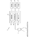
- the figure which shows the structure of an image inspection apparatus typically.
- inspection processing. 6 is a flowchart showing a flow of processing for setting an inspection region using a setting tool 103;
- the present invention can estimate both the foreground and background color distributions by simply specifying a part of the foreground, and use these color distributions as conditions. This realizes accurate area division.
- the area dividing method according to the present invention can be used as elemental technologies for various digital image processing, computer vision, and machine vision.
- a process for extracting an area to be inspected from an original image in an image inspection apparatus a process for detecting a face / human body / finger (gesture) area or contour from a still image or video, and a video from an in-vehicle camera Processing to detect white lines on roads, signs, and predetermined objects, processing to set an input target area when building a learning database for image processing, and foreground from the original image when performing background composition in image editing
- Various application examples such as a process of trimming only a part and a process of extracting only an organ or a part to be diagnosed from a medical image are conceivable.
- an example in which the region dividing method according to the present invention is implemented in an inspection region setting function (setting tool) in an image inspection apparatus will be described as an application example.
- FIG. 1 schematically shows the configuration of the image inspection apparatus.
- the image inspection apparatus 1 is a system that performs an appearance inspection of an inspection object 2 that is transported on a transport path.
- the image inspection apparatus 1 includes hardware such as an apparatus main body 10, an image sensor 11, a display device 12, a storage device 13, and an input device 14.
- the image sensor 11 is a device for taking a color or monochrome still image or moving image into the apparatus main body 10, and for example, a digital camera can be suitably used. However, when a special image (such as an X-ray image or a thermo image) other than a visible light image is used for inspection, a sensor that matches the image may be used.
- the display device 12 is a device for displaying an image captured by the image sensor 11, an inspection result, a GUI screen related to inspection processing and setting processing, and for example, a liquid crystal display can be used.
- the storage device 13 is a device that stores various setting information (inspection area definition information, inspection logic, etc.), inspection results, and the like that the image inspection apparatus 1 refers to in the inspection processing.
- various setting information inspection area definition information, inspection logic, etc.
- inspection results and the like that the image inspection apparatus 1 refers to in the inspection processing.
- an HDD, SSD, flash memory, network storage Etc. are available.
- the input device 14 is a device that is operated by a user to input an instruction to the device main body 10.
- a mouse, a keyboard, a touch panel, a dedicated console, or the like can be used.
- the apparatus main body 10 can be configured as a computer including a CPU (Central Processing Unit), a main storage (RAM), and an auxiliary storage (ROM, HDD, SSD, etc.) as hardware.
- An inspection processing unit 101, an inspection region extraction unit 102, and a setting tool 103 are provided.
- the inspection processing unit 101 and the inspection area extraction unit 102 are functions related to the inspection processing, and the setting tool 103 is a function that supports setting work by the user of setting information necessary for the inspection processing. These functions are realized by loading a computer program stored in the auxiliary storage device or the storage device 13 into the main storage device and executing it by the CPU. Note that FIG.
- the apparatus main body 10 may be configured by a computer such as a personal computer or a slate type terminal, or may be configured by a dedicated chip or an on-board computer.
- FIG. 2 is a flowchart showing a flow of the inspection process
- FIG. 3 is a diagram for explaining an inspection region extraction process in the inspection process.
- the flow of the inspection process will be described by taking as an example inspection (detection of scratches and color unevenness) of the panel surface of the casing component of the mobile phone.
- step S20 the inspection object 2 is photographed by the image sensor 11, and the image data is taken into the apparatus main body 10.
- the captured image (original image) is displayed on the display device 12 as necessary.
- the upper part of FIG. 3 shows an example of the original image.
- a case part 2 to be inspected is shown in the center of the original image, and a part of the case part adjacent to the conveyance path is shown on the left and right sides thereof.
- the inspection area extraction unit 102 reads necessary setting information from the storage device 13.
- the setting information includes at least inspection area definition information and inspection logic.
- the inspection area definition information is information that defines the position / shape of the inspection area to be extracted from the original image.
- the format of the inspection area definition information is arbitrary. For example, a bit mask in which the label is changed between the inside and outside of the inspection area, vector data in which the outline of the inspection area is expressed by a Bezier curve or a spline curve, or the like can be used.
- the inspection logic is information that defines the content of the inspection process, and includes, for example, the type of feature amount used for inspection, the determination method, the parameter used in feature amount extraction and determination processing, the threshold value, and the like.
- the inspection region extraction unit 102 extracts a portion to be an inspection region from the original image according to the inspection region definition information.
- the middle part of FIG. 3 shows a state in which the inspection area (indicated by cross hatching) 30 defined by the inspection area definition information is superimposed on the original image. It can be seen that the inspection region 30 just overlaps the panel surface of the casing component 2.
- the lower part of FIG. 3 shows a state in which an image of the portion of the inspection region 30 (inspection region image 31) is extracted from the original image.
- the inspection area image 31 the conveyance path and adjacent components that have been shown around the casing component 2 are deleted. Further, the hinge part 20 and the button part 21 that are excluded from the target parts for the surface inspection are also deleted.
- the inspection area image 31 obtained in this way is delivered to the inspection processing unit 101.
- step S23 the inspection processing unit 101 analyzes the inspection region image 31 according to the inspection logic and extracts a necessary feature amount.
- the color of each pixel of the inspection region image 31 and its average value are extracted as the feature amount for inspecting the surface for scratches and color unevenness.
- step S24 the inspection processing unit 101 determines the presence or absence of scratches or color unevenness according to the inspection logic. For example, when a pixel group in which the color difference with respect to the average value obtained in step S23 exceeds a threshold value, the pixel group can be determined as a flaw or color unevenness.
- step S25 the inspection processing unit 101 displays the inspection result on the display device 12 and records it in the storage device 13.
- the inspection process for one inspection object 2 is completed.
- the processing of steps S20 to S25 in FIG. 2 is repeated in synchronization with the timing at which the inspection object 2 is conveyed within the angle of view of the image sensor 11.
- the inspection area image 31 includes a background portion or an extra portion (in the example of FIG. 3, the hinge portion 20 or the button portion 21), the pixel may become noise and reduce the inspection accuracy. This is because if the inspection area image 31 is smaller than the range to be inspected, there is a risk of inspection leakage. Therefore, in the image inspection apparatus 1 according to the present embodiment, a setting tool 103 for easily creating inspection area definition information for cutting out an accurate inspection area image is prepared.
- FIG. 4 is a flowchart showing a flow of processing for setting an inspection region using the setting tool 103.
- the inspection area setting screen example in FIG. 5 is also referred to as appropriate.
- the setting screen shown in FIG. In this setting screen, an image window 50, an image capture button 51, a tool button 52, an area division button 53, a confirmation button 54, and a setting change button 55 are provided. Selection of a button, drawing of an image displayed in the image window 50 (designation of foreground), and the like can be performed by a predetermined operation using the input device 14 (for example, clicking or dragging a mouse, pressing a predetermined key, etc.). . Note that this setting screen is merely an example, and any UI may be used as long as the following input operation and image confirmation can be performed.
- the setting tool 103 captures a sample of the inspection object by the image sensor 11 (step S40).
- a sample a non-defective inspection object is used, and it is preferable to perform imaging in the same state (relative position between the image sensor 11 and the sample, illumination, etc.) as in the actual inspection process.
- the obtained sample image data is taken into the apparatus main body 10.
- the setting tool 103 may read sample image data from the auxiliary storage device or the storage device 13. .
- the sample image captured in step S40 is displayed in the image window 50 of the setting screen as shown in FIG. 5 (step S41).
- the object has a complicated shape, or the difference in color or brightness between the foreground (the part to be extracted as the inspection area) and the background (the other part) is not so large. In this case, it is difficult for the computer to automatically interpret and determine where to set the inspection area. Therefore, in this embodiment, the user teaches the computer a part of the area that should be the foreground in the sample image as an initial value.
- the foreground is designated by an operation of drawing a figure at an arbitrary position on the sample image (hereinafter, this figure is referred to as a foreground designation figure).
- the setting tool 103 prepares a line drawing tool, a curve drawing tool, a circle drawing tool, a rectangle drawing tool, a closed figure drawing tool, and an eraser tool as tools for drawing the foreground designation figure.
- the tool can be switched by selecting a corresponding icon in the tool button 52.
- a straight line drawing tool straight lines or continuous straight lines (polygonal lines) can be drawn on the sample image displayed in the image window 50 as shown in FIG.
- the thickness of the line can be changed arbitrarily.
- the straight line input operation may be performed using an operation used in CAD, draw software, or the like (for example, click of start point and end point, combination of start point click and drag, etc.), and thus description thereof is omitted here.
- a curve drawing tool a free curve, a Bezier curve, or a spline curve can be drawn on an image as shown in FIG.
- a circle drawing tool is used, a circle or an ellipse can be drawn as shown in FIG.
- the rectangle drawing tool When the rectangle drawing tool is used, a square or a rectangle can be drawn as shown in FIG.
- the closed figure drawing tool an arbitrary closed figure defined by a free curve can be drawn as shown in FIG.
- the area inside the circle, rectangle, or closed figure may be the foreground designation figure, or the outline of the figure as with the line drawing tool or curve drawing tool
- the portion may be a foreground designation figure.
- the eraser tool is a tool for erasing a drawn figure. These tools are merely examples, and any tool may be used as long as a part of the area on the image can be designated by a line, polygon, or other closed figure.
- the area division button 53 can be selected. Thereafter, when the user presses the region division button 53, the setting tool 103 acquires data of a pixel (referred to as a foreground designation pixel) of a portion where the foreground designation figure is superimposed from the sample image (step S43). . Then, the setting tool 103 estimates the color distribution of the representative colors of the foreground and the background based on the colors of the foreground designation pixels by the method described below.
- the setting tool 103 maps the value (color) of each pixel of the sample image into a predetermined color space (step S44).
- the color space the same color space as the color channel of the sample image (for example, RGB color space) may be used, or another color space such as L * a * b * or XYZ may be used.
- L * a * b * or XYZ may be used.
- a two-dimensional or one-dimensional color space may be used.
- FIG. 7A schematically shows an example of the mapping result (for the convenience of illustration, an example of a two-dimensional color space is shown).
- the x mark represents the mapped pixel. In an actual image, there are hundreds of thousands to millions of pixels, but in FIG.
- the setting tool 103 divides the pixel group (that is, the color distribution of the sample image) mapped in the color space into a plurality of clusters based on the color similarity (step S45).
- a clustering algorithm any algorithm such as GMM (Gaussian MixtureKModel) clustering, K-means method, mean-shift method, infinite mixed Dirichlet distribution may be used, but in this embodiment, GMM clustering is used. It is preferable. This is because GMM is used for likelihood calculation in the optimal solution search at the subsequent stage, and thus there is an advantage that the calculation result of GMM clustering can be used for the optimal solution search as it is.
- the number of clusters (number of divisions) may be determined dynamically, or may be set by the user.
- FIG. 7B schematically shows an example in which the cluster is divided into six clusters 71 to 76 as an example of the clustering result.
- the setting tool 103 evaluates the magnitude of the relationship with each of the six clusters 71 to 76 with the foreground designation pixel acquired in step S43 (step S46). Specifically, the setting tool 103 counts the foreground designation pixels included in each cluster, and calculates a score representing the degree of association with the foreground designation pixels based on the count result.
- the foreground designation pixel is indicated by a circle. It can be seen that the clusters 71, 72, and 73 include foreground designation pixels, and the remaining clusters 74, 75, and 76 do not include foreground designation pixels.
- the result of counting one foreground designated pixel (that is, the total number of foreground designated pixels in the cluster) is used as the score.
- the score of the cluster 73 is “5”
- the scores of the clusters 71 and 72 are “2”
- the scores of the clusters 74, 75, and 76 are “0”
- the cluster 73 has the largest relevance with the foreground designation pixel.
- the evaluation result that the clusters 74, 75, and 76 are the smallest is obtained.
- the setting tool 103 may count the foreground designated pixels by assigning a weight according to the position of the foreground designated pixels. For example, the weight of the pixel at the center of the foreground designating graphic drawn by the user may be larger than the weight of the pixel at the periphery. This is because the user is highly likely to draw a figure centering on a portion that is considered to be a typical foreground portion. If the weights of the peripheral pixels are reduced, there is an advantage that the influence on the score can be reduced even if the edge of the figure protrudes from the foreground and covers the background.
- the pixel weight can be changed for each figure. For example, it is conceivable to increase the weight for a graphic at the center, increase the weight for a graphic with a smaller area, or allow the user to specify a weight for each graphic.
- the weight control according to the position of the foreground designation pixel in the image is performed, but the weight control according to the position of the foreground designation pixel in the color space (in the cluster) can also be performed.
- the weight of the pixel at the center of the cluster may be larger than the weight of the pixel at the periphery of the cluster. This is because the more the foreground designation pixels are concentrated at the center of the cluster, the higher the probability that the cluster represents the foreground color.
- the setting tool 103 selects one or more clusters having a large relationship with the foreground designation pixel from the six clusters 71 to 76, and determines a GMM obtained by synthesizing them as a foreground color distribution (step S47). ).
- all clusters having a score of 1 or more that is, clusters including one or more foreground designation pixels
- a GMM composed of three clusters 71, 72, 73 is the foreground color distribution.
- the method of selecting a cluster in step S47 is not limited to the above example.
- the threshold value for determining whether or not the relevance (score) with the foreground designation pixel is large may be set to a value larger than 1, or the threshold value may be changed by the user. It is also preferable to dynamically change the threshold according to the total number of foreground designated pixels, the distribution of foreground designated pixels, and the like.
- the clusters are sorted in descending order of the relationship (score) with the foreground designation pixel, and a predetermined number of clusters are sorted in descending order of the relationship with the foreground designation pixel. You can also choose the color distribution.
- the predetermined number can be set to an arbitrary value of 1 or more, and may be changed by the user. It is also preferable to dynamically change the number of clusters to be selected as the foreground color distribution in accordance with the total number of foreground designation pixels, the number of cluster divisions, and the like.
- the setting tool 103 selects one or more clusters having a small relationship with the foreground designation pixel from the six clusters 71 to 76, and determines a GMM obtained by synthesizing them as a background color distribution (step S48). ). In the present embodiment, all clusters having a score smaller than 1 (that is, not including any foreground designation pixels) are selected. In the example of FIG. 7C, a GMM composed of three clusters 74, 75, and 76 is the background color distribution.
- the threshold value for determining whether or not the relevance (score) with the foreground designation pixel is small may be set to a value larger than 1, or the threshold value may be changed by the user. It is also preferable to dynamically change the threshold according to the total number of foreground designated pixels, the distribution of foreground designated pixels, and the like. Or, instead of deciding by comparing the score with the threshold, the clusters are sorted in ascending order of relevance (score) with the foreground designation pixel, and a predetermined number of clusters are sorted in the order of decreasing relevance to the foreground designation pixel. You can also choose the color distribution.
- the predetermined number can be set to an arbitrary value of 1 or more, and may be changed by the user. It is also preferable to dynamically change the number of clusters to be selected as the background color distribution in accordance with the total number of foreground designation pixels, the number of cluster divisions, and the like.
- steps S47 and S48 it is preferable to consider not only the relationship with the foreground designation pixels but also the distance between clusters (distance in the color space). For example, if it is known in advance that the color difference between the foreground and the background is clear, and there are many background cluster candidates, the color from the cluster selected as the foreground color distribution A cluster that is far away may be selected as a background cluster preferentially. Alternatively, in order to comprehensively sample the background color, the background cluster may be selected so that the distance between the clusters is as large as possible. The same applies to the foreground cluster.
- the setting tool 103 performs segmentation on the sample image using the foreground color distribution and the background color distribution estimated in steps S44 to S48 as initial conditions (step S49).
- Any algorithm can be used for region segmentation, but it is preferable to use a contour-based algorithm that searches for an optimal boundary between the foreground and the background.
- an algorithm such as graph cut or level set can be suitably used.
- foreground region candidate solutions candidate regions
- the foreground likelihood (foreground likelihood) of the color of each pixel can be calculated using the GMM which is the foreground color distribution obtained in step S47 as a probability density function.
- the background likelihood (background likelihood) of the color of each pixel can be calculated using the GMM that is the background color distribution obtained in step S48 as a probability density function.
- an expression for evaluating the total value of the foreground likelihood of each pixel inside the candidate region and the background likelihood of each pixel outside the candidate region is used as the data term of the objective function. Good.
- an equation for evaluating edge weights in the vicinity of 4 of each pixel can be used. Since the graph cut algorithm is a known method (see Non-Patent Document 1, etc.), detailed description is omitted here.
- the foreground candidate area may be set so as to include all foreground designated pixels designated by the user. This is because the search range can be narrowed by using the position information of the foreground designating pixels as an initial condition as described above, and the accuracy of the optimum solution search can be improved and the processing time can be shortened.
- the setting tool 103 displays the foreground area (or the boundary between the foreground area and the background area) extracted as a result of the area division in step S49 on the sample image (step S50). By viewing this display, the user can confirm whether or not the desired area has been extracted as the foreground. Thereafter, when the confirm button 54 is pressed by the user, the setting tool 103 determines the foreground area as the inspection area, generates inspection area definition information, and stores it in the storage device 13 (step S51).
- step S49 the processing may be performed again from image capture (step S40) or foreground designation (step S42).
- a setting change button 55 by pressing a setting change button 55, a setting change dialog can be displayed, and setting parameters relating to foreground designation and area division can be adjusted.
- setting parameters for example, the thickness of a line (brush) when drawing a foreground designating figure, the number of cluster divisions, the method for determining the color distribution of each of the foreground and background, the threshold value, and the like may be adjusted.
- the optimal solution for the foreground area is obtained using an area division algorithm such as graph cut or level set, the boundary between the foreground and the background can be determined with high accuracy.
- the search range is set so as to include the foreground designated pixels designated by the user, both improvement in search accuracy and reduction in processing time can be achieved.
- the above-described embodiments show specific examples of the present invention, and are not intended to limit the scope of the present invention to these specific examples.
- the color information of the image is used.
- luminance (density) information may be used instead of the color information.
- the region dividing method of the present invention is not limited to the appearance inspection apparatus, and can be generally used as elemental technologies for various digital image processing, computer vision, and machine vision.
- Image inspection device 2 Inspection object 10: Device body, 11: Image sensor, 12: Display device, 13: Storage device, 14: Input device 101: Inspection processing unit, 102: Inspection region extraction unit, 103: Setting Tool 20: Hinge part, 21: Button part 30: Inspection area, 31: Inspection area image 50: Image window, 51: Image capture button, 52: Tool button, 53: Area division button, 54: Confirm button, 55: Setting change button 71-76: Cluster
Landscapes
- Engineering & Computer Science (AREA)
- Physics & Mathematics (AREA)
- General Physics & Mathematics (AREA)
- Theoretical Computer Science (AREA)
- Computer Vision & Pattern Recognition (AREA)
- Multimedia (AREA)
- Image Analysis (AREA)
- Image Processing (AREA)
- Facsimile Image Signal Circuits (AREA)
- Color Image Communication Systems (AREA)
Abstract
Description
図1は、画像検査装置の構成を模式的に示している。この画像検査装置1は、搬送路上を搬送される検査対象物2の外観検査を行うシステムである。
図2及び図3を参照して、画像検査装置1の検査処理に関わる動作を説明する。図2は、検査処理の流れを示すフローチャートであり、図3は、検査処理における検査領域の抽出過程を説明するための図である。ここでは、説明の便宜のため、携帯電話の筐体部品のパネル面の検査(キズ、色ムラの検出)を例に挙げて検査処理の流れを説明する。
図4のフローチャートに沿って、設定ツール103の機能及び動作について説明する。図4は、設定ツール103を用いて検査領域を設定する処理の流れを示すフローチャートである。また、適宜、図5の検査領域設定画面例も参照する。
本実施形態では、サンプル画像上の任意の位置に図形を描画する操作により、前景の指定が行われる(以下、この図形を前景指定図形と呼ぶ)。設定ツール103は、前景指定図形を描画するためのツールとして、直線描画ツール、曲線描画ツール、円描画ツール、矩形描画ツール、閉図形描画ツール、消しゴムツールを用意している。ツールボタン52における該当するアイコンを選択することで、ツールの切換が可能である。
まず設定ツール103は、サンプル画像の各ピクセルの値(色)を所定の色空間にマッピングする(ステップS44)。色空間としては、サンプル画像のカラーチャネルと同じ色空間(例えばRGB色空間)でもよいし、L*a*b*やXYZのような他の色空間を用いることもできる。また計算を簡単にするために、2次元や1次元の色空間を用いてもよい。図7(a)は、マッピング結果の一例を模式的に示している(図示の便宜から2次元の色空間の例を示す)。×マークがマッピングされたピクセルを表している。実際の画像では数十万から数百万程度のピクセルが存在するが、図7(a)では簡略化して示している。
続いて、設定ツール103は、ステップS44~S48で推定された前景の色分布と背景の色分布を初期条件として用いて、サンプル画像に対し領域分割(セグメンテーション)を実行する(ステップS49)。領域分割についてはいかなるアルゴリズムを利用することもできるが、前景と背景の最適な境界を探索する輪郭ベースのアルゴリズムを用いることが好ましい。例えば、グラフカットやレベルセットなどのアルゴリズムを好適に利用できる。これらのアルゴリズムでは、前景領域の候補解(候補領域)について、候補領域の内側のピクセルの色の前景らしさ(前景尤度)と候補領域の外側のピクセルの色の背景らしさ(背景尤度)を評価することで、複数の候補領域のなかから前景領域の最適解を探索する。ここで、各ピクセルの色の前景らしさ(前景尤度)は、ステップS47で得られた前景の色分布であるGMMを確率密度関数として用いて、計算できる。また、各ピクセルの色の背景らしさ(背景尤度)は、ステップS48で得られた背景の色分布であるGMMを確率密度関数として用いて、計算できる。例えば、グラフカットアルゴリズムを用いる場合には、候補領域の内側の各ピクセルの前景尤度と候補領域の外側の各ピクセルの背景尤度の合計値を評価する式を目的関数のデータ項として用いればよい。その場合の平滑化項には、例えば、各ピクセルの4近傍のエッジ重みを評価する式などを用いることができる。グラフカットアルゴリズムは公知の手法であるため(非特許文献1など参照)、ここでは詳しい説明は割愛する。
以上述べた設定ツール103によれば、ユーザは前景の一部を指定するだけでよい(背景を指定する必要がない)ので、ユーザの操作が直感的かつ簡易になる。そして、ユーザにより指定された前景指定ピクセルの色に基づいて前景の色分布と背景の色分布を推定し、前景と背景の両方の色分布を条件として用いて領域分割を行うので、前景の条件のみを用いる方法に比べて、精度の高い領域分割を行うことができる。また、対象物(前景)の大きさ等の事前知識を与える必要がないので、汎用性に優れるという利点もある。特に本実施形態では、グラフカットやレベルセットなどの領域分割アルゴリズムを利用して前景領域の最適解を求めているので、前景と背景の境界を精度良く決定することが可能となる。しかも、ユーザにより指定された前景指定ピクセルを包含するように探索範囲を設定するので、探索精度の向上と処理時間の短縮を両立できる。
2:検査対象物
10:装置本体、11:画像センサ、12:表示装置、13:記憶装置、14:入力装置
101:検査処理部、102:検査領域抽出部、103:設定ツール
20:ヒンジ部分、21:ボタン部分
30:検査領域、31:検査領域画像
50:画像ウィンドウ、51:画像取込ボタン、52:ツールボタン、53:領域分割ボタン、54:確定ボタン、55:設定変更ボタン
71-76:クラスタ
Claims (11)
- 画像を前景と背景に分割する領域分割方法であって、
コンピュータが、前記画像のうち前景とすべき領域内の一部のピクセルを前景指定ピクセルとしてユーザに指定させる前景指定ステップと、
コンピュータが、ユーザにより指定された前記前景指定ピクセルの色に基づいて、前景の色分布と背景の色分布を推定する推定ステップと、
コンピュータが、推定された前記前景の色分布と前記背景の色分布を条件として用いて、前記画像を前景領域と背景領域に分割する領域分割ステップと、を含み、
前記推定ステップは、
前記画像の色分布を複数のクラスタに分けるステップと、
前記複数のクラスタのうち、ユーザにより指定された前記前景指定ピクセルとの関連性が大きい一以上のクラスタを前記前景の色分布として選び、前記前景指定ピクセルとの関連性が小さい一以上のクラスタを前記背景の色分布として選ぶステップと、を含む
ことを特徴とする領域分割方法。 - 前記領域分割ステップでは、前景領域の候補解である複数の候補領域について、前記前景の色分布に対する候補領域の内側の各ピクセルの色の前景らしさと前記背景の色分布に対する候補領域の外側の各ピクセルの色の背景らしさとを評価することにより、前記複数の候補領域のなかから前景領域の最適解が求められる
ことを特徴とする請求項1に記載の領域分割方法。 - 前記領域分割ステップでは、ユーザにより指定された前記前景指定ピクセルを包含するように前記複数の候補領域が設定される
ことを特徴とする請求項2に記載の領域分割方法。 - 前記推定ステップでは、前記複数のクラスタの各々について、クラスタに含まれる前記前景指定ピクセルをカウントした結果に基づいて前記前景指定ピクセルとの関連性の大きさを評価する
ことを特徴とする請求項1~3のうちいずれか1項に記載の領域分割方法。 - 前記推定ステップでは、クラスタに含まれる前記前景指定ピクセルをカウントするときに、前記前景指定ピクセルの位置に応じた重みを付けてカウントする
ことを特徴とする請求項4に記載の領域分割方法。 - 前記推定ステップでは、前記前景指定ピクセルとの関連性が閾値以上であるクラスタ、または、前記前景指定ピクセルとの関連性が大きいものから順に所定数のクラスタが、前記前景の色分布として選ばれる
ことを特徴とする請求項1~5のうちいずれか1項に記載の領域分割方法。 - 前記推定ステップでは、前記前景指定ピクセルを含まないクラスタ、前記前景指定ピクセルとの関連性が閾値より小さいクラスタ、または、前記前景指定ピクセルとの関連性が小さいものから順に所定数のクラスタが、前記背景の色分布として選ばれる
ことを特徴とする請求項1~6のうちいずれか1項に記載の領域分割方法。 - 前記前景ステップでは、表示装置に表示した前記画像の上に図形を描画する操作により、前記前景指定ピクセルの指定が行われる
ことを特徴とする請求項1~7のうちいずれか1項に記載の領域分割方法。 - 前記図形は、直線、曲線、円、楕円、多角形、または、閉図形である
ことを特徴とする請求項8に記載の領域分割方法。 - 請求項1~9のうちいずれか1項に記載の領域分割方法の各ステップをコンピュータに実行させる
ことを特徴とするプログラム。 - 検査対象物を撮影して得られた元画像の一部に検査領域を設定し、前記検査領域内の画像を解析することにより前記検査対象物の検査を行う検査装置であって、
請求項1~9のうちいずれか1項に記載の領域分割方法を用いて前記元画像を前景領域と背景領域に分割し、前記前景領域を前記検査領域として設定する
ことを特徴とする検査装置。
Priority Applications (4)
| Application Number | Priority Date | Filing Date | Title |
|---|---|---|---|
| US14/781,075 US9672628B2 (en) | 2013-03-29 | 2014-02-25 | Method for partitioning area, and inspection device |
| CN201480018765.6A CN105122306B (zh) | 2013-03-29 | 2014-02-25 | 区域分割方法以及检查装置 |
| EP14775567.2A EP2980755B1 (en) | 2013-03-29 | 2014-02-25 | Method for partitioning area, and inspection device |
| KR1020157026294A KR101719088B1 (ko) | 2013-03-29 | 2014-02-25 | 영역 분할 방법 및 검사 장치 |
Applications Claiming Priority (2)
| Application Number | Priority Date | Filing Date | Title |
|---|---|---|---|
| JP2013073545A JP6089886B2 (ja) | 2013-03-29 | 2013-03-29 | 領域分割方法および検査装置 |
| JP2013-073545 | 2013-03-29 |
Publications (1)
| Publication Number | Publication Date |
|---|---|
| WO2014156425A1 true WO2014156425A1 (ja) | 2014-10-02 |
Family
ID=51623422
Family Applications (1)
| Application Number | Title | Priority Date | Filing Date |
|---|---|---|---|
| PCT/JP2014/054462 Ceased WO2014156425A1 (ja) | 2013-03-29 | 2014-02-25 | 領域分割方法および検査装置 |
Country Status (7)
| Country | Link |
|---|---|
| US (1) | US9672628B2 (ja) |
| EP (1) | EP2980755B1 (ja) |
| JP (1) | JP6089886B2 (ja) |
| KR (1) | KR101719088B1 (ja) |
| CN (1) | CN105122306B (ja) |
| TW (1) | TWI526982B (ja) |
| WO (1) | WO2014156425A1 (ja) |
Families Citing this family (17)
| Publication number | Priority date | Publication date | Assignee | Title |
|---|---|---|---|---|
| KR101766740B1 (ko) * | 2015-03-19 | 2017-08-09 | 한국전자통신연구원 | 영역 기반 그래프 컷을 이용한 객체 분할 장치 및 방법 |
| JP6919982B2 (ja) * | 2017-05-09 | 2021-08-18 | 株式会社キーエンス | 画像検査装置 |
| CN107358614B (zh) * | 2017-06-14 | 2020-07-28 | 南京邮电大学 | 从k边缘特性x射线图像中分离图像信息的方法 |
| TWI658430B (zh) * | 2017-12-12 | 2019-05-01 | Wistron Corporation | 熱影像處理系統及方法 |
| KR102064367B1 (ko) * | 2018-05-04 | 2020-02-11 | 주식회사 셀바스에이아이 | 이미지 태깅 장치 및 이를 이용한 이미지 태깅 방법 |
| TWI674558B (zh) | 2018-06-12 | 2019-10-11 | 財團法人工業技術研究院 | 數值陣列資料影像處理裝置、數值陣列資料影像處理方法及色碼表產生方法 |
| JP7469330B2 (ja) * | 2019-04-23 | 2024-04-16 | ロレアル | 機械画像色の抽出および抽出された色を用いた機械画像構築 |
| JP7110163B2 (ja) * | 2019-09-13 | 2022-08-01 | 富士フイルム株式会社 | 画像処理装置、撮影装置、画像処理方法、及び画像処理プログラム |
| TWI726525B (zh) * | 2019-12-09 | 2021-05-01 | 新唐科技股份有限公司 | 影像二值化方法與電子裝置 |
| EP4111358A1 (en) * | 2020-02-28 | 2023-01-04 | trinamiX GmbH | Gesture recognition |
| JP2021149166A (ja) * | 2020-03-16 | 2021-09-27 | 富士フイルムビジネスイノベーション株式会社 | 画像処理装置及びプログラム |
| CN113434715B (zh) * | 2020-03-23 | 2024-06-21 | 瑞昱半导体股份有限公司 | 用于针对图像进行搜索的方法以及图像处理电路 |
| TWI751571B (zh) * | 2020-06-02 | 2022-01-01 | 仁寶電腦工業股份有限公司 | 環境氛圍調整系統及環境氛圍調整方法 |
| US12125207B2 (en) | 2020-09-11 | 2024-10-22 | Beijing Boe Optoelectronics Technology Co., Ltd. | Image segmentation method and apparatus and image three-dimensional reconstruction method and apparatus |
| US20220226720A1 (en) * | 2021-01-15 | 2022-07-21 | Christian Michael FROELICH | Method, System, and Device for Inspection of Scratch-Off Lottery Tickets |
| TWI797923B (zh) * | 2021-12-28 | 2023-04-01 | 國家中山科學研究院 | 遮罩係數空間之線上多物件分割與追蹤系統 |
| KR20250058420A (ko) * | 2023-10-23 | 2025-04-30 | 현대모비스 주식회사 | Avps 마커 기반 측위를 위한 avps 마커의 인식 방법 및 장치 |
Citations (6)
| Publication number | Priority date | Publication date | Assignee | Title |
|---|---|---|---|---|
| JP2007193553A (ja) | 2006-01-19 | 2007-08-02 | Fuji Xerox Co Ltd | 画像処理方法、画像処理装置および画像処理プログラム |
| JP2008245719A (ja) | 2007-03-29 | 2008-10-16 | Fujifilm Corp | 対象領域抽出方法および装置ならびにプログラム |
| JP2010028608A (ja) * | 2008-07-23 | 2010-02-04 | Sanyo Electric Co Ltd | 画像処理装置、撮像装置、再生装置及び画像処理方法 |
| JP2010039999A (ja) * | 2008-08-08 | 2010-02-18 | Toyota Motor Corp | 画像セグメンテーション方法、プログラムおよび装置 |
| JP2010079477A (ja) * | 2008-09-25 | 2010-04-08 | Rakuten Inc | 前景領域抽出プログラム、前景領域抽出装置、及び前景領域抽出方法 |
| JP2012200025A (ja) * | 2008-03-14 | 2012-10-18 | Omron Corp | 画像処理装置 |
Family Cites Families (5)
| Publication number | Priority date | Publication date | Assignee | Title |
|---|---|---|---|---|
| US5883971A (en) * | 1996-10-23 | 1999-03-16 | International Business Machines Corporation | System and method for determining if a fingerprint image contains an image portion representing a smudged fingerprint impression |
| JP2007052466A (ja) * | 2003-11-17 | 2007-03-01 | Nec Corp | 画像処理方法、画像処理システム、および画像処理プログラム |
| CN102685533B (zh) * | 2006-06-23 | 2015-03-18 | 图象公司 | 对2d电影进行转换用于立体3d显示的方法和系统 |
| JP5865078B2 (ja) * | 2011-12-28 | 2016-02-17 | キヤノン株式会社 | 画像処理装置および画像処理方法 |
| US8873887B2 (en) * | 2013-01-24 | 2014-10-28 | Google Inc. | Systems and methods for resizing an image |
-
2013
- 2013-03-29 JP JP2013073545A patent/JP6089886B2/ja active Active
-
2014
- 2014-02-21 TW TW103105765A patent/TWI526982B/zh active
- 2014-02-25 US US14/781,075 patent/US9672628B2/en active Active
- 2014-02-25 KR KR1020157026294A patent/KR101719088B1/ko active Active
- 2014-02-25 WO PCT/JP2014/054462 patent/WO2014156425A1/ja not_active Ceased
- 2014-02-25 CN CN201480018765.6A patent/CN105122306B/zh active Active
- 2014-02-25 EP EP14775567.2A patent/EP2980755B1/en active Active
Patent Citations (6)
| Publication number | Priority date | Publication date | Assignee | Title |
|---|---|---|---|---|
| JP2007193553A (ja) | 2006-01-19 | 2007-08-02 | Fuji Xerox Co Ltd | 画像処理方法、画像処理装置および画像処理プログラム |
| JP2008245719A (ja) | 2007-03-29 | 2008-10-16 | Fujifilm Corp | 対象領域抽出方法および装置ならびにプログラム |
| JP2012200025A (ja) * | 2008-03-14 | 2012-10-18 | Omron Corp | 画像処理装置 |
| JP2010028608A (ja) * | 2008-07-23 | 2010-02-04 | Sanyo Electric Co Ltd | 画像処理装置、撮像装置、再生装置及び画像処理方法 |
| JP2010039999A (ja) * | 2008-08-08 | 2010-02-18 | Toyota Motor Corp | 画像セグメンテーション方法、プログラムおよび装置 |
| JP2010079477A (ja) * | 2008-09-25 | 2010-04-08 | Rakuten Inc | 前景領域抽出プログラム、前景領域抽出装置、及び前景領域抽出方法 |
Non-Patent Citations (3)
| Title |
|---|
| See also references of EP2980755A4 |
| Y. BOYKOV; M. P. JOLLY: "Interactive Graph Cuts for Optimal Boundary & Region Segmentation of Objects in N-D images", ICCV2001, vol. 01, 2001, pages 105 |
| YIN LI, JIAN SUN ET AL.: "Lazy snapping", ACM TRANSACTIONS ON GRAPHICS (TOG, vol. 23, no. ISSUE, 1 January 2004 (2004-01-01), pages 303 - 308, XP009099127, DOI: 10.1145/1015706.1015719 * |
Also Published As
| Publication number | Publication date |
|---|---|
| JP6089886B2 (ja) | 2017-03-08 |
| US9672628B2 (en) | 2017-06-06 |
| TW201447811A (zh) | 2014-12-16 |
| CN105122306A (zh) | 2015-12-02 |
| CN105122306B (zh) | 2018-04-17 |
| EP2980755B1 (en) | 2019-05-01 |
| KR20150121164A (ko) | 2015-10-28 |
| KR101719088B1 (ko) | 2017-03-22 |
| US20160300358A1 (en) | 2016-10-13 |
| JP2014197358A (ja) | 2014-10-16 |
| EP2980755A1 (en) | 2016-02-03 |
| EP2980755A4 (en) | 2016-11-30 |
| TWI526982B (zh) | 2016-03-21 |
Similar Documents
| Publication | Publication Date | Title |
|---|---|---|
| JP6089886B2 (ja) | 領域分割方法および検査装置 | |
| CN109791693B (zh) | 用于提供可视化全切片图像分析的数字病理学系统及相关工作流程 | |
| US10540771B2 (en) | System and method for image segmentation | |
| US11734805B2 (en) | Utilizing context-aware sensors and multi-dimensional gesture inputs to efficiently generate enhanced digital images | |
| US11461880B2 (en) | Generating image masks from digital images utilizing color density estimation and deep learning models | |
| US11741683B2 (en) | Apparatus for processing labeled data to be used in learning of discriminator, method of controlling the apparatus, and non-transitory computer-readable recording medium | |
| CN104053984A (zh) | 图像检查方法和图像检查装置 | |
| WO2015074521A1 (en) | Devices and methods for positioning based on image detection | |
| US20150317537A1 (en) | Method and Apparatus for Image Scoring and Analysis | |
| WO2019181072A1 (ja) | 画像処理方法、コンピュータプログラムおよび記録媒体 | |
| CN108269260B (zh) | 动态影像去背方法、系统与计算机可读取存储装置 | |
| JP2016122367A5 (ja) | ||
| CN117635763B (zh) | 基于人像部件分析的自动换装方法、装置、设备及介质 | |
| CN114998263B (zh) | 用于百格测试的附着力分析方法及系统 | |
| CN117392698A (zh) | 手绘电路图的识别方法、装置、设备和存储介质 | |
| US20220254141A1 (en) | Image processing device, image processing method, and program | |
| JP2016045744A (ja) | 画像処理装置、画像処理方法、およびプログラム | |
| CN113807463B (zh) | 一种基于Faster-RCNN对BI图标题检测的方法 | |
| TWI791910B (zh) | 用於孔狀結構之檢測資訊呈現方法、檢測方法、及檢測設備 | |
| Audet et al. | Salient Object Detection in Images by Combining Objectness Clues in the RGBD Space | |
| CN121414886A (zh) | 用于矢量化光栅图像的高级图像跟踪 | |
| JP2016197362A (ja) | 範囲指定プログラム、範囲指定方法および範囲指定装置 |
Legal Events
| Date | Code | Title | Description |
|---|---|---|---|
| 121 | Ep: the epo has been informed by wipo that ep was designated in this application |
Ref document number: 14775567 Country of ref document: EP Kind code of ref document: A1 |
|
| WWE | Wipo information: entry into national phase |
Ref document number: 2014775567 Country of ref document: EP |
|
| ENP | Entry into the national phase |
Ref document number: 20157026294 Country of ref document: KR Kind code of ref document: A |
|
| NENP | Non-entry into the national phase |
Ref country code: DE |
|
| WWE | Wipo information: entry into national phase |
Ref document number: 14781075 Country of ref document: US |