WO2014156446A1 - 表面被覆窒化硼素焼結体工具 - Google Patents
表面被覆窒化硼素焼結体工具 Download PDFInfo
- Publication number
- WO2014156446A1 WO2014156446A1 PCT/JP2014/054684 JP2014054684W WO2014156446A1 WO 2014156446 A1 WO2014156446 A1 WO 2014156446A1 JP 2014054684 W JP2014054684 W JP 2014054684W WO 2014156446 A1 WO2014156446 A1 WO 2014156446A1
- Authority
- WO
- WIPO (PCT)
- Prior art keywords
- layer
- sintered body
- boron nitride
- nitride sintered
- less
- Prior art date
- Legal status (The legal status is an assumption and is not a legal conclusion. Google has not performed a legal analysis and makes no representation as to the accuracy of the status listed.)
- Ceased
Links
Images
Classifications
-
- C—CHEMISTRY; METALLURGY
- C23—COATING METALLIC MATERIAL; COATING MATERIAL WITH METALLIC MATERIAL; CHEMICAL SURFACE TREATMENT; DIFFUSION TREATMENT OF METALLIC MATERIAL; COATING BY VACUUM EVAPORATION, BY SPUTTERING, BY ION IMPLANTATION OR BY CHEMICAL VAPOUR DEPOSITION, IN GENERAL; INHIBITING CORROSION OF METALLIC MATERIAL OR INCRUSTATION IN GENERAL
- C23C—COATING METALLIC MATERIAL; COATING MATERIAL WITH METALLIC MATERIAL; SURFACE TREATMENT OF METALLIC MATERIAL BY DIFFUSION INTO THE SURFACE, BY CHEMICAL CONVERSION OR SUBSTITUTION; COATING BY VACUUM EVAPORATION, BY SPUTTERING, BY ION IMPLANTATION OR BY CHEMICAL VAPOUR DEPOSITION, IN GENERAL
- C23C14/00—Coating by vacuum evaporation, by sputtering or by ion implantation of the coating forming material
- C23C14/06—Coating by vacuum evaporation, by sputtering or by ion implantation of the coating forming material characterised by the coating material
- C23C14/0641—Nitrides
-
- B—PERFORMING OPERATIONS; TRANSPORTING
- B23—MACHINE TOOLS; METAL-WORKING NOT OTHERWISE PROVIDED FOR
- B23B—TURNING; BORING
- B23B27/00—Tools for turning or boring machines; Tools of a similar kind in general; Accessories therefor
- B23B27/14—Cutting tools of which the bits or tips or cutting inserts are of special material
- B23B27/148—Composition of the cutting inserts
-
- C—CHEMISTRY; METALLURGY
- C04—CEMENTS; CONCRETE; ARTIFICIAL STONE; CERAMICS; REFRACTORIES
- C04B—LIME, MAGNESIA; SLAG; CEMENTS; COMPOSITIONS THEREOF, e.g. MORTARS, CONCRETE OR LIKE BUILDING MATERIALS; ARTIFICIAL STONE; CERAMICS; REFRACTORIES; TREATMENT OF NATURAL STONE
- C04B41/00—After-treatment of mortars, concrete, artificial stone or ceramics; Treatment of natural stone
- C04B41/009—After-treatment of mortars, concrete, artificial stone or ceramics; Treatment of natural stone characterised by the material treated
-
- C—CHEMISTRY; METALLURGY
- C04—CEMENTS; CONCRETE; ARTIFICIAL STONE; CERAMICS; REFRACTORIES
- C04B—LIME, MAGNESIA; SLAG; CEMENTS; COMPOSITIONS THEREOF, e.g. MORTARS, CONCRETE OR LIKE BUILDING MATERIALS; ARTIFICIAL STONE; CERAMICS; REFRACTORIES; TREATMENT OF NATURAL STONE
- C04B41/00—After-treatment of mortars, concrete, artificial stone or ceramics; Treatment of natural stone
- C04B41/45—Coating or impregnating, e.g. injection in masonry, partial coating of green or fired ceramics, organic coating compositions for adhering together two concrete elements
- C04B41/52—Multiple coating or impregnating multiple coating or impregnating with the same composition or with compositions only differing in the concentration of the constituents, is classified as single coating or impregnation
-
- C—CHEMISTRY; METALLURGY
- C04—CEMENTS; CONCRETE; ARTIFICIAL STONE; CERAMICS; REFRACTORIES
- C04B—LIME, MAGNESIA; SLAG; CEMENTS; COMPOSITIONS THEREOF, e.g. MORTARS, CONCRETE OR LIKE BUILDING MATERIALS; ARTIFICIAL STONE; CERAMICS; REFRACTORIES; TREATMENT OF NATURAL STONE
- C04B41/00—After-treatment of mortars, concrete, artificial stone or ceramics; Treatment of natural stone
- C04B41/80—After-treatment of mortars, concrete, artificial stone or ceramics; Treatment of natural stone of only ceramics
- C04B41/81—Coating or impregnation
- C04B41/89—Coating or impregnation for obtaining at least two superposed coatings having different compositions
-
- C—CHEMISTRY; METALLURGY
- C23—COATING METALLIC MATERIAL; COATING MATERIAL WITH METALLIC MATERIAL; CHEMICAL SURFACE TREATMENT; DIFFUSION TREATMENT OF METALLIC MATERIAL; COATING BY VACUUM EVAPORATION, BY SPUTTERING, BY ION IMPLANTATION OR BY CHEMICAL VAPOUR DEPOSITION, IN GENERAL; INHIBITING CORROSION OF METALLIC MATERIAL OR INCRUSTATION IN GENERAL
- C23C—COATING METALLIC MATERIAL; COATING MATERIAL WITH METALLIC MATERIAL; SURFACE TREATMENT OF METALLIC MATERIAL BY DIFFUSION INTO THE SURFACE, BY CHEMICAL CONVERSION OR SUBSTITUTION; COATING BY VACUUM EVAPORATION, BY SPUTTERING, BY ION IMPLANTATION OR BY CHEMICAL VAPOUR DEPOSITION, IN GENERAL
- C23C14/00—Coating by vacuum evaporation, by sputtering or by ion implantation of the coating forming material
- C23C14/06—Coating by vacuum evaporation, by sputtering or by ion implantation of the coating forming material characterised by the coating material
- C23C14/0617—AIII BV compounds, where A is Al, Ga, In or Tl and B is N, P, As, Sb or Bi
-
- C—CHEMISTRY; METALLURGY
- C23—COATING METALLIC MATERIAL; COATING MATERIAL WITH METALLIC MATERIAL; CHEMICAL SURFACE TREATMENT; DIFFUSION TREATMENT OF METALLIC MATERIAL; COATING BY VACUUM EVAPORATION, BY SPUTTERING, BY ION IMPLANTATION OR BY CHEMICAL VAPOUR DEPOSITION, IN GENERAL; INHIBITING CORROSION OF METALLIC MATERIAL OR INCRUSTATION IN GENERAL
- C23C—COATING METALLIC MATERIAL; COATING MATERIAL WITH METALLIC MATERIAL; SURFACE TREATMENT OF METALLIC MATERIAL BY DIFFUSION INTO THE SURFACE, BY CHEMICAL CONVERSION OR SUBSTITUTION; COATING BY VACUUM EVAPORATION, BY SPUTTERING, BY ION IMPLANTATION OR BY CHEMICAL VAPOUR DEPOSITION, IN GENERAL
- C23C14/00—Coating by vacuum evaporation, by sputtering or by ion implantation of the coating forming material
- C23C14/06—Coating by vacuum evaporation, by sputtering or by ion implantation of the coating forming material characterised by the coating material
- C23C14/0635—Carbides
-
- C—CHEMISTRY; METALLURGY
- C23—COATING METALLIC MATERIAL; COATING MATERIAL WITH METALLIC MATERIAL; CHEMICAL SURFACE TREATMENT; DIFFUSION TREATMENT OF METALLIC MATERIAL; COATING BY VACUUM EVAPORATION, BY SPUTTERING, BY ION IMPLANTATION OR BY CHEMICAL VAPOUR DEPOSITION, IN GENERAL; INHIBITING CORROSION OF METALLIC MATERIAL OR INCRUSTATION IN GENERAL
- C23C—COATING METALLIC MATERIAL; COATING MATERIAL WITH METALLIC MATERIAL; SURFACE TREATMENT OF METALLIC MATERIAL BY DIFFUSION INTO THE SURFACE, BY CHEMICAL CONVERSION OR SUBSTITUTION; COATING BY VACUUM EVAPORATION, BY SPUTTERING, BY ION IMPLANTATION OR BY CHEMICAL VAPOUR DEPOSITION, IN GENERAL
- C23C14/00—Coating by vacuum evaporation, by sputtering or by ion implantation of the coating forming material
- C23C14/06—Coating by vacuum evaporation, by sputtering or by ion implantation of the coating forming material characterised by the coating material
- C23C14/0664—Carbonitrides
-
- C—CHEMISTRY; METALLURGY
- C23—COATING METALLIC MATERIAL; COATING MATERIAL WITH METALLIC MATERIAL; CHEMICAL SURFACE TREATMENT; DIFFUSION TREATMENT OF METALLIC MATERIAL; COATING BY VACUUM EVAPORATION, BY SPUTTERING, BY ION IMPLANTATION OR BY CHEMICAL VAPOUR DEPOSITION, IN GENERAL; INHIBITING CORROSION OF METALLIC MATERIAL OR INCRUSTATION IN GENERAL
- C23C—COATING METALLIC MATERIAL; COATING MATERIAL WITH METALLIC MATERIAL; SURFACE TREATMENT OF METALLIC MATERIAL BY DIFFUSION INTO THE SURFACE, BY CHEMICAL CONVERSION OR SUBSTITUTION; COATING BY VACUUM EVAPORATION, BY SPUTTERING, BY ION IMPLANTATION OR BY CHEMICAL VAPOUR DEPOSITION, IN GENERAL
- C23C28/00—Coating for obtaining at least two superposed coatings either by methods not provided for in a single one of groups C23C2/00 - C23C26/00 or by combinations of methods provided for in subclasses C23C and C25C or C25D
- C23C28/04—Coating for obtaining at least two superposed coatings either by methods not provided for in a single one of groups C23C2/00 - C23C26/00 or by combinations of methods provided for in subclasses C23C and C25C or C25D only coatings of inorganic non-metallic material
- C23C28/042—Coating for obtaining at least two superposed coatings either by methods not provided for in a single one of groups C23C2/00 - C23C26/00 or by combinations of methods provided for in subclasses C23C and C25C or C25D only coatings of inorganic non-metallic material including a refractory ceramic layer, e.g. refractory metal oxides, ZrO2, rare earth oxides
-
- C—CHEMISTRY; METALLURGY
- C23—COATING METALLIC MATERIAL; COATING MATERIAL WITH METALLIC MATERIAL; CHEMICAL SURFACE TREATMENT; DIFFUSION TREATMENT OF METALLIC MATERIAL; COATING BY VACUUM EVAPORATION, BY SPUTTERING, BY ION IMPLANTATION OR BY CHEMICAL VAPOUR DEPOSITION, IN GENERAL; INHIBITING CORROSION OF METALLIC MATERIAL OR INCRUSTATION IN GENERAL
- C23C—COATING METALLIC MATERIAL; COATING MATERIAL WITH METALLIC MATERIAL; SURFACE TREATMENT OF METALLIC MATERIAL BY DIFFUSION INTO THE SURFACE, BY CHEMICAL CONVERSION OR SUBSTITUTION; COATING BY VACUUM EVAPORATION, BY SPUTTERING, BY ION IMPLANTATION OR BY CHEMICAL VAPOUR DEPOSITION, IN GENERAL
- C23C28/00—Coating for obtaining at least two superposed coatings either by methods not provided for in a single one of groups C23C2/00 - C23C26/00 or by combinations of methods provided for in subclasses C23C and C25C or C25D
- C23C28/04—Coating for obtaining at least two superposed coatings either by methods not provided for in a single one of groups C23C2/00 - C23C26/00 or by combinations of methods provided for in subclasses C23C and C25C or C25D only coatings of inorganic non-metallic material
- C23C28/044—Coating for obtaining at least two superposed coatings either by methods not provided for in a single one of groups C23C2/00 - C23C26/00 or by combinations of methods provided for in subclasses C23C and C25C or C25D only coatings of inorganic non-metallic material coatings specially adapted for cutting tools or wear applications
-
- C—CHEMISTRY; METALLURGY
- C23—COATING METALLIC MATERIAL; COATING MATERIAL WITH METALLIC MATERIAL; CHEMICAL SURFACE TREATMENT; DIFFUSION TREATMENT OF METALLIC MATERIAL; COATING BY VACUUM EVAPORATION, BY SPUTTERING, BY ION IMPLANTATION OR BY CHEMICAL VAPOUR DEPOSITION, IN GENERAL; INHIBITING CORROSION OF METALLIC MATERIAL OR INCRUSTATION IN GENERAL
- C23C—COATING METALLIC MATERIAL; COATING MATERIAL WITH METALLIC MATERIAL; SURFACE TREATMENT OF METALLIC MATERIAL BY DIFFUSION INTO THE SURFACE, BY CHEMICAL CONVERSION OR SUBSTITUTION; COATING BY VACUUM EVAPORATION, BY SPUTTERING, BY ION IMPLANTATION OR BY CHEMICAL VAPOUR DEPOSITION, IN GENERAL
- C23C28/00—Coating for obtaining at least two superposed coatings either by methods not provided for in a single one of groups C23C2/00 - C23C26/00 or by combinations of methods provided for in subclasses C23C and C25C or C25D
- C23C28/40—Coatings including alternating layers following a pattern, a periodic or defined repetition
- C23C28/42—Coatings including alternating layers following a pattern, a periodic or defined repetition characterized by the composition of the alternating layers
-
- B—PERFORMING OPERATIONS; TRANSPORTING
- B23—MACHINE TOOLS; METAL-WORKING NOT OTHERWISE PROVIDED FOR
- B23B—TURNING; BORING
- B23B2226/00—Materials of tools or workpieces not comprising a metal
- B23B2226/12—Boron nitride
-
- B—PERFORMING OPERATIONS; TRANSPORTING
- B23—MACHINE TOOLS; METAL-WORKING NOT OTHERWISE PROVIDED FOR
- B23B—TURNING; BORING
- B23B2228/00—Properties of materials of tools or workpieces, materials of tools or workpieces applied in a specific manner
- B23B2228/10—Coatings
- B23B2228/105—Coatings with specified thickness
-
- B—PERFORMING OPERATIONS; TRANSPORTING
- B23—MACHINE TOOLS; METAL-WORKING NOT OTHERWISE PROVIDED FOR
- B23C—MILLING
- B23C2226/00—Materials of tools or workpieces not comprising a metal
- B23C2226/12—Boron nitride
-
- B—PERFORMING OPERATIONS; TRANSPORTING
- B23—MACHINE TOOLS; METAL-WORKING NOT OTHERWISE PROVIDED FOR
- B23C—MILLING
- B23C2228/00—Properties of materials of tools or workpieces, materials of tools or workpieces applied in a specific manner
- B23C2228/10—Coating
Definitions
- the present invention relates to a surface-coated boron nitride sintered body tool in which at least a cutting edge portion includes a cubic boron nitride sintered body and a coating film formed on the surface of the cubic boron nitride sintered body.
- a tool in which the surface of a cubic boron nitride sintered body is coated with a coating film such as a ceramic is used as a cutting tool for cutting hardened steel in order to exert excellent wear resistance.
- a coating film such as a ceramic
- Patent Document 1 WO 2010/150335 (Patent Document 1) and WO 2012/005275 (Patent Document 2) have specified the surface of the cubic boron nitride sintered body.
- the present invention has been made in view of such a situation, and the object of the present invention is to include a base material in which at least a cutting edge portion is made of a cubic boron nitride sintered body in processing of hardened steel etc. It is to improve the wear resistance of the tool.
- this inventor examined in detail the situation of wear of a tool which occurs when processing hardened steel. As a result, in addition to the usual crater wear and flank wear, it is clear that boundary wear occurs at the boundary of the front cutting edge which is one end of the wear portion, and this boundary wear has the greatest effect on the tool life. It turned out that it is giving.
- the present inventors obtained further finding that it is most effective to laminate a layer of a specific composition in a specific lamination mode in order to suppress this boundary wear.
- the present invention has been completed by further studies based on this finding.
- the surface-coated boron nitride sintered body tool includes at least a cutting edge portion of a cubic boron nitride sintered body and a covering layer formed on the surface of the cubic boron nitride sintered body.
- the cubic boron nitride sintered body contains 30% by volume or more and 80% by volume or less of cubic boron nitride, and nitrides, carbides, and nitrides of the group 4 element, the group 5 element and the group 6 element of the periodic table of elements.
- a bonding phase containing at least one compound selected from the group consisting of oxides, oxides and solid solutions thereof, an aluminum compound and an unavoidable impurity.
- the covering layer includes an A layer and a B layer.
- the A layer contains one or more elements of MLa za1 (where M represents a group 4 element, a group 5 element and a group 6 element of the periodic table of elements, Al and Si, and La represents one of B, C, N and O). (See above), and za1 is 0.85 or more and 1.0 or less.
- the layer B is formed by alternately laminating one or more layers of two or more kinds of compound layers different in composition. The thickness of each of the compound layers is 0.5 nm or more and less than 30 nm.
- B1 compound layer is one compound layer, (Ti 1-xb1-yb1 Si xb1 M1 yb1) (C 1-zb1 N zb1) (M1 is a Group 4 element of the periodic table of elements other than Ti, fifth Xb1 represents 0.01 or more and 0.25 or less, yb1 is 0 or more and 0.7 or less, and zb1 is 0.4 or more and 1 or less. It consists of.
- the B2 compound layer which is one kind of compound layer and is different from the B1 compound layer is (Al 1-xb 2 M 2 xb 2) (C 1-zb 2 N zb 2) (M 2 is a fourth element in the periodic table of elements, 5 And xb2 is 0.2 or more and 0.77 or less, and zb2 is 0.4 or more and 1 or less.
- the thickness of the A layer is 0.2 ⁇ m or more and 10 ⁇ m or less.
- the thickness of the B layer is 0.05 ⁇ m or more and 5 ⁇ m or less.
- the total thickness of the covering layer is 0.25 ⁇ m or more and 15 ⁇ m or less.
- a tool including a base material in which at least a cutting edge portion is formed of a cubic boron nitride sintered body in the processing of hardened steel and the like.
- At least the cutting edge portion of the surface-coated boron nitride sintered body tool according to the present invention is a cubic boron nitride sintered body (hereinafter referred to as "cBN sintered body”.
- CBN cubic boron nitride sintered body
- “CBN” is an abbreviation of "cubic Boron Nitride”.
- the covering layer formed on the surface of the cBN sintered body is an abbreviation of "cubic Boron Nitride”.
- the surface-coated boron nitride sintered body tool having such a basic configuration can be used particularly effectively in machining (for example, cutting) of a sintered alloy or hard-to-cut cast iron or in processing hardened steel, and further, It can be used suitably also in various processings of general metals other than.
- the cBN sintered body constitutes the base material of the surface-coated boron nitride sintered body tool of the cutting edge portion of the surface-coated boron nitride sintered body tool, and 30% by volume or more and 80% by volume or less of cubic boron nitride (hereinafter referred to as “cBN Further includes the bonding phase.
- the binder phase is selected from the group consisting of nitrides, carbides, borides, oxides and solid solutions thereof of Group 4 element, Group 5 element and Group 6 element of the periodic table of elements.
- the cBN comprises at least one compound, an aluminum compound and an unavoidable impurity, and the cBNs are bonded to each other.
- the cBN sintered body contains 30% by volume or more of cBN, the decrease in the wear resistance of the base material of the surface-coated boron nitride sintered body tool can be prevented.
- the cBN sintered body contains 80% by volume or less of cBN, cBN can be dispersed in the cBN sintered body, so that the bonding strength between cBNs in the bonding phase can be secured.
- the cBN content volume ratio is determined according to the following method. The cBN sintered body is mirror-polished, and a backscattered electron image of the cBN sintered body structure in an arbitrary region is photographed at 2000 ⁇ with an electron microscope.
- cBN particles particles composed of cBN
- the binder phase is gray regions or white regions.
- the cBN sintered body region and the binder phase region are binarized by image processing to determine the occupied area of the cBN particles.
- the volume fraction of cBN can be determined.
- the cBN sintered body contains 50% by volume or more and 65% by volume or less of cBN. If the cBN sintered body contains 50% by volume or more of cBN, it is possible to provide a base material of a surface-coated boron nitride sintered body tool excellent in the balance between wear resistance and fracture resistance. In addition, when the cBN sintered body contains 65% by volume or less of cBN, the bonding strength between cBN in the binder phase can be enhanced.
- the cBN particles are projected to the coating layer side more than the binder phase.
- the adhesiveness of cBN sintered compact and a coating layer can be improved.
- the step between the cBN particles and the binder phase is 0.05 ⁇ m or more and 1.0 ⁇ m or less. If this level
- step difference is 0.1 micrometer or more, an anchor effect can be acquired effectively. Moreover, if this level
- the level difference is measured according to the same method as the method of measuring the overall thickness of the covering layer described later, and the like.
- the volume content of cBN in the cBN sintered body is such that it increases from the interface between the cBN sintered body and the coating layer toward the inside of the cBN sintered body.
- the volume content of the binder phase is higher than the volume content of cBN, so the adhesion between the cBN sintered body and the coating layer can be enhanced.
- the volume fraction of cBN is higher than the volume fraction of binder phase inside the cBN sintered body, the fracture resistance of the cBN sintered body can be improved.
- the volume content of cBN is 40% by volume on the interface side with the coating layer (area separated from 0 ⁇ m to 20 ⁇ m from the interface between the cBN sintered body and the coating layer toward the inside of the cBN sintered body) And 60% by volume in the vicinity of the center in the thickness direction of the cBN sintered body (a region separated from the interface between the cBN sintered body and the coating layer toward the interior of the cBN sintered body by more than 20 ⁇ m and not more than 100 ⁇ m).
- the particle diameter of the cBN particles contained in the cBN sintered body is such that the particle diameter increases from the interface between the cBN sintered body and the coating layer toward the inside of the cBN sintered body.
- the particle diameter of the cBN particles is small, so that the adhesion between the cBN sintered body and the coating layer can be enhanced.
- the particle size of the cBN particles is large inside the cBN sintered body, the toughness can be enhanced.
- the particle diameter of cBN particles is 0.1 ⁇ m or more and 1 ⁇ m or less in a region away from 0 ⁇ m to 20 ⁇ m from the interface between the cBN sintered body and the coating layer toward the inside of the cBN sintered body It is 2 micrometers or more and 10 micrometers or less in the area
- the particle size of cBN particles is determined according to the following method. The diameter of the circle circumscribed to the cBN particles is measured in the backscattered electron image of the cBN sintered body structure obtained when determining the cBN content volume ratio, and the measured diameter is taken as the particle diameter of the cBN particles.
- the cBN sintered body may be provided in the cutting edge portion of the surface-coated boron nitride sintered body tool. Therefore, the base of the surface-coated boron nitride sintered body tool includes the cutting edge portion made of the cBN sintered body and the base body made of a material different from the cBN sintered body (for example, cemented carbide). It is also good.
- the cutting edge portion made of the cBN sintered body is preferably adhered to the base body through the brazing material or the like, and the material of the brazing material may be selected in consideration of the bonding strength or the melting point. it can.
- the cBN sintered body may constitute the entire base material of the surface-coated boron nitride sintered body tool.
- the covering layer includes an A layer and a B layer.
- the covering layer of the present invention may contain other layers in addition to the layer A and the layer B as long as the layer A and the layer B are included. Examples of such other layers include, but are not limited to, for example, the C layer provided between the A layer and the B layer or the D layer which is the lowermost layer as described later. .
- the thickness of the covering layer is 0.25 ⁇ m or more and 15 ⁇ m or less. If the thickness of the coating layer is 0.25 ⁇ m or more, it is possible to prevent the decrease in the wear resistance of the surface-coated boron nitride sintered body tool due to the thin thickness of the coating layer. If the thickness of the coating layer is 15 ⁇ m or less, the chipping resistance of the coating layer at the initial stage of cutting can be enhanced. Preferably, the thickness of the coating layer is 1.5 ⁇ m or more and 4.5 ⁇ m or less.
- the total thickness of the coating layer and the thickness and number of layers of each layer described later both cut the surface-coated boron nitride sintered body tool, and the cross section thereof is taken by SEM (scanning electron microscope) or TEM It is obtained by observation using a (transmission electron microscope).
- the composition of each layer as described below constituting the coating layer is measured using an SEM or TEM attached EDX analyzer (energy dispersive X-ray analyzer).
- the coating layer may be provided only on the cutting edge portion of the surface-coated boron nitride sintered body tool, but the entire surface of the base of the surface-coated boron nitride sintered body tool may be coated or cut It may not be provided in a part of a portion different from the blade portion. In addition, in a portion different from the cutting edge portion, the laminated configuration of a part of the covering layer may be partially different.
- the A layer contains one or more elements of MLa za1 (where M represents a group 4 element, a group 5 element and a group 6 element of the periodic table of elements, Al and Si, and La represents one of B, C, N and O). (See above), and za1 is 0.85 or more and 1.0 or less. Thereby, the A layer wears smoothly. In other words, the layer A wears without peeling, cracking or chipping. Therefore, crater wear resistance, flank wear resistance, etc. of the surface-coated boron nitride sintered body tool can be enhanced.
- a layer (Ti 1-xa Ma xa ) (C 1-za2 N za2) (Ma fourth group elements of the periodic table of elements other than Ti, group 5 element and a group 6 element, Al And one or more kinds of Si, xa is 0 or more and 0.7 or less, and za2 is 0 or more and 1 or less).
- the composition xa of Ma is 0 or more and 0.3 or less. This can further prevent peeling, cracking, chipping and the like of the layer A at the time of wear.
- xa When the layer A is composed of (Ti 1-xa (1) -xa (2) Ma (1) xa (1) Ma (2) xa (2 ) (C 1-za 2 N za 2) , xa
- the sum of (1) and xa (2) is preferably 0 or more and 0.7 or less, and more preferably 0 or more and 0.3 or less. This is also true for the B, C and D layers shown below.
- the composition of N changes in a step-like or inclined manner from the cBN sintered body side toward the surface side of the A layer.
- the composition of N is large on the cBN sintered body side of the A layer, chipping resistance and peeling resistance can be enhanced.
- the composition of N is small on the surface side of the layer A, it is possible to further prevent the peeling, cracking, chipping and the like of the layer A at the time of wear.
- composition of N changes stepwise from the cBN sintered body side to the surface side of the A layer
- composition of N is discontinuous from the cBN sintered body side to the surface side of the A layer It means decreasing or increasing, for example, a configuration obtained by laminating two or more layers having different compositions of N from one another.
- composition of N changes in a sloping shape from the cBN sintered body side to the surface side of the A layer means that the composition of N continuously decreases from the cBN sintered body side to the surface side of the A layer or For example, it is a configuration obtained by continuously changing and forming the flow ratio of the N source gas and the C source gas.
- the A layer has a region of a larger C composition on the surface side of the A layer than the cBN sintered body side.
- chipping resistance and peeling resistance can be enhanced on the cBN sintered body side of layer A, and on the surface side of layer A, peeling, cracking, chipping, etc. of layer A at the time of wear can be further prevented.
- the cBN sintered body side of the A layer means a region separated by 0 ⁇ m or more and 0.1 ⁇ m or less from the surface of the A layer located closest to the cBN sintered body toward the inside of the A layer.
- the surface side of A layer means the part different from the cBN sintered compact side of A layer.
- the thickness of the A layer is 0.2 ⁇ m or more and 10 ⁇ m or less. If the thickness of the A layer is 0.2 ⁇ m or more, it is possible to provide a surface-coated boron nitride sintered body tool excellent in crater wear resistance, flank wear resistance, and the like. On the other hand, if the thickness of the layer A exceeds 10 ⁇ m, it may be difficult to further improve the crater wear resistance or flank wear resistance of the surface-coated boron nitride sintered body tool. Preferably, the thickness of the A layer is 1 ⁇ m or more and 3 ⁇ m or less.
- the A layer is provided on the surface side of the surface-coated boron nitride sintered body tool than the B layer.
- the B layer can prevent the propagation of the generated crack to the base material side.
- the layer B is formed by alternately laminating one or more layers of two or more kinds of compound layers different in composition.
- the layer B is exemplified by one or more layers of alternately stacked B1 compound layers and B2 compound layers
- the B layer of the present invention includes the B1 compound layers and the B2 compound layers. As long as the layer is other than the B1 compound layer and the B2 compound layer, other layers may be included.
- the thickness of the B layer is 0.05 ⁇ m or more and 5 ⁇ m or less.
- the average value of the Si composition in the entire B layer is 0.005 or more and 0.1 or less.
- the average value of the Si composition in the entire B layer is more preferably 0.01 or more and 0.07 or less, and still more preferably 0.02 or more and 0.05 or less.
- B1 compound layer (Ti 1-xb1-yb1 Si xb1 M1 yb1) (C 1-zb1 N zb1) (M1 is a Group 4 element of the periodic table of elements other than Ti, group 5 element and a group 6 element And xb1 is 0.01 or more and 0.25 or less, yb1 is 0 or more and 0.7 or less, and zb1 is 0.4 or more and 1 or less).
- the thickness of the B1 compound layer is 0.5 nm or more and less than 30 nm.
- the B2 compound layer (Al 1 -x b 2 M 2 x b 2) (C 1-z b 2 N z b 2) (M 2 is at least one element of Group 4 element, Group 5 element and Group 6 element of the periodic table of elements and Si.
- Xb2 is 0.2 or more and 0.77 or less, and zb2 is 0.4 or more and 1 or less.
- M2 preferably represents at least one of Ti and Cr.
- the composition xb2 of M2 is preferably 0.25 or more and 0.5 or less, and more preferably 0.25 or more and 0.4 or less.
- the thickness of the B2 compound layer is 0.5 nm or more and less than 30 nm.
- the lowermost layer of the B layer may be a B1 compound layer or a B2 compound layer. Further, the uppermost layer of the B layer may be a B1 compound layer or a B2 compound layer.
- t2 / t1 which is the ratio of the average thickness t1 of the B1 compound layer to the average thickness t2 of the B2 compound layer, satisfies 0.5 ⁇ t2 / t1 ⁇ 10.0.
- the boundary wear resistance etc. of the surface-coated boron nitride sintered body tool can be further improved.
- the average thickness t1 of the B1 compound layer is determined using the following formula.
- the average thickness t1 of the B1 compound layer can be determined using the following formula. The same applies to the average thickness t2 of the B2 compound layer.
- Average thickness t1 of B1 compound layer (thickness of B layer formed by laminating only B1 compound layer) / (number of laminated B1 compound layers).
- t2 / t1 satisfies 1 ⁇ t2 / t1 ⁇ 5.0.
- the boundary wear resistance etc. of the surface-coated boron nitride sintered body tool can be further improved.
- t2 / t1 satisfies 1.1 ⁇ t2 / t1 ⁇ 4.5.
- t2 / t1 satisfies 1 ⁇ t2 / t1 ⁇ 5.0 on the cBN sintered body side and moves toward the layer A side. It becomes smaller, and 0.5 ⁇ t2 / t1 ⁇ 2 is satisfied on the A layer side. Thereby, generation of cracks can be prevented on the side of layer A of layer B, and propagation of cracks to the side of cBN sintered body can be prevented on the side of cBN sintered body of layer B.
- the layer A side of the layer B means a region separated from the surface of the layer B located closest to the layer A toward the interior of the layer B by 0 ⁇ m or more and a half or less of the thickness of the layer B, and It means the narrower one of the regions separated by 0 ⁇ m or more and 0.1 ⁇ m or less from the surface of the B layer located closest to the A layer toward the inside of the B layer.
- the cBN sintered body side of the B layer is a region separated from the surface of the B layer located closest to the cBN sintered body by 0 ⁇ m or more to 1/2 of the thickness of the B layer toward the inside of the B layer, Further, it means the narrower one of the regions separated by 0 ⁇ m or more and 0.1 ⁇ m or less from the surface of the B layer located closest to the cBN sintered body toward the inside of the B layer.
- the covering layer further includes a C layer provided between the A layer and the B layer, and the C layer is a McLc zc (Mc is a Group 4 element, a Group 5 element and the Periodic Table of the Elements)
- Lc represents one or more of a group 6 element, Al and Si
- Lc represents one or more of B, C, N and O
- zc is 0 or more and 0.85 or less.
- the thickness of the C layer is 0.005 ⁇ m or more and 0.5 ⁇ m or less.
- the thickness of the C layer is 0.005 ⁇ m or more, the effect obtained by providing the C layer can be sufficiently obtained. If the thickness of the C layer is 0.5 ⁇ m or less, the provision of the C layer can prevent the thickness of the covering layer from becoming too large. More preferably, the thickness of the C layer is 0.01 ⁇ m or more and 0.2 ⁇ m or less.
- the composition zc of Lc is greater than 0 and less than 0.7. If the composition zc of Lc is larger than 0, the heat resistance and the chemical abrasion resistance of the C layer can be enhanced, and thus the C layer effectively stops the propagation of the crack generated in the A layer to the substrate side. be able to. More preferably, the composition zc of Lc is 0.2 or more and 0.5 or less.
- the C layer contains at least one or more of the elements constituting the A layer and the B layer. If the C layer contains at least one or more of the elements constituting the A layer, the adhesion between the A layer and the C layer can be enhanced. If the C layer contains at least one or more of the elements constituting the B layer, the adhesion between the B layer and the C layer can be enhanced. More preferably, the C layer contains at least one or more of the elements constituting the portion located on the C layer side of each of the A layer and the B layer.
- the covering layer further includes a D layer provided between the substrate and the B layer, and the D layer is MdLd zd (where Md is a Group 4 element, a Group 5 element and the periodic table of the elements).
- Ld represents one or more of a group 6 element, Al and Si
- Ld represents one or more of B, C, N and O
- zd is 0.85 or more and 1.0 or less.
- Such a D layer is excellent in adhesion to the cBN sintered body. Therefore, if the covering layer further includes the D layer, the adhesion between the cBN sintered body and the covering layer can be enhanced. More preferably, Ld is N.
- D layer is (Al 1-xd Md2 xd) Ld zd
- Md2 is a Group 4 element of the Periodic Table of the Elements, represents one or more group 5 element and a group 6 element and Si, xd Is not less than 0.25 and not more than 0.45. If the D layer contains Al, the adhesion between the cBN sintered body and the coating layer can be further enhanced. More preferably, Md2 is at least one or more of Ti, Cr and V.
- the thickness of the D layer is 0.05 ⁇ m or more and 1 ⁇ m or less. If the thickness of the D layer is 0.05 ⁇ m or more, the effect obtained by providing the D layer can be sufficiently obtained. If the thickness of the D layer is 1 ⁇ m or less, the provision of the D layer can prevent the thickness of the covering layer from becoming too large. More preferably, the thickness of the D layer is 0.1 ⁇ m or more and 0.5 ⁇ m or less.
- ⁇ Method of manufacturing surface-coated boron nitride sintered body tool for example, a step of preparing a substrate having at least a cBN sintered body in a cutting edge portion, and a coating layer at least on the surface of the cBN sintered body And a forming step.
- the step of preparing the substrate preferably includes the step of forming the cBN sintered body, and the step of forming the cBN sintered body is sintering the mixture of the cBN particles and the raw material powder of the binder phase under high temperature and high pressure It is preferable to include the step of More preferably, the method of preparing the substrate further includes the step of bonding the cBN sintered body to a substrate body having a predetermined shape.
- the step of forming the covering layer preferably includes the step of forming the covering layer by an arc ion plating method (an ion plating method in which a solid material is evaporated using a vacuum arc discharge) or a sputtering method.
- the coating layer can be formed using a metal evaporation source containing a metal species that will constitute the coating layer and a reaction gas such as CH 4 , N 2 or O 2 .
- a reaction gas such as CH 4 , N 2 or O 2 .
- Known conditions can be adopted as the conditions for forming the covering layer.
- the coating layer is formed using a metal evaporation source containing a metal species that will constitute the coating layer, a reaction gas such as CH 4 , N 2 or O 2 , and a sputtering gas such as Ar, Kr or Xe. Can be formed.
- a metal evaporation source containing a metal species that will constitute the coating layer
- a reaction gas such as CH 4 , N 2 or O 2
- a sputtering gas such as Ar, Kr or Xe.
- Known conditions can be adopted as the conditions for forming the covering layer.
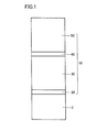
- FIG. 1 is a cross-sectional view showing an example of the configuration of a surface-coated boron nitride sintered body tool in the example.
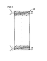
- FIG. 2 is sectional drawing which shows an example of a structure of the principal part of the surface-coated boron nitride sintered compact tool in an Example.
- the resulting mixture was heat treated under vacuum at 1000 ° C. for 30 minutes.
- the compound obtained by the heat treatment was uniformly pulverized by ball milling using a cemented carbide ball medium having a diameter of 6 mm. Thereby, the raw material powder of the binding phase was obtained.
- a boron nitride ball media having a diameter of 3 mm is prepared by blending cBN particles having an average particle diameter of 1.5 ⁇ m and a raw material powder of a binder phase so that the cBN content in the cBN sintered body is 30% by volume.
- the mixture was uniformly mixed by a ball mill mixing method using The obtained mixed powder was laminated on a cemented carbide support plate and then filled in a capsule made of Mo. After that, it was sintered at a temperature of 1300 ° C. for 30 minutes at a pressure of 5.5 GPa using an ultrahigh pressure apparatus. Thus, a cBN sintered body A was obtained.
- a base body made of cemented carbide material (equivalent to K10) which was DNGA 150408 of ISO standard was prepared.
- the cBN sintered body A shape: apex angle is 55 ° at the cutting edge (corner portion) of the prepared base body, and the thickness is 2 mm with an isosceles triangle having 2 mm on both sides sandwiching the apex angle. Of triangular prisms).
- a mouthpiece made of Ti-Zr-Cu was used for bonding.
- the outer peripheral surface, the upper surface, and the lower surface of the joined body were ground to form a negative land shape (negative land width is 150 ⁇ m, negative land angle is 25 °) on the cutting edge.
- the base material 3 in which the cutting edge portion is made of the cBN sintered body A was obtained.
- the obtained base material 3 was put into a film forming apparatus, vacuuming was performed, and after heating to 500 ° C., etching was performed using Ar ions. After that, Ar gas was exhausted from the inside of the film forming apparatus.
- the D layer 20 was formed on the substrate 3 in the film forming apparatus. Specifically, a D layer having a thickness of 0.5 ⁇ m was formed by vapor deposition under the conditions described below.
- Target 70 atomic percent of Al, 30 atomic percent of Cr Introduction gas: N 2 Deposition pressure: 4 Pa Arc discharge current: 120A Substrate bias voltage: -50V Table rotation speed: 5 rpm.
- the B layer 30 was formed on the D layer 20 in the film forming apparatus. Specifically, a B layer 30 having a total thickness of 0.03 ⁇ m was formed by vapor deposition under the conditions shown below. At this time, the arc current of the targets B1 and B2 and the rotation of the rotary table on which the base material is set so that the thickness of the B1 compound layer 31 is 7 nm and the thickness of the B2 compound layer 32 is 10 nm. Adjusted with speed.
- Target B1 75 atomic percent Ti, 15 atomic percent Si, 10 atomic percent Cr
- Target B2 60 atomic percent Al, 10 atomic percent Cr, 30 atomic percent Ti
- Introductory gas N 2 Deposition pressure: 1 Pa
- the C layer 40 was formed on the B layer 30 in the film forming apparatus. Specifically, a C layer 40 having a thickness of 0.1 ⁇ m was formed by vapor deposition under the conditions shown below.
- Target 50 atomic% of Ti, 50 atomic% of Al Introduction gas: N 2 Deposition pressure: 0.1 Pa Arc discharge current: 150A
- Substrate bias voltage -100V Table rotation speed: 5 rpm.
- the A layer 50 was formed on the C layer 40 in the film forming apparatus. Specifically, an A layer having a thickness of 2 ⁇ m was formed by vapor deposition under the conditions shown below.
- Target 50 atomic% of Ti, 50 atomic% of Al Introduction gas: N 2 Deposition pressure: 4 Pa
- the covering layer 10 in which the D layer 20, the B layer 30, the C layer 40, and the A layer 50 are sequentially laminated is formed on the base material 3, and thus, the sample 1 is manufactured. .
- the samples 2 to 6 are manufactured according to the method of manufacturing the sample 1 except that the total thickness of the B layer is changed by changing the number of layers of the B1 compound layer and the B2 compound layer to the values shown in Table 2. did.
- the number of layers in Table 2 indicates the total of the number of layers of the B1 compound layer and the number of layers of the B2 compound layer.
- cBN sintering is performed according to the method for forming cBN sintered body A except that the cBN particles and the raw material powder of the binder phase are blended so that the cBN content in the cBN sintered body becomes the numerical value shown in Table 3. I got a body D.
- the obtained cBN sintered body D was used to form a base of sample 7 in accordance with the method of manufacturing a base of sample 1 above.
- the C layer was formed according to the method of forming the C layer of the above-mentioned sample 1 except that the film forming pressure was changed as follows. That is, the film formation pressure was set to 3 Pa by introducing N 2 at the start of the formation of the C layer, and then gradually lowered to 0.1 Pa and then gradually raised to 3 Pa again.
- an A layer was formed according to the method for forming the A layer of the above-mentioned sample 1 except that the film forming pressure and the introduced gas were changed as follows. That is, only N 2 was introduced to set the deposition pressure to 3 Pa from the start of the formation of the layer A until the thickness of the layer A becomes 0.9 ⁇ m. After that, N 2 was gradually decreased while CH 4 was gradually increased to further form an A layer of 0.3 ⁇ m. At this time, N 2 was gradually decreased while CH 4 was gradually increased until the composition became TiC 0.5 N 0.5 . After that, an A layer was formed to a further 0.3 ⁇ m without changing the supply amounts of CH 4 and N 2 respectively. Thus, sample 7 was manufactured.
- Samples 8 to 13 were produced according to the method for producing Sample 7 above, except that a B layer was formed in which the thickness of the B1 compound layer and the thickness of the B2 compound layer were as shown in Table 2, respectively.
- cBN sintering is performed according to the method for forming cBN sintered body A except that the cBN particles and the raw material powder of the binder phase are blended so that the cBN content in the cBN sintered body becomes the numerical value shown in Table 3. I got a body B.
- the obtained cBN sintered body B was used to form a base of sample 14 in accordance with the method of manufacturing a base of sample 1 above.
- a D layer was formed in accordance with the method for producing Sample 1 above.
- the B current was formed by changing the arc current of the target B1 and the arc current of the target B2 so as to obtain the ratio of the thickness of the B1 compound layer to the thickness of the B2 compound layer shown in Table 2.
- the arc current of the target B1 was gradually increased at a constant rate
- the arc current of the target B2 was gradually decreased at a constant rate.
- an A layer was formed on the B layer without forming a C layer.
- an A layer was formed according to the method of forming the A layer of the above-mentioned sample 1 except that not only N 2 but also CH 4 was used as the introduced gas. At this time, the respective supply amounts of CH 4 and N 2 were adjusted to form an A layer composed of TiC 0.3 N 0.7 .
- sample 14 was manufactured.
- Samples 15 to 19 were manufactured according to the method of manufacturing Sample 14 except that the introduced gas at the time of formation of the layer A was changed.
- layer A of sample 15 was formed as follows. That is, only N 2 was introduced between the start of the formation of the layer A and the thickness of the layer A to 1.6 ⁇ m, and the film formation pressure was 3 Pa. After that, N 2 was gradually decreased while CH 4 was gradually increased to further form an A layer of 0.3 ⁇ m. At this time, N 2 was gradually decreased while CH 4 was gradually increased until the composition became TiC 0.3 N 0.7 . After that, an A layer was formed to a further 0.1 ⁇ m without changing the supply amounts of CH 4 and N 2 respectively. After that, the supply of CH 4 was stopped and the supply amount of N 2 was increased to form an A layer of 0.5 ⁇ m further.
- cBN sintering is performed according to the method for forming cBN sintered body A except that the cBN particles and the raw material powder of the binder phase are blended so that the cBN content in the cBN sintered body becomes the numerical value shown in Table 3. I got a body C.
- the obtained cBN sintered body C was used to form a substrate of Samples 20 to 25 in accordance with the method of manufacturing a substrate of Sample 1 above.
- cBN sintering is performed according to the method for forming cBN sintered body A except that the cBN particles and the raw material powder of the binder phase are blended so that the cBN content in the cBN sintered body becomes the numerical value shown in Table 3. I got a body E.
- the obtained cBN sintered body E was used to form a base of sample 26 in accordance with the method of manufacturing a base of sample 1 above.
- D layer and B layer were formed in order.
- the C layer was formed by vapor deposition under the conditions shown below, and then the A layer was formed according to the method for producing the sample 14 described above. This produced sample 26.
- Target 80 at% Ti, 10 at% Cr, and 10 at% W.
- Introduction gas Ar Deposition pressure: 4 Pa
- Samples 27 to 32 were manufactured according to the method for manufacturing Sample 26 except that Ar and N 2 were introduced to form a C layer having the composition shown in Table 1.
- a cBN sintered body F was obtained according to the method for forming a cBN sintered body D except that cBN particles having an average particle diameter of 0.5 ⁇ m and a raw material powder of a binder phase were blended. Using the obtained cBN sintered body F, the substrates of Samples 33 to 38 were formed according to the method of manufacturing the substrate of Sample 1 above.
- a cBN sintered body G was obtained according to the method for forming a cBN sintered body D except that cBN particles having an average particle diameter of 3 ⁇ m and a raw material powder of a binder phase were blended. Using the obtained cBN sintered body G, the substrates of Samples 39 to 44 were formed according to the method of manufacturing the substrate of Sample 1 above.
- the resulting mixture was heat treated under vacuum at 1000 ° C. for 30 minutes.
- the compound obtained by the heat treatment was uniformly pulverized by ball milling using a cemented carbide ball medium having a diameter of 6 mm. Thereby, the raw material powder of the binding phase was obtained.
- cBN sintered body H was obtained according to the method for forming cBN sintered body D described above.
- the obtained cBN sintered body H was used to form a base of sample 52 in accordance with the method of manufacturing a base of sample 1 described above.
- the resulting mixture was heat treated under vacuum at 1000 ° C. for 30 minutes.
- the compound obtained by the heat treatment was uniformly pulverized by ball milling using a cemented carbide ball medium having a diameter of 6 mm. Thereby, the raw material powder of the binding phase was obtained.
- cBN sintered body I was obtained according to the method for forming cBN sintered body D described above.
- the obtained cBN sintered body I was used to form a base of sample 53 in accordance with the method of manufacturing a base of sample 1 above.
- the sample 54 was manufactured according to the manufacturing method of the said sample 1 except not having formed B layer, C layer, and D layer.
- the sample 55 was manufactured according to the manufacturing method of the sample 1 except that the layers A and C were not formed.
- Tables 1 and 2 show the compositions and thicknesses of the A layer, the B layer, the C layer and the D layer contained in Samples 1 to 55.
- the TiCN * 01 to TiCN * 08 in Table 1 are as shown in Table 4.
- the TiN * 11 in Table 1 is as shown in Table 5.
- flank wear amount VB and surface roughness Rz Using the manufactured samples 1 to 55, cutting (cutting distance: 4 km) was performed according to the cutting conditions shown below. After that, the flank wear amount VB was measured using an optical microscope, and the surface roughness Rz of the surface of the workpiece was measured according to the JIS standard. The measurement results of the flank wear amount VB are shown in the column of "VB (mm)" in Table 6, and the measurement results of the surface roughness Rz of the surface of the work material are shown in the column of "Rz ( ⁇ m)". As the VB is smaller, the surface-coated boron nitride sintered body tool is excellent in flank wear resistance. The smaller the Rz, the better the surface-coated boron nitride sintered body tool is the boundary wear resistance. In the present embodiment, it is assumed that Rz of 3 ⁇ m or less is good.
- cutting was performed in accordance with the above-described cutting conditions. Specifically, after performing cutting processing by a fixed cutting interval, measuring the surface roughness Rz of the work material using a surface roughness meter was repeatedly performed. When the surface roughness Rz of the work material exceeds 3.2 ⁇ m, cutting is stopped, and the cutting distance at that time ⁇ (constant cutting interval) ⁇ (the surface roughness Rz of the work material exceeds 3.2 ⁇ m) The number of cuttings n) was determined. Further, the cutting distance ⁇ (constant cutting distance) ⁇ (n ⁇ 1) ⁇ immediately before the surface roughness Rz of the work material exceeded 3.2 ⁇ m was also determined.
- sample 10 and the sample 55 will be considered.
- the composition of the B layer, the composition of the D layer, the thickness of the D layer and the thickness of the covering layer closely resemble each other between the sample 10 and the sample 55, the A layer is provided in the sample 10 On the other hand, the sample 55 is not provided.
- Rz is 2.5 ⁇ m or less and the cutting distance is 12 km or more
- VB is about twice that of the sample 10 and Rz is larger than 3 ⁇ m. It was about 4 km.
- sample 3 and sample 54 will be considered.
- the composition of the layer A and the thickness of the layer A closely resemble each other in the sample 3 and the sample 54, but the layer B is not provided in the sample 54 while being provided in the sample 3.
- Rz was about 2.5 ⁇ m and the cutting distance was about 10 km, whereas in the sample 55, Rz was larger than 3 ⁇ m and the cutting distance was about 4 km.
- the surface-coated boron nitride sintered body tool without the A layer and the B layer is not excellent in flank wear resistance, crater wear resistance and boundary wear resistance.
- the surface-coated boron nitride sintered body tool having both the A layer and the B layer is surprisingly excellent in all of the flank wear resistance, crater wear resistance and boundary wear resistance. This is the first finding by the present inventors.
- Samples 1 to 6 since the numbers of layers of the B1 compound layer and the B2 compound layer are different from each other, the thickness of the B layer is different from each other. In samples 1 and 6, Rz was larger than 3 ⁇ m, and the cutting distance was about 4 km. On the other hand, in samples 2 to 5, Rz was about 2.5 ⁇ m, and the cutting distance was 8 km or more. If the thickness of the entire B layer is 0.05 ⁇ m or more and 5 ⁇ m or less, it is understood that the tool performance is enhanced in high precision processing using the surface roughness of the work material as the life judgment standard of the surface-coated boron nitride sintered body tool.
- the thickness of the entire B layer is preferably 0.1 ⁇ m to 5 ⁇ m, and more preferably 0.5 ⁇ m to 2 ⁇ m.
- each of the thickness of the B1 compound layer and the thickness of the B2 compound layer are different from each other.
- Rz was larger than 3 ⁇ m, and the cutting distance was about 3.5 km.
- Samples 8 to 12 as each of the thickness of the B1 compound layer and the thickness of the B2 compound layer increased, Rz decreased and the cutting distance increased. However, as each of the thickness of the B1 compound layer and the thickness of the B2 compound layer further increased, Rz gradually increased and the cutting distance gradually decreased. Specifically, Rz was the lowest in sample 10, and the cutting distance was the longest in sample 10.
- each of the thickness of the B1 compound layer and the thickness of the B2 compound layer is preferably 1 nm or more and 28 nm or less, more preferably 1 nm or more and 15 nm or less, and 3 nm or more and 10 nm or less It was also found that is more preferable.
- Samples 14 to 19 Although the compositions of the A layers were different from each other, Rz was 3 ⁇ m or less and the cutting distance was 9 km or more. From these results, it was found that Samples 14 to 19 are excellent in flank wear resistance, crater wear resistance and boundary wear resistance.
- samples 20 to 25 the compositions of the B1 compound layers are different from each other.
- Rz was 3.5 ⁇ m or more, and the cutting distance was about 3 km.
- Rz was 3 ⁇ m or less, and the cutting distance was 8 km or more.
- the Si composition is preferably 0.01 or more and 0.2 or less, and more preferably 0.05 or more and 0.15 or less.
- samples 26 to 32 Although the composition of N in the C layer was different from each other, Rz was 3 ⁇ m or less and the cutting distance was 8 km or more. Further, in samples 28 to 31, Rz was 2.5 ⁇ m or less, and the cutting distance was 10 km or more. From these things, the composition of N in the C layer is preferably 0 or more and 0.85 or less, more preferably more than 0 and less than 0.7, and more preferably 0.2 or more and 0.5 or less. Was found to be even more preferable.
- Samples 33 to 38 Although the thicknesses of the C layers were different from each other, Rz was 3 ⁇ m or less and the cutting distance was 8 km or more. Further, in the samples 34 to 36, Rz was 2.5 ⁇ m or less, and the cutting distance was 11 km or more. From these, the thickness of the C layer is preferably 0 ⁇ m or more and 1 ⁇ m or less, more preferably 0.005 ⁇ m or more and 0.5 ⁇ m or less, and further preferably 0.01 ⁇ m or more and 0.2 ⁇ m or less It turned out to be preferable.
- samples 39 to 44 the Al compositions of the B2 compound layers are different from each other.
- Rz was larger than 3 ⁇ m, and the cutting distance was about 3 to 4 km.
- Rz was 2.6 ⁇ m or less, and the cutting distance was 9 km or more.
- the Al composition of the B2 compound layer is preferably 0.5 or more and 0.75 or less, and more preferably 0.6 or more and 0.75 or less.
- the volume content of cBN in the cBN sintered body is preferably 30% by volume or more and 85% by volume or less, and more preferably 50% by volume or more and 65% by volume or less.
Landscapes
- Chemical & Material Sciences (AREA)
- Engineering & Computer Science (AREA)
- Organic Chemistry (AREA)
- Materials Engineering (AREA)
- Mechanical Engineering (AREA)
- Ceramic Engineering (AREA)
- Metallurgy (AREA)
- Chemical Kinetics & Catalysis (AREA)
- Structural Engineering (AREA)
- Inorganic Chemistry (AREA)
- Cutting Tools, Boring Holders, And Turrets (AREA)
- Physical Vapour Deposition (AREA)
- Ceramic Products (AREA)
Abstract
Description
本発明にかかる表面被覆窒化硼素焼結体工具の少なくとも切れ刃部分は、立方晶窒化硼素焼結体(以下では「cBN焼結体」と記す。「cBN」は「cubic Boron Nitride」の略語である。)と、cBN焼結体の表面上に形成された被覆層とを含む。このような基本的構成を有する表面被覆窒化硼素焼結体工具は、焼結合金や難削鋳鉄の機械加工(たとえば切削加工)または焼入鋼の加工において特に有効に用いることができる他、これら以外の一般的な金属の各種加工においても好適に用いることができる。
cBN焼結体は、表面被覆窒化硼素焼結体工具の切れ刃部分のうち当該工具の基材を構成するものであり、30体積%以上80体積%以下の立方晶窒化硼素(以下では「cBN」と記す)を含み、結合相をさらに含む。ここで、結合相は、元素の周期表の第4族元素、第5族元素および第6族元素の窒化物、炭化物、硼化物、酸化物ならびにこれらの固溶体からなる群の中から選択された少なくとも1種の化合物とアルミニウム化合物と不可避不純物とを含み、cBN同士を互いに結合する。cBN焼結体が30体積%以上のcBNを含んでいれば、表面被覆窒化硼素焼結体工具の基材の耐摩耗性の低下を防止できる。また、cBN焼結体が80体積%以下のcBNを含んでいれば、cBN焼結体においてcBNを分散させることができるので、結合相によるcBN同士の接合強度を確保することができる。本明細書では、cBNの含有体積率は次に示す方法にしたがって求められたものである。cBN焼結体を鏡面研磨し、任意の領域のcBN焼結体組織の反射電子像を電子顕微鏡にて2000倍で写真撮影する。このとき、cBNからなる粒子(以下では「cBN粒子」と記す。)は黒色領域となり、結合相は灰色領域または白色領域となる。撮影されたcBN焼結体組織の写真からcBN焼結体領域と結合相領域とを画像処理により2値化し、cBN粒子の占有面積を求める。求められたcBN粒子の占有面積を以下に示す式に代入すれば、cBNの含有体積率が求まる。
(cBNの含有体積率)=(cBN粒子の占有面積)÷(撮影されたcBN焼結体組織の面積)×100。
被覆層は、A層とB層とを含む。本発明の被覆層は、A層とB層とを含む限り、A層およびB層以外に他の層を含んでいても差し支えない。このような他の層としては、たとえば後述のようなA層とB層との間に設けられるC層または最下層であるD層等を挙げることができるが、これらのみに限られるものではない。
A層は、MLaza1(Mは元素の周期表の第4族元素、第5族元素および第6族元素、AlならびにSiの1種以上を表わし、LaはB、C、NおよびOの1種以上を表わし、za1は0.85以上1.0以下である)からなる。これにより、A層は、滑らかに摩耗する。別の言い方をすると、A層は、剥離、割れ、または、チッピング等を伴うことなく摩耗する。よって、表面被覆窒化硼素焼結体工具の耐クレータ摩耗性または耐逃げ面摩耗性などを高めることができる。
B層は、組成の異なる2種以上の化合物層が交互にそれぞれ1つ以上積層されてなる。以下では、B層として、B1化合物層とB2化合物層とが交互にそれぞれ1つ以上積層されて構成されたものを挙げるが、本発明のB層は、B1化合物層とB2化合物層とを含む限り、B1化合物層およびB2化合物層以外に他の層を含んでいても差し支えない。B層の厚さは、0.05μm以上5μm以下である。
(B層全体におけるSi組成の平均値)=[{(B層を構成する各層のSi組成)×(当該各層の厚さ)}の総和]÷(B層全体の厚さ)。
(B1化合物層の平均厚さt1)=(B1化合物層の厚さの合計)÷(B1化合物層の層数)。
B1化合物層の厚さを測定することが困難である場合には、次の計算式を用いてB1化合物層の平均厚さt1を求めることができる。B2化合物層の平均厚さt2についても同様である。
(B1化合物層の平均厚さt1)=(B1化合物層のみを積層して形成されたB層の厚さ)÷(B1化合物層の積層数)。
好ましくは、被覆層がA層とB層との間に設けられたC層をさらに含むことであり、C層がMcLczc(Mcは元素の周期表の第4族元素、第5族元素および第6族元素、AlならびにSiの1種以上を表わし、LcはB、C、NおよびOの1種以上を表わし、zcは0以上0.85以下である)からなることである。これにより、A層とB層との密着性を高めることができる。また、A層がB層よりも表面側に設けられている場合には、A層で発生したクラックの基材側への伝搬をC層で止めることができる。
好ましくは、被覆層が基材とB層との間に設けられたD層をさらに含むことであり、D層がMdLdzd(Mdは元素の周期表の第4族元素、第5族元素および第6族元素、AlならびにSiの1種以上を表わし、LdはB、C、NおよびOの1種以上を表わし、zdは0.85以上1.0以下である)からなることである。このようなD層はcBN焼結体との密着性に優れる。よって、被覆層がD層をさらに含むのであれば、cBN焼結体と被覆層との密着性を高めることができる。より好ましくは、LdがNであることである。
本発明にかかる表面被覆窒化硼素焼結体工具の製造方法は、たとえば、cBN焼結体を少なくとも切れ刃部分に有する基材を準備する工程と、少なくともcBN焼結体の表面上に被覆層を形成する工程とを含む。基材を準備する工程は、cBN焼結体を形成する工程を含むことが好ましく、cBN焼結体を形成する工程は、cBN粒子と結合相の原料粉末との混合物を高温高圧下で焼結させる工程を含むことが好ましい。基材を準備する方法は、所定の形状を有する基材本体にcBN焼結体を接合させる工程をさらに含むことがより好ましい。
図1は、実施例における表面被覆窒化硼素焼結体工具の構成の一例を示す断面図である。図2は、実施例における表面被覆窒化硼素焼結体工具の要部の構成の一例を示す断面図である。
<cBN焼結体Aの形成>
まず、原子比でTi:N=1:0.6となるように、平均粒子径が1μmのTiN粉末と平均粒子径が3μmのTi粉末とを混合した。得られた混合物を真空中で1200℃で30分間、熱処理してから、粉砕した。これにより、TiN0.6からなる金属間化合物粉末を得た。
形状がISO規格のDNGA150408であり、超硬合金材料(K10相当)からなる基材本体を準備した。準備した基材本体の刃先(コーナ部分)に上記cBN焼結体A(形状:頂角が55°であり当該頂角を挟む両辺がそれぞれ2mmである二等辺三角形を底面とし、厚さが2mmの三角柱状のもの)を接合した。接合には、Ti-Zr-Cuからなる口ウ材を用いた。接合体の外周面、上面および下面を研削し、刃先にネガランド形状(ネガランド幅が150μmであり、ネガランド角が25°)を形成した。このようにして、切れ刃部分がcBN焼結体Aからなる基材3を得た。
<D層の形成>
上記成膜装置内でD層20を基材3上に形成した。具体的には、以下に示す条件で、厚さが0.5μmであるD層を蒸着により形成した。
ターゲット:Alを70原子%、Crを30原子%含む
導入ガス:N2
成膜圧力:4Pa
アーク放電電流:120A
基板バイアス電圧:-50V
テーブル回転速度:5rpm。
上記成膜装置内でB層30をD層20上に形成した。具体的には、以下に示す条件で、全体の厚さが0.03μmであるB層30を蒸着により形成した。このとき、B1化合物層31の厚さが7nmとなるように、且つ、B2化合物層32の厚さが10nmとなるように、ターゲットB1、B2のアーク電流と基材をセットした回転テーブルの回転速度とを調整した。
ターゲットB1:Tiを75原子%、Siを15原子%、Crを10原子%含む
ターゲットB2:Alを60原子%、Crを10原子%、Tiを30原子%含む
導入ガス:N2
成膜圧力:1Pa
基板バイアス電圧:-50V。
上記成膜装置内でC層40をB層30上に形成した。具体的には、以下に示す条件で、厚さが0.1μmであるC層40を蒸着により形成した。
ターゲット:Tiを50原子%、Alを50原子%含む
導入ガス:N2
成膜圧力:0.1Pa
アーク放電電流:150A
基板バイアス電圧:-100V
テーブル回転速度:5rpm。
上記成膜装置内でA層50をC層40上に形成した。具体的には、以下に示す条件で、厚さが2μmであるA層を蒸着により形成した。
ターゲット:Tiを50原子%、Alを50原子%含む
導入ガス:N2
成膜圧力:4Pa
アーク放電電流:120A
基板バイアス電圧:-600V
テーブル回転速度:5rpm。
B1化合物層およびB2化合物層の層数を表2に示す数値に変更してB層の全体の厚さを変更したことを除いては上記試料1の製造方法にしたがって、試料2~6を製造した。なお、表2における層数には、B1化合物層の層数とB2化合物層の層数との合計を記している。
cBN焼結体におけるcBN含有率が表3に示す数値となるようにcBN粒子と結合相の原料粉末とを配合したことを除いては上記cBN焼結体Aの形成方法にしたがって、cBN焼結体Dを得た。得られたcBN焼結体Dを用いて、上記試料1の基材の製造方法にしたがって、試料7の基材を形成した。
B1化合物層の厚さおよびB2化合物層の厚さがそれぞれ表2に示す数値であるB層を形成したことを除いては上記試料7の製造方法にしたがって、試料8~13を製造した。
cBN焼結体におけるcBN含有率が表3に示す数値となるようにcBN粒子と結合相の原料粉末とを配合したことを除いては上記cBN焼結体Aの形成方法にしたがって、cBN焼結体Bを得た。得られたcBN焼結体Bを用いて、上記試料1の基材の製造方法にしたがって、試料14の基材を形成した。
A層の形成時の導入ガスを変更したことを除いては上記試料14の製造方法にしたがって、試料15~19を製造した。たとえば試料15のA層は以下のようにして形成された。つまり、A層の形成開始時からA層の厚さが1.6μmとなるまでの間は、N2のみを導入して成膜圧力を3Paとした。そののち、CH4を徐々に増やしながらN2を徐々に減らして、A層をさらに0.3μm形成した。このとき、組成がTiC0.3N0.7となるまで、CH4を徐々に増やしながらN2を徐々に減らした。そののち、CH4およびN2のそれぞれの供給量を変更することなくA層をさらに0.1μm形成した。そののち、CH4の供給を停止し、N2の供給量を増加して、A層をさらに0.5μm形成した。
cBN焼結体におけるcBN含有率が表3に示す数値となるようにcBN粒子と結合相の原料粉末とを配合したことを除いては上記cBN焼結体Aの形成方法にしたがって、cBN焼結体Cを得た。得られたcBN焼結体Cを用いて、上記試料1の基材の製造方法にしたがって、試料20~25の基材を形成した。
cBN焼結体におけるcBN含有率が表3に示す数値となるようにcBN粒子と結合相の原料粉末とを配合したことを除いては上記cBN焼結体Aの形成方法にしたがって、cBN焼結体Eを得た。得られたcBN焼結体Eを用いて、上記試料1の基材の製造方法にしたがって、試料26の基材を形成した。
ターゲット:Tiを80原子%、Crを10原子%、Wを10原子%含む。
導入ガス:Ar
成膜圧力:4Pa
アーク放電電流:150A
基板バイアス電圧:-30V。
ArとN2とを導入して表1に示す組成からなるC層を形成したことを除いては上記試料26の製造方法にしたがって、試料27~32を製造した。
平均粒径が0.5μmのcBN粒子と結合相の原料粉末とを配合したことを除いては上記cBN焼結体Dの形成方法にしたがって、cBN焼結体Fを得た。得られたcBN焼結体Fを用いて、上記試料1の基材の製造方法にしたがって、試料33~38の基材を形成した。
平均粒径が3μmのcBN粒子と結合相の原料粉末とを配合したことを除いては上記cBN焼結体Dの形成方法にしたがって、cBN焼結体Gを得た。得られたcBN焼結体Gを用いて、上記試料1の基材の製造方法にしたがって、試料39~44の基材を形成した。
表1に示すcBN焼結体を用いて、上記試料1の基材の製造方法にしたがって、試料45~51の基材を形成した。次に、上記試料1、7の製造方法にしたがって、D層、B層、C層およびA層を順に形成した。これにより、試料45~51を製造した。
まず、原子比でTi:C:N=1:0.3:0.3となるように、平均粒子径が1μmのTiCN粉末と平均粒子径が3μmのTi粉末とを混合した。得られた混合物を真空中で1200℃で30分間、熱処理してから、粉砕した。これにより、TiC0.3N0.3からなる金属間化合物粉末を得た。
まず、原子比でTi:C=1:0.6となるように、平均粒子径が1μmのTiC粉末と平均粒子径が3μmのTi粉末とを混合した。得られた混合物を真空中で1200℃で30分間、熱処理してから、粉砕した。これにより、TiC0.6からなる金属間化合物粉末を得た。
B層、C層およびD層を形成しなかったことを除いては上記試料1の製造方法にしたがって、試料54を製造した。
A層およびC層を形成しなかったことを除いては上記試料1の製造方法にしたがって、試料55を製造した。


製造された試料1~55を用いて、以下に示す切削条件にしたがって切削加工(切削距離:4km)を行った。そののち、光学顕微鏡を用いて逃げ面摩耗量VBを測定し、JIS規格にしたがって被削材表面の面粗度Rzを測定した。逃げ面摩耗量VBの測定結果を表6の「VB(mm)」の欄に示し、被削材表面の面粗度Rzの測定結果を表6の「Rz(μm)」の欄に示す。VBが小さいほど、表面被覆窒化硼素焼結体工具は耐逃げ面摩耗性に優れる。Rzが小さいほど、表面被覆窒化硼素焼結体工具は耐境界摩耗性に優れる。本実施例では、Rzが3μm以下であれば良好であるとしている。
被削材:高硬度鋼(SCM415H/HRC60)
切削速度:200m/min
送り:f=0.1mm/rev
切り込み:ap=0.1mm
切削油:エマルジョン(日本フルードシステム製造の商品名「システムカット96」)を20倍希釈したもの(wet状態)。
製造された試料1~55を用いて、上記切削条件にしたがって切削加工を行った。具体的には、一定の切削間隔だけ切削加工を行った後に表面粗さ計を用いて被削材の面粗度Rzを測定するということを繰り返し行った。被削材の面粗度Rzが3.2μmを超えると、切削加工を停止し、そのときの切削距離{(一定の切削間隔)×(被削材の面粗度Rzが3.2μmを超えたときの切削回数n)}を求めた。また、被削材の面粗度Rzが3.2μmを超える直前の切削距離{(一定の切削間隔)×(n-1)}も求めた。そして、被削材の面粗度Rzが3.2μmを超えたときの被削材の面粗度Rzの具体的な数値およびそのときの切削距離と、被削材の面粗度Rzが3.2μmを超える直前の被削材の面粗度Rzの具体的な数値およびそのときの切削距離とを用い、切削距離と被削材の面粗度Rzとの関係を直線で近似して、被削材の面粗度Rzが3.2μmとなった時点の切削距離を求めた。その結果を表6の「切削距離(km)」の欄に示す。切削距離が長いほど、表面被覆窒化硼素焼結体工具は耐逃げ面摩耗性、耐クレータ摩耗性および耐境界摩耗性に優れる。本実施例では、切削距離が8km以上であれば良好であるとしている。
結果を表6に示す。

まず、試料10と試料55とについて考察する。B層の組成、D層の組成、D層の厚さおよび被覆層の厚さは、試料10と試料55とで互いに酷似しているが、A層は、試料10では設けられているのに対して試料55では設けられていない。そして、試料10では、Rzは2.5μm以下であり切削距離は12km以上であったのに対して、試料55では、VBは試料10の2倍程度でありRzは3μmよりも大きく切削距離は4km程度であった。
試料1~6では、B1化合物層およびB2化合物層のそれぞれの層数が互いに異なるので、B層の厚さが互いに異なる。試料1、6では、Rzは3μmよりも大きく、切削距離は4km程度であった。一方、試料2~5では、Rzは2.5μm程度であり、切削距離は8km以上であった。B層全体の厚さが0.05μm以上5μm以下であれば、被削材の面粗度を表面被覆窒化硼素焼結体工具の寿命判定基準とする高精度加工において工具性能が高まることが分かった。
試料7~13では、B1化合物層の厚さおよびB2化合物層の厚さのそれぞれが互いに異なる。試料7では、Rzは3μmよりも大きく、切削距離は3.5km程度であった。試料8~12では、B1化合物層の厚さおよびB2化合物層の厚さのそれぞれが大きくなるにつれて、Rzは小さくなり、切削距離は長くなった。しかし、B1化合物層の厚さおよびB2化合物層の厚さのそれぞれがさらに大きくなると、Rzは徐々に大きくなり、切削距離は徐々に短くなった。具体的には、Rzは試料10において最低であり、切削距離は試料10において最長であった。これらのことから、B1化合物層の厚さおよびB2化合物層の厚さには好ましい上限値があることが分かった。そして、試料13では、Rzは3μmよりも大きく、切削距離は3.5kmであった。以上より、B1化合物層の厚さおよびB2化合物層の厚さのそれぞれが0.5nm以上30nm未満であれば、被削材の面粗度を表面被覆窒化硼素焼結体工具の寿命判定基準とする高精度加工において工具性能が高まることが分かった。
試料14~19では、A層の組成が互いに異なるが、Rzは3μm以下であり、切削距離は9km以上であった。これらのことから、試料14~19は、耐逃げ面摩耗性、耐クレータ摩耗性および耐境界摩耗性に優れていることが分かった。
試料20~25では、B1化合物層の組成が互いに異なる。試料20、25では、Rzは3.5μm以上であり、切削距離は3km程度であった。一方、試料21~24では、Rzは3μm以下であり、切削距離は8km以上であった。これらのことから、B1化合物層のSi組成が0.01以上0.25以下であれば、被削材の面粗度を表面被覆窒化硼素焼結体工具の寿命判定基準とする高精度加工において工具性能が高まることがわかった。
試料26~32では、C層のNの組成が互いに異なるが、Rzは3μm以下であり、切削距離は8km以上であった。また、試料28~31では、Rzは2.5μm以下であり、切削距離は10km以上であった。これらのことから、C層のNの組成は0以上0.85以下であることが好ましく、0よりも大きく0.7よりも小さいことがより好ましく、0.2以上0.5以下であることがさらに好ましいということが分かった。
試料33~38では、C層の厚さが互いに異なるが、Rzは3μm以下であり、切削距離は8km以上であった。また、試料34~36では、Rzは2.5μm以下であり、切削距離は11km以上であった。これらのことから、C層の厚さは、0μm以上1μm以下であることが好ましく、0.005μm以上0.5μm以下であることがより好ましく、0.01μm以上0.2μm以下であることがさらに好ましいということが分かった。
試料39~44では、B2化合物層のAl組成が互いに異なる。試料39、44では、Rzは3μmよりも大きく、切削距離は3~4km程度であった。一方、試料40~43では、Rzは2.6μm以下であり、切削距離は9km以上であった。これらのことから、B2化合物層のAl組成が0.23以上0.8以下であれば、表面被覆窒化硼素焼結体工具の耐逃げ面摩耗性、耐クレータ摩耗性および耐境界摩耗性が高まるということが分かった。
試料45~53では、cBN焼結体の組成が互いに異なるが、VBはそれほど大きくなく、Rzは3μm以下であり、切削距離は8km以上であった。また、試料47~53では、Rzは2.5μm以下であり、切削距離は10km以上であった。これらのことから、cBN焼結体におけるcBNの体積含有率は、30体積%以上85体積%以下であることが好ましく、50体積%以上65体積%以下であることがより好ましいことがわかった。
Claims (19)
- 少なくとも切れ刃部分が立方晶窒化硼素焼結体と前記立方晶窒化硼素焼結体の表面上に形成された被覆層とを含む表面被覆窒化硼素焼結体工具であって、
前記立方晶窒化硼素焼結体は、立方晶窒化硼素を30体積%以上80体積%以下含み、元素の周期表の第4族元素、第5族元素および第6族元素の窒化物、炭化物、硼化物、酸化物ならびにこれらの固溶体からなる群の中から選択された少なくとも1種の化合物とアルミニウム化合物と不可避不純物とを含む結合相をさらに含み、
前記被覆層は、A層とB層とを含み、
前記A層は、MLaza1(Mは元素の周期表の第4族元素、第5族元素および第6族元素、AlならびにSiの1種以上を表わし、LaはB、C、NおよびOの1種以上を表わし、za1は0.85以上1.0以下である)からなり、
前記B層は、組成の異なる2種以上の化合物層が交互にそれぞれ1つ以上積層されてなり、
前記化合物層のそれぞれの厚さは、0.5nm以上30nm未満であり、
前記化合物層の1種であるB1化合物層は、(Ti1-xb1-yb1Sixb1M1yb1)(C1-zb1Nzb1)(M1はTiを除く元素の周期表の第4族元素、第5族元素および第6族元素ならびにAlの1種以上を表わし、xb1は0.01以上0.25以下であり、yb1は0以上0.7以下であり、zb1は0.4以上1以下である)からなり、
前記化合物層の1種であって前記B1化合物層とは異なるB2化合物層は、(Al1-xb2M2xb2)(C1-zb2Nzb2)(M2は元素の周期表の第4族元素、第5族元素および第6族元素ならびにSiの1種以上を表わし、xb2は0.2以上0.77以下であり、zb2は0.4以上1以下である)からなり、
前記A層の厚さは、0.2μm以上10μm以下であり、
前記B層の厚さは、0.05μm以上5μm以下であり、
前記被覆層全体の厚さは、0.25μm以上15μm以下である表面被覆窒化硼素焼結体工具。 - 前記A層は、(Ti1-xaMaxa)(C1-za2Nza2)(MaはTiを除く元素の周期表の第4族元素、第5族元素および第6族元素、AlならびにSiの1種以上を表わし、xaは0以上0.7以下であり、za2は0以上1以下である)からなる請求項1に記載の表面被覆窒化硼素焼結体工具。
- 前記A層では、Nの組成za2が、前記立方晶窒化硼素焼結体側から当該A層の表面側へ向かってステップ状または傾斜状に変化する請求項2に記載の表面被覆窒化硼素焼結体工具。
- 前記A層は、当該A層の表面側に、前記立方晶窒化硼素焼結体側よりもCの組成の大きな領域を有する請求項2または3に記載の表面被覆窒化硼素焼結体工具。
- 前記M2はTiおよびCrの少なくとも1つを表わし、前記M2の組成xb2は0.25以上0.5以下である請求項1~4のいずれか1項に記載の表面被覆窒化硼素焼結体工具。
- 前記B1化合物層の平均厚さt1と前記B2化合物層の平均厚さt2との比であるt2/t1が、0.5<t2/t1≦10.0を満たす請求項1~5のいずれか1項に記載の表面被覆窒化硼素焼結体工具。
- 前記t2/t1は、1<t2/t1≦5.0を満たす請求項6に記載の表面被覆窒化硼素焼結体工具。
- 前記B層は、前記A層よりも前記立方晶窒化硼素焼結体側に設けられており、
前記t2/t1は、前記立方晶窒化硼素焼結体側では1<t2/t1≦5.0を満たし、前記A層側に向かうにつれて小さくなり、前記A層側では0.5<t2/t1<2を満たす請求項6または7に記載の表面被覆窒化硼素焼結体工具。 - 前記B層全体におけるSi組成の平均値は、0.005以上0.1以下である請求項1~8のいずれか1項に記載の表面被覆窒化硼素焼結体工具。
- 前記B層全体におけるSi組成の平均値は、0.01以上0.07以下である請求項9に記載の表面被覆窒化硼素焼結体工具。
- 前記A層は、前記B層よりも前記表面被覆窒化硼素焼結体工具の表面側に設けられている請求項1~10のいずれか1項に記載の表面被覆窒化硼素焼結体工具。
- 前記被覆層は、前記A層と前記B層との間に設けられたC層をさらに含み、
前記C層は、McLczc(Mcは元素の周期表の第4族元素、第5族元素および第6族元素、AlならびにSiの1種以上を表わし、LcはB、C、NおよびOの1種以上を表わし、zcは0以上0.85以下である)からなり、
前記C層の厚さは、0.005μm以上0.5μm以下である請求項1~11のいずれか1項に記載の表面被覆窒化硼素焼結体工具。 - 前記Lcの組成zcは0よりも大きく0.7未満である請求項12に記載の表面被覆窒化硼素焼結体工具。
- 前記C層は、前記A層および前記B層を構成する元素の少なくとも1種以上を含む請求項12または13に記載の表面被覆窒化硼素焼結体工具。
- 前記被覆層は、前記立方晶窒化硼素焼結体と前記B層との間に設けられたD層をさらに含み、
前記D層は、MdLdzd(Mdは元素の周期表の第4族元素、第5族元素および第6族元素、AlならびにSiの1種以上を表わし、LdはB、C、NおよびOの1種以上を表わし、zdは0.85以上1.0以下である)からなる請求項1~14のいずれか1項に記載の表面被覆窒化硼素焼結体工具。 - 前記立方晶窒化硼素焼結体は、前記立方晶窒化硼素を50体積%以上65体積%以下含む請求項1~15のいずれか1項に記載の表面被覆窒化硼素焼結体工具。
- 前記立方晶窒化硼素焼結体と前記被覆層との界面では、
前記立方晶窒化硼素からなる粒子が前記結合相よりも前記被覆層側に突出しており、
前記立方晶窒化硼素からなる粒子と前記結合相との段差が0.05μm以上1.0μm以下である請求項1~16のいずれか1項に記載の表面被覆窒化硼素焼結体工具。 - 前記立方晶窒化硼素焼結体における前記立方晶窒化硼素の体積含有率は、前記立方晶窒化硼素焼結体と前記被覆層との界面から前記立方晶窒化硼素焼結体の内部に向かって高くなる請求項1~17のいずれか1項に記載の表面被覆窒化硼素焼結体工具。
- 前記立方晶窒化硼素焼結体に含まれる前記立方晶窒化硼素の粒径は、前記立方晶窒化硼素焼結体と前記被覆層との界面から前記立方晶窒化硼素焼結体の内部に向かって大きくなる請求項1~18のいずれか1項に記載の表面被覆窒化硼素焼結体工具。
Priority Applications (4)
| Application Number | Priority Date | Filing Date | Title |
|---|---|---|---|
| EP14775620.9A EP2979789A4 (en) | 2013-03-29 | 2014-02-26 | SINTERED BORON NITRIDE TOOL WITH SURFACE COATING |
| US14/780,141 US20160039010A1 (en) | 2013-03-29 | 2014-02-26 | Surface-coated boron nitride sintered body tool |
| CN201480019296.XA CN105121076A (zh) | 2013-03-29 | 2014-02-26 | 表面被覆氮化硼烧结体工具 |
| KR1020157030384A KR20150133813A (ko) | 2013-03-29 | 2014-02-26 | 표면 피복 질화붕소 소결체 공구 |
Applications Claiming Priority (2)
| Application Number | Priority Date | Filing Date | Title |
|---|---|---|---|
| JP2013-073492 | 2013-03-29 | ||
| JP2013073492A JP6016269B2 (ja) | 2013-03-29 | 2013-03-29 | 表面被覆窒化硼素焼結体工具 |
Publications (1)
| Publication Number | Publication Date |
|---|---|
| WO2014156446A1 true WO2014156446A1 (ja) | 2014-10-02 |
Family
ID=51623441
Family Applications (1)
| Application Number | Title | Priority Date | Filing Date |
|---|---|---|---|
| PCT/JP2014/054684 Ceased WO2014156446A1 (ja) | 2013-03-29 | 2014-02-26 | 表面被覆窒化硼素焼結体工具 |
Country Status (6)
| Country | Link |
|---|---|
| US (1) | US20160039010A1 (ja) |
| EP (1) | EP2979789A4 (ja) |
| JP (1) | JP6016269B2 (ja) |
| KR (1) | KR20150133813A (ja) |
| CN (1) | CN105121076A (ja) |
| WO (1) | WO2014156446A1 (ja) |
Cited By (2)
| Publication number | Priority date | Publication date | Assignee | Title |
|---|---|---|---|---|
| CN109641295A (zh) * | 2016-06-28 | 2019-04-16 | 彗星集团有限公司 | 起切削加工作用的机用工具、尤其机用铰刀 |
| EP3395484A4 (en) * | 2015-12-25 | 2019-05-22 | Mitsubishi Materials Corporation | SURFACE CUBIC BORONITRIDE SINTERED COMPACT TOOL |
Families Citing this family (2)
| Publication number | Priority date | Publication date | Assignee | Title |
|---|---|---|---|---|
| WO2017163535A1 (ja) * | 2016-03-25 | 2017-09-28 | 株式会社神戸製鋼所 | 硬質皮膜及び硬質皮膜被覆部材 |
| WO2025224238A1 (en) * | 2024-04-26 | 2025-10-30 | Ab Sandvik Coromant | A coated cutting tool |
Citations (7)
| Publication number | Priority date | Publication date | Assignee | Title |
|---|---|---|---|---|
| JP2006137982A (ja) * | 2004-11-11 | 2006-06-01 | Hitachi Tool Engineering Ltd | 硬質皮膜被覆部材及びその被覆方法 |
| JP2008188689A (ja) | 2007-02-01 | 2008-08-21 | Sumitomo Electric Hardmetal Corp | 表面被覆切削工具 |
| JP2008534297A (ja) | 2005-04-01 | 2008-08-28 | エーリコン・トレイディング・アーゲー・トリューバッハ | 工具のための多層硬物質被覆 |
| WO2010140959A1 (en) * | 2009-06-01 | 2010-12-09 | Seco Tools Ab | Nanolaminated coated cutting tool |
| WO2010150335A1 (ja) | 2009-06-22 | 2010-12-29 | 株式会社タンガロイ | 被覆立方晶窒化硼素焼結体工具 |
| JP2011083879A (ja) * | 2009-10-19 | 2011-04-28 | Sumitomo Electric Hardmetal Corp | 表面被覆切削工具 |
| WO2012005275A1 (ja) | 2010-07-06 | 2012-01-12 | 株式会社タンガロイ | 被覆cBN焼結体工具 |
Family Cites Families (5)
| Publication number | Priority date | Publication date | Assignee | Title |
|---|---|---|---|---|
| JP2008238392A (ja) * | 2007-02-28 | 2008-10-09 | Kyocera Corp | 切削工具 |
| JP5353613B2 (ja) * | 2009-10-01 | 2013-11-27 | 株式会社豊田中央研究所 | 被覆超硬合金部材 |
| CN103228383B (zh) * | 2010-11-26 | 2016-08-03 | 住友电工硬质合金株式会社 | 表面被覆烧结体 |
| JP5286626B2 (ja) * | 2011-01-31 | 2013-09-11 | 住友電工ハードメタル株式会社 | 表面被覆切削工具およびその製造方法 |
| WO2013081047A1 (ja) * | 2011-11-29 | 2013-06-06 | 京セラ株式会社 | 被覆工具 |
-
2013
- 2013-03-29 JP JP2013073492A patent/JP6016269B2/ja active Active
-
2014
- 2014-02-26 EP EP14775620.9A patent/EP2979789A4/en not_active Withdrawn
- 2014-02-26 WO PCT/JP2014/054684 patent/WO2014156446A1/ja not_active Ceased
- 2014-02-26 CN CN201480019296.XA patent/CN105121076A/zh active Pending
- 2014-02-26 KR KR1020157030384A patent/KR20150133813A/ko not_active Abandoned
- 2014-02-26 US US14/780,141 patent/US20160039010A1/en not_active Abandoned
Patent Citations (7)
| Publication number | Priority date | Publication date | Assignee | Title |
|---|---|---|---|---|
| JP2006137982A (ja) * | 2004-11-11 | 2006-06-01 | Hitachi Tool Engineering Ltd | 硬質皮膜被覆部材及びその被覆方法 |
| JP2008534297A (ja) | 2005-04-01 | 2008-08-28 | エーリコン・トレイディング・アーゲー・トリューバッハ | 工具のための多層硬物質被覆 |
| JP2008188689A (ja) | 2007-02-01 | 2008-08-21 | Sumitomo Electric Hardmetal Corp | 表面被覆切削工具 |
| WO2010140959A1 (en) * | 2009-06-01 | 2010-12-09 | Seco Tools Ab | Nanolaminated coated cutting tool |
| WO2010150335A1 (ja) | 2009-06-22 | 2010-12-29 | 株式会社タンガロイ | 被覆立方晶窒化硼素焼結体工具 |
| JP2011083879A (ja) * | 2009-10-19 | 2011-04-28 | Sumitomo Electric Hardmetal Corp | 表面被覆切削工具 |
| WO2012005275A1 (ja) | 2010-07-06 | 2012-01-12 | 株式会社タンガロイ | 被覆cBN焼結体工具 |
Non-Patent Citations (1)
| Title |
|---|
| See also references of EP2979789A4 |
Cited By (4)
| Publication number | Priority date | Publication date | Assignee | Title |
|---|---|---|---|---|
| EP3395484A4 (en) * | 2015-12-25 | 2019-05-22 | Mitsubishi Materials Corporation | SURFACE CUBIC BORONITRIDE SINTERED COMPACT TOOL |
| CN109641295A (zh) * | 2016-06-28 | 2019-04-16 | 彗星集团有限公司 | 起切削加工作用的机用工具、尤其机用铰刀 |
| CN109641295B (zh) * | 2016-06-28 | 2020-08-21 | 彗星集团有限公司 | 起切削加工作用的机用工具、尤其机用铰刀 |
| US11103940B2 (en) | 2016-06-28 | 2021-08-31 | Komet Group Gmbh | Metal-cutting machine tool |
Also Published As
| Publication number | Publication date |
|---|---|
| CN105121076A (zh) | 2015-12-02 |
| EP2979789A4 (en) | 2016-11-09 |
| KR20150133813A (ko) | 2015-11-30 |
| JP2014195857A (ja) | 2014-10-16 |
| JP6016269B2 (ja) | 2016-10-26 |
| US20160039010A1 (en) | 2016-02-11 |
| EP2979789A1 (en) | 2016-02-03 |
Similar Documents
| Publication | Publication Date | Title |
|---|---|---|
| JP6016270B2 (ja) | 表面被覆窒化硼素焼結体工具 | |
| US10030299B2 (en) | Surface-coated boron nitride sintered body tool | |
| WO2017168841A1 (ja) | 表面被覆立方晶窒化硼素焼結体およびこれを備える切削工具 | |
| WO2018070195A1 (ja) | 表面被覆切削工具 | |
| JP6016271B2 (ja) | 表面被覆窒化硼素焼結体工具 | |
| WO2014156446A1 (ja) | 表面被覆窒化硼素焼結体工具 | |
| CN105263657B (zh) | 表面被覆氮化硼烧结体工具 | |
| JP5663815B2 (ja) | 表面被覆窒化硼素焼結体工具 | |
| JP5663813B2 (ja) | 表面被覆窒化硼素焼結体工具 | |
| JP6253112B2 (ja) | 表面被覆窒化硼素焼結体工具 |
Legal Events
| Date | Code | Title | Description |
|---|---|---|---|
| 121 | Ep: the epo has been informed by wipo that ep was designated in this application |
Ref document number: 14775620 Country of ref document: EP Kind code of ref document: A1 |
|
| WWE | Wipo information: entry into national phase |
Ref document number: 14780141 Country of ref document: US |
|
| NENP | Non-entry into the national phase |
Ref country code: DE |
|
| ENP | Entry into the national phase |
Ref document number: 20157030384 Country of ref document: KR Kind code of ref document: A |
|
| REEP | Request for entry into the european phase |
Ref document number: 2014775620 Country of ref document: EP |
|
| WWE | Wipo information: entry into national phase |
Ref document number: 2014775620 Country of ref document: EP |