WO2014156890A1 - 炭化水素合成反応装置 - Google Patents
炭化水素合成反応装置 Download PDFInfo
- Publication number
- WO2014156890A1 WO2014156890A1 PCT/JP2014/057553 JP2014057553W WO2014156890A1 WO 2014156890 A1 WO2014156890 A1 WO 2014156890A1 JP 2014057553 W JP2014057553 W JP 2014057553W WO 2014156890 A1 WO2014156890 A1 WO 2014156890A1
- Authority
- WO
- WIPO (PCT)
- Prior art keywords
- gas
- catalyst
- classifier
- slurry
- hydrocarbon compound
- Prior art date
- Legal status (The legal status is an assumption and is not a legal conclusion. Google has not performed a legal analysis and makes no representation as to the accuracy of the status listed.)
- Ceased
Links
Images
Classifications
-
- C—CHEMISTRY; METALLURGY
- C10—PETROLEUM, GAS OR COKE INDUSTRIES; TECHNICAL GASES CONTAINING CARBON MONOXIDE; FUELS; LUBRICANTS; PEAT
- C10G—CRACKING HYDROCARBON OILS; PRODUCTION OF LIQUID HYDROCARBON MIXTURES, e.g. BY DESTRUCTIVE HYDROGENATION, OLIGOMERISATION, POLYMERISATION; RECOVERY OF HYDROCARBON OILS FROM OIL-SHALE, OIL-SAND, OR GASES; REFINING MIXTURES MAINLY CONSISTING OF HYDROCARBONS; REFORMING OF NAPHTHA; MINERAL WAXES
- C10G2/00—Production of liquid hydrocarbon mixtures of undefined composition from oxides of carbon
- C10G2/30—Production of liquid hydrocarbon mixtures of undefined composition from oxides of carbon from carbon monoxide with hydrogen
- C10G2/32—Production of liquid hydrocarbon mixtures of undefined composition from oxides of carbon from carbon monoxide with hydrogen with the use of catalysts
- C10G2/34—Apparatus, reactors
- C10G2/342—Apparatus, reactors with moving solid catalysts
- C10G2/343—Apparatus, reactors with moving solid catalysts according to the "moving-bed" method
-
- C—CHEMISTRY; METALLURGY
- C10—PETROLEUM, GAS OR COKE INDUSTRIES; TECHNICAL GASES CONTAINING CARBON MONOXIDE; FUELS; LUBRICANTS; PEAT
- C10G—CRACKING HYDROCARBON OILS; PRODUCTION OF LIQUID HYDROCARBON MIXTURES, e.g. BY DESTRUCTIVE HYDROGENATION, OLIGOMERISATION, POLYMERISATION; RECOVERY OF HYDROCARBON OILS FROM OIL-SHALE, OIL-SAND, OR GASES; REFINING MIXTURES MAINLY CONSISTING OF HYDROCARBONS; REFORMING OF NAPHTHA; MINERAL WAXES
- C10G2/00—Production of liquid hydrocarbon mixtures of undefined composition from oxides of carbon
- C10G2/30—Production of liquid hydrocarbon mixtures of undefined composition from oxides of carbon from carbon monoxide with hydrogen
- C10G2/32—Production of liquid hydrocarbon mixtures of undefined composition from oxides of carbon from carbon monoxide with hydrogen with the use of catalysts
-
- C—CHEMISTRY; METALLURGY
- C10—PETROLEUM, GAS OR COKE INDUSTRIES; TECHNICAL GASES CONTAINING CARBON MONOXIDE; FUELS; LUBRICANTS; PEAT
- C10G—CRACKING HYDROCARBON OILS; PRODUCTION OF LIQUID HYDROCARBON MIXTURES, e.g. BY DESTRUCTIVE HYDROGENATION, OLIGOMERISATION, POLYMERISATION; RECOVERY OF HYDROCARBON OILS FROM OIL-SHALE, OIL-SAND, OR GASES; REFINING MIXTURES MAINLY CONSISTING OF HYDROCARBONS; REFORMING OF NAPHTHA; MINERAL WAXES
- C10G2/00—Production of liquid hydrocarbon mixtures of undefined composition from oxides of carbon
- C10G2/30—Production of liquid hydrocarbon mixtures of undefined composition from oxides of carbon from carbon monoxide with hydrogen
- C10G2/32—Production of liquid hydrocarbon mixtures of undefined composition from oxides of carbon from carbon monoxide with hydrogen with the use of catalysts
- C10G2/34—Apparatus, reactors
- C10G2/342—Apparatus, reactors with moving solid catalysts
-
- C—CHEMISTRY; METALLURGY
- C10—PETROLEUM, GAS OR COKE INDUSTRIES; TECHNICAL GASES CONTAINING CARBON MONOXIDE; FUELS; LUBRICANTS; PEAT
- C10G—CRACKING HYDROCARBON OILS; PRODUCTION OF LIQUID HYDROCARBON MIXTURES, e.g. BY DESTRUCTIVE HYDROGENATION, OLIGOMERISATION, POLYMERISATION; RECOVERY OF HYDROCARBON OILS FROM OIL-SHALE, OIL-SAND, OR GASES; REFINING MIXTURES MAINLY CONSISTING OF HYDROCARBONS; REFORMING OF NAPHTHA; MINERAL WAXES
- C10G31/00—Refining of hydrocarbon oils, in the absence of hydrogen, by methods not otherwise provided for
- C10G31/09—Refining of hydrocarbon oils, in the absence of hydrogen, by methods not otherwise provided for by filtration
-
- B—PERFORMING OPERATIONS; TRANSPORTING
- B01—PHYSICAL OR CHEMICAL PROCESSES OR APPARATUS IN GENERAL
- B01J—CHEMICAL OR PHYSICAL PROCESSES, e.g. CATALYSIS OR COLLOID CHEMISTRY; THEIR RELEVANT APPARATUS
- B01J2219/00—Chemical, physical or physico-chemical processes in general; Their relevant apparatus
- B01J2219/00002—Chemical plants
- B01J2219/00004—Scale aspects
- B01J2219/00006—Large-scale industrial plants
Definitions
- the present invention relates to a hydrocarbon synthesis reaction apparatus.
- This application claims priority on March 26, 2013 based on Japanese Patent Application No. 2013-065192 filed in Japan, the contents of which are incorporated herein by reference.
- FT synthesis reaction a Fischer-Tropsch synthesis reaction
- a reaction vessel containing a slurry in which solid catalyst particles (for example, a cobalt catalyst) are suspended in a medium liquid (for example, a liquid hydrocarbon compound).
- the hydrocarbon is synthesized by subjecting carbon monoxide gas and hydrogen gas in the synthesis gas to an FT synthesis reaction.
- synthesis gas is supplied into the reaction vessel, and the slurry is reacted with synthesis gas while stirring the slurry in the reaction vessel.
- the flow rate of the synthesis gas to be supplied inside the reaction vessel is limited, so if the particle size of the catalyst particles is too large, the catalyst particles In some cases, the sedimentation rate of the gas becomes too high, and the reaction with the synthesis gas is not sufficiently performed.
- the particle diameter should not be too small. As a result, for example, in the case of a specific gravity difference between a normal liquid and a solid, the catalyst particle diameter is restricted to a certain range on the order of 100 microns.
- catalyst particles are dispersed by the agitation flow of the slurry, and more or less cracks and powders occur over time due to collision and wear with equipment and other particles. As a result, fine catalyst particles that are smaller than the initial catalyst particle diameter range are generated.
- the filter may be clogged and it may be difficult to regenerate by backwashing.
- the filter installed in the reaction vessel cannot be removed during operation to perform maintenance such as cleaning removal of clogged particles such as catalyst particles, and the filtration differential pressure exceeds the designed value or the filter is clogged. If this happens, it may be difficult to continue driving.
- the pulverized catalyst particles have a low sedimentation rate, and there is a possibility that the powder particles are scattered to the upper gas system along with the off-gas stream flowing out from the outlet of the reaction vessel.
- the solid catalyst generally has a reduced metal as an active element.
- the active element is oxidized into an oxide due to the presence of oxygen or water such as a reaction product, the solid catalyst is increased in weight and loses its activity.
- the particles may be combined and agglomerated during the oxidation process.
- Such an oxidized or agglomerated catalyst tends to settle due to an increase in particle weight or an increase in particle diameter.
- heavier particles are more likely to sink, and there is a risk of poor flow such as non-uniform dispersion of the catalyst.
- the productivity of the liquid hydrocarbon compound may decrease due to a decrease in the amount of catalyst in the reaction vessel or a deterioration in catalyst activity.
- the present invention has been made in view of the above-described circumstances, and the object of the present invention is to prevent the filter inside the reaction vessel from being clogged by adhering fine catalyst particles, thereby liquid carbonizing.
- An object of the present invention is to provide a hydrocarbon synthesis reaction apparatus capable of stably discharging a hydrogen compound to the outside of a reaction vessel.
- a hydrocarbon synthesis reactor capable of preventing the agglomerated catalyst particles that easily settle in the slurry from concentrating in the reaction vessel and suppressing the catalyst from being dispersed unevenly and reducing the fluidity of the slurry. It is to provide.
- the hydrocarbon synthesis reaction apparatus of the present invention is a Fischer-Tropsch reaction in which a synthesis gas mainly composed of carbon monoxide gas and hydrogen gas is brought into contact with a slurry in which a solid catalyst is suspended in a liquid hydrocarbon compound.
- a reaction vessel for synthesizing a liquid hydrocarbon compound by the above, a filter provided in the reaction vessel for separating the liquid hydrocarbon compound from the catalyst, and powdered catalyst particles of the solid catalyst in the slurry Pulverized catalyst particle discharging means for discharging to the outside of the reaction vessel is provided.
- fine catalyst particles pulverized out of the solid catalyst in the slurry are discharged out of the reaction vessel continuously or periodically by the pulverized catalyst particle discharge means. For this reason, the amount of fine catalyst particles in the reaction vessel does not increase remarkably even when catalyst pulverization more than expected proceeds or when the catalyst is operated for a long time. As a result, it is possible to prevent the filter from being blocked by minute catalyst particles. As a result, the liquid hydrocarbon compound synthesized in the reaction vessel can be separated from the catalyst by the filter, and can be stably discharged to the outside of the reaction vessel.
- the pulverized fine catalyst particles are actively discharged to the outside of the reaction vessel, the amount of catalyst particles accompanying the unreacted gas discharged from the top of the reaction vessel can be reduced. For this reason, the amount of catalyst particles contained in light oil (light oil) is also reduced, and contamination of elements that cause catalyst poisoning in the process of hydrocracking light oil at the later stage of the light oil treatment system is reduced. As a result, the yield of the product is improved.
- the pulverized catalyst particle discharging means separates the pulverized catalyst particles from the solid catalyst in the slurry by using a difference in sedimentation speed of particles in the liquid.
- the powdered catalyst particles are separated from the solid catalyst in the slurry. That is, relatively heavy catalyst particles gather in the lower part of the first classifier, and relatively light catalyst particles such as powdered catalyst particles gather in the upper part of the first classifier.
- the fine catalyst particles collected at the upper part of the first classifier flow out from the upper part of the first classifier together with the liquid hydrocarbon compound to the outside of the first classifier through the outflow path.
- the fine catalyst particles that have flowed out of the first classifier are captured by the powdered particle separator. Thereby, the pulverized fine catalyst particles can be captured continuously or periodically.
- the liquid hydrocarbon compound from which the fine catalyst particles are separated may be returned to the reaction vessel and reused, or may be used as a liquid for backwashing the filter in the reaction vessel.
- the hydrocarbon synthesis reaction apparatus of the present invention may further include an outflow rate adjusting unit that adjusts an outflow rate of the liquid hydrocarbon compound containing the powdered catalyst particles in the outflow path, and further includes the first classification.
- the upper part of the device is formed in a cone shape, and a plurality of slurry extraction nozzles arranged in the height direction may be provided in the first classifier formed in the cone shape.
- the particle diameter of the fine catalyst particles separated by the first classifier and the flow rate of the recovered liquid hydrocarbon compound can be adjusted in a wide range. In other words, when the slurry is extracted from the extraction nozzle located below, the flow rate of the liquid hydrocarbon compound containing the catalyst particles increases, and the catalyst particles having a relatively large particle size flow out from the first classifier through the flow channel. To do.
- any one of a filter filtration method, a gravity sedimentation method, a cyclone method, a centrifugal separation method, and a magnetic separation method may be employed for the powdered particle separation device.
- the hydrocarbon synthesis reaction apparatus of the present invention may include a lump particle discharging means for discharging the agglomerated catalyst particles of the solid catalyst in the slurry to the outside of the reaction vessel.
- the deteriorated catalyst that has been agglomerated and increased in weight is periodically discharged out of the reaction vessel by the lump particle discharging means. For this reason, it can prevent that the lump-like deterioration catalyst which tends to settle in a slurry concentrates in a reaction container. As a result, it is possible to suppress the catalyst from being dispersed unevenly and the fluidity of the slurry from being lowered.
- the massive particle discharging means separates the agglomerated catalyst particles from the solid catalyst in the slurry using a difference in sedimentation speed of the particles in the liquid.
- the agglomerated catalyst particles are separated from the solid catalyst in the slurry by the second classifier. That is, relatively heavy agglomerated catalyst particles gather at the bottom of the second classifier.
- the massive catalyst particles collected at the lower part of the second classifier flow out of the second classifier through the discharge path. Thereby, the agglomerated catalyst particles can be captured continuously or periodically.
- the hydrocarbon synthesis reaction apparatus of the present invention may comprise a supply flow rate adjusting unit for adjusting the supply flow rate of the liquid hydrocarbon compound in the communication pipe for supplying the liquid hydrocarbon compound to the second classifier, Further, the upper part of the second classifier is formed in a cone shape, and the liquid hydrocarbon compound supplied to the second classifier is blown upward in the second classifier formed in the cone shape. May be.
- the ease of floating of the catalyst particles inside the second classifier can be changed. That is, when the supply flow rate of the liquid hydrocarbon compound is reduced, catalyst particles having a relatively small particle size are separated from the liquid hydrocarbon compound and recovered. When the supply flow rate of the liquid hydrocarbon compound is increased, even catalyst particles having a relatively large particle size are likely to float inside the second classifier, so that the agglomerated catalyst particles are separated from the liquid hydrocarbon compound and recovered. .
- the hydrocarbon synthesis reaction apparatus of the present invention may further include catalyst particle addition means for adding new catalyst particles to the slurry in the reaction vessel in the reaction vessel.
- the filter inside the reaction vessel from being clogged by the adhering fine powdered catalyst particles, whereby the liquid hydrocarbon compound can be stably discharged to the outside of the reaction vessel.
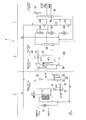
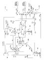
- FIG. 1 is a system diagram showing the overall configuration of a liquid fuel synthesis system including an embodiment of the hydrocarbon synthesis reaction apparatus of the present invention. It is a systematic diagram which shows schematic structure of the principal part of the hydrocarbon synthesis reaction apparatus shown in FIG.
- FIG. 1 is a system diagram showing the overall configuration of a liquid fuel synthesis system for carrying out an embodiment of a start-up method for a hydrocarbon synthesis reaction apparatus of the present invention.
- a liquid fuel synthesis system (hydrocarbon synthesis reaction system) 1 is a plant facility that executes a GTL process for converting a hydrocarbon feedstock such as natural gas into liquid fuel.
- the liquid fuel synthesis system 1 includes a synthesis gas generation unit 3, an FT synthesis unit (hydrocarbon synthesis reaction apparatus) 5, and an upgrading unit 7.
- the synthesis gas generation unit 3 reforms natural gas that is a hydrocarbon raw material to produce synthesis gas containing carbon monoxide gas and hydrogen gas.
- the FT synthesis unit 5 generates a liquid hydrocarbon compound from the produced synthesis gas by an FT synthesis reaction.
- the upgrading unit 7 hydrogenates and refines liquid hydrocarbon compounds synthesized by the FT synthesis reaction to produce liquid fuel and other products (naphtha, kerosene, light oil, wax, etc.).
- liquid fuel and other products no part of the FT synthesis unit 5
- components of each unit will be described.
- the synthesis gas generation unit 3 includes, for example, a desulfurization reactor 10, a reformer 12, an exhaust heat boiler 14, gas-liquid separators 16 and 18, a decarboxylation device 20, and a hydrogen separation device 26.
- the desulfurization reactor 10 is composed of a hydrodesulfurization apparatus or the like and removes sulfur components from natural gas as a raw material.
- the reformer 12 reforms the natural gas supplied from the desulfurization reactor 10 to produce a synthesis gas containing carbon monoxide gas (CO) and hydrogen gas (H 2 ) as main components.
- the exhaust heat boiler 14 recovers the exhaust heat of the synthesis gas generated in the reformer 12 and generates high-pressure steam.
- the gas-liquid separator 16 separates water heated by heat exchange with the synthesis gas in the exhaust heat boiler 14 into a gas (high-pressure steam) and a liquid.
- the gas-liquid separator 18 removes the condensate from the synthesis gas cooled by the exhaust heat boiler 14 and supplies the gas to the decarboxylation device 20.
- the decarboxylation device 20 includes an absorption tower 22 and a regeneration tower 24.
- the absorption tower 22 the carbon dioxide gas contained in the synthesis gas supplied from the gas-liquid separator 18 is absorbed by the absorption liquid.
- the regeneration tower 24 the absorbing liquid that has absorbed the carbon dioxide gas diffuses the carbon dioxide gas, and the absorbent is regenerated.
- the hydrogen separation device 26 separates a part of the hydrogen gas contained in the synthesis gas from the synthesis gas from which the carbon dioxide gas has been separated by the decarbonation device 20.
- the decarboxylation device 20 may not be provided depending on circumstances.
- the reformer 12 for example, natural gas is reformed by carbon dioxide and steam using the steam / carbon dioxide reforming method represented by the following chemical reaction formulas (1) and (2), and carbon monoxide gas A high-temperature synthesis gas mainly composed of hydrogen gas is produced.
- the reforming method in the reformer 12 is not limited to the steam / carbon dioxide reforming method.
- steam reforming method, partial oxidation reforming method using oxygen (POX), autothermal reforming method (ATR) which is a combination of partial oxidation reforming method and steam reforming method, carbon dioxide gas reforming method, etc. It can also be used.
- the hydrogen separator 26 is provided on a branch line branched from a main pipe connecting the decarbonator 20 or the gas-liquid separator 18 and the bubble column reactor 30.
- the hydrogen separator 26 can be constituted by, for example, a hydrogen PSA (Pressure Swing Adsorption) device that performs adsorption and desorption of hydrogen using a pressure difference.
- This hydrogen PSA apparatus has adsorbents (zeolite adsorbent, activated carbon, alumina, silica gel, etc.) in a plurality of adsorption towers (not shown) arranged in parallel.
- the hydrogen gas separation method in the hydrogen separator 26 is not limited to the pressure fluctuation adsorption method using the hydrogen PSA device.
- a hydrogen storage alloy adsorption method, a membrane separation method, or a combination thereof may be used.
- the hydrogen storage alloy method is, for example, a hydrogen storage alloy having the property of adsorbing / releasing hydrogen by being cooled / heated (TiFe, LaNi 5 , TiFe 0.7 to 0.9 Mn 0.3 to 0.1 , Alternatively, TiMn 1.5 or the like) is used to separate hydrogen gas.
- a hydrogen storage alloy method for example, in a plurality of adsorption towers containing a hydrogen storage alloy, hydrogen adsorption by cooling the hydrogen storage alloy and hydrogen release by heating the hydrogen storage alloy are alternately repeated. Thereby, hydrogen gas in the synthesis gas can be separated and recovered.
- the membrane separation method is a method of separating hydrogen gas having excellent membrane permeability from a mixed gas using a membrane made of a polymer material such as aromatic polyimide. Since this membrane separation method does not require a phase change to be separated, the energy required for operation is small and the running cost is low. Further, since the structure of the membrane separation apparatus is simple and compact, the equipment cost is low and the required area of the equipment is small. Further, the separation membrane has no driving device and has a wide stable operation range, so that there is an advantage that maintenance management is easy.
- the FT synthesis unit 5 includes, for example, a bubble column reactor (reaction vessel) 30, a gas / liquid separator 31, a gas / liquid separator 32, a gas / liquid separator 33, and a first rectifying tower 34. ing.
- the bubble column reactor 30 synthesizes a liquid hydrocarbon compound from the synthesis gas produced by the synthesis gas generation unit 3, that is, carbon monoxide gas and hydrogen gas, by an FT synthesis reaction.
- the gas-liquid separator 31 separates water heated through the cooling pipe 35 disposed in the bubble column reactor 30 into water vapor (medium pressure steam) and liquid.
- the gas-liquid separator 32 is connected to the primary filter 37 in the bubble column reactor 30 and separates the gas component contained in the liquid hydrocarbon compound that has passed through the primary filter 37.
- the gas-liquid separator 33 is connected to the top of the bubble column reactor 30 and separates the liquid hydrocarbon compound and the gas containing the unreacted synthesis gas by cooling the unreacted synthesis gas and the gaseous hydrocarbon compound. To do. Since this gas contains unnecessary components such as methane in the system, a part of the gas is discharged out of the system from the off-gas discharge passage 39 as off-gas.
- the first fractionator 34 fractionates the liquid hydrocarbon compound supplied from the bubble column reactor 30 via the gas-liquid separator 32 into each fraction.
- the bubble column reactor 30 is an example of a reaction vessel that synthesizes a liquid hydrocarbon compound from synthesis gas, and is used as a reaction vessel for FT synthesis that synthesizes a liquid hydrocarbon compound from synthesis gas by an FT synthesis reaction.
- the bubble column reactor 30 is, for example, a bubble column type slurry bed reactor in which a slurry mainly composed of catalyst particles and medium oil (medium liquid, liquid hydrocarbon) is accommodated inside a column type container. Composed.
- the bubble column reactor 30 synthesizes a gaseous or liquid hydrocarbon compound from a synthesis gas by an FT synthesis reaction.
- the synthesis gas as the raw material gas is supplied as bubbles from the sparger at the bottom of the bubble column reactor 30, and the catalyst particles are suspended in the medium oil. Pass through the slurry. Then, as shown in the following chemical reaction formula (3) in the suspended state, the hydrogen gas contained in the synthesis gas and the carbon monoxide gas react to synthesize a hydrocarbon compound.
- CO conversion rate the ratio of the carbon monoxide gas consumed in the reactor to the carbon monoxide gas (CO) supplied to the FT synthesis unit 5
- This CO conversion rate depends on the molar flow rate of the carbon monoxide gas (syngas CO molar flow rate) in the gas flowing into the FT synthesis unit 5 per unit time and from the FT synthesis unit 5 through the off-gas discharge channel 39 per unit time. It is calculated as a percentage from the molar flow rate of carbon monoxide gas (off-gas CO molar flow rate) in the off-gas extracted. That is, the CO conversion rate is obtained by the following equation (4).
- the bubble column reactor 30 is a heat exchanger type in which a cooling pipe 35 is disposed.
- water Boiler ⁇ ⁇ ⁇ Feed Water
- the reaction heat of the FT synthesis reaction can be recovered as medium pressure steam by heat exchange between the slurry and water. ing.
- the upgrading unit 7 includes, for example, a wax fraction hydrocracking reactor 50, a middle fraction hydrotreating reactor 52, a naphtha fraction hydrotreating reactor 54, and gas-liquid separators 56, 58, 60. And a second rectifying column 70 and a naphtha stabilizer 72.
- the wax fraction hydrocracking reactor 50 is connected to the bottom of the first rectifying column 34.
- the middle distillate hydrotreating reactor 52 is connected to the center of the first rectifying column 34.
- the naphtha fraction hydrotreating reactor 54 is connected to the top of the first rectifying column 34.
- the gas-liquid separators 56, 58 and 60 are provided corresponding to the hydrogenation reactors 50, 52 and 54, respectively.
- the second rectification column 70 fractionates the liquid hydrocarbon compound supplied from the gas-liquid separators 56 and 58.
- the naphtha stabilizer 72 rectifies the liquid hydrocarbon compound of the naphtha fraction supplied from the gas-liquid separator 60 and fractionated from the second fractionator 70. As a result, the naphtha stabilizer 72 discharges butane and lighter components than butane as off-gas, and collects components having 5 or more carbon atoms as naphtha of the product.
- the liquid fuel synthesis system 1 is supplied with natural gas (main component is CH 4 ) as a hydrocarbon feedstock from an external natural gas supply source (not shown) such as a natural gas field or a natural gas plant.
- the synthesis gas generation unit 3 reforms the natural gas to produce a synthesis gas (a mixed gas containing carbon monoxide gas and hydrogen gas as main components).
- the natural gas is introduced into the desulfurization reactor 10 together with the hydrogen gas separated by the hydrogen separator 26.
- the sulfur content contained in the natural gas is converted into hydrogen sulfide by the introduced hydrogen gas and the hydrodesulfurization catalyst.
- the produced hydrogen sulfide is adsorbed and removed by a desulfurizing agent such as ZnO.
- the natural gas (which may contain carbon dioxide) desulfurized in this way is generated in carbon dioxide (CO 2 ) gas supplied from a carbon dioxide supply source (not shown) and the exhaust heat boiler 14. After being mixed with water vapor, it is supplied to the reformer 12.
- the natural gas is reformed by carbon dioxide and steam by the steam / carbon dioxide reforming method described above, and a high-temperature synthesis gas mainly composed of carbon monoxide gas and hydrogen gas is produced.
- burner fuel gas and air (air) provided in the reformer 12 are supplied to the reformer 12.
- the heat of combustion of the fuel gas in the burner covers the reaction heat necessary for the steam / carbon dioxide gas reforming reaction, which is an endothermic reaction.
- the high-temperature synthesis gas (for example, 900 ° C., 2.0 MPaG) produced in the reformer 12 in this way is supplied to the exhaust heat boiler 14 and exchanges heat with water passing through the exhaust heat boiler 14. It is cooled (for example, 400 ° C.).
- the exhaust heat of the synthesis gas is recovered with water.
- the water heated by the synthesis gas in the exhaust heat boiler 14 is supplied to the gas-liquid separator 16.
- the water heated by the synthesis gas is separated into high-pressure steam (for example, 3.4 to 10.0 MPaG) and water in the gas-liquid separator 16.
- the separated high-pressure steam is supplied to the reformer 12 or other external device, and the separated water is returned to the exhaust heat boiler 14.
- the synthesis gas cooled in the exhaust heat boiler 14 is supplied to the absorption tower 22 of the decarbonation apparatus 20 or the bubble column reactor 30 after the condensed liquid is separated and removed in the gas-liquid separator 18. Is done.
- the carbon dioxide contained in the synthesis gas is absorbed by the absorption liquid stored in the absorption tower 22, and the carbon dioxide gas is removed from the synthesis gas.
- the absorption liquid that has absorbed carbon dioxide gas in the absorption tower 22 is discharged from the absorption tower 22 and introduced into the regeneration tower 24.
- the absorbing solution introduced into the regeneration tower 24 is heated, for example, with steam and stripped to release carbon dioxide.
- the released carbon dioxide gas is discharged from the regeneration tower 24, introduced into the reformer 12, and reused in the reforming reaction.
- the synthesis gas produced by the synthesis gas generation unit 3 is supplied to the bubble column reactor 30 of the FT synthesis unit 5.
- the synthesis gas supplied to the bubble column reactor 30 is converted into an FT synthesis reaction by a first compressor (not shown) provided in a pipe connecting the decarboxylation device 20 and the bubble column reactor 30.
- the pressure is increased to a suitable pressure (for example, about 3.6 MPaG).
- a part of the synthesis gas from which the carbon dioxide gas is separated by the decarboxylation device 20 is also supplied to the hydrogen separation device 26.
- the hydrogen gas contained in the synthesis gas is separated by the adsorption and desorption (hydrogen PSA) using the pressure difference as described above.
- the separated hydrogen is subjected to various hydrogen utilization reactions in which a predetermined reaction is performed using hydrogen in the liquid fuel synthesizing system 1 from a gas holder (not shown) or the like via a compressor (not shown). It is continuously supplied to the apparatus (for example, desulfurization reactor 10, wax fraction hydrocracking reactor 50, middle fraction hydrotreating reactor 52, naphtha fraction hydrotreating reactor 54, etc.).
- the FT synthesis unit 5 synthesizes a liquid hydrocarbon compound from the synthesis gas produced by the synthesis gas generation unit 3 by an FT synthesis reaction.
- the synthesis gas from which the carbon dioxide gas has been separated in the decarboxylation device 20 is introduced into the bubble column reactor 30 and passes through the slurry containing the catalyst accommodated in the bubble column reactor 30.
- the carbon monoxide gas and the hydrogen gas contained in the synthesis gas react with each other by the above-described FT synthesis reaction to generate a hydrocarbon compound.
- the reaction heat of the FT synthesis reaction is recovered by the water passing through the cooling pipe 35 of the bubble column reactor 30, and the water heated by the reaction heat is vaporized to become steam.
- This water vapor is supplied to the gas-liquid separator 31 and separated into condensed water and gas, and the water is returned to the cooling pipe 35, and the gas is externally supplied as medium pressure steam (for example, 1.0 to 2.5 MPaG). Supplied to the device.
- medium pressure steam for example, 1.0 to 2.5 MPaG
- the liquid hydrocarbon compound synthesized in the bubble column reactor 30 is discharged from the central portion of the bubble column reactor 30 with the catalyst particles removed by the primary filter 37, and gas-liquid separation is performed.
- a gas component is separated from the introduced liquid hydrocarbon compound.
- the separated liquid hydrocarbon compound is introduced into the first rectification column 34.
- a gas by-product containing the synthesis gas that has not reacted in the FT synthesis reaction and the gaseous hydrocarbon compound produced by the FT synthesis reaction is discharged.
- the gas by-product discharged from the bubble column reactor 30 is introduced into the gas-liquid separator 33.
- the introduced gas by-product is cooled and separated into a condensed liquid hydrocarbon compound and a gas component.
- the separated liquid hydrocarbon compound is discharged from the gas-liquid separator 33 and introduced into the first rectifying column 34.
- the separated gas component is discharged from the gas-liquid separator 33 and a part thereof is reintroduced into the bubble column reactor 30.
- unreacted synthesis gas (CO and H 2 ) contained in the reintroduced gas is reused for the FT synthesis reaction.
- a part of the gas discharged from the gas-liquid separator 33 is discharged as off-gas from the off-gas discharge passage 39 and used as fuel, or fuel equivalent to LPG (liquefied petroleum gas) is discharged from this gas. It is collected.
- the liquid hydrocarbon compound (having various carbon numbers) supplied from the bubble column reactor 30 through the gas-liquid separator 32 as described above is converted into a naphtha fraction (boiling point is about Fractionated into middle distillate (boiling point about 150-360 ° C.) and wax fraction (boiling point over about 360 ° C.).
- the liquid hydrocarbon compound (mainly C 22 or more) of the wax fraction discharged from the bottom of the first fractionator 34 is introduced into the wax fraction hydrocracking reactor 50.
- the middle distillate liquid hydrocarbon compound (mainly C 11 to C 21 ) corresponding to kerosene / light oil discharged from the center of the first fractionator 34 is introduced into the middle distillate hydrotreating reactor 52. .
- the liquid hydrocarbon compound (mainly C 5 to C 10 ) of the naphtha fraction discharged from the top of the first rectifying column 34 is introduced into the naphtha fraction hydrotreating reactor 54.
- Wax fraction hydrocracking reactor 50 carbon atoms discharged from the bottom of high wax fraction of liquid hydrocarbon compounds of the first fractionator 34 (approximately C 22 or more), from the hydrogen separator 26 Hydrocracking using the supplied hydrogen gas to reduce the carbon number to 21 or less.
- this hydrocracking reaction the C—C bond of a hydrocarbon compound having a large number of carbon atoms is broken. Thereby, a hydrocarbon compound having a large number of carbon atoms is converted into a hydrocarbon compound having a small number of carbon atoms.
- a linear saturated hydrocarbon compound normal paraffin
- isoparaffin is hydroisomerized to form a branched saturated hydrocarbon compound (isoparaffin).
- the reaction to produce is also advanced. Thereby, the low-temperature fluidity
- the product containing the liquid hydrocarbon compound hydrocracked and discharged from the wax fraction hydrocracking reactor 50 is introduced into the gas-liquid separator 56 and separated into a gas and a liquid.
- the separated liquid hydrocarbon compound is introduced into the second rectification column 70, and the separated gas component (including hydrogen gas) is separated into the middle distillate hydrotreating reactor 52 and the naphtha distillate hydrotreating reaction. Introduced into the vessel 54.
- the middle fraction of liquid hydrocarbon compounds carbon atoms ejected from the central portion of the first fractionator 34 is equivalent to the kerosene and gas oil is medium (approximately C 11 ⁇ C 21 ) is hydrorefined.
- the hydrogen gas supplied from the hydrogen separator 26 through the wax distillate hydrocracking reactor 50 is used for hydrotreating.
- an olefin contained in the liquid hydrocarbon compound is hydrogenated to produce a saturated hydrocarbon compound
- an oxygen-containing compound such as an alcohol contained in the liquid hydrocarbon compound is hydrogenated. Deoxygenated and converted to saturated hydrocarbon compound and water.
- a hydroisomerization reaction in which a linear saturated hydrocarbon compound (normal paraffin) is isomerized and converted to a branched saturated hydrocarbon compound (isoparaffin) proceeds, Improves low-temperature fluidity required as fuel oil.
- the product containing the hydrorefined liquid hydrocarbon compound is separated into a gas and a liquid by a gas-liquid separator 58.
- the separated liquid hydrocarbon compound is introduced into the second rectification column 70, and the gas component (including hydrogen gas) is reused in the hydrogenation reaction.
- the naphtha fraction hydrotreating reactor 54 the upper ejected fewer naphtha fraction of liquid hydrocarbon compounds carbons of the first fractionator 34 (approximately of C 10 or less) is hydrotreated.
- the hydrogen gas supplied from the hydrogen separator 26 via the wax fraction hydrocracking reactor 50 is used for hydrotreating.
- the hydrorefining reaction of the naphtha fraction mainly hydrogenation of olefins and hydrodeoxygenation of oxygen-containing compounds such as alcohols proceed.
- the product containing the hydrorefined liquid hydrocarbon compound is separated into a gas and a liquid by the gas-liquid separator 60.
- the separated liquid hydrocarbon compound is introduced into the naphtha stabilizer 72, and the separated gas component (including hydrogen gas) is reused in the hydrogenation reaction.
- the wax fraction hydrocracking reactor 50 and the middle distillate hydrotreating reactor 52 C 10 The following hydrocarbon compounds the supplied liquid hydrocarbon compounds from (boiling point Is lower than about 150 ° C., kerosene (boiling point is about 150 to 250 ° C.), light oil (boiling point is about 250 to 360 ° C.), and undecomposed wax content (boiling point) from the wax fraction hydrocracking reactor 50. (Over about 360 ° C.). An undecomposed wax fraction is obtained from the bottom of the second rectification tower 70 and is recycled upstream of the wax fraction hydrocracking reactor 50. Kerosene and light oil are discharged from the center of the second rectifying tower 70. On the other hand, hydrocarbon compounds of C 10 or less are discharged from the top of the second rectifying column 70 and introduced into the naphtha stabilizer 72.
- the hydrocarbon compound of C 10 or less supplied from the naphtha fraction hydrotreating reactor 54 and fractionated in the second rectifying column 70 is distilled to obtain a naphtha as a product. (C 5 -C 10 ) is obtained.
- high-purity naphtha is discharged from the bottom of the naphtha stabilizer 72.
- offgas carbon number of target products mainly composed of hydrocarbon compounds equal to or less than a predetermined number (C 4 or less) is discharged. This off gas is used as a fuel gas, or fuel equivalent to LPG is recovered from this off gas.
- FIG. 2 is a system diagram showing a schematic configuration of a main part of the FT synthesis unit (hydrocarbon synthesis reaction apparatus) 5 shown in FIG.
- a communication pipe 41 extends through the side wall of the bubble column reactor 30 to the outside and is connected to the gas-liquid separator 32.
- a filtration valve 44 is interposed in the communication pipe 41.
- FIG. 2 only one primary filter 37 is displayed, but in this embodiment, the primary filters 37 are arranged in a plurality of groups, and a filtration valve 44 and a backwash valve 95 described later are provided for each group. It is connected.
- a pressure adjusting valve 81a on the pressurization side and a pressure adjusting valve 81b on the depressurization side are connected to the pipe extending from the top of the gas-liquid separator 32.
- the gas liquid The internal pressure of the separator 32 is adjusted so as to have a predetermined differential pressure with respect to the pressure in the bubble column reactor 30. As a result, the slurry liquid level in the bubble column reactor 30 is maintained at a constant height during operation.
- a communication pipe 83 extends from the bottom of the gas-liquid separator 32, and the tip of the communication pipe 83 is connected to the gas-liquid separator 84.
- a secondary filter 85 and a flow rate adjusting valve 86 are interposed in the communication pipe 83. Further, the flow rate of the liquid hydrocarbon compound flowing in the communication pipe 83 is adjusted so that the liquid level in the gas-liquid separator 32 is kept constant by the flow rate adjusting valve 86.
- a pressure-adjusting pressure adjusting valve 87a and a pressure-reducing pressure adjusting valve 87b are connected to the pipe extending from the top of the gas-liquid separator 84. By opening and closing these pressure adjusting valves 87a, 87b, the gas-liquid is controlled. The internal pressure of the separator 84 is adjusted.
- a communication pipe 88 extends from the bottom of the gas-liquid separator 84, and the front end of the communication pipe 88 is connected to the backwash drum 89.
- a backwash pump 90 and a flow rate adjusting valve 91 are interposed in the communication pipe 88.
- the liquid hydrocarbon compound is transferred from the gas-liquid separator 84 to the backwash drum 89 by the backwash pump 90. Further, the flow rate of the liquid hydrocarbon compound flowing through the communication pipe 88 is adjusted by the flow rate adjusting valve 91, whereby the liquid level in the backwash drum 89 is kept constant.
- the piping extending from the top of the backwash drum 89 is connected with a pressure adjusting valve 92a on the pressurizing side and a pressure adjusting valve 92b or 92c on the depressurizing side, and these pressure adjusting valves 92a, 92b and 92c are opened and closed.
- the internal pressure of the backwash drum 89 is adjusted.
- a communication pipe 93 extends from the bottom of the backwash drum 89, and the tip of the communication pipe 93 is connected to a portion between the primary filter 37 and the filtration valve 44 of the communication pipe 41.
- a flow rate adjusting valve 94 and a backwash valve 95 are interposed in the communication pipe 93.
- the flow rate of the liquid hydrocarbon compound flowing in the communication pipe 93 is adjusted by the flow rate adjusting valve 94.
- the bubble column reactor 30 is provided with pulverized catalyst particle discharging means 100 for discharging the powdered catalyst particles present in the slurry in the bubble column reactor 30 to the outside of the bubble column reactor 30.
- the powdered catalyst particle discharging means 100 includes an external circulation path 101 that draws the slurry in the bubble column reactor 30 to the outside of the bubble column reactor 30, and a first classifier 104 interposed in the external circulation path 101. And a powdered particle separator 110 connected to the upper part of the first classifier 104 via an outflow passage 108.
- the proximal end of the external circulation path 101 is connected to the middle part of the bubble column reactor 30, and the distal end of the external circulation path 101 is connected to the bottom of the bubble column reactor 30.
- an adjustment valve 102, a gas-liquid separator 103, a first classifier 104, a flow rate adjustment valve 105, and an opening / closing valve 106 are sequentially provided in the external circulation path 101 from the proximal end side to the distal end side.
- the regulating valve 102 and the on-off valve 106 communicate or shut off the external circulation path 101 in the bubble column reactor 30, and are opened during normal operation, and the external circulation path 101 is opened in the bubble column reactor. 30 is in communication.
- the flow rate adjustment valve 105 adjusts the flow rate of the slurry flowing in the external circulation path 101.
- the gas-liquid separator 103 separates the gas component contained in the slurry discharged from the bubble column reactor 30.
- the top of the gas-liquid separator 103 communicates with the top of the bubble column reactor 30 through the communication pipe 107a.
- the first classifying device 104 uses a difference in sedimentation speed for the catalyst contained in the slurry separated by the gas-liquid separator 103, so that the particle size is smaller than that of the powdered catalyst particles. Separate into large catalyst particles.
- the upper part of the first classifier 104 has a cone-like structure that spreads upward.
- the first classifier 104 is provided with a plurality of slurry extraction nozzles 104a to 104d arranged in the height direction, and is connected to the slurry outflow passage 108 via the slurry extraction passages 108a to 108d. ing.
- slurry extraction nozzles 104a to 104d four sets of slurry extraction nozzles 104a to 104d and slurry extraction passages 108a to 108d are provided as an example. However, it is important to provide a plurality of these, and the number is limited to four sets. Not what you want.
- the upper part of the first classifier 104 is connected to the pulverized particle capturing unit 109 via the slurry outflow passage 108.
- the pulverized particle capture unit 109 is connected to the pulverized particle separation device 110 that captures the pulverized catalyst particles from the slurry, and is connected to the pulverized particle separation device 110 to collect the slurry containing the captured catalyst particles.
- An extraction path 111 is provided.
- the separation system of the powdered particle separator 110 is not specified. For example, a filter filtration method, a gravity sedimentation method, a cyclone method, a centrifugal separation method, a magnetic separation method, and the like can be considered.
- a communication tube 112 extends from the powdered particle capturing unit 109, and the tip of the communication tube 112 is connected to the gas-liquid separator 84.
- the communication pipe 112 is provided with a flow rate adjusting valve (outflow rate adjusting unit) 113, and by operating the flow rate adjusting valve 113, the outflow rate of the liquid hydrocarbon compound flowing through the communication pipe 112 is adjusted. .
- the massive particle discharging means 120 includes a second classifier 121 that separates larger particles according to the difference in sedimentation speed, and an extraction path 122 for recovering the slurry containing the separated and concentrated aggregated catalyst particles.
- the upper part of the second classifier 121 has a cone-like structure spreading upward.
- a communication pipe 123 branched from the communication pipe 88 is connected to the second classifier 121, and the liquid hydrocarbon compound is blown upward in the second classifier 121.
- the communication pipe 123 is provided with a flow rate adjustment valve (supply flow rate adjustment unit) 124, and the flow rate adjustment valve 124 adjusts the flow rate of the liquid hydrocarbon compound supplied to the second classifier 121.
- the catalyst particle adding means 130 includes a slurry preparation tank 131 containing new catalyst particles, and a supply path 137 connecting the preparation tank 131 and the bubble column reactor 30.
- the preparation tank 131 is connected to a communication pipe 134 branched from the communication pipe 88 and provided with a regulating valve 135, and an introduction path 133 for introducing new catalyst particles, and further includes a stirrer 132.
- a pressure adjustment valve 136a on the pressurization side and a pressure adjustment valve 136b on the pressure reduction side are connected to the pipe extending from the top of the preparation tank 131.
- the internal pressure of the preparation tank 131 is adjusted to be a predetermined differential pressure with respect to the pressure in the bubble column reactor 30, and the regulating valve 138 is opened and closed.
- the slurry in the preparation tank 131 is supplied to the bubble column reactor 30 through the supply path 137 that includes the valve 139.
- the operation of the FT synthesis unit 5 configured as described above will be described.
- Most of the liquid hydrocarbon compound produced by the FT synthesis reaction in the bubble column reactor 30 is removed when passing through the primary filter 37, and is led to the gas-liquid separator 32 through the communication pipe 41.
- the liquid hydrocarbon compound discharged after the gas component is removed by the gas-liquid separator 32 further passes through the secondary filter 85 and then sent to the gas-liquid separator 84.
- the secondary filter 85 is for preventing the catalyst outflow to the subsequent stage due to the damage of the primary filter 37 or the like.
- a part of the liquid hydrocarbon compound sent to the gas-liquid separator 84 is sent to the backwash drum 89 by the backwash pump 90.
- the liquid hydrocarbon compound sent to the backwash drum 89 is subjected to the primary filter 37 through the communication pipe 93 and a part of the communication pipe 41 in a state where the backwash valve 95 is opened and the filtration valve 44 is closed. Sent to. As a result, the primary filter 37 is backwashed. During normal operation, the backwash valve 95 is closed and the filtration valve 44 is opened, and slurry filtration by the primary filter 37 is performed.
- the slurry that has passed through the primary filter 37 is taken out to the outside of the bubble column reactor 30 through the external circulation path 101 and is pulverized among the catalyst particles contained in the slurry by the pulverized catalyst particle discharging means 100. Only the catalyst particles are removed.
- the slurry is returned to the bubble column reactor 30 again via the external circulation path 101. That is, a part of the slurry in the bubble column reactor 30 is usually led to the gas-liquid separator 103 via the external circulation path 101 because the regulating valve 102 and the on-off valve 106 are opened.
- the slurry is further guided to the first classifier 104.
- the catalyst contained in the slurry is separated into pulverized catalyst particles and catalyst particles having a larger particle size than the pulverized catalyst particles due to the difference in sedimentation speed.
- the fine catalyst particles separated from the slurry are guided to the pulverized particle separation device 110 of the pulverized particle capturing unit 109 from the outflow passage 108 together with the liquid hydrocarbon compound, and are captured by the pulverized particle separation device 110.
- the liquid hydrocarbon compound from which the fine catalyst particles have been removed by the pulverized particle separation device 110 is guided to the gas-liquid separator 84 via the communication pipe 112, and the captured fine catalyst particles are extracted from the extraction path 111. Then, the catalyst is discharged as a fine catalyst concentrated slurry 114.
- the particle catalyst separated by the first classifier 104 is returned to the bottom of the bubble column reactor 30 through the external circulation path 101 together with the liquid hydrocarbon compound.
- the FT synthesis unit 5 includes the pulverized catalyst particle discharging means 100, and the pulverized catalyst particles in the slurry by the pulverized catalyst particle discharging means 100 are continuously bubbled. It discharges outside the reactor 30. For this reason, it is possible to prevent the amount of the minute catalyst present in the bubble column reactor 30 from being remarkably increased even when the catalyst is more than expected or is pulverized for a long time. . As a result, it is possible to prevent the primary filter 37 from being blocked due to a large amount of powdered catalyst particles. For this reason, the synthesized liquid hydrocarbon compound can be separated from the catalyst by the primary filter 37 and stably discharged to the outside of the bubble column reactor 30.
- the FT synthesis unit 5 positively discharges the catalyst particles pulverized as described above to the outside of the bubble column reactor 30, it is not discharged from the top of the bubble column reactor 30.
- the amount of fine catalyst particles entrained in the gas by-product containing the reaction gas and gaseous hydrocarbon compound can also be reduced.
- the amount of fine catalyst particles contained in light oil (light oil) is also reduced, and in the latter stage of the light oil treatment system, elements that cause catalyst poisoning in the process of hydrocracking light oil and the like are mixed. As a result, the product yield is improved.
- the communication pipe 112 is provided with a flow rate adjusting valve 113, and the inside of the communication pipe 112 is controlled depending on the operation of the flow rate adjusting valve 113 and which of the slurry extraction nozzles 104a to 104d and the slurry extraction paths 108a to 108d is selected.
- the outflow rate of the flowing liquid hydrocarbon compound, and thus the particle size of the catalyst particles separated by the first classifier 104 can be changed. That is, when the extraction height is set to a low position and the slurry flow rate from the first classifier 104 is increased, catalyst particles having a relatively large diameter flow out to the outflow passage 108, and the extraction height is set to a high position. When the outflow rate of the slurry from the first classifier 104 is slowed, catalyst particles having a relatively small diameter flow out into the outflow passage 108.
- the catalyst particles that have been agglomerated and increased in weight in the bubble column reactor 30 are discharged out of the bubble column reactor 30 by the block particle discharging means 120.
- the second classifier 121 located at the bottom of the bubble column reactor 30 the massive particles separated by utilizing the settling velocity difference are discharged as the massive particle concentrated slurry 125 through the massive particle extraction path 122.
- the second classifier 121 is in a state filled with the catalyst slurry in the same manner as in the bubble column reactor 30, but the upper part of the second classifier 121 having a cone shape spreading upward and the communication pipe 123 are connected to each other.
- the particle size and weight of the deteriorated catalyst particles to be separated and recovered can be adjusted by the method of supplying the liquid hydrocarbon compound so as to blow upward in the second classifier 121. That is, by adjusting the flow rate of the liquid hydrocarbon compound supplied to the second classifier 121 by the operation of the flow rate adjustment valve 124 provided in the communication pipe 123, the particles in the second classifier 121 are easily floated. Therefore, the easily settled massive particles are concentrated on the bottom of the second classifier 121, separated from the catalyst particles smaller than the massive particles, and separated and discharged.
- the FT synthesis unit 5 includes the lump particle discharging means 120, and the lumped particle discharging means 120 converts the agglomerated deteriorated catalyst present in the bubble column reactor 30 to the bubble column reaction. To the outside of the vessel 30.
- the slurry containing new catalyst particles is supplied to the bubble column reactor 30 by the catalyst particle adding means 130.
- a liquid hydrocarbon compound is supplied to the preparation tank 131 via the communication pipe 88 and new catalyst particles are supplied via the charging path 133, and a slurry having a predetermined concentration is prepared by stirring with the stirrer 132.
- the preparation tank 131 in which slurry of a predetermined concentration is prepared is maintained at a pressure higher than that of the bubble column reactor 30 by operating the pressure adjusting valves 136a and 136b, and the supply path is provided by opening the adjusting valve 138 and the on-off valve 139. Through 137, the slurry in the preparation tank 131 is pumped to the bubble column reactor 30. Since the rapid supply of slurry may affect the operation of the bubble column reactor 30, the supply amount is adjusted by adjusting the opening of the adjustment valve 138.
- the FT synthesis unit 5 includes the catalyst particle adding means 130, and the catalyst particle adding means 130 supplies a slurry containing new catalyst particles to the bubble column reactor 30.
- a synthesis gas mainly composed of carbon monoxide gas and hydrogen gas is brought into contact with a slurry obtained by suspending a solid catalyst in a liquid hydrocarbon compound, and a liquid hydrocarbon compound is formed by a Fischer-Tropsch reaction.
- a reaction vessel for synthesis; a filter provided in the reaction vessel for separating the liquid hydrocarbon compound from the catalyst; and pulverized catalyst particles of the solid catalyst in the slurry are discharged to the outside of the reaction vessel.
- the present invention relates to a hydrocarbon synthesis reaction apparatus provided with a pulverized catalyst particle discharging means. According to the present invention, the liquid hydrocarbon compound produced in the reaction vessel can be stably discharged to the outside of the reaction vessel.
Landscapes
- Chemical & Material Sciences (AREA)
- Oil, Petroleum & Natural Gas (AREA)
- Engineering & Computer Science (AREA)
- Chemical Kinetics & Catalysis (AREA)
- General Chemical & Material Sciences (AREA)
- Organic Chemistry (AREA)
- Production Of Liquid Hydrocarbon Mixture For Refining Petroleum (AREA)
- Separation Of Solids By Using Liquids Or Pneumatic Power (AREA)
- Devices And Processes Conducted In The Presence Of Fluids And Solid Particles (AREA)
- Organic Low-Molecular-Weight Compounds And Preparation Thereof (AREA)
Abstract
Description
本願は、2013年3月26日に、日本に出願された特願2013-065192号に基づき優先権を主張し、その内容をここに援用する。
これにより、粉化した微小な触媒粒子を連続的にまたは定期的に捕獲することができる。なお、微小な触媒粒子を分離された液体炭化水素化合物は、反応容器内に戻して再利用しても良いし、反応容器内のフィルタ逆洗用の液体として利用しても良い。
塊状化して重量を増した劣化触媒は、塊状粒子排出手段によって定期的に反応容器の外部へ排出される。このため、スラリー中を沈降しやすい塊状の劣化触媒が反応容器内に濃縮することを防止できる。この結果、触媒が不均一に分散してスラリーの流動性が低下するのを抑制できる。
また、スラリー中を沈降しやすい塊状化した触媒粒子が反応容器内に濃縮するのを防止し、触媒が不均一に分散してスラリーの流動性が低下するのを抑制できる。
図1は本発明の炭化水素合成反応装置のスタートアップ方法の一実施形態を実施する液体燃料合成システムの全体構成を示す系統図である。図1に示すように、液体燃料合成システム(炭化水素合成反応システム)1は、天然ガス等の炭化水素原料を液体燃料に転換するGTLプロセスを実行するプラント設備である。この液体燃料合成システム1は、合成ガス生成ユニット3と、FT合成ユニット(炭化水素合成反応装置)5と、アップグレーディングユニット7とから構成される。合成ガス生成ユニット3は、炭化水素原料である天然ガスを改質して一酸化炭素ガスと水素ガスを含む合成ガスを製造する。FT合成ユニット5は、製造された合成ガスからFT合成反応により液体の炭化水素化合物を生成する。アップグレーディングユニット7は、FT合成反応により合成された液体の炭化水素化合物を水素化・精製して液体燃料その他の製品(ナフサ、灯油、軽油、ワックス等)を製造する。以下、これら各ユニットの構成要素について説明する。
合成ガス生成ユニット3は、例えば、脱硫反応器10と、改質器12と、排熱ボイラー14と、気液分離器16および18と、脱炭酸装置20と、水素分離装置26とを備えている。脱硫反応器10は、水素化脱硫装置等で構成されて原料である天然ガスから硫黄成分を除去する。改質器12は、脱硫反応器10から供給された天然ガスを改質して、一酸化炭素ガス(CO)と水素ガス(H2)とを主成分として含む合成ガスを製造する。排熱ボイラー14は、改質器12にて生成した合成ガスの排熱を回収して高圧スチームを発生する。気液分離器16は、排熱ボイラー14において合成ガスとの熱交換により加熱された水を気体(高圧スチーム)と液体とに分離する。気液分離器18は、排熱ボイラー14にて冷却された合成ガスから凝縮分を除去し気体分を脱炭酸装置20に供給する。

FT合成ユニット5は、例えば、気泡塔型反応器(反応容器)30と、気液分離器31と、気液分離器32と、気液分離器33と、第1精留塔34とを備えている。気泡塔型反応器30は、上記合成ガス生成ユニット3で製造された合成ガス、即ち、一酸化炭素ガスと水素ガスとからFT合成反応により液体炭化水素化合物を合成する。


液体燃料合成システム1には、天然ガス田又は天然ガスプラントなどの外部の天然ガス供給源(図示せず。)から、炭化水素原料としての天然ガス(主成分がCH4)が供給される。上記合成ガス生成ユニット3は、この天然ガスを改質して合成ガス(一酸化炭素ガスと水素ガスを主成分とする混合ガス)を製造する。
このとき、排熱ボイラー14において合成ガスにより加熱された水は気液分離器16に供給される。そして、この合成ガスにより加熱された水は、気液分離器16において高圧スチーム(例えば3.4~10.0MPaG)と、水とに分離される。分離された高圧スチームは、改質器12または他の外部装置に供給され、分離された水は排熱ボイラー14に戻される。
気泡塔型反応器30の塔頂からは、FT合成反応において反応しなかった合成ガスと、FT合成反応により生成した気体炭化水素化合物と、を含む気体副生成物が排出される。気泡塔型反応器30から排出された気体副生成物は、気液分離器33に導入される。気液分離器33では、導入された気体副生成物が冷却され、凝縮した液体炭化水素化合物と、ガス分とに分離される。分離された液体炭化水素化合物は、気液分離器33から排出され、第1精留塔34に導入される。
分離された液体炭化水素化合物は、第2精留塔70に導入され、気体分(水素ガスを含む。)は、上記水素化反応に再利用される。
図2は図1に示すFT合成ユニット(炭化水素合成反応装置)5の要部の概略構成を示す系統図である。
気泡塔型反応器30内に設けられた一次フィルタ37からは連通管41が気泡塔型反応器30の側壁を貫通して外部まで延びて気液分離器32に接続されている。連通管41には濾過弁44が介装されている。また、図2では一次フィルタ37はひとつしか表示されていないが、この実施形態では、一次フィルタ37は複数群に配列されていて、各群毎に濾過弁44および後述する逆洗弁95がそれぞれ接続されている。
気液分離器84の頂部から延びる配管には加圧側の圧力調整弁87aと減圧側の圧力調整弁87bが接続されており、これら圧力調整弁87a、87bが開閉操作されることによって、気液分離器84の内部圧力が調整される。
逆洗ドラム89の底部からは連通管93が延びており、連通管93の先端は前記連通管41の一次フィルタ37と濾過弁44との間の部分に接続されている。連通管93には流量調整弁94と逆洗弁95がそれぞれ介装されている。流量調整弁94によって連通管93内を流れる液体炭化水素化合物の流量が調整される。逆洗弁95が開閉操作されることによって、逆洗ドラム89から連通管41へ液体炭化水素化合物の流れが許容あるいは遮断される。
調整弁102及び開閉弁106は外部循環路101を気泡塔型反応器30内に連通あるいは遮断操作するものであり、通常の運転時には、開状態とされて外部循環路101を気泡塔型反応器30内に連通させている。また、流量調整弁105は、外部循環路101内を流れるスラリーの流量を調整する。
第一分級装置104は、気液分離器103で分離されたスラリーに含まれる触媒を、沈降速度差を利用することにより、粉化した触媒粒子と、その粉化した触媒粒子よりも粒径が大きな触媒粒子とに分離する。第一分級装置104の上部は上向きに広がるコーン状の構造となっている。また、第一分級装置104の内部には、高さ方向に配列された複数のスラリー抜出ノズル104a~dが備えられており、スラリー抜出路108a~dを介してスラリー流出路108に接続されている。尚、図2中では一例として4セットのスラリー抜出ノズル104a~dとスラリー抜出路108a~dとが設けられているが、これらは複数設けることが肝要であり、その数は4セットに限定するものではない。
調製槽131の頂部から延びる配管には加圧側の圧力調整弁136aと減圧側の圧力調整弁136bが接続されている。これら圧力調整弁136a、136bが開閉操作されることによって、調製槽131の内部圧力が気泡塔型反応器30内の圧力に対して所定の差圧となるように調整され、調整弁138、開閉弁139を介装する供給路137を通じて、調製槽131のスラリーが気泡塔型反応器30に供給される。
気泡塔型反応器30内でFT合成反応により生成された液体炭化水素化合物は、一次フィルタ37を通過するときに大半の触媒が除去され、連通管41を通して気液分離器32に導かれる。この気液分離器32でガス分を取り除かれた後に排出される液体炭化水素化合物は、さらに二次フィルタ85を通過し、その後気液分離器84に送られる。二次フィルタ85は、一次フィルタ37の破損等による後段への触媒流出を防ぐためのものである。
気液分離器84に送られた液体炭化水素化合物の一部は、逆洗ポンプ90によって逆洗ドラム89に送られる。逆洗ドラム89に送られた液体炭化水素化合物は、逆洗弁95が開操作されかつ濾過弁44が閉操作された状態で、連通管93及び連通管41の一部を介して一次フィルタ37に送られる。これにより、一次フィルタ37の逆洗が行なわれる。
なお、通常の運転時では、逆洗弁95が閉操作されかつ濾過弁44が開操作された状態となって、一次フィルタ37によるスラリー濾過が行なわれる。
すなわち、気泡塔型反応器30内のスラリーの一部は、通常、調整弁102及び開閉弁106が開操作されているため、外部循環路101を介して気液分離器103へ導かれる。ここで、スラリー中のガス分が除去された後、該スラリーはさらに第一分級装置104へ導かれる。この第一分級装置104で、スラリーに含まれる触媒は、沈降速度差により、粉化した触媒粒子と、その粉化した触媒粒子よりも粒径が大きな触媒粒子とに分離される。
本発明によれば、反応容器内部で生成された液体炭化水素化合物を、反応容器の外部へ安定して払い出すことができる。
5 FT合成ユニット(炭化水素合成反応装置)
7 アップグレーディングユニット
30 気泡塔型反応器(反応容器)
32 気液分離器
37 一次フィルタ(フィルタ)
44 濾過弁
84 気液分離器
85 二次フィルタ
89 逆洗ドラム
90 逆洗ポンプ
95 逆洗弁
100 粉化触媒粒子排出手段
101 外部循環路
103 気液分離器
104 第一分級装置
104a~d スラリー抜出ノズル
105 流量調整弁
108 流出路
109 粉化粒子捕獲部
110 粉化粒子分離装置
111 抜出路
112 連通管
113 流量調整弁(流出速度調整部)
114 微小触媒濃縮スラリー
120 塊状粒子排出手段
121 第二分級装置
122 塊状粒子抜出路(排出路)
123 連通管
124 流量調整弁(供給流量調整部)
125 塊状粒子濃縮スラリー
130 触媒粒子追加手段
131 調製槽
132 攪拌機
133 投入路
137 供給路
138 調整弁
Claims (8)
- 一酸化炭素ガス及び水素ガスを主成分とする合成ガスを、液体炭化水素化合物中に固体触媒を懸濁させてなるスラリーに接触させてフィッシャー・トロプッシュ反応により液体炭化水素化合物を合成する反応容器と、
前記反応容器内に設けられ、前記触媒から前記液体炭化水素化合物を分離させるフィルタと、
前記スラリー中の前記固体触媒のうち粉化した触媒粒子を前記反応容器の外部へ排出させる粉化触媒粒子排出手段を備える炭化水素合成反応装置。 - 前記粉化触媒粒子排出手段は、
前記スラリー中の前記固体触媒から、前記粉化した触媒粒子を、液中における粒子の沈降速度差を利用して分離する第一分級装置と、
前記第一分級装置で分離された前記粉化した触媒粒子を、前記液体炭化水素化合物とともに前記第一分級装置の外部へ流出させる流出路と、
前記流出路に設けられ、前記粉化した触媒粒子を捕獲する粉化粒子分離装置とを含む請求項1に記載の炭化水素合成反応装置。 - 前記流出路中の、前記粉化した触媒粒子を含む前記液体炭化水素化合物の流出速度を調整する流出速度調整部をさらに備え、
前記第一分級装置の上部がコーン状に形成され、
前記コーン状に形成された前記第一分級装置の内部に、高さ方向に配列された複数のスラリー抜出ノズルが設けられる請求項2に記載の炭化水素合成反応装置。 - 前記粉化粒子分離装置に、フィルタ濾過方式、重力沈降方式、サイクロン方式、遠心分離方式、磁気分離方式のいずれかの方式が採用される請求項2に記載の炭化水素合成反応装置。
- 前記スラリー中の前記固体触媒のうち塊状化した触媒粒子を前記反応容器の外部へ排出させる塊状粒子排出手段をさらに備える請求項1から4のいずれか一項に記載の炭化水素合成反応装置。
- 前記塊状粒子排出手段は、
前記スラリー中の前記固体触媒から、前記塊状化した触媒粒子を、液中における粒子の沈降速度差を利用して分離する第二分級装置と、
前記第二分級装置で分離された前記塊状化した触媒粒子を、前記第二分級装置の外部へ排出する排出路とを含む請求項5に記載の炭化水素合成反応装置。 - 前記第二分級装置に前記液体炭化水素化合物を供給する連通管中の、前記液体炭化水素化合物の供給流量を調整する供給流量調整部をさらに備え、
前記第二分級装置の上部がコーン状に形成され、
前記第二分級装置に供給される液体炭化水素化合物が、前記コーン状に形成された前記第二分級装置の内部で上向きに吹き出される請求項6に記載の炭化水素合成反応装置。 - 前記反応容器に、新品の触媒粒子を前記反応容器内の前記スラリーに追加する触媒粒子追加手段をさらに備える請求項1から7のいずれか一項に記載の炭化水素合成反応装置。
Priority Applications (10)
| Application Number | Priority Date | Filing Date | Title |
|---|---|---|---|
| EA201591600A EA032165B1 (ru) | 2013-03-26 | 2014-03-19 | Аппарат для осуществления реакции синтеза углеводородов |
| EP14774229.0A EP2980189B8 (en) | 2013-03-26 | 2014-03-19 | Hydrocarbon synthesis apparatus |
| AU2014246133A AU2014246133B2 (en) | 2013-03-26 | 2014-03-19 | Hydrocarbon synthesis reaction apparatus |
| BR112015024169-7A BR112015024169B1 (pt) | 2013-03-26 | 2014-03-19 | Aparelho de reação de síntese de hidrocarboneto |
| CN201480017842.6A CN105051158B (zh) | 2013-03-26 | 2014-03-19 | 烃合成反应装置 |
| MYPI2015703047A MY182588A (en) | 2013-03-26 | 2014-03-19 | Hydrocarbon synthesis reaction apparatus |
| CA2906435A CA2906435C (en) | 2013-03-26 | 2014-03-19 | Hydrocarbon synthesis reaction apparatus |
| US14/778,636 US9688918B2 (en) | 2013-03-26 | 2014-03-19 | Hydrocarbon synthesis reaction apparatus |
| AP2015008725A AP2015008725A0 (en) | 2013-03-26 | 2014-03-19 | Hydrocarbon synthesis reaction apparatus |
| ZA2015/06979A ZA201506979B (en) | 2013-03-26 | 2015-09-18 | Hydrocarbon synthesis reaction apparatus |
Applications Claiming Priority (2)
| Application Number | Priority Date | Filing Date | Title |
|---|---|---|---|
| JP2013-065192 | 2013-03-26 | ||
| JP2013065192A JP6071691B2 (ja) | 2013-03-26 | 2013-03-26 | 炭化水素合成反応装置 |
Publications (1)
| Publication Number | Publication Date |
|---|---|
| WO2014156890A1 true WO2014156890A1 (ja) | 2014-10-02 |
Family
ID=51623869
Family Applications (1)
| Application Number | Title | Priority Date | Filing Date |
|---|---|---|---|
| PCT/JP2014/057553 Ceased WO2014156890A1 (ja) | 2013-03-26 | 2014-03-19 | 炭化水素合成反応装置 |
Country Status (12)
| Country | Link |
|---|---|
| US (1) | US9688918B2 (ja) |
| EP (1) | EP2980189B8 (ja) |
| JP (1) | JP6071691B2 (ja) |
| CN (1) | CN105051158B (ja) |
| AP (1) | AP2015008725A0 (ja) |
| AU (1) | AU2014246133B2 (ja) |
| BR (1) | BR112015024169B1 (ja) |
| CA (1) | CA2906435C (ja) |
| EA (1) | EA032165B1 (ja) |
| MY (1) | MY182588A (ja) |
| WO (1) | WO2014156890A1 (ja) |
| ZA (1) | ZA201506979B (ja) |
Cited By (1)
| Publication number | Priority date | Publication date | Assignee | Title |
|---|---|---|---|---|
| EP3144045A1 (de) * | 2015-09-18 | 2017-03-22 | L'AIR LIQUIDE, Société Anonyme pour l'Etude et l'Exploitation des Procédés Georges Claude | Verfahren und vorrichtung zum abtrennen von partikeln einer bestimmten grösse aus einer suspension |
Families Citing this family (4)
| Publication number | Priority date | Publication date | Assignee | Title |
|---|---|---|---|---|
| KR102755509B1 (ko) * | 2019-04-09 | 2025-01-17 | 주식회사 디엔솔루션즈 | 가공영역에 팔레트를 구비하는 머시닝 센터 및 이를 이용한 공작물 가공방법 |
| CN110102226A (zh) * | 2019-04-26 | 2019-08-09 | 河南百优福生物能源有限公司 | 一种生物质热解液沸腾床反应器中颗粒移出工艺和装置 |
| CN110026135B (zh) * | 2019-04-26 | 2022-04-19 | 河南百优福生物能源有限公司 | 一种生物质热解液沸腾床反应器中颗粒移出方法和装置 |
| CN110013803B (zh) * | 2019-04-26 | 2022-06-10 | 河南百优福生物能源有限公司 | 一种生物质热解液沸腾床反应器中颗粒移出方法和系统 |
Citations (7)
| Publication number | Priority date | Publication date | Assignee | Title |
|---|---|---|---|---|
| WO2009113614A1 (ja) * | 2008-03-14 | 2009-09-17 | 独立行政法人石油天然ガス・金属鉱物資源機構 | フィッシャー・トロプシュ合成粗油からの磁性粒子の除去方法、およびフィッシャー・トロプシュ合成粗油の製造方法 |
| WO2009113613A1 (ja) * | 2008-03-14 | 2009-09-17 | 新日鉄エンジニアリング株式会社 | 炭化水素化合物の合成反応システム、及び粉化粒子の除去方法 |
| JP2010038396A (ja) | 2008-08-01 | 2010-02-18 | Takasago Thermal Eng Co Ltd | 既設天井設置機器の交換方法 |
| WO2010038396A1 (ja) * | 2008-09-30 | 2010-04-08 | 独立行政法人石油天然ガス・金属鉱物資源機構 | 炭化水素化合物合成反応ユニット及びその運転方法 |
| WO2011034036A1 (ja) * | 2009-09-16 | 2011-03-24 | 独立行政法人石油天然ガス・金属鉱物資源機構 | 炭化水素油の製造方法および合成反応システム |
| WO2012036377A2 (ko) * | 2010-09-17 | 2012-03-22 | 한국화학연구원 | 합성가스로부터 탄화수소를 제조하기 위한 반응장치 |
| WO2012132920A1 (ja) * | 2011-03-28 | 2012-10-04 | 独立行政法人石油天然ガス・金属鉱物資源機構 | 炭化水素の製造方法 |
Family Cites Families (4)
| Publication number | Priority date | Publication date | Assignee | Title |
|---|---|---|---|---|
| JPS5316933B2 (ja) * | 1973-06-18 | 1978-06-05 | ||
| JPS51143954A (en) * | 1975-06-04 | 1976-12-10 | Shichiro Shoda | Method of classifying dispersed substance and apparatus for classifyin g substance used for the same method |
| JPS5993515A (ja) | 1982-11-17 | 1984-05-30 | Aisin Seiki Co Ltd | タ−ボチヤ−ジヤ用軸受装置 |
| CN100548459C (zh) | 2006-07-31 | 2009-10-14 | 中国石油化工股份有限公司 | 一种浆态床反应设备及其应用方法 |
-
2013
- 2013-03-26 JP JP2013065192A patent/JP6071691B2/ja active Active
-
2014
- 2014-03-19 EA EA201591600A patent/EA032165B1/ru not_active IP Right Cessation
- 2014-03-19 CN CN201480017842.6A patent/CN105051158B/zh not_active Expired - Fee Related
- 2014-03-19 US US14/778,636 patent/US9688918B2/en active Active
- 2014-03-19 AU AU2014246133A patent/AU2014246133B2/en active Active
- 2014-03-19 AP AP2015008725A patent/AP2015008725A0/xx unknown
- 2014-03-19 BR BR112015024169-7A patent/BR112015024169B1/pt not_active IP Right Cessation
- 2014-03-19 CA CA2906435A patent/CA2906435C/en active Active
- 2014-03-19 EP EP14774229.0A patent/EP2980189B8/en active Active
- 2014-03-19 WO PCT/JP2014/057553 patent/WO2014156890A1/ja not_active Ceased
- 2014-03-19 MY MYPI2015703047A patent/MY182588A/en unknown
-
2015
- 2015-09-18 ZA ZA2015/06979A patent/ZA201506979B/en unknown
Patent Citations (7)
| Publication number | Priority date | Publication date | Assignee | Title |
|---|---|---|---|---|
| WO2009113614A1 (ja) * | 2008-03-14 | 2009-09-17 | 独立行政法人石油天然ガス・金属鉱物資源機構 | フィッシャー・トロプシュ合成粗油からの磁性粒子の除去方法、およびフィッシャー・トロプシュ合成粗油の製造方法 |
| WO2009113613A1 (ja) * | 2008-03-14 | 2009-09-17 | 新日鉄エンジニアリング株式会社 | 炭化水素化合物の合成反応システム、及び粉化粒子の除去方法 |
| JP2010038396A (ja) | 2008-08-01 | 2010-02-18 | Takasago Thermal Eng Co Ltd | 既設天井設置機器の交換方法 |
| WO2010038396A1 (ja) * | 2008-09-30 | 2010-04-08 | 独立行政法人石油天然ガス・金属鉱物資源機構 | 炭化水素化合物合成反応ユニット及びその運転方法 |
| WO2011034036A1 (ja) * | 2009-09-16 | 2011-03-24 | 独立行政法人石油天然ガス・金属鉱物資源機構 | 炭化水素油の製造方法および合成反応システム |
| WO2012036377A2 (ko) * | 2010-09-17 | 2012-03-22 | 한국화학연구원 | 합성가스로부터 탄화수소를 제조하기 위한 반응장치 |
| WO2012132920A1 (ja) * | 2011-03-28 | 2012-10-04 | 独立行政法人石油天然ガス・金属鉱物資源機構 | 炭化水素の製造方法 |
Non-Patent Citations (1)
| Title |
|---|
| See also references of EP2980189A4 |
Cited By (3)
| Publication number | Priority date | Publication date | Assignee | Title |
|---|---|---|---|---|
| EP3144045A1 (de) * | 2015-09-18 | 2017-03-22 | L'AIR LIQUIDE, Société Anonyme pour l'Etude et l'Exploitation des Procédés Georges Claude | Verfahren und vorrichtung zum abtrennen von partikeln einer bestimmten grösse aus einer suspension |
| WO2017046263A1 (en) * | 2015-09-18 | 2017-03-23 | L'Air Liquide Société Anonyme pour l'Etude et l'Exploitation des Procédés Georges Claude | Process and apparatus for separating particles of a certain order of magnitude from a suspension |
| CN108136282A (zh) * | 2015-09-18 | 2018-06-08 | 乔治洛德方法研究和开发液化空气有限公司 | 用于从悬浊液中分离特定数量级的颗粒的方法和设备 |
Also Published As
| Publication number | Publication date |
|---|---|
| BR112015024169B1 (pt) | 2020-05-26 |
| JP6071691B2 (ja) | 2017-02-01 |
| MY182588A (en) | 2021-01-25 |
| EA032165B1 (ru) | 2019-04-30 |
| CN105051158A (zh) | 2015-11-11 |
| CN105051158B (zh) | 2017-05-03 |
| US20160046870A1 (en) | 2016-02-18 |
| BR112015024169A2 (pt) | 2017-07-18 |
| EP2980189B8 (en) | 2018-08-29 |
| EP2980189A4 (en) | 2016-12-21 |
| EP2980189B1 (en) | 2018-07-04 |
| ZA201506979B (en) | 2017-01-25 |
| CA2906435A1 (en) | 2014-10-02 |
| EP2980189A1 (en) | 2016-02-03 |
| CA2906435C (en) | 2017-04-18 |
| AU2014246133B2 (en) | 2016-07-28 |
| AP2015008725A0 (en) | 2015-09-30 |
| AU2014246133A1 (en) | 2015-10-01 |
| EA201591600A1 (ru) | 2016-01-29 |
| JP2014189603A (ja) | 2014-10-06 |
| US9688918B2 (en) | 2017-06-27 |
Similar Documents
| Publication | Publication Date | Title |
|---|---|---|
| JP5568462B2 (ja) | 炭化水素化合物の合成反応システム、及び粉化粒子の除去方法 | |
| CN103298558B (zh) | 催化剂回收系统、烃合成反应装置、烃合成反应系统及催化剂回收方法 | |
| CN102165042B (zh) | 催化剂分离系统 | |
| CN102575173B (zh) | 烃合成反应装置、烃合成反应系统以及液体烃的回收方法 | |
| CN102165037B (zh) | 烃化合物合成反应单元及其运转方法 | |
| JP6071691B2 (ja) | 炭化水素合成反応装置 | |
| CN102549111B (zh) | 烃合成反应装置、烃合成反应系统以及烃合成反应方法 | |
| CN103443249B (zh) | 烃合成反应装置、其启动方法及烃合成反应系统 | |
| CN102165038A (zh) | 烃合成反应装置、烃合成反应系统以及烃合成方法 | |
| CA2867990C (en) | Start-up method of bubble column slurry bed reactor | |
| CN102348783B (zh) | 催化剂分离系统 |
Legal Events
| Date | Code | Title | Description |
|---|---|---|---|
| WWE | Wipo information: entry into national phase |
Ref document number: 201480017842.6 Country of ref document: CN |
|
| 121 | Ep: the epo has been informed by wipo that ep was designated in this application |
Ref document number: 14774229 Country of ref document: EP Kind code of ref document: A1 |
|
| WWE | Wipo information: entry into national phase |
Ref document number: 2014774229 Country of ref document: EP |
|
| ENP | Entry into the national phase |
Ref document number: 2906435 Country of ref document: CA |
|
| WWE | Wipo information: entry into national phase |
Ref document number: 14778636 Country of ref document: US |
|
| WWE | Wipo information: entry into national phase |
Ref document number: IDP00201506084 Country of ref document: ID |
|
| WWE | Wipo information: entry into national phase |
Ref document number: 201591600 Country of ref document: EA |
|
| ENP | Entry into the national phase |
Ref document number: 2014246133 Country of ref document: AU Date of ref document: 20140319 Kind code of ref document: A |
|
| REG | Reference to national code |
Ref country code: BR Ref legal event code: B01A Ref document number: 112015024169 Country of ref document: BR |
|
| NENP | Non-entry into the national phase |
Ref country code: DE |
|
| ENP | Entry into the national phase |
Ref document number: 112015024169 Country of ref document: BR Kind code of ref document: A2 Effective date: 20150921 |