WO2014157095A1 - 給電装置、車両及び非接触給電システム - Google Patents
給電装置、車両及び非接触給電システム Download PDFInfo
- Publication number
- WO2014157095A1 WO2014157095A1 PCT/JP2014/058095 JP2014058095W WO2014157095A1 WO 2014157095 A1 WO2014157095 A1 WO 2014157095A1 JP 2014058095 W JP2014058095 W JP 2014058095W WO 2014157095 A1 WO2014157095 A1 WO 2014157095A1
- Authority
- WO
- WIPO (PCT)
- Prior art keywords
- power
- power supply
- vehicle
- battery
- contact
- Prior art date
- Legal status (The legal status is an assumption and is not a legal conclusion. Google has not performed a legal analysis and makes no representation as to the accuracy of the status listed.)
- Ceased
Links
Images




Classifications
-
- B—PERFORMING OPERATIONS; TRANSPORTING
- B60—VEHICLES IN GENERAL
- B60L—PROPULSION OF ELECTRICALLY-PROPELLED VEHICLES; SUPPLYING ELECTRIC POWER FOR AUXILIARY EQUIPMENT OF ELECTRICALLY-PROPELLED VEHICLES; ELECTRODYNAMIC BRAKE SYSTEMS FOR VEHICLES IN GENERAL; MAGNETIC SUSPENSION OR LEVITATION FOR VEHICLES; MONITORING OPERATING VARIABLES OF ELECTRICALLY-PROPELLED VEHICLES; ELECTRIC SAFETY DEVICES FOR ELECTRICALLY-PROPELLED VEHICLES
- B60L53/00—Methods of charging batteries, specially adapted for electric vehicles; Charging stations or on-board charging equipment therefor; Exchange of energy storage elements in electric vehicles
- B60L53/10—Methods of charging batteries, specially adapted for electric vehicles; Charging stations or on-board charging equipment therefor; Exchange of energy storage elements in electric vehicles characterised by the energy transfer between the charging station and the vehicle
- B60L53/12—Inductive energy transfer
- B60L53/122—Circuits or methods for driving the primary coil, e.g. supplying electric power to the coil
-
- H—ELECTRICITY
- H02—GENERATION; CONVERSION OR DISTRIBUTION OF ELECTRIC POWER
- H02J—ELECTRIC POWER NETWORKS; CIRCUIT ARRANGEMENTS OR SYSTEMS FOR SUPPLYING OR DISTRIBUTING ELECTRIC POWER; SYSTEMS FOR STORING ELECTRIC ENERGY
- H02J7/00—Circuit arrangements for charging or discharging batteries or for supplying loads from batteries
-
- B—PERFORMING OPERATIONS; TRANSPORTING
- B60—VEHICLES IN GENERAL
- B60L—PROPULSION OF ELECTRICALLY-PROPELLED VEHICLES; SUPPLYING ELECTRIC POWER FOR AUXILIARY EQUIPMENT OF ELECTRICALLY-PROPELLED VEHICLES; ELECTRODYNAMIC BRAKE SYSTEMS FOR VEHICLES IN GENERAL; MAGNETIC SUSPENSION OR LEVITATION FOR VEHICLES; MONITORING OPERATING VARIABLES OF ELECTRICALLY-PROPELLED VEHICLES; ELECTRIC SAFETY DEVICES FOR ELECTRICALLY-PROPELLED VEHICLES
- B60L53/00—Methods of charging batteries, specially adapted for electric vehicles; Charging stations or on-board charging equipment therefor; Exchange of energy storage elements in electric vehicles
- B60L53/10—Methods of charging batteries, specially adapted for electric vehicles; Charging stations or on-board charging equipment therefor; Exchange of energy storage elements in electric vehicles characterised by the energy transfer between the charging station and the vehicle
- B60L53/12—Inductive energy transfer
- B60L53/126—Methods for pairing a vehicle and a charging station, e.g. establishing a one-to-one relation between a wireless power transmitter and a wireless power receiver
-
- B—PERFORMING OPERATIONS; TRANSPORTING
- B60—VEHICLES IN GENERAL
- B60L—PROPULSION OF ELECTRICALLY-PROPELLED VEHICLES; SUPPLYING ELECTRIC POWER FOR AUXILIARY EQUIPMENT OF ELECTRICALLY-PROPELLED VEHICLES; ELECTRODYNAMIC BRAKE SYSTEMS FOR VEHICLES IN GENERAL; MAGNETIC SUSPENSION OR LEVITATION FOR VEHICLES; MONITORING OPERATING VARIABLES OF ELECTRICALLY-PROPELLED VEHICLES; ELECTRIC SAFETY DEVICES FOR ELECTRICALLY-PROPELLED VEHICLES
- B60L53/00—Methods of charging batteries, specially adapted for electric vehicles; Charging stations or on-board charging equipment therefor; Exchange of energy storage elements in electric vehicles
- B60L53/10—Methods of charging batteries, specially adapted for electric vehicles; Charging stations or on-board charging equipment therefor; Exchange of energy storage elements in electric vehicles characterised by the energy transfer between the charging station and the vehicle
- B60L53/14—Conductive energy transfer
-
- B—PERFORMING OPERATIONS; TRANSPORTING
- B60—VEHICLES IN GENERAL
- B60L—PROPULSION OF ELECTRICALLY-PROPELLED VEHICLES; SUPPLYING ELECTRIC POWER FOR AUXILIARY EQUIPMENT OF ELECTRICALLY-PROPELLED VEHICLES; ELECTRODYNAMIC BRAKE SYSTEMS FOR VEHICLES IN GENERAL; MAGNETIC SUSPENSION OR LEVITATION FOR VEHICLES; MONITORING OPERATING VARIABLES OF ELECTRICALLY-PROPELLED VEHICLES; ELECTRIC SAFETY DEVICES FOR ELECTRICALLY-PROPELLED VEHICLES
- B60L53/00—Methods of charging batteries, specially adapted for electric vehicles; Charging stations or on-board charging equipment therefor; Exchange of energy storage elements in electric vehicles
- B60L53/30—Constructional details of charging stations
- B60L53/305—Communication interfaces
-
- B—PERFORMING OPERATIONS; TRANSPORTING
- B60—VEHICLES IN GENERAL
- B60L—PROPULSION OF ELECTRICALLY-PROPELLED VEHICLES; SUPPLYING ELECTRIC POWER FOR AUXILIARY EQUIPMENT OF ELECTRICALLY-PROPELLED VEHICLES; ELECTRODYNAMIC BRAKE SYSTEMS FOR VEHICLES IN GENERAL; MAGNETIC SUSPENSION OR LEVITATION FOR VEHICLES; MONITORING OPERATING VARIABLES OF ELECTRICALLY-PROPELLED VEHICLES; ELECTRIC SAFETY DEVICES FOR ELECTRICALLY-PROPELLED VEHICLES
- B60L53/00—Methods of charging batteries, specially adapted for electric vehicles; Charging stations or on-board charging equipment therefor; Exchange of energy storage elements in electric vehicles
- B60L53/30—Constructional details of charging stations
- B60L53/31—Charging columns specially adapted for electric vehicles
-
- B—PERFORMING OPERATIONS; TRANSPORTING
- B60—VEHICLES IN GENERAL
- B60L—PROPULSION OF ELECTRICALLY-PROPELLED VEHICLES; SUPPLYING ELECTRIC POWER FOR AUXILIARY EQUIPMENT OF ELECTRICALLY-PROPELLED VEHICLES; ELECTRODYNAMIC BRAKE SYSTEMS FOR VEHICLES IN GENERAL; MAGNETIC SUSPENSION OR LEVITATION FOR VEHICLES; MONITORING OPERATING VARIABLES OF ELECTRICALLY-PROPELLED VEHICLES; ELECTRIC SAFETY DEVICES FOR ELECTRICALLY-PROPELLED VEHICLES
- B60L53/00—Methods of charging batteries, specially adapted for electric vehicles; Charging stations or on-board charging equipment therefor; Exchange of energy storage elements in electric vehicles
- B60L53/60—Monitoring or controlling charging stations
- B60L53/62—Monitoring or controlling charging stations in response to charging parameters, e.g. current, voltage or electrical charge
-
- B—PERFORMING OPERATIONS; TRANSPORTING
- B60—VEHICLES IN GENERAL
- B60L—PROPULSION OF ELECTRICALLY-PROPELLED VEHICLES; SUPPLYING ELECTRIC POWER FOR AUXILIARY EQUIPMENT OF ELECTRICALLY-PROPELLED VEHICLES; ELECTRODYNAMIC BRAKE SYSTEMS FOR VEHICLES IN GENERAL; MAGNETIC SUSPENSION OR LEVITATION FOR VEHICLES; MONITORING OPERATING VARIABLES OF ELECTRICALLY-PROPELLED VEHICLES; ELECTRIC SAFETY DEVICES FOR ELECTRICALLY-PROPELLED VEHICLES
- B60L53/00—Methods of charging batteries, specially adapted for electric vehicles; Charging stations or on-board charging equipment therefor; Exchange of energy storage elements in electric vehicles
- B60L53/60—Monitoring or controlling charging stations
- B60L53/66—Data transfer between charging stations and vehicles
-
- H—ELECTRICITY
- H02—GENERATION; CONVERSION OR DISTRIBUTION OF ELECTRIC POWER
- H02J—ELECTRIC POWER NETWORKS; CIRCUIT ARRANGEMENTS OR SYSTEMS FOR SUPPLYING OR DISTRIBUTING ELECTRIC POWER; SYSTEMS FOR STORING ELECTRIC ENERGY
- H02J50/00—Circuit arrangements or systems for wireless supply or distribution of electric power
- H02J50/10—Circuit arrangements or systems for wireless supply or distribution of electric power using inductive coupling
-
- H—ELECTRICITY
- H02—GENERATION; CONVERSION OR DISTRIBUTION OF ELECTRIC POWER
- H02J—ELECTRIC POWER NETWORKS; CIRCUIT ARRANGEMENTS OR SYSTEMS FOR SUPPLYING OR DISTRIBUTING ELECTRIC POWER; SYSTEMS FOR STORING ELECTRIC ENERGY
- H02J50/00—Circuit arrangements or systems for wireless supply or distribution of electric power
- H02J50/80—Circuit arrangements or systems for wireless supply or distribution of electric power involving the exchange of data, concerning supply or distribution of electric power, between transmitting devices and receiving devices
-
- H—ELECTRICITY
- H02—GENERATION; CONVERSION OR DISTRIBUTION OF ELECTRIC POWER
- H02J—ELECTRIC POWER NETWORKS; CIRCUIT ARRANGEMENTS OR SYSTEMS FOR SUPPLYING OR DISTRIBUTING ELECTRIC POWER; SYSTEMS FOR STORING ELECTRIC ENERGY
- H02J7/00—Circuit arrangements for charging or discharging batteries or for supplying loads from batteries
- H02J7/70—Circuit arrangements for charging or discharging batteries or for supplying loads from batteries characterised by the mechanical construction
-
- B—PERFORMING OPERATIONS; TRANSPORTING
- B60—VEHICLES IN GENERAL
- B60L—PROPULSION OF ELECTRICALLY-PROPELLED VEHICLES; SUPPLYING ELECTRIC POWER FOR AUXILIARY EQUIPMENT OF ELECTRICALLY-PROPELLED VEHICLES; ELECTRODYNAMIC BRAKE SYSTEMS FOR VEHICLES IN GENERAL; MAGNETIC SUSPENSION OR LEVITATION FOR VEHICLES; MONITORING OPERATING VARIABLES OF ELECTRICALLY-PROPELLED VEHICLES; ELECTRIC SAFETY DEVICES FOR ELECTRICALLY-PROPELLED VEHICLES
- B60L2250/00—Driver interactions
- B60L2250/16—Driver interactions by display
-
- B—PERFORMING OPERATIONS; TRANSPORTING
- B60—VEHICLES IN GENERAL
- B60L—PROPULSION OF ELECTRICALLY-PROPELLED VEHICLES; SUPPLYING ELECTRIC POWER FOR AUXILIARY EQUIPMENT OF ELECTRICALLY-PROPELLED VEHICLES; ELECTRODYNAMIC BRAKE SYSTEMS FOR VEHICLES IN GENERAL; MAGNETIC SUSPENSION OR LEVITATION FOR VEHICLES; MONITORING OPERATING VARIABLES OF ELECTRICALLY-PROPELLED VEHICLES; ELECTRIC SAFETY DEVICES FOR ELECTRICALLY-PROPELLED VEHICLES
- B60L53/00—Methods of charging batteries, specially adapted for electric vehicles; Charging stations or on-board charging equipment therefor; Exchange of energy storage elements in electric vehicles
- B60L53/10—Methods of charging batteries, specially adapted for electric vehicles; Charging stations or on-board charging equipment therefor; Exchange of energy storage elements in electric vehicles characterised by the energy transfer between the charging station and the vehicle
- B60L53/12—Inductive energy transfer
-
- H—ELECTRICITY
- H02—GENERATION; CONVERSION OR DISTRIBUTION OF ELECTRIC POWER
- H02J—ELECTRIC POWER NETWORKS; CIRCUIT ARRANGEMENTS OR SYSTEMS FOR SUPPLYING OR DISTRIBUTING ELECTRIC POWER; SYSTEMS FOR STORING ELECTRIC ENERGY
- H02J50/00—Circuit arrangements or systems for wireless supply or distribution of electric power
- H02J50/90—Circuit arrangements or systems for wireless supply or distribution of electric power involving detection or optimisation of position, e.g. alignment
-
- H—ELECTRICITY
- H02—GENERATION; CONVERSION OR DISTRIBUTION OF ELECTRIC POWER
- H02J—ELECTRIC POWER NETWORKS; CIRCUIT ARRANGEMENTS OR SYSTEMS FOR SUPPLYING OR DISTRIBUTING ELECTRIC POWER; SYSTEMS FOR STORING ELECTRIC ENERGY
- H02J7/00—Circuit arrangements for charging or discharging batteries or for supplying loads from batteries
- H02J7/70—Circuit arrangements for charging or discharging batteries or for supplying loads from batteries characterised by the mechanical construction
- H02J7/751—Circuit arrangements for charging or discharging batteries or for supplying loads from batteries characterised by the mechanical construction concerning the insertion or the connection of the batteries
-
- Y—GENERAL TAGGING OF NEW TECHNOLOGICAL DEVELOPMENTS; GENERAL TAGGING OF CROSS-SECTIONAL TECHNOLOGIES SPANNING OVER SEVERAL SECTIONS OF THE IPC; TECHNICAL SUBJECTS COVERED BY FORMER USPC CROSS-REFERENCE ART COLLECTIONS [XRACs] AND DIGESTS
- Y02—TECHNOLOGIES OR APPLICATIONS FOR MITIGATION OR ADAPTATION AGAINST CLIMATE CHANGE
- Y02T—CLIMATE CHANGE MITIGATION TECHNOLOGIES RELATED TO TRANSPORTATION
- Y02T10/00—Road transport of goods or passengers
- Y02T10/60—Other road transportation technologies with climate change mitigation effect
- Y02T10/70—Energy storage systems for electromobility, e.g. batteries
-
- Y—GENERAL TAGGING OF NEW TECHNOLOGICAL DEVELOPMENTS; GENERAL TAGGING OF CROSS-SECTIONAL TECHNOLOGIES SPANNING OVER SEVERAL SECTIONS OF THE IPC; TECHNICAL SUBJECTS COVERED BY FORMER USPC CROSS-REFERENCE ART COLLECTIONS [XRACs] AND DIGESTS
- Y02—TECHNOLOGIES OR APPLICATIONS FOR MITIGATION OR ADAPTATION AGAINST CLIMATE CHANGE
- Y02T—CLIMATE CHANGE MITIGATION TECHNOLOGIES RELATED TO TRANSPORTATION
- Y02T10/00—Road transport of goods or passengers
- Y02T10/60—Other road transportation technologies with climate change mitigation effect
- Y02T10/7072—Electromobility specific charging systems or methods for batteries, ultracapacitors, supercapacitors or double-layer capacitors
-
- Y—GENERAL TAGGING OF NEW TECHNOLOGICAL DEVELOPMENTS; GENERAL TAGGING OF CROSS-SECTIONAL TECHNOLOGIES SPANNING OVER SEVERAL SECTIONS OF THE IPC; TECHNICAL SUBJECTS COVERED BY FORMER USPC CROSS-REFERENCE ART COLLECTIONS [XRACs] AND DIGESTS
- Y02—TECHNOLOGIES OR APPLICATIONS FOR MITIGATION OR ADAPTATION AGAINST CLIMATE CHANGE
- Y02T—CLIMATE CHANGE MITIGATION TECHNOLOGIES RELATED TO TRANSPORTATION
- Y02T90/00—Enabling technologies or technologies with a potential or indirect contribution to GHG emissions mitigation
- Y02T90/10—Technologies relating to charging of electric vehicles
- Y02T90/12—Electric charging stations
-
- Y—GENERAL TAGGING OF NEW TECHNOLOGICAL DEVELOPMENTS; GENERAL TAGGING OF CROSS-SECTIONAL TECHNOLOGIES SPANNING OVER SEVERAL SECTIONS OF THE IPC; TECHNICAL SUBJECTS COVERED BY FORMER USPC CROSS-REFERENCE ART COLLECTIONS [XRACs] AND DIGESTS
- Y02—TECHNOLOGIES OR APPLICATIONS FOR MITIGATION OR ADAPTATION AGAINST CLIMATE CHANGE
- Y02T—CLIMATE CHANGE MITIGATION TECHNOLOGIES RELATED TO TRANSPORTATION
- Y02T90/00—Enabling technologies or technologies with a potential or indirect contribution to GHG emissions mitigation
- Y02T90/10—Technologies relating to charging of electric vehicles
- Y02T90/14—Plug-in electric vehicles
-
- Y—GENERAL TAGGING OF NEW TECHNOLOGICAL DEVELOPMENTS; GENERAL TAGGING OF CROSS-SECTIONAL TECHNOLOGIES SPANNING OVER SEVERAL SECTIONS OF THE IPC; TECHNICAL SUBJECTS COVERED BY FORMER USPC CROSS-REFERENCE ART COLLECTIONS [XRACs] AND DIGESTS
- Y02—TECHNOLOGIES OR APPLICATIONS FOR MITIGATION OR ADAPTATION AGAINST CLIMATE CHANGE
- Y02T—CLIMATE CHANGE MITIGATION TECHNOLOGIES RELATED TO TRANSPORTATION
- Y02T90/00—Enabling technologies or technologies with a potential or indirect contribution to GHG emissions mitigation
- Y02T90/10—Technologies relating to charging of electric vehicles
- Y02T90/16—Information or communication technologies improving the operation of electric vehicles
Definitions
- the present invention relates to a power feeding device, a vehicle, and a non-contact power feeding system.
- the charger is configured such that the power receiving terminal is electrically connected to an AC power source, AC power input from the power receiving terminal is converted into predetermined DC power, and the secondary battery is charged.
- a non-contact power receiving unit is configured to receive power from the AC power source in a non-contact manner by being magnetically coupled to the power transmission unit of the AC power source, and the non-contact power receiving unit is connected to the power conversion circuit of the charger. Then, the vehicle that compares the conductive received power and the non-contact received power, and controls the charger so as to execute charging using the larger one of the conductive received power and the non-contact received power based on the comparison result.
- a battery charger is disclosed (Patent Document 1).
- the problem to be solved by the present invention is that, when charging of a battery of a certain vehicle is requested by one power supply method, and there is a request for charging by the other power supply method, It is to provide a power feeding device, a vehicle, and a non-contact power feeding system that prevent charging from being restricted.
- the present invention is based on the power feeding method from the second vehicle to the other power feeding method while the battery of the first vehicle is charged by either the power feeding method by the non-contact power feeding unit or the contact power feeding method by the contact power feeding unit.
- the power supply according to one power supply method is continued and the power supply according to the other power supply method is waited to solve the above problem.
- the battery when a battery of one vehicle is charged with one power supply method and there is a request for charging with the other power supply method, the battery is charged with the other power supply method to charge first. Since the charging efficiency of the charged battery is not lowered, it is possible to prevent the charging from being restricted on the battery being charged.
- FIG. 1 is a block diagram of a non-contact power feeding system according to an embodiment of the present invention.
- the non-contact power feeding system of this example supplies power to the vehicle-side power receiving coil 31 in a non-contact manner at least by magnetic coupling from the power transmitting coil 11 of the power feeding device provided on the ground side. And it is a system which charges the battery 33 of the vehicle 3 with the electric power received with the receiving coil 31.
- FIG. The non-contact power supply system is a system that can supply power by two systems, that is, a system using non-contact power supply and a system using contact power supply. In the system method using contact power feeding, a charging cable is connected between the power feeding device 1 and the charging port 36 of the vehicle 3.
- the contactless power supply system is provided in a parking facility such as a parking lot for home use or a common facility such as parking on a highway.
- the non-contact power feeding system includes a vehicle 3 and a power feeding device 1.
- the power feeding device 1 is provided in a parking space where the vehicle 3 is parked, and is a unit on the ground side that supplies power by non-contact power feeding between coils when the vehicle 3 is parked at a predetermined parking position.
- the vehicle 3 is a vehicle 3 such as an electric vehicle or a plug-in hybrid vehicle that can charge a battery provided in the vehicle by a power source from the outside.
- the configurations of the power feeding device 1 and the vehicle 3 that constitute the non-contact power feeding system will be described.
- the vehicle 3 will be described as an electric vehicle.
- dotted arrows indicate signal lines between the controllers 10 and 30 and the configuration in the power feeding device 1 and the configuration in the vehicle 3, and the thick line indicates the battery 33 with the power of the AC power supply 2.
- the power line at the time of charging is shown, and the system type power line by contact power feeding and the system type power line by non-contact power feeding are shown.
- the power feeding device 1 includes a controller 10, a power transmission coil 11, a power unit 12, a current sensor 13, a charging connector 14, a charging cable 15, a relay switch 16, a current sensor 17, a communication device 18, and wireless communication.
- a unit 19, a display unit 20, and a memory 21 are provided.
- the controller 10 is a main controller for controlling the entire power supply apparatus 1.
- the power transmission coil 11 is a parallel circular coil for supplying electric power to the power receiving coil 31 provided on the vehicle 3 side in a non-contact manner, and is provided in a parking space provided with the non-contact power feeding device of this example. Is provided.
- the power unit 12 is a circuit for converting AC power transmitted from the AC power source 2 into high-frequency AC power and transmitting the AC power to the power transmission coil 11.
- a rectification unit a power factor correction circuit (PFC (Power Factor Correction) circuit)
- PFC Power Factor Correction
- the power unit 12 outputs desired power to the power transmission coil 11 by PWM control of the switching element of the inverter by the controller 10.
- the wiring electrically connected to the AC power supply 2 is branched by the wiring connected to the power unit 12 and the wiring connected to the relay switch 16.
- the current sensor 13 is connected to a branch wiring between the AC power supply 2 and the power unit 12 and detects a current flowing from the AC power supply 2 to the power unit 12.
- the current sensor 13 detects a current flowing from the AC power source 2 to the power unit 12 when charging the battery 33 of the vehicle 3 by the non-contact power feeding method.
- the detection value of the current sensor 13 is output to the controller 10.
- the charging connector 14 is a connector for connecting to the charging port 36 of the vehicle 3, and the charging connector 14 is provided at one end of the charging cable 15.
- the charging connector 14 serves as an output of the charging circuit on the power feeding device side that constitutes the contact power feeding method.
- the charging connector 14 is provided with a release switch that can be operated by the user. Then, when the charging connector 14 is fitted into the charging port 36 and the release switch is turned on, the charging port 36 and the charging cable 15 are electrically connected.
- the charging cable 15 is a wiring that connects the charging connector 14 and a contact power feeding charging circuit in the power feeding device 1.
- the relay switch 16 is a switch for switching electrical conduction and interruption from the AC power supply 2 to the charging connector 14, and is controlled by the controller 10. When charging the battery 33 of the vehicle 3 by the contact power feeding method, the relay switch 16 is turned on.
- the current sensor 17 is connected to a branch wiring between the AC power supply 2 and the relay switch 16.
- the current sensor 17 detects charging flowing from the AC power supply 2 to the relay switch when charging the battery 33 by the contact power feeding method.
- the detection value of the current sensor 17 is output to the controller 10.
- the communication device 18 is connected to the charging connector 14 via a communication line.
- the communication device 18 includes a power supply for low power and a switch (for communication).
- the communication line connected to the communication device 18 and the communication line on the vehicle side are electrically connected.
- These communication lines transmit and receive information on the battery 33 and information on the maximum output current of the power feeding apparatus 1 in the contact power feeding method between the controller 10 and the controller 30 when charging the battery 33 by the contact power feeding method.
- Signal line When the communication line on the vehicle side and the communication line on the power feeding device side are connected by fitting the charging connector and the charging port, the weak power source of the communication device 18 is connected to the vehicle side and the power feeding device side via the switch. Are added to the vehicle side switch (communication switch) and ground.
- the applied voltage of the communication line on the vehicle side changes by switching the communication switch of the communication device 18 on and off.
- the vehicle-side controller 30 acquires information from the voltage change caused by turning on and off the communication switch of the communication device 18.
- the communication device 18 performs pulse communication by switching the switch on and off.
- the switch of the communication device 18 turned on, the voltage of the communication line on the power feeding device 1 changes by switching on and off of the switch on the vehicle side. Information can be transmitted from the vehicle 3 to the power supply device 1.
- the communication device 18 also has a function of detecting connection of the charging connector 14 to the charging port 36 on the power feeding device 1 side.
- a voltage drop occurs on the communication line on the power feeding device 1 side. Therefore, the communication device 18 detects the voltage change, thereby detecting the connection of the charging connector 14. Can do.
- the wireless communication unit 19 is a transceiver that performs bidirectional communication with the wireless communication unit 39 provided on the vehicle 3 side.
- the communication frequency between the wireless communication unit 19 and the wireless communication unit 39 is set to a frequency different from the frequency used in the vehicle peripheral device such as intelligence ski. Even if communication is performed between the vehicles, the vehicle peripheral device is not easily affected by the communication.
- various wireless LAN systems are used for communication between the wireless communication unit 19 and the wireless communication unit 29.
- Wireless communication by the wireless communication units 19 and 26 is used in charge control by a non-contact power supply method.
- the display unit 20 is a display for displaying the state of charge control by the contact power supply method and the state of charge control by the non-contact power supply method, and is provided on the surface of the casing of the power supply device 1.
- the memory 21 records the identification information such as the registration number of the power feeding device 1, the identification information of the vehicle 3 acquired from the vehicle side at the time of non-contact power feeding, and the rated current value that can be output from the AC power source 2. It is a medium.
- the vehicle 3 includes a controller 30, a power receiving coil 31, a power receiving circuit unit 32, a battery 33, a sensor 34, a converter 35, a charging port 36, a connection detection device 37, a display unit 38, and a wireless communication unit. 39 and a memory 40.
- the controller 30 performs various controls in the EV system of the vehicle 3 as well as the charging control when charging the battery 33.
- the power receiving coil 31 is provided on the bottom surface (chassis) of the vehicle 3 and between the rear wheels. When the vehicle 3 is parked at a predetermined parking position, the power reception coil 31 is positioned above the power transmission coil 11 while maintaining a distance from the power transmission coil 11.
- the power receiving coil 31 is a circular coil parallel to the surface of the parking space.
- the power receiving circuit unit 32 is connected between the power receiving coil 31 and the battery 33, and has a circuit and a relay switch for converting AC power received by the power receiving coil into DC power.
- the relay switch is switched on and off based on the control of the controller 30. When charging the battery 33 by non-contact power feeding, the relay switch is turned on.
- the battery 33 is a secondary battery that outputs electric power to a motor (not shown) that is a power source of the vehicle 3 via an inverter (not shown).
- the battery 33 is configured by connecting a plurality of secondary batteries such as lithium ion batteries in series or in parallel.
- the battery 33 is electrically connected to the power receiving coil 31 via the power receiving circuit unit 32. Further, the battery 33 is connected to the converter 35.
- the sensor 34 is a sensor for detecting the state of the battery, and detects an input current and an input voltage to the battery 33 while the battery 33 is being charged.
- the detection value of the sensor 34 is output to the controller 30.
- the controller 30 manages the battery 33 based on the detection value of the sensor 34.
- the converter 35 includes a conversion circuit, a rectifier, a smoothing circuit, and the like for converting the power output from the power supply device 1 through the charging port 36 and the charging cable 15 into DC power.
- the charging port 36 is a terminal for connecting to the charging connector 14.
- the charging connector 14 connected to the power feeding device 1 is connected to the charging port 36.
- the charging port 36 is provided in front of the vehicle 3, the charging port 36 is illustrated in the rear of the vehicle 3 in FIG. 1 for ease of illustration.
- the connection detection device 37 is a device for detecting the connection of the charging connector 14 to the charging port 36.
- the display unit 38 is provided, for example, on the instrument panel of the vehicle 3, displays a map in the navigation system, and also displays a charging guidance screen when the battery 24 is charged by the power supply device 1. .
- the wireless communication unit 39 is a transceiver for performing wireless communication with the wireless communication unit 19 on the power feeding device 1 side.
- the memory 40 is a recording medium that records identification information such as a registration number registered in advance for each vehicle.
- the power supply apparatus 1 of this example is a power supply apparatus having two systems of power supply systems, that is, charge control using a contact system and charge control using a non-contact power supply system.
- charge control using a contact system and charge control using a non-contact power supply system.
- the power receiving coil 31 faces the power transmitting coil 11.
- the controller 10 detects the relative position of the power receiving coil 31 with respect to the power transmitting coil 11 by a sensor (not shown) such as a camera, and the positional deviation between the power receiving coil 31 and the power transmitting coil 11 is outside the allowable range. Is displayed on the display unit 20 to urge reparking.
- the controller 10 transmits a signal indicating that non-contact power feeding is possible by the wireless communication unit 19. Based on the signal, the controller 30 notifies the user of a guidance screen for performing non-contact power feeding, for example, using the display unit 38.
- the controller 30 transmits a request signal for performing charging by non-contact power feeding to the power feeding device 1.
- the request signal includes identification information of the vehicle 3.
- the controller 10 records the identification information included in the request signal in the memory 21.
- the controller 10 stops the pulse communication by the communication device 18 so that charging by the contact power feeding method is not accepted during charging by the non-contact power feeding method.
- the controller 10 displays on the display unit 20 that charging cannot be performed by the contact power feeding method.
- the controller 10 transmits an acceptable signal indicating that the system for accepting charging by the non-contact power feeding method is ready for the vehicle stopped in the parking lot.
- the controller 10 controls the power unit 12 while turning off the relay switch 16, thereby transmitting the power of the AC power supply 2 from the power transmission coil 11 via the power unit 12.
- the controller 30 converts the power transmitted from the power transmission coil 11 to the power reception coil 31 to power suitable for charging the battery 33 by controlling the power reception circuit unit 32 after receiving the acceptable signal, To 33. Thereby, the battery 33 is charged by the non-contact power feeding method.
- the controller 30 manages the state of the battery 33 by detecting the state of the battery using the sensor 34. Then, the controller 30 controls the power receiving circuit unit 32 according to the state of the battery to adjust the charging power to the battery 33.
- the controller 30 sends a signal indicating the required power from the power transmission coil 11 to the power receiving coil 31 or the state of the battery 33 by the wireless communication unit 39. Transmit to the power feeding device 1.
- the controller 10 adjusts the electric power transmitted from the power transmission coil 11 by controlling the power unit 12 based on the information which shows the request
- the controller 30 transmits a signal indicating a non-contact power supply stop request to the power supply device 1 in order to stop the charging of the battery 33.
- the controller 10 receives the stop request signal from the vehicle 3, thereby stopping the operation of the power unit 12 and stopping the power supply by the non-contact power supply method.
- the controller 30 transmits a signal indicating a non-contact power supply stop request to the power supply device 1 when the charging of the battery 33 is stopped on the way based on, for example, a user operation.
- the controller 10 stops the power supply by the non-contact power supply method based on the stop request signal.
- the charging control operation by the non-contact power feeding method can be performed also on the power feeding device 1 side.
- the controller 10 stops the operation of the power unit 12 and stops power supply from the power supply device 1. Further, the controller 10 transmits a stop signal indicating stoppage of power feeding to the vehicle side.
- the controller 30 receives the stop signal by the wireless communication unit 39, thereby controlling the power receiving circuit unit 32 and stopping the power supply to the battery 33. Thereby, the controllers 10 and 30 stop the charging of the battery 33 by the non-contact power feeding method.
- the controller 10 restarts the pulse communication by the communication device 18 after stopping the power supply by the non-contact power supply method.
- the controller 10 displays on the display unit 20 that contact power supply is possible in order to indicate that charging can be performed by the contact power supply method.
- the connection detection device 37 transmits a detection signal indicating that the connection of the charging connector 14 has been detected to the controller 30 on the vehicle side.
- the vehicle-side controller 10 also detects the connection of the charging connector 14 to the charging port 36 by the communication device 18. Then, the controller 10 turns on the relay switch 16. Further, the controller 10 controls the communication device 18 to transmit a current value that can be output from the charging connector 14 by pulse communication. At this time, since the power supply by the non-contact power supply method is not performed, the output current value is the maximum current value.
- the controller 30 detects the output by the pulse communication of the communication device 18 after confirming the connection to the charging port 36 of the charging connector 14. And the controller 30 acquires the electric current value input into the vehicle side by contact electric power feeding by detecting the output from the communication apparatus 18.
- the pulse communication of the communication device 18 is stopped, but in other cases, the pulse communication can be output. Therefore, if the charging connector 14 is connected to the charging port 36 in a state where control for charging by the non-contact power feeding method is not performed, the communication device 18 is connected to the vehicle side via the charging cable 15 and the charging connector 14. Is ready to send a signal.
- the controller 30 controls the converter 35 and starts charging the battery 33.
- the controller 30 manages the state of the battery 33 based on the detection value of the sensor 34.
- the controller 30 controls the converter 35 to stop the supply of power to the battery 33. .
- the controller 10 After the charging of the battery 33 is completed, the controller 10 detects that the charging connector 14 has been disconnected from the charging port 36, thereby confirming that the charging of the battery 33 by the power feeding method is stopped and turns off the relay switch 16. .
- the control of the controllers 10 and 30 has been described for the case where the battery 33 is charged by one of the contact power supply method and the non-contact power supply method. As shown in FIG. 1, since the power supply device 1 of this example has two power supply methods, there is a demand to use the other power supply method during the charging control of the battery 33 with one power supply method.
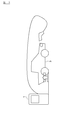
- FIG. 2 is a schematic diagram showing the states of the power feeding device 1 and the vehicle 3 when there is a request to use the other power feeding method during charging of the battery 33 by one power feeding method.
- the vehicle 3 ⁇ / b> A stops at the parking lot of the power feeding device 1, the power receiving coil 31 is in a position facing the power transmitting coil 11, and the vehicle 3 ⁇ / b> A battery is being charged by the non-contact power feeding method
- the vehicle 3B which is another vehicle, stops near the same power supply device 1, and the charging port 36 of the vehicle 3B and the power supply device 1 are connected by the charging cable 15, so that the power supply device 1 is supplied from the vehicle 3B.
- the output from the power supply device 1 has an upper limit depending on the rating of the AC power supply 2 connected to the power supply device 1 or the rating of the harness that constitutes the charging circuit in the power supply device 1.
- the vehicle 3 that is different from the vehicle 3 being charged is When there is a power supply request, power supply by the one power supply method is continued, and power supply by the other power supply method is waited.
- specific control will be described.
- the controller 10 stops the pulse communication of the communication device 18 when charging the battery 33 by the non-contact power feeding method which is the first power feeding method. The stop of the pulse communication is continued until the charging of the battery 33 by the non-contact power feeding method is completed.
- the controller 30 of the other vehicle 3 does not detect the pulse from the communication device 18 and may start charging by the power feeding method. Can not. Further, when the controller 10 detects the connection of the charging connector 14 to the charging port 36 while the pulse communication of the communication device 18 is stopped, the display unit 20 indicates that power supply by the contact power supply method is waiting. To display. When the charging of the battery 33 by the non-contact power feeding method is completed, the controller 10 restores the pulse communication of the communication device 18 so that the battery 3 of the other vehicle 3 can be charged by the contact power feeding method. .
- the controller 10 performs control so that charging of the battery 33 of the non-contact power feeding method which is the first power feeding method is continued and power feeding by the contact power feeding method which is the other power feeding method is waited.
- the controller 10 transmits a signal indicating a standby state of non-contact power feeding to the vehicle side by wireless communication as a response signal to the request signal from the vehicle 3. Furthermore, the controller 10 displays the standby state of non-contact power feeding on the display unit 20. On the other hand, when the controller 30 of the other vehicle receives a signal indicating the standby state of the non-contact power supply from the power supply device 1, the controller 30 displays the standby state of the non-contact power supply on the display unit 38.
- the controller 10 on the power feeding device side stops charging the battery 33 by the contact power feeding method
- the charging by the non-contact power feeding method can be accepted for the other vehicle 3 while stopping the pulse communication by the communication device 18.
- a signal to that effect is transmitted wirelessly.
- the controller 10 displays on the display unit 20 that power can be supplied by the non-contact power supply method.
- the controller 10 controls the power unit 12 to start power feeding by the non-contact power feeding method. Further, after receiving the acceptable signal, the vehicle-side controller 30 controls the power receiving circuit unit 32 to start charging the battery 33 by the non-contact power feeding method.
- the controller 10 performs control so as to continue charging the battery 33 of the contact power feeding method that is the first power feeding method and to wait for the power feeding by the non-contact power feeding method that is the other power feeding method.
- FIG. 3 is a schematic diagram showing the states of the power feeding device 1 and the vehicle 3 when a request for using the other power feeding method is made in the same vehicle while the battery 33 is charged by the one power feeding method.
- the vehicle 3 stops at the parking lot of the power feeding device 1, the power receiving coil 31 is in a position facing the power transmitting coil 11, and the battery of the vehicle 3 is being charged by the non-contact power feeding method.
- the charging port 36 of the same vehicle 3 and the power feeding device 1 are connected by the charging cable 15, whereby the vehicle 3 requests the power feeding device 1 to feed power by the contact power feeding method.
- the power supply efficiency in the non-contact power supply method is lower than the power supply efficiency in the contact power supply method. Therefore, although the user of the vehicle 3 has charged the battery 33 by, for example, the non-contact power feeding method, the charging connector 14 may be connected to the charging port 36 in order to accelerate the charging of the battery 33.
- the controller 30 on the vehicle side detects that the charging connector 14 is connected to the charging port 36 by the connection detection device 37 during charging of the battery 33 by the non-contact power feeding method
- the controller 30 on the vehicle side A request signal for stopping the power supply by the contact power supply method is wirelessly transmitted.
- the controller 30 controls the power receiving circuit unit 32 to stop power supply to the battery 33.
- the controller 10 on the power feeding device side stops the pulse communication of the communication device 18 during charging of the battery 33 by the non-contact power feeding method.
- the pulse communication is restored while stopping the power supply by the power supply method.
- the controller 30 enters a sleep state after transmitting a stop request signal.
- the controller 30 detects the output from the communication device 18 via the charging cable 15 to detect that contact power supply is possible, and returns from the sleep state. Controller 30 then controls converter 35 to start charging battery 33.
- the controller 30 detects that the charging connector 14 is connected to the charging port 36 during charging of the battery 33 by the contact power feeding method, the request signal for stopping the power feeding by the non-contact power feeding method. And the battery 33 is charged with the electric power input from the charging port 36.
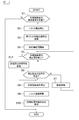
- FIG. 4 is a flowchart illustrating a control procedure of the controller 10 on the power supply apparatus side when power supply by non-contact power supply is started from a state where power is not supplied by the two-system power supply method.
- the controller 10 on the power feeding apparatus side determines whether or not a request signal for power feeding by the non-contact power feeding method is received from the vehicle 3 in step S ⁇ b> 1. If the power supply request signal by the non-contact power supply method has not been received, the control of this example is terminated.
- the controller 10 When receiving the power supply request signal by the non-contact power supply method, the controller 10 stops the pulse communication of the communication device 18 (step S2). In step S ⁇ b> 3, the controller 10 transmits a signal indicating that charging by the non-contact power feeding method is acceptable to the vehicle 3.
- step S4 the controller 10 controls the power unit 12 to start power feeding by the non-contact power feeding method.
- step S ⁇ b> 5 the controller 10 determines whether or not there is a power feeding stop operation by the non-contact power feeding method by a user operation on the power feeding device 1. If there is no stop operation, in step S6, the controller 10 determines whether or not a non-contact power supply stop request signal has been received from the vehicle 3. If the stop request signal has not been received, in step S7, the controller 10 determines the power unit based on the required power from the vehicle 3 received by the wireless communication unit 19 or information indicating the state of the battery 33. 12 is controlled to supply power by a non-contact power supply method. Then, after the control process of step 7, the process returns to step S5.
- step S6 the controller 10 stops power supply by the non-contact power supply method in step S8.
- step S9 the controller 10 resumes the pulse communication of the communication device 18.
- step S10 the controller 10 displays on the display unit 20 that power can be supplied by the contact power supply method, and ends the control of this example.
- step S11 the controller 10 transmits a power supply stop signal to the vehicle 3, and the process proceeds to step S8.
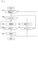
- FIG. 5 is a flowchart illustrating a control procedure of the controller 10 on the power supply apparatus side when power supply by contact power supply is started from a state where power is not supplied by the two-system power supply method.
- step S21 the controller 10 detects the connection of the charging connector 14 to the charging port 36 and starts contact power feeding.
- step S22 the controller 10 determines whether or not there is a request for power supply by the non-contact power supply method. If there is a request for power supply, the controller 10 transmits a signal indicating a non-contact power supply standby state to the vehicle 3 in step S23.
- step S ⁇ b> the controller 10 displays a non-contact power supply standby state on the display unit 20.
- step S ⁇ b> 25 the controller 10 continues the power supply control by maintaining the relay switch 16 in the on state.
- step S26 the controller 10 determines whether or not to stop power feeding.
- step S27 the controller 10 transmits a signal indicating that charging by the contact power feeding method is acceptable while turning off the relay switch 16. And in step S28, the controller 10 stops the pulse communication of the communication apparatus 18 in preparation for the electric power feeding by a non-contact electric power feeding system. In step S29, the controller 10 displays on the display unit 20 that power can be supplied by the non-contact power supply method, and ends the control of the contact power supply method of this example.
- step S30 the controller 10 performs power supply control by the contact power supply method, similarly to the control of step S25.
- step S31 the controller 10 determines whether or not to stop power feeding, similarly to step S26.
- step S ⁇ b> 32 the controller 10 turns off the relay switch 16 and ends the power supply by the contact power supply method.
- step S22 when the control of the contact power supply method of this example is finished in a state where there is a request for power supply by the noncontact power supply method, the process proceeds to the control flow of step S4 shown in FIG. Power supply control of the power supply method is executed.
- FIG. 6 is a flowchart showing a control procedure of the controller 30 on the vehicle side when power supply by non-contact power supply is started from a state where power is not supplied by the two-system power supply method.
- step S41 the vehicle-side controller 30 transmits a power supply request signal by the non-contact power supply method to the power supply apparatus 1 (the request signal is received in step S1 of FIG. 4 or step S22 of FIG. 5). ).
- step S42 the controller 30 determines whether or not a standby state signal has been received (the standby state signal is transmitted in step S23 of FIG. 5).
- step S43 the controller 30 displays the non-contact power supply standby state on the display unit 38, and proceeds to step S44. If the controller 30 has not received a standby signal in step S32, the process proceeds to step S44.
- step S44 the controller 30 determines whether or not a signal indicating that charging by the contact power feeding method is acceptable is received (the acceptable signal is transmitted in step S27 in FIG. 5). If an acceptable signal is received, in step S45, the controller 30 controls the power receiving circuit unit 32 to start charging by non-contact power feeding. In step 46, the controller 30 determines whether or not the connection detection device 37 has connected to the charging port 36 of the charging connector 14.
- step S47 the controller 30 determines whether or not a power supply stop signal has been received from the power supply apparatus 1 (the power supply stop signal is shown in FIG. 4). In step S11). When the power supply stop signal has not been received, the controller 30 continues the charging by the non-contact power supply while managing the state of the battery with the sensor 34 (step S48). In step S49, controller 30 determines whether or not the SOC of battery 33 has reached the target SOC. If the SOC of the battery 33 has not reached the target SOC, the process returns to step S46.
- step S50 the controller 30 transmits a power supply stop request signal to the power supply apparatus 1 (the stop request signal is transmitted in step S6 of FIG. 1). Received).
- step 51 the controller 30 ends the charging by the non-contact power feeding and ends the control of this example.
- step S46 if the charging connector 14 is connected to the charging port 36, the controller 30 terminates the charging by the non-contact power feeding and switches to the charging by the contact power feeding.
- a stop request signal is transmitted (the stop request signal is received in step S6 in FIG. 1).
- step S53 the controller 30 performs charging control by contact power feeding.
- the detailed flow of charge control by contact power supply corresponds to steps S61 to S67 of FIG. 7 described later.
- step S54 determines in step S54 whether or not a predetermined time has elapsed.
- the predetermined time corresponds to a non-contact power supply waiting time when charging by the power supply method is not performed. That is, until the predetermined time elapses, the standby state in step S43 is continued unless the power supply apparatus 1 enters a state of accepting non-contact power supply.
- step S55 the controller 30 displays on the display unit 38 that charging by the non-contact power feeding method is impossible, and ends the control of this example. To do.
- FIG. 7 is a flowchart illustrating a control procedure of the controller 30 on the vehicle side when power supply by contact power supply is started from a state where power is not supplied by the two-system power supply method.
- step S ⁇ b> 61 the controller 30 determines whether or not the connection detection device 37 has connected to the charging port 36 of the charging connector 14. If the charging connector 14 is connected to the charging port 36, the controller 30 determines whether or not a pulse from the communication device 18 is detected in step S62. When the pulse is detected, the controller 30 charges the battery 33 by controlling the converter 35 in accordance with the state of the battery 33 in step S63. In step S64, controller 30 determines whether or not the SOC of battery 33 has reached the target SOC. If the SOC of the battery 33 has not reached the target SOC, the process returns to step S63.
- step S65 the controller 30 stops the operation of the converter 35 and ends the charging of the battery 33 by the contact power feeding method.
- step S67 the controller 30 determines whether or not a predetermined time has elapsed. If the predetermined time has not elapsed, the process returns to step S62. On the other hand, if the predetermined time has not elapsed, the control of this example is terminated.
- the controller 30 determines whether or not charging by the contact power supply method is possible by pulse communication of the communication device 18, but pulse communication is also performed when the power supply device 1 is not connected to the AC power supply 2. Stopped. Therefore, when the time-out time is set in step S67 of FIG. 7 and the pulse communication returns within the set time, charging by the contact power feeding method is performed, and when the pulse communication does not return within the set time. For example, the controller 30 terminates the control while notifying the display unit 38 of an error message indicating that contact charging cannot be performed.
- the power supply from the other vehicle is performed while the battery of the vehicle is charged by either one of the contactless power supply method using the contactless power supply unit and the contact power supply method using the contact power supply unit.
- power supply by one power supply method is continued, and power supply by the other power supply method is put on standby.
- power supply with one power supply method is performed. Until the power supply is completed, power supply by the other power supply method does not start. Therefore, according to the request from the other vehicle, it is possible to control so as not to interrupt the charging of the battery of the vehicle that has been previously fed.
- the charging connector 14 when it is detected that the charging connector 14 is connected to the charging port 36 during charging of the battery 33 by the non-contact power feeding method, a signal for stopping the power feeding by the non-contact power feeding method is provided. And the battery is charged with the electric power input from the charging port 36.
- the contact power supply method can be prioritized. Thereby, the charging efficiency of the battery 33 can be improved.
- the power unit 12 corresponds to the “non-contact power feeding unit” of the present invention
- the charging circuit for the contact power feeding system including the relay switch 16 is the “contact power feeding unit” of the present invention
- the wireless communication unit 39 is the “ The charging port 36 corresponds to the “connecting terminal” of the present invention.
Landscapes
- Engineering & Computer Science (AREA)
- Power Engineering (AREA)
- Transportation (AREA)
- Mechanical Engineering (AREA)
- Computer Networks & Wireless Communication (AREA)
- Charge And Discharge Circuits For Batteries Or The Like (AREA)
- Electric Propulsion And Braking For Vehicles (AREA)
- Current-Collector Devices For Electrically Propelled Vehicles (AREA)
Abstract
Description
2…交流電源
3…車両
10、30…コントローラ
11…送電コイル
12…パワーユニット
13、17…電流センサ
14…充電コネクタ
15…充電ケーブル
16…リレースイッチ
18…通信装置
19、39…無線通信部
20、38…表示部
21、40…メモリ
31…受電コイル
32…受電回路部
33…バッテリ
34…センサ
35…コンバータ
36…充電ポート
37…接続検出装置
38…表示部
Claims (4)
- 少なくとも磁気的な結合により非接触で、送電コイルから受電コイルに電力を供給して、車両のバッテリを充電する非接触給電部と
車両に設けられた接続端子にケーブルを介して電気的に接続され、前記車両のバッテリに電力を供給する接触給電部と、
前記非接触給電部及び前記接触給電部を制御するコントローラとを備え、
前記コントローラは、
前記非接触給電部による非接触給電方式と前記接触給電部による接触給電方式のうち、いずれか一方の給電方式による第1車両のバッテリの充電中に、第2車両から他方の給電方式による給電の要求があった場合には、前記一方の給電方式による給電を継続させて、前記他方の給電方式による給電を待機させる
ことを特徴とする給電装置。 - 請求項1記載の給電装置であって、
前記コントローラは、
前記一方の給電方式による前記第1車両のバッテリの充電中に、前記他方の給電方式による前記第2車両のバッテリへの給電の要求があった場合には、前記第2車両に対して給電の待機状態であることを通知する
ことを特徴とする給電装置。 - 請求項1又は2に記載の給電装置と、前記受電コイルを有する車両とを備えた、非接触給電システムにおいて、
前記車両は、
前記給電装置に対して給電を要求する要求信号を無線通信で送信する通信手段と、
前記給電装置とケーブルを介して電気的に接続可能な接続端子と、
前記受電コイルの電力、及び前記ケーブルを介して前記接続端子から入力される電力により充電されるバッテリと、
前記通信手段を制御する車両側コントローラとを備え、
前記車両側コントローラは、
前記受電コイルからの電力に基づく非接触給電方式による前記バッテリの充電中に、前記ケーブルのコネクタが前記接続端子に接続されたことを検出した場合には、前記非接触給電方式による給電を停止させる信号を送信し、前記接続端子から入力される電力でバッテリを充電する
ことを特徴とする非接触給電システム。 - 少なくとも磁気的結合により、給電装置に設けられた送電コイルとの間で、非接触で電力を受電する受電コイルと、
前記給電装置に対して給電を要求する要求信号を無線通信で送信する通信手段と、
前記給電装置とケーブルを介して電気的に接続可能な接続端子と、
前記受電コイルの電力、及び前記ケーブルを介して前記接続端子から入力される電力により充電されるバッテリと、
前記通信手段を制御する車両側コントローラとを備え、
前記車両側コントローラは、
前記受電コイルからの電力に基づく非接触給電方式による前記バッテリの充電中に、前記ケーブルのコネクタが前記接続端子に接続されたことを検出した場合には、前記非接触給電方式による給電を停止させる信号を送信し、前記接続端子から入力される電力でバッテリを充電する
ことを特徴とする車両。
Priority Applications (9)
| Application Number | Priority Date | Filing Date | Title |
|---|---|---|---|
| US14/778,499 US9878628B2 (en) | 2013-03-29 | 2014-03-24 | Power supply device, vehicle and non-contact power supply system |
| BR112015025038-6A BR112015025038B1 (pt) | 2013-03-29 | 2014-03-24 | Dispositivo de fornecimento de energia e sistema de fornecimento de energia sem contato |
| EP14776452.6A EP2983267B1 (en) | 2013-03-29 | 2014-03-24 | Electricity supply device, vehicle, and contactless electricity supply system |
| RU2015146515A RU2614052C1 (ru) | 2013-03-29 | 2014-03-24 | Устройство подачи электрической энергии, транспортное средство и система бесконтактной подачи электрической энергии |
| JP2015508491A JP5979310B2 (ja) | 2013-03-29 | 2014-03-24 | 給電装置、車両及び非接触給電システム |
| CA2908349A CA2908349C (en) | 2013-03-29 | 2014-03-24 | Power supply device, vehicle, and non-contact power supply system |
| CN201480016824.6A CN105052003A (zh) | 2013-03-29 | 2014-03-24 | 供电装置、车辆及非接触式供电系统 |
| MX2015013707A MX347220B (es) | 2013-03-29 | 2014-03-24 | Dispositivo de suministro de energía, vehículo y sistema de suministro de energía sin contacto. |
| KR1020157025273A KR20150119323A (ko) | 2013-03-29 | 2014-03-24 | 급전 장치, 차량 및 비접촉 급전 시스템 |
Applications Claiming Priority (2)
| Application Number | Priority Date | Filing Date | Title |
|---|---|---|---|
| JP2013-072256 | 2013-03-29 | ||
| JP2013072256 | 2013-03-29 |
Publications (1)
| Publication Number | Publication Date |
|---|---|
| WO2014157095A1 true WO2014157095A1 (ja) | 2014-10-02 |
Family
ID=51624068
Family Applications (1)
| Application Number | Title | Priority Date | Filing Date |
|---|---|---|---|
| PCT/JP2014/058095 Ceased WO2014157095A1 (ja) | 2013-03-29 | 2014-03-24 | 給電装置、車両及び非接触給電システム |
Country Status (11)
| Country | Link |
|---|---|
| US (1) | US9878628B2 (ja) |
| EP (1) | EP2983267B1 (ja) |
| JP (1) | JP5979310B2 (ja) |
| KR (1) | KR20150119323A (ja) |
| CN (1) | CN105052003A (ja) |
| BR (1) | BR112015025038B1 (ja) |
| CA (1) | CA2908349C (ja) |
| MX (1) | MX347220B (ja) |
| MY (1) | MY162019A (ja) |
| RU (1) | RU2614052C1 (ja) |
| WO (1) | WO2014157095A1 (ja) |
Cited By (5)
| Publication number | Priority date | Publication date | Assignee | Title |
|---|---|---|---|---|
| JP2018121478A (ja) * | 2017-01-26 | 2018-08-02 | 電気興業株式会社 | 車両用無線充電システム および 車両用有線無線両用充電システム |
| JP2019531680A (ja) * | 2016-08-12 | 2019-10-31 | グリーン パワー カンパニー, リミテッドGreen Power Co., Ltd. | 電気自動車用有線無線兼用充電装置 |
| WO2021149937A1 (ko) * | 2020-01-20 | 2021-07-29 | 엘지전자 주식회사 | 무선전력 수신장치, 무선전력 수신방법 및 무선 충전 서비스 제공 방법 |
| US11358122B2 (en) | 2019-04-10 | 2022-06-14 | Desikhan Co., Ltd. | Moisture absorbent pack for vehicle lamp |
| JP2023105548A (ja) * | 2022-01-19 | 2023-07-31 | トヨタ自動車株式会社 | 送電装置の制御装置 |
Families Citing this family (34)
| Publication number | Priority date | Publication date | Assignee | Title |
|---|---|---|---|---|
| US12083933B2 (en) * | 2007-05-10 | 2024-09-10 | Auckland Uniservices Limited | Systems and methods for battery charging |
| JP6207152B2 (ja) * | 2012-12-27 | 2017-10-04 | キヤノン株式会社 | 給電装置、制御方法及びコンピュータプログラム |
| EP2983267B1 (en) * | 2013-03-29 | 2018-11-28 | Nissan Motor Co., Ltd | Electricity supply device, vehicle, and contactless electricity supply system |
| US10336296B2 (en) * | 2015-04-07 | 2019-07-02 | Nissan Motor Co., Ltd. | Locking/unlocking system |
| CN105667327B (zh) * | 2015-12-30 | 2018-08-28 | 上海国际汽车城(集团)有限公司 | 基于自动机械臂的电动汽车自动充电方法 |
| WO2018039474A1 (en) | 2016-08-24 | 2018-03-01 | Keyssa Systems, Inc. | Mechanical connectors for contactless communication units |
| CN106374629B (zh) * | 2016-09-28 | 2019-03-05 | 中车唐山机车车辆有限公司 | 电磁感应电能传输系统 |
| JP6421807B2 (ja) * | 2016-10-03 | 2018-11-14 | トヨタ自動車株式会社 | 車両 |
| JP6756381B2 (ja) * | 2017-01-30 | 2020-09-16 | 日産自動車株式会社 | 駐車支援方法及び駐車支援装置 |
| JP6772872B2 (ja) * | 2017-02-06 | 2020-10-21 | トヨタ自動車株式会社 | 車両 |
| DE102017218165A1 (de) | 2017-10-11 | 2019-04-11 | Audi Ag | Energiebereitstellungseinrichtung zum Bereitstellen elektrischer Energie für ein Kraftfahrzeug sowie Verfahren zum Betreiben einer Energiebereitstellungseinrichtung |
| US20220134892A1 (en) * | 2017-10-11 | 2022-05-05 | Audi Ag | Energy provision device |
| DE102018007911A1 (de) * | 2017-10-18 | 2019-04-18 | Sew-Eurodrive Gmbh & Co Kg | Ladegerät und System zur Energieübertragung an ein Mobilteil mit Energiespeicher und Sekundärwicklung |
| CN107947379B (zh) * | 2017-12-20 | 2023-08-01 | 温州正泰船岸电气有限公司 | 无线连接的船舶岸电系统 |
| DE102018203371A1 (de) * | 2018-03-07 | 2019-09-12 | Audi Ag | Kontaktlose Ladeeinrichtung, Ladesystem und Verfahren zum kontaktlosen Laden eines Energiespeichers eines Kraftfahrzeugs |
| JP7200599B2 (ja) * | 2018-10-23 | 2023-01-10 | トヨタ自動車株式会社 | 車両 |
| CN111342071B (zh) * | 2018-12-18 | 2021-12-21 | 东莞新能德科技有限公司 | 电池组件、电子设备及电池检测系统 |
| JP7110129B2 (ja) * | 2019-01-22 | 2022-08-01 | 株式会社マキタ | 電源制御装置、電力供給装置および電動作業システム |
| CN109808540B (zh) * | 2019-02-27 | 2021-07-23 | 恒大恒驰新能源汽车研究院(上海)有限公司 | 一种充电方法、计算机设备、存储介质以及系统 |
| CN110001445B (zh) * | 2019-05-28 | 2024-02-09 | 北京有感科技有限责任公司 | 车辆充电方法及设备 |
| US10861301B1 (en) * | 2019-06-24 | 2020-12-08 | Zealio Electronics Co., Ltd. | Multifunctional smart holder and control method thereof |
| US11571983B2 (en) | 2020-03-17 | 2023-02-07 | Toyota Motor North America, Inc. | Distance-based energy transfer from a transport |
| US11618329B2 (en) | 2020-03-17 | 2023-04-04 | Toyota Motor North America, Inc. | Executing an energy transfer directive for an idle transport |
| US11890952B2 (en) | 2020-03-17 | 2024-02-06 | Toyot Motor North America, Inc. | Mobile transport for extracting and depositing energy |
| US11552507B2 (en) * | 2020-03-17 | 2023-01-10 | Toyota Motor North America, Inc. | Wirelessly notifying a transport to provide a portion of energy |
| US11685283B2 (en) | 2020-03-17 | 2023-06-27 | Toyota Motor North America, Inc. | Transport-based energy allocation |
| US11458849B2 (en) * | 2020-03-23 | 2022-10-04 | Ford Global Technologies, Llc | Charging input selector systems for electrified vehicles |
| CN111479175B (zh) * | 2020-04-17 | 2020-12-22 | 中国科学院地质与地球物理研究所 | 一种非接触连接器、信号处理方法及存储介质 |
| US12588901B2 (en) | 2020-06-11 | 2026-03-31 | Kohler Co. | Health care mirror |
| US12042043B2 (en) | 2020-06-11 | 2024-07-23 | Kohler Co. | Temperature tracking mirror |
| US11801773B1 (en) * | 2022-08-18 | 2023-10-31 | Beta Air, Llc | Methods and systems for ground-based thermal conditioning for an electric aircraft |
| US20230275444A1 (en) * | 2022-02-25 | 2023-08-31 | Milwaukee Electric Tool Corporation | Magnet coupling assembly |
| US11993397B1 (en) * | 2023-03-10 | 2024-05-28 | Beta Air, Llc | System and a method for preconditioning a power source of an electric aircraft |
| DE102023213082A1 (de) * | 2023-12-20 | 2025-06-26 | Siemens Aktiengesellschaft | Vorrichtung für das induktive oder kabelgebundene Laden eines Elektrofahrzeugs |
Citations (5)
| Publication number | Priority date | Publication date | Assignee | Title |
|---|---|---|---|---|
| WO1998032209A1 (en) * | 1997-01-22 | 1998-07-23 | Schott Power Systems Incorporated | Method and apparatus for charging a plurality of electric vehicles |
| WO1999019959A1 (en) * | 1997-10-10 | 1999-04-22 | Schott Power Systems Incorporated | Method and apparatus for charging one or more electric vehicles |
| WO2010131349A1 (ja) | 2009-05-14 | 2010-11-18 | トヨタ自動車株式会社 | 車両用充電装置 |
| JP2012023825A (ja) * | 2010-07-13 | 2012-02-02 | Toshiba Corp | 充電装置 |
| JP2013179723A (ja) * | 2012-02-10 | 2013-09-09 | Sumitomo Electric Ind Ltd | 充電装置及び充電方法 |
Family Cites Families (12)
| Publication number | Priority date | Publication date | Assignee | Title |
|---|---|---|---|---|
| JPH11252810A (ja) * | 1998-03-03 | 1999-09-17 | Toyota Autom Loom Works Ltd | バッテリ車の車載側充電装置 |
| JP2003153456A (ja) | 2001-11-08 | 2003-05-23 | Olympus Optical Co Ltd | 充電装置、及び電子カメラ |
| JP4254894B1 (ja) * | 2007-11-29 | 2009-04-15 | トヨタ自動車株式会社 | 充電システムおよびその作動方法 |
| JP5062229B2 (ja) * | 2009-08-05 | 2012-10-31 | 株式会社デンソー | 給電コントローラおよび給電システム |
| US8698451B2 (en) * | 2009-12-18 | 2014-04-15 | General Electric Company | Apparatus and method for rapid charging using shared power electronics |
| KR20100035152A (ko) | 2010-03-15 | 2010-04-02 | 신이균 | 전기자동차 배터리 충전장치 |
| WO2012042902A1 (ja) | 2010-10-01 | 2012-04-05 | パナソニック株式会社 | 電気自動車の電力供給システム、このシステムに用いる電気自動車および給電装置 |
| JP5387552B2 (ja) * | 2010-12-16 | 2014-01-15 | 株式会社デンソー | 車両用電源装置 |
| DE102011056516B4 (de) * | 2010-12-16 | 2022-10-13 | Denso Corporation | Leistungsversorgungsvorrichtung für Fahrzeuge |
| DE102010055925A1 (de) * | 2010-12-23 | 2012-06-28 | Daimler Ag | Kraftfahrzeugvorrichtung |
| US9533591B2 (en) * | 2012-01-30 | 2017-01-03 | Toyota Jidosha Kabushiki Kaisha | Vehicular power reception device, power supply apparatus, and electric power transfer system |
| EP2983267B1 (en) * | 2013-03-29 | 2018-11-28 | Nissan Motor Co., Ltd | Electricity supply device, vehicle, and contactless electricity supply system |
-
2014
- 2014-03-24 EP EP14776452.6A patent/EP2983267B1/en active Active
- 2014-03-24 BR BR112015025038-6A patent/BR112015025038B1/pt not_active IP Right Cessation
- 2014-03-24 CA CA2908349A patent/CA2908349C/en active Active
- 2014-03-24 MX MX2015013707A patent/MX347220B/es active IP Right Grant
- 2014-03-24 RU RU2015146515A patent/RU2614052C1/ru active
- 2014-03-24 JP JP2015508491A patent/JP5979310B2/ja active Active
- 2014-03-24 US US14/778,499 patent/US9878628B2/en active Active
- 2014-03-24 WO PCT/JP2014/058095 patent/WO2014157095A1/ja not_active Ceased
- 2014-03-24 KR KR1020157025273A patent/KR20150119323A/ko not_active Ceased
- 2014-03-24 MY MYPI2015703357A patent/MY162019A/en unknown
- 2014-03-24 CN CN201480016824.6A patent/CN105052003A/zh active Pending
Patent Citations (5)
| Publication number | Priority date | Publication date | Assignee | Title |
|---|---|---|---|---|
| WO1998032209A1 (en) * | 1997-01-22 | 1998-07-23 | Schott Power Systems Incorporated | Method and apparatus for charging a plurality of electric vehicles |
| WO1999019959A1 (en) * | 1997-10-10 | 1999-04-22 | Schott Power Systems Incorporated | Method and apparatus for charging one or more electric vehicles |
| WO2010131349A1 (ja) | 2009-05-14 | 2010-11-18 | トヨタ自動車株式会社 | 車両用充電装置 |
| JP2012023825A (ja) * | 2010-07-13 | 2012-02-02 | Toshiba Corp | 充電装置 |
| JP2013179723A (ja) * | 2012-02-10 | 2013-09-09 | Sumitomo Electric Ind Ltd | 充電装置及び充電方法 |
Non-Patent Citations (1)
| Title |
|---|
| See also references of EP2983267A4 |
Cited By (7)
| Publication number | Priority date | Publication date | Assignee | Title |
|---|---|---|---|---|
| JP2019531680A (ja) * | 2016-08-12 | 2019-10-31 | グリーン パワー カンパニー, リミテッドGreen Power Co., Ltd. | 電気自動車用有線無線兼用充電装置 |
| US10946753B2 (en) | 2016-08-12 | 2021-03-16 | Green Power Co., Ltd. | Wired and wireless charging device for electric vehicle |
| JP2018121478A (ja) * | 2017-01-26 | 2018-08-02 | 電気興業株式会社 | 車両用無線充電システム および 車両用有線無線両用充電システム |
| US11358122B2 (en) | 2019-04-10 | 2022-06-14 | Desikhan Co., Ltd. | Moisture absorbent pack for vehicle lamp |
| WO2021149937A1 (ko) * | 2020-01-20 | 2021-07-29 | 엘지전자 주식회사 | 무선전력 수신장치, 무선전력 수신방법 및 무선 충전 서비스 제공 방법 |
| JP2023105548A (ja) * | 2022-01-19 | 2023-07-31 | トヨタ自動車株式会社 | 送電装置の制御装置 |
| JP7616102B2 (ja) | 2022-01-19 | 2025-01-17 | トヨタ自動車株式会社 | 送電装置の制御装置 |
Also Published As
| Publication number | Publication date |
|---|---|
| EP2983267A4 (en) | 2016-06-22 |
| RU2614052C1 (ru) | 2017-03-22 |
| BR112015025038B1 (pt) | 2021-12-28 |
| CA2908349A1 (en) | 2014-10-02 |
| EP2983267A1 (en) | 2016-02-10 |
| US20160288653A1 (en) | 2016-10-06 |
| MX347220B (es) | 2017-04-20 |
| US9878628B2 (en) | 2018-01-30 |
| BR112015025038A2 (pt) | 2021-08-17 |
| MX2015013707A (es) | 2016-02-26 |
| JPWO2014157095A1 (ja) | 2017-02-16 |
| CA2908349C (en) | 2016-09-20 |
| MY162019A (en) | 2017-05-31 |
| CN105052003A (zh) | 2015-11-11 |
| EP2983267B1 (en) | 2018-11-28 |
| KR20150119323A (ko) | 2015-10-23 |
| JP5979310B2 (ja) | 2016-08-24 |
Similar Documents
| Publication | Publication Date | Title |
|---|---|---|
| JP5979310B2 (ja) | 給電装置、車両及び非接触給電システム | |
| JP5810632B2 (ja) | 非接触給電装置 | |
| KR101676591B1 (ko) | 비접촉 급전 시스템 | |
| US10052963B2 (en) | Contactless power transfer system and method of controlling the same | |
| US10173538B2 (en) | Wireless charging system and wireless charging transmission apparatus and method changing frequency to transmit power | |
| JP6090333B2 (ja) | 非接触給電装置、非接触給電システム及び非接触給電方法 | |
| KR101299109B1 (ko) | 전기 자동차용 충전기의 제어 시스템 및 그 방법 | |
| US10086712B2 (en) | Charging apparatus and non-contact power feeding apparatus | |
| US20190118664A1 (en) | Non-contact electric power transmission system, charging station, and vehicle | |
| JP2015100230A (ja) | 非接触送受電システム | |
| JP5605301B2 (ja) | 非接触給電システム | |
| JP2014197939A (ja) | 給電装置 | |
| JP2016063600A (ja) | 受電装置 | |
| JP2021158916A (ja) | 非接触充電システム、並びに送電装置及び方法 | |
| JP2023173385A (ja) | 充電装置 | |
| JP2013258872A (ja) | 伝送装置及び非接触電力伝送システム |
Legal Events
| Date | Code | Title | Description |
|---|---|---|---|
| WWE | Wipo information: entry into national phase |
Ref document number: 201480016824.6 Country of ref document: CN |
|
| 121 | Ep: the epo has been informed by wipo that ep was designated in this application |
Ref document number: 14776452 Country of ref document: EP Kind code of ref document: A1 |
|
| ENP | Entry into the national phase |
Ref document number: 2015508491 Country of ref document: JP Kind code of ref document: A |
|
| ENP | Entry into the national phase |
Ref document number: 20157025273 Country of ref document: KR Kind code of ref document: A |
|
| WWE | Wipo information: entry into national phase |
Ref document number: 14778499 Country of ref document: US |
|
| WWE | Wipo information: entry into national phase |
Ref document number: MX/A/2015/013707 Country of ref document: MX |
|
| ENP | Entry into the national phase |
Ref document number: 2908349 Country of ref document: CA |
|
| NENP | Non-entry into the national phase |
Ref country code: DE |
|
| WWE | Wipo information: entry into national phase |
Ref document number: IDP00201506506 Country of ref document: ID |
|
| WWE | Wipo information: entry into national phase |
Ref document number: 2014776452 Country of ref document: EP |
|
| ENP | Entry into the national phase |
Ref document number: 2015146515 Country of ref document: RU Kind code of ref document: A |
|
| REG | Reference to national code |
Ref country code: BR Ref legal event code: B01A Ref document number: 112015025038 Country of ref document: BR |
|
| ENP | Entry into the national phase |
Ref document number: 112015025038 Country of ref document: BR Kind code of ref document: A2 Effective date: 20150929 |
|
| ENPC | Correction to former announcement of entry into national phase, pct application did not enter into the national phase |
Ref document number: 112015025038 Country of ref document: BR Kind code of ref document: A2 Free format text: ANULADA A PUBLICACAO CODIGO 1.3 NA RPI NO 2428 DE 18/07/2017 POR TER SIDO INDEVIDA. |
|
| REG | Reference to national code |
Ref country code: BR Ref legal event code: B01E Ref document number: 112015025038 Country of ref document: BR Kind code of ref document: A2 Free format text: APRESENTAR A TRADUCAO SIMPLES DA FOLHA DE ROSTO DA CERTIDAO DE DEPOSITO DA PRIORIDADE JP 2013-072256 DE 29/03/2013 OU DECLARACAO CONTENDO, OBRIGATORIAMENTE, TODOS OS DADOS IDENTIFICADORES DESTA (DEPOSITANTE(S), INVENTOR(ES), NUMERO DE REGISTRO, DATA DE DEPOSITO E TITULO), CONFORME O PARAGRAFO UNICO DO ART. 25 DA RESOLUCAO 77/2013, UMA VEZ QUE NAO FOI POSSIVEL DETERMINAR O(S) TITULAR(ES) DA CITADA PRIORIDADE, NEM SEUS INVENTORES, INFORMACAO NECESSARIA PARA O EXAME. |
|
| ENP | Entry into the national phase |
Ref document number: 112015025038 Country of ref document: BR Kind code of ref document: A2 Effective date: 20150929 |