WO2014157113A1 - 軸受部材、端部部材、感光体ドラムユニット、及びプロセスカートリッジ - Google Patents
軸受部材、端部部材、感光体ドラムユニット、及びプロセスカートリッジ Download PDFInfo
- Publication number
- WO2014157113A1 WO2014157113A1 PCT/JP2014/058133 JP2014058133W WO2014157113A1 WO 2014157113 A1 WO2014157113 A1 WO 2014157113A1 JP 2014058133 W JP2014058133 W JP 2014058133W WO 2014157113 A1 WO2014157113 A1 WO 2014157113A1
- Authority
- WO
- WIPO (PCT)
- Prior art keywords
- shaft
- shaft member
- rotational force
- bearing member
- groove
- Prior art date
- Legal status (The legal status is an assumption and is not a legal conclusion. Google has not performed a legal analysis and makes no representation as to the accuracy of the status listed.)
- Ceased
Links
Images











Classifications
-
- G—PHYSICS
- G03—PHOTOGRAPHY; CINEMATOGRAPHY; ANALOGOUS TECHNIQUES USING WAVES OTHER THAN OPTICAL WAVES; ELECTROGRAPHY; HOLOGRAPHY
- G03G—ELECTROGRAPHY; ELECTROPHOTOGRAPHY; MAGNETOGRAPHY
- G03G15/00—Apparatus for electrographic processes using a charge pattern
- G03G15/75—Details relating to xerographic drum, band or plate, e.g. replacing, testing
- G03G15/751—Details relating to xerographic drum, band or plate, e.g. replacing, testing relating to drum
-
- G—PHYSICS
- G03—PHOTOGRAPHY; CINEMATOGRAPHY; ANALOGOUS TECHNIQUES USING WAVES OTHER THAN OPTICAL WAVES; ELECTROGRAPHY; HOLOGRAPHY
- G03G—ELECTROGRAPHY; ELECTROPHOTOGRAPHY; MAGNETOGRAPHY
- G03G15/00—Apparatus for electrographic processes using a charge pattern
- G03G15/75—Details relating to xerographic drum, band or plate, e.g. replacing, testing
- G03G15/757—Drive mechanisms for photosensitive medium, e.g. gears
-
- G—PHYSICS
- G03—PHOTOGRAPHY; CINEMATOGRAPHY; ANALOGOUS TECHNIQUES USING WAVES OTHER THAN OPTICAL WAVES; ELECTROGRAPHY; HOLOGRAPHY
- G03G—ELECTROGRAPHY; ELECTROPHOTOGRAPHY; MAGNETOGRAPHY
- G03G21/00—Arrangements not provided for by groups G03G13/00 - G03G19/00, e.g. cleaning, elimination of residual charge
- G03G21/16—Mechanical means for facilitating the maintenance of the apparatus, e.g. modular arrangements
- G03G21/1642—Mechanical means for facilitating the maintenance of the apparatus, e.g. modular arrangements for connecting the different parts of the apparatus
- G03G21/1647—Mechanical connection means
-
- G—PHYSICS
- G03—PHOTOGRAPHY; CINEMATOGRAPHY; ANALOGOUS TECHNIQUES USING WAVES OTHER THAN OPTICAL WAVES; ELECTROGRAPHY; HOLOGRAPHY
- G03G—ELECTROGRAPHY; ELECTROPHOTOGRAPHY; MAGNETOGRAPHY
- G03G21/00—Arrangements not provided for by groups G03G13/00 - G03G19/00, e.g. cleaning, elimination of residual charge
- G03G21/16—Mechanical means for facilitating the maintenance of the apparatus, e.g. modular arrangements
- G03G21/18—Mechanical means for facilitating the maintenance of the apparatus, e.g. modular arrangements using a processing cartridge, whereby the process cartridge comprises at least two image processing means in a single unit
- G03G21/1839—Means for handling the process cartridge in the apparatus body
- G03G21/1857—Means for handling the process cartridge in the apparatus body for transmitting mechanical drive power to the process cartridge, drive mechanisms, gears, couplings, braking mechanisms
- G03G21/186—Axial couplings
Definitions
- the present invention relates to a process cartridge that is detachably attached to an image forming apparatus such as a laser printer or a copying machine, a photosensitive drum unit provided in the process cartridge, an end member attached to the photosensitive drum of the photosensitive drum unit, and
- the present invention relates to a bearing member that constitutes an end member.
- Image forming apparatuses such as laser printers and copiers include a process cartridge that is detachable from a main body of the image forming apparatus (hereinafter sometimes referred to as “apparatus main body”).
- the process cartridge is a member that forms contents to be represented such as characters and figures, and transfers the contents to a recording medium such as paper.
- the process cartridge includes a photosensitive drum on which the contents to be transferred are formed. Therefore, various means for forming the content to be transferred to the photosensitive drum are also arranged in the process cartridge. Examples of these means include a developing means, a means for charging the photosensitive drum, and a means for cleaning the photosensitive drum.
- the same process cartridge is attached to or detached from the main body for maintenance, or the old process cartridge is detached from the main body to replace it with a new process cartridge, and the new process cartridge is attached to the main body.
- Such a process cartridge can be attached and detached by the user of the image forming apparatus by himself / herself.
- the photosensitive drum included in the process cartridge is engaged with the drive shaft of the apparatus main body directly or via another member so that the photosensitive drum is rotated by receiving rotational force from the drive shaft. It is configured. Therefore, in order to attach and detach the process cartridge to and from the apparatus main body, it is necessary to release (detach) and re-engage (attach) the drive shaft of the apparatus main body and the photosensitive drum each time.
- the photosensitive drum (process cartridge) can be attached and detached by moving in the axial direction of the drive shaft of the apparatus main body, it is relatively easy to configure the apparatus.
- the process cartridge is detached from the apparatus main body so as to be pulled out in a direction different from the axial direction of the drive shaft, and pushed in this direction. It is preferable to attach to the apparatus main body.
- Patent Document 1 discloses a configuration for attaching and detaching a process cartridge in a direction different from the axial direction of the drive shaft of the apparatus main body.
- the coupling member (shaft member) described in Patent Document 1 is swingably attached to the drum flange (bearing member) by including a spherical portion. Accordingly, a portion (rotational force receiving member) of the coupling member that engages with the drive shaft of the apparatus main body swings around the spherical portion to change the angle with respect to the axis of the photosensitive drum. This facilitates the engagement and disengagement between the drive shaft of the apparatus main body and the photosensitive drum.
- Non-Patent Document 1 a groove for attaching the rotational force transmission pin provided in the shaft member to the bearing member is provided in the rotation direction of the inner periphery of the bearing member, and the bearing of the rotational force transmission pin is provided by this groove.
- a structure that is easy to attach to a member is disclosed.
- Patent Document 1 also describes a method of disassembling the coupling member and disposing some parts on the drum flange (bearing member) and then assembling other parts of the coupling member in order. According to this, there are no problems such as forced insertion / exclusion, but man-hours increase and productivity decreases. In addition, it is difficult to accurately attach the drum flange (bearing member) to which the coupling member (shaft member) that swings in this way is attached to the end of the photosensitive drum. And it takes much time to remove the shaft member from the bearing member when the shaft member is reused.
- Non-Patent Document 1 it is easy to attach and remove the shaft member to / from the bearing member, but there is a possibility that the shaft member may come off from the bearing member when the shaft member is not intended. Further, it may be difficult to realize smooth swinging of the shaft member and smooth attachment / detachment of the shaft member to / from the apparatus main body.
- the present invention prevents unintentional detachment of the shaft member, enables smooth swinging of the shaft member, transmission of rotational force, and attachment / detachment with the apparatus main body, while accurately causing defects such as breakage.
- An object of the present invention is to provide a bearing member that can be easily produced while suppressing the above.
- an end member, a photosensitive drum unit, and a process cartridge including the bearing member are provided.
- the present invention is a bearing member (45, 145) for mounting a shaft member (70) disposed at an end of a photosensitive drum (35) and transmitting a rotational force
- the bearing member is a cylindrical body ( 46) and a holding portion (50, 150) that is disposed inside the cylindrical body and that is provided so as to be able to hold and detach the rotational force transmission pin (95) included in the shaft member.
- the rocking grooves (51b, 55b) are at least two grooves that extend along the axial direction of the cylindrical body and are opposed to each other, and one end communicates with the rocking groove and the other end communicates with the outside of the rocking groove.
- Introducing grooves (51a, 55a) that are grooves provided so as to perform the introduction groove in a posture in which the shaft member transmits the rotational force when the side into which the shaft member is inserted is the upper side of the bearing member. Is disposed at a position that should be lower than all or part of the rotational force transmission pin.
- the holding portion (50, 150) is attached to the cylindrical body (46) at one end side and can be urged in the axial direction. (69, 169).
- the biasing member (69) is a coil spring.
- the biasing member (169) is an elastic rubber.
- the moving base (60) is disposed on the other end side of the biasing member (69), and the moving base is movable in the axial direction of the cylindrical body.
- the end member (40, 140) of the present invention has a shaft member (70) and a bearing member (45, 145) of the present invention, and the shaft member includes the rotating shaft (85) and the rotating shaft.
- a rotational force receiving portion (71) that can be engaged with a rotational force applying portion of the image forming apparatus main body and that receives the rotational force from the drive shaft in the engaged posture;
- the shaft member includes a base end portion (90) disposed on the end side and a rotational force transmission pin (95) having an end portion protruding from the base end portion.
- the end member (40) of the present invention has a shaft member (70) and a bearing member (45) of the present invention, and the shaft member is disposed on the rotating shaft (85) and one end side of the rotating shaft.
- a rotational force receiving portion (71) that is configured to be engageable with the rotational force applying portion of the image forming apparatus main body and receives the rotational force from the drive shaft in the engaged posture, and disposed on the other end side of the rotational shaft.
- a rotational force transmission pin (95) having an end projecting from the proximal end portion.
- the shaft member has a rotational force transmission pin that swings the bearing member.
- the shaft member (70) is restricted from moving in the axial direction by the rotational force transmission pin (95).
- the movement of the shaft member in the axial direction in the base end portion (90) is not restricted by the bearing member (45, 145).
- the photosensitive drum unit (30) of the present invention includes a photosensitive drum (35) and end members (40, 140) of the present invention.
- the process cartridge (20) of the present invention includes the photosensitive drum unit (30) of the present invention, and the shaft member (70) can be attached to and detached from the drive shaft of the image forming apparatus main body (10).
- the shaft member it is easy to attach the shaft member to the bearing member, and after the attachment, the swinging of the shaft member is smooth and the unintended removal of the shaft member can be prevented. Further, the rotational driving force from the apparatus main body can be transmitted to the photosensitive drum, and the process cartridge can be easily attached to and detached from the apparatus main body. Further, since the shaft member can be easily attached to and detached from the bearing member, the bearing member can be more appropriately attached to the photosensitive drum before the swinging shaft member is attached to the bearing member. . In addition, when attaching the shaft member to the bearing member, forcible attachment / detachment is not required, so that the assembly accuracy of the shaft member and the bearing member is not lowered.
- FIG. 1 is a conceptual diagram of an image forming apparatus main body and a process cartridge.
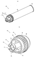
- 2A is an external perspective view of a photosensitive drum unit according to one embodiment
- FIG. 2B is an external perspective view of an end member.
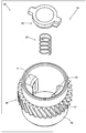
- FIG. 3 is an exploded perspective view of the bearing member.
- FIG. 4 is a view of the bearing member viewed from the axial direction.
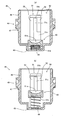
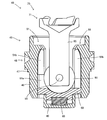
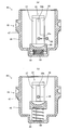
- FIG. 5A is a cross-sectional view taken along the line VV in FIG. 4 and shows a posture in which the movable base is moved to the receiving portion side.
- FIG. 5B is a cross-sectional view taken along the line VV in FIG. 4 and shows a posture in which the movable base is separated from the receiving portion side.
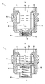
- FIG. 6A is a cross-sectional view taken along the line VI-VI in FIG. 4, and shows a posture in which the movable base is moved to the receiving portion side.
- FIG. 6B is a cross-sectional view taken along the line VI-VI in FIG. 4 and shows a posture in which the moving base is separated from the receiving portion side.
- FIG. 7A is a cross-sectional view taken along the line VII-VII in FIG. 4 and shows a posture in which the moving base is moved to the receiving portion side.
- FIG. 7B is a cross-sectional view taken along the line VII-VII in FIG. 4 and shows a posture in which the movable base is separated from the receiving portion side.
- FIG. 8A is a cross-sectional view taken along the line VIII-VIII in FIG.
- FIG. 8B is a cross-sectional view taken along the line VIII-VIII in FIG. 4 and shows a posture in which the moving base is separated from the receiving portion side.
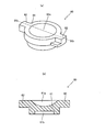
- FIG. 9A is a perspective view of the movable base, and FIG. 9B is a cross-sectional view.
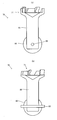
- 10A is a cross-sectional view taken along the line Xa-Xa of the shaft member shown in FIG. 2B, and FIG. 10B is taken along the line Xb-Xb of the shaft member shown in FIG.
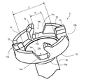
- FIG. 11 is an enlarged view of the coupling member.
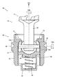
- FIG. 12 is a cross-sectional view in the axial direction of the end member along the line indicated by Xb-Xb in FIG. 13A is a view showing a posture in which the shaft member is most inclined to one side at the same viewpoint as FIG. 12, and FIG. 13B is a view showing a posture in which the shaft member is most inclined to the other side from the same viewpoint as FIG. is there.
- FIG. 14 is a view for explaining a method of attaching the shaft member to the bearing member.
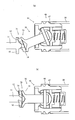
- FIG. 15A is a diagram illustrating a scene in which the rotational force transmission pin moves in the introduction groove in the first groove forming portion
- FIG. 15B is a diagram in which the rotational force transmission pin moves in the swing groove in the first groove formation portion.
- FIG. 16A is a diagram illustrating a scene in which the rotational force transmission pin moves in the introduction groove in the second groove forming portion
- FIG. 16B is a diagram in which the rotational force transmission pin moves in the swing groove in the second groove formation portion.
- FIG. 17A is a perspective view showing the drive shaft and pins of the image forming apparatus main body and the drive shaft
- FIG. 17B is a view for explaining the posture in which the pins are connected to the coupling member. is there.
- FIG. 18A is a diagram for explaining an example of one scene where the process cartridge is mounted on the apparatus main body
- FIG. 18A is a diagram for explaining an example of one scene where the process cartridge is mounted on the apparatus main body
- FIG. 18B is a diagram for explaining an example of another scene where the process cartridge is mounted on the apparatus main body.
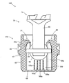
- FIG. 19A is a perspective view of a bearing member according to another embodiment
- FIG. 19B is a view of the bearing member as viewed from the direction in which the shaft member is inserted in the axial direction.
- FIG. 20 is a cross-sectional view taken along the line XX-XX shown in FIG.
- FIG. 21 is a sectional view in the axial direction of the end member and corresponds to FIG.
- FIG. 22 is a view for explaining a method of attaching the shaft member to the bearing member from the same viewpoint as FIG.
- FIG. 23 is a perspective view of a shaft member among end members according to another embodiment.
- FIG. 1 is a diagram illustrating one embodiment.
- apparatus main body 10 an image forming apparatus main body 10
- FIG. 1 the process cartridge 20 can be attached to and detached from the apparatus main body 10 by moving in the direction indicated by A in FIG. This direction is different from the axial direction of the drive shaft of the apparatus main body 10.
- the apparatus main body 10 and the process cartridge 20 constitute an image forming apparatus. This will be described in detail below.
- the process cartridge 20 has a casing 21 that forms the outline of the process cartridge 20, and various parts are contained inside the casing 21. Specifically, in this embodiment, in addition to the photosensitive drum unit 30 (see FIG. 2A), a charging roller, a developing roller, a developing blade, a transfer roller, and a cleaning blade are provided.
- the photosensitive drum unit 30 is formed with characters, figures and the like to be transferred to a recording medium such as paper.
- FIG. 2A shows an external perspective view of the photosensitive drum unit 30.
- the photosensitive drum unit 30 includes a photosensitive drum 35, a lid member 36, and an end member 40.
- FIG. 2B is a perspective view focusing on the end member 40.
- the photosensitive drum unit 30 will be described with reference to FIG. 2A and FIG.
- the photosensitive drum 35 is a member in which a photosensitive layer is coated on the outer peripheral surface of a cylindrical drum cylinder. That is, the drum cylinder is configured by applying a photosensitive layer to a conductive cylinder such as aluminum. An end member 40 is attached to one end of the photosensitive drum 35 as will be described later, and a lid member 36 is disposed at the other end.
- the drum cylinder is cylindrical, but it may be solid columnar. However, at least the lid member 36 and the end member 40 are formed so as to be appropriately attached to the end portions.
- the lid member 36 is a member formed of resin, and a fitting portion that is inserted inside the cylinder of the photosensitive drum 35 and a bearing portion that is disposed so as to cover one end surface of the photosensitive drum 35 are formed coaxially.
- the bearing portion has a disk shape that covers the end surface of the photosensitive drum 35 and includes a portion that receives the shaft.
- a ground plate made of a conductive material is disposed on the lid member 36, thereby electrically connecting the photosensitive drum 35 and the apparatus main body 10.
- a gear for transmitting rotational force may be disposed on the lid material.
- the said electroconductive material may be provided in the edge part member 40 side mentioned later.
- the end member 40 is a member that is attached to the end of the photosensitive drum 35 opposite to the lid member 36 and includes a bearing member 45 and a shaft member 70.
- the bearing member 45 is a member fixed to the end portion of the photosensitive drum 35.
- FIG. 3 shows an exploded perspective view of the bearing member 45.
- FIG. 4 is a plan view of the bearing member 45 as viewed from the axial direction (the side on which the shaft member 70 is inserted).
- 5 is a cross-sectional view taken along line VV in FIG. 4
- FIG. 6 is a cross-sectional view taken along line VI-VI
- FIG. 7 is shown along line VII-VII.
- FIG. 8 is a cross-sectional view taken along the line VIII-VIII.
- the bearing member 45 includes a cylindrical body 46 that is cylindrical as can be seen from FIGS. 2 to 8. Further, on the outer peripheral surface of the cylindrical body 46, a ring-shaped contact wall 47 and a gear 48 are formed so as to stand along the outer peripheral surface.
- the outer diameter of the cylindrical body 46 is substantially the same as the inner diameter of the photosensitive drum 35, and one end side of the cylindrical body 46 is inserted into the photosensitive drum 35 to fit the bearing member 45 to the photosensitive drum 35. To fix. In this case, the photosensitive drum 35 is inserted to a depth where the end surface of the photosensitive drum 35 is brought into contact with the contact wall 47. At this time, an adhesive may be used for stronger attachment.
- corrugation may be provided in the cylindrical body 46 of the part by which an adhesive agent is arrange
- the gear 48 is a gear that transmits rotational force to other rollers such as a developing roller, and is a helical gear.
- the type of gear is not particularly limited and may be a spur gear or the like. However, the gear is not necessarily provided.
- a receiving portion 49 is provided at the opening on one end side in the axial direction of the cylindrical body 46 so as to close at least a part of the opening of the cylindrical body 46.
- the receiving portion 49 is in a container shape having a concave portion as can be seen from FIGS. 5 to 8, and is configured such that one end side of the urging member can be held in contact.
- a holding portion 50 is included inside the cylindrical body 46.
- the end of the cylindrical body 46 opposite to the receiving portion 49 is open, and the shaft member 70 is attached from here.
- the holding part 50 is a part for forming predetermined introduction grooves 51 a and 55 a and swinging grooves 51 b and 55 b inside the cylindrical body 46, and the first groove forming part 51 and the second groove forming part 55 are provided.
- the holding unit 50 includes a moving base 60 and an urging member 69.
- the holding portion 50 includes two (a pair) groove forming portions (51, 55) provided to face each other will be described, but not limited thereto, four (two pairs) groove forming portions, Six (three pairs) groove forming portions may be provided or more.
- the first groove forming part 51 is a part for forming the introduction groove 51a and the swing groove 51b.
- the first groove forming portion 51 has two block-shaped first protrusions so as to protrude from the inner peripheral surface of the cylindrical body 46. It has a part 52 and a second convex part 53.
- the first convex portion 52 and the second convex portion 53 are both arranged with a predetermined interval along the circumferential direction of the cylindrical body 46 with the direction along the axial direction of the cylindrical body 46 being the longitudinal direction. Yes.
- This gap becomes the swing groove 51b. Therefore, the swing groove 51 b is a groove extending along the axial direction of the cylindrical body 46. Further, as can be seen from FIGS.
- the bottom surface 51c of the swing groove 51b has a curved surface 51d that is curved with respect to the direction along the axial direction of the cylindrical body 46 on the end side opposite to the receiving portion 49. In this embodiment, it has an arc shape. And the space
- the first convex portion 52 is provided with an introduction groove 51a on the receiving portion 49 side, where the first convex portion 52 is cut out along the circumferential direction of the cylindrical body 46, and one of the first convex portion 52 communicates with the other.
- the introduction groove 51a forms a groove that communicates from the swing groove 51b to the opposite side (the outside of the holding part 50) across the first convex part 52.
- the second groove forming portion 55 is provided at a position facing the first groove forming portion 51 on the opposite side in the radial direction of the cylindrical body 46.
- the second groove forming part 55 is a part for forming the introduction groove 55a and the swing groove 55b.
- the second groove forming portion 55 has two block-shaped first protrusions so as to protrude from the inner peripheral surface of the cylindrical body 46.
- a portion 56 and a second convex portion 57 are provided.
- the first convex portion 56 and the second convex portion 57 are both arranged with a predetermined interval along the circumferential direction of the cylindrical body 46 with the direction along the axial direction of the cylindrical body 46 being the longitudinal direction. Yes.
- the rocking groove 55 b is a groove extending along the axial direction of the cylindrical body 46.
- the bottom surface 55c of the swing groove 55b has a curved surface 55d that is curved toward the end along the axial direction of the cylindrical body 46 on the end opposite to the receiving portion 49. In this embodiment, it has an arc shape.
- fluctuation groove is narrowed by the said curved surface 55d and the curved surface 51d of the bottom face 51c of the rocking
- the arc of the curved surface 55d preferably belongs to the same circle as the circle including the arc of the curved surface 51d of the swing groove 51b. Therefore, in this embodiment, as shown in FIGS. 7 and 8, the distance between the bottom surface 51c and the bottom surface 55c in the axial section including the bottom surfaces 51c and 55c is curved on the end side where the shaft member 70 is inserted (see FIG. 8). The space between 51d and curved surface 55d is formed to be narrow.
- the first convex portion 56 is provided with an introduction groove 55a that cuts out the first convex portion 56 along the circumferential direction of the cylindrical body 46 and communicates one of the first convex portion 56 and the other. Accordingly, the introduction groove 55a forms a groove that communicates from the swing groove 55b to the opposite side (outside of the holding part 50) across the first convex part 56.
- the moving pedestal 60 is a member that is arranged so as to be movable inside the cylindrical body 46 and configured to receive the sphere 90 (see FIG. 10) of the shaft member 70.
- 3 to 8 show the shape of the movable pedestal 60 at each viewpoint.
- FIG. 9 shows the form of the movable pedestal 60.
- FIG. 9A is a perspective view
- FIG. 9B is an axial sectional view taken along the line IXb-IXb in FIG. 9A.
- the movable pedestal 60 includes a disc-shaped main body 61 having a predetermined thickness, and a recess 61a having a spherical bottom is formed on one surface thereof. Yes. Since the spherical body 90 of the shaft member 70 contacts here as will be described later, it is preferable that the spherical surface of the recess 61 a is along the spherical surface of the spherical body 90. Further, a cylindrical recess 61 b is formed on the other surface of the main body 61. Here, one end of the urging member 69 is held as will be described later.
- a guide portion 62 is provided so as to protrude radially outward from one of the radial directions of the main body 61 and the other from a part of the outer peripheral surface that is an edge portion of the main body 61.
- the guide portion 62 is disposed inside the rocking grooves 51b and 55b, and is sized to move within the rocking grooves 51b and 55b.
- the movable pedestal only needs to be able to receive and receive the proximal end portion of the shaft member, and it is not always necessary to provide a spherical recess as in this embodiment.
- the recess may have other forms, or the recess itself may not be present. Furthermore, it can also be made convex instead of the depression.
- the urging member 69 is a means that can urge the cylindrical body in the axial direction, and urges the shaft member 70 in the axial direction when the shaft member 70 is combined with the bearing member 45.
- the shaft member 70 is urged through the moving pedestal 60 so that the moving pedestal 60 is cylindrical as the moving pedestal 60 moves.
- the body 46 is urged in the axial direction.
- the urging member is a so-called coil spring as can be seen from FIGS.
- the urging member is not particularly limited as long as the urging member can urge and hold the moving base 60 as will be described later, and an elastic material such as elastic rubber is used. A member may be used.
- the moving pedestal 60 and the urging member 69 described above are arranged inside the cylindrical body 46 as follows and function as a part of the holding portion 50. That is, as can be seen from FIGS. 5 to 8, the movable pedestal 60 has a cylindrical shape such that the concave portion 61 b faces the receiving portion 49 side and the depression 61 a faces the opening of the cylindrical body 46 on the side opposite to the receiving portion 49. Located inside the body 46. At this time, as can be seen from FIG. 7 and FIG. 8, the protruding guide part 62 of the moving base 60 is located inside the swing groove 51 b of the first groove forming part 51 and the swing groove of the second groove forming part 55. 55 is inserted inside the swing groove 55b.
- the mounting of the movable pedestal 60 to the cylindrical body 46 can be performed in the same procedure as the mounting of the shaft member 70 described later to the bearing member 45.
- the urging member 69 is disposed between the receiving portion 49 of the cylindrical body 46 and the moving base 60, one end side in the urging direction is held in contact with or fixed to the receiving portion 49, and the other end side in the urging direction is held. It arrange
- the movable base 60 and the biasing member 69 can take the following posture. That is, by pressing the moving base 60 against the receiving portion 49 against the urging force of the urging member 69, the urging member 69 is compressed as shown in each of FIGS. Thus, the movable pedestal 60 is brought closer to the receiving portion 49 side.
- the introduction groove 51a and the introduction groove 55a are on the opening side of the moving base 60 (the upper side of the drawing in FIGS. 5 to 8, the side of the moving base 60 on which the urging member 69 is disposed). Appears on the opposite side), and some member can be passed through here.
- the urging member 69 expands, and the moving base 60 moves away from the receiving portion 49 side and opens. Close to the side.
- the introduction groove 51a and the introduction groove 55a are on the opening side of the moving base 60 (the upper side of the drawing in FIGS. 5 to 8, the side of the moving base 60 on which the urging member 69 is disposed).
- the size appearing on the opposite side is concealed by the moving base 60 and becomes smaller. Thereby, as described later, the rotational force transmission pin 95 cannot pass through the introduction groove 51a and the introduction groove 55a.
- the holding portion 50 is a space (space) surrounded by the first groove forming portion 51, the second groove forming portion 55, and the moving base 60 as shown by 50a in FIGS. 50a) is formed.
- a spherical body 90 of the shaft member 70 is disposed in the space 50a as described later. The relationship with the shaft member 70 will be described in detail later.
- the material constituting the cylindrical body of the bearing member 45, the first groove forming portion 51, the second groove forming portion 52, and the moving pedestal 60 is not particularly limited, but a resin such as polyacetal, polycarbonate, or PPS is used. Can do. Here, in order to improve the rigidity of a member, you may mix
- FIG. 10A is a cross-sectional view taken along the line Xa-Xa of the shaft member 70 shown in FIG. 2B
- FIG. 10B is an Xb of the shaft member 70 shown in FIG. 2B.
- Cross-sectional views along -Xb are shown.
- the shaft member 70 includes a coupling member 71, a rotation shaft 85, a spherical body 90, and a rotational force transmission pin 95.
- the coupling member 71 is a part that functions as a rotational force receiving portion that receives the rotational driving force from the apparatus main body 10 (see FIG. 1).
- FIG. 11 shows an enlarged view of the coupling member 71.
- the coupling member 71 is a circular dish-like member, and a conical recess 73a is provided on the inner side so that the portion through which the axis passes is deepest. It has a bottom 73.
- a cylindrical engagement wall 74 is erected along the edge of the surface of the bottom portion 73 on the one surface side (the side opposite to the side on which the rotation shaft 85 is provided).
- the engagement wall 74 is provided with two pairs of grooves 74 a and 74 b that are provided to face each other with the axis of the shaft member 70 interposed therebetween.
- One pair of grooves 74a and the other pair of grooves 74b are offset by 90 degrees.
- a convex portion 75 is provided on one side wall of the groove, and a recess 75a is provided in the circumferential direction on the bottom 73 side.
- the pins 12 and 12 of the drive shaft 11 of the apparatus main body 10 engage with the recess 75a, and the rotational force is appropriately transmitted while preventing the removal (see FIG. 17B).
- a slope 74c is formed on the other side wall of each of the grooves 74a and 74b to facilitate the introduction of the pin 12 into the groove.
- the width of the groove 74a indicated by D in FIG. 11 is slightly larger than the diameter of the pin 12 (see FIG. 17B), and is narrower than the drive shaft 11 so that the drive shaft 11 cannot pass through. ing. Further, the inner diameter of the engagement wall 74 indicated by E in FIG. 11 is slightly larger than the diameter of the drive shaft 11, but is approximately the same. How the rotational force can be received from the drive shaft 11 will be described later.
- the number of grooves in the engagement wall is four (two pairs), but the number is not particularly limited, and there are two (one pair), six (three pairs), or more. May be.
- the rotary shaft 85 is a columnar shaft-shaped member that functions as a rotational force transmitting portion that transmits the rotational force received by the coupling member 71. Accordingly, the coupling member 71 is provided at one end of the rotating shaft 85.
- the spherical body 90 functions as a base end portion.
- the spherical body 90 is a spherical member as shown in FIG. 10. It is equipped. At this time, it is preferable that the axis of the rotary shaft 85 and the center of the sphere 90 are matched as much as possible. Thereby, the stable rotation of the photosensitive drum 35 can be obtained.
- the diameter of the sphere 90 is the narrowest part of the portion sandwiched between the holding parts 50 of the bearing member 45 described above (the narrowest part in the interval between the first groove forming part 51 and the second groove forming part 55 in this embodiment). It is almost the same. As is clear from the above, the movement of the shaft member 70 in the removal direction of the sphere 90 is not restricted by the holding portion 50 of the bearing member 45.
- the base end portion is a normal sphere
- the present invention is not limited to this.
- the base end portion may be formed by combining curved surfaces like an egg shape.
- the rotational force transmission pin 95 is a cylindrical shaft-shaped member that passes through the center of the sphere 90 and is disposed so that both ends thereof protrude from the sphere 90 through the sphere 90.
- the axis of the rotational force transmission pin 95 is provided so as to be orthogonal to the axis of the rotary shaft 85.
- the material of the shaft member 70 is not particularly limited, but resins such as polyacetal, polycarbonate, and PPS can be used. However, in order to improve the rigidity of the member, glass fiber, carbon fiber, or the like may be blended in the resin according to the load torque. Further, a metal may be inserted into the resin to further increase the rigidity, or the whole may be made of metal.
- FIG. 12 is a sectional view in the axial direction of the end member 40 along the line indicated by Xb-Xb in FIG. 2B.
- FIG. 13A is a side view of the shaft member 70 on one side from the same viewpoint as FIG.
- FIG. 13B shows the most inclined posture
- FIG. 13B shows the posture in which the shaft member 70 is most inclined to the other side from the same viewpoint as FIG.
- the shaft member 70 is in the posture in which the movable pedestal 60 is in each (b) of FIGS. 5 to 8, that is, the movable pedestal 60 is separated from the receiving portion 49 by the urging force of the urging member 69. Then, in a posture close to the opening side, a space 50a in which the sphere 90 of the shaft member 70 is surrounded by the first groove forming portion 51, the second groove forming portion 55, and the moving pedestal 60 of the holding portion 50 (FIG. 7, FIG. 8). Further, both end portions of the rotational force transmitting pin 95 protruding from the sphere 90 are inserted inside the swing groove 51 b of the first groove forming portion 51 and the swing groove 55 b of the second groove forming portion 55. As a result, the shaft member 70 is held by the bearing member 45.
- the shaft member 70 rotates (swings) about the axis of the rotational force transmission pin 95 as indicated by XIIa in FIG. can do. That is, it is possible to turn (swing) in the front / back direction of FIG. Furthermore, as shown by XIII in FIGS. 13 (a) and 13 (b), the shaft member 70 has a direction orthogonal to the rotation (swing) shown by XIIa, that is, the rotational force transmission pin 95. It can also be rotated (swinged) in the direction in which the axis itself swings. This is made possible by moving both end portions of the rotational force transmission pin 95 in the swing grooves 51b and 55b.
- the shaft member 70 is as shown in FIGS. 13 (a) and 13 (b). Even if it swings, it is possible to prevent the shaft member 70 from moving so as to be greatly shaken in the axial direction and in a direction perpendicular to the axial direction (the left-right direction in FIG. 13A and FIG. 13B). More specifically, the curved surfaces 51 d and 55 d of the swing grooves 51 b and 55 b are arcuate as described above, but the arc is centered on the rotation center of the shaft member 70. The diameter of the arc is preferably substantially the same as the length of the rotational force transmission pin 95. Thereby, the shake of the shaft member 70 can be suppressed.
- the shaft member 70 when receiving a driving force from the apparatus main body 10, the shaft member 70 receives a rotational force about the axis as indicated by XIIb in FIG. At this time, both end portions of the rotational force transmission pin 95 of the shaft member 70 are caught on the groove side surfaces (groove side walls) of the swing groove 51b of the first groove forming portion 51 and the swing groove 55b of the second groove forming portion 55, The rotational force can be transmitted to the bearing member 45 and the photosensitive drum 35.
- the shaft member 70 receives a force in a direction in which the shaft member 70 is detached from the bearing member 45 as indicated by XIIc in FIG.
- the bottoms of the swinging grooves 51b and 55b have the curved surfaces 51d and 55d as described above, and they face each other toward the opening (the upper end of the paper in FIG. 12, the end opposite to the receiving portion 49). Is configured to be narrow, and this interval is narrower than the length of the rotational force transmission pin 95.
- the rotational force transmission pin when the shaft member 70 insertion side of the bearing member 45 is set upward. At least a part of 95 is above the introduction grooves 51a and 55a.
- the introduction grooves 51 a and 55 a all transmit the rotational force in a posture in which the shaft member 70 transmits the rotational force.
- the pin 95 is disposed at a position to be lower than all or a part of the pin 95.
- the movable pedestal 60 is further in the postures (b) of FIGS.
- the introduction grooves 51 a and 55 a are hidden by the movable pedestal 60. Accordingly, since the rotational force transmission pin 95 cannot enter the introduction grooves 51a and 55a, the shaft member 70 may be unexpectedly detached from the bearing member 45, and the swinging as shown in FIG. Absent. Therefore, unintentional removal of the shaft member 70 is prevented, and smooth swinging is possible.
- the introduction grooves 51a and 55a are concealed when the postures of FIGS. 12 and 13 are in the posture, the introduction grooves 51a and 55a are arranged on the downstream side in the axial rotation direction even if the introduction grooves 51a and 55a are arranged on the upstream side in the axial rotation direction. There is no possibility that the shaft member 70 may come off. That is, in this embodiment, the first convex portions 52 and 56 (see FIGS. 5 and 6) may have introduction grooves, and the second convex portions 53 and 57 (see FIGS. 5 and 6) have introduction grooves. May be.
- FIG. 14 to FIG. 16 show diagrams for explanation.
- FIG. 14 is an axial sectional view showing a scene when the shaft member 70 is attached to the bearing member 45.
- FIGS. 15 and 16 are diagrams for explaining the movement of the rotational force transmission pin 95 at the time of attachment, in which the positions of the rotational force transmission pins 95 are represented by hatched circles.
- FIG. 15 focuses on the first groove forming portion 51
- FIG. 16 focuses on the second groove forming portion 55.
- the rotational force transmitting pin 95 is disposed in the introduction grooves 51a and 55a.
- FIGS. 15 (b) and 16 (b) show a scene where the rotational force transmission pin 95 moves within the swing grooves 51b and 55b, respectively.
- the shaft member 70 is placed on the spherical body 90 side so that the rotational force transmission pin 95 is outside the first groove forming portion 51 and the second groove forming portion 55. It inserts inside from the opening side of the shaped body 46. At this time, the moving base 60 is pressed in the axial direction by the shaft member 70, compressed against the urging force of the urging member 69, and moved so as to approach the receiving portion 49. 14 and FIGS. 5 to 8, the introduction grooves 51 a and 55 a of the first groove forming portion 51 and the second groove forming portion 55 are energized in the moving base 60. It appears greatly on the side opposite to the side where the member 69 is disposed.
- the shaft member 70 is rotated around the axis from the above posture. Then, as shown in FIGS. 15A and 16A, the end portions of the rotational force transmitting pins 95 protruding from the sphere 90 move in the introduction grooves 51 a and 55 a, respectively, and the first groove forming portion 51. Then, it moves from the outside of the second groove forming portion 55 into the swing grooves 51b and 55b.
- the bearing member 45 it is possible to attach the shaft member 70 to the bearing member 45 without having to forcibly insert and remove it. Further, the shaft member 70 may be removed from the bearing member 45 in the reverse manner, and can be easily removed, and reuse and recycling can be performed smoothly.
- the shaft member 70 can be attached to the bearing member 45 after the bearing member 45 is attached to the photosensitive drum 35. Therefore, it is possible to avoid attaching the end member to the photosensitive drum in a relatively unstable state where there is a swinging member. That is, the end member 40 can be attached to the photosensitive drum 35 as follows, for example. Of the end member 40, the bearing member 45 is first fitted into the photosensitive drum 35. At this time, the rotating (swinging) shaft member 70 is not attached to the bearing member 45, so that the bearing member 45 can be easily and stably pushed into the photosensitive drum 35. Thereafter, the shaft member 70 is attached to the bearing member 45 attached to the end of the photosensitive drum 35. The shaft member 70 can be easily attached as described above and can be performed without being pushed in with a large force. Therefore, when the shaft member is combined with the bearing member, it is not necessary to bend the bearing member.
- Such an end member 40 can appropriately apply a rotational force to the photosensitive drum 35 when the process cartridge 20 is mounted, and can easily attach and detach the process cartridge 20.
- the charging roller, the developing roller, the developing blade, the transfer roller, and the cleaning blade which are other configurations provided inside the casing 21 of the process cartridge 20, are as follows.
- the charging roller charges the photosensitive drum 35 by applying a voltage from the apparatus main body 10. This is performed by the charging roller rotating following the photosensitive drum 35 and contacting the outer peripheral surface of the photosensitive drum 35.
- the developing roller is a roller that supplies developer to the photosensitive drum 35.
- the electrostatic latent image formed on the photosensitive drum 35 is developed by the developing roller.
- the developing roller contains a fixed magnet.
- the developing blade is a blade that adjusts the amount of developer adhering to the outer peripheral surface of the developing roller and imparts triboelectric charge to the developer itself.
- the transfer roller is a roller for transferring an image formed on the photosensitive drum 35 to a recording medium such as paper.
- the cleaning blade is a blade that contacts the outer peripheral surface of the photosensitive drum 35 and removes the developer remaining after the transfer by the tip.
- Each of the above rollers is housed inside the housing 21 so as to be rotatable. That is, each roller rotates inside the housing 21 as necessary to exert its function.
- at least the coupling member 71 of the shaft member 70 of the photosensitive drum unit 30 is disposed so as to be exposed from the housing 21. Accordingly, as described later, a rotational driving force can be obtained from the apparatus main body 10 and the apparatus main body 10 and the process cartridge 20 can be easily attached and detached.
- each roller and blade provided in the process cartridge 20 has been described, but the members provided here are not limited thereto, and other members, parts, developer, etc. that are normally provided in the process cartridge Is preferably provided.
- the apparatus main body 10 of this embodiment is a laser printer.
- the laser printer operates in a posture in which the process cartridge 20 is mounted, and when forming an image, the photosensitive drum 35 is rotated and charged by a charging roller. In this state, laser light corresponding to the image information is irradiated to the photosensitive drum 35 using various optical members provided therein, and an electrostatic latent image based on the image information is obtained. This latent image is developed by a developing roller.
- a recording medium such as paper is set in the apparatus main body 10 and conveyed to a transfer position by a feed roller, a conveyance roller or the like provided in the apparatus main body 10.
- a transfer roll is disposed at the transfer position.
- a voltage is applied to the transfer roll as the recording medium passes, and an image is transferred from the photosensitive drum 35 to the recording medium.
- the image is fixed to the recording medium by applying heat and pressure to the recording medium.
- the recording medium on which the image is formed is discharged from the apparatus main body 10 by a discharge roll or the like.
- the apparatus main body 10 gives a rotational driving force to the photosensitive drum unit 30 in the posture in which the process cartridge 20 is mounted. Therefore, how the rotational driving force is applied from the apparatus main body 10 to the photosensitive drum unit 30 in the posture in which the process cartridge 20 is mounted will be described.
- FIG. 17A shows the shape of the tip of the drive shaft 11.
- the drive shaft 11 is a cylindrical shaft member whose tip is a hemispherical surface, and a circle as a rotational force applying portion that protrudes in a direction perpendicular to the rotation axis indicated by the alternate long and short dash line.
- a columnar pin 12 is provided.
- a gear train is formed on the opposite side of the drive shaft 11 from the tip end side shown in FIG. 17A so that the drive shaft 11 can be rotated about the axis, via which a drive source is provided. Is connected to the motor.
- the drive shaft 11 is disposed so as to project on the movement track of the attachment / detachment substantially perpendicular to the moving direction for attaching / detaching the process cartridge 20 to / from the apparatus main body 10 shown in FIG.
- the drive shaft 11 only rotates without moving in the axial direction. Therefore, when attaching or detaching the process cartridge 20, it is necessary to engage and disengage the shaft member 70 from such a drive shaft 11. According to the end member 40 described above, the engagement and disengagement between the shaft member 70 and the drive shaft 11 is facilitated. A specific manner of attachment / detachment will be described in detail later.
- FIG. 17B shows a scene where the coupling member 71 of the end member 40 is engaged with the drive shaft 11.
- the drive shaft 11 and the coupling member 71 are engaged with each other so that the axis of the drive shaft 11 and the axis of the coupling member 71 coincide with each other.
- the pin 12 of the drive shaft 11 is disposed inside the facing groove 74a or the groove 74b of the coupling member 71 (in FIG. 17B, the case is disposed inside the groove 74a).
- the coupling member 71 rotates following the rotation of the drive shaft 11, and the photosensitive drum unit 30 rotates.
- the posture in which the rotational force is transmitted is such that the axes of the drive shaft 11 and the coupling member 71 are arranged coaxially, and the pins 12 and 12 are grooves 74a, 74a or 74b of the coupling member 71.
- the posture is inside 74b.
- FIG. 18A is a view showing one scene where the end member 40 is engaged with the drive shaft 11
- FIG. 18B is another view where the end member 40 is engaged with the drive shaft 11.
- FIG. 18 the order of the operation is shown in FIGS. 18 (a) and 18 (b), and the left and right sides of the paper face the axis direction. Further, this is a scene where the process cartridge 20 is moved downward in the drawing to be mounted.
- the coupling member 71 of the shaft member 70 is inclined to the drive shaft 11 side.
- This posture is preferably a posture in which the shaft member 70 is most inclined.
- the tip of the drive shaft 11 comes into contact with the inside of the bottom 73 of the coupling member 71 and the engaging wall 74.
- the drive shaft 11 that is in contact with the coupling member 71 is rotated so as to raise the inclined shaft member 70.
- the pins 12 and 12 are inserted inside the grooves 74a and 74a. Further, by pushing the process cartridge 20 in the mounting direction, as shown in FIG.
- the axis of the tilted shaft member 70 coincides with the axis of the drive shaft 11, and the drive shaft 11 and the shaft member 70 are aligned.
- the axes of the bearing member 45 and the photosensitive drum 35 coincide with each other in the posture shown in FIG. Accordingly, a rotational force is appropriately applied from the drive shaft 11 to the shaft member 70, the bearing member 45, and the photosensitive drum 35, and finally a rotational force is applied to the process cartridge 20.
- the process cartridge 20 can be detached from the apparatus main body 10 so as to be pulled out in a direction different from the axial direction of the drive shaft 11 of the apparatus main body 10, and can be mounted on the apparatus main body 10 so as to be pushed in.
- 19 and 20 are diagrams for explaining other embodiments.
- 19A is a perspective view of the bearing member 145
- FIG. 19B is a view of the bearing member 145 as seen from the direction in which the shaft member 70 is inserted in the axial direction.
- FIG. 20 is a cross-sectional view taken along the line XX-XX shown in FIG.
- the holding part 150 is a part for forming predetermined introduction grooves 51 a and 55 a and swinging grooves 51 b and 55 b inside the cylindrical body 46, and the first groove forming part 51 and the second groove forming part 55 are provided. Have. Furthermore, the holding part 150 does not have a moving base and is provided with a biasing member 169. Here, since the first groove forming portion 51 and the second groove forming portion 55 are the same as the bearing member 45, the description thereof is omitted.
- the biasing member 169 is a means capable of biasing in the axial direction, and biases the shaft member 70 in the axial direction when the shaft member 70 is combined with the bearing member 145.
- the urging member 169 is arranged so that the four rubber plates 169a face each other at a predetermined interval.
- the rubber plate 169a is configured like a rib that is erected in the axial direction from the inner surface of the cylindrical body 46 in the receiving portion 49 so that the plate surface is in the axial direction.
- the number of the rubber plates 169a is not particularly limited.
- the rubber plate 169a is formed of elastic rubber, but may be formed of other materials as long as it is an elastic member.
- Examples of this include a thin plate of resin or metal.
- the rubber plate 169a is erected and used like a rib.
- the present invention is not limited to this, and an elastically deformable shape can be adopted. According to such an urging member 169, the shaft member 70 can be brought into direct contact with the urging member 169 as described later, and the number of parts can be reduced.
- the holding portion 150 has a space (space 150a) surrounded by the first groove forming portion 51, the second groove forming portion 55, and the urging member 169, as indicated by 150a in FIG. It is formed.
- the spherical body 90 of the shaft member 70 is disposed in the space 150a.
- FIG. 21 is a sectional view in the axial direction of the end member 140 and corresponds to FIG.
- the shaft member 70 is placed on and in contact with the tip of the rubber plate 169 a of the biasing member 169 and is disposed in the space 150 a (see FIG. 20).
- both end portions of the rotational force transmitting pin 95 protruding from the sphere 90 are inserted inside the swing groove 51 b of the first groove forming portion 51 and the swing groove 55 b of the second groove forming portion 55.
- the shaft member 70 is held by the bearing member 145.
- the swinging of the shaft member 70 and the rotation of the bearing member 145 due to the rotation of the shaft member 70 are as described in the end member 40.
- the shaft member 70 when the shaft member 70 is in a posture to transmit the rotational force as shown in FIG. 21, at least a part of the rotational force transmission pin 95 is located when the side of the bearing member 145 into which the shaft member 70 is inserted is up. Above the introduction grooves 51a, 55a. That is, in the bearing member 145, when the shaft member 70 is inserted into the bearing member 145, the introduction grooves 51 a and 55 a all transmit the rotational force when the shaft member 70 transmits the rotational force.
- the pin 95 is disposed at a position to be lower than all or a part of the pin 95. Therefore, since the rotational force transmission pin 95 cannot enter the introduction grooves 51a and 55a, the shaft member 70 is not unexpectedly detached from the bearing member 145.
- a part of the rotational force transmission pin 95 may overlap with a part of the introduction grooves 51 a and 55 a from the viewpoint of FIG. 21. Therefore, in order to more reliably prevent the shaft member 70 from being unexpectedly detached from the bearing member 145, the introduction grooves 51a and 55a are preferably provided on the upstream side in the shaft rotation direction.
- FIG. 22 shows a diagram for explanation.
- FIG. 22 is an axial sectional view showing a scene when the shaft member 70 is attached to the bearing member 145.
- the shaft member 70 is moved from the opening side of the cylindrical body 46 of the bearing member 145 to the inside so that the rotational force transmission pin 95 is outside the first groove forming portion 51 and the second groove forming portion 55. Insert (see FIG. 14).
- the elastic member 169 is pressed in the axial direction by the shaft member 70, and a force is applied against the urging force of the urging member 169 to deform as shown in FIG. Accordingly, as can be seen from FIG.
- the rotational force transmission pin 95 is positioned so as to be inserted into the introduction grooves 51 a and 55 a of the first groove forming part 51 and the second groove forming part 55. Thereafter, like the end member 40, the shaft member 70 is rotated about the axis, and the rotational force is applied in accordance with the examples of FIGS. 15 (a), 16 (a), 15 (b), and 16 (b). The tip of the transmission pin 95 is disposed in the swing grooves 51b and 55b.
- the bearing member 145 has the same effect as the bearing member 45.
- it is a rib shape like the urging member of this embodiment, and if it is configured to stand upright in the axial direction, a so-called undercut portion is not formed in this portion in the axial direction, so the bearing member together with other parts It is also possible to integrally mold the. According to this, there is an advantageous effect from the viewpoint of manufacturing cost.
- FIG. 23 is a diagram for explaining still another embodiment, and shows a perspective view of the shaft member 70 ′.
- the shaft member 70 ′ includes a coupling member 71, a rotation shaft 85, a disk 90 ′, a rotational force transmission pin 95 ′, and a support shaft 96 ′.
- the disc 90 ′ is a disc-like member that functions as a base end portion, and has an end on the opposite side to the side where the coupling member 71 is disposed on one end of the rotary shaft 85. It is equipped. At this time, it is preferable that the axis of the rotary shaft 85 and the axis of the disc 90 ′ be matched as much as possible. Thereby, the stable rotation of the photosensitive drum 35 can be obtained.
- the side surface of the disc 90 ′ is spherical, and the diameter is substantially the same as the interval between the first groove forming portion 51 and the second groove forming portion 55 of the holding portion 50 of the bearing member 45 described above. .
- the rotational force transmission pin 95 ′ is parallel to the plate surface direction of the disk 90 ′, passes through the axis of the disk 90 ′, passes through the disk 90 ′, and both ends protrude from the outer peripheral surface of the disk 90 ′. It is the column-shaped shaft-shaped member arrange
- the axis of the rotational force transmission pin 95 ′ is provided so as to be orthogonal to the axis of the rotary shaft 85.
- the support shaft 96 ′ is a columnar member that functions as a base end portion standing from the plate surface on the side where the rotation shaft 85 is not disposed, of the plate surface of the disk 90 ′, and the tip thereof is hemispherical. Is formed. As a result, the tip of the support shaft 96 ′ hits the moving base 60 of the bearing member 45, and stable rotation (swing) can be obtained.
- Such a shaft member 70 ′ can be attached to the bearing member 45 in the same manner as the shaft member 70, and can be rotated (swinged) in the same manner as described above.
- a bearing member, an end member, a photosensitive drum unit, and a process cartridge that are easy to handle are provided.
Landscapes
- Physics & Mathematics (AREA)
- General Physics & Mathematics (AREA)
- Engineering & Computer Science (AREA)
- Computer Vision & Pattern Recognition (AREA)
- Electrophotography Configuration And Component (AREA)
- Discharging, Photosensitive Material Shape In Electrophotography (AREA)
Abstract
感光体ドラム35の端部に配置され、回転力を伝達する軸部材70が取り付けるための軸受部材45であって、軸受部材は、筒状体46と、筒状体の内側に配置され、軸部材が具備する回転力伝達ピン95を保持及び着脱可能に設けられた保持部50、150と、を有し、保持部は、筒状体の軸方向に沿って延び、対向して設けられる少なくとも2つの溝である揺動溝51b、55bと、一端が揺動溝に、他端が揺動溝の外側に連通するように設けられた溝である導入溝51a、55aと、を備え、軸受部材のうち軸部材が挿入される側を上としたとき、軸部材が回転力を伝達する姿勢で導入溝の全部が、回転力伝達ピンの全部又は一部より下となるべき位置に配置される。
Description
本発明は、レーザープリンタ、複写機等の画像形成装置に着脱可能に具備されるプロセスカートリッジ、該プロセスカートリッジに備えられる感光体ドラムユニット、感光体ドラムユニットの感光体ドラムに装着される端部部材、及び端部部材を構成する軸受部材に関する。
レーザープリンタ、複写機等の画像形成装置には、該画像形成装置の本体(以下、「装置本体」と記載することがある。)に対して着脱可能にプロセスカートリッジが備えられている。
プロセスカートリッジとは、文字や図形等、表されるべき内容を形成し、これを紙等の記録媒体に転写する部材であり、ここには転写する内容が形成される感光体ドラムが備えられる。従ってプロセスカートリッジには、当該感光体ドラムに転写すべき内容を形成させるための各種手段が併せて配置されている。これら手段としては例えば現像する手段、感光体ドラムを帯電する手段、感光体ドラムをクリーンニングする手段等を挙げることができる。
プロセスカートリッジとは、文字や図形等、表されるべき内容を形成し、これを紙等の記録媒体に転写する部材であり、ここには転写する内容が形成される感光体ドラムが備えられる。従ってプロセスカートリッジには、当該感光体ドラムに転写すべき内容を形成させるための各種手段が併せて配置されている。これら手段としては例えば現像する手段、感光体ドラムを帯電する手段、感光体ドラムをクリーンニングする手段等を挙げることができる。
プロセスカートリッジは、メンテナンスのために同一のプロセスカートリッジを装置本体に対して着脱したり、新たなプロセスカートリッジに交換するために古いプロセスカートリッジを装置本体から離脱し、新しいプロセスカートリッジを装置本体に装着したりする。このようなプロセスカートリッジの着脱は、画像形成装置の使用者が自らできるものであり、かかる観点からできるだけ容易に行えることが望ましい。
ところが、プロセスカートリッジに含まれる感光体ドラムには、装置本体の駆動軸が直接又は他の部材を介して係合し、これにより感光体ドラムがこの駆動軸から回転力を受けて回転するように構成されている。従って、プロセスカートリッジを装置本体に対して着脱させるためには、その都度装置本体の駆動軸と感光体ドラムとの係合の解除(離脱)、及び再係合(装着)をさせる必要がある。
ここで、感光体ドラム(プロセスカートリッジ)を装置本体の駆動軸の軸線方向に移動させて着脱することができれば、そのために装置を構成することは比較的容易である。しかしながら、画像形成装置の小型化、プロセスカートリッジの着脱スペース確保等の観点から、プロセスカートリッジを駆動軸の軸線方向とは異なる方向に引き抜くように装置本体から離脱させ、また、この方向に押し込むように装置本体に装着することが好ましい。
特許文献1には、プロセスカートリッジを装置本体の駆動軸の軸線方向とは異なる方向に着脱するための構成が開示されている。具体的には、特許文献1に記載されているカップリング部材(軸部材)は、球形部を備えることによりドラムフランジ(軸受部材)に揺動可能に取り付けられる。従って、カップリング部材に具備された、装置本体の駆動軸に係合する部分(回転力受け部材)が、球形部を中心に揺動して感光体ドラムの軸線に対して角度を変えることができ、装置本体の駆動軸と感光体ドラムとの係合離脱を容易にしている。
また、非特許文献1には、軸部材に具備される回転力伝達ピンを軸受部材に取り付けるための溝が軸受部材の内周の回転方向に設けられ、この溝により当該回転力伝達ピンの軸受部材への取り付けが容易である構造が開示されている。
日本国発明協会公開技報公技番号2010-502200号
しかしながら、特許文献1に記載のカップリング部材(軸部材)及びこれを保持するドラムフランジ(軸受部材)の構造では、カップリング部材を揺動可能としつつ球形部をドラムフランジに保持する構造とするため、球形部をドラムフランジ(軸受部材)に取り付ける際には無理入れ・無理抜きする必要があった。無理入れ・無理抜きによる組み立ては、組み立て精度の低下や、組み立て時に部品が破損する虞がある。
また、特許文献1には、カップリング部材を分解して一部の部品をドラムフランジ(軸受部材)に配置した後、カップリング部材の他の部品を順に組み立てる方法も記載されている。これによれば、無理入れ・無理抜きのような不具合はないが、工数が多くなり生産性が低下してしまう。また、このように揺動するようなカップリング部材(軸部材)が取り付けられたドラムフランジ(軸受部材)を感光体ドラムの端部に精度よく取り付けることも困難である。そして、軸部材を再利用する際に軸受部材から軸部材を取り外すにも非常に手間がかかる。
非特許文献1に記載の技術では軸受部材への軸部材の取り付け及び取り外しが容易であるが、軸部材が意図しないときに軸受部材から外れてしまう虞があった。また、軸部材の円滑な揺動、及び軸部材の装置本体との円滑な着脱を実現することが困難なことがあった。
そこで本発明は上記問題点に鑑み、軸部材の意図しない離脱を防ぎ、軸部材の円滑な揺動、回転力の伝達、及び装置本体との着脱を可能としつつ、精度よく、破損等の不具合を抑制して簡易に生産することができる、軸受部材を提供することを目的とする。またこの軸受部材を備える端部部材、感光体ドラムユニット、及びプロセスカートリッジを提供する。
以下、本発明について説明する。ここではわかりやすさのため括弧書きにて図面の参照符号を付すが、本発明はこれに限定されるものではない。
本発明は、感光体ドラム(35)の端部に配置され、回転力を伝達する軸部材(70)を取り付けるための軸受部材(45、145)であって、軸受部材は、筒状体(46)と、筒状体の内側に配置され、軸部材が具備する回転力伝達ピン(95)を保持及び着脱可能に設けられた保持部(50、150)と、を有し、保持部は、筒状体の軸方向に沿って延び、対向して設けられる少なくとも2つの溝である揺動溝(51b、55b)と、一端が揺動溝に、他端が揺動溝の外側に連通するように設けられた溝である導入溝(51a、55a)と、を備え、軸受部材のうち軸部材が挿入される側を上としたとき、軸部材が回転力を伝達する姿勢で導入溝の全部が、回転力伝達ピンの全部又は一部より下となるべき位置に配置される、軸受部材である。
本発明の軸受部材(45、145)の一態様として、保持部(50、150)は、一端側が筒状体(46)に取り付けられ、軸方向に付勢することが可能である付勢部材(69、169)を備える。
本発明の軸受部材(45、145)の一態様として、付勢部材(69)がコイルバネである。
本発明の軸受部材(45、145)の一態様として、付勢部材(169)が弾性ゴムである。
本発明の軸受部材(45)の一態様として、付勢部材(69)の他端側に移動台座(60)が配置され、移動台座が筒状体の軸方向に移動可能である。
本発明の端部部材(40、140)は、軸部材(70)、及び、本発明の軸受部材(45、145)、を有し、軸部材は、回転軸(85)と、該回転軸の一端側に具備されて画像形成装置本体の回転力付与部に係合可能とされ、該係合の姿勢で駆動軸からの回転力を受ける回転力受け部(71)と、回転軸の他端側に配置される基端部(90)と、基端部から突出する端部を有する回転力伝達ピン(95)と、を備え、軸部材は、該軸部材の回転力伝達ピンが軸受部材の揺動溝(51b、55b)内に配置されることにより軸受部材に組み合わされ、軸受部材のうち軸部材が挿入される側を上としたとき、軸部材が回転力を伝達する姿勢で回転力伝達ピンの少なくとも一部が、導入溝(51a、55a)よりも上に配置される、端部部材(40、140)である。
本発明の端部部材(40)は、軸部材(70)、及び、本発明の軸受部材(45)、を有し、軸部材は、回転軸(85)と、該回転軸の一端側に具備されて画像形成装置本体の回転力付与部に係合可能とされ、該係合の姿勢で駆動軸からの回転力を受ける回転力受け部(71)と、回転軸の他端側に配置される基端部(90)と、基端部から突出する端部を有する回転力伝達ピン(95)と、を備え、軸部材は、該軸部材の回転力伝達ピンが軸受部材の揺動溝(51b、55b)内に配置されることにより軸受部材に組み合わされるとともに、基端部が移動台座(60)に接触して配置されており、軸受部材のうち軸部材が挿入される側を上としたとき、軸部材が回転力を伝達する姿勢で回転力伝達ピンの少なくとも一部が、導入溝(51a、55a)よりも上に配置される、端部部材(40)である。
本発明の端部部材(40、140)の一態様として、軸部材(70)は、回転力伝達ピン(95)により、該軸部材の軸方向の移動が規制されている。
本発明の端部部材(40、140)の一態様として、基端部(90)は軸受部材(45、145)によっては軸方向における軸部材の抜け方向の移動が規制されない。
本発明の感光体ドラムユニット(30)は、感光体ドラム(35)と、本発明の端部部材(40、140)と、を備える。
本発明のプロセスカートリッジ(20)は、本発明の感光体ドラムユニット(30)を具備し、軸部材(70)が画像形成装置本体(10)の駆動軸に着脱可能とされる。
本発明によれば、軸部材を軸受部材に取り付けることが容易であり、かつ、取り付け後には軸部材の揺動が円滑であるとともに意図しない軸部材の抜けを防止できる。また、装置本体からの回転駆動力を感光体ドラムに伝達させることができ、プロセスカートリッジの装置本体に対する着脱も容易である。
また、軸部材を軸受部材に対して容易に着脱可能にすることができるため、揺動する軸部材を軸受部材に取り付ける前に、軸受部材を感光体ドラムに取り付けることが従来よりも適切に行える。
これに加えて、軸部材を軸受部材に取り付けるに際して、強引な着脱を必要としないので、軸部材と軸受部材との組み立ての精度低下を招かない。
また、軸部材を軸受部材に対して容易に着脱可能にすることができるため、揺動する軸部材を軸受部材に取り付ける前に、軸受部材を感光体ドラムに取り付けることが従来よりも適切に行える。
これに加えて、軸部材を軸受部材に取り付けるに際して、強引な着脱を必要としないので、軸部材と軸受部材との組み立ての精度低下を招かない。
本発明の上記した作用及び利得は、次に説明する発明を実施するための形態から明らかにされる。以下本発明を図面に示す実施形態に基づき説明する。ただし本発明はこれら実施形態に限定されるものではない。
図1は1つの形態を説明する図で、軸受部材45(図2参照)を具備するプロセスカートリッジ20、及び該プロセスカートリッジ20を装着して使用する画像形成装置本体10(以下、「装置本体10」と記載することがある。)を模式的に示した斜視図である。図1に示したようにプロセスカートリッジ20は、図1にAで示した方向に移動させることにより装置本体10に装着し、及び離脱させることができる。この方向は装置本体10の駆動軸の軸線方向とは異なる方向である。そして装置本体10及びプロセスカートリッジ20により画像形成装置とされる。以下詳しく説明する。
プロセスカートリッジ20は、その外郭を形成する筐体21を有し、その内側に各種部品が内包されている。本形態では具体的には、感光体ドラムユニット30(図2(a)参照)の他、帯電ローラ、現像ローラ、現像ブレード、転写ローラ、及びクリーニングブレードを備えている。
感光体ドラムユニット30には、紙等の記録媒体に転写すべき文字や図形等が形成される。図2(a)に感光体ドラムユニット30の外観斜視図を示した。図2(a)からわかるように感光体ドラムユニット30は、感光体ドラム35、フタ材36、及び端部部材40を備えている。図2(b)には、端部部材40に注目した斜視図を示した。以下、図2(a)、図2(b)及び適宜示す図を参照しつつ感光体ドラムユニット30について説明する。
感光体ドラム35は、円筒状であるドラムシリンダの外周面に感光層を被覆した部材である。すなわちドラムシリンダは、アルミニウム等の導電性のシリンダに感光層が塗布されて構成されている。感光体ドラム35の一端には後述するように端部部材40が取り付けられ、他端にはフタ材36が配置されている。本形態ではドラムシリンダを円筒状であるものとしたが、中実の円柱状であってもよい。ただし、少なくともフタ材36、及び端部部材40がその端部に適切に取り付けられるように形成されている。
フタ材36は、樹脂により形成された部材で、感光体ドラム35の円筒内側に挿入される嵌合部と、感光体ドラム35の一端面を覆うように配置される軸受部とが同軸に形成されている。軸受部は、感光体ドラム35の端面を覆う円板状であるとともに、軸を受ける部位を具備する。また、フタ材36には、導電性材料によりなるアース板が配置され、これにより感光体ドラム35と装置本体10とを電気的に接続させている。
なお、本形態ではフタ材の一例を表したがこれに限定されず、通常取り得る他の形態のフタ材を適用することも可能である。例えばフタ材に回転力伝達のための歯車が配置されてもよい。
また上記導電性材料は後述する端部部材40側に設けられてもよい。
なお、本形態ではフタ材の一例を表したがこれに限定されず、通常取り得る他の形態のフタ材を適用することも可能である。例えばフタ材に回転力伝達のための歯車が配置されてもよい。
また上記導電性材料は後述する端部部材40側に設けられてもよい。
端部部材40は、感光体ドラム35の端部のうち上記フタ材36とは反対側の端部に取り付けられる部材であり、軸受部材45及び軸部材70を備えている。
軸受部材45は、感光体ドラム35の端部に固定される部材である。図3には軸受部材45の分解斜視図を示した。また、図4には軸受部材45を軸方向(軸部材70が挿入される側)から見た平面図を表した。さらに、図5は図4にV-Vの線で示した矢視断面図、図6は同VI-VIの線で示した矢視断面図、図7は同VII-VIIの線で示した矢視断面図、図8は同VIII-VIIIの線で示した矢視断面図である。図5乃至図8の各図において、(a)は移動台座60が押圧され付勢部材69が圧縮されて移動台座60が下げられた場面、(b)は付勢部材69がその付勢力により伸長し、移動台座60が受け部49から離隔するように移動した場面をそれぞれ表している。
本形態では、軸受部材45は、図2乃至図8からわかるように円筒状である筒状体46を備えている。また、筒状体46の外周面には、該外周面に沿って立設するリング状である接触壁47、及び、歯車48が形成されている。筒状体46の外径は上記感光体ドラム35の内径と概ね同じであり、該筒状体46の一端側を感光体ドラム35に差し込んで嵌合することにより軸受部材45を感光体ドラム35に固定する。この際には、感光体ドラム35の端面が接触壁47に当てられる深さまで挿入される。このとき、より強固な取り付けのために接着剤を用いてもよい。また接着剤が配置される部分の筒状体46には溝や凹凸が設けられてもよい。これにより接着剤がこの溝や凹部に保持され、軸受部材45と感光体ドラム35とのさらなる強固な接着が可能となる。
歯車48は、現像ローラ等の他のローラに回転力を伝達する歯車で、はす歯歯車である。歯車の種類は特に限定されることはなく平歯車等であってもよい。ただし歯車は必ずしも設けられている必要はない。
歯車48は、現像ローラ等の他のローラに回転力を伝達する歯車で、はす歯歯車である。歯車の種類は特に限定されることはなく平歯車等であってもよい。ただし歯車は必ずしも設けられている必要はない。
筒状体46の軸方向一端側の開口部には、該筒状体46の開口部の少なくとも一部を塞ぐように受け部49が設けられている。本形態では受け部49は図5乃至図8からわかるように凹部を有する容器状であり、付勢部材の一端側が接触して保持できるように構成されている。そして、筒状体46の内側に保持部50が内包されている。一方、筒状体46のうち受け部49とは反対側の端部は開口しておりここから軸部材70を取り付ける。
保持部50は、筒状体46の内側に所定の導入溝51a、55a、揺動溝51b、55bを形成するための部位であり、第一溝形成部51、及び第二溝形成部55を有している。さらに保持部50は、移動台座60、及び付勢部材69を備えている。
本形態では、保持部50は対向して設けられる2つ(一対)の溝形成部(51、55)を備える場合を説明するが、これに限らず4つ(二対)の溝形成部、6つ(三対)の溝形成部が設けられてもよく、これより多くてもよい。
本形態では、保持部50は対向して設けられる2つ(一対)の溝形成部(51、55)を備える場合を説明するが、これに限らず4つ(二対)の溝形成部、6つ(三対)の溝形成部が設けられてもよく、これより多くてもよい。
第一溝形成部51は、導入溝51a及び揺動溝51bを形成する部位である。第一溝形成部51は、図3、図4、図5、図7、図8からわかるように、筒状体46の内周面から突出するように、2つのブロック状である第一凸部52、及び第二凸部53を有している。第一凸部52及び第二凸部53はいずれも筒状体46の軸方向に沿った方向を長手方向とし、筒状体46の周方向に沿って所定の間隔を有して配列されている。この間隙が揺動溝51bとなる。従って揺動溝51bは筒状体46の軸方向に沿って延びる溝である。さらに図7、図8からわかるように揺動溝51bの底面51cには受け部49とは反対側となる端部側に筒状体46の軸方向に沿った方向に対して湾曲した曲面51dを有し、本形態では円弧状とされている。そして当該曲面51d、及び対向する揺動溝55bの底面55cの曲面55dにより、揺動溝の底間の間隔が狭められている。
また、第一凸部52には、受け部49側に第一凸部52を筒状体46の周方向に沿って切り欠き、その一方と他方とを連通させる導入溝51aが設けられている。従って、導入溝51aにより揺動溝51bから第一凸部52を挟んだ反対側(保持部50の外側)へ連通する溝が形成される。
第二溝形成部55は、第一溝形成部51に対して筒状体46の径方向反対側に対向する位置に設けられる。
第二溝形成部55は、導入溝55a及び揺動溝55bを形成する部位である。第二溝形成部55は、図3、図4、図6、図7、図8からわかるように、筒状体46の内周面から突出するように、2つのブロック状である第一凸部56、及び第二凸部57を有している。第一凸部56及び第二凸部57はいずれも筒状体46の軸方向に沿った方向を長手方向とし、筒状体46の周方向に沿って所定の間隔を有して配列されている。この間隙が揺動溝55bとなる。従って揺動溝55bは筒状体46の軸方向に沿って延びる溝である。さらに図7、図8からわかるように揺動溝55bの底面55cには受け部49とは反対側となる端部側に筒状体46の軸方向に沿った方向に対して湾曲した曲面55dを有し、本形態では円弧状とされている。そして当該曲面55d、及び対向する揺動溝51bの底面51cの曲面51dにより、揺動溝の底間の間隔が狭められている。曲面55dの円弧は、上記した揺動溝51bの曲面51dの円弧が含まれる円と同じ円に属することが好ましい。
従って、本形態では図7、図8のように底面51c、55cを含む軸方向断面において底面51cと底面55cとの間隔は、軸部材70が挿入される(図8参照)端部側で曲面51dと曲面55dとの間が狭くなるように形成されている。
第二溝形成部55は、導入溝55a及び揺動溝55bを形成する部位である。第二溝形成部55は、図3、図4、図6、図7、図8からわかるように、筒状体46の内周面から突出するように、2つのブロック状である第一凸部56、及び第二凸部57を有している。第一凸部56及び第二凸部57はいずれも筒状体46の軸方向に沿った方向を長手方向とし、筒状体46の周方向に沿って所定の間隔を有して配列されている。この間隙が揺動溝55bとなる。従って揺動溝55bは筒状体46の軸方向に沿って延びる溝である。さらに図7、図8からわかるように揺動溝55bの底面55cには受け部49とは反対側となる端部側に筒状体46の軸方向に沿った方向に対して湾曲した曲面55dを有し、本形態では円弧状とされている。そして当該曲面55d、及び対向する揺動溝51bの底面51cの曲面51dにより、揺動溝の底間の間隔が狭められている。曲面55dの円弧は、上記した揺動溝51bの曲面51dの円弧が含まれる円と同じ円に属することが好ましい。
従って、本形態では図7、図8のように底面51c、55cを含む軸方向断面において底面51cと底面55cとの間隔は、軸部材70が挿入される(図8参照)端部側で曲面51dと曲面55dとの間が狭くなるように形成されている。
また、第一凸部56には、該第一凸部56を筒状体46の周方向に沿って切り欠き、その一方と他方とを連通させる導入溝55aが設けられている。従って、導入溝55aにより揺動溝55bから第一凸部56を挟んだ反対側(保持部50の外側)へ連通する溝が形成される。
移動台座60は、筒状体46の内側を移動可能に配置され軸部材70の球体90(図10参照)を受けることができるように構成される部材である。図3乃至図8には移動台座60の各視点における形状が表れている。また図9には移動台座60の形態を表した。図9(a)は斜視図、図9(b)は図9(a)にIXb-IXbで示した線に沿った軸方向断面図である。
これらの図にも表れているように、移動台座60は、所定の厚さを有する円板状である本体61を具備し、その一方の面には底部が球面である窪み61aが形成されている。ここには後述するように軸部材70の球体90が接触するので、窪み61aの球面は球体90の球面に沿うものであることが好ましい。また、本体61の他方の面には円柱状の凹部61bが形成されている。ここには後述するように付勢部材69の一端が保持される。
さらに、本体61の縁部分である外周面の一部からは、本体61の径方向一方と他方から径方向外側に突出するようにガイド部62が設けられている。当該ガイド部62は後述するように揺動溝51b、55bの内側に配置され、該揺動溝51b、55b内を移動できる大きさとされている。
なお、移動台座は軸部材の基端部が接触してこれを受けることができればよく、本形態のように必ずしも球面の窪みが設けられている必要はない。窪みが他の形態であってもよく、又は窪み自体がなくてもよい。さらに窪みの代わりに凸とすることもできる。
さらに、本体61の縁部分である外周面の一部からは、本体61の径方向一方と他方から径方向外側に突出するようにガイド部62が設けられている。当該ガイド部62は後述するように揺動溝51b、55bの内側に配置され、該揺動溝51b、55b内を移動できる大きさとされている。
なお、移動台座は軸部材の基端部が接触してこれを受けることができればよく、本形態のように必ずしも球面の窪みが設けられている必要はない。窪みが他の形態であってもよく、又は窪み自体がなくてもよい。さらに窪みの代わりに凸とすることもできる。
付勢部材69は筒状体の軸方向に付勢することができる手段であり、軸受部材45に軸部材70が組み合わされたときに軸部材70を軸方向に付勢する。本形態では図3乃至図8に各視点における形態が表れているように、移動台座60を介して軸部材70を付勢するため、移動台座60の移動に伴って該移動台座60を筒状体46の軸方向に付勢する。本形態で付勢部材は図3乃至図8からもわかるように、いわゆるコイルバネである。
ただし、付勢部材は後で説明するように移動台座60を付勢して保持することができれば特にその具体的態様は限定されることなく、例えば弾性ゴムのような弾性的な材料を用いた部材を用いてもよい。
ただし、付勢部材は後で説明するように移動台座60を付勢して保持することができれば特にその具体的態様は限定されることなく、例えば弾性ゴムのような弾性的な材料を用いた部材を用いてもよい。
以上説明した移動台座60及び付勢部材69は筒状体46の内側に次のように配置されて保持部50の一部として機能する。すなわち図5乃至図8からわかるように、移動台座60が、その凹部61bが受け部49側、窪み61aが筒状体46のうち受け部49とは反対側の開口部に向くように筒状体46の内側に配置される。このとき、図7、図8からわかるように、移動台座60の突出したガイド部62が、第一溝形成部51の揺動溝51bの内側、及び、第二溝形成部55の揺動溝55の揺動溝55bの内側にそれぞれ挿入される。移動台座60の筒状体46への取り付けは後述する軸部材70の軸受部材45への取り付けと同様の手順で行うことができる。
また、付勢部材69は、筒状体46の受け部49と移動台座60との間に配置され、付勢方向一端側が受け部49に接触又は固定されて保持され、付勢方向他端側が移動台座60の凹部61b内に配置されてここに接触又は固定されて保持されている。
また、付勢部材69は、筒状体46の受け部49と移動台座60との間に配置され、付勢方向一端側が受け部49に接触又は固定されて保持され、付勢方向他端側が移動台座60の凹部61b内に配置されてここに接触又は固定されて保持されている。
移動台座60及び付勢部材69の上記のような配置により、これらは次のような姿勢を取ることができる。すなわち、移動台座60を付勢部材69の付勢力に抗して受け部49側に押圧することにより、図5乃至図8の各(a)に示したように、付勢部材69が圧縮されて移動台座60が受け部49側に近付けられている。このとき、当該図からわかるように、導入溝51a及び導入溝55aが移動台座60よりも開口側(図5乃至図8の紙面上側、移動台座60のうち付勢部材69が配置された側とは反対側)に表れ、ここに何らかの部材を通すことができるようになる。
一方、移動台座60に対する押圧力を除く、又は弱めると図5乃至図8の各(b)に示したように、付勢部材69が伸長し、移動台座60が受け部49側から離れ、開口側に近付けられる。このとき、当該図からわかるように、導入溝51a及び導入溝55aが移動台座60よりも開口側(図5乃至図8の紙面上側、移動台座60のうち付勢部材69が配置された側とは反対側)に表れる大きさが、移動台座60により隠蔽されて小さくなる。これにより後述するように回転力伝達ピン95が導入溝51a、及び導入溝55aを通過することができないようになる。
一方、移動台座60に対する押圧力を除く、又は弱めると図5乃至図8の各(b)に示したように、付勢部材69が伸長し、移動台座60が受け部49側から離れ、開口側に近付けられる。このとき、当該図からわかるように、導入溝51a及び導入溝55aが移動台座60よりも開口側(図5乃至図8の紙面上側、移動台座60のうち付勢部材69が配置された側とは反対側)に表れる大きさが、移動台座60により隠蔽されて小さくなる。これにより後述するように回転力伝達ピン95が導入溝51a、及び導入溝55aを通過することができないようになる。
以上のように、保持部50は、第一溝形成部51、第二溝形成部55、及び移動台座60により、図7、図8に50aで示したように、これらに囲まれる空間(空間50a)が形成されるように構成されている。当該空間50aに後述するように軸部材70の球体90が配置される。軸部材70との関係は後で詳しく説明する。
軸受部材45の筒状体、第一溝形成部51、第二溝形成部52、移動台座60を構成する材料は特に限定されることはないが、ポリアセタール、ポリカーボネート、PPS等の樹脂を用いることができる。ここで、部材の剛性を向上させるために、負荷トルクに応じて樹脂中にガラス繊維、カーボン繊維等を配合してもよい。また、軸部材の取り付け、揺動動作を円滑にするために、樹脂にフッ素、ポリエチレン、及びシリコンゴムの少なくとも1種類を含有して摺動性を向上させてもよい。また、樹脂をフッ素コーティングしたり、潤滑剤を塗布してもよい。
図2に戻り、端部部材40のうち軸部材70について説明する。図10(a)には、図2(b)に表れた軸部材70のXa-Xaに沿った断面図、図10(b)には、図2(b)に表れた軸部材70のXb-Xbに沿った断面図をそれぞれ示した。軸部材70は、図2、図10からわかるように、カップリング部材71、回転軸85、球体90、及び回転力伝達ピン95を備えている。
カップリング部材71は、装置本体10(図1参照)からの回転駆動力を受ける回転力受け部として機能する部位である。図11にはカップリング部材71を拡大した図を示した。カップリング部材71は、図2、図10、及び図11からわかるように、円形皿状の部材であり、その内側は軸線が通る部位が最も深くなるように円錐状の凹部73aが設けられた底部73を有している。
また、底部73の面のうち、一面側(回転軸85が設けられる側とは反対側)の面の縁に沿って筒状の係合壁74が立設されている。係合壁74には軸部材70の軸線を挟んで対向して設けられる溝74a、74bが2対設けられている。一方の対の溝74aと他方の対の溝74bとは90度ずらされている。
各溝74a、74bには、図11によく表れているように、溝の一方の側壁に凸部75が設けられるとともに、その底部73側には円周方向に窪み75aを具備している。これにより後述するように装置本体10の駆動軸11のピン12、12が窪み75aに係合してその抜けが防止されつつ、適切に回転力が伝達される(図17(b)参照)。
また、各溝74a、74bの他方側の側壁には斜面74cが形成されており、上記ピン12の溝内への導入を容易にしている。
各溝74a、74bには、図11によく表れているように、溝の一方の側壁に凸部75が設けられるとともに、その底部73側には円周方向に窪み75aを具備している。これにより後述するように装置本体10の駆動軸11のピン12、12が窪み75aに係合してその抜けが防止されつつ、適切に回転力が伝達される(図17(b)参照)。
また、各溝74a、74bの他方側の側壁には斜面74cが形成されており、上記ピン12の溝内への導入を容易にしている。
従って図11にDで示した溝74aの幅はピン12の直径より若干大きくされている(図17(b)参照)とともに、駆動軸11が通過できないように、該駆動軸11よりは狭くされている。また、図11にEで示した係合壁74の内側の径は駆動軸11の直径より若干大きく形成されているが概ね同じ程度とされる。どのように駆動軸11から回転力を受けることができるかついては後で説明する。
本形態では係合壁の溝を4つ(2対)としたが、その数は特に限定されるものではなく、2つ(1対)でも、6つ(3対)でも、又はそれより多くてもよい。
回転軸85は、カップリング部材71が受けた回転力を伝達する回転力伝達部として機能する円柱状の軸状部材である。従って回転軸85の一端には上記カップリング部材71が設けられている。
球体90は、基端部として機能し、本形態では図10からわかるように球状の部材で、回転軸85の端部のうちカップリング部材71が配置される側とは反対側の端部に具備される。このとき、回転軸85の軸線と球体90の中心はできるだけ一致させることが好ましい。これにより、感光体ドラム35の安定した回転を得ることができる。また球体90の直径は上記した軸受部材45の保持部50で挟まれる部分の最も狭い部位(本形態では第一溝形成部51と第二溝形成部55との間隔のうち最も狭い部位)と概ね同じとされている。以上より明らかなように、球体90は、軸受部材45の保持部50によって軸部材70の抜け方向の移動が規制されているわけではない。
本形態では、基端部として通常の球である場合を示したが、これに限定されるものではなく、例えば卵形のように曲面が組み合わされて形成されたものであってもよい。
回転力伝達ピン95は、球体90の中心を通るとともに、該球体90を貫いて両端が球体90から突出して配置される円柱状の軸状部材である。回転力伝達ピン95の軸線は上記回転軸85の軸線と直交するように設けられている。
軸部材70の材質は特に限定されるものではないが、ポリアセタール、ポリカーボネート、PPS等の樹脂を用いることができる。ただし、部材の剛性を向上させるために、負荷トルクに応じて樹脂中にガラス繊維、カーボン繊維等を配合しても良い。また、樹脂中に金属をインサートしてさらに剛性を上げても良いし、全体を金属で製作しても良い。
上記軸受部材45と軸部材70とは次のように組み合わせられることにより、端部部材40とされている。図12には図2(b)にXb-Xbで示した線に沿った端部部材40の軸線方向断面図、図13(a)には図12と同じ視点で軸部材70が一方側に最も傾いた姿勢、図13(b)には図12と同じ視点で軸部材70が他方側に最も傾いた姿勢をそれぞれ表した。
軸部材70は、図12からわかるように、移動台座60が図5乃至図8の各(b)にある姿勢、すなわち、移動台座60が付勢部材69の付勢力により受け部49から離隔されて開口側に近付けられた姿勢において、軸部材70の球体90が保持部50の第一溝形成部51、第二溝形成部55、及び移動台座60に囲まれた空間50a(図7、図8参照)内に配置される。さらに球体90から突出した回転力伝達ピン95の両端部が、第一溝形成部51の揺動溝51b、第二溝形成部55の揺動溝55bの内側に挿入される。これにより軸部材70が軸受部材45に保持される。
このように軸部材70が軸受部材45の内側に配置されることにより、軸部材70は、図12にXIIaで示したように、回転力伝達ピン95の軸線を中心として回動(揺動)することができる。すなわち回転力伝達ピン95を中心に図12の紙面手前/奥方向に回動(揺動)することが可能である。
さらに、軸部材70は、図13(a)、図13(b)にXIIIで示したように、上記XIIaで示した回動(揺動)に直交する方向、すなわち、回転力伝達ピン95の軸線自体が揺動する方向にも回動(揺動)することができる。これは、回転力伝達ピン95の両端部がそれぞれの揺動溝51b、55b内を移動することにより可能となる。ここで、揺動溝51b、55bはその底面51c、55cのうち一部が円弧面51d、55dを有しているので、軸部材70が図13(a)、図13(b)のように揺動しても軸部材70が軸線方向、及びこれに直交する方向(図13(a)、図13(b)の紙面左右方向)に大きくぶれるように移動することを抑えることができる。
より詳しくは、揺動溝51b、55bの曲面51d、55dは上記したように円弧状であるが、当該円弧は、軸部材70の回動中心を中心としている。そしてその円弧の直径は、回転力伝達ピン95の長さと概ね一致していることが好ましい。これにより軸部材70のぶれを抑制することができる。
さらに、軸部材70は、図13(a)、図13(b)にXIIIで示したように、上記XIIaで示した回動(揺動)に直交する方向、すなわち、回転力伝達ピン95の軸線自体が揺動する方向にも回動(揺動)することができる。これは、回転力伝達ピン95の両端部がそれぞれの揺動溝51b、55b内を移動することにより可能となる。ここで、揺動溝51b、55bはその底面51c、55cのうち一部が円弧面51d、55dを有しているので、軸部材70が図13(a)、図13(b)のように揺動しても軸部材70が軸線方向、及びこれに直交する方向(図13(a)、図13(b)の紙面左右方向)に大きくぶれるように移動することを抑えることができる。
より詳しくは、揺動溝51b、55bの曲面51d、55dは上記したように円弧状であるが、当該円弧は、軸部材70の回動中心を中心としている。そしてその円弧の直径は、回転力伝達ピン95の長さと概ね一致していることが好ましい。これにより軸部材70のぶれを抑制することができる。
また、装置本体10からの駆動力を受けた時には、軸部材70は、図12にXIIbで示したようにその軸線を中心とした回転力を受ける。このときには、軸部材70の回転力伝達ピン95の両端部が第一溝形成部51の揺動溝51b、及び第二溝形成部55の揺動溝55bの溝側面(溝側壁)に引っ掛かり、回転力を軸受部材45、そして感光体ドラム35に伝達させることができる。
さらに、軸部材70が図12にXIIcで示したように軸受部材45から外れ(抜け)ようとする方向に力を受けた場合を考える。しかしながら、揺動溝51b、55bの底部は上記のように曲面51d、55dを有しており、開口部(図12の紙面上方、受け部49とは反対側の端部)に向けて両者間が狭くなるように構成され、この間隔は回転力伝達ピン95の長さより狭くなっている。従って、このように軸部材70が軸方向に引っ張られたとしても、回転力伝達ピン95が揺動溝51bの底面51cのうち曲面51d及び揺動溝55bの底面55cのうち曲面55dに引っ掛かるので軸部材70は軸受部材45から離脱しない。以上より明らかなように、回転力伝達ピン95によって軸部材70の軸方向の移動が規制される。
また、このように軸部材70が図12、図13のように回転力を伝達する姿勢にあるときには、軸受部材45のうち軸部材70が挿入される側を上としたときに回転力伝達ピン95の少なくとも一部が導入溝51a、55aよりも上にある。すなわち、軸受部材45においては、軸受部材45のうち軸部材70が挿入される側を上としたとき、軸部材70が回転力を伝達する姿勢で導入溝51a、55aの全部が、回転力伝達ピン95の全部又は一部より下となるべき位置に配置される。本形態ではさらに移動台座60が図5乃至図8の各(b)の姿勢にあり、導入溝51a、55aが移動台座60により隠蔽されている。従って回転力伝達ピン95が導入溝51a、55aに入ることができないので、不意に軸部材70が軸受部材45から外れてしまうことや、図13に示したような揺動が阻害されることがない。従って、軸部材70の意図しない抜けが防止され、円滑な揺動が可能となる。そして本形態では、図12、図13の姿勢にあるときには導入溝51a、55aが隠蔽されてしまうので、導入溝51a、55aは軸回転方向上流側に配置されていても、軸回転方向下流側に配置されていても軸部材70が外れる虞がない。すなわち、本形態では、第一凸部52、56(図5、図6参照)に導入溝があってもよく、第二凸部53、57(図5、図6参照)に導入溝があってもよい。
次に、軸部材70を軸受部材45に組み合わせる方法について説明する。図14乃至図16に説明のための図を示した。図14は軸部材70を軸受部材45に取り付ける際の一場面を表す軸方向断面図である。図15、図16は当該取り付けの際の回転力伝達ピン95の動きを説明する図であり、回転力伝達ピン95の位置をハッチングした丸印で表した図である。図15は第一溝形成部51、図16は第二溝形成部55に注目しており、図15(a)、図16(a)は回転力伝達ピン95が導入溝51a、55a内を移動する場面、図15(b)、図16(b)は回転力伝達ピン95が揺動溝51b、55b内を移動する場面をそれぞれ表している。
初めに、図14に示したように、回転力伝達ピン95が第一溝形成部51及び第二溝形成部55の外側となるように、軸部材70を球体90側を軸受部材45の筒状体46の開口側から内側に挿入する。このとき、軸部材70により移動台座60を軸方向に押圧し、付勢部材69の付勢力に抗して圧縮させ、移動台座60を受け部49に近付けるように移動させる。これにより図14や図5乃至図8の各(a)にも表れているように、第一溝形成部51及び第二溝形成部55の導入溝51a、55aが移動台座60のうち付勢部材69が配置された側とは反対側に大きく表れる。
次に上記の姿勢から軸部材70を軸中心に回転させる。すると、図15(a)、図16(a)に示したように、球体90から突出した回転力伝達ピン95の端部がそれぞれ導入溝51a、55a内を移動し、第一溝形成部51、第二溝形成部55の外側から揺動溝51b、55b内へ移動する。
これにより回転力伝達ピン95の端部が揺動溝51a、55aの内側に達したあと、図15(b)、図16(b)に示したように、軸部材70に負荷していた押圧力を除し、又は弱めることで付勢部材69が付勢力により伸長し、移動台座60が受け部49から離隔するように移動してこれに伴い軸部材70も移動する。このとき、回転力伝達ピン95の端部は揺動溝51a、55aの内側を移動する。
以上により図12に示した姿勢となる。
以上により図12に示した姿勢となる。
以上のように、軸受部材45によれば、軸部材70を無理入れ及び無理抜きする必要がなく軸受部材45に取り付けることができる。また、軸部材70の軸受部材45からの取り外しも上記と逆を行えばよく、容易に取り外しをすることができ、リユース、リサイクルも円滑に行うことが可能である。
また、このような軸部材70の軸受部材45への取り付けは軸受部材45を感光体ドラム35に取り付けてから行うことができる。従って揺動する部材があるという比較的不安定な状態で端部部材を感光体ドラムに取り付けることを回避することも可能である。すなわち端部部材40は、例えば次のように感光体ドラム35に取り付けることができる。
端部部材40のうち、軸受部材45をはじめに感光体ドラム35に嵌め込む。このときには回動(揺動)する軸部材70は軸受部材45には取り付けられていないので、軸受部材45を容易に安定して感光体ドラム35に押し込むことができる。その後、感光体ドラム35の端部に取り付けられた軸受部材45に軸部材70を取り付ける。当該軸部材70の取り付けも、上記したように容易に行うことができ、大きな力で押し込む等することなく行うことが可能である。従って、軸部材を軸受部材に組み合わせるに際し、軸受部材を撓ませる必要もない。
端部部材40のうち、軸受部材45をはじめに感光体ドラム35に嵌め込む。このときには回動(揺動)する軸部材70は軸受部材45には取り付けられていないので、軸受部材45を容易に安定して感光体ドラム35に押し込むことができる。その後、感光体ドラム35の端部に取り付けられた軸受部材45に軸部材70を取り付ける。当該軸部材70の取り付けも、上記したように容易に行うことができ、大きな力で押し込む等することなく行うことが可能である。従って、軸部材を軸受部材に組み合わせるに際し、軸受部材を撓ませる必要もない。
このような端部部材40により、プロセスカートリッジ20の装着時には感光体ドラム35に適切に回転力を付与するとともに、当該プロセスカートリッジ20の容易な着脱が可能となる。
図1に戻って、プロセスカートリッジ20について説明を続ける。プロセスカートリッジ20の筐体21の内側に備えられる他の構成である帯電ローラ、現像ローラ、現像ブレード、転写ローラ、及びクリーニングブレードは次のようなものである。
帯電ローラは、装置本体10からの電圧印加により感光体ドラム35を帯電させる。これは、当該帯電ローラが感光体ドラム35に追随して回転し、感光体ドラム35の外周面に接触することにより行われる。
現像ローラは、感光体ドラム35に現像剤を供給するローラである。そして、当該現像ローラにより、感光体ドラム35に形成された静電潜像が現像される。なお現像ローラには、固定磁石が内蔵されている。
現像ブレードは、上記した現像ローラの外周面に付着する現像剤の量を調整するとともに、現像剤自体に摩擦帯電電荷を付与するブレードである。
転写ローラは、感光体ドラム35に形成された像を紙等の記録媒体に転写するためのローラである。
クリーニングブレードは、感光体ドラム35の外周面に接触してその先端により転写後に残存した現像剤を除去するブレードである。
現像ローラは、感光体ドラム35に現像剤を供給するローラである。そして、当該現像ローラにより、感光体ドラム35に形成された静電潜像が現像される。なお現像ローラには、固定磁石が内蔵されている。
現像ブレードは、上記した現像ローラの外周面に付着する現像剤の量を調整するとともに、現像剤自体に摩擦帯電電荷を付与するブレードである。
転写ローラは、感光体ドラム35に形成された像を紙等の記録媒体に転写するためのローラである。
クリーニングブレードは、感光体ドラム35の外周面に接触してその先端により転写後に残存した現像剤を除去するブレードである。
上記各ローラは筐体21の内側に回転可能に収められる。すなわち各ローラは筐体21の内側で必要に応じて回転してその機能を発揮する。
ここで、上記した感光体ドラムユニット30の軸部材70のうち、少なくともカップリング部材71は該筐体21から露出して配置される。これにより後述するように、装置本体10から回転駆動力を得ることができるとともに、装置本体10とプロセスカートリッジ20との着脱が容易となる。
ここで、上記した感光体ドラムユニット30の軸部材70のうち、少なくともカップリング部材71は該筐体21から露出して配置される。これにより後述するように、装置本体10から回転駆動力を得ることができるとともに、装置本体10とプロセスカートリッジ20との着脱が容易となる。
ここでは、プロセスカートリッジ20に備えられる各ローラ及びブレードについて説明したが、ここに具備される部材はこれに限定されるものではなく、その他プロセスカートリッジに通常に備えられる部材、部位、及び現像剤等が具備されていることが好ましい。
次に装置本体10について説明する。本実施形態の装置本体10はレーザープリンタである。レーザープリンタでは、上記したプロセスカートリッジ20が装着された姿勢で作動し、画像を形成するときには、感光体ドラム35を回転させて、帯電ローラにより帯電させる。この状態で、ここに備えられる各種光学部材を用いて画像情報に対応したレーザー光を感光体ドラム35に照射し、当該画像情報に基づいた静電潜像を得る。この潜像は現像ローラにより現像される。
一方、紙等の記録媒体は、装置本体10にセットされ、該装置本体10に設けられた送り出しローラ、搬送ローラ等により転写位置に搬送される。転写位置には転写ロールが配置されており、記録媒体の通過に伴い転写ロールに電圧が印加されて感光体ドラム35から記録媒体に像が転写される。その後、記録媒体に熱及び圧力が加えられることにより当該像が記録媒体に定着する。そして排出ロール等により装置本体10から像が形成された記録媒体が排出される。
このように、プロセスカートリッジ20が装着された姿勢で、装置本体10は感光体ドラムユニット30に回転駆動力を与える。そこで、プロセスカートリッジ20が装着された姿勢でどのように装置本体10から感光体ドラムユニット30に回転駆動力が与えられるかについて説明する。
プロセスカートリッジ20への回転駆動力は装置本体10の回転力付与部としての駆動軸11により与えられる。図17(a)に駆動軸11の先端部の形状を示した。図17(a)からわかるように、駆動軸11はその先端が半球面である円柱状軸部材であるとともに、一点鎖線で示した回転軸線に直交する方向に突出する回転力付与部としての円柱状のピン12が設けられている。当該駆動軸11の図17(a)に示した先端側とは反対側には、駆動軸11を軸線中心に回転させることができるように歯車列が形成されており、これを介して駆動源であるモータに接続されている。
また、図1に示したプロセスカートリッジ20の装置本体10への着脱のための移動方向に対して、駆動軸11は概ね直角に、該着脱の移動の軌道上に突出して配置されている。これに加えて駆動軸11はその軸線方向に移動することなく回転するのみである。従ってプロセスカートリッジ20の着脱では、このような駆動軸11に軸部材70を係合、離脱させる必要がある。そして、上記した端部部材40によれば、軸部材70と、駆動軸11との係合離脱が容易となる。具体的な着脱の態様については後で詳しく説明する。
プロセスカートリッジ20が装置本体10に装着された姿勢で、駆動軸11と端部部材40の軸部材70のカップリング部材71とが係合して回転力が伝達される。図17(b)には駆動軸11に端部部材40のカップリング部材71が係合した場面を示した。図17(b)からわかるように駆動軸11とカップリング部材71とが係合した姿勢で、駆動軸11の軸線とカップリング部材71の軸線とが一致するように突き合わされて配置される。このとき、駆動軸11のピン12がカップリング部材71の対向する溝74a、又は溝74bの内側に配置される(図17(b)では溝74aの内側に配置されている場合である。)。これにより駆動軸11の回転に追随してカップリング部材71が回転し、感光体ドラムユニット30が回転する。
以上より、回転力が伝達される姿勢は、駆動軸11とカップリング部材71との軸線が同軸に配置されるとともに、ピン12、12がカップリング部材71の溝74a、74a、又は溝74b、74bの内側にある姿勢である。
次にプロセスカートリッジ20を装置本体10に装着させるときの駆動軸11と、感光体ドラムユニット30の動作の例について説明する。図18に説明図を示した。図18(a)は駆動軸11に端部部材40が係合される1つの場面を示した図、図18(b)は駆動軸11に端部部材40が係合される他の場面を示した図である。図18では、図18(a)、図18(b)でその動作の順を示し、紙面左右が軸線方向となる向きである。また、これはプロセスカートリッジ20を紙面下方に移動させて装着させる場面である。
初めに図18(a)に示したように、軸部材70のカップリング部材71を駆動軸11側に傾けた姿勢としておく。この姿勢は軸部材70が最も傾いた姿勢であることが好ましい。この姿勢からプロセスカートリッジ20を紙面下方に移動させると、駆動軸11の先端がカップリング部材71の底部73の内側や係合壁74に引っ掛かるように接触する。プロセスカートリッジ20をさらに装置本体10に押し込むと、カップリング部材71に引っ掛かるように接触した駆動軸11は、傾いている軸部材70を起こすように回動させる。そして、ピン12、12は溝74a、74aの内側に挿入される。
そしてさらにプロセスカートリッジ20を装着方向に押し込むことにより、図18(b)に示したように、傾けられていた軸部材70の軸線が駆動軸11の軸線に一致し、駆動軸11、軸部材70、軸受部材45及び感光体ドラム35の軸線が一致し、図18(b)に示した姿勢となる。これにより、適切に駆動軸11から、軸部材70、軸受部材45、感光体ドラム35に回転力が付与され、最終的にプロセスカートリッジ20へ回転力が与えられる。
そしてさらにプロセスカートリッジ20を装着方向に押し込むことにより、図18(b)に示したように、傾けられていた軸部材70の軸線が駆動軸11の軸線に一致し、駆動軸11、軸部材70、軸受部材45及び感光体ドラム35の軸線が一致し、図18(b)に示した姿勢となる。これにより、適切に駆動軸11から、軸部材70、軸受部材45、感光体ドラム35に回転力が付与され、最終的にプロセスカートリッジ20へ回転力が与えられる。
一方、プロセスカートリッジ20を装置本体10から離脱させるときの駆動軸11と、感光体ドラムユニット30の動作については、上記の順を遡ればよい。
以上のように、プロセスカートリッジ20を装置本体10の駆動軸11の軸線方向とは異なる方向に引き抜くように該装置本体10から離脱させ、また、押し込むように装置本体10に装着することができる。
図19及び図20には他の形態を説明する図を示した。図19(a)は軸受部材145の斜視図、図19(b)は軸受部材145を軸方向のうち軸部材70が挿入される方向から見た図である。図20は図19(b)に示したXX-XXに沿った矢視断面図である。
本形態では、端部部材140を構成する軸受部材145のうち、保持部150の形態が上記軸受部材45の保持部50と異なる。従ってここでは保持部150について説明する。
保持部150は、筒状体46の内側に所定の導入溝51a、55a、揺動溝51b、55bを形成するための部位であり、第一溝形成部51、及び第二溝形成部55を有している。さらに保持部150は、移動台座を有しておらず、付勢部材169が具備されている。ここで第一溝形成部51及び第二溝形成部55は上記軸受部材45と同様なので説明を省略する。
保持部150は、筒状体46の内側に所定の導入溝51a、55a、揺動溝51b、55bを形成するための部位であり、第一溝形成部51、及び第二溝形成部55を有している。さらに保持部150は、移動台座を有しておらず、付勢部材169が具備されている。ここで第一溝形成部51及び第二溝形成部55は上記軸受部材45と同様なので説明を省略する。
付勢部材169は軸方向に付勢することができる手段であり、軸受部材145に軸部材70が組み合わされたときに該軸部材70を軸方向に付勢する。本形態では図19(a)、図19(b)、及び図20からわかるように、付勢部材169は4枚のゴム板169aが所定の間隔で面を対向するように並べられている。このゴム板169aは、板面が軸方向となるように受け部49のうち筒状体46の内側面から軸方向に立設されリブのように構成されている。ここでゴム板169aの員数は特に限定されるものではない。
本形態でゴム板169aは弾性ゴムにより形成されているが、弾性部材であれば他の材料により形成されていてもよい。これには例えば樹脂や金属の薄板を挙げることができる。
また本形態ではゴム板169aを立設してリブのように用いているが、これに限らず弾性変形可能な形状を採用することができる。
このような付勢部材169によれば、後述するように付勢部材169に直接軸部材70を接触することができ、部品点数を減らすことが可能である。
本形態でゴム板169aは弾性ゴムにより形成されているが、弾性部材であれば他の材料により形成されていてもよい。これには例えば樹脂や金属の薄板を挙げることができる。
また本形態ではゴム板169aを立設してリブのように用いているが、これに限らず弾性変形可能な形状を採用することができる。
このような付勢部材169によれば、後述するように付勢部材169に直接軸部材70を接触することができ、部品点数を減らすことが可能である。
このように、保持部150は、第一溝形成部51、第二溝形成部55、及び付勢部材169により、図20に150aで示したように、これらに囲まれる空間(空間150a)が形成される。当該空間150aに軸部材70の球体90が配置される。
軸受部材145と軸部材70とは次のように組み合わせられることにより、端部部材140とされている。図21には端部部材140の軸方向断面であって、図12に相当する図を示した。軸部材70は、図21からわかるように、付勢部材169のゴム板169aの先端に載置して接触し、空間150a(図20参照)内に配置される。さらに球体90から突出した回転力伝達ピン95の両端部が、第一溝形成部51の揺動溝51b、第二溝形成部55の揺動溝55bの内側に挿入される。これにより軸部材70が軸受部材145に保持される。軸部材70の揺動、及び軸部材70の回転による軸受部材145の回転については端部部材40で説明した通りである。
また、軸部材70が図21のように回転力を伝達する姿勢にあるときには、軸受部材145のうち軸部材70が挿入される側を上としたときに回転力伝達ピン95の少なくとも一部が導入溝51a、55aよりも上にある。すなわち、軸受部材145においては、軸受部材145のうち軸部材70が挿入される側を上としたとき、軸部材70が回転力を伝達する姿勢で導入溝51a、55aの全部が、回転力伝達ピン95の全部又は一部より下となるべき位置に配置される。従って回転力伝達ピン95が導入溝51a、55aに入ることができないので、不意に軸部材70が軸受部材145から外れてしまうことがない。従って、軸部材70の意図しない抜けが防止され、円滑な揺動が可能となる。ただし本形態では、図21からもわかるように、図21の視点で回転力伝達ピン95の一部が導入溝51a、55aの一部と重なる配置となることがある。従って、不意に軸部材70が軸受部材145から外れてしまうことをより確実に防止するため、導入溝51a、55aは軸回転方向上流側に設けられることが好ましい。
次に、軸部材70を軸受部材145に組み合わせる方法について説明する。図22に説明のための図を示した。図22は軸部材70を軸受部材145に取り付ける際の一場面を表す軸方向断面図である。初めに回転力伝達ピン95が第一溝形成部51及び第二溝形成部55の外側となるように、軸部材70を球体90側を軸受部材145の筒状体46の開口側から内側に挿入する(図14参照)。このとき、軸部材70により弾性部材169を軸方向に押圧し、付勢部材169の付勢力に抗して力を加えて図22のように変形させる。これにより図22からわかるように、回転力伝達ピン95を第一溝形成部51及び第二溝形成部55の導入溝51a、55a内に挿入できるような高さ位置となる。
その後は、端部部材40と同様に軸部材70を軸中心に回転させ図15(a)、図16(a)、及び図15(b)、図16(b)の例に倣って回転力伝達ピン95の先端を揺動溝51b、55b内に配置させる。
その後は、端部部材40と同様に軸部材70を軸中心に回転させ図15(a)、図16(a)、及び図15(b)、図16(b)の例に倣って回転力伝達ピン95の先端を揺動溝51b、55b内に配置させる。
以上のように、軸受部材145によっても、軸受部材45と同様の効果を奏するものとなる。また、本形態の付勢部材ようにリブ状であり、軸方向に立設した形態とすればこの部分に軸方向に関していわゆるアンダーカット部が形成されてないので、他の部位と合わせて軸受部材を一体に成形することも可能である。これによれば製造コストの観点からも有利な効果を奏する。
図23は、さらなる他の形態を説明する図で、軸部材70’の斜視図を表している。軸部材70’は、カップリング部材71、回転軸85、円板90’、回転力伝達ピン95’、及び支持軸96’を備えている。
円板90’は、基端部として機能する円板状の部材であり、その一方の面に回転軸85の端部のうちカップリング部材71が配置される側とは反対側の端部に具備される。このとき、回転軸85の軸線と円板90’の軸線はできるだけ一致させることが好ましい。これにより、感光体ドラム35の安定した回転を得ることができる。また円板90’の側面は球面状とされており、直径は上記した軸受部材45の保持部50の第一溝形成部51と第二溝形成部55との間隔と概ね同じとされている。
回転力伝達ピン95’は、円板90’の板面方向に平行で、該円板90’の軸線を通るとともに、該円板90’を貫いて両端が円板90’の外周面から突出して配置される円柱状の軸状部材である。回転力伝達ピン95’の軸線は回転軸85の軸線と直交するように設けられている。
支持軸96’は、円板90’の板面のうち、回転軸85が配置されていない側の板面から立設される基端部として機能する円柱状の部材で、その先端が半球状に形成されている。これにより、支持軸96’の先端が軸受部材45の移動台座60に当たり、安定した回動(揺動)を得ることができる。
支持軸96’は、円板90’の板面のうち、回転軸85が配置されていない側の板面から立設される基端部として機能する円柱状の部材で、その先端が半球状に形成されている。これにより、支持軸96’の先端が軸受部材45の移動台座60に当たり、安定した回動(揺動)を得ることができる。
このような軸部材70’も軸部材70と同様に、軸受部材45に取り付けることができ、上記と同様の回動(揺動)が可能である。
本出願は、2013年3月26日出願の日本特許出願、特願2013-063794に基づくものであり、その内容はここに参照として取り込まれる。
本発明によれば、取扱いの容易な軸受部材、端部部材、感光体ドラムユニット、及びプロセスカートリッジが提供される。
10 画像形成装置本体
20 プロセスカートリッジ
30 感光体ドラムユニット
35 感光体ドラム
40、140 端部部材
45、145 軸受部材
50、150 保持部
51 第一溝形成部
51a 導入溝
51b 揺動溝
55 第二溝形成部
55a 導入溝
55b 揺動溝
60 移動台座
69、169 付勢部材
70 軸部材
20 プロセスカートリッジ
30 感光体ドラムユニット
35 感光体ドラム
40、140 端部部材
45、145 軸受部材
50、150 保持部
51 第一溝形成部
51a 導入溝
51b 揺動溝
55 第二溝形成部
55a 導入溝
55b 揺動溝
60 移動台座
69、169 付勢部材
70 軸部材
Claims (11)
- 感光体ドラムの端部に配置され、回転力を伝達する軸部材を取り付けるための軸受部材であって、
前記軸受部材は、筒状体と、前記筒状体の内側に配置され、前記軸部材が具備する回転力伝達ピンを保持及び着脱可能に設けられた保持部と、を有し、
前記保持部は、
前記筒状体の軸方向に沿って延び、対向して設けられる少なくとも2つの溝である揺動溝と、
一端が前記揺動溝に、他端が前記揺動溝の外側に連通するように設けられた溝である導入溝と、を備え、
前記軸受部材のうち前記軸部材が挿入される側を上としたとき、前記軸部材が回転力を伝達する姿勢で前記導入溝の全部が、前記回転力伝達ピンの全部又は一部より下となるべき位置に配置される、軸受部材。 - 前記保持部は、一端側が前記筒状体に取り付けられ、軸方向に付勢することが可能である付勢部材を備える請求項1に記載の軸受部材。
- 前記付勢部材がコイルバネである請求項2に記載の軸受部材。
- 前記付勢部材が弾性ゴムである請求項2に記載の軸受部材。
- 前記付勢部材の他端側に移動台座が配置され、前記移動台座が前記筒状体の軸方向に移動可能である請求項2乃至4のいずれか1項に記載の軸受部材。
- 軸部材、及び、請求項1乃至5のいずれか1項に記載の軸受部材、を有し、
前記軸部材は、回転軸と、該回転軸の一端側に具備されて画像形成装置本体の回転力付与部に係合可能とされ、該係合の姿勢で駆動軸からの回転力を受ける回転力受け部と、前記回転軸の他端側に配置される基端部と、前記基端部から突出する端部を有する回転力伝達ピンと、を備え、
前記軸部材は、該軸部材の前記回転力伝達ピンが前記軸受部材の前記揺動溝内に配置されることにより前記軸受部材に組み合わされ、
前記軸受部材のうち前記軸部材が挿入される側を上としたとき、前記軸部材が回転力を伝達する姿勢で前記回転力伝達ピンの少なくとも一部が、前記導入溝よりも上に配置される、端部部材。 - 軸部材、及び、請求項5に記載の軸受部材、を有し、
前記軸部材は、回転軸と、該回転軸の一端側に具備されて画像形成装置本体の回転力付与部に係合可能とされ、該係合の姿勢で駆動軸からの回転力を受ける回転力受け部と、前記回転軸の他端側に配置される基端部と、前記基端部から突出する端部を有する回転力伝達ピンと、を備え、
前記軸部材は、該軸部材の前記回転力伝達ピンが前記軸受部材の前記揺動溝内に配置されることにより前記軸受部材に組み合わされるとともに、前記基端部が前記移動台座に接触して配置されており、
前記軸受部材のうち前記軸部材が挿入される側を上としたとき、前記軸部材が回転力を伝達する姿勢で前記回転力伝達ピンの少なくとも一部が、前記導入溝よりも上に配置される、端部部材。 - 前記軸部材は、前記回転力伝達ピンにより、該軸部材の軸方向の移動が規制されている請求項6又は7に記載の端部部材。
- 前記基端部は前記軸受部材によっては軸方向における前記軸部材の抜け方向の移動が規制されない請求項6乃至8のいずれか1項に記載の端部部材。
- 感光体ドラムと、請求項6乃至9のいすれか1項に記載の端部部材と、を備える感光体ドラムユニット。
- 請求項10に記載の感光体ドラムユニットを具備し、前記軸部材が画像形成装置本体の駆動軸に着脱可能とされるプロセスカートリッジ。
Priority Applications (3)
| Application Number | Priority Date | Filing Date | Title |
|---|---|---|---|
| EP14774292.8A EP2980655B1 (en) | 2013-03-26 | 2014-03-24 | Bearing member, end member, photoreceptor-drum unit, and process cartridge |
| US14/866,713 US9690248B2 (en) | 2013-03-26 | 2015-09-25 | Bearing member, end member, photoreceptor-drum unit, and process cartridge |
| US15/488,176 US20170219985A1 (en) | 2013-03-26 | 2017-04-14 | Bearing member, end member, photoreceptor-drum unit, and process cartridge |
Applications Claiming Priority (2)
| Application Number | Priority Date | Filing Date | Title |
|---|---|---|---|
| JP2013-063794 | 2013-03-26 | ||
| JP2013063794A JP2014191025A (ja) | 2013-03-26 | 2013-03-26 | 軸受部材、端部部材、感光体ドラムユニット、及びプロセスカートリッジ |
Related Child Applications (1)
| Application Number | Title | Priority Date | Filing Date |
|---|---|---|---|
| US14/866,713 Continuation US9690248B2 (en) | 2013-03-26 | 2015-09-25 | Bearing member, end member, photoreceptor-drum unit, and process cartridge |
Publications (1)
| Publication Number | Publication Date |
|---|---|
| WO2014157113A1 true WO2014157113A1 (ja) | 2014-10-02 |
Family
ID=51624086
Family Applications (1)
| Application Number | Title | Priority Date | Filing Date |
|---|---|---|---|
| PCT/JP2014/058133 Ceased WO2014157113A1 (ja) | 2013-03-26 | 2014-03-24 | 軸受部材、端部部材、感光体ドラムユニット、及びプロセスカートリッジ |
Country Status (4)
| Country | Link |
|---|---|
| US (2) | US9690248B2 (ja) |
| EP (1) | EP2980655B1 (ja) |
| JP (1) | JP2014191025A (ja) |
| WO (1) | WO2014157113A1 (ja) |
Cited By (3)
| Publication number | Priority date | Publication date | Assignee | Title |
|---|---|---|---|---|
| EP3015919A1 (en) * | 2014-10-31 | 2016-05-04 | Mitsubishi Chemical Corporation | Process cartridge, and method of separating process cartridge |
| EP3156848A1 (en) * | 2015-10-14 | 2017-04-19 | Canon Kabushiki Kaisha | Electrophotographic photosensitive drum unit, cartridge, and flange member |
| US12551565B2 (en) | 2019-02-22 | 2026-02-17 | Brightgene Bio-Medical Technology Co., Ltd. | CD44 targeted multi-arm conjugate |
Families Citing this family (20)
| Publication number | Priority date | Publication date | Assignee | Title |
|---|---|---|---|---|
| JP4498407B2 (ja) * | 2006-12-22 | 2010-07-07 | キヤノン株式会社 | プロセスカートリッジ、電子写真画像形成装置、及び、電子写真感光体ドラムユニット |
| AU2016238959B2 (en) * | 2006-12-22 | 2017-07-13 | Canon Kabushiki Kaisha | Process cartridge, electrophotographic image forming apparatus, and electrophotographic photosensitive drum unit |
| JP6671997B2 (ja) * | 2015-02-05 | 2020-03-25 | キヤノン株式会社 | カートリッジ、感光体ユニット、電子写真画像形成装置 |
| US20160282798A1 (en) * | 2015-03-24 | 2016-09-29 | Mitsubishi Chemical Corporation | Transmission device for a photosensitive drum |
| JP2016184002A (ja) * | 2015-03-25 | 2016-10-20 | 三菱化学株式会社 | 感光体ドラムユニット、プロセスカートリッジ |
| JP6681038B2 (ja) * | 2015-09-11 | 2020-04-15 | 株式会社リコー | 駆動伝達装置および画像形成装置 |
| CN111258196B (zh) | 2015-09-30 | 2022-11-29 | 佳能株式会社 | 鼓单元、处理盒和成像设备 |
| JP6551788B2 (ja) * | 2015-09-30 | 2019-07-31 | 株式会社リコー | 駆動伝達装置および画像形成装置 |
| JP6922188B2 (ja) * | 2015-11-12 | 2021-08-18 | 三菱ケミカル株式会社 | 端部部材、感光体ドラムユニット、プロセスカートリッジ |
| JP2017107205A (ja) * | 2015-12-07 | 2017-06-15 | 三菱化学株式会社 | 端部部材、感光体ドラムユニット、プロセスカートリッジ |
| JP6697707B2 (ja) * | 2015-12-09 | 2020-05-27 | 株式会社リコー | 駆動伝達装置および画像形成装置 |
| JP6601731B2 (ja) * | 2016-01-12 | 2019-11-06 | 株式会社リコー | 駆動伝達装置および画像形成装置 |
| JP6653082B2 (ja) * | 2016-05-23 | 2020-02-26 | 株式会社リコー | 駆動伝達装置および画像形成装置 |
| WO2017202205A1 (zh) * | 2016-05-27 | 2017-11-30 | 珠海联合天润打印耗材有限公司 | 驱动力接收组件及使用该组件的处理盒 |
| CN116184786B (zh) * | 2017-12-13 | 2026-01-27 | 佳能株式会社 | 盒与图像形成装置 |
| TWI656415B (zh) | 2018-01-17 | 2019-04-11 | 上福全球科技股份有限公司 | 連接件及具有該連接件的電子成像裝置之滾筒單元 |
| CN110083039B (zh) * | 2018-01-25 | 2021-08-27 | 上福全球科技股份有限公司 | 连接件及具有该连接件的电子成像装置的滚筒单元 |
| TWM562227U (zh) * | 2018-03-13 | 2018-06-21 | 上福全球科技股份有限公司 | 碳粉匣的側蓋 |
| CN208796036U (zh) * | 2018-08-29 | 2019-04-26 | 上福全球科技股份有限公司 | 连接件及具有该连接件的电子成像装置的传动单元 |
| MX2021015203A (es) | 2019-06-12 | 2022-01-18 | Canon Kk | Unidad de tambor, unidad de transmision de accionamiento, cartucho y aparato de formacion de imagenes electrofotograficas. |
Citations (7)
| Publication number | Priority date | Publication date | Assignee | Title |
|---|---|---|---|---|
| JPS451931Y1 (ja) * | 1966-05-06 | 1970-01-27 | ||
| JP2009300516A (ja) * | 2008-06-10 | 2009-12-24 | Canon Inc | カートリッジ、及び、前記カートリッジを用いた電子写真画像形成装置 |
| JP2010026473A (ja) | 2008-06-20 | 2010-02-04 | Canon Inc | カップリング部材の取り外し方法、カップリング部材の取り付け方法、オヨ簿、電子写真感光体ドラムユニット |
| JP2010197893A (ja) * | 2009-02-27 | 2010-09-09 | Canon Inc | カートリッジ及び電子写真画像形成装置 |
| JP2010262056A (ja) * | 2009-04-30 | 2010-11-18 | Canon Inc | カートリッジ、及び電子写真画像形成装置 |
| JP2011059338A (ja) * | 2009-09-09 | 2011-03-24 | Brother Industries Ltd | 画像形成装置およびカートリッジ |
| JP2011180578A (ja) * | 2010-02-02 | 2011-09-15 | Canon Inc | 感光体ドラムユニット、感光体ドラムユニットの組立方法、及び感光体ドラムユニットの分解方法 |
Family Cites Families (11)
| Publication number | Priority date | Publication date | Assignee | Title |
|---|---|---|---|---|
| JPH06130737A (ja) * | 1992-10-15 | 1994-05-13 | Canon Inc | プロセスカートリッジ及び画像形成装置 |
| US6907205B2 (en) * | 2002-05-31 | 2005-06-14 | Mitsubishi Chemical America, Inc. | Coupling arrangement including drum and flange |
| JP4948382B2 (ja) * | 2006-12-22 | 2012-06-06 | キヤノン株式会社 | 感光ドラム取り付け用カップリング部材 |
| JP4803267B2 (ja) * | 2009-02-17 | 2011-10-26 | 富士ゼロックス株式会社 | 画像形成装置 |
| CN201532527U (zh) * | 2009-10-27 | 2010-07-21 | 珠海天威飞马打印耗材有限公司 | 一种感光鼓驱动组件 |
| JP5704911B2 (ja) * | 2009-12-16 | 2015-04-22 | キヤノン株式会社 | カートリッジ、及び、電子写真画像形成装置 |
| CN102466998A (zh) * | 2010-11-02 | 2012-05-23 | 上福全球科技股份有限公司 | 感光鼓的传动组件 |
| US9031465B2 (en) * | 2013-08-13 | 2015-05-12 | General Plastic Industrial Co., Ltd. | Transmission device for photosensitive drum |
| US9098048B2 (en) * | 2013-08-13 | 2015-08-04 | General Plastic Industrial Co., Ltd. | Transmission device for photosensitive drum |
| US9329517B2 (en) * | 2014-09-30 | 2016-05-03 | Clover Technologies Group, Llc | Drive receiving member for an imaging cartridge |
| CN105549351A (zh) * | 2014-10-31 | 2016-05-04 | 三菱化学株式会社 | 端部部件、处理盒及处理盒的脱离方法 |
-
2013
- 2013-03-26 JP JP2013063794A patent/JP2014191025A/ja active Pending
-
2014
- 2014-03-24 WO PCT/JP2014/058133 patent/WO2014157113A1/ja not_active Ceased
- 2014-03-24 EP EP14774292.8A patent/EP2980655B1/en active Active
-
2015
- 2015-09-25 US US14/866,713 patent/US9690248B2/en not_active Expired - Fee Related
-
2017
- 2017-04-14 US US15/488,176 patent/US20170219985A1/en not_active Abandoned
Patent Citations (7)
| Publication number | Priority date | Publication date | Assignee | Title |
|---|---|---|---|---|
| JPS451931Y1 (ja) * | 1966-05-06 | 1970-01-27 | ||
| JP2009300516A (ja) * | 2008-06-10 | 2009-12-24 | Canon Inc | カートリッジ、及び、前記カートリッジを用いた電子写真画像形成装置 |
| JP2010026473A (ja) | 2008-06-20 | 2010-02-04 | Canon Inc | カップリング部材の取り外し方法、カップリング部材の取り付け方法、オヨ簿、電子写真感光体ドラムユニット |
| JP2010197893A (ja) * | 2009-02-27 | 2010-09-09 | Canon Inc | カートリッジ及び電子写真画像形成装置 |
| JP2010262056A (ja) * | 2009-04-30 | 2010-11-18 | Canon Inc | カートリッジ、及び電子写真画像形成装置 |
| JP2011059338A (ja) * | 2009-09-09 | 2011-03-24 | Brother Industries Ltd | 画像形成装置およびカートリッジ |
| JP2011180578A (ja) * | 2010-02-02 | 2011-09-15 | Canon Inc | 感光体ドラムユニット、感光体ドラムユニットの組立方法、及び感光体ドラムユニットの分解方法 |
Non-Patent Citations (2)
| Title |
|---|
| JAPAN INSTITUTE OF INVENTION AND INNOVATION, JOURNAL OF TECHNICAL DISCLOSURE, JAPAN INSTITUTE FOR PROMOTING INVENTION AND INNOVATION, 22 April 2010 (2010-04-22), pages 3, XP008178024 * |
| See also references of EP2980655A4 |
Cited By (11)
| Publication number | Priority date | Publication date | Assignee | Title |
|---|---|---|---|---|
| EP3015919A1 (en) * | 2014-10-31 | 2016-05-04 | Mitsubishi Chemical Corporation | Process cartridge, and method of separating process cartridge |
| CN105549351A (zh) * | 2014-10-31 | 2016-05-04 | 三菱化学株式会社 | 端部部件、处理盒及处理盒的脱离方法 |
| US9494917B2 (en) | 2014-10-31 | 2016-11-15 | Mitsubishi Chemical Corporation | Process cartridge for image forming apparatus and method of separating process cartridge from image forming apparatus |
| US9804551B2 (en) | 2014-10-31 | 2017-10-31 | Mitsubishi Chemical Corporation | End member which allows transmission of rotary power |
| EP3156848A1 (en) * | 2015-10-14 | 2017-04-19 | Canon Kabushiki Kaisha | Electrophotographic photosensitive drum unit, cartridge, and flange member |
| KR20170044013A (ko) * | 2015-10-14 | 2017-04-24 | 캐논 가부시끼가이샤 | 전자 사진 감광 드럼 유닛, 카트리지 및 플랜지 부재 |
| CN106597824A (zh) * | 2015-10-14 | 2017-04-26 | 佳能株式会社 | 电子照相式感光鼓单元、盒和法兰构件 |
| US9921536B2 (en) | 2015-10-14 | 2018-03-20 | Canon Kabushiki Kaisha | Electrophotographic photosensitive drum unit, cartridge, and flange member |
| KR102062425B1 (ko) | 2015-10-14 | 2020-01-03 | 캐논 가부시끼가이샤 | 전자 사진 감광 드럼 유닛, 카트리지 및 플랜지 부재 |
| CN106597824B (zh) * | 2015-10-14 | 2020-11-24 | 佳能株式会社 | 电子照相式感光鼓单元、盒和法兰构件 |
| US12551565B2 (en) | 2019-02-22 | 2026-02-17 | Brightgene Bio-Medical Technology Co., Ltd. | CD44 targeted multi-arm conjugate |
Also Published As
| Publication number | Publication date |
|---|---|
| US20160018777A1 (en) | 2016-01-21 |
| EP2980655A4 (en) | 2016-03-16 |
| JP2014191025A (ja) | 2014-10-06 |
| US9690248B2 (en) | 2017-06-27 |
| EP2980655B1 (en) | 2021-04-28 |
| US20170219985A1 (en) | 2017-08-03 |
| EP2980655A1 (en) | 2016-02-03 |
Similar Documents
| Publication | Publication Date | Title |
|---|---|---|
| WO2014157113A1 (ja) | 軸受部材、端部部材、感光体ドラムユニット、及びプロセスカートリッジ | |
| JP6102438B2 (ja) | 軸受部材、端部部材、感光体ドラムユニット、プロセスカートリッジ、及び軸受部材の製造方法 | |
| JP7081017B2 (ja) | ドラムユニット、プロセスカートリッジおよび画像形成装置 | |
| JP5127584B2 (ja) | ドラムユニット、及び、電子写真画像形成装置 | |
| CN105359041B (zh) | 轴承部件、端部部件、感光鼓单元、显影辊单元、处理盒、中间部件及轴承部件的主体 | |
| JP5283986B2 (ja) | ドラムユニット、及び、電子写真画像形成装置 | |
| JP5288900B2 (ja) | プロセスカートリッジ及び電子写真画像形成装置 | |
| JP6274892B2 (ja) | 現像剤収容器、カートリッジ、画像形成装置 | |
| JP2010002689A5 (ja) | ||
| JP3472054B2 (ja) | 磁気シール取り付け方法 | |
| JP2010002690A5 (ja) | ||
| JP2004151521A (ja) | トナー補給容器の再生産方法 | |
| JP2002328578A (ja) | プロセスカートリッジの再生産方法、分解方法、組立方法、位置決め結合装置、及びプロセスカートリッジ | |
| JP6020237B2 (ja) | 軸受部材、端部部材、感光体ドラムユニット、及び軸受部材の製造方法 | |
| KR20190079504A (ko) | 카트리지의 생산 방법 및 카트리지 | |
| JP3212241U (ja) | 軸受部材、端部部材、感光体ドラムユニット、及びプロセスカートリッジ | |
| JP5868469B2 (ja) | プロセスカートリッジ | |
| US10459403B2 (en) | End member, photoreceptor drum unit, and process cartridge | |
| JP6808311B2 (ja) | 電子写真感光ドラムユニット、カートリッジ、及びフランジ部材 | |
| JPH10171332A (ja) | 保持部材及びプロセスカートリッジ及び電子写真画像形成装置 | |
| JP6287603B2 (ja) | 軸受部材、端部部材、感光体ドラムユニット、現像ローラユニット、プロセスカートリッジ、及び軸受部材の製造方法 | |
| JP2017067882A (ja) | 現像剤容器、現像装置、プロセスカートリッジ、画像形成装置、及び現像剤容器の製造方法 | |
| JP6017071B2 (ja) | プロセスカートリッジ及び電子写真画像形成装置 | |
| JPH09101734A (ja) | プロセスカートリッジ | |
| JP2011158846A (ja) | 現像装置及びプロセスカートリッジ |
Legal Events
| Date | Code | Title | Description |
|---|---|---|---|
| 121 | Ep: the epo has been informed by wipo that ep was designated in this application |
Ref document number: 14774292 Country of ref document: EP Kind code of ref document: A1 |
|
| WWE | Wipo information: entry into national phase |
Ref document number: 2014774292 Country of ref document: EP |
|
| NENP | Non-entry into the national phase |
Ref country code: DE |