WO2014157285A1 - 作業車両のエンジン装置 - Google Patents
作業車両のエンジン装置 Download PDFInfo
- Publication number
- WO2014157285A1 WO2014157285A1 PCT/JP2014/058430 JP2014058430W WO2014157285A1 WO 2014157285 A1 WO2014157285 A1 WO 2014157285A1 JP 2014058430 W JP2014058430 W JP 2014058430W WO 2014157285 A1 WO2014157285 A1 WO 2014157285A1
- Authority
- WO
- WIPO (PCT)
- Prior art keywords
- case
- engine
- exhaust gas
- diesel engine
- body frame
- Prior art date
- Legal status (The legal status is an assumption and is not a legal conclusion. Google has not performed a legal analysis and makes no representation as to the accuracy of the status listed.)
- Ceased
Links
Images







Classifications
-
- F—MECHANICAL ENGINEERING; LIGHTING; HEATING; WEAPONS; BLASTING
- F01—MACHINES OR ENGINES IN GENERAL; ENGINE PLANTS IN GENERAL; STEAM ENGINES
- F01N—GAS-FLOW SILENCERS OR EXHAUST APPARATUS FOR MACHINES OR ENGINES IN GENERAL; GAS-FLOW SILENCERS OR EXHAUST APPARATUS FOR INTERNAL-COMBUSTION ENGINES
- F01N3/00—Exhaust or silencing apparatus having means for purifying, rendering innocuous, or otherwise treating exhaust
- F01N3/02—Exhaust or silencing apparatus having means for purifying, rendering innocuous, or otherwise treating exhaust for cooling, or for removing solid constituents of, exhaust
- F01N3/021—Exhaust or silencing apparatus having means for purifying, rendering innocuous, or otherwise treating exhaust for cooling, or for removing solid constituents of, exhaust by means of filters
-
- B—PERFORMING OPERATIONS; TRANSPORTING
- B60—VEHICLES IN GENERAL
- B60K—ARRANGEMENT OR MOUNTING OF PROPULSION UNITS OR OF TRANSMISSIONS IN VEHICLES; ARRANGEMENT OR MOUNTING OF PLURAL DIVERSE PRIME-MOVERS IN VEHICLES; AUXILIARY DRIVES FOR VEHICLES; INSTRUMENTATION OR DASHBOARDS FOR VEHICLES; ARRANGEMENTS IN CONNECTION WITH COOLING, AIR INTAKE, GAS EXHAUST OR FUEL SUPPLY OF PROPULSION UNITS IN VEHICLES
- B60K13/00—Arrangement in connection with combustion air intake or gas exhaust of propulsion units
- B60K13/04—Arrangement in connection with combustion air intake or gas exhaust of propulsion units concerning exhaust
-
- B—PERFORMING OPERATIONS; TRANSPORTING
- B60—VEHICLES IN GENERAL
- B60K—ARRANGEMENT OR MOUNTING OF PROPULSION UNITS OR OF TRANSMISSIONS IN VEHICLES; ARRANGEMENT OR MOUNTING OF PLURAL DIVERSE PRIME-MOVERS IN VEHICLES; AUXILIARY DRIVES FOR VEHICLES; INSTRUMENTATION OR DASHBOARDS FOR VEHICLES; ARRANGEMENTS IN CONNECTION WITH COOLING, AIR INTAKE, GAS EXHAUST OR FUEL SUPPLY OF PROPULSION UNITS IN VEHICLES
- B60K5/00—Arrangement or mounting of internal-combustion or jet-propulsion units
- B60K5/12—Arrangement of engine supports
-
- E—FIXED CONSTRUCTIONS
- E02—HYDRAULIC ENGINEERING; FOUNDATIONS; SOIL SHIFTING
- E02F—DREDGING; SOIL-SHIFTING
- E02F9/00—Component parts of dredgers or soil-shifting machines, not restricted to one of the kinds covered by groups E02F3/00 - E02F7/00
- E02F9/08—Superstructures; Supports for superstructures
- E02F9/0858—Arrangement of component parts installed on superstructures not otherwise provided for, e.g. electric components, fenders, air-conditioning units
- E02F9/0866—Engine compartment, e.g. heat exchangers, exhaust filters, cooling devices, silencers, mufflers, position of hydraulic pumps in the engine compartment
-
- F—MECHANICAL ENGINEERING; LIGHTING; HEATING; WEAPONS; BLASTING
- F01—MACHINES OR ENGINES IN GENERAL; ENGINE PLANTS IN GENERAL; STEAM ENGINES
- F01N—GAS-FLOW SILENCERS OR EXHAUST APPARATUS FOR MACHINES OR ENGINES IN GENERAL; GAS-FLOW SILENCERS OR EXHAUST APPARATUS FOR INTERNAL-COMBUSTION ENGINES
- F01N13/00—Exhaust or silencing apparatus characterised by constructional features
- F01N13/009—Exhaust or silencing apparatus characterised by constructional features having two or more separate purifying devices arranged in series
-
- F—MECHANICAL ENGINEERING; LIGHTING; HEATING; WEAPONS; BLASTING
- F01—MACHINES OR ENGINES IN GENERAL; ENGINE PLANTS IN GENERAL; STEAM ENGINES
- F01N—GAS-FLOW SILENCERS OR EXHAUST APPARATUS FOR MACHINES OR ENGINES IN GENERAL; GAS-FLOW SILENCERS OR EXHAUST APPARATUS FOR INTERNAL-COMBUSTION ENGINES
- F01N13/00—Exhaust or silencing apparatus characterised by constructional features
- F01N13/009—Exhaust or silencing apparatus characterised by constructional features having two or more separate purifying devices arranged in series
- F01N13/0097—Exhaust or silencing apparatus characterised by constructional features having two or more separate purifying devices arranged in series the purifying devices are arranged in a single housing
-
- F—MECHANICAL ENGINEERING; LIGHTING; HEATING; WEAPONS; BLASTING
- F01—MACHINES OR ENGINES IN GENERAL; ENGINE PLANTS IN GENERAL; STEAM ENGINES
- F01N—GAS-FLOW SILENCERS OR EXHAUST APPARATUS FOR MACHINES OR ENGINES IN GENERAL; GAS-FLOW SILENCERS OR EXHAUST APPARATUS FOR INTERNAL-COMBUSTION ENGINES
- F01N13/00—Exhaust or silencing apparatus characterised by constructional features
- F01N13/18—Construction facilitating manufacture, assembly, or disassembly
- F01N13/1805—Fixing exhaust manifolds, exhaust pipes or pipe sections to each other, to engine or to vehicle body
- F01N13/1811—Fixing exhaust manifolds, exhaust pipes or pipe sections to each other, to engine or to vehicle body with means permitting relative movement, e.g. compensation of thermal expansion or vibration
- F01N13/1822—Fixing exhaust manifolds, exhaust pipes or pipe sections to each other, to engine or to vehicle body with means permitting relative movement, e.g. compensation of thermal expansion or vibration for fixing exhaust pipes or devices to vehicle body
-
- F—MECHANICAL ENGINEERING; LIGHTING; HEATING; WEAPONS; BLASTING
- F01—MACHINES OR ENGINES IN GENERAL; ENGINE PLANTS IN GENERAL; STEAM ENGINES
- F01N—GAS-FLOW SILENCERS OR EXHAUST APPARATUS FOR MACHINES OR ENGINES IN GENERAL; GAS-FLOW SILENCERS OR EXHAUST APPARATUS FOR INTERNAL-COMBUSTION ENGINES
- F01N3/00—Exhaust or silencing apparatus having means for purifying, rendering innocuous, or otherwise treating exhaust
- F01N3/08—Exhaust or silencing apparatus having means for purifying, rendering innocuous, or otherwise treating exhaust for rendering innocuous
- F01N3/10—Exhaust or silencing apparatus having means for purifying, rendering innocuous, or otherwise treating exhaust for rendering innocuous by thermal or catalytic conversion of noxious components of exhaust
- F01N3/18—Exhaust or silencing apparatus having means for purifying, rendering innocuous, or otherwise treating exhaust for rendering innocuous by thermal or catalytic conversion of noxious components of exhaust characterised by methods of operation; Control
- F01N3/20—Exhaust or silencing apparatus having means for purifying, rendering innocuous, or otherwise treating exhaust for rendering innocuous by thermal or catalytic conversion of noxious components of exhaust characterised by methods of operation; Control specially adapted for catalytic conversion
- F01N3/206—Adding periodically or continuously substances to exhaust gases for promoting purification, e.g. catalytic material in liquid form, NOx reducing agents
- F01N3/2066—Selective catalytic reduction [SCR]
-
- B—PERFORMING OPERATIONS; TRANSPORTING
- B60—VEHICLES IN GENERAL
- B60Y—INDEXING SCHEME RELATING TO ASPECTS CROSS-CUTTING VEHICLE TECHNOLOGY
- B60Y2200/00—Type of vehicle
- B60Y2200/20—Off-Road Vehicles
- B60Y2200/22—Agricultural vehicles
- B60Y2200/221—Tractors
-
- F—MECHANICAL ENGINEERING; LIGHTING; HEATING; WEAPONS; BLASTING
- F01—MACHINES OR ENGINES IN GENERAL; ENGINE PLANTS IN GENERAL; STEAM ENGINES
- F01N—GAS-FLOW SILENCERS OR EXHAUST APPARATUS FOR MACHINES OR ENGINES IN GENERAL; GAS-FLOW SILENCERS OR EXHAUST APPARATUS FOR INTERNAL-COMBUSTION ENGINES
- F01N2340/00—Dimensional characteristics of the exhaust system, e.g. length, diameter or volume of the exhaust apparatus; Spatial arrangements of exhaust apparatuses
- F01N2340/04—Arrangement of the exhaust system relative to a vehicle or parts thereof
-
- F—MECHANICAL ENGINEERING; LIGHTING; HEATING; WEAPONS; BLASTING
- F01—MACHINES OR ENGINES IN GENERAL; ENGINE PLANTS IN GENERAL; STEAM ENGINES
- F01N—GAS-FLOW SILENCERS OR EXHAUST APPARATUS FOR MACHINES OR ENGINES IN GENERAL; GAS-FLOW SILENCERS OR EXHAUST APPARATUS FOR INTERNAL-COMBUSTION ENGINES
- F01N2590/00—Exhaust or silencing apparatus adapted to particular use, e.g. for military applications, airplanes, submarines
- F01N2590/08—Exhaust or silencing apparatus adapted to particular use, e.g. for military applications, airplanes, submarines for heavy duty applications, e.g. trucks, buses, tractors, locomotives
-
- F—MECHANICAL ENGINEERING; LIGHTING; HEATING; WEAPONS; BLASTING
- F01—MACHINES OR ENGINES IN GENERAL; ENGINE PLANTS IN GENERAL; STEAM ENGINES
- F01N—GAS-FLOW SILENCERS OR EXHAUST APPARATUS FOR MACHINES OR ENGINES IN GENERAL; GAS-FLOW SILENCERS OR EXHAUST APPARATUS FOR INTERNAL-COMBUSTION ENGINES
- F01N2610/00—Adding substances to exhaust gases
- F01N2610/02—Adding substances to exhaust gases the substance being ammonia or urea
-
- F—MECHANICAL ENGINEERING; LIGHTING; HEATING; WEAPONS; BLASTING
- F01—MACHINES OR ENGINES IN GENERAL; ENGINE PLANTS IN GENERAL; STEAM ENGINES
- F01N—GAS-FLOW SILENCERS OR EXHAUST APPARATUS FOR MACHINES OR ENGINES IN GENERAL; GAS-FLOW SILENCERS OR EXHAUST APPARATUS FOR INTERNAL-COMBUSTION ENGINES
- F01N2610/00—Adding substances to exhaust gases
- F01N2610/14—Arrangements for the supply of substances, e.g. conduits
- F01N2610/1406—Storage means for substances, e.g. tanks or reservoirs
-
- Y—GENERAL TAGGING OF NEW TECHNOLOGICAL DEVELOPMENTS; GENERAL TAGGING OF CROSS-SECTIONAL TECHNOLOGIES SPANNING OVER SEVERAL SECTIONS OF THE IPC; TECHNICAL SUBJECTS COVERED BY FORMER USPC CROSS-REFERENCE ART COLLECTIONS [XRACs] AND DIGESTS
- Y02—TECHNOLOGIES OR APPLICATIONS FOR MITIGATION OR ADAPTATION AGAINST CLIMATE CHANGE
- Y02A—TECHNOLOGIES FOR ADAPTATION TO CLIMATE CHANGE
- Y02A50/00—TECHNOLOGIES FOR ADAPTATION TO CLIMATE CHANGE in human health protection, e.g. against extreme weather
- Y02A50/20—Air quality improvement or preservation, e.g. vehicle emission control or emission reduction by using catalytic converters
-
- Y—GENERAL TAGGING OF NEW TECHNOLOGICAL DEVELOPMENTS; GENERAL TAGGING OF CROSS-SECTIONAL TECHNOLOGIES SPANNING OVER SEVERAL SECTIONS OF THE IPC; TECHNICAL SUBJECTS COVERED BY FORMER USPC CROSS-REFERENCE ART COLLECTIONS [XRACs] AND DIGESTS
- Y02—TECHNOLOGIES OR APPLICATIONS FOR MITIGATION OR ADAPTATION AGAINST CLIMATE CHANGE
- Y02T—CLIMATE CHANGE MITIGATION TECHNOLOGIES RELATED TO TRANSPORTATION
- Y02T10/00—Road transport of goods or passengers
- Y02T10/10—Internal combustion engine [ICE] based vehicles
- Y02T10/12—Improving ICE efficiencies
Definitions
- the present invention relates to an engine device such as a diesel engine mounted on an agricultural machine (tractor, combine) or construction machine (bulldozer, hydraulic excavator, loader), and more specifically, particulate matter contained in exhaust gas (
- the present invention relates to an engine device for a work vehicle equipped with an exhaust gas purification device that removes soot, particulates, or nitrogen oxides (NOx) contained in the exhaust gas.
- an opening / closing fulcrum shaft is arranged at the rear of the bonnet for covering the engine in order to improve the efficiency of maintenance work of the engine arranged at the front of the traveling machine body.
- the bonnet was rotated.
- a diesel particulate filter hereinafter referred to as a DPF case
- exhaust gas purifying device exhaust gas aftertreatment device
- the present invention seeks to provide an engine device for a work vehicle that has been improved by examining these current conditions.
- an engine device for a work vehicle includes a first case for removing particulate matter in engine exhaust gas, and nitrogen oxides in the engine exhaust gas.
- the first case is supported on either the engine or the traveling machine body frame.
- the second case is attached to the traveling machine frame via a support.
- the second case is mounted in a vertically long posture via a support body on the traveling machine body frame on one side of the rear portion of the engine. Is.
- the second case is mounted in a horizontally long posture via a support body on the traveling machine body frame on one side of the rear portion of the engine. Is.
- the invention according to claim 4 is the work vehicle engine device according to claim 1, wherein an operation unit on which an operator is boarded is disposed behind a hood in which the engine is installed, A urea water tank for purifying exhaust gas is installed between the fuel tank provided at the lower part of the operating unit and the engine, and the second case is disposed on one side of the engine rear, and the other side of the engine rear The urea water tank is arranged on the side.
- the left and right traveling wheels are provided with a first case for removing particulate matter in the exhaust gas of the engine and a second case for removing nitrogen oxides in the exhaust gas of the engine.
- the first case is supported by either the engine or the traveling machine body frame, and is supported by the traveling machine body frame. Since the second case is attached via a body, the assembling work of each case can be easily supported by the traveling machine body frame and the outer shape is formed into a long cylindrical shape. Or maintenance workability can be improved.
- the exhaust gas outlet of the first case and the exhaust gas inlet of the second case can be separated at an interval necessary for the mixing of urea, and the generation of ammonia in the exhaust gas reaching the second case can be promoted.
- the second case is attached to the traveling body frame on one side of the rear portion of the engine in a vertically long posture via a support, so that the vicinity of the rear portion of the engine ( In the vicinity of the corner of the joint between the bonnet and the operating part), the second case whose outer shape is formed in a long cylindrical shape can be compactly installed.
- the operator's front view from the driving unit can be easily secured.
- the second case is attached to the traveling body frame on one side of the engine rear portion in a horizontally long posture via a support body, a low position of the engine rear portion is provided.
- the outer shape is formed in a long cylindrical shape, and the second case can be installed compactly.
- the second case is located at a lower position on the front side of the driving unit in the right outside of the rear bonnet where the engine is installed. Can be easily arranged, and the operator's front view from the driving section can be easily secured.
- a work vehicle in which a driving unit on which an operator is boarded is disposed behind a hood in which the engine is installed, and a fuel tank provided at a lower portion of the driving unit, A urea water tank for purifying exhaust gas is installed between the engines, the second case is disposed on one side of the rear part of the engine, and the urea water tank is disposed on the other side of the rear part of the engine. Therefore, the fuel supply port of the fuel tank and the water supply port of the urea water tank can be arranged close to each other, and the fuel supply work and the urea aqueous solution water supply work can be performed at the same work place.
- both sides of the rear part of the engine (the operation part) Front bottom) can be effectively utilized.
- the urea water tank can be heated by the exhaust heat of the engine and the fuel tank, the aqueous solution temperature in the urea water tank can be maintained at a predetermined level or more, and the exhaust gas purification capacity of the second case in a cold district or the like Can be prevented from decreasing.
- FIG. 9 is an enlarged explanatory view of FIG. 8. It is an enlarged view of the connection part of an SCR inlet pipe and a urea mixing pipe. It is explanatory drawing of an exhaust-gas purification
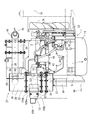
- FIG. 1 is a left side view in which an exhaust manifold of a diesel engine is installed
- FIG. 2 is a right side view in which an intake manifold of the diesel engine is installed
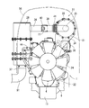
- FIG. 3 is a front view in which a cooling fan of the diesel engine is installed.
- the overall structure of the diesel engine 1 will be described with reference to FIGS.
- an intake manifold 3 is disposed on one side of the cylinder head 2 of the diesel engine 1.
- the cylinder head 2 is mounted on a cylinder block 5 in which an engine output shaft 4 (crankshaft) and a piston (not shown) are built.
- An exhaust manifold 6 is disposed on the other side of the cylinder head 2. The front end and the rear end of the engine output shaft 4 are projected from the front and rear surfaces of the cylinder block 5.
- a flywheel housing 8 is fixed to the rear surface of the cylinder block 5.
- a flywheel (not shown) is provided in the flywheel housing 8.
- the flywheel is pivotally supported on the rear end side of the engine output shaft 4.
- the power of the diesel engine 1 is taken out through the flywheel.
- an oil pan 11 is disposed on the lower surface of the cylinder block 5.
- an exhaust gas recirculation device (EGR) 15 that takes in exhaust gas for recirculation is disposed in the intake manifold 3.
- An air cleaner 16 shown in FIG. 4 is connected to the intake manifold 3. The external air that has been dedusted and purified by the air cleaner 16 is sent to the intake manifold 3 and supplied to each cylinder of the diesel engine 1.
- a cooling water pump 21 for circulating cooling water in the cylinder block 5 and the radiator 19 shown in FIG. 4 is provided.
- a cooling water pump 21 is disposed on the side of the diesel engine 1 where the cooling fan 24 is installed.
- the cooling water pump 21 and the cooling fan 24 are connected to the engine output shaft 4 via the V belt 22 and the like, and the cooling water pump 21 and the cooling fan 24 are driven. While the cooling water is sent from the cooling water pump 21 into the cylinder block 5 via the EGR cooler 18 of the exhaust gas recirculation device 15, the diesel engine 1 is cooled by the cooling fan 24 wind. .
- a first case 28 as a curate filter (DPF) and a second case 29 as a urea selective catalytic reduction (SCR) system for removing nitrogen oxides in exhaust gas of the diesel engine 1 are provided.
- DPF curate filter
- SCR selective catalytic reduction
- an oxidation catalyst 30 and a soot filter 31 are provided in the first case 28.
- the second case 29 includes an SCR catalyst 32 and an oxidation catalyst 33 for reducing urea selective catalyst.
- Exhaust gas discharged from each cylinder of the diesel engine 1 to the exhaust manifold 6 is discharged to the outside via the exhaust gas purification device 27 and the like.
- the exhaust gas purification device 27 is configured to reduce carbon monoxide (CO), hydrocarbons (HC), particulate matter (PM), and nitrogen oxides (NOx) in the exhaust gas of the diesel engine 1. is doing.
- the first case 28 is configured in a horizontally long elongated cylindrical shape extending long in a direction parallel to the output shaft (crankshaft) 4 of the diesel engine 1 in a plan view.
- a DPF inlet pipe 34 for taking in exhaust gas and a DPF outlet pipe 35 for discharging exhaust gas are provided on both sides of the first case 28 in the cylindrical shape (one end side and the other end side in the exhaust gas movement direction).
- the 2nd case 29 is comprised in the vertically long elongate cylindrical shape extended long in the up-down direction.
- an SCR inlet pipe 36 for taking in the exhaust gas and an SCR outlet pipe 37 for discharging the exhaust gas are provided on both sides of the second case 29 (one end side and the other end side in the exhaust gas movement direction).
- a supercharger 38 for forcibly sending air to the diesel engine 1 is arranged at the exhaust gas outlet of the exhaust manifold 6.
- the DPF inlet pipe 34 is communicated with the exhaust manifold 6 via the supercharger 38 to introduce the exhaust gas of the diesel engine 1 into the first case 28, while the SCR is connected to the DPF outlet pipe 35 via the urea mixing pipe 39.
- the inlet pipe 36 is connected, and the exhaust gas from the first case 28 is introduced into the second case 29.
- the DPF outlet pipe 35 and the urea mixing pipe 39 are connected to a bellows-like connecting pipe 41 that can be bent and stretched.
- the SCR inlet pipe 36 and the urea mixing pipe 39 are detachably fixed by a pipe bracket 40.
- a fuel pump 42 and a common rail 43 for connecting the fuel tank 45 shown in FIG. 4 are provided in each injector (not shown) for multiple cylinders of the diesel engine 1.
- a common rail 43 and a fuel filter 44 are disposed on the intake manifold 3 installation side of the cylinder head 2, and a fuel pump 42 is disposed on the cylinder block 5 below the intake manifold 3.
- Each injector has an electromagnetic switching control type fuel injection valve (not shown).
- the common rail 43 is connected to the discharge side of the fuel pump 42, and the cylindrical common rail 43 is connected to each injector of the diesel engine 1.
- the surplus of the fuel pumped from the fuel pump 42 to the common rail 43 is returned to the fuel tank 45, high-pressure fuel is temporarily stored in the common rail 43, and the high-pressure fuel in the common rail 43 is used for each diesel engine 1. Supplied inside the cylinder.
- the fuel in the fuel tank 45 is pumped to the common rail 43 by the fuel pump 42, the high-pressure fuel is stored in the common rail 43, and the fuel injection valves of the injectors are controlled to open and close.
- the high-pressure fuel in 43 is injected into each cylinder of the diesel engine 1. That is, by electronically controlling the fuel injection valve of each injector, the fuel injection pressure, injection timing, and injection period (injection amount) can be controlled with high accuracy. Therefore, nitrogen oxides (NOx) discharged from the diesel engine 1 can be reduced.
- FIG. 4 is a side view of the agricultural tractor
- FIG. 5 is a plan view thereof
- FIG. 6 is a left side view of the engine portion
- FIG. 7 is a right side view of the same portion
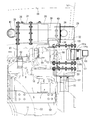
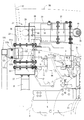
- FIG. 8 is a plan view of the same portion
- FIG. 8 is an enlarged plan view of FIG.
- the left side in the forward direction of the tractor is simply referred to as the left side
- the right side in the forward direction is also simply referred to as the right side.
- a farm tractor 51 as a work vehicle supports a traveling machine body 52 with a pair of left and right front wheels 53 and a pair of left and right rear wheels 54.
- the engine 1 is mounted, and the diesel engine 1 is configured to travel forward and backward by driving the rear wheel 54 and the front wheel 53.
- the upper surface side and the left and right side surfaces of the diesel engine 1 are covered with an openable / closable bonnet 56.
- a driving cabin 57 is installed as a driving unit on which an operator gets on.
- a steering seat 58 on which an operator is seated and steering equipment such as a steering handle 59 as steering means are provided.
- a pair of left and right steps 60 for the operator to get on and off are provided in the left and right outer portions of the cabin 57, and fuel is supplied to the diesel engine 1 inside the step 60 and below the bottom portion of the cabin 57.
- a fuel tank 45 to be supplied is provided.
- the traveling machine body 52 includes a transmission case 61 for shifting the output from the diesel engine 1 and transmitting it to the rear wheels 54 (front wheels 53).
- a tiller working machine (not shown) is connected to the rear portion of the mission case 61 via a lower link 62, a top link 63, a lift arm 64, and the like so as to be movable up and down.
- a PTO shaft 65 for driving the tilling work machine and the like is provided on the rear side surface of the mission case 61.
- the traveling machine body 52 of the tractor 51 includes the diesel engine 1, a transmission case 61, a clutch case 66 that connects them, and the like.
- the DPF inlet pipe 34 is detachably bolted to the exhaust gas outlet pipe 80 of the supercharger 38.
- the upper end side of the DPF support leg 81 is fastened and fixed to the outer peripheral surface of the end portion on the DPF outlet pipe 35 side of the outer peripheral surface of the first case 28, and on the side surface of the cylinder head 2 or the upper surface of the exhaust manifold 6.
- the bolt 82 is fastened to the lower end side of the DPF support leg 81 so as to be detachable. That is, the first case 28 is attached to the upper surface side of the diesel engine 1 through the exhaust gas outlet pipe 80 and the DPF support leg 81.
- the first case 28 is supported in parallel with the exhaust manifold 6 with the longitudinal direction of the cylindrical first case 28 facing the longitudinal direction of the diesel engine 1.
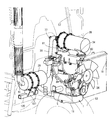
- the second case 29 is supported by the traveling machine frame 120 that forms the cabin 57.
- a pair of left and right purification case supports 121 are integrally fixed to the traveling machine body frame 120 by welding, and a pair of left and right purification case supports 121 are projected from the traveling machine body frame 120 toward the front.
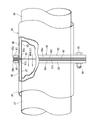
- the back support bracket 122 is integrally welded and fixed to the back side of the second case 29, and the second case 29 is directed rearward from the middle portion of the vertical width. The back support bracket 122 is projected.
- An upper bolt 126a and a lower bolt are fitted between the pair of left and right purification case supports 121 and screwed to the left and right sides of the pair of left and right purification case supports 121 and the rear support bracket 122 from the left and right directions.
- the back support bracket 122 is detachably fastened to the purification case support 121 by 126b.
- the upper bolt 126 a is removably locked to the engagement notch 121 a of the purification case support 121 and the lower bolt 126 b is inserted into the position adjusting long hole 121 b of the purification case support 121.
- the upper bolt 126 a is temporarily fixed to the back support bracket 122, the second case 29 is brought close to the mounting position of the purification case support 121, and the purification case support 121 is engaged.
- the upper bolt 126a is engaged with the notch 121a, and the second case 29 is temporarily fixedly supported by the purification case support 121.
- the lower bolt 126b is passed through the position adjusting long hole 121b of the purification case support 121, the lower bolt 126b is fastened to the back support bracket 122, and the upper bolt 126a is fastened to the back support bracket 122.
- the rear support bracket 122 is detachably fixed to the purification case support 121, and the second case 29 is mounted on the front side of the cabin 57 (operating unit) via the traveling machine body frame 120.
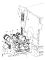
- the first case 28 is horizontally disposed in the front-rear direction (horizontal posture) on the upper surface side of the diesel engine 1, while the second case 29 is positioned in the vertically long posture on the right side of the rear portion of the diesel engine 1.
- a urea mixing tube 39 is arranged in parallel with the first case 28.
- the first case 28 and the urea mixing pipe 39 are supported at a position higher than the cooling air passage of the cooling fan 24 on the upper surface of the diesel engine 1.
- the temperature of the exhaust gas in the urea mixing pipe 39 is prevented from decreasing, and urea water supplied into the urea mixing pipe 39 is prevented from crystallizing.
- the urea water supplied into the urea mixing pipe 39 is configured to be mixed as ammonia in the exhaust gas from the first case 28 to the second case 29.
- a tail pipe 91 is erected on the front surface of the right corner of the cabin 57 of the front surface of the cabin 57, and the lower end side of the tail pipe 91 is directed toward the lower end side of the second case 29.
- the lower end side of the tail pipe 91 is connected to the SCR outlet pipe 37 on the lower end side of the second case 29, and the exhaust gas hatched in the second case 29 is discharged from the tail pipe 91 toward the upper side of the cabin 57. Is done.
- a urea water tank 71 is installed on the left side of the bonnet 56 on the opposite side of the front side of the cabin 57 from the right side where the tail pipe 91 is disposed. That is, the tail pipe 91 is disposed on the right side of the rear part of the bonnet 56, and the urea water tank 71 is disposed on the left side of the rear part of the bonnet 56.
- the urea water tank 71 is mounted on the traveling machine body 52 (the traveling machine body frame 120 on which the cabin 57 is supported) on the rear left side of the bonnet 56.
- An oil filling port 46 of the fuel tank 45 and a water filling port 72 of the urea water tank 71 are provided adjacent to each other at the lower front portion on the left side of the cabin 57.
- the tail pipe 91 is disposed on the front surface on the right side of the cabin 57 where the operator's boarding / alighting frequency is low, and the oil inlet 46 and the water inlet 72 are disposed on the front surface on the left side of the cabin 57 where the operator's boarding / alighting frequency is high.
- the cabin 57 is configured so that the operator can get on and off the control seat 58 from either the left side or the right side.
- a urea water injection pump 73 that pumps the urea aqueous solution in the urea water tank 71, an electric motor 74 that drives the urea water injection pump 73, and urea that is connected to the urea water injection pump 73 via a urea water injection pipe 75.
- a water injection nozzle 76 is provided.
- a urea water injection nozzle 76 is attached to the urea mixing pipe 39 via an injection base 77, and the urea aqueous solution is sprayed from the urea water injection nozzle 76 into the urea mixing pipe 39.
- the oxidation catalyst 30 and the soot filter 31 in the first case 28 reduce carbon monoxide (CO) and hydrocarbons (HC) in the exhaust gas of the diesel engine 1.
- urea water from the urea water injection nozzle 7 is mixed with the exhaust gas from the diesel engine 1 inside the urea mixing pipe 39.
- the SCR catalyst 32 and the oxidation catalyst 33 in the second case 29 reduce nitrogen oxides (NOx) in the exhaust gas mixed with urea water as ammonia, and are released from the tail pipe 91 to the outside of the machine. .
- the pipe bracket 40 that connects the SCR inlet pipe 36 and the urea mixing pipe 39 includes the inlet flange 92 disposed on the exhaust gas inlet side of the SCR inlet pipe 36, and the exhaust of the urea mixing pipe 39. It has an outlet side flange body 93 disposed on the gas outlet side.
- the outer pipe 86 and the inner pipe 87 of the SCR inlet pipe 36 of the double pipe structure are bent outward at the exhaust gas inlet side end portions, and ring-shaped sandwiching piece portions 86c, 87c at the exhaust gas inlet side end portions thereof.
- the exhaust gas outlet side end portions of the outer tube 88 and the inner tube 89 of the urea mixing tube 39 having a double-pipe structure are bent outward, and a ring is attached to the exhaust gas outlet side end portion thereof.
- Shaped clamping piece portions 88c and 89c are formed.
- the sandwiching piece portions 86c, 87c, 88c, 89c and the gasket 90 are sandwiched between the inlet side flange body 92 and the outlet side flange body 93, and the inlet side flange body 92 and the outlet side flange body 93 are connected with bolts 94 and nuts 95.
- the clamping piece portions 86c, 87c, 88c, 89c and the gasket 90 are clamped and fixed between the inlet side flange body 92 and the outlet side flange body 93, and the SCR inlet pipe 36 and the urea mixing pipe 39 are connected.
- the outer tube 86 of the SCR inlet tube 36 and the outer tube 88 of the urea mixing tube 39 are formed of the same diameter pipe, and the inner tube 87 of the SCR inlet tube 36 and the inner tube 89 of the urea mixing tube 39 are also formed. It is formed with pipes of the same diameter.
- the pipe thickness of each inner pipe 87, 89 is made thinner than the pipe thickness of each outer pipe 86, 88.
- the exhaust gas in the urea mixing pipe 39 is configured to move to the SCR inlet pipe 36 without contacting the inner hole surface of the inlet side flange body 92 or the outlet side flange body 93.
- the exhaust gas comes into contact with the inner hole surface of the inlet-side flange body 92 or the outlet-side flange body 93, the temperature of the exhaust gas decreases and the urea component in the exhaust gas crystallizes, and the inlet-side flange body 92 Or, it adheres to the inner hole surface of the outlet side flange body 93, and a crystal lump of urea component is formed on the inner hole surface of the inlet side flange body 92 or the outlet side flange body 93, thereby causing a problem that hinders the movement of exhaust gas.
- the inlet side flange body 92 or the outlet side flange body 93 is shielded by the sandwiching pieces 86 c, 87 c, 88 c, and 89 c so that the inlet side flange body 92 is shielded.
- the urea mixing pipe 39 includes an elbow pipe portion 39 a connected to the bellows-like connecting pipe 41 and a long cylindrical straight pipe connected to the SCR inlet pipe 36 via the pipe bracket 40. It has a part 39b.
- the injection base 77 is welded and fixed to the elbow pipe part 39a in the vicinity where the elbow pipe part 39a and the straight pipe part 39b are joined, and the urea water injection nozzle 76 is opened from the elbow pipe part 39a toward the inner hole of the straight pipe part 39b.
- the urea water injection direction 112 of the urea water injection nozzle 76 is set with respect to the cylindrical axis 111 of the cylindrical straight pipe portion 39b (the exhaust gas flow direction in the straight pipe portion 39b).
- the elbow pipe portion 39a is inclined to the exhaust gas lower side by a predetermined inclination angle 113 (about 2 to 20 degrees, for example, about 12 degrees, about 8 degrees, about 4 degrees, etc.). That is, urea water is injected from the urea water injection nozzle 76 toward the inner wall surface 114a on the curved inner diameter side of the elbow pipe portion 39a in the inner wall surface 114 of the straight pipe portion 39b.
- the urea water injected from the urea water injection nozzle 76 is out of the curvature of the elbow pipe portion 39a in the inner wall surface 114 of the straight pipe portion 39b due to the discharge pressure of the exhaust gas moving from the elbow pipe portion 39a to the straight pipe portion 39b. It diffuses toward the inner wall surface 114b on the radial side and is mixed as ammonia in the exhaust gas.
- the inclination angle 113 (urea water injection direction 112) of the urea water injection nozzle 76 with respect to the cylindrical axis 111 of the straight pipe portion 39b is the inner diameter of the elbow pipe portion 39a and the straight pipe portion 39b, or standard work (diesel engine 1).
- the operation is performed based on the exhaust gas flow velocity at the rated rotation of the engine). For example, when the inclination angle 113 is excessive, urea water adheres to the inner wall surface 114a on the curved inner diameter side of the elbow pipe portion 39a, and urea tends to crystallize on the inner wall surface 114a on the curved inner diameter side.
- a first case 28 for removing particulate matter in the exhaust gas of the diesel engine 1 and a second case 29 for removing nitrogen oxides in the exhaust gas of the diesel engine 1 are provided.
- the first case 28 is supported on the diesel engine 1 (or the traveling machine body frame 120).
- the second case 29 is attached to the traveling machine body frame 120 via the support body 121.
- the bonnet 56 engine room in which the diesel engine 1 is installed can be configured compactly, and the traveling machine body frame 120 can be configured.
- the second case 29 can be easily supported, and the assembling workability or maintenance workability of the cases 28 and 29 formed in a long cylindrical shape can be improved.
- the exhaust gas outlet of the first case 28 and the exhaust gas inlet of the second case 29 are spaced at intervals necessary for mixing urea. It can be separated and the generation of ammonia in the exhaust gas reaching the second case 29 can be promoted.
- the first case 28 is supported by the diesel engine 1, but it goes without saying that the first case 28 may be supported by the traveling machine body frame 120.
- the second case 29 is attached to the traveling body frame 120 on one side of the rear portion of the diesel engine 1 in a vertically long posture via a purification case support 121. Therefore, the second case 29 formed in a cylindrical shape with a long outer shape can be installed compactly near the rear part of the diesel engine 1 (near the joint corner of the hood 56 and the cabin 57 as the operating part). For example, even in a structure in which the left and right widths of the bonnet 56 are limited so that the front wheels can be visually observed, the operator's front view from the cabin 57 (operating unit) can be easily secured.
- a work vehicle is provided with a cabin 57 as a driving unit on which an operator gets on behind a bonnet 56 in which the diesel engine 1 is installed, and a fuel provided in a lower portion of the cabin 57.
- a urea water tank 71 for purifying exhaust gas is installed between the tank 45 and the diesel engine 1, a second case 29 is disposed on one side of the rear part of the diesel engine 1, and urea is disposed on the other side of the rear part of the diesel engine 1.
- a water tank 71 is arranged.
- the fuel filling port 46 (fuel filling port) of the fuel tank 45 and the water filling port 72 (water filling port) of the urea water tank 71 can be arranged close to each other, and the fuel supply work and the urea aqueous solution water supply work are executed at the same work place.
- the installation space for the second case 29 and the urea water tank 71 both sides of the rear part of the diesel engine 1 ( The front lower part of the cabin 57 can be used effectively.
- the urea water tank 71 can be heated by the exhaust heat of the diesel engine 1 and the fuel tank 45, the aqueous solution temperature in the urea water tank 71 can be maintained at a predetermined level or more, and the exhaust gas of the second case 29 in a cold district or the like. It is possible to prevent the purification capacity from being lowered.
- the first case 28 is attached to the upper surface side of the diesel engine 1 via the DPF support leg 81, and the intake manifold 3, the exhaust gas recirculation device 15,
- the second case 29 is detachably fastened to the purification case support 121 of the traveling machine body frame 120 on the side where the fuel filter 44 and the like are installed. That is, the second case 29 is configured in a horizontally long elongated cylindrical shape that extends long in the left-right direction.
- the second case 29 is attached to the traveling body frame 120 at the lower right side of the rear portion of the diesel engine 1 in a horizontally long posture, and the second case 29 in a horizontally long posture is disposed between the right front surface of the cabin 57 and the right front wheel 53, and the diesel engine.
- a urea mixing tube 39 is extended to the rear, a urea mixing tube 39 is connected to the left end side of the second case 29, and a tail pipe 91 is connected to the right end side of the second case 29.
- the second case 29 is attached to the traveling body frame 120 on one side of the rear portion of the diesel engine 1 through the purification case support 121 in a horizontally long posture.
- the outer case is formed in a long cylindrical shape, and the second case 29 can be installed compactly.
- the second case 29 is easily disposed at a lower position on the front side of the cabin 57 in the right outside of the rear part of the bonnet 56.
- the operator's front view from the cabin 57 can be easily secured.
- the exhaust gas movement direction (cylindrical axis) of the first case 28 and the second case 29 is set with respect to the output shaft 4 of the diesel engine 1 extending in the front-rear direction.
- the first case 28 and the second case 29 are extended in the left-right direction so as to be orthogonal to each other.
- the first case 28 and the second case 29 are arranged in parallel on the upper surface side of the cooling fan 24 installation portion of the upper surface side of the diesel engine 1, and the urea mixing tube 39 is interposed between the first case 28 and the second case 29. It extends in parallel.
- the first case 28 and the second case 29 are arranged at a higher position than the cooling fan 24 air passage of the diesel engine 1.
- the first case 28 and the second case 29 of the fourth embodiment are arranged on the traveling machine body 52 on which the air cleaner 16 is installed.
- the first case 28 and the second case 29 are supported by the traveling machine body 52 ahead of the radiator 19.
- the first case 28 and the second case 29 are formed in a long cylindrical shape extending long in a direction parallel to the output shaft (crankshaft) 4 of the diesel engine 1 in plan view.
- a urea mixing tube 39 is disposed between the first case 28 and the second case 29 in parallel therewith.
- the second case 29 can be attached close to the traveling machine body 52, and the bonnet height required for installing the first case 28 and the second case 29 can be formed low.
Landscapes
- Engineering & Computer Science (AREA)
- Chemical & Material Sciences (AREA)
- General Engineering & Computer Science (AREA)
- Combustion & Propulsion (AREA)
- Mechanical Engineering (AREA)
- Chemical Kinetics & Catalysis (AREA)
- Health & Medical Sciences (AREA)
- Toxicology (AREA)
- Structural Engineering (AREA)
- Civil Engineering (AREA)
- Mining & Mineral Resources (AREA)
- Transportation (AREA)
- Exhaust Gas After Treatment (AREA)
- Component Parts Of Construction Machinery (AREA)
Abstract
Description
28 第1ケース
29 第2ケース
45 燃料タンク
53 前車輪(走行輪)
54 後車輪(走行輪)
56 ボンネット
57 キャビン(運転部)
71 尿素水タンク
120 走行機体フレーム
121 浄化ケース支持体
Claims (4)
- エンジンの排気ガス中の粒子状物質を除去する第1ケースと、前記エンジンの排気ガス中の窒素酸化物質を除去する第2ケースを備え、左右の走行輪が配置される走行機体フレームに前記エンジンを搭載する作業車両のエンジン装置において、
前記エンジンまたは前記走行機体フレームのいずれか一方に前記第1ケースを支持する構造であって、前記走行機体フレームに支持体を介して前記第2ケースを取付けたことを特徴とする作業車両のエンジン装置。 - 前記エンジン後部の一側方の前記走行機体フレームに支持体を介して前記第2ケースを縦長姿勢に取付けたことを特徴とする請求項1に記載の作業車両のエンジン装置。
- 前記エンジン後部の一側方の前記走行機体フレームに支持体を介して前記第2ケースを横長姿勢に取付けたことを特徴とする請求項1に記載の作業車両のエンジン装置。
- 前記エンジンが内設されたボンネットの後方に、オペレータが搭乗する運転部を配置した作業車両であって、前記運転部の下部に設けた燃料タンクと前記エンジンの間に排気ガス浄化用の尿素水タンクを設置すると共に、前記エンジン後部の一側方に前記第2ケースを配置し、前記エンジン後部の他側方に前記尿素水タンクを配置したことを特徴とする請求項1に記載の作業車両のエンジン装置。
Priority Applications (8)
| Application Number | Priority Date | Filing Date | Title |
|---|---|---|---|
| KR1020217007182A KR20210030499A (ko) | 2013-03-28 | 2014-03-26 | 작업 차량의 엔진 장치 |
| KR1020257019032A KR20250088788A (ko) | 2013-03-28 | 2014-03-26 | 작업 차량의 엔진 장치 |
| EP14775262.0A EP2980381B1 (en) | 2013-03-28 | 2014-03-26 | Engine device for work vehicles |
| KR1020227001825A KR102608485B1 (ko) | 2013-03-28 | 2014-03-26 | 작업 차량의 엔진 장치 |
| KR1020157023803A KR102228359B1 (ko) | 2013-03-28 | 2014-03-26 | 작업 차량의 엔진 장치 |
| US14/776,201 US9534523B2 (en) | 2013-03-28 | 2014-03-26 | Engine device for work vehicle |
| CN201480018088.8A CN105074154B (zh) | 2013-03-28 | 2014-03-26 | 作业车辆的发动机装置 |
| KR1020237041086A KR20230167152A (ko) | 2013-03-28 | 2014-03-26 | 작업 차량의 엔진 장치 |
Applications Claiming Priority (2)
| Application Number | Priority Date | Filing Date | Title |
|---|---|---|---|
| JP2013069408A JP5956373B2 (ja) | 2013-03-28 | 2013-03-28 | 作業車両のエンジン装置 |
| JP2013-069408 | 2013-03-28 |
Publications (1)
| Publication Number | Publication Date |
|---|---|
| WO2014157285A1 true WO2014157285A1 (ja) | 2014-10-02 |
Family
ID=51624250
Family Applications (1)
| Application Number | Title | Priority Date | Filing Date |
|---|---|---|---|
| PCT/JP2014/058430 Ceased WO2014157285A1 (ja) | 2013-03-28 | 2014-03-26 | 作業車両のエンジン装置 |
Country Status (6)
| Country | Link |
|---|---|
| US (1) | US9534523B2 (ja) |
| EP (1) | EP2980381B1 (ja) |
| JP (1) | JP5956373B2 (ja) |
| KR (5) | KR20230167152A (ja) |
| CN (1) | CN105074154B (ja) |
| WO (1) | WO2014157285A1 (ja) |
Cited By (2)
| Publication number | Priority date | Publication date | Assignee | Title |
|---|---|---|---|---|
| JP2015163512A (ja) * | 2015-06-19 | 2015-09-10 | 株式会社クボタ | 作業車両 |
| US20160303511A1 (en) * | 2015-04-20 | 2016-10-20 | Iseki & Co., Ltd. | Tractor |
Families Citing this family (18)
| Publication number | Priority date | Publication date | Assignee | Title |
|---|---|---|---|---|
| JP6066787B2 (ja) * | 2013-03-15 | 2017-01-25 | ヤンマー株式会社 | コンバインのエンジン装置 |
| JP6343119B2 (ja) * | 2013-03-15 | 2018-06-13 | ヤンマー株式会社 | コンバインのエンジン装置 |
| JP6297905B2 (ja) * | 2014-04-22 | 2018-03-20 | 日立建機株式会社 | 建設機械 |
| CN208724407U (zh) * | 2015-12-22 | 2019-04-12 | 株式会社久保田 | 收割机 |
| WO2017110530A1 (ja) * | 2015-12-22 | 2017-06-29 | 株式会社クボタ | 収穫機 |
| EP3418521B1 (en) | 2016-02-19 | 2021-04-21 | Yanmar Power Technology Co., Ltd. | Engine device |
| JP6518616B2 (ja) * | 2016-03-29 | 2019-05-22 | 株式会社Kcm | 作業車両 |
| JP6815255B2 (ja) * | 2017-03-30 | 2021-01-20 | ヤンマーパワーテクノロジー株式会社 | トラクタ |
| CN108678844B (zh) * | 2018-07-13 | 2024-05-17 | 三江瓦力特特种车辆有限公司 | 用于石油修井机的发动机scr后处理系统 |
| JP6984691B2 (ja) * | 2018-12-18 | 2021-12-22 | 井関農機株式会社 | トラクタ |
| JP7243792B2 (ja) * | 2018-12-18 | 2023-03-22 | 井関農機株式会社 | トラクタ |
| JP2020059502A (ja) * | 2019-12-17 | 2020-04-16 | ヤンマー株式会社 | トラクタ |
| JP7143365B2 (ja) * | 2020-05-20 | 2022-09-28 | ヤンマーパワーテクノロジー株式会社 | トラクタ |
| JP7055854B2 (ja) * | 2020-10-29 | 2022-04-18 | ヤンマーパワーテクノロジー株式会社 | トラクタ |
| JP7557350B2 (ja) | 2020-11-19 | 2024-09-27 | ヤンマーホールディングス株式会社 | ディーゼルエンジン |
| JP7152464B2 (ja) | 2020-12-08 | 2022-10-12 | ヤンマーパワーテクノロジー株式会社 | トラクタ |
| KR102667665B1 (ko) | 2021-12-28 | 2024-05-21 | 한화토탈에너지스 주식회사 | 폴리에틸렌 수지 조성물 및 이로부터 제조되는 성형품 |
| JP2024140228A (ja) * | 2023-03-28 | 2024-10-10 | ヤンマーホールディングス株式会社 | 作業車両 |
Citations (8)
| Publication number | Priority date | Publication date | Assignee | Title |
|---|---|---|---|---|
| JP2009074420A (ja) | 2007-09-20 | 2009-04-09 | Hino Motors Ltd | 排気浄化装置 |
| WO2011129030A1 (ja) * | 2010-04-15 | 2011-10-20 | Udトラックス株式会社 | 排気浄化装置 |
| WO2011152306A1 (ja) * | 2010-05-31 | 2011-12-08 | 株式会社小松製作所 | 作業車両 |
| JP2012021505A (ja) | 2010-07-16 | 2012-02-02 | Isuzu Motors Ltd | 排気ガス浄化装置 |
| JP2012126209A (ja) * | 2010-12-14 | 2012-07-05 | Yanmar Co Ltd | 作業車両 |
| JP2012177233A (ja) | 2011-02-25 | 2012-09-13 | Hitachi Constr Mach Co Ltd | 建設機械 |
| JP2012219624A (ja) * | 2011-04-04 | 2012-11-12 | Hitachi Constr Mach Co Ltd | 建設機械 |
| WO2013003716A2 (en) * | 2011-06-30 | 2013-01-03 | Caterpillar Inc. | Def pump mounted to tank |
Family Cites Families (14)
| Publication number | Priority date | Publication date | Assignee | Title |
|---|---|---|---|---|
| JP4462556B2 (ja) | 2005-08-04 | 2010-05-12 | 三菱ふそうトラック・バス株式会社 | 内燃機関の排気浄化装置 |
| US7717205B2 (en) * | 2006-11-28 | 2010-05-18 | Caterpillar Inc. | Engine hood assembly enclosure with exhaust aftertreatment device integrated therein, and machine using same |
| JP4900163B2 (ja) * | 2007-09-26 | 2012-03-21 | コベルコ建機株式会社 | 建設機械 |
| JP5101324B2 (ja) * | 2008-02-07 | 2012-12-19 | 日立建機株式会社 | 建設機械のNOx低減装置の配設構造 |
| JP5224954B2 (ja) * | 2008-07-17 | 2013-07-03 | ヤンマー株式会社 | コンバイン |
| JP2010063417A (ja) * | 2008-09-11 | 2010-03-25 | Yanmar Co Ltd | コンバイン |
| GB2465151A (en) | 2008-11-05 | 2010-05-12 | Agco Sa | Engine exhaust treatment unit |
| GB2466483A (en) | 2008-12-19 | 2010-06-30 | Agco Gmbh & Co | A vertical exhaust system for a vehicle |
| GB0913581D0 (en) | 2009-08-05 | 2009-09-16 | Agco Gmbh | Tractors |
| JP5402451B2 (ja) * | 2009-09-17 | 2014-01-29 | コベルコ建機株式会社 | 建設機械 |
| JP2011127472A (ja) * | 2009-12-16 | 2011-06-30 | Iseki & Co Ltd | ディーゼルエンジン |
| JP2011156948A (ja) * | 2010-01-29 | 2011-08-18 | Iseki & Co Ltd | 作業車両 |
| US20120042637A1 (en) | 2010-08-18 | 2012-02-23 | Caterpillar Inc. | Tall vertical scr |
| WO2012117753A1 (ja) * | 2011-02-28 | 2012-09-07 | 株式会社小松製作所 | 建設車両 |
-
2013
- 2013-03-28 JP JP2013069408A patent/JP5956373B2/ja active Active
-
2014
- 2014-03-26 KR KR1020237041086A patent/KR20230167152A/ko not_active Ceased
- 2014-03-26 US US14/776,201 patent/US9534523B2/en active Active
- 2014-03-26 KR KR1020217007182A patent/KR20210030499A/ko not_active Ceased
- 2014-03-26 CN CN201480018088.8A patent/CN105074154B/zh active Active
- 2014-03-26 KR KR1020227001825A patent/KR102608485B1/ko active Active
- 2014-03-26 EP EP14775262.0A patent/EP2980381B1/en active Active
- 2014-03-26 KR KR1020257019032A patent/KR20250088788A/ko active Pending
- 2014-03-26 KR KR1020157023803A patent/KR102228359B1/ko active Active
- 2014-03-26 WO PCT/JP2014/058430 patent/WO2014157285A1/ja not_active Ceased
Patent Citations (8)
| Publication number | Priority date | Publication date | Assignee | Title |
|---|---|---|---|---|
| JP2009074420A (ja) | 2007-09-20 | 2009-04-09 | Hino Motors Ltd | 排気浄化装置 |
| WO2011129030A1 (ja) * | 2010-04-15 | 2011-10-20 | Udトラックス株式会社 | 排気浄化装置 |
| WO2011152306A1 (ja) * | 2010-05-31 | 2011-12-08 | 株式会社小松製作所 | 作業車両 |
| JP2012021505A (ja) | 2010-07-16 | 2012-02-02 | Isuzu Motors Ltd | 排気ガス浄化装置 |
| JP2012126209A (ja) * | 2010-12-14 | 2012-07-05 | Yanmar Co Ltd | 作業車両 |
| JP2012177233A (ja) | 2011-02-25 | 2012-09-13 | Hitachi Constr Mach Co Ltd | 建設機械 |
| JP2012219624A (ja) * | 2011-04-04 | 2012-11-12 | Hitachi Constr Mach Co Ltd | 建設機械 |
| WO2013003716A2 (en) * | 2011-06-30 | 2013-01-03 | Caterpillar Inc. | Def pump mounted to tank |
Non-Patent Citations (1)
| Title |
|---|
| See also references of EP2980381A4 |
Cited By (4)
| Publication number | Priority date | Publication date | Assignee | Title |
|---|---|---|---|---|
| US20160303511A1 (en) * | 2015-04-20 | 2016-10-20 | Iseki & Co., Ltd. | Tractor |
| US9943805B2 (en) * | 2015-04-20 | 2018-04-17 | Iseki & Co., Ltd. | Tractor |
| JP2015163512A (ja) * | 2015-06-19 | 2015-09-10 | 株式会社クボタ | 作業車両 |
| EP3109085A1 (en) * | 2015-06-19 | 2016-12-28 | Kubota Corporation | Work vehicle |
Also Published As
| Publication number | Publication date |
|---|---|
| KR20250088788A (ko) | 2025-06-17 |
| KR102228359B1 (ko) | 2021-03-15 |
| JP5956373B2 (ja) | 2016-07-27 |
| CN105074154A (zh) | 2015-11-18 |
| KR102608485B1 (ko) | 2023-11-30 |
| KR20150135251A (ko) | 2015-12-02 |
| KR20230167152A (ko) | 2023-12-07 |
| JP2014190321A (ja) | 2014-10-06 |
| CN105074154B (zh) | 2018-01-30 |
| EP2980381A1 (en) | 2016-02-03 |
| US9534523B2 (en) | 2017-01-03 |
| EP2980381B1 (en) | 2017-09-13 |
| KR20220013458A (ko) | 2022-02-04 |
| US20160040568A1 (en) | 2016-02-11 |
| EP2980381A4 (en) | 2016-12-07 |
| KR20210030499A (ko) | 2021-03-17 |
Similar Documents
| Publication | Publication Date | Title |
|---|---|---|
| JP5956373B2 (ja) | 作業車両のエンジン装置 | |
| JP5918154B2 (ja) | 作業車両のエンジン装置 | |
| WO2014157286A1 (ja) | エンジン装置 | |
| JP6200682B2 (ja) | トラクタ | |
| WO2014175168A1 (ja) | 作業車両 | |
| WO2015093375A1 (ja) | 作業車両 | |
| JP5955243B2 (ja) | エンジン装置 | |
| JP6284281B2 (ja) | トラクタ | |
| JP5876851B2 (ja) | エンジン装置 | |
| JP6091288B2 (ja) | エンジン装置 | |
| JP6157966B2 (ja) | トラクタ | |
| JP6216413B2 (ja) | トラクタ | |
| JP6280536B2 (ja) | トラクタ | |
| JP6177005B2 (ja) | 作業車両 | |
| JP2014190328A (ja) | エンジン装置 | |
| JP2014190330A (ja) | エンジン装置 | |
| JP6162519B2 (ja) | トラクタ | |
| JP2015117597A (ja) | 作業車両 | |
| JP2016065542A (ja) | 作業車両 | |
| JP2017008947A (ja) | 作業車両 | |
| JP6151629B2 (ja) | 作業車両 | |
| JP2015020714A (ja) | 作業車両 |
Legal Events
| Date | Code | Title | Description |
|---|---|---|---|
| WWE | Wipo information: entry into national phase |
Ref document number: 201480018088.8 Country of ref document: CN |
|
| 121 | Ep: the epo has been informed by wipo that ep was designated in this application |
Ref document number: 14775262 Country of ref document: EP Kind code of ref document: A1 |
|
| ENP | Entry into the national phase |
Ref document number: 20157023803 Country of ref document: KR Kind code of ref document: A |
|
| WWE | Wipo information: entry into national phase |
Ref document number: 14776201 Country of ref document: US |
|
| NENP | Non-entry into the national phase |
Ref country code: DE |
|
| REEP | Request for entry into the european phase |
Ref document number: 2014775262 Country of ref document: EP |
|
| WWE | Wipo information: entry into national phase |
Ref document number: 2014775262 Country of ref document: EP |
|
| WWR | Wipo information: refused in national office |
Ref document number: 1020237041086 Country of ref document: KR |
|
| WWD | Wipo information: divisional of initial pct application |
Ref document number: 1020257019032 Country of ref document: KR |
|
| WWP | Wipo information: published in national office |
Ref document number: 1020257019032 Country of ref document: KR |