WO2014157419A1 - 非水電解質二次電池 - Google Patents
非水電解質二次電池 Download PDFInfo
- Publication number
- WO2014157419A1 WO2014157419A1 PCT/JP2014/058687 JP2014058687W WO2014157419A1 WO 2014157419 A1 WO2014157419 A1 WO 2014157419A1 JP 2014058687 W JP2014058687 W JP 2014058687W WO 2014157419 A1 WO2014157419 A1 WO 2014157419A1
- Authority
- WO
- WIPO (PCT)
- Prior art keywords
- active material
- material layer
- negative electrode
- electrode active
- secondary battery
- Prior art date
- Legal status (The legal status is an assumption and is not a legal conclusion. Google has not performed a legal analysis and makes no representation as to the accuracy of the status listed.)
- Ceased
Links
Images

Classifications
-
- H—ELECTRICITY
- H01—ELECTRIC ELEMENTS
- H01M—PROCESSES OR MEANS, e.g. BATTERIES, FOR THE DIRECT CONVERSION OF CHEMICAL ENERGY INTO ELECTRICAL ENERGY
- H01M4/00—Electrodes
- H01M4/02—Electrodes composed of, or comprising, active material
- H01M4/62—Selection of inactive substances as ingredients for active masses, e.g. binders, fillers
- H01M4/621—Binders
-
- H—ELECTRICITY
- H01—ELECTRIC ELEMENTS
- H01M—PROCESSES OR MEANS, e.g. BATTERIES, FOR THE DIRECT CONVERSION OF CHEMICAL ENERGY INTO ELECTRICAL ENERGY
- H01M4/00—Electrodes
- H01M4/02—Electrodes composed of, or comprising, active material
- H01M4/62—Selection of inactive substances as ingredients for active masses, e.g. binders, fillers
- H01M4/621—Binders
- H01M4/622—Binders being polymers
-
- H—ELECTRICITY
- H01—ELECTRIC ELEMENTS
- H01M—PROCESSES OR MEANS, e.g. BATTERIES, FOR THE DIRECT CONVERSION OF CHEMICAL ENERGY INTO ELECTRICAL ENERGY
- H01M10/00—Secondary cells; Manufacture thereof
- H01M10/04—Construction or manufacture in general
- H01M10/0481—Compression means other than compression means for stacks of electrodes and separators
-
- H—ELECTRICITY
- H01—ELECTRIC ELEMENTS
- H01M—PROCESSES OR MEANS, e.g. BATTERIES, FOR THE DIRECT CONVERSION OF CHEMICAL ENERGY INTO ELECTRICAL ENERGY
- H01M10/00—Secondary cells; Manufacture thereof
- H01M10/05—Accumulators with non-aqueous electrolyte
- H01M10/052—Li-accumulators
-
- H—ELECTRICITY
- H01—ELECTRIC ELEMENTS
- H01M—PROCESSES OR MEANS, e.g. BATTERIES, FOR THE DIRECT CONVERSION OF CHEMICAL ENERGY INTO ELECTRICAL ENERGY
- H01M10/00—Secondary cells; Manufacture thereof
- H01M10/05—Accumulators with non-aqueous electrolyte
- H01M10/056—Accumulators with non-aqueous electrolyte characterised by the materials used as electrolytes, e.g. mixed inorganic/organic electrolytes
- H01M10/0561—Accumulators with non-aqueous electrolyte characterised by the materials used as electrolytes, e.g. mixed inorganic/organic electrolytes the electrolyte being constituted of inorganic materials only
- H01M10/0562—Solid materials
-
- H—ELECTRICITY
- H01—ELECTRIC ELEMENTS
- H01M—PROCESSES OR MEANS, e.g. BATTERIES, FOR THE DIRECT CONVERSION OF CHEMICAL ENERGY INTO ELECTRICAL ENERGY
- H01M4/00—Electrodes
- H01M4/02—Electrodes composed of, or comprising, active material
- H01M4/13—Electrodes for accumulators with non-aqueous electrolyte, e.g. for lithium-accumulators; Processes of manufacture thereof
-
- H—ELECTRICITY
- H01—ELECTRIC ELEMENTS
- H01M—PROCESSES OR MEANS, e.g. BATTERIES, FOR THE DIRECT CONVERSION OF CHEMICAL ENERGY INTO ELECTRICAL ENERGY
- H01M4/00—Electrodes
- H01M4/02—Electrodes composed of, or comprising, active material
- H01M4/13—Electrodes for accumulators with non-aqueous electrolyte, e.g. for lithium-accumulators; Processes of manufacture thereof
- H01M4/133—Electrodes based on carbonaceous material, e.g. graphite-intercalation compounds or CFx
-
- H—ELECTRICITY
- H01—ELECTRIC ELEMENTS
- H01M—PROCESSES OR MEANS, e.g. BATTERIES, FOR THE DIRECT CONVERSION OF CHEMICAL ENERGY INTO ELECTRICAL ENERGY
- H01M4/00—Electrodes
- H01M4/02—Electrodes composed of, or comprising, active material
- H01M4/36—Selection of substances as active materials, active masses, active liquids
- H01M4/38—Selection of substances as active materials, active masses, active liquids of elements or alloys
-
- H—ELECTRICITY
- H01—ELECTRIC ELEMENTS
- H01M—PROCESSES OR MEANS, e.g. BATTERIES, FOR THE DIRECT CONVERSION OF CHEMICAL ENERGY INTO ELECTRICAL ENERGY
- H01M50/00—Constructional details or processes of manufacture of the non-active parts of electrochemical cells other than fuel cells, e.g. hybrid cells
- H01M50/10—Primary casings; Jackets or wrappings
- H01M50/116—Primary casings; Jackets or wrappings characterised by the material
- H01M50/117—Inorganic material
- H01M50/119—Metals
-
- H—ELECTRICITY
- H01—ELECTRIC ELEMENTS
- H01M—PROCESSES OR MEANS, e.g. BATTERIES, FOR THE DIRECT CONVERSION OF CHEMICAL ENERGY INTO ELECTRICAL ENERGY
- H01M50/00—Constructional details or processes of manufacture of the non-active parts of electrochemical cells other than fuel cells, e.g. hybrid cells
- H01M50/10—Primary casings; Jackets or wrappings
- H01M50/116—Primary casings; Jackets or wrappings characterised by the material
- H01M50/124—Primary casings; Jackets or wrappings characterised by the material having a layered structure
-
- H—ELECTRICITY
- H01—ELECTRIC ELEMENTS
- H01M—PROCESSES OR MEANS, e.g. BATTERIES, FOR THE DIRECT CONVERSION OF CHEMICAL ENERGY INTO ELECTRICAL ENERGY
- H01M50/00—Constructional details or processes of manufacture of the non-active parts of electrochemical cells other than fuel cells, e.g. hybrid cells
- H01M50/40—Separators; Membranes; Diaphragms; Spacing elements inside cells
- H01M50/489—Separators, membranes, diaphragms or spacing elements inside the cells, characterised by their physical properties, e.g. swelling degree, hydrophilicity or shut down properties
-
- H—ELECTRICITY
- H01—ELECTRIC ELEMENTS
- H01M—PROCESSES OR MEANS, e.g. BATTERIES, FOR THE DIRECT CONVERSION OF CHEMICAL ENERGY INTO ELECTRICAL ENERGY
- H01M4/00—Electrodes
- H01M4/02—Electrodes composed of, or comprising, active material
- H01M2004/021—Physical characteristics, e.g. porosity, surface area
-
- H—ELECTRICITY
- H01—ELECTRIC ELEMENTS
- H01M—PROCESSES OR MEANS, e.g. BATTERIES, FOR THE DIRECT CONVERSION OF CHEMICAL ENERGY INTO ELECTRICAL ENERGY
- H01M2220/00—Batteries for particular applications
- H01M2220/20—Batteries in motive systems, e.g. vehicle, ship, plane
-
- H—ELECTRICITY
- H01—ELECTRIC ELEMENTS
- H01M—PROCESSES OR MEANS, e.g. BATTERIES, FOR THE DIRECT CONVERSION OF CHEMICAL ENERGY INTO ELECTRICAL ENERGY
- H01M50/00—Constructional details or processes of manufacture of the non-active parts of electrochemical cells other than fuel cells, e.g. hybrid cells
- H01M50/10—Primary casings; Jackets or wrappings
- H01M50/116—Primary casings; Jackets or wrappings characterised by the material
- H01M50/121—Organic material
-
- H—ELECTRICITY
- H01—ELECTRIC ELEMENTS
- H01M—PROCESSES OR MEANS, e.g. BATTERIES, FOR THE DIRECT CONVERSION OF CHEMICAL ENERGY INTO ELECTRICAL ENERGY
- H01M50/00—Constructional details or processes of manufacture of the non-active parts of electrochemical cells other than fuel cells, e.g. hybrid cells
- H01M50/10—Primary casings; Jackets or wrappings
- H01M50/116—Primary casings; Jackets or wrappings characterised by the material
- H01M50/124—Primary casings; Jackets or wrappings characterised by the material having a layered structure
- H01M50/126—Primary casings; Jackets or wrappings characterised by the material having a layered structure comprising three or more layers
- H01M50/129—Primary casings; Jackets or wrappings characterised by the material having a layered structure comprising three or more layers with two or more layers of only organic material
-
- Y—GENERAL TAGGING OF NEW TECHNOLOGICAL DEVELOPMENTS; GENERAL TAGGING OF CROSS-SECTIONAL TECHNOLOGIES SPANNING OVER SEVERAL SECTIONS OF THE IPC; TECHNICAL SUBJECTS COVERED BY FORMER USPC CROSS-REFERENCE ART COLLECTIONS [XRACs] AND DIGESTS
- Y02—TECHNOLOGIES OR APPLICATIONS FOR MITIGATION OR ADAPTATION AGAINST CLIMATE CHANGE
- Y02E—REDUCTION OF GREENHOUSE GAS [GHG] EMISSIONS, RELATED TO ENERGY GENERATION, TRANSMISSION OR DISTRIBUTION
- Y02E60/00—Enabling technologies; Technologies with a potential or indirect contribution to GHG emissions mitigation
- Y02E60/10—Energy storage using batteries
-
- Y—GENERAL TAGGING OF NEW TECHNOLOGICAL DEVELOPMENTS; GENERAL TAGGING OF CROSS-SECTIONAL TECHNOLOGIES SPANNING OVER SEVERAL SECTIONS OF THE IPC; TECHNICAL SUBJECTS COVERED BY FORMER USPC CROSS-REFERENCE ART COLLECTIONS [XRACs] AND DIGESTS
- Y02—TECHNOLOGIES OR APPLICATIONS FOR MITIGATION OR ADAPTATION AGAINST CLIMATE CHANGE
- Y02P—CLIMATE CHANGE MITIGATION TECHNOLOGIES IN THE PRODUCTION OR PROCESSING OF GOODS
- Y02P70/00—Climate change mitigation technologies in the production process for final industrial or consumer products
- Y02P70/50—Manufacturing or production processes characterised by the final manufactured product
-
- Y—GENERAL TAGGING OF NEW TECHNOLOGICAL DEVELOPMENTS; GENERAL TAGGING OF CROSS-SECTIONAL TECHNOLOGIES SPANNING OVER SEVERAL SECTIONS OF THE IPC; TECHNICAL SUBJECTS COVERED BY FORMER USPC CROSS-REFERENCE ART COLLECTIONS [XRACs] AND DIGESTS
- Y02—TECHNOLOGIES OR APPLICATIONS FOR MITIGATION OR ADAPTATION AGAINST CLIMATE CHANGE
- Y02T—CLIMATE CHANGE MITIGATION TECHNOLOGIES RELATED TO TRANSPORTATION
- Y02T10/00—Road transport of goods or passengers
- Y02T10/60—Other road transportation technologies with climate change mitigation effect
- Y02T10/70—Energy storage systems for electromobility, e.g. batteries
Definitions
- the present invention relates to a non-aqueous electrolyte secondary battery.
- a secondary battery that can be repeatedly charged and discharged is suitable as a power source for driving these motors, and a non-aqueous electrolyte secondary battery such as a lithium ion secondary battery that can be expected to have a high capacity and a high output is attracting attention.
- the nonaqueous electrolyte secondary battery has a positive electrode active material layer containing a positive electrode active material (for example, LiCoO 2 , LiMnO 2 , LiNiO 2, etc.) formed on the surface of the current collector.
- a positive electrode active material for example, LiCoO 2 , LiMnO 2 , LiNiO 2, etc.
- the non-aqueous electrolyte secondary battery includes a negative electrode active material formed on the current collector surface (for example, carbonaceous materials such as metallic lithium, coke and natural / artificial graphite, metals such as Sn and Si, and oxide materials thereof) Etc.).
- the binder for binding the active material used in the active material layer is an organic solvent binder (a binder that does not dissolve / disperse in water but dissolves / disperses in an organic solvent) and an aqueous binder (a binder that dissolves / disperses in water). )are categorized.
- the organic solvent-based binder requires a large amount of cost for materials, recovery, and disposal of the organic solvent, which may be industrially disadvantageous.
- water-based binders make it easy to procure water as a raw material, and since steam is generated during drying, capital investment in the production line can be greatly suppressed, and the environmental burden is reduced. There is an advantage that you can. Further, the water-based binder has an advantage that the binding effect is large even in a small amount compared to the organic solvent-based binder, the active material ratio per volume can be increased, and the capacity of the negative electrode can be increased.
- JP 2010-80297 A discloses a non-aqueous electrolyte secondary battery in which polyvinyl alcohol and carboxymethyl cellulose are contained in a negative electrode active material layer together with a latex binder such as styrene butadiene rubber (SBR) which is an aqueous binder.
- SBR styrene butadiene rubber
- the amount of gas generated from the electrode during the first charge / discharge is larger than when an organic binder is used.
- the amount of gas generated increases, battery characteristics may be affected, and the battery capacity may be reduced particularly when the battery is used for a long period of time.
- the present invention provides a non-aqueous solution that can efficiently discharge the generated gas to the outside of the electrode when a water-based binder is used as the binder of the negative electrode active material layer, and the battery capacity does not decrease even when used for a long time.
- An object is to provide an electrolyte secondary battery.
- the nonaqueous electrolyte secondary battery according to the present invention includes a positive electrode in which a positive electrode active material layer is formed on the surface of a positive electrode current collector, and a negative electrode active material layer containing an aqueous binder formed on the surface of the negative electrode current collector. And a separator arranged between the positive electrode active material layer and the negative electrode active material layer.
- the density of the negative electrode active material layer is 1.3 to 1.6 g / cm 3
- the center line average roughness (Ra) of the negative electrode active material layer is 0.5 to 1.0 ⁇ m. .
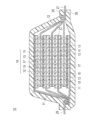
- FIG. 1 is a schematic cross-sectional view showing a basic configuration of a non-aqueous electrolyte lithium ion secondary battery that is not a flat (stacked) bipolar type, which is an embodiment of a non-aqueous electrolyte secondary battery.
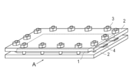
- FIG. 2A is a schematic view of a non-aqueous electrolyte secondary battery which is a preferred embodiment of the present invention.
- FIG. 2B is an arrow view from the direction A in FIG. 2A.
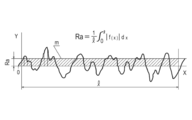
- FIG. 2 is a diagram illustrating Formula 1 defined in JIS B B0601-1994 and the surface roughness Ra obtained by the formula 1.
- FIG. 1 is a schematic cross-sectional view showing a basic configuration of a non-aqueous electrolyte lithium ion secondary battery that is not a flat (stacked) bipolar type, which is an embodiment of a non-aqueous electrolyte secondary battery.
- FIG. 2A is a schematic view of a non-aqueous electrolyte secondary battery which is
- the present invention provides a power generation element including a positive electrode in which a positive electrode active material layer is formed on the surface of a positive electrode current collector, a negative electrode in which a negative electrode active material layer is formed on the surface of a negative electrode current collector, and a separator.
- a non-aqueous electrolyte secondary battery having a negative electrode active material layer having a density of 1.3 to 1.6 g / cm 3 , the negative electrode active material layer containing an aqueous binder, and a surface on the separator side of the negative electrode active material layer
- This is a nonaqueous electrolyte secondary battery having a surface centerline average roughness (Ra) of 0.5 to 1.0 ⁇ m.
- the water-based binder can use water as a solvent in producing the active material layer, there are various advantages and the binding force for binding the active material is high.
- the present inventors have found that when a water-based binder is used for the negative electrode active material layer, there is a problem that a large amount of gas is generated at the first charge / discharge compared to a negative electrode using an organic solvent-based binder. . This is because the water of the solvent used for dissolving (dispersing) the aqueous binder remains in the electrode, and this water decomposes into a gas, so that more gas is generated than the organic solvent binder. It is done.
- the size of the electrode is increased to improve the energy density. Heterogeneous reactions are also likely to occur.
- the configuration of the present invention has been completed based on the idea that it can be discharged out of the system.
- the density of the negative electrode active material layer and the negative electrode surface roughness are within a specific range.
- the density of the negative electrode active material layer it becomes possible to pass the generated gas.
- the surface roughness of the negative electrode active material layer the gas passes through the gas generation element. It is thought that gas is discharged out of the system from the negative electrode surface. That is, the configuration of the present invention improves the battery performance by properly discharging the gas vertical passage and the electrode surface passage to smoothly discharge the generated gas out of the system. is there.
- the present invention even when an aqueous binder is used as the binder of the negative electrode active material layer, the generated gas is easily released to the outside of the electrode. Fewer non-aqueous electrolyte secondary batteries are possible.
- non-aqueous electrolyte lithium ion secondary battery will be described as a preferred embodiment of the non-aqueous electrolyte secondary battery, but is not limited to the following embodiment.
- the same elements are denoted by the same reference numerals, and redundant description is omitted.
- the dimensional ratios in the drawings are exaggerated for convenience of explanation, and may be different from the actual ratios.
- FIG. 1 is a schematic cross-sectional view schematically showing a basic configuration of a non-aqueous electrolyte lithium ion secondary battery (hereinafter also simply referred to as “stacked battery”) that is not a flat (stacked) bipolar type.
- the stacked battery 10 of the present embodiment has a structure in which a substantially rectangular power generation element 21 in which a charge / discharge reaction actually proceeds is sealed inside a battery exterior material 29 that is an exterior body.
- the power generation element 21 has a configuration in which a positive electrode, a separator 17, and a negative electrode are stacked.
- the separator 17 contains a nonaqueous electrolyte (for example, a liquid electrolyte).
- the positive electrode has a structure in which the positive electrode active material layer 13 is disposed on both surfaces of the positive electrode current collector 11.
- the negative electrode has a structure in which the negative electrode active material layers 15 are disposed on both surfaces of the negative electrode current collector 12.
- the negative electrode, the electrolyte layer, and the positive electrode are laminated in this order so that one positive electrode active material layer 13 and the negative electrode active material layer 15 adjacent thereto are opposed to each other with a separator 17 therebetween.
- the adjacent positive electrode, electrolyte layer, and negative electrode constitute one unit cell layer 19. Therefore, it can be said that the stacked battery 10 shown in FIG. 1 has a configuration in which a plurality of single battery layers 19 are stacked and electrically connected in parallel.
- the positive electrode active material layer 13 is disposed on only one side of the outermost positive electrode current collector located on both outermost layers of the power generation element 21, but active material layers may be provided on both sides. That is, instead of using a current collector dedicated to the outermost layer provided with an active material layer only on one side, a current collector having an active material layer on both sides may be used as it is as an outermost current collector.
- the arrangement of the positive electrode and the negative electrode is reversed from that in FIG. 1, so that the outermost layer negative electrode current collector is positioned on both outermost layers of the power generation element 21, and the outermost layer negative electrode current collector is disposed on one or both surfaces.
- a negative electrode active material layer may be disposed.
- the positive electrode current collector 11 and the negative electrode current collector 12 are each provided with a positive electrode current collector plate (tab) 25 and a negative electrode current collector plate (tab) 27 that are electrically connected to the respective electrodes (positive electrode and negative electrode). It has the structure led out of the battery exterior material 29 so that it may be pinched
- the positive electrode current collector plate 25 and the negative electrode current collector plate 27 are ultrasonically welded to the positive electrode current collector 11 and the negative electrode current collector 12 of each electrode, respectively, via a positive electrode lead and a negative electrode lead (not shown) as necessary. Or resistance welding or the like.
- FIG. 1 shows a flat battery (stacked battery) that is not a bipolar battery, but a positive electrode active material layer that is electrically coupled to one surface of the current collector and the opposite side of the current collector.
- a bipolar battery including a bipolar electrode having a negative electrode active material layer electrically coupled to the surface.
- one current collector also serves as a positive electrode current collector and a negative electrode current collector.
- the density of the negative electrode active material layer is 1.3 to 1.6 g / cm 3 .
- the density of the negative electrode active material layer exceeds 1.6 g / cm 3 , since the density of the active material layer is high, the generated gas does not escape from the electrode, and the long-term cycle characteristics deteriorate.
- the density of the negative electrode active material layer is less than 1.3 g / cm 3 , the connectivity of the active material is lowered and the electron conductivity is lowered, so that the battery performance is lowered.
- the density of the negative electrode active material layer is preferably 1.3 to 1.55 g / cm 3 because the effects of the present invention are more exhibited.
- the density of the negative electrode active material layer In order to control the density of the negative electrode active material layer within the above range, the density can be controlled by appropriately adjusting the pressing pressure at the time of producing the electrode.
- the density of the negative electrode active material layer represents the mass of the active material layer per unit volume. Specifically, after removing the negative electrode active material layer from the battery, removing the solvent and the like present in the electrolyte solution, the electrode volume is obtained from the long side, the short side, and the height, and after measuring the weight of the active material layer, It can be determined by dividing weight by volume.
- the surface centerline average roughness (Ra) of the surface on the separator side of the negative electrode active material layer is 0.5 to 1.0 ⁇ m.
- the center line average roughness (Ra) of the negative electrode active material layer is less than 0.5 ⁇ m, long-term cycle characteristics deteriorate. This is presumably because the gas generated in the power generation element is difficult to be discharged out of the system because the surface roughness is small.
- the center line average roughness (Ra) of the negative electrode active material layer exceeds 1.0 ⁇ m, the electron conductivity in the battery element is lowered, so that the battery characteristics are lowered.
- the centerline average roughness Ra means that only the reference length is extracted from the roughness curve in the direction of the average line, the x axis is in the direction of the average line of the extracted portion, and the y axis is in the direction of the vertical magnification.
- the value obtained by the following formula 1 is expressed in micrometers ( ⁇ m) (JIS-B0601-1994) (see FIG. 3). thing).
- the value of Ra is measured by using a stylus type or non-contact type surface roughness meter that is generally widely used, for example, by a method defined in JIS-B0601-1994. There are no restrictions on the manufacturer or model of the device.
- Olympus's model number: EXT-OLS3000 was used, and Ra was obtained by a roughness analyzer (analysis software attached to the device) according to the method defined in JIS-B0601.
- Either the contact method (stylus type using a diamond needle or the like) or the non-contact method (non-contact detection using a laser beam or the like) can be used, but in the study in the present invention, the measurement was performed by the contact method.
- the surface roughness Ra defined in the present invention can be measured relatively easily as in the method described in the examples, the surface roughness Ra defined in the present invention is a stage in which the active material layer is formed on the current collector in the manufacturing process. Measure with However, the measurement can be performed even after the battery is completed, and the results are almost the same as those in the manufacturing stage. Therefore, the surface roughness after the battery is completed may satisfy the above Ra range.
- the surface roughness of the negative electrode active material layer is that on the separator side of the negative electrode active material layer.
- the surface roughness of the negative electrode takes into account the active material shape, particle diameter, active material blending amount, etc. contained in the negative electrode active material layer, for example, by adjusting the press pressure during active material layer formation, etc. It can adjust so that it may become the said range.
- the shape of the active material varies depending on the type and manufacturing method, and the shape can be controlled by pulverization, for example, spherical (powder), plate, needle, column, square Etc. Therefore, in order to adjust the surface roughness in consideration of the shape used for the active material layer, active materials having various shapes may be combined.
- the negative electrode active material layer includes a negative electrode active material.
- the negative electrode active material include carbon materials such as graphite (graphite), soft carbon, and hard carbon, lithium-transition metal composite oxides (for example, Li 4 Ti 5 O 12 ), metal materials, lithium alloy negative electrode materials, and the like. Is mentioned. In some cases, two or more negative electrode active materials may be used in combination. Preferably, from the viewpoint of capacity and output characteristics, a carbon material or a lithium-transition metal composite oxide is used as the negative electrode active material. Of course, negative electrode active materials other than those described above may be used.
- the average particle diameter of each active material contained in the negative electrode active material layer is not particularly limited, but is preferably 1 to 100 ⁇ m, more preferably 1 to 30 ⁇ m from the viewpoint of high output.
- the negative electrode active material layer contains at least an aqueous binder.
- water-based binders can be greatly reduced in capital investment on the production line and reduced environmental load because it is water vapor that occurs during drying. There is an advantage.
- the water-based binder refers to a binder using water as a solvent or a dispersion medium, and specifically includes a thermoplastic resin, a polymer having rubber elasticity, a water-soluble polymer, or a mixture thereof.
- the binder using water as a dispersion medium refers to a polymer that includes all expressed as latex or emulsion and is emulsified or suspended in water.
- kind a polymer latex that is emulsion-polymerized in a system that self-emulsifies.
- water-based binders include styrene polymers (styrene-butadiene rubber, styrene-vinyl acetate copolymer, styrene-acrylic copolymer, etc.), acrylonitrile-butadiene rubber, methyl methacrylate-butadiene rubber, ) Acrylic polymers (polyethyl acrylate, polyethyl methacrylate, polypropyl acrylate, polymethyl methacrylate (methyl methacrylate rubber), polypropyl methacrylate, polyisopropyl acrylate, polyisopropyl methacrylate, polybutyl acrylate, polybutyl methacrylate, polyhexyl acrylate , Polyhexyl methacrylate, polyethylhexyl acrylate, polyethylhexyl methacrylate, polylauryl acrylate, polylauryl meta Acrylate, etc.), polytyren
- the aqueous binder may contain at least one rubber binder selected from the group consisting of styrene-butadiene rubber, acrylonitrile-butadiene rubber, methyl methacrylate-butadiene rubber, and methyl methacrylate rubber from the viewpoint of binding properties. preferable. Furthermore, it is preferable that the water-based binder contains styrene-butadiene rubber because of good binding properties.
- Water-soluble polymers suitable for use in combination with styrene-butadiene rubber include polyvinyl alcohol and modified products thereof, starch and modified products thereof, cellulose derivatives (such as carboxymethyl cellulose, methyl cellulose, hydroxyethyl cellulose, and salts thereof), polyvinyl Examples include pyrrolidone, polyacrylic acid (salt), or polyethylene glycol. Among them, it is preferable to combine styrene-butadiene rubber and carboxymethyl cellulose as a binder.
- the content of the aqueous binder is preferably 80 to 100% by mass, preferably 90 to 100% by mass, and preferably 100% by mass.
- the binder other than the water-based binder include binders used in the following positive electrode active material layer.
- the amount of the binder contained in the negative electrode active material layer is not particularly limited as long as it can bind the active material, but preferably 0.5 to 15% by mass with respect to the active material layer. More preferably, it is 1 to 10% by mass, and further preferably 2 to 4% by mass. Since the water-based binder has high binding power, the active material layer can be formed with a small amount of addition as compared with the organic solvent-based binder. Accordingly, the content of the aqueous binder in the active material layer is preferably 0.5 to 15% by mass, more preferably 1 to 10% by mass, and still more preferably 2% with respect to the active material layer. Is 4% by mass.
- the negative electrode active material layer further includes other additives such as a conductive additive, an electrolyte (polymer matrix, ion conductive polymer, electrolytic solution, etc.), and a lithium salt for improving ion conductivity, as necessary.
- the conductive assistant means an additive blended to improve the conductivity of the positive electrode active material layer or the negative electrode active material layer.
- the conductive auxiliary agent include carbon materials such as carbon black such as acetylene black, graphite, and carbon fiber.
- electrolyte salt examples include Li (C 2 F 5 SO 2 ) 2 N, LiPF 6 , LiBF 4 , LiClO 4 , LiAsF 6 , LiCF 3 SO 3 and the like.
- Examples of the ion conductive polymer include polyethylene oxide (PEO) and polypropylene oxide (PPO) polymers.
- the compounding ratio of the components contained in the negative electrode active material layer and the positive electrode active material layer described later is not particularly limited.
- the blending ratio can be adjusted by appropriately referring to known knowledge about lithium ion secondary batteries.
- the thickness of each active material layer is not particularly limited, and conventionally known knowledge about the battery can be appropriately referred to. As an example, the thickness of each active material layer is about 2 to 100 ⁇ m.
- the positive electrode active material layer contains an active material and, if necessary, other additives such as a conductive additive, a binder, an electrolyte (polymer matrix, ion conductive polymer, electrolyte, etc.), and a lithium salt for increasing ionic conductivity.
- a conductive additive such as aluminum silicate, aluminum silicate, magnesium silicate, magnesium silicate, magnesium silicate, magnesium silicate, magnesium silicate, magnesium silicate, etc.
- an electrolyte polymer matrix, ion conductive polymer, electrolyte, etc.
- a lithium salt for increasing ionic conductivity.
- the positive electrode active material layer includes a positive electrode active material.
- the positive electrode active material include LiMn 2 O 4 , LiCoO 2 , LiNiO 2 , Li (Ni—Mn—Co) O 2, and lithium-- such as those in which some of these transition metals are substituted with other elements.
- Examples include transition metal composite oxides, lithium-transition metal phosphate compounds, and lithium-transition metal sulfate compounds.
- two or more positive electrode active materials may be used in combination.
- a lithium-transition metal composite oxide is used as the positive electrode active material.
- NMC composite oxide Li (Ni—Mn—Co) O 2 and those in which some of these transition metals are substituted with other elements (hereinafter also simply referred to as “NMC composite oxide”) are used.
- the NMC composite oxide has a layered crystal structure in which a lithium atomic layer and a transition metal (Mn, Ni, and Co are arranged in order) are stacked alternately via an oxygen atomic layer.
- One Li atom is contained, and the amount of Li that can be taken out is twice that of the spinel lithium manganese oxide, that is, the supply capacity is doubled, so that a high capacity can be obtained.
- the NMC composite oxide includes a composite oxide in which a part of the transition metal element is substituted with another metal element.
- Other elements in that case include Ti, Zr, Nb, W, P, Al, Mg, V, Ca, Sr, Cr, Fe, B, Ga, In, Si, Mo, Y, Sn, V, Cu , Ag, Zn, etc., preferably Ti, Zr, Nb, W, P, Al, Mg, V, Ca, Sr, Cr, more preferably Ti, Zr, P, Al, Mg, From the viewpoint of improving cycle characteristics, Ti, Zr, Al, Mg, and Cr are more preferable.
- a represents the atomic ratio of Li
- b represents the atomic ratio of Ni
- c represents the atomic ratio of Mn
- d represents the atomic ratio of Co
- x represents the atomic ratio of M. Represents. From the viewpoint of cycle characteristics, it is preferable that 0.4 ⁇ b ⁇ 0.6 in the general formula (1).
- the composition of each element can be measured by, for example, inductively coupled plasma (ICP) emission spectrometry.
- ICP inductively coupled plasma
- Ni nickel
- Co cobalt
- Mn manganese
- Ti or the like partially replaces the transition metal in the crystal lattice. From the viewpoint of cycle characteristics, it is preferable that a part of the transition element is substituted with another metal element, and it is particularly preferable that 0 ⁇ x ⁇ 0.3 in the general formula (1). Since at least one selected from the group consisting of Ti, Zr, Nb, W, P, Al, Mg, V, Ca, Sr, and Cr is dissolved, the crystal structure is stabilized. It is considered that the battery capacity can be prevented from decreasing even if the above is repeated, and that excellent cycle characteristics can be realized.
- b, c and d are 0.44 ⁇ b ⁇ 0.51, 0.27 ⁇ c ⁇ 0.31, 0.19 ⁇ d ⁇ 0.26. It is preferable from the viewpoint of improving the balance between capacity and life characteristics.
- positive electrode active materials other than those described above may be used.
- the average particle diameter of each active material contained in the positive electrode active material layer is not particularly limited, but is preferably 1 to 100 ⁇ m, more preferably 1 to 20 ⁇ m from the viewpoint of increasing the output.
- a binder used for a positive electrode active material layer For example, the following materials are mentioned. Polyethylene, polypropylene, polyethylene terephthalate (PET), polyether nitrile, polyacrylonitrile, polyimide, polyamide, cellulose, carboxymethyl cellulose (CMC) and its salts, ethylene-vinyl acetate copolymer, polyvinyl chloride, styrene-butadiene rubber (SBR) ), Isoprene rubber, butadiene rubber, ethylene / propylene rubber, ethylene / propylene / diene copolymer, styrene / butadiene / styrene block copolymer and hydrogenated product thereof, styrene / isoprene / styrene block copolymer and hydrogenated product thereof.
- Thermoplastic polymers such as products, polyvinylidene fluoride (PVdF), polyt
- the amount of the binder contained in the positive electrode active material layer is not particularly limited as long as it is an amount capable of binding the active material, but preferably 0.5 to 15% by mass with respect to the active material layer. More preferably, it is 1 to 10% by mass.
- additives other than the binder the same additives as those in the negative electrode active material layer column can be used.
- the separator has a function of holding an electrolyte and ensuring lithium ion conductivity between the positive electrode and the negative electrode, and a function as a partition wall between the positive electrode and the negative electrode.
- the escape of gas generated by controlling the density of the negative electrode active material layer and the surface roughness of the surface of the negative electrode active material layer is improved, but in order to further improve the gas discharge, the negative electrode active material layer is improved. It is also necessary to consider the discharge of gas that has passed through the material layer and reached the separator. From such a viewpoint, it is more preferable that the air permeability and the porosity of the separator are within an appropriate range.
- the air permeability (Gurley value) of the separator is preferably 200 (units / 100 cc) or less.
- the air permeability of the separator is 200 (units / 100 cc) or less, the escape of gas generated at the time of initial charge is improved, the battery has a good capacity retention rate after cycling, and also functions as a separator. Short circuit prevention and mechanical properties are sufficient.
- the lower limit of the air permeability is not particularly limited, but is usually 100 (units / 100 cc) or more.
- the air permeability of the separator is a value according to the measurement method of JIS P8117 (2009).
- the porosity of the separator is preferably 40 to 65%.
- the porosity of the separator is 40 to 65%, the escape of gas generated at the time of initial charge is improved, the battery has a good capacity maintenance rate after the cycle, and the function as a separator is prevented from being short-circuited. Mechanical properties are also sufficient.
- the porosity a value obtained as a volume ratio from the density of the resin as the raw material of the separator and the density of the separator of the final product is adopted. For example, when the density of the raw material resin is ⁇ and the bulk density of the separator is ⁇ ′, the porosity is expressed by 100 ⁇ (1 ⁇ ′ / ⁇ ).
- separator examples include a separator made of a porous sheet made of a polymer or fiber that absorbs and holds the electrolyte and a nonwoven fabric separator.
- a microporous (microporous film) can be used as the separator of the porous sheet made of polymer or fiber.
- the porous sheet made of the polymer or fiber include polyolefins such as polyethylene (PE) and polypropylene (PP); a laminate in which a plurality of these are laminated (for example, three layers of PP / PE / PP) And a microporous (microporous membrane) separator made of a hydrocarbon resin such as polyimide, aramid, polyvinylidene fluoride-hexafluoropropylene (PVdF-HFP), glass fiber, and the like.
- PE polyethylene
- PP polypropylene
- a microporous (microporous membrane) separator made of a hydrocarbon resin such as polyimide, aramid, polyvinylidene fluoride-hexafluoropropylene (PVdF-HFP), glass fiber, and the like.
- the thickness of the microporous (microporous membrane) separator cannot be uniquely defined because it varies depending on the intended use. For example, in applications such as secondary batteries for driving motors such as electric vehicles (EV), hybrid electric vehicles (HEV), and fuel cell vehicles (FCV), it is 4 to 60 ⁇ m in a single layer or multiple layers. Is desirable.
- the fine pore diameter of the microporous (microporous membrane) separator is desirably 1 ⁇ m or less (usually a pore diameter of about several tens of nm).
- nonwoven fabric separator cotton, rayon, acetate, nylon, polyester; polyolefins such as PP and PE; conventionally known ones such as polyimide and aramid are used alone or in combination.
- the bulk density of the nonwoven fabric is not particularly limited as long as sufficient battery characteristics can be obtained by the impregnated polymer gel electrolyte.
- the thickness of the nonwoven fabric separator may be the same as that of the electrolyte layer, and is preferably 5 to 200 ⁇ m, particularly preferably 10 to 100 ⁇ m.
- the separator may be a separator in which a heat-resistant insulating layer is laminated on a porous substrate.
- the heat-resistant insulating layer is a ceramic layer containing inorganic particles and a binder.
- the separator includes an electrolyte.
- the electrolyte is not particularly limited as long as it can exhibit such a function, but a liquid electrolyte or a gel polymer electrolyte is used.
- the liquid electrolyte functions as a lithium ion carrier.
- the liquid electrolyte has a form in which a lithium salt as a supporting salt is dissolved in an organic solvent as a plasticizer.
- organic solvent include carbonates such as ethylene carbonate (EC), propylene carbonate (PC), dimethyl carbonate (DMC), diethyl carbonate (DEC), and ethyl methyl carbonate.
- EC ethylene carbonate
- PC propylene carbonate
- DMC dimethyl carbonate
- DEC diethyl carbonate
- ethyl methyl carbonate Li (CF 3 SO 2) 2 N, Li (C 2 F 5 SO 2) 2 N, LiPF 6, LiBF 4, LiClO 4, LiAsF 6, LiTaF such 6, LiCF 3 SO 3
- a compound that can be added to the active material layer of the electrode can be similarly employed.
- the liquid electrolyte may further contain additives other than the components described above.
- additives include, for example, vinylene carbonate, methyl vinylene carbonate, dimethyl vinylene carbonate, phenyl vinylene carbonate, diphenyl vinylene carbonate, ethyl vinylene carbonate, diethyl vinylene carbonate, vinyl ethylene carbonate, 1,2-divinyl ethylene carbonate.
- vinylene carbonate, methyl vinylene carbonate, and vinyl ethylene carbonate are preferable, and vinylene carbonate and vinyl ethylene carbonate are more preferable.
- These cyclic carbonates may be used alone or in combination of two or more.
- the gel polymer electrolyte has a configuration in which the above liquid electrolyte is injected into a matrix polymer (host polymer) made of an ion conductive polymer.
- a gel polymer electrolyte as the electrolyte is superior in that the fluidity of the electrolyte is lost and the ion conductivity between the layers is easily cut off.
- the ion conductive polymer used as the matrix polymer (host polymer) include polyethylene oxide (PEO), polypropylene oxide (PPO), and copolymers thereof. In such polyalkylene oxide polymers, electrolyte salts such as lithium salts can be well dissolved.
- the matrix polymer of the gel electrolyte or the intrinsic polymer electrolyte can express excellent mechanical strength by forming a crosslinked structure.
- thermal polymerization, ultraviolet polymerization, radiation polymerization, electron beam polymerization, etc. are performed on a polymerizable polymer (for example, PEO or PPO) for forming a polymer electrolyte using an appropriate polymerization initiator.
- a polymerization treatment may be performed.
- examples of the metal include aluminum, nickel, iron, stainless steel, titanium, copper, and other alloys.
- a clad material of nickel and aluminum, a clad material of copper and aluminum, or a plating material of a combination of these metals can be preferably used.
- covered on the metal surface may be sufficient.
- aluminum, stainless steel, and copper are preferable from the viewpoints of electronic conductivity and battery operating potential.
- the size of the current collector is determined according to the intended use of the battery. For example, if it is used for a large battery that requires a high energy density, a current collector having a large area is used. There is no particular limitation on the thickness of the current collector.
- the thickness of the current collector is usually about 1 to 100 ⁇ m.
- the material which comprises a current collector plate (25, 27) is not restrict
- a constituent material of the current collector plate for example, metal materials such as aluminum, copper, titanium, nickel, stainless steel (SUS), and alloys thereof are preferable. From the viewpoint of light weight, corrosion resistance, and high conductivity, aluminum and copper are more preferable, and aluminum is particularly preferable.
- the positive electrode current collector plate 25 and the negative electrode current collector plate 27 may be made of the same material or different materials.
- the battery outer case 29 a known metal can case can be used, and a bag-like case using a laminate film containing aluminum that can cover the power generation element can be used.
- a laminate film having a three-layer structure in which PP, aluminum, and nylon are laminated in this order can be used as the laminate film, but the laminate film is not limited thereto.
- a laminate film is desirable from the viewpoint that it is excellent in high output and cooling performance, and can be suitably used for a battery for large equipment for EV and HEV.
- the exterior body is more preferably a laminate film containing aluminum.
- the inner volume of the exterior body is preferably larger than the volume of the power generation element.
- the internal volume of the exterior body refers to the volume in the exterior body before evacuation after sealing with the exterior body.
- the volume of the power generation element is the volume of the space occupied by the power generation element, and includes a hole in the power generation element. Since the inner volume of the exterior body is larger than the volume of the power generation element, there is a volume capable of storing gas when gas is generated. Therefore, the gas is smoothly discharged out of the system, and the generated gas hardly affects the battery behavior, and the battery characteristics are improved. In addition, when gas is generated, there is a surplus part that can store the gas in the exterior body, so that the volume of the power generation element can be kept constant. Can be sustained.
- the internal volume of the exterior body is preferably large to some extent so that gas can be stored. Specifically, the volume of the volume excluding the pores of the power generation element is 0.03 to 0.12, and the content of the exterior body The product is preferably larger than the volume of the power generating element.
- the negative electrode active material layer is preferably rectangular, and the length of the rectangular short side is preferably 100 mm or more. Such a large battery can be used for vehicle applications.
- the upper limit of the length of the rectangular short side is not particularly limited, but is usually 250 mm or less.
- the value of the ratio of the battery area to the rated capacity (the maximum value of the projected area of the battery including the battery outer casing) is 5 cm 2 / Ah or more, and the rated capacity is A battery having a capacity of 3 Ah or more has a large amount of gas generation because the battery area per unit capacity is large.
- the nonaqueous electrolyte secondary battery according to the present embodiment is a battery having a large size as described above, because the merit due to the expression of the effects of the present invention is greater.
- the aspect ratio of the rectangular electrode is preferably 1 to 3, and more preferably 1 to 2. The electrode aspect ratio is defined as the aspect ratio of the rectangular positive electrode active material layer.
- the group pressure applied to the power generation element is preferably 0.07 to 0.7 kgf / cm 2 (6.86 to 68.6 kPa).
- the group pressure applied to the power generation element is 0.1 to 0.7 kgf / cm 2 (9.80 to 68.6 kPa).
- the group pressure refers to an external force applied to the power generation element
- the group pressure applied to the power generation element sandwiches a pressure sensitive paper in a portion where pressure is to be measured, and after adding pressure, removes the pressure once, It can be measured by reading the pressure applied to the pressure sensitive paper.
- the control of the group pressure is not particularly limited, but can be controlled by applying an external force physically or directly to the power generation element and controlling the external force.
- a pressure member that applies pressure to the exterior body it is preferable to use. That is, a preferred embodiment of the present invention further includes a pressure member that applies pressure to the outer package so that the group pressure applied to the power generation element is 0.07 to 0.7 kgf / cm 2. It is a secondary battery.
- FIG. 2A is a schematic view of a non-aqueous electrolyte secondary battery which is another preferred embodiment of the present invention
- FIG. 2B is a view as viewed from the direction A in FIG. 2A.
- the exterior body 1 enclosing the power generation element has a rectangular flat shape, and an electrode tab 4 for taking out electric power is drawn out from the side portion.
- the power generation element is wrapped by a battery outer package, and the periphery thereof is heat-sealed.
- the power generation element is sealed with the electrode tab 4 pulled out.
- the power generation element corresponds to the power generation element 21 of the lithium ion secondary battery 10 shown in FIG. 1 described above.
- FIG. 1 the power generation element 21 of the lithium ion secondary battery 10 shown in FIG. 1 described above.
- the pressurizing member is disposed for the purpose of controlling the group pressure applied to the power generation element to be 0.07 to 0.7 kgf / cm 2 .
- the pressure member include a rubber material such as a urethane rubber sheet, and a metal plate such as aluminum and SUS.
- the pressure member can continuously apply a constant pressure to the power generation element, it is preferable to further include a fixing member for fixing the pressure member. Further, the group pressure applied to the power generation element can be easily controlled by adjusting the fixing of the fixing jig to the pressing member.
- the tab removal shown in FIG. 2 is not particularly limited.
- the positive electrode tab and the negative electrode tab may be pulled out from both sides, or the positive electrode tab and the negative electrode tab may be divided into a plurality of parts and taken out from each side. It is not a thing.
- the assembled battery is configured by connecting a plurality of batteries. Specifically, at least two or more are used, and are configured by serialization, parallelization, or both. Capacitance and voltage can be freely adjusted by paralleling in series.
- a small assembled battery that can be attached and detached by connecting a plurality of batteries in series or in parallel. Then, a plurality of small assembled batteries that can be attached and detached are connected in series or in parallel to provide a large capacity and large capacity suitable for vehicle drive power supplies and auxiliary power supplies that require high volume energy density and high volume output density.
- An assembled battery having an output can also be formed. How many batteries are connected to make an assembled battery, and how many small assembled batteries are stacked to make a large-capacity assembled battery depends on the battery capacity of the mounted vehicle (electric vehicle) It may be determined according to the output.
- the non-aqueous electrolyte secondary battery has excellent output characteristics, maintains a discharge capacity even after long-term use, and has good cycle characteristics. Vehicle applications such as electric vehicles, hybrid electric vehicles, fuel cell vehicles, and hybrid fuel cell vehicles require higher capacity, larger size, and longer life than electric and portable electronic devices. . Therefore, the nonaqueous electrolyte secondary battery can be suitably used as a vehicle power source, for example, a vehicle driving power source or an auxiliary power source.
- a battery or an assembled battery formed by combining a plurality of these batteries can be mounted on the vehicle.
- a plug-in hybrid electric vehicle having a long EV mileage or an electric vehicle having a long charge mileage can be formed by mounting such a battery.
- a car a hybrid car, a fuel cell car, an electric car (four-wheeled vehicles (passenger cars, trucks, buses, commercial vehicles, light cars, etc.) This is because it can be used for motorcycles (including motorcycles) and tricycles) to provide a long-life and highly reliable automobile.
- the application is not limited to automobiles.
- it can be applied to various power sources for moving vehicles such as other vehicles, for example, trains, and power sources for mounting such as uninterruptible power supplies. It is also possible to use as.
- Example 1 Preparation of Electrolyte Solution A mixed solvent (30:30:40 (volume ratio)) of ethylene carbonate (EC), ethyl methyl carbonate (EMC), and diethyl carbonate (DEC) was used as a solvent. Further, 1.0M LiPF 6 was used as a lithium salt. Further, 2% by mass of vinylene carbonate was added to the total of 100% by mass of the solvent and the lithium salt to prepare an electrolytic solution. Note that “1.0 M LiPF 6 ” means that the lithium salt (LiPF 6 ) concentration in the mixture of the mixed solvent and the lithium salt is 1.0 M.
- a solid content comprising 85% by mass of LiMn 2 O 4 (average particle size: 15 ⁇ m) as a positive electrode active material, 5% by mass of acetylene black as a conductive additive, and 10% by mass of PVdF as a binder was prepared.
- NMP N-methyl-2-pyrrolidone
- the positive electrode slurry was applied to both surfaces of an aluminum foil (20 ⁇ m) as a current collector, dried and pressed to produce a positive electrode having a single-side coating amount of 18 mg / cm 2 and a double-sided thickness of 157 ⁇ m (including foil).
- the negative electrode slurry was applied to both sides of a copper foil (15 ⁇ m) as a current collector, dried and pressed to produce a negative electrode having a single-side coating amount of 5.1 mg / cm 2 and a thickness of 82 ⁇ m (including foil). .
- the surface center line average roughness (Ra) of the prepared negative electrode active material layer was measured using a contact type surface roughness meter (manufactured by Olympus, model number: LEXT-OLS3000).
- Step of completing cell The positive electrode produced above was cut into a 210 ⁇ 184 mm rectangular shape (rectangular shape), and the negative electrode was cut into a 215 ⁇ 188 mm rectangular shape (rectangular shape) (15 positive electrodes and 16 negative electrodes).
- the positive electrode and the negative electrode were alternately laminated through a separator (polyolefin microporous film, thickness 25 ⁇ m) of 219 ⁇ 191 mm to produce a power generation element.
- a tab is welded to each of the positive electrode and the negative electrode, and the battery is completed by sealing with an electrolytic solution in an exterior made of an aluminum laminate film, a urethane rubber sheet (thickness 3 mm) larger than the electrode area, and an Al plate (thickness 5 mm). ) To sandwich the battery and pressurize it to the group pressure shown in Table 1 to complete the unit cell.
- the rated capacity of the battery thus fabricated was 14.6 Ah, and the ratio of the battery area to the rated capacity was 34.8 cm 2 / Ah.
- the rated capacity of the battery (single cell) was determined as follows.
- the rated capacity is about 10 hours after injecting the electrolyte for the test battery, and the initial charge is performed. Thereafter, the temperature is measured by the following procedures 1 to 5 at a temperature of 25 ° C. and a voltage range of 3.0 V to 4.15 V.
- Procedure 1 After reaching 4.15V by constant current charging at 0.2C, pause for 5 minutes.
- Procedure 2 After Procedure 1, charge for 1.5 hours with constant voltage charging and rest for 5 minutes.
- Procedure 3 After reaching 3.0 V by constant current discharge of 0.2 C, discharge at constant voltage discharge for 2 hours, and then rest for 10 seconds.
- Procedure 4 After reaching 4.1 V by constant current charging at 0.2 C, charge for 2.5 hours by constant voltage charging, and then rest for 10 seconds.
- Procedure 5 After reaching 3.0V by constant current discharge of 0.2 C, discharge at constant voltage discharge for 2 hours, and then stop for 10 seconds.
- the discharge capacity (CCCV discharge capacity) in the discharge from the constant current discharge to the constant voltage discharge in the procedure 5 is defined as the rated capacity.
- Example 2 to 10 and Comparative Examples 1 to 3 In Comparative Example 1, natural graphite (manufactured by Hitachi Chemical Co., Ltd., shape: scaly graphite, average particle size: 20 ⁇ m) is used as the negative electrode active material, and in Comparative Example 3, natural graphite (manufactured by Hitachi Chemical Co., Ltd., shape) is used as the negative electrode active material.
- natural graphite manufactured by Hitachi Chemical Co., Ltd., shape: scaly graphite, average particle size: 20 ⁇ m
- Comparative Example 3 natural graphite (manufactured by Hitachi Chemical Co., Ltd., shape) is used as the negative electrode active material.
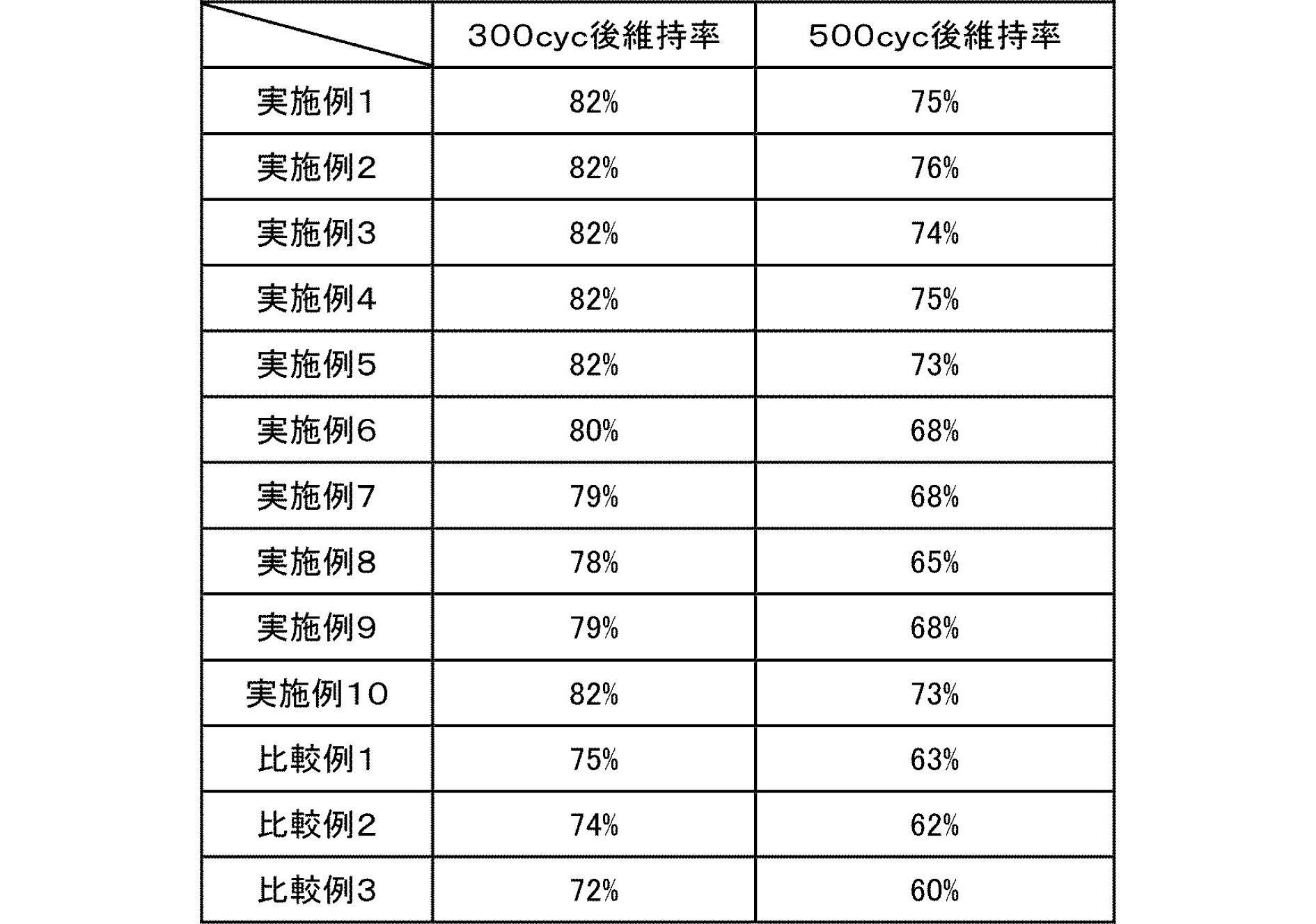
- the nonaqueous electrolyte secondary battery (unit cell) produced as described above was evaluated by a charge / discharge performance test. This charge / discharge performance test was performed in a thermostatic chamber maintained at 45 ° C. after the battery temperature was set to 45 ° C. Charging was performed by constant current charging (CC) to 4.2 V at a current rate of 1 C, and then charging at a constant voltage (CV) for 2.5 hours. Thereafter, after a 10-minute rest period, discharging was performed at a current rate of 1 C up to 2.5 V, followed by a 10-minute rest period. These were made into 1 cycle, and the charging / discharging test was implemented. The ratio of discharge after 300 cycles and 500 cycles with respect to the initial discharge capacity was defined as the capacity maintenance rate. The results are shown in Table 2.
Landscapes
- Chemical & Material Sciences (AREA)
- General Chemical & Material Sciences (AREA)
- Chemical Kinetics & Catalysis (AREA)
- Electrochemistry (AREA)
- Engineering & Computer Science (AREA)
- Manufacturing & Machinery (AREA)
- Inorganic Chemistry (AREA)
- Materials Engineering (AREA)
- Physics & Mathematics (AREA)
- Condensed Matter Physics & Semiconductors (AREA)
- General Physics & Mathematics (AREA)
- Battery Electrode And Active Subsutance (AREA)
- Secondary Cells (AREA)
- Sealing Battery Cases Or Jackets (AREA)
- Cell Separators (AREA)
Abstract
Description
本発明において、負極活物質層の密度は、1.3~1.6g/cm3である。負極活物質層の密度が1.6g/cm3を超えると、活物質層の密度が高いために、発生したガスが電極内から抜けず、長期サイクル特性が低下する。また、負極活物質層の密度が1.3g/cm3未満であると、活物質の連通性が低下し、電子伝導性が低下するため、電池性能が低下する。負極活物質層の密度は、本発明の効果がより発揮されることから、1.3~1.55g/cm3であることが好ましい。負極活物質層の密度を上記範囲内に制御するためには、電極を製造する際のプレス圧を適宜調整することによって、制御できる。なお、負極活物質層の密度は、単位体積あたりの活物質層質量を表す。具体的には、電池から負極活物質層を取り出し、電解液中などに存在する溶媒等を除去後、電極体積を長辺、短辺、高さから求め、活物質層の重量を測定後、重量を体積で除することによって求めることができる。

正極活物質層は活物質を含み、必要に応じて、導電助剤、バインダー、電解質(ポリマーマトリックス、イオン伝導性ポリマー、電解液など)、イオン伝導性を高めるためのリチウム塩などのその他の添加剤をさらに含む。
セパレータは、電解質を保持して正極と負極との間のリチウムイオン伝導性を確保する機能、および正極と負極との間の隔壁としての機能を有する。
集電体を構成する材料に特に制限はないが、好適には金属が用いられる。
集電板(25、27)を構成する材料は、特に制限されず、リチウムイオン二次電池用の集電板として従来用いられている公知の高導電性材料が用いられうる。集電板の構成材料としては、例えば、アルミニウム、銅、チタン、ニッケル、ステンレス鋼(SUS)、これらの合金等の金属材料が好ましい。軽量、耐食性、高導電性の観点から、より好ましくはアルミニウム、銅であり、特に好ましくはアルミニウムである。なお、正極集電板25と負極集電板27とでは、同一の材料が用いられてもよいし、異なる材料が用いられてもよい。
また、図示は省略するが、集電体11と集電板(25、27)との間を正極リードや負極リードを介して電気的に接続してもよい。正極および負極リードの構成材料としては、公知のリチウムイオン二次電池において用いられる材料が同様に採用されうる。なお、外装から取り出された部分は、周辺機器や配線などに接触して漏電したりして製品(例えば、自動車部品、特に電子機器等)に影響を与えないように、耐熱絶縁性の熱収縮チューブなどにより被覆することが好ましい。
電池外装体29としては、公知の金属缶ケースを用いることができるほか、発電要素を覆うことができる、アルミニウムを含むラミネートフィルムを用いた袋状のケースが用いられうる。該ラミネートフィルムには、例えば、PP、アルミニウム、ナイロンをこの順に積層してなる3層構造のラミネートフィルム等を用いることができるが、これらに何ら制限されるものではない。高出力化や冷却性能に優れ、EV、HEV用の大型機器用電池に好適に利用することができるという観点から、ラミネートフィルムが望ましい。また、外部から掛かる発電要素への群圧を容易に調整することができることから、外装体はアルミニウムを含むラミネートフィルムがより好ましい。
本発明において、発電要素に掛かる群圧は、0.07~0.7kgf/cm2(6.86~68.6kPa)であることが好ましい。群圧を0.07~0.7kgf/cm2となるように発電要素を加圧することで、ガスの系外への排出が向上し、また、電池中の余剰の電解液が電極間にあまり残らないので、セル抵抗の上昇を抑制することができる。さらに、電池の膨らみが抑制されてセル抵抗および長期サイクル後の容量維持率が良好となる。より好適には、発電要素に掛かる群圧が0.1~0.7kgf/cm2(9.80~68.6kPa)である。ここで、群圧とは、発電要素に付加された外力を指し、発電要素にかかる群圧は、圧力を計測したい部分に感圧紙を挟んで、圧力を付加してから、一旦圧力を取り除き、感圧紙に印加された圧力を読み取る方法により測定できる。
組電池は、電池を複数個接続して構成した物である。詳しくは少なくとも2つ以上用いて、直列化あるいは並列化あるいはその両方で構成されるものである。直列、並列化することで容量および電圧を自由に調節することが可能になる。
上記非水電解質二次電池は、出力特性に優れ、また長期使用しても放電容量が維持され、サイクル特性が良好である。電気自動車やハイブリッド電気自動車や燃料電池車やハイブリッド燃料電池自動車などの車両用途においては、電気・携帯電子機器用途と比較して、高容量、大型化が求められるとともに、長寿命化が必要となる。したがって、上記非水電解質二次電池は、車両用の電源として、例えば、車両駆動用電源や補助電源に好適に利用することができる。
1.電解液の作製
エチレンカーボネート(EC)、エチルメチルカーボネート(EMC)、ジエチルカーボネート(DEC)の混合溶媒(30:30:40(体積比))を溶媒とした。また1.0MのLiPF6をリチウム塩とした。さらに上記溶媒と上記リチウム塩との合計100質量%に対して2質量%のビニレンカーボネートを添加して電解液を作製した。なお、「1.0MのLiPF6」とは、当該混合溶媒およびリチウム塩の混合物におけるリチウム塩(LiPF6)濃度が1.0Mであるという意味である。
正極活物質としてLiMn2O4(平均粒子径:15μm)85質量%、導電助剤としてアセチレンブラック 5質量%、およびバインダーとしてPVdF 10質量%からなる固形分を用意した。この固形分に対し、スラリー粘度調整溶媒であるN-メチル-2-ピロリドン(NMP)を適量添加して、正極スラリーを作製した。次に、正極スラリーを、集電体であるアルミニウム箔(20μm)の両面に塗布し乾燥・プレスを行い、片面塗工量18mg/cm2,両面厚み157μm(箔込み)の正極を作製した。
負極活物質として人造黒鉛(日立化成社製、形状:鱗片状黒鉛、平均粒子径:20μm)95質量%、導電助剤としてアセチレンブラック2質量%およびバインダーとしてSBR(日本ゼオン社製) 2質量%、CMC(日本製紙ケミカル社製、商品名:サンローズ)1質量%からなる固形分を用意した。この固形分に対し、スラリー粘度調整溶媒であるイオン交換水を適量添加して、負極スラリーを作製した。次に、負極スラリーを、集電体である銅箔(15μm)の両面に塗布し乾燥・プレスを行い、片面塗工量5.1mg/cm2,厚み82μm(箔込み)の負極を作製した。
上記で作製した正極を210×184mmの長方形状(矩形状)に切断し、負極を215×188mmの長方形状(矩形状)に切断した(正極15枚、負極16枚)。この正極と負極を219×191mmのセパレータ(ポリオレフィン微多孔膜、厚さ25μm)を介して交互に積層して発電要素を作製した。
比較例1では、負極活物質として天然黒鉛(日立化成社製、形状:鱗片状黒鉛、平均粒子径:20μm)を用い、比較例3では、負極活物質として天然黒鉛(日立化成社製、形状:鱗片状黒鉛、平均粒子径:10μm)を用い、比較例4では、負極活物質として天然黒鉛(日立化成社製、形状:鱗片状黒鉛、平均粒子径:35μm)を用いたこと、表1に記載の負極活物質層密度および表面粗さとなるように電極のプレス圧を調整したこと、表1に記載のガーレー値または空孔率を有するセパレータを用いたこと、および表1に記載の外装体群圧となるように加圧したこと以外は実施例1と同様にして電池を作製した。

1.単電池の初回充電工程
上記のようにして作製した非水電解質二次電池(単電池)を充放電性能試験により評価した。この充放電性能試験は、25℃に保持した恒温槽において24時間保持し、初回充電を実施した。初回充電は、0.05CAの電流値で4.2Vまで定電流充電(CC)し、その後定電圧(CV)で、あわせて25時間充電した。その後、40℃に保持した恒温槽において96時間保持した。その後、25℃に保持した恒温槽において、1Cの電流レートで2.5Vまで放電を行い、その後に10分間の休止時間を設けた。
上記のようにして作製した非水電解質二次電池(単電池)を充放電性能試験により評価した。この充放電性能試験は、45℃に保持した恒温槽において、電池温度を45℃とした後、性能試験を行った。充電は1Cの電流レートで4.2Vまで定電流充電(CC)し、その後定電圧(CV)で、あわせて2.5時間充電した。その後、10分間休止時間を設けた後、1Cの電流レートで2.5Vまで放電を行い、その後に10分間の休止時間を設けた。これらを1サイクルとし、充放電試験を実施した。初回の放電容量に対して300サイクル後および500サイクル後に放電した割合を容量維持率とした。結果を表2に示す。
2 加圧部材、
3 固定部材、
4 電極タブ、
10 リチウムイオン二次電池、
11 正極集電体、
12 負極集電体、
13 正極活物質層、
15 負極活物質層、
17 セパレータ、
19 単電池層、
21 発電要素、
25 正極集電板、
27 負極集電板、
29 電池外装材。
Claims (11)
- 正極集電体の表面に正極活物質層が形成されてなる正極と、
負極集電体の表面に負極活物質層が形成されてなる負極と、
セパレータと、を含む発電要素を有し、
前記負極活物質層の密度が1.3~1.6g/cm3であり、前記負極活物質層が水系バインダーを含み、負極活物質層の前記セパレータ側の表面の表面中心線平均粗さ(Ra)が0.5~1.0μmである、非水電解質二次電池。 - 前記セパレータの透気度が200秒/100cc以下である、請求項1に記載の非水電解質二次電池。
- 前記セパレータの空孔率が40~65%である、請求項1または2に記載の非水電解質二次電池。
- 前記発電要素が外装体で密閉された構造であり、前記外装体はアルミニウムを含むラミネートフィルムである、請求項1~3のいずれか1項に記載の非水電解質二次電池。
- 前記発電要素に掛かる群圧が0.07~0.7kgf/cm2となるように外装体に圧力を付加させる加圧部材をさらに有する、請求項1~4のいずれか1項に記載の非水電解質二次電池。
- 前記発電要素が外装体で密閉された構造であり、外装体の内容積が発電要素の容積よりも大きい、請求項1~5のいずれか1項に記載の非水電解質二次電池。
- 前記負極活物質層が矩形状であり、前記矩形状の短辺の長さが100mm以上である、請求項1~6のいずれか1項に記載の非水電解質二次電池。
- 定格容量に対する電池面積(電池外装体まで含めた電池の投影面積)の比の値が5cm2/Ah以上であり、かつ、定格容量が3Ah以上である、請求項1~7のいずれか1項に記載の非水電解質二次電池。
- 前記正極活物質層が矩形状であり、前記矩形状の正極活物質層の縦横比として定義される電極のアスペクト比が1~3である、請求項1~8のいずれか1項に記載の非水電解質二次電池。
- 前記水系バインダーは、スチレン-ブタジエンゴム、アクリロニトリル-ブタジエンゴム、メタクリル酸メチル-ブタジエンゴム、およびメタクリル酸メチルゴムからなる群から選択される少なくとも1つのゴム系バインダーを含む、請求項1~9のいずれか1項に記載の非水電解質二次電池。
- 前記水系バインダーは、スチレン-ブタジエンゴムを含む、請求項10に記載の非水電解質二次電池。
Priority Applications (6)
| Application Number | Priority Date | Filing Date | Title |
|---|---|---|---|
| CN201480018569.9A CN105103341B (zh) | 2013-03-26 | 2014-03-26 | 非水电解质二次电池 |
| KR1020157026748A KR20150123303A (ko) | 2013-03-26 | 2014-03-26 | 비수전해질 이차 전지 |
| JP2015508634A JP6120950B2 (ja) | 2013-03-26 | 2014-03-26 | 非水電解質二次電池 |
| EP14774682.0A EP2980885B1 (en) | 2013-03-26 | 2014-03-26 | Non-aqueous electrolyte secondary battery |
| KR1020177036588A KR102074051B1 (ko) | 2013-03-26 | 2014-03-26 | 비수전해질 이차 전지 |
| US14/780,089 US9966605B2 (en) | 2013-03-26 | 2014-03-26 | Non-aqueous electrolyte secondary battery |
Applications Claiming Priority (2)
| Application Number | Priority Date | Filing Date | Title |
|---|---|---|---|
| JP2013064934 | 2013-03-26 | ||
| JP2013-064934 | 2013-03-26 |
Publications (1)
| Publication Number | Publication Date |
|---|---|
| WO2014157419A1 true WO2014157419A1 (ja) | 2014-10-02 |
Family
ID=51624382
Family Applications (1)
| Application Number | Title | Priority Date | Filing Date |
|---|---|---|---|
| PCT/JP2014/058687 Ceased WO2014157419A1 (ja) | 2013-03-26 | 2014-03-26 | 非水電解質二次電池 |
Country Status (6)
| Country | Link |
|---|---|
| US (1) | US9966605B2 (ja) |
| EP (1) | EP2980885B1 (ja) |
| JP (1) | JP6120950B2 (ja) |
| KR (2) | KR102074051B1 (ja) |
| CN (1) | CN105103341B (ja) |
| WO (1) | WO2014157419A1 (ja) |
Cited By (6)
| Publication number | Priority date | Publication date | Assignee | Title |
|---|---|---|---|---|
| JP2017073328A (ja) * | 2015-10-09 | 2017-04-13 | 日立マクセル株式会社 | 非水電解液二次電池 |
| JP2017174796A (ja) * | 2016-03-22 | 2017-09-28 | 住友金属鉱山株式会社 | リチウムイオン二次電池の特性評価方法、およびリチウムイオン二次電池 |
| WO2019230536A1 (ja) * | 2018-06-01 | 2019-12-05 | 日産自動車株式会社 | 電池装置 |
| JPWO2019189332A1 (ja) * | 2018-03-28 | 2021-02-12 | 株式会社エンビジョンAescエナジーデバイス | リチウムイオン電池用電極、リチウムイオン電池およびリチウムイオン電池用電極ロール体 |
| US20220166097A1 (en) * | 2019-05-14 | 2022-05-26 | Lg Energy Solution, Ltd. | Battery Cell Assembly, Method of Manufacturing the Same and Battery Module Including Battery Cell Assembly |
| JP2023133717A (ja) * | 2022-03-14 | 2023-09-27 | 株式会社リコー | 電極の製造方法及び液体組成物セット |
Families Citing this family (7)
| Publication number | Priority date | Publication date | Assignee | Title |
|---|---|---|---|---|
| WO2014157418A1 (ja) * | 2013-03-26 | 2014-10-02 | 日産自動車株式会社 | 非水電解質二次電池 |
| CN107482272A (zh) * | 2017-07-04 | 2017-12-15 | 天津力神电池股份有限公司 | 锂离子电池极组内层间压强的测量方法 |
| CN109713237A (zh) * | 2017-10-26 | 2019-05-03 | 宁德时代新能源科技股份有限公司 | 一种锂离子二次电池 |
| JP6808667B2 (ja) * | 2018-03-01 | 2021-01-06 | 株式会社東芝 | 積層体、積層体の製造方法及び二次電池 |
| JP7045642B2 (ja) * | 2018-04-27 | 2022-04-01 | トヨタ自動車株式会社 | 全固体電池 |
| JP6876883B1 (ja) * | 2019-09-25 | 2021-05-26 | 積水化学工業株式会社 | 蓄電素子及び蓄電素子の製造方法 |
| KR102913985B1 (ko) | 2020-11-24 | 2026-01-15 | 주식회사 엘지에너지솔루션 | 셀 트레이 및 이를 포함하는 보관 컨테이너 |
Citations (11)
| Publication number | Priority date | Publication date | Assignee | Title |
|---|---|---|---|---|
| JP2002164076A (ja) * | 2000-11-28 | 2002-06-07 | Matsushita Electric Ind Co Ltd | コイン形電池の製造方法 |
| JP2005149891A (ja) * | 2003-11-14 | 2005-06-09 | Nissan Motor Co Ltd | バイポーラ電池、及びそれを用いた組電池 |
| WO2006025377A1 (ja) * | 2004-08-30 | 2006-03-09 | Mitsubishi Chemical Corporation | 非水系二次電池用負極材料、非水系二次電池用負極、および非水系二次電池 |
| JP2006073480A (ja) * | 2004-09-06 | 2006-03-16 | Gs Yuasa Corporation:Kk | 非水電解質二次電池、及びその製造方法 |
| JP2008066278A (ja) * | 2006-06-30 | 2008-03-21 | Mitsui Mining & Smelting Co Ltd | 非水電解液二次電池用負極 |
| JP2010073420A (ja) * | 2008-09-17 | 2010-04-02 | Nissan Motor Co Ltd | 非水電解質二次電池 |
| JP2010080297A (ja) | 2008-09-26 | 2010-04-08 | Sanyo Electric Co Ltd | 非水電解質二次電池用負極、非水電解質二次電池及び非水電解質二次電池用負極の製造方法 |
| JP2010135265A (ja) * | 2008-12-08 | 2010-06-17 | Nissan Motor Co Ltd | 非水電解質二次電池 |
| JP2011154936A (ja) * | 2010-01-28 | 2011-08-11 | Hitachi Maxell Ltd | 電池用セパレータおよびリチウム二次電池 |
| WO2012001840A1 (ja) * | 2010-06-30 | 2012-01-05 | パナソニック株式会社 | 非水電解質二次電池用負極およびその製造方法、ならびに非水電解質二次電池 |
| JP2012124146A (ja) * | 2010-11-17 | 2012-06-28 | Sony Corp | 二次電池、バッテリユニットおよびバッテリモジュール |
Family Cites Families (13)
| Publication number | Priority date | Publication date | Assignee | Title |
|---|---|---|---|---|
| DE60143666D1 (de) | 2000-10-05 | 2011-01-27 | Panasonic Corp | Flachbatterie und herstellungsverfahren dafür |
| JP3937839B2 (ja) * | 2001-12-28 | 2007-06-27 | 日本電気株式会社 | モジュール |
| JP4366101B2 (ja) * | 2003-03-31 | 2009-11-18 | キヤノン株式会社 | リチウム二次電池 |
| JP4602254B2 (ja) * | 2003-09-18 | 2010-12-22 | パナソニック株式会社 | リチウムイオン二次電池 |
| US20090136848A1 (en) | 2006-03-17 | 2009-05-28 | Sanyo Electric Co., Ltd. | Non-aqueous electrolyte battery and method of manufacturing the same |
| JP2010062113A (ja) * | 2008-09-08 | 2010-03-18 | Nec Tokin Corp | リチウムイオン二次電池 |
| JP2010165580A (ja) * | 2009-01-16 | 2010-07-29 | Mitsubishi Chemicals Corp | 非水電解質二次電池用負極活物質の製造方法、非水電解質二次電池用負極活物質及び負極並びに非水電解質二次電池 |
| WO2011089785A1 (ja) * | 2010-01-25 | 2011-07-28 | 東レ株式会社 | 芳香族ポリアミド多孔質膜およびそれを用いたキャパシタ用ならびに電池用セパレータ |
| US20110262785A1 (en) * | 2010-04-22 | 2011-10-27 | Karl Ashley Johnson | Battery module |
| KR20130108286A (ko) * | 2010-09-16 | 2013-10-02 | 미쓰비시 가가꾸 가부시키가이샤 | 비수계 전해액 및 비수계 전해액 2차 전지 |
| JP5704413B2 (ja) * | 2010-09-22 | 2015-04-22 | トヨタ自動車株式会社 | 非水電解質二次電池 |
| KR102061631B1 (ko) * | 2011-01-31 | 2020-01-02 | 미쯔비시 케미컬 주식회사 | 비수계 전해액 및 이를 이용한 비수계 전해액 2차 전지 |
| JP5621867B2 (ja) * | 2012-03-27 | 2014-11-12 | Tdk株式会社 | リチウムイオン二次電池 |
-
2014
- 2014-03-26 KR KR1020177036588A patent/KR102074051B1/ko active Active
- 2014-03-26 JP JP2015508634A patent/JP6120950B2/ja active Active
- 2014-03-26 EP EP14774682.0A patent/EP2980885B1/en active Active
- 2014-03-26 US US14/780,089 patent/US9966605B2/en active Active
- 2014-03-26 WO PCT/JP2014/058687 patent/WO2014157419A1/ja not_active Ceased
- 2014-03-26 CN CN201480018569.9A patent/CN105103341B/zh active Active
- 2014-03-26 KR KR1020157026748A patent/KR20150123303A/ko not_active Ceased
Patent Citations (11)
| Publication number | Priority date | Publication date | Assignee | Title |
|---|---|---|---|---|
| JP2002164076A (ja) * | 2000-11-28 | 2002-06-07 | Matsushita Electric Ind Co Ltd | コイン形電池の製造方法 |
| JP2005149891A (ja) * | 2003-11-14 | 2005-06-09 | Nissan Motor Co Ltd | バイポーラ電池、及びそれを用いた組電池 |
| WO2006025377A1 (ja) * | 2004-08-30 | 2006-03-09 | Mitsubishi Chemical Corporation | 非水系二次電池用負極材料、非水系二次電池用負極、および非水系二次電池 |
| JP2006073480A (ja) * | 2004-09-06 | 2006-03-16 | Gs Yuasa Corporation:Kk | 非水電解質二次電池、及びその製造方法 |
| JP2008066278A (ja) * | 2006-06-30 | 2008-03-21 | Mitsui Mining & Smelting Co Ltd | 非水電解液二次電池用負極 |
| JP2010073420A (ja) * | 2008-09-17 | 2010-04-02 | Nissan Motor Co Ltd | 非水電解質二次電池 |
| JP2010080297A (ja) | 2008-09-26 | 2010-04-08 | Sanyo Electric Co Ltd | 非水電解質二次電池用負極、非水電解質二次電池及び非水電解質二次電池用負極の製造方法 |
| JP2010135265A (ja) * | 2008-12-08 | 2010-06-17 | Nissan Motor Co Ltd | 非水電解質二次電池 |
| JP2011154936A (ja) * | 2010-01-28 | 2011-08-11 | Hitachi Maxell Ltd | 電池用セパレータおよびリチウム二次電池 |
| WO2012001840A1 (ja) * | 2010-06-30 | 2012-01-05 | パナソニック株式会社 | 非水電解質二次電池用負極およびその製造方法、ならびに非水電解質二次電池 |
| JP2012124146A (ja) * | 2010-11-17 | 2012-06-28 | Sony Corp | 二次電池、バッテリユニットおよびバッテリモジュール |
Non-Patent Citations (1)
| Title |
|---|
| See also references of EP2980885A4 |
Cited By (12)
| Publication number | Priority date | Publication date | Assignee | Title |
|---|---|---|---|---|
| JP2017073328A (ja) * | 2015-10-09 | 2017-04-13 | 日立マクセル株式会社 | 非水電解液二次電池 |
| JP2017174796A (ja) * | 2016-03-22 | 2017-09-28 | 住友金属鉱山株式会社 | リチウムイオン二次電池の特性評価方法、およびリチウムイオン二次電池 |
| JPWO2019189332A1 (ja) * | 2018-03-28 | 2021-02-12 | 株式会社エンビジョンAescエナジーデバイス | リチウムイオン電池用電極、リチウムイオン電池およびリチウムイオン電池用電極ロール体 |
| JP7026207B2 (ja) | 2018-03-28 | 2022-02-25 | 株式会社エンビジョンAescジャパン | リチウムイオン電池用電極、リチウムイオン電池およびリチウムイオン電池用電極ロール体 |
| WO2019230536A1 (ja) * | 2018-06-01 | 2019-12-05 | 日産自動車株式会社 | 電池装置 |
| JP2019212417A (ja) * | 2018-06-01 | 2019-12-12 | 日産自動車株式会社 | 電池装置 |
| JP7117157B2 (ja) | 2018-06-01 | 2022-08-12 | 日産自動車株式会社 | 電池装置 |
| US11935998B2 (en) | 2018-06-01 | 2024-03-19 | Nissan Motor Co., Ltd. | Battery device |
| US20220166097A1 (en) * | 2019-05-14 | 2022-05-26 | Lg Energy Solution, Ltd. | Battery Cell Assembly, Method of Manufacturing the Same and Battery Module Including Battery Cell Assembly |
| US12266810B2 (en) * | 2019-05-14 | 2025-04-01 | Lg Energy Solution, Ltd. | Battery cell assembly, method of manufacturing the same and battery module including battery cell assembly |
| JP2023133717A (ja) * | 2022-03-14 | 2023-09-27 | 株式会社リコー | 電極の製造方法及び液体組成物セット |
| JP7838328B2 (ja) | 2022-03-14 | 2026-04-01 | 株式会社リコー | 電極の製造方法及び液体組成物セット |
Also Published As
| Publication number | Publication date |
|---|---|
| EP2980885A4 (en) | 2016-02-17 |
| US9966605B2 (en) | 2018-05-08 |
| EP2980885A1 (en) | 2016-02-03 |
| CN105103341A (zh) | 2015-11-25 |
| EP2980885B1 (en) | 2019-06-12 |
| US20160043401A1 (en) | 2016-02-11 |
| JPWO2014157419A1 (ja) | 2017-02-16 |
| JP6120950B2 (ja) | 2017-04-26 |
| KR20150123303A (ko) | 2015-11-03 |
| KR20180000344A (ko) | 2018-01-02 |
| CN105103341B (zh) | 2018-07-10 |
| KR102074051B1 (ko) | 2020-02-05 |
Similar Documents
| Publication | Publication Date | Title |
|---|---|---|
| JP6120950B2 (ja) | 非水電解質二次電池 | |
| JP6056958B2 (ja) | 非水電解質二次電池 | |
| JP6007315B2 (ja) | 非水電解質二次電池 | |
| JP6076464B2 (ja) | 非水電解質二次電池 | |
| JP6242860B2 (ja) | 非水電解質二次電池 | |
| JP6112204B2 (ja) | 非水電解質二次電池用正極およびこれを用いた非水電解質二次電池 | |
| JP6079870B2 (ja) | 非水電解質二次電池 | |
| JP6282263B2 (ja) | 非水電解質二次電池 | |
| JP6004088B2 (ja) | 非水電解質二次電池 | |
| JPWO2017212594A1 (ja) | 非水電解質二次電池 | |
| WO2014157422A1 (ja) | 非水電解質二次電池 | |
| WO2014157413A1 (ja) | 非水電解質二次電池 |
Legal Events
| Date | Code | Title | Description |
|---|---|---|---|
| WWE | Wipo information: entry into national phase |
Ref document number: 201480018569.9 Country of ref document: CN |
|
| 121 | Ep: the epo has been informed by wipo that ep was designated in this application |
Ref document number: 14774682 Country of ref document: EP Kind code of ref document: A1 |
|
| DPE2 | Request for preliminary examination filed before expiration of 19th month from priority date (pct application filed from 20040101) | ||
| ENP | Entry into the national phase |
Ref document number: 2015508634 Country of ref document: JP Kind code of ref document: A |
|
| ENP | Entry into the national phase |
Ref document number: 20157026748 Country of ref document: KR Kind code of ref document: A |
|
| WWE | Wipo information: entry into national phase |
Ref document number: 14780089 Country of ref document: US |
|
| NENP | Non-entry into the national phase |
Ref country code: DE |
|
| WWE | Wipo information: entry into national phase |
Ref document number: 2014774682 Country of ref document: EP |