WO2014157605A1 - 神経性圧反射感度測定装置、神経性圧反射感度測定プログラムおよび神経性圧反射感度測定方法 - Google Patents
神経性圧反射感度測定装置、神経性圧反射感度測定プログラムおよび神経性圧反射感度測定方法 Download PDFInfo
- Publication number
- WO2014157605A1 WO2014157605A1 PCT/JP2014/059081 JP2014059081W WO2014157605A1 WO 2014157605 A1 WO2014157605 A1 WO 2014157605A1 JP 2014059081 W JP2014059081 W JP 2014059081W WO 2014157605 A1 WO2014157605 A1 WO 2014157605A1
- Authority
- WO
- WIPO (PCT)
- Prior art keywords
- pulse wave
- baroreflex
- neural
- baroreflex sensitivity
- normalized
- Prior art date
- Legal status (The legal status is an assumption and is not a legal conclusion. Google has not performed a legal analysis and makes no representation as to the accuracy of the status listed.)
- Ceased
Links
Images


Classifications
-
- A—HUMAN NECESSITIES
- A61—MEDICAL OR VETERINARY SCIENCE; HYGIENE
- A61B—DIAGNOSIS; SURGERY; IDENTIFICATION
- A61B5/00—Measuring for diagnostic purposes; Identification of persons
- A61B5/02—Detecting, measuring or recording for evaluating the cardiovascular system, e.g. pulse, heart rate, blood pressure or blood flow
- A61B5/021—Measuring pressure in heart or blood vessels
- A61B5/02108—Measuring pressure in heart or blood vessels from analysis of pulse wave characteristics
- A61B5/02125—Measuring pressure in heart or blood vessels from analysis of pulse wave characteristics of pulse wave propagation time
-
- A—HUMAN NECESSITIES
- A61—MEDICAL OR VETERINARY SCIENCE; HYGIENE
- A61B—DIAGNOSIS; SURGERY; IDENTIFICATION
- A61B5/00—Measuring for diagnostic purposes; Identification of persons
- A61B5/02—Detecting, measuring or recording for evaluating the cardiovascular system, e.g. pulse, heart rate, blood pressure or blood flow
- A61B5/024—Measuring pulse rate or heart rate
- A61B5/02416—Measuring pulse rate or heart rate using photoplethysmograph signals, e.g. generated by infrared radiation
-
- A—HUMAN NECESSITIES
- A61—MEDICAL OR VETERINARY SCIENCE; HYGIENE
- A61B—DIAGNOSIS; SURGERY; IDENTIFICATION
- A61B5/00—Measuring for diagnostic purposes; Identification of persons
- A61B5/02—Detecting, measuring or recording for evaluating the cardiovascular system, e.g. pulse, heart rate, blood pressure or blood flow
- A61B5/026—Measuring blood flow
- A61B5/0261—Measuring blood flow using optical means, e.g. infrared light
-
- A—HUMAN NECESSITIES
- A61—MEDICAL OR VETERINARY SCIENCE; HYGIENE
- A61B—DIAGNOSIS; SURGERY; IDENTIFICATION
- A61B5/00—Measuring for diagnostic purposes; Identification of persons
- A61B5/40—Detecting, measuring or recording for evaluating the nervous system
- A61B5/4029—Detecting, measuring or recording for evaluating the nervous system for evaluating the peripheral nervous systems
- A61B5/4035—Evaluating the autonomic nervous system
-
- A—HUMAN NECESSITIES
- A61—MEDICAL OR VETERINARY SCIENCE; HYGIENE
- A61B—DIAGNOSIS; SURGERY; IDENTIFICATION
- A61B5/00—Measuring for diagnostic purposes; Identification of persons
- A61B5/72—Signal processing specially adapted for physiological signals or for diagnostic purposes
- A61B5/7235—Details of waveform analysis
- A61B5/7246—Details of waveform analysis using correlation, e.g. template matching or determination of similarity
-
- A—HUMAN NECESSITIES
- A61—MEDICAL OR VETERINARY SCIENCE; HYGIENE
- A61B—DIAGNOSIS; SURGERY; IDENTIFICATION
- A61B5/00—Measuring for diagnostic purposes; Identification of persons
- A61B5/72—Signal processing specially adapted for physiological signals or for diagnostic purposes
- A61B5/7271—Specific aspects of physiological measurement analysis
- A61B5/7278—Artificial waveform generation or derivation, e.g. synthesizing signals from measured signals
-
- A—HUMAN NECESSITIES
- A61—MEDICAL OR VETERINARY SCIENCE; HYGIENE
- A61B—DIAGNOSIS; SURGERY; IDENTIFICATION
- A61B2562/00—Details of sensors; Constructional details of sensor housings or probes; Accessories for sensors
- A61B2562/02—Details of sensors specially adapted for in-vivo measurements
- A61B2562/0233—Special features of optical sensors or probes classified in A61B5/00
- A61B2562/0238—Optical sensor arrangements for performing transmission measurements on body tissue
-
- A—HUMAN NECESSITIES
- A61—MEDICAL OR VETERINARY SCIENCE; HYGIENE
- A61B—DIAGNOSIS; SURGERY; IDENTIFICATION
- A61B5/00—Measuring for diagnostic purposes; Identification of persons
- A61B5/72—Signal processing specially adapted for physiological signals or for diagnostic purposes
- A61B5/7235—Details of waveform analysis
- A61B5/7264—Classification of physiological signals or data, e.g. using neural networks, statistical classifiers, expert systems or fuzzy systems
-
- A—HUMAN NECESSITIES
- A61—MEDICAL OR VETERINARY SCIENCE; HYGIENE
- A61B—DIAGNOSIS; SURGERY; IDENTIFICATION
- A61B5/00—Measuring for diagnostic purposes; Identification of persons
- A61B5/72—Signal processing specially adapted for physiological signals or for diagnostic purposes
- A61B5/7271—Specific aspects of physiological measurement analysis
- A61B5/7275—Determining trends in physiological measurement data; Predicting development of a medical condition based on physiological measurements, e.g. determining a risk factor
Definitions
- the present invention relates to a technique for measuring the sensitivity of a baroreflex function that keeps blood pressure in a certain range, and in particular, it is suitable for measuring neural baroreflex sensitivity that does not depend on the stiffness of blood vessels.
- the present invention relates to a measurement device, a neural baroreflex sensitivity measurement program, and a neural baroreflex sensitivity measurement method.
- a baroreflex function for maintaining a blood pressure value within a certain range is known as an autonomic nerve function related to blood pressure fluctuation. Since this decrease in baroreflex function is considered to cause hypertension or orthostatic hypotension, a technique for measuring the sensitivity of the baroreflex function has been proposed. Specifically, a so-called intravenous injection method or sequence method is known in which measurement is performed based on reflection sensitivity that appears as an extension or shortening of a heartbeat interval (RR interval) that occurs with an increase or decrease in blood pressure. In addition, a method for measuring the baroreflex function based on the relationship between blood pressure fluctuations and pulse wave propagation time fluctuations associated therewith has also been proposed (Patent Document 1).
- the aortic arch and carotid baroreceptor which are the basis of the baroreflex function, have the property of generating an impulse by stretching the blood vessel wall.
- the baroreflex sensitivity measured using blood pressure depends on the degree of vascular sclerosis and is not accurately measured. That is, the baroreflex sensitivity calculated from the blood pressure has a problem that the softer the blood vessel, the better the actual value, and the harder the blood vessel, the worse the actual value.
- Non-patent Document 1 hereinafter referred to as “echo method”. According to this echo method, it is theoretically possible to measure neural baroreflex sensitivity that is not affected by blood pressure or the degree of vascular sclerosis.
- An object of the present invention is to provide a neural baroreflex sensitivity measuring apparatus, a neural baroreflex sensitivity measurement program, and a neural baroreflex sensitivity measurement method capable of measuring neural baroreflex sensitivity.
- a neural baroreflex sensitivity measuring apparatus includes a pulse wave data acquisition unit that acquires pulse wave data of an artery, and based on the pulse wave data, the amplitude of an alternating current component of the pulse wave at the same time
- a normalized pulse wave volume calculating unit that calculates a normalized pulse wave volume divided by an average value of DC components of the pulse component, a pulse interval acquiring unit that acquires a pulse interval corresponding to the pulse wave data, and the normalized pulse
- a baroreflex sequence detector for detecting a baroreflex sequence in which both the wave volume and the beat interval continuously increase or decrease by 3 beats or more, and a correlation between the normalized pulse wave volume and the beat interval in the baroreflex sequence
- a neural baroreflex sensitivity calculating unit that calculates the slope of the regression line as a neural baroreflex sensitivity which is an index indicating the neural baroreflex function.
- the neural baroreflex sensitivity measurement program includes a pulse wave data acquisition unit that acquires pulse wave data of an artery, and the amplitude of the alternating current component of the pulse wave at the same time based on the pulse wave data.
- a normalized pulse wave volume calculating unit that calculates a normalized pulse wave volume divided by an average value of a DC component of the pulse wave; a beat interval acquiring unit that acquires a beat interval corresponding to the pulse wave data; and
- a baroreflex sequence detector for detecting a baroreflex sequence in which both the pulse wave volume and the beat interval continuously increase or decrease by 3 beats or more; the normalized pulse wave volume and the beat interval in the baroreflex sequence;
- the computer is caused to function as a neural baroreflex sensitivity calculation unit that calculates the slope of the regression line indicating the correlation as the neural baroreflex sensitivity, which is an index indicating the neural baroreflex function.
- the neural baroreflex sensitivity measuring method includes a pulse wave data acquisition step for acquiring arterial pulse wave data, and the amplitude of the alternating current component of the pulse wave at the same time based on the pulse wave data.
- a normalized pulse wave volume calculating step for calculating a normalized pulse wave volume divided by an average value of a DC component of the pulse wave, a beat interval acquiring step for acquiring a beat interval corresponding to the pulse wave data, and the reference
- a baroreflex sequence detecting step for detecting a baroreflex sequence in which both the normalized pulse wave volume and the beat interval continuously increase or decrease by 3 beats or more; the normalized pulse wave volume and the beat interval in the baroreflex sequence;
- a neural baroreflex sensitivity calculation step for calculating the slope of the regression line indicating the correlation as the neural baroreflex sensitivity as an index indicating the neural baroreflex function.
- a neural baroreflex sensitivity that does not depend on the stiffness of a blood vessel without using blood pressure or pulsation changes in the blood vessel diameter in the carotid artery.
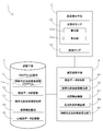
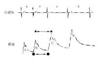
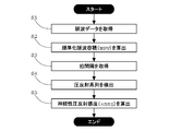
- FIG. 1 It is a block diagram which shows one Embodiment of the neural baroreflex sensitivity measuring apparatus and neural baroreflex sensitivity measuring program which concern on this invention. It is a figure explaining "beat interval” and "beat interval corresponding to pulse wave data" concerning the present invention. It is a flowchart figure which shows one Embodiment of the neural baroreflex sensitivity measuring method which concerns on this invention.
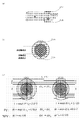
- A The figure which shows a mode that the photoelectric volume pulse wave of a finger artery is measured,
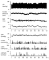
- A Measured data of integrated baroreflex sensitivity (Int BRS), systolic blood pressure (SBP), heart rate interval (RRI), normalized pulse wave volume (NPV) and neural baroreflex sensitivity (nBRS),
- FIG. 8 is a scatter diagram in the baroreflex series of FIG.
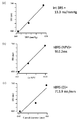
- Example 7 (a) integrated baroreflex sensitivity (Int BRS), (b) neural baroreflex sensitivity (nBRS (NPV)) according to the present invention, and (c) echo method. It is a figure which shows neural baroreflex sensitivity (nBRS (D)).
- nBRS neural baroreflex sensitivity
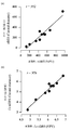
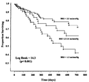
- Example 2 (a) a graph showing the correlation between the neural baroreflex sensitivity (nBRS (NPV)) according to the present invention and the neural baroreflex sensitivity (nBRS (Carotid diameter)) by the echo method; b) It is a graph which shows the correlation of both natural logarithms (Ln). It is a graph which shows the future survival rate by the difference in baroreflex sensitivity in the patient of chronic heart failure.
- the neural baroreflex sensitivity measuring apparatus, the neural baroreflex sensitivity measuring program, and the neural baroreflex sensitivity measuring method according to the present invention include a neural baroreflex sensitivity (neural baroreflex sensitivity) that is a baroreflex sensitivity independent of blood vessel hardness. : NBRS).
- the inventor of the present application has proposed the amplitude of the alternating current component of the pulse wave in the finger arteries at the same time as proposed in Japanese Patent No. 5039123, instead of the carotid artery blood vessel diameter in the echo method described above.
- NPV Normalized Pulse Volume
- a neural baroreflexivity measuring apparatus 1 mainly includes a pulse wave detecting means 2 for detecting a pulse wave of an artery, and a neural baroreflexivity measuring program according to this embodiment.
- the storage unit 3 stores 1a and various types of data, and the arithmetic processing unit 4 controls each of these constituent units and acquires various types of data to execute arithmetic processing.
- each component will be described in detail.
- the pulse wave detection means 2 detects a volume pulse wave indicating a volume change in the artery.
- the pulse wave detection means 2 includes a photoelectric sensor 21 that detects the amount of light, and a pulse wave amplifier 22 that amplifies an output signal from the photoelectric sensor 21 and outputs the amplified signal as pulse wave data.
- the photoelectric sensor 21 includes a light emitting unit 21a such as an LED (Light Emitting Diode) fixed to a fingernail, and a light receiving unit 21b such as a photodiode disposed on the stomach side of the finger at a position facing the light emitting unit 21a.
- the transmitted light amount emitted from the light emitting unit 21a and transmitted through the finger is detected by the light receiving unit 21b.
- the pulse wave amplifier 22 outputs amplified pulse wave data in time series.
- photoelectric volume pulse wave data is detected as pulse wave data.
- a finger artery is used as a detection target portion of pulse wave data, but the present invention is not limited to this. That is, as long as the pulse wave detecting means 2 can detect the pulse wave of the artery, the ear, nose, palm, wrist, arm, foot, and the like can be set as the detection target part.
- the pulse wave detection means 2 is not limited to the above-described configuration, and may be any device that can detect a pulse wave of an artery.
- a wearable pulse wave sensor such as an earphone / earring type that can be attached to an ear, a bracelet type that can be attached to a wrist or an upper arm, a ring type that can be attached to a finger, or the like may be used. If such a pulse wave detection means 2 is used, the load at the time of wearing is small, and detection in daily life is also possible.
- the storage unit 3 stores various data and functions as a working area when the arithmetic processing unit 4 performs arithmetic processing.
- the storage means 3 is composed of a hard disk, ROM (Read Only Memory), RAM (Random Access Memory), flash memory, and the like, and as shown in FIG.
- a program storage unit 31 for storing the sensitivity measurement program 1a, a pulse wave data storage unit 32, a normalized pulse wave volume storage unit 33, a pulse interval storage unit 34, and an electrocardiogram data storage unit 35 are provided.
- the program storage unit 31 is installed with the neural baroreflex sensitivity measurement program 1a of this embodiment.
- the neural baroreflex sensitivity measurement program 1a is executed by the arithmetic processing means 4 so that a computer such as a personal computer or a smartphone functions as each component described later.
- the usage form of the neural baroreflex sensitivity measurement program 1a is not limited to the above configuration.
- the neural baroreflex sensitivity measurement program 1a may be stored in a computer-readable recording medium such as a CD-ROM or DVD-ROM, and read directly from the recording medium and executed.
- the pulse wave data storage unit 32 stores the pulse wave data detected by the pulse wave detection means 2.
- the standardized pulse wave volume storage unit 33 stores the standardized pulse wave volume calculated by the standardized pulse wave volume calculation unit 42 described later.
- the beat interval storage unit 34 stores the beat interval acquired by the beat interval acquisition unit 43 described later.
- the electrocardiogram data storage unit 35 stores electrocardiogram data obtained by electrocardiogram acquisition means (not shown) such as an electrocardiograph.
- the arithmetic processing means 4 is composed of a CPU (Central Processing ⁇ Unit) and the like, and by executing the neural baroreflex sensitivity measurement program 1a, a pulse wave data acquisition unit 41, a normalized pulse wave volume calculation unit 42, The pulse interval acquisition unit 43, the baroreflex detection unit 44, and the neural baroreflex sensitivity calculation unit 45 function.
- a CPU Central Processing ⁇ Unit
- the pulse interval acquisition unit 43, the baroreflex detection unit 44, and the neural baroreflex sensitivity calculation unit 45 function.
- each component will be described in more detail.
- the pulse wave data acquisition unit 41 acquires the pulse wave data of the artery detected by the pulse wave detection means 2 and stores it in the pulse wave data storage unit 32 in time series.
- the pulse wave data acquisition unit 41 acquires pulse wave data directly from the pulse wave detection means 2, but is not limited to this configuration.
- pulse wave data measured by another device may be downloaded via the Internet, or may be taken into the pulse wave data storage unit 32 from a recording medium such as a USB memory.
- the standardized pulse wave volume calculation unit 42 calculates the standardized pulse wave volume (NPV) described above.
- the transmitted light amount ( ⁇ I) corresponding to the pulsation change is determined by the amplitude of the AC component of the pulse wave.
- the transmitted light amount (I) of the pulse wave detection target part (tissue + blood) is determined by the average value of the DC component of the pulse wave at the same time. Therefore, the normalized pulse wave volume calculation unit 42 divides the amplitude of the AC component of the pulse wave by the average value of the DC component of the pulse wave at the same time based on the pulse wave data stored in the pulse wave data storage unit 32. By doing so, the normalized pulse wave volume is calculated for each beat.
- the beat interval acquisition unit 43 acquires a beat interval corresponding to the pulse wave data.
- the “beat interval” means, as shown in FIG. 2, the pulse interval in the pulse wave data (interval between ⁇ marks in FIG. 2), the interval of the portion where the alternating current component of the pulse wave data rises ( 2 is a concept including all time intervals corresponding to one beat, such as an interval between ⁇ marks in FIG. 2 (hereinafter referred to as “rise interval”) and a heartbeat interval (RR interval) in electrocardiogram data. is there.
- the “beat interval corresponding to pulse wave data” means not only the pulse interval in the same time zone as the pulse wave data is acquired but also the time zone in which the pulse wave data is acquired. It is a concept that includes a beat interval delayed by one beat. Specifically, when the beat interval is a heartbeat interval, not only the heartbeat intervals a, b, and c but also the heartbeat intervals b, c, and d are applied to the pulse waves A, B, and C as shown in FIG. Corresponds to “beat interval corresponding to pulse wave data”.
- the pulse interval acquisition unit 43 refers to the pulse wave data stored in the pulse wave data storage unit 32 and acquires the pulse interval and the rising interval corresponding to the pulse wave data in time series.
- electrocardiogram data is separately prepared in the electrocardiogram data storage unit 35 when measuring an elderly person whose pulse interval and rise interval are difficult to discriminate.
- the beat interval acquisition unit 43 refers to the electrocardiogram data and acquires heartbeat intervals corresponding to the pulse wave data in time series.
- the baroreflex detection unit 44 detects baroreflexes that are not affected by the sympathetic nervous system of blood vessels. Specifically, the baroreflex detection unit 44 refers to the normalized pulse wave volume in the normalized pulse wave volume storage unit 33 and the beat interval in the pulse interval storage unit 34, and normalizes the pulse wave volume and the pulse rate. An ascending series in which the interval increases continuously for 3 beats or more, or a descending series in which both the normalized pulse wave volume and the beat interval decrease continuously for 3 beats or more is detected as a baroreflex series. ing.
- the neural baroreflex sensitivity calculation unit 45 calculates the neural baroreflex sensitivity, which is an index indicating the neural baroreflex function.
- the neural baroreflex sensitivity calculation unit 45 acquires data of the baroreflex sequence detected by the baroreflex sequence detector 44 and correlates the normalized pulse wave volume and the pulse interval in the baroreflex sequence. Is calculated as the neural baroreflex sensitivity.
- the neural baroreflex sensitivity measuring apparatus 1 is configured by a personal computer including the storage unit 3 and the arithmetic processing unit 4, and the pulse wave detection unit 2 is separately connected as a peripheral device.
- the apparatus configuration is not limited to the above.
- the neural baroreflex sensitivity measurement program 1a of the present embodiment is converted into an application and installed in a smartphone, and the smartphone is used to measure the neural baroreflex sensitivity measurement of the present embodiment. It is also possible to function as the device 1.
- the pulse wave data acquisition unit 41 acquires pulse wave data (step S1: pulse wave data acquisition step).
- the normalized pulse wave volume calculation unit 42 divides the amplitude of the alternating current component of the pulse wave by the average value of the direct current component of the pulse wave at the same time on the basis of the pulse wave data acquired in step S1.
- the normalized pulse wave volume is calculated for each beat (step S2: normalized pulse wave volume calculating step).
- step S3 beat interval obtaining step
- step S4 baroreflex sequence detection step
- the inventor of the present application excludes the influence of the sympathetic nervous system in a series opposite to the above series, that is, a series in which both the normalized pulse wave volume and the beat interval continuously increase or decrease. It was found that this was the baroreflex series according to the present invention.
- the reason why the number of consecutive beats detected as the baroreflex sequence is 3 beats or more is to ensure the reliability that the sympathetic nervous system is not affected.
- the neural baroreflex sensitivity calculation unit 45 shows the correlation between the normalized pulse wave volume and the pulse interval in the baroreflex sequence based on the baroreflex sequence data detected by the baroreflex sequence detector 44.
- the slope of the regression line is calculated as the neural baroreflex sensitivity (step S5).
- the following effects can be obtained. 1. Without using blood pressure or pulsation changes of the blood vessel diameter in the carotid artery, it is possible to measure the neural baroreflex sensitivity that is simple and objective, independent of the stiffness of the blood vessel. 2. It is not affected by the sympathetic nervous system in the artery, and can measure the highly reliable neural baroreflex sensitivity. 3. By using normalized pulse wave volume, which is a dimensionless absolute quantity, errors due to tissue components are excluded, and comparisons between individuals as well as comparisons with the same subject are possible. The trend of neural baroreflex sensitivity can be grasped. 4).
- the parasympathetic nervous system index can be acquired from the baroreflex series, and the sympathetic nervous system index can be acquired from a series other than the baroreflex series. 5.
- electrocardiogram data it is possible to acquire an accurate beat interval even from a subject who cannot easily read the beat interval in the pulse wave.
- Example 1 an experiment was conducted to confirm whether or not a baroreflex series that is not affected by the sympathetic nerve actually exists in the finger artery from which the pulse wave data is acquired.
- blood pressure monitor (device name: MUB101, manufacturer: Medisense, Inc.), electrocardiogram detection means (device name: LRR-03, manufacturer: GM S) and pulse wave detection means 2 (device name: MPN1001, manufacturer: Medisense Corporation) were mounted, and blood pressure (AP), heart rate interval (RRI) and pulse wave data were measured in chronological order for 540 seconds.
- AP blood pressure
- RRI heart rate interval
- pulse wave data were measured in chronological order for 540 seconds.
- an ultrasonic probe (device name: UNEXEF38G, manufacturer: Yunex Co., Ltd.) was fixed on the neck of the subject, and the diameter change (Carotid Diameter) in the carotid artery was measured.
- UNEXX EF device name: UNEXEF38G, manufacturer: UNEX Corporation
- Int BRS integrated baroreflex sensitivity
- the neural baroreflex sensitivity (nBRS (NPV)) according to the present invention and the neural baroreflex sensitivity (nBRS (D)) by the conventional echo method were calculated. The result is shown in FIG.
- FIG. 7 is a graph obtained by extracting an example of the baroreflex sequence about 80 seconds from the start of measurement in the actually measured data in FIG.
- FIG. 8 is a scatter diagram in the baroreflex sequence of FIG. 7, (a) integrated baroreflex sensitivity (Int BRS) by sequence method, (b) neural baroreflex sensitivity (nBRS (NPV) according to the present invention). And (c) Neural baroreflex sensitivity (nBRS (D)) by echo method.
- Int BRS integrated baroreflex sensitivity
- nBRS neural baroreflex sensitivity
- D Neural baroreflex sensitivity
- FIGS. 6 to 8 it is shown that there are more baroreflex sequences according to the present invention in size and frequency than the baroreflex sequences in the conventional sequence method and the baroreflex sequences by the echo method. It was done.
- the baroreflex series according to the present invention that is, the normalized pulse wave volume and the pulse interval both increase or decrease continuously for 3 beats or more. It was demonstrated that there are baroreflex series that are not affected by sympathetic nerves.
- Example 2 in the measured data of Example 1 shown in FIG. 6, the neural baroreflex sensitivity (nBRS (NPV)) according to the present invention and the neural baroreflex sensitivity (nBRS (Carotid diameter)) by the echo method are used.
- nBRS neural baroreflex sensitivity
- nBRS Carotid diameter
- FIG. 9A is a graph showing the correlation between the neural baroreflex sensitivity according to the present invention and the neural baroreflex sensitivity by the echo method
- FIG. 9B shows the natural logarithm (Ln) of both. It is a graph which shows a correlation.
- the correlation coefficient r in FIG. 9A was 0.952
- the correlation coefficient r in FIG. 9B was 0.976. That is, in any graph, a high correlation was recognized between the neural baroreflex sensitivity according to the present invention and the neural baroreflex sensitivity by the echo method.
- the neural baroreflex sensitivity measuring apparatus 1, the neural baroreflex sensitivity measurement program 1a, and the neural baroreflex sensitivity measuring method according to the present invention are not limited to the above-described embodiments and examples, and may be changed as appropriate. can do.
- a display table (e.g., good, normal, bad) indicating the sensitivity of the baroreflex function is stored in the storage means 3 in correspondence with the numerical range of the neural baroreflex sensitivity, and the neural baroreflex sensitivity is stored. Based on the value of the neural baroreflex sensitivity calculated by the calculation unit 45, an evaluation regarding the sensitivity of the baroreflex function may be output from the display unit or the print unit and presented to the subject.
- the neural baroreflex sensitivity measuring apparatus 1 can be miniaturized to the size of a mobile terminal such as a smartphone, it can be used as a health device that can be easily handled from children to the elderly. It can also be widely spread for use.
- Neural baroreflex sensitivity measuring apparatus 1a Nervous baroreflex sensitivity measurement program 2 Pulse wave detection means 3 Storage means 4 Arithmetic processing means 21 Photoelectric sensor 21a Light emission part 21b Light reception part 22 Pulse wave amplifier 31 Program memory part 32 Pulse wave data Storage unit 33 Normalized pulse wave volume storage unit 34 Beat interval storage unit 35 Electrocardiogram data storage unit 41 Pulse wave data acquisition unit 42 Normalized pulse wave volume calculation unit 43 Beat interval acquisition unit 44 Baroreflex series detection unit 45 Nervous baroreflex Sensitivity calculator
Landscapes
- Health & Medical Sciences (AREA)
- Life Sciences & Earth Sciences (AREA)
- Engineering & Computer Science (AREA)
- Public Health (AREA)
- Molecular Biology (AREA)
- Veterinary Medicine (AREA)
- General Health & Medical Sciences (AREA)
- Physics & Mathematics (AREA)
- Animal Behavior & Ethology (AREA)
- Biophysics (AREA)
- Pathology (AREA)
- Biomedical Technology (AREA)
- Heart & Thoracic Surgery (AREA)
- Medical Informatics (AREA)
- Physiology (AREA)
- Surgery (AREA)
- Cardiology (AREA)
- Neurology (AREA)
- Computer Vision & Pattern Recognition (AREA)
- Signal Processing (AREA)
- Artificial Intelligence (AREA)
- Psychiatry (AREA)
- Neurosurgery (AREA)
- Hematology (AREA)
- Vascular Medicine (AREA)
- Measuring Pulse, Heart Rate, Blood Pressure Or Blood Flow (AREA)
- Measurement And Recording Of Electrical Phenomena And Electrical Characteristics Of The Living Body (AREA)
Abstract
Description
I/I0=exp(-εCD) ・・・式(1)
1.血圧や頸動脈における血管径の脈動変化を用いることなく、簡易的かつ客観的に、血管の硬さに依存しない神経性圧反射感度を測定することができる。
2.動脈における交感神経系の影響を受けておらず、信頼性の高い神経性圧反射感度を測定することができる。
3.無次元の絶対量である規準化脈波容積を用いることにより、組織成分に起因する誤差を除外し、同一被験者についての比較のみならず個人間での比較が可能となるため、広く一般的に神経性圧反射感度の動向を把握することができる。
4.圧反射系列からは副交感神経系の指標を取得できるとともに、圧反射系列以外の系列からは、交感神経系の指標を取得することができる。
5.心電図データを用いることにより、脈波における拍間隔が読み取りにくい被験者からも正確な拍間隔を取得することができる。
1a 神経性圧反射感度測定プログラム
2 脈波検出手段
3 記憶手段
4 演算処理手段
21 光電式センサ
21a 発光部
21b 受光部
22 脈波アンプ
31 プログラム記憶部
32 脈波データ記憶部
33 規準化脈波容積記憶部
34 拍間隔記憶部
35 心電図データ記憶部
41 脈波データ取得部
42 規準化脈波容積算出部
43 拍間隔取得部
44 圧反射系列検出部
45 神経性圧反射感度算出部
Claims (3)
- 動脈の脈波データを取得する脈波データ取得部と、
前記脈波データに基づいて、脈波の交流成分の振幅を同時刻における当該脈波の直流成分の平均値で除算してなる規準化脈波容積を算出する規準化脈波容積算出部と、
前記脈波データに対応する拍間隔を取得する拍間隔取得部と、
前記規準化脈波容積および前記拍間隔がいずれも3拍以上連続して増加または減少する圧反射系列を検出する圧反射系列検出部と、
前記圧反射系列における前記規準化脈波容積と前記拍間隔との相関を示す回帰直線の傾きを神経性の圧反射機能を示す指標である神経性圧反射感度として算出する神経性圧反射感度算出部と
を有する神経性圧反射感度測定装置。 - 動脈の脈波データを取得する脈波データ取得部と、
前記脈波データに基づいて、脈波の交流成分の振幅を同時刻における当該脈波の直流成分の平均値で除算してなる規準化脈波容積を算出する規準化脈波容積算出部と、
前記脈波データに対応する拍間隔を取得する拍間隔取得部と、
前記規準化脈波容積および前記拍間隔がいずれも3拍以上連続して増加または減少する圧反射系列を検出する圧反射系列検出部と、
前記圧反射系列における前記規準化脈波容積と前記拍間隔との相関を示す回帰直線の傾きを神経性の圧反射機能を示す指標である神経性圧反射感度として算出する神経性圧反射感度算出部と
してコンピュータを機能させる神経性圧反射感度測定プログラム。 - 動脈の脈波データを取得する脈波データ取得ステップと、
前記脈波データに基づいて、脈波の交流成分の振幅を同時刻における当該脈波の直流成分の平均値で除算してなる規準化脈波容積を算出する規準化脈波容積算出ステップと、
前記脈波データに対応する拍間隔を取得する拍間隔取得ステップと、
前記規準化脈波容積および前記拍間隔がいずれも3拍以上連続して増加または減少する圧反射系列を検出する圧反射系列検出ステップと、
前記圧反射系列における前記規準化脈波容積と前記拍間隔との相関を示す回帰直線の傾きを神経性の圧反射機能を示す指標である神経性圧反射感度として算出する神経性圧反射感度算出ステップと
を有する神経性圧反射感度測定方法。
Priority Applications (3)
| Application Number | Priority Date | Filing Date | Title |
|---|---|---|---|
| EP14773453.7A EP2979632B1 (en) | 2013-03-29 | 2014-03-28 | Neurogenic baroreflex sensitivity measurement device, neurogenic baroreflex sensitivity measurement program and neurogenic baroreflex sensitivity measurement method |
| JP2015508749A JP6297539B2 (ja) | 2013-03-29 | 2014-03-28 | 神経性圧反射感度測定装置、神経性圧反射感度測定プログラムおよび神経性圧反射感度測定方法 |
| US14/775,827 US9826909B2 (en) | 2013-03-29 | 2014-03-28 | Neurogenic baroreflex sensitivity measurement device, neurogenic baroreflex sensitivity measurement program and neurogenic baroreflex sensitivity measurement method |
Applications Claiming Priority (2)
| Application Number | Priority Date | Filing Date | Title |
|---|---|---|---|
| JP2013-074027 | 2013-03-29 | ||
| JP2013074027 | 2013-03-29 |
Publications (1)
| Publication Number | Publication Date |
|---|---|
| WO2014157605A1 true WO2014157605A1 (ja) | 2014-10-02 |
Family
ID=51624561
Family Applications (1)
| Application Number | Title | Priority Date | Filing Date |
|---|---|---|---|
| PCT/JP2014/059081 Ceased WO2014157605A1 (ja) | 2013-03-29 | 2014-03-28 | 神経性圧反射感度測定装置、神経性圧反射感度測定プログラムおよび神経性圧反射感度測定方法 |
Country Status (4)
| Country | Link |
|---|---|
| US (1) | US9826909B2 (ja) |
| EP (1) | EP2979632B1 (ja) |
| JP (1) | JP6297539B2 (ja) |
| WO (1) | WO2014157605A1 (ja) |
Cited By (2)
| Publication number | Priority date | Publication date | Assignee | Title |
|---|---|---|---|---|
| JP2017213123A (ja) * | 2016-05-31 | 2017-12-07 | 日本電信電話株式会社 | 血流量測定装置および血流量測定方法 |
| WO2018181851A1 (ja) | 2017-03-30 | 2018-10-04 | 北海道公立大学法人札幌医科大学 | 圧反射性血管交感神経活動検出装置、圧反射性血管交感神経活動検出プログラムおよび圧反射性血管交感神経活動検出方法 |
Families Citing this family (1)
| Publication number | Priority date | Publication date | Assignee | Title |
|---|---|---|---|---|
| US20210393188A1 (en) * | 2020-06-19 | 2021-12-23 | The Regents Of The University Of Michigan | Quantification of intermittent function of baroreflex from continuous arterial pressure data |
Citations (4)
| Publication number | Priority date | Publication date | Assignee | Title |
|---|---|---|---|---|
| JP2004041244A (ja) * | 2002-05-14 | 2004-02-12 | Nippon Colin Co Ltd | 血管内皮機能評価装置 |
| JP2008086568A (ja) | 2006-10-02 | 2008-04-17 | Fukuda Denshi Co Ltd | 血圧反射機能測定装置 |
| WO2008105229A1 (ja) * | 2007-02-28 | 2008-09-04 | Sapporo Medical University | 指動脈弾力性測定プログラム、指動脈弾力性測定装置および指動脈弾力性測定方法 |
| JP2011189080A (ja) * | 2010-03-16 | 2011-09-29 | Toyama Univ | 指尖脈波解析装置及びこれを用いた血管内皮機能評価システム |
Family Cites Families (4)
| Publication number | Priority date | Publication date | Assignee | Title |
|---|---|---|---|---|
| US6616613B1 (en) * | 2000-04-27 | 2003-09-09 | Vitalsines International, Inc. | Physiological signal monitoring system |
| US8672852B2 (en) * | 2002-12-13 | 2014-03-18 | Intercure Ltd. | Apparatus and method for beneficial modification of biorhythmic activity |
| AU2004203059A1 (en) * | 2004-06-08 | 2005-12-22 | The Government Of The United States Of America As Represented By The Secretary Of The Department Of Health And Human Services, Centers For Disease Control And Prevention | Apparatus and method for assessing peripheral circulation to evaluate a physiological condition |
| US20090124914A1 (en) * | 2007-11-08 | 2009-05-14 | Kuo Terry B J | Analysis system and a method for pulse diagnosis in chinese medicine |
-
2014
- 2014-03-28 EP EP14773453.7A patent/EP2979632B1/en active Active
- 2014-03-28 US US14/775,827 patent/US9826909B2/en active Active
- 2014-03-28 WO PCT/JP2014/059081 patent/WO2014157605A1/ja not_active Ceased
- 2014-03-28 JP JP2015508749A patent/JP6297539B2/ja active Active
Patent Citations (5)
| Publication number | Priority date | Publication date | Assignee | Title |
|---|---|---|---|---|
| JP2004041244A (ja) * | 2002-05-14 | 2004-02-12 | Nippon Colin Co Ltd | 血管内皮機能評価装置 |
| JP2008086568A (ja) | 2006-10-02 | 2008-04-17 | Fukuda Denshi Co Ltd | 血圧反射機能測定装置 |
| WO2008105229A1 (ja) * | 2007-02-28 | 2008-09-04 | Sapporo Medical University | 指動脈弾力性測定プログラム、指動脈弾力性測定装置および指動脈弾力性測定方法 |
| JP5039123B2 (ja) | 2007-02-28 | 2012-10-03 | 北海道公立大学法人 札幌医科大学 | 指動脈弾力性測定プログラム、指動脈弾力性測定装置および指動脈弾力性測定方法 |
| JP2011189080A (ja) * | 2010-03-16 | 2011-09-29 | Toyama Univ | 指尖脈波解析装置及びこれを用いた血管内皮機能評価システム |
Non-Patent Citations (3)
| Title |
|---|
| BRIAN E. HUNT ET AL.: "Quantification of Mechanical and Neural Components of Vagal Baroreflex in Humans", HYPERTENSION, vol. 37, no. ISSUE., 2001, pages 1362 - 1368, XP055283384 * |
| BRIAN E. HUNT ET AL.: "Quantification of Mechanical and Neural Components of Vagal Baroreflex in Humans, Hypertension", vol. 37, 2001, AMERICAN HEART ASSOCIATION, pages: 1362 - 1368 |
| MASASHI ICHINOSE ET AL.: "Modulation of arterial baroreflex dynamic response during mild orthostatic stress in humans", THE JOURNAL OF PHYSIOLOGY, vol. 557, no. ISSUE., 2004, pages 321 - 330, XP055283385 * |
Cited By (5)
| Publication number | Priority date | Publication date | Assignee | Title |
|---|---|---|---|---|
| JP2017213123A (ja) * | 2016-05-31 | 2017-12-07 | 日本電信電話株式会社 | 血流量測定装置および血流量測定方法 |
| WO2018181851A1 (ja) | 2017-03-30 | 2018-10-04 | 北海道公立大学法人札幌医科大学 | 圧反射性血管交感神経活動検出装置、圧反射性血管交感神経活動検出プログラムおよび圧反射性血管交感神経活動検出方法 |
| JPWO2018181851A1 (ja) * | 2017-03-30 | 2020-02-20 | 北海道公立大学法人 札幌医科大学 | 圧反射性血管交感神経活動検出装置、圧反射性血管交感神経活動検出プログラムおよび圧反射性血管交感神経活動検出方法 |
| JP7081831B2 (ja) | 2017-03-30 | 2022-06-07 | 北海道公立大学法人 札幌医科大学 | 圧反射性血管交感神経活動検出装置、圧反射性血管交感神経活動検出プログラムおよび圧反射性血管交感神経活動検出方法 |
| US11517207B2 (en) | 2017-03-30 | 2022-12-06 | Sapporo Medical University | Baroreflex vascular sympathetic nervous activity detection device, baroreflex vascular sympathetic nervous activity detection program, and baroreflex vascular sympathetic nervous activity detection method |
Also Published As
| Publication number | Publication date |
|---|---|
| EP2979632B1 (en) | 2020-12-16 |
| EP2979632A1 (en) | 2016-02-03 |
| JPWO2014157605A1 (ja) | 2017-02-16 |
| JP6297539B2 (ja) | 2018-03-20 |
| US20160029909A1 (en) | 2016-02-04 |
| US9826909B2 (en) | 2017-11-28 |
| EP2979632A4 (en) | 2016-12-07 |
Similar Documents
| Publication | Publication Date | Title |
|---|---|---|
| Etemadi et al. | Wearable ballistocardiogram and seismocardiogram systems for health and performance | |
| US20180199824A1 (en) | Device for measuring biological signals | |
| JP5408751B2 (ja) | 自律神経機能測定装置 | |
| US20160270708A1 (en) | Bio-information measurement device and method therefor | |
| US20130018272A1 (en) | Pulse wave velocity measurement device, pulse wave velocity measurement method and pulse wave velocity measurement program | |
| JPWO2014208289A1 (ja) | 生体状態推定装置 | |
| JP2023532319A (ja) | 末梢動脈緊張の評価を補償する装置及び方法 | |
| KR20170109554A (ko) | 대상자의 정신 상태를 도출하기 위한 방법 및 장치 | |
| JP6203737B2 (ja) | 指細小動脈拡張能検査方法、指細小動脈拡張能検査装置および指細小動脈拡張能検査プログラム | |
| CN107920786A (zh) | 脉搏血氧测定 | |
| US20210169406A1 (en) | Apparatus for determining a stress and/or pain level | |
| Fischer et al. | Continuous non-invasive determination of nocturnal blood pressure variation using photoplethysmographic pulse wave signals: comparison of pulse propagation time, pulse transit time and RR-interval | |
| JP2018153250A (ja) | 血圧測定装置、方法及びプログラム | |
| JP6297539B2 (ja) | 神経性圧反射感度測定装置、神経性圧反射感度測定プログラムおよび神経性圧反射感度測定方法 | |
| Zhang et al. | The effect of local mild cold exposure on pulse transit time | |
| JP7081831B2 (ja) | 圧反射性血管交感神経活動検出装置、圧反射性血管交感神経活動検出プログラムおよび圧反射性血管交感神経活動検出方法 | |
| US12364405B1 (en) | Hemodynamic determination of arterial stiffness, arterial age, arterial deposits and HBA1C | |
| JP7261491B2 (ja) | 生体情報測定装置 | |
| JP6850493B2 (ja) | 指細小動脈拡張能連続検査プログラム、指細小動脈拡張能連続検査装置および指細小動脈拡張能連続検査方法 | |
| JP7675335B2 (ja) | 血行動態推定方法 | |
| JP2018068556A (ja) | 胸腔内圧推定装置 | |
| JP7735748B2 (ja) | 生体情報測定装置、及び生体情報測定プログラム | |
| TW201106920A (en) | Computer system for acquiring physiological information | |
| US20170049404A1 (en) | Wearable LED Sensor Device Configured to Identify a Wearer's Pulse | |
| JP4453431B2 (ja) | 生体情報測定装置 |
Legal Events
| Date | Code | Title | Description |
|---|---|---|---|
| 121 | Ep: the epo has been informed by wipo that ep was designated in this application |
Ref document number: 14773453 Country of ref document: EP Kind code of ref document: A1 |
|
| ENP | Entry into the national phase |
Ref document number: 2015508749 Country of ref document: JP Kind code of ref document: A |
|
| WWE | Wipo information: entry into national phase |
Ref document number: 14775827 Country of ref document: US |
|
| NENP | Non-entry into the national phase |
Ref country code: DE |
|
| WWE | Wipo information: entry into national phase |
Ref document number: 2014773453 Country of ref document: EP |