WO2014162597A1 - 内燃機関の排気浄化システム - Google Patents
内燃機関の排気浄化システム Download PDFInfo
- Publication number
- WO2014162597A1 WO2014162597A1 PCT/JP2013/060512 JP2013060512W WO2014162597A1 WO 2014162597 A1 WO2014162597 A1 WO 2014162597A1 JP 2013060512 W JP2013060512 W JP 2013060512W WO 2014162597 A1 WO2014162597 A1 WO 2014162597A1
- Authority
- WO
- WIPO (PCT)
- Prior art keywords
- ammonia
- supply
- unit
- fuel component
- fuel
- Prior art date
- Legal status (The legal status is an assumption and is not a legal conclusion. Google has not performed a legal analysis and makes no representation as to the accuracy of the status listed.)
- Ceased
Links
Images


Classifications
-
- F—MECHANICAL ENGINEERING; LIGHTING; HEATING; WEAPONS; BLASTING
- F01—MACHINES OR ENGINES IN GENERAL; ENGINE PLANTS IN GENERAL; STEAM ENGINES
- F01N—GAS-FLOW SILENCERS OR EXHAUST APPARATUS FOR MACHINES OR ENGINES IN GENERAL; GAS-FLOW SILENCERS OR EXHAUST APPARATUS FOR INTERNAL-COMBUSTION ENGINES
- F01N3/00—Exhaust or silencing apparatus having means for purifying, rendering innocuous, or otherwise treating exhaust
- F01N3/08—Exhaust or silencing apparatus having means for purifying, rendering innocuous, or otherwise treating exhaust for rendering innocuous
- F01N3/10—Exhaust or silencing apparatus having means for purifying, rendering innocuous, or otherwise treating exhaust for rendering innocuous by thermal or catalytic conversion of noxious components of exhaust
- F01N3/18—Exhaust or silencing apparatus having means for purifying, rendering innocuous, or otherwise treating exhaust for rendering innocuous by thermal or catalytic conversion of noxious components of exhaust characterised by methods of operation; Control
- F01N3/20—Exhaust or silencing apparatus having means for purifying, rendering innocuous, or otherwise treating exhaust for rendering innocuous by thermal or catalytic conversion of noxious components of exhaust characterised by methods of operation; Control specially adapted for catalytic conversion
- F01N3/206—Adding periodically or continuously substances to exhaust gases for promoting purification, e.g. catalytic material in liquid form, NOx reducing agents
- F01N3/208—Control of selective catalytic reduction [SCR], e.g. by adjusting the dosing of reducing agent
-
- B—PERFORMING OPERATIONS; TRANSPORTING
- B01—PHYSICAL OR CHEMICAL PROCESSES OR APPARATUS IN GENERAL
- B01D—SEPARATION
- B01D53/00—Separation of gases or vapours; Recovering vapours of volatile solvents from gases; Chemical or biological purification of waste gases, e.g. engine exhaust gases, smoke, fumes, flue gases, aerosols
- B01D53/34—Chemical or biological purification of waste gases
- B01D53/92—Chemical or biological purification of waste gases of engine exhaust gases
- B01D53/94—Chemical or biological purification of waste gases of engine exhaust gases by catalytic processes
- B01D53/9404—Removing only nitrogen compounds
- B01D53/9409—Nitrogen oxides
- B01D53/9431—Processes characterised by a specific device
-
- B—PERFORMING OPERATIONS; TRANSPORTING
- B01—PHYSICAL OR CHEMICAL PROCESSES OR APPARATUS IN GENERAL
- B01D—SEPARATION
- B01D53/00—Separation of gases or vapours; Recovering vapours of volatile solvents from gases; Chemical or biological purification of waste gases, e.g. engine exhaust gases, smoke, fumes, flue gases, aerosols
- B01D53/34—Chemical or biological purification of waste gases
- B01D53/92—Chemical or biological purification of waste gases of engine exhaust gases
- B01D53/94—Chemical or biological purification of waste gases of engine exhaust gases by catalytic processes
- B01D53/9495—Controlling the catalytic process
-
- F—MECHANICAL ENGINEERING; LIGHTING; HEATING; WEAPONS; BLASTING
- F01—MACHINES OR ENGINES IN GENERAL; ENGINE PLANTS IN GENERAL; STEAM ENGINES
- F01N—GAS-FLOW SILENCERS OR EXHAUST APPARATUS FOR MACHINES OR ENGINES IN GENERAL; GAS-FLOW SILENCERS OR EXHAUST APPARATUS FOR INTERNAL-COMBUSTION ENGINES
- F01N11/00—Monitoring or diagnostic devices for exhaust-gas treatment apparatus
- F01N11/002—Monitoring or diagnostic devices for exhaust-gas treatment apparatus the diagnostic devices measuring or estimating temperature or pressure in, or downstream of the exhaust apparatus
-
- F—MECHANICAL ENGINEERING; LIGHTING; HEATING; WEAPONS; BLASTING
- F01—MACHINES OR ENGINES IN GENERAL; ENGINE PLANTS IN GENERAL; STEAM ENGINES
- F01N—GAS-FLOW SILENCERS OR EXHAUST APPARATUS FOR MACHINES OR ENGINES IN GENERAL; GAS-FLOW SILENCERS OR EXHAUST APPARATUS FOR INTERNAL-COMBUSTION ENGINES
- F01N13/00—Exhaust or silencing apparatus characterised by constructional features
- F01N13/009—Exhaust or silencing apparatus characterised by constructional features having two or more separate purifying devices arranged in series
-
- F—MECHANICAL ENGINEERING; LIGHTING; HEATING; WEAPONS; BLASTING
- F01—MACHINES OR ENGINES IN GENERAL; ENGINE PLANTS IN GENERAL; STEAM ENGINES
- F01N—GAS-FLOW SILENCERS OR EXHAUST APPARATUS FOR MACHINES OR ENGINES IN GENERAL; GAS-FLOW SILENCERS OR EXHAUST APPARATUS FOR INTERNAL-COMBUSTION ENGINES
- F01N3/00—Exhaust or silencing apparatus having means for purifying, rendering innocuous, or otherwise treating exhaust
- F01N3/02—Exhaust or silencing apparatus having means for purifying, rendering innocuous, or otherwise treating exhaust for cooling, or for removing solid constituents of, exhaust
- F01N3/021—Exhaust or silencing apparatus having means for purifying, rendering innocuous, or otherwise treating exhaust for cooling, or for removing solid constituents of, exhaust by means of filters
- F01N3/023—Exhaust or silencing apparatus having means for purifying, rendering innocuous, or otherwise treating exhaust for cooling, or for removing solid constituents of, exhaust by means of filters using means for regenerating the filters, e.g. by burning trapped particles
- F01N3/0231—Exhaust or silencing apparatus having means for purifying, rendering innocuous, or otherwise treating exhaust for cooling, or for removing solid constituents of, exhaust by means of filters using means for regenerating the filters, e.g. by burning trapped particles using special exhaust apparatus upstream of the filter for producing nitrogen dioxide, e.g. for continuous filter regeneration systems [CRT]
-
- F—MECHANICAL ENGINEERING; LIGHTING; HEATING; WEAPONS; BLASTING
- F01—MACHINES OR ENGINES IN GENERAL; ENGINE PLANTS IN GENERAL; STEAM ENGINES
- F01N—GAS-FLOW SILENCERS OR EXHAUST APPARATUS FOR MACHINES OR ENGINES IN GENERAL; GAS-FLOW SILENCERS OR EXHAUST APPARATUS FOR INTERNAL-COMBUSTION ENGINES
- F01N3/00—Exhaust or silencing apparatus having means for purifying, rendering innocuous, or otherwise treating exhaust
- F01N3/02—Exhaust or silencing apparatus having means for purifying, rendering innocuous, or otherwise treating exhaust for cooling, or for removing solid constituents of, exhaust
- F01N3/021—Exhaust or silencing apparatus having means for purifying, rendering innocuous, or otherwise treating exhaust for cooling, or for removing solid constituents of, exhaust by means of filters
- F01N3/023—Exhaust or silencing apparatus having means for purifying, rendering innocuous, or otherwise treating exhaust for cooling, or for removing solid constituents of, exhaust by means of filters using means for regenerating the filters, e.g. by burning trapped particles
- F01N3/025—Exhaust or silencing apparatus having means for purifying, rendering innocuous, or otherwise treating exhaust for cooling, or for removing solid constituents of, exhaust by means of filters using means for regenerating the filters, e.g. by burning trapped particles using fuel burner or by adding fuel to exhaust
- F01N3/0253—Exhaust or silencing apparatus having means for purifying, rendering innocuous, or otherwise treating exhaust for cooling, or for removing solid constituents of, exhaust by means of filters using means for regenerating the filters, e.g. by burning trapped particles using fuel burner or by adding fuel to exhaust adding fuel to exhaust gases
-
- F—MECHANICAL ENGINEERING; LIGHTING; HEATING; WEAPONS; BLASTING
- F01—MACHINES OR ENGINES IN GENERAL; ENGINE PLANTS IN GENERAL; STEAM ENGINES
- F01N—GAS-FLOW SILENCERS OR EXHAUST APPARATUS FOR MACHINES OR ENGINES IN GENERAL; GAS-FLOW SILENCERS OR EXHAUST APPARATUS FOR INTERNAL-COMBUSTION ENGINES
- F01N3/00—Exhaust or silencing apparatus having means for purifying, rendering innocuous, or otherwise treating exhaust
- F01N3/02—Exhaust or silencing apparatus having means for purifying, rendering innocuous, or otherwise treating exhaust for cooling, or for removing solid constituents of, exhaust
- F01N3/021—Exhaust or silencing apparatus having means for purifying, rendering innocuous, or otherwise treating exhaust for cooling, or for removing solid constituents of, exhaust by means of filters
- F01N3/033—Exhaust or silencing apparatus having means for purifying, rendering innocuous, or otherwise treating exhaust for cooling, or for removing solid constituents of, exhaust by means of filters in combination with other devices
- F01N3/035—Exhaust or silencing apparatus having means for purifying, rendering innocuous, or otherwise treating exhaust for cooling, or for removing solid constituents of, exhaust by means of filters in combination with other devices with catalytic reactors
-
- F—MECHANICAL ENGINEERING; LIGHTING; HEATING; WEAPONS; BLASTING
- F01—MACHINES OR ENGINES IN GENERAL; ENGINE PLANTS IN GENERAL; STEAM ENGINES
- F01N—GAS-FLOW SILENCERS OR EXHAUST APPARATUS FOR MACHINES OR ENGINES IN GENERAL; GAS-FLOW SILENCERS OR EXHAUST APPARATUS FOR INTERNAL-COMBUSTION ENGINES
- F01N3/00—Exhaust or silencing apparatus having means for purifying, rendering innocuous, or otherwise treating exhaust
- F01N3/08—Exhaust or silencing apparatus having means for purifying, rendering innocuous, or otherwise treating exhaust for rendering innocuous
- F01N3/10—Exhaust or silencing apparatus having means for purifying, rendering innocuous, or otherwise treating exhaust for rendering innocuous by thermal or catalytic conversion of noxious components of exhaust
- F01N3/103—Oxidation catalysts for HC and CO only
-
- F—MECHANICAL ENGINEERING; LIGHTING; HEATING; WEAPONS; BLASTING
- F01—MACHINES OR ENGINES IN GENERAL; ENGINE PLANTS IN GENERAL; STEAM ENGINES
- F01N—GAS-FLOW SILENCERS OR EXHAUST APPARATUS FOR MACHINES OR ENGINES IN GENERAL; GAS-FLOW SILENCERS OR EXHAUST APPARATUS FOR INTERNAL-COMBUSTION ENGINES
- F01N9/00—Electrical control of exhaust gas treating apparatus
-
- F—MECHANICAL ENGINEERING; LIGHTING; HEATING; WEAPONS; BLASTING
- F01—MACHINES OR ENGINES IN GENERAL; ENGINE PLANTS IN GENERAL; STEAM ENGINES
- F01N—GAS-FLOW SILENCERS OR EXHAUST APPARATUS FOR MACHINES OR ENGINES IN GENERAL; GAS-FLOW SILENCERS OR EXHAUST APPARATUS FOR INTERNAL-COMBUSTION ENGINES
- F01N2550/00—Monitoring or diagnosing the deterioration of exhaust systems
- F01N2550/02—Catalytic activity of catalytic converters
-
- F—MECHANICAL ENGINEERING; LIGHTING; HEATING; WEAPONS; BLASTING
- F01—MACHINES OR ENGINES IN GENERAL; ENGINE PLANTS IN GENERAL; STEAM ENGINES
- F01N—GAS-FLOW SILENCERS OR EXHAUST APPARATUS FOR MACHINES OR ENGINES IN GENERAL; GAS-FLOW SILENCERS OR EXHAUST APPARATUS FOR INTERNAL-COMBUSTION ENGINES
- F01N2550/00—Monitoring or diagnosing the deterioration of exhaust systems
- F01N2550/04—Filtering activity of particulate filters
-
- F—MECHANICAL ENGINEERING; LIGHTING; HEATING; WEAPONS; BLASTING
- F01—MACHINES OR ENGINES IN GENERAL; ENGINE PLANTS IN GENERAL; STEAM ENGINES
- F01N—GAS-FLOW SILENCERS OR EXHAUST APPARATUS FOR MACHINES OR ENGINES IN GENERAL; GAS-FLOW SILENCERS OR EXHAUST APPARATUS FOR INTERNAL-COMBUSTION ENGINES
- F01N2610/00—Adding substances to exhaust gases
- F01N2610/02—Adding substances to exhaust gases the substance being ammonia or urea
-
- F—MECHANICAL ENGINEERING; LIGHTING; HEATING; WEAPONS; BLASTING
- F01—MACHINES OR ENGINES IN GENERAL; ENGINE PLANTS IN GENERAL; STEAM ENGINES
- F01N—GAS-FLOW SILENCERS OR EXHAUST APPARATUS FOR MACHINES OR ENGINES IN GENERAL; GAS-FLOW SILENCERS OR EXHAUST APPARATUS FOR INTERNAL-COMBUSTION ENGINES
- F01N2610/00—Adding substances to exhaust gases
- F01N2610/03—Adding substances to exhaust gases the substance being hydrocarbons, e.g. engine fuel
-
- F—MECHANICAL ENGINEERING; LIGHTING; HEATING; WEAPONS; BLASTING
- F01—MACHINES OR ENGINES IN GENERAL; ENGINE PLANTS IN GENERAL; STEAM ENGINES
- F01N—GAS-FLOW SILENCERS OR EXHAUST APPARATUS FOR MACHINES OR ENGINES IN GENERAL; GAS-FLOW SILENCERS OR EXHAUST APPARATUS FOR INTERNAL-COMBUSTION ENGINES
- F01N2900/00—Details of electrical control or of the monitoring of the exhaust gas treating apparatus
- F01N2900/06—Parameters used for exhaust control or diagnosing
- F01N2900/16—Parameters used for exhaust control or diagnosing said parameters being related to the exhaust apparatus, e.g. particulate filter or catalyst
- F01N2900/1618—HC-slip from catalyst
-
- F—MECHANICAL ENGINEERING; LIGHTING; HEATING; WEAPONS; BLASTING
- F01—MACHINES OR ENGINES IN GENERAL; ENGINE PLANTS IN GENERAL; STEAM ENGINES
- F01N—GAS-FLOW SILENCERS OR EXHAUST APPARATUS FOR MACHINES OR ENGINES IN GENERAL; GAS-FLOW SILENCERS OR EXHAUST APPARATUS FOR INTERNAL-COMBUSTION ENGINES
- F01N2900/00—Details of electrical control or of the monitoring of the exhaust gas treating apparatus
- F01N2900/06—Parameters used for exhaust control or diagnosing
- F01N2900/16—Parameters used for exhaust control or diagnosing said parameters being related to the exhaust apparatus, e.g. particulate filter or catalyst
- F01N2900/1621—Catalyst conversion efficiency
-
- Y—GENERAL TAGGING OF NEW TECHNOLOGICAL DEVELOPMENTS; GENERAL TAGGING OF CROSS-SECTIONAL TECHNOLOGIES SPANNING OVER SEVERAL SECTIONS OF THE IPC; TECHNICAL SUBJECTS COVERED BY FORMER USPC CROSS-REFERENCE ART COLLECTIONS [XRACs] AND DIGESTS
- Y02—TECHNOLOGIES OR APPLICATIONS FOR MITIGATION OR ADAPTATION AGAINST CLIMATE CHANGE
- Y02T—CLIMATE CHANGE MITIGATION TECHNOLOGIES RELATED TO TRANSPORTATION
- Y02T10/00—Road transport of goods or passengers
- Y02T10/10—Internal combustion engine [ICE] based vehicles
- Y02T10/12—Improving ICE efficiencies
-
- Y—GENERAL TAGGING OF NEW TECHNOLOGICAL DEVELOPMENTS; GENERAL TAGGING OF CROSS-SECTIONAL TECHNOLOGIES SPANNING OVER SEVERAL SECTIONS OF THE IPC; TECHNICAL SUBJECTS COVERED BY FORMER USPC CROSS-REFERENCE ART COLLECTIONS [XRACs] AND DIGESTS
- Y02—TECHNOLOGIES OR APPLICATIONS FOR MITIGATION OR ADAPTATION AGAINST CLIMATE CHANGE
- Y02T—CLIMATE CHANGE MITIGATION TECHNOLOGIES RELATED TO TRANSPORTATION
- Y02T10/00—Road transport of goods or passengers
- Y02T10/10—Internal combustion engine [ICE] based vehicles
- Y02T10/40—Engine management systems
Definitions
- the present invention relates to an exhaust gas purification system for an internal combustion engine.
- a selective reduction type NOx catalyst (hereinafter also referred to as “SCR catalyst”) that selectively reduces NOx in exhaust gas is carried on a filter. It has been developed (see, for example, Patent Document 1).
- the filter collects particulate matter (hereinafter referred to as “PM”) in the exhaust.
- the SCR catalyst reduces NOx in the exhaust gas using ammonia (NH 3 ) as a reducing agent.
- SCRF such a filter carrying the SCR catalyst
- an oxidation catalyst and a urea addition valve for NOx purification are arranged upstream of the SCRF.
- SCRF as the exhaust purification device, it becomes possible to dispose the SCR catalyst on the upstream side in the exhaust passage, so that the SCR catalyst is easily heated by the heat of the exhaust, and thus the SCR catalyst. It is possible to improve the warm-up property of the catalyst and the NOx purification rate in the SCR catalyst.
- a supply valve for supplying a reducing agent for reducing and purifying NOx is disposed.
- NOx purification due to the reduction action of ammonia is exhibited by adsorbing ammonia at a predetermined site of the SCR catalyst.
- a fuel component may be supplied into the exhaust gas for the purpose of raising the temperature of the exhaust gas. If the fuel component is adsorbed at the predetermined site of the SCR catalyst at that time, the SCR catalyst NOx purification by is difficult to be performed effectively. Therefore, a technique is disclosed in which when the fuel component adsorbed on the SCR catalyst reaches a predetermined amount or more, the SCR catalyst is forcibly heated to remove the adsorbed fuel component (see, for example, Patent Document 2). ).
- an exhaust gas purification system for an internal combustion engine when a filter for collecting PM in exhaust gas and a selective reduction type NOx catalyst for selective reduction of NOx in exhaust gas are provided, the exhaust temperature flowing into the filter or the selective reduction type NOx catalyst is set.
- Supply of a fuel component for increasing and supply of ammonia or an ammonia precursor (hereinafter referred to as “ammonia etc.”) for NOx purification are performed.
- the fuel component supplied to the exhaust gas is generally oxidized by an oxidation catalyst disposed on the upstream side of the filter to raise the exhaust gas temperature, and the PM collected in the downstream filter is removed by oxidation for a predetermined purpose.
- the temperature reduction of the selective reduction type NOx catalyst can be achieved.
- ammonia or the like supplied to the exhaust is adsorbed at a predetermined site of the selective reduction type NOx catalyst in the form of ammonia, whereby NOx reduction purification is performed.
- the fuel component supplied to the exhaust gas when the fuel component supplied to the exhaust gas is not oxidized by the oxidation catalyst and slips downstream, the fuel component reaches the selective reduction type NOx catalyst arranged on the downstream side, and is essentially ammonia. May be adsorbed at a predetermined site to be adsorbed. In this case, since the adsorption of ammonia is inhibited in the selective reduction type NOx catalyst, if this state continues, the NOx purification rate by the selective reduction type NOx catalyst may decrease.
- the fuel component flowing out to the downstream side without being oxidized by the oxidation catalyst is referred to as “passing through the fuel component”, and the slipping fuel component is simply referred to as “passing through fuel component”. Sometimes.
- the present invention has been made in view of the above problems, and in an exhaust gas purification system for an internal combustion engine having a filter and a selective reduction type NOx catalyst, NOx purification of the selective reduction type NOx catalyst by a fuel component supplied to the exhaust gas.
- the purpose is to suppress the influence on ability as much as possible.
- an exhaust gas purification system of an internal combustion engine including an exhaust gas purification unit having a selective reduction type NOx catalyst and a filter, reaching of the ammonia for NOx selective reduction to the exhaust gas purification unit;
- the inventor of the present application controls the timing of adsorption and the amount of adsorption of ammonia in the selective reduction type NOx catalyst included in the exhaust purification unit, thereby affecting the NOx purification capacity of the selective reduction type NOx catalyst by the slipping fuel component. It was found that it can be reduced.
- the present invention provides an oxidation catalyst having an oxidation function provided in an exhaust passage of an internal combustion engine, and a fuel supply unit that supplies fuel components to the oxidation catalyst via exhaust gas flowing into the oxidation catalyst And a filter that is provided in an exhaust passage downstream of the oxidation catalyst and collects particulate matter in the exhaust, and a selective reduction type NOx catalyst that selectively reduces NOx in the exhaust using ammonia as a reducing agent.
- An exhaust gas purification unit that is formed, a reducing agent supply unit that supplies ammonia or an ammonia precursor to the exhaust gas purification unit via exhaust gas flowing into the exhaust gas purification unit, and a fuel component supplied by the fuel supply unit
- the reducing agent supply unit Ammonia for selective NOx reduction by ammonia or an ammonia precursor, which is increased compared to the supply amount at the time of non-through-passing, which is the supply amount of ammonia or an ammonia precursor to be supplied, is supplied by the fuel supply unit.
- An internal combustion engine comprising: a supply control unit configured to control at least one of the supply of the increased ammonia or the ammonia precursor and the supply of the fuel component so as to reach the exhaust purification unit before the fuel component This is an exhaust purification system.
- the exhaust purification system includes an exhaust purification unit, so that NOx purification in the exhaust by the selective reduction type NOx catalyst and PM in the exhaust by the filter are collected.
- ammonia is finally adsorbed on the selective reduction type NOx catalyst by ammonia or a precursor thereof (hereinafter referred to as “ammonia etc.”) as a reducing agent supplied to the exhaust gas by the reducing agent supply unit.
- ammonia etc. a precursor thereof
- the fuel component is supplied by the fuel supply unit in accordance with the purpose such as raising the exhaust temperature so as to oxidize and remove the PM collected by the filter.
- the fuel component supplied in this way is oxidized by the oxidation catalyst, so that the exhaust temperature is raised.
- the exhaust purification section located on the downstream side of the lever.
- the fuel component that has reached the exhaust purification section generally has a stronger adsorption action in the selective reduction type NOx catalyst than ammonia for NOx reduction.
- the slipping fuel component is preferentially adsorbed to the selective reduction type NOx catalyst rather than ammonia, and as a result, there is a tendency to inhibit the reduction and purification of NOx by ammonia. Therefore, if the fuel component supplied by the fuel supply unit passes through the oxidation catalyst, the NOx purification rate by the selective reduction type NOx catalyst may be reduced.
- the slipping of the fuel component in the oxidation catalyst may vary depending on the exhaust flow rate related to the operating state of the internal combustion engine, the amount of fuel component supplied to the exhaust, or the temperature of the oxidation catalyst related to the oxidation reaction in the oxidation catalyst. Can be caused by various factors. Therefore, in the exhaust gas purification system for an internal combustion engine according to the present invention, when the fuel component that has passed through the oxidation catalyst reaches the exhaust gas purification unit, the fuel component is preferably present at a predetermined site of the selective reduction type NOx catalyst to which ammonia should be adsorbed. In consideration of adsorption, the supply control unit supplies ammonia and the like fuel so that ammonia for NOx purification arrives before the fuel component that has passed through reaches the exhaust purification unit. At least one of the component feeds is controlled.
- a predetermined condition that causes the fuel component to slip through that is, when the fuel component is supplied by the fuel supply unit, it can be determined that the fuel component passes through the oxidation catalyst.
- Control related to the supply of fuel components such as ammonia by the supply control unit is performed.
- the amount of ammonia or the like supplied from the reducing agent supply unit is used for the oxidation reaction of the oxidation catalyst when the predetermined condition is not satisfied, that is, even when the fuel component is supplied by the fuel supply unit.
- the amount is increased as compared with the supply amount of ammonia or the like when it can be determined that the gas does not pass through to the downstream side.
- control by the supply control unit so that the ammonia that reaches the selective reduction type NOx catalyst due to the increased ammonia or the like reaches the exhaust purification unit before the fuel component supplied by the fuel supply unit.
- the control target by the supply control unit may be the supply by the reducing agent supply unit, the supply by the fuel supply unit, or both supplies.
- the ammonia for NOx reduction reaches the exhaust purification unit earlier than the slipping fuel component.
- Ammonia is preferentially adsorbed on the reduced NOx catalyst.
- the increased amount of ammonia or the like is supplied compared to the case where the predetermined condition is not satisfied, and thus the amount of ammonia adsorbed on the selective reduction type NOx catalyst at that time Thereafter, the influence of the inhibition of ammonia adsorption due to the adsorption of the fuel component that has arrived at the exhaust purification section later can be suppressed as much as possible. Thereby, it can be avoided that the amount of ammonia adsorbed to the selective reduction type NOx catalyst in a balanced manner is greatly reduced. This is considered to suppress the influence of the slip-through fuel component and greatly contribute to the maintenance of the NOx purification rate by the selective reduction type NOx catalyst.
- the exhaust gas purification unit may be a NOx purification filter formed by carrying the selective reduction type NOx catalyst on the filter.
- the exhaust gas purification unit that is a NOx purification filter is formed as a so-called SCRF.
- SCRF so-called SCRF.
- the filter and the selective reduction type NOx catalyst are disposed substantially at the same place in space, so that the slipping fuel component and ammonia for NOx purification coexist in the NOx purification filter. It will be in a state to get.
- the NOx purification rate of the NOx purification filter is likely to decrease due to the adsorption of the fuel component to the selective reduction type NOx catalyst.
- the form of the exhaust purification unit in the present invention is not limited to the form of SCRF, and for example, a form in which the filter and the selective reduction type NOx catalyst are disposed separately and the filter is disposed upstream of the selective reduction type NOx catalyst is also adopted. be able to.
- the supply control unit supplies the fuel component supplied by the fuel supply unit to the time required for the fuel component to reach the exhaust gas purification unit and the reducing agent supply unit.
- the supply time by the reducing agent supply unit and the supply time by the fuel supply unit based on the time required for the ammonia for selective reduction of NOx by the ammonia or the ammonia precursor to reach the exhaust gas purification unit. At least one may be controlled. That is, as described above, what is important in the present invention is that the ammonia for NOx purification arrives ahead of the fuel component in the selective reduction type NOx catalyst.
- the supply timing by the reducing agent supply unit and the supply timing by the fuel supply unit are controlled in consideration of the time from when each component is supplied until it reaches the exhaust purification unit.
- the time required for the ammonia and fuel components to reach the exhaust purification unit can be calculated based on the volume of the exhaust passage from each supply unit to the exhaust purification unit, the exhaust amount per unit time, and the like. It is.
- the control by the supply control unit when the control by the supply control unit is performed based on the arrival time of the fuel component and ammonia to the exhaust gas purification unit, the following two modes can be exemplified for the control by the supply control unit.
- supply of ammonia or an ammonia precursor by the reducing agent supply unit may be periodically performed according to an operating state of the internal combustion engine.
- the supply control unit supplies the ammonia for selective reduction of NOx by the increased amount of ammonia or the ammonia precursor supplied from the reducing agent supply unit at one supply timing to the exhaust purification unit.
- the supply of ammonia or the like by the fuel supply unit is periodically performed according to the amount of NOx contained in the exhaust gas exhausted from the internal combustion engine every moment. Therefore, in the selective reduction type NOx catalyst of the exhaust purification unit, ammonia is periodically adsorbed and consumed for NOx reduction according to the supply cycle. And in the said invention, after the 1st arrival time when the ammonia for NOx purification by the increased ammonia etc. reached
- ammonia or an ammonia precursor is periodically supplied by the reducing agent supply unit according to the operating state of the internal combustion engine, and also by the fuel supply unit.
- the fuel component may be supplied in a plurality of times.
- the supply control unit may supply the increased amount of ammonia or the ammonia precursor during the period in which the supply by the reducing agent supply unit and the supply by the fuel supply unit are performed in an overlapping manner.
- the ammonia for selective reduction of NOx by the ammonia or the precursor of ammonia supplied from the reductant supply unit and the fuel component supplied from the fuel supply unit are supplied to the exhaust purification unit. It may be configured to control at least one of the supply timing by the reducing agent supply unit and the supply timing by the fuel supply unit so as to reach alternately.
- ammonia and the like are periodically supplied as in the first embodiment, and the fuel component is supplied a plurality of times.
- the fuel component and ammonia for NOx purification can coexist in the selective reduction NOx catalyst. Therefore, in the period in which both supplies overlap, the increased amount of ammonia or the like is supplied, and the ammonia and the fuel component for NOx selective reduction to the exhaust purification unit alternately arrive. Control by the supply control unit is performed. Thereby, it becomes possible to suppress the influence by the slipping fuel component as much as possible.
- the exhaust gas purification system for an internal combustion engine when the predetermined condition is satisfied, the amount of the fuel component supplied by the fuel supply unit passes through the downstream side of the oxidation catalyst, and the internal combustion engine exhaust purification system is used. It may be configured to further include a slip-through amount calculation unit that calculates based on at least one of the operating state of the engine and the temperature of the oxidation catalyst.
- the supply control unit determines an increase amount of the supply amount of ammonia or the precursor of the ammonia with respect to the supply amount at the time of non-passage based on the slipping amount of the fuel component calculated by the slipping amount calculation unit.
- the supply amount of ammonia or the like that is increased in order to suppress the influence of the slip-through fuel component can be made a more suitable amount, and the waste amount of ammonia or the like can be suppressed and the influence of the slip-through fuel component can be effectively obtained. Can be reduced.
- the influence of the fuel component supplied to the exhaust on the NOx purification capacity of the selective reduction type NOx catalyst is suppressed as much as possible. It becomes possible.
- FIG. 1 is a diagram showing a schematic configuration of an exhaust gas purification system for an internal combustion engine according to the present invention. It is a figure which shows transition of the ammonia adsorption amount when the urea water supply for NOx purification
- FIG. 5 is a diagram showing the correlation between the amount of fuel component passing through an oxidation catalyst and the increased amount for calculating the increased amount of urea water calculated in the NOx control shown in FIG. 4.
- FIG. 1 is a diagram showing a schematic configuration of an exhaust gas purification system for an internal combustion engine according to the present embodiment, and also includes a part of an intake system of the internal combustion engine.
- the internal combustion engine 1 is a diesel engine for driving a vehicle.
- the internal combustion engine according to the present invention is not limited to a diesel engine, and may be a gasoline engine or the like.
- the intake passage 15 and the exhaust passage 2 are connected to the internal combustion engine 1.
- An air flow meter 16 and a throttle valve 17 are provided in the intake passage 15.
- the air flow meter 16 detects the intake air amount of the internal combustion engine 1.
- the throttle valve 17 adjusts the intake air amount of the internal combustion engine 1.
- a selective reduction NOx catalyst (hereinafter simply referred to as “SCR catalyst”) that selectively reduces NOx in the exhaust using ammonia as a reducing agent collects particulate matter (PM) in the exhaust.
- SCRF4 formed by being supported by a wall flow type filter is provided. Then, in order to generate ammonia that acts as a reducing agent in the SCR catalyst supported on the SCRF 4, urea water that is a precursor of ammonia stored in the urea tank 8 is located upstream of the SCRF 4. It is supplied into the exhaust by a valve 7.
- urea water supplied from the supply valve 7 is hydrolyzed by the heat of the exhaust to generate ammonia, and when the ammonia reaches the SCRF 4, it is adsorbed by the SCR catalyst carried thereon. Then, a reduction reaction between ammonia and NOx in the exhaust occurs, and purification of NOx is performed.
- urea water is supplied from the supply valve 7 as described above, but ammonia or ammonia water may be directly supplied to the exhaust gas instead.
- An oxidation catalyst (hereinafter referred to as “ASC catalyst”) 5 for oxidizing ammonia slipping from SCRF 4 is provided downstream of SCRF 4.
- the ASC catalyst 5 may be a catalyst configured by combining an oxidation catalyst and an SCR catalyst that reduces ammonia in exhaust gas using ammonia as a reducing agent.
- an oxidation catalyst is formed by supporting a noble metal such as platinum (Pt) on a support made of aluminum oxide (Al 2 O 3 ), zeolite, or the like, and copper (Cu SCR catalyst may be formed by supporting a base metal such as iron or iron (Fe).
- the ASC catalyst 5 as a catalyst having such a configuration, HC, CO, and ammonia in the exhaust can be oxidized, and further, NOx is generated and generated by oxidizing a part of ammonia. NOx can also be reduced with excess ammonia.
- an oxidation catalyst 3 having an oxidation function is provided upstream of the SCRF 4 and the supply valve 7.
- a fuel supply valve 6 capable of supplying the fuel (fuel component) of the internal combustion engine 1 to the oxidation catalyst 3 via the exhaust gas flowing into the oxidation catalyst 3 is disposed on the upstream side of the oxidation catalyst 3.
- the fuel component supplied to the exhaust gas from the fuel supply valve 6 is oxidized by the oxidation catalyst 3 and can raise the temperature of the exhaust gas flowing into the SCRF 4 located downstream.
- a temperature sensor 9 for detecting the temperature of the exhaust gas flowing out from the oxidation catalyst 3 is provided on the downstream side of the oxidation catalyst 3, and a NOx sensor 10 for detecting NOx in the exhaust gas flowing into the SCRF 4 is provided on the upstream side of the SCRF 4.
- a NOx sensor 11 for detecting NOx in the exhaust gas flowing out from the SCRF 4 is also provided with an electronic control unit (ECU) 20 that controls the operating state of the internal combustion engine 1, an exhaust purification system, and the like.
- ECU electronice control unit
- the ECU 20 is electrically connected to an air flow meter 16, a crank position sensor 21, and an accelerator opening sensor 22, and detection values of the sensors are passed to the ECU 20. It is. Therefore, the ECU 20 determines the intake air amount based on the detection value of the air flow meter, the exhaust flow rate calculated based on the intake air amount, the engine speed based on the detection of the crank position sensor 21, the engine load based on the detection of the accelerator opening sensor 22, and the like. It is possible to grasp parameters relating to the operating state of the internal combustion engine 1.
- the NOx in the exhaust gas flowing into the SCRF 4 can be detected by the NOx sensor 10, but the exhaust gas exhausted from the internal combustion engine 1 (the exhaust gas before being purified by the SCRF 4, that is, the exhaust gas flowing into the SCRF 4).
- NOx included in the internal combustion engine 1 is related to the operation state of the internal combustion engine, and can be estimated based on the operation state of the internal combustion engine 1.
- the ECU 20 can estimate the temperature of the oxidation catalyst 3 based on the exhaust temperature detected by the temperature sensor 9 or a temperature sensor (not shown) provided on the upstream side of the oxidation catalyst 3. Further, it is possible to estimate the temperatures of the SCRF 4 and the ASC catalyst 5 based on the exhaust temperature detected by the temperature sensor 12 or a temperature sensor (not shown) provided on the upstream side of the SCRF 4.
- the ECU 20 issues an instruction to the supply valve 7, and an amount of urea water necessary for NOx reduction purification is supplied into the exhaust gas.
- the Specifically, the urea water supply from the supply valve 7 is controlled so that the NOx purification rate by SCRF 4 determined by the following equation 1 falls within a predetermined range that is preferable from the viewpoint of exhaust purification.
- NOx purification rate 1- (detected value of NOx sensor 11) / (detected value of NOx sensor 10) (1) Note that when the SCRF 4 is not in an activated state, NOx purification using the supplied urea water cannot be performed effectively, so the urea water supply from the supply valve 7 is the estimated temperature of the SCRF 4 Is carried out when the catalyst is at or above a predetermined temperature at which it is active.
- the filter regeneration process for removing the PM deposited on the SCRF 4 is executed by the ECU 20.
- a fuel component is supplied from the fuel supply valve 6, the fuel component is oxidized by the oxidation catalyst 3, and the temperature of the exhaust gas flowing into the SCRF 4 is increased by the oxidation heat.
- the SCRF 4 temperature is controlled to a predetermined filter regeneration temperature (for example, 600 to 650 ° C.) at which the oxidation of PM is promoted by controlling the supply amount of the fuel component from the fuel supply valve 6. Raise to. As a result, the PM deposited on SCRF4 is oxidized and removed, and the PM collection ability of SCRF4 is regenerated.
- a predetermined filter regeneration temperature for example, 600 to 650 ° C.
- the execution of the filter regeneration processing may be requested every time a predetermined time has elapsed since the previous execution of the filter regeneration processing has ended.
- a vehicle on which the internal combustion engine 1 is mounted is predetermined. You may request
- the filter regeneration process may be requested every time the PM deposition amount in the SCRF 4 reaches a predetermined deposition amount. Note that the PM accumulation amount in the SCRF 4 can be estimated based on the history of the fuel injection amount in the internal combustion engine 1, the flow rate of the exhaust gas flowing into the SCRF 4, the temperature of the SCRF 4, and the like.
- the predetermined activation temperature is a temperature at which the fuel component supplied from the fuel supply valve 6 can be oxidized to some extent in the oxidation catalyst 3.
- This predetermined activation temperature is a temperature determined according to the type and configuration of the oxidation catalyst 3, and is determined in advance based on experiments and the like.
- the fuel component supplied to the exhaust gas from the fuel supply valve 6 is ideally oxidized by the oxidation catalyst 3 to increase the temperature of the exhaust gas.
- a phenomenon may occur in which the oxidation catalyst 3 passes through the oxidation catalyst 3 without being subjected to the oxidation reaction in the oxidation catalyst 3 and flows into the downstream SCRF 4. .
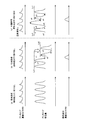
- This transition of the fuel component and the transition of the adsorption amount of ammonia in the SCRF 4 at that time will be described with reference to FIG. FIG.
- the ammonia concentration in the SCRF 4 also periodically increases and decreases corresponding to the urea water supplied periodically, and the ammonia adsorption amount to the SCRF 4 also periodically increases and decreases. is doing. This is because the ammonia that periodically reaches the SCRF 4 is adsorbed by the SCR catalyst supported on the SCRF 4, and the adsorbed ammonia is consumed by reducing the NOx in the exhaust gas.
- the fuel component supplied from the fuel supply valve 6 slips through the oxidation catalyst 3 due to a large exhaust flow rate flowing into the oxidation catalyst 3, as shown in FIG. Reaches SCRF4. At this time, the transition of the amount of adsorbed ammonia on the SCRF 4 when the urea water supply according to the prior art is performed is shown in FIG.
- the adsorption amount increase indicated by the arrow a1 and the arrow c1 are indicated according to the periodic supply of urea water. Adsorption ammonia consumption is repeated. At this time, the ammonia adsorption amount in SCRF4 is at a level indicated by Lv1 in FIG.
- predetermined site a site of the SCR catalyst supported on SCRF 4.
- the urea water supply is controlled so that the amount of ammonia adsorbed on the SCRF 4 in an equilibrium manner does not decrease as much as possible even if the slipping-through fuel component reaches the SCRF 4. Details thereof will be described with reference to FIG. First, until the slipping-through fuel component reaches SCRF4, as in the case shown in FIGS. 2 (a) and 2 (b), the adsorption amount increase indicated by the arrow a3 is increased according to the periodic supply of urea water. The adsorbed ammonia consumption indicated by the arrow c3 is repeated. At this time, the ammonia adsorption amount in SCRF4 is at a level indicated by Lv1 in FIG.
- the ammonia concentration in SCRF 4 at that time becomes higher than the previous ammonia concentration, and the ammonia adsorption amount on SCRF 4 also increases by the amount indicated by arrow a4.
- the amount of increase in the amount of adsorption indicated by the arrow a4 is larger than the amount of increase in the amount of adsorption before that (for example, the amount of increase in the amount of adsorption indicated by the arrow a3). Therefore, as shown in FIG. 2C, the ammonia adsorption amount to SCRF4 temporarily exceeds the level indicated by Lv1, as shown in FIG.
- the SCRF 4 passes through and reaches the fuel component in a state where the ammonia adsorbed for the reduction and purification of NOx in the exhaust is consumed by the amount indicated by the arrow c4.
- the supply amount of urea water when the fuel component does not pass through before the slipping fuel component reaches SCRF4 that is, the increase in the adsorption amount corresponding to the arrow a3.
- the urea water increased in amount compared with the urea water supply amount for realizing the above is supplied. The details of the increased amount of urea water will be described later.
- the so-called increased ammonia produced from the increased amount of supplied urea water is hereinafter referred to as “increased ammonia” (for example, ammonia indicated by arrow a4) and other than that.
- Ammonia generated from the urea water supplied without increasing the amount is referred to as “normal ammonia” (for example, ammonia indicated by arrow a3). Therefore, the increased amount of ammonia is adsorbed to a predetermined site of the SCR catalyst, and the fuel component is adsorbed to the predetermined site through this state.
- SCRF 4 it is adsorbed at a predetermined site of the SCR catalyst.
- the ammonia generated from the urea water is efficient.
- the result is the degree indicated by the arrow a5 in FIG. 2 (c), that is, the influence of the adsorbed fuel component. Only an increase in the amount of adsorption indicated by the arrow a5 occurs, which is smaller than the increase in the amount of adsorption indicated by.
- the amount of ammonia adsorbed on the SCRF 4 is increased before the slipping fuel component reaches the SCRF 4, the amount of adsorbed ammonia is affected by the adsorbed fuel component as described above. Even if it decreases, the ammonia adsorption amount after reaching the slipping fuel component can be maintained at the same level (level indicated by Lv1) as the ammonia adsorption amount before reaching. As a result, even if the adsorption ammonia consumption indicated by the arrow c5 and the adsorption amount increase due to the periodic urea water supply are repeated again, the equilibrium ammonia adsorption amount is maintained at the level indicated by Lv1. Therefore, it is possible to avoid a decrease in the NOx purification rate of SCRF 4 due to the slipping fuel component.
- FIG. 3 shows a time axis on the horizontal axis, (a) urea water supply command issued from the ECU 20 to the supply valve 7, (b) change in ammonia concentration in the SCRF 4, and (c) change in ammonia adsorption amount in the SCRF 4.
- the important point in the NOx purification according to the present invention is that the increased amount of ammonia reaches SCRF4 before the fuel component passes through SCRF4.
- the arrival time of the slip-through fuel component to SCRF4 is represented by t12
- the arrival time of the increased ammonia to SCRF4 is represented by t22.
- the arrival time of normal ammonia that reaches SCRF 4 next to the increased amount of ammonia is represented by t23.
- the supply timing of the urea water from the supply valve 7 (that is, the arrival timing t12 of the slipping fuel component is approximately halfway between the arrival timing t22 of the increased amount of ammonia and the arrival timing t23 of the normal ammonia (that is, A supply command start timing issued from the ECU 20 to the supply valve 7, and a fuel component supply timing from the fuel supply valve 6 (that is, a supply command start timing issued from the ECU 20 to the fuel supply valve 6).
- a time required for a part of the fuel component supplied from the fuel supply valve 6 to pass through and reach the SCRF 4 as a fuel component (hereinafter referred to as “fuel component arrival time”) ⁇ t1
- the time required for the urea water supplied from 7 to reach SCRF4 as ammonia (hereinafter referred to as “ammonia arrival time”) ⁇ t2 is considered.
- the fuel component arrival time ⁇ t1 can be calculated according to Equation 2 below.
- ⁇ t1 (volume from fuel supply valve 6 to SCRF4) / ((Detected value of air flow meter 16 + fuel injection amount per unit time) ⁇ gas density) (2)
- the ammonia arrival time ⁇ t2 can be calculated according to the following equation 3.
- ⁇ t2 (volume from supply valve 6 to SCRF4) / ((Detected value of air flow meter 16 + fuel injection amount per unit time) ⁇ gas density) (3)
- the detected value of the air flow meter 16 + the fuel injection amount per unit time) ⁇ the gas density means the exhaust amount per unit time.
- the fuel component is supplied from the fuel supply valve 6 at time t11 earlier than time t12 by ⁇ t1.
- a supply command may be issued from the ECU 20.
- a supply command may be issued from the ECU 20 so that urea water is supplied from the supply valve 7 at time t21 earlier than time t22 by ⁇ t2.
- the urea water supply command (command having the pulse width W2) corresponding to the increased amount of ammonia is supplied from the urea water supply command (command having the pulse width W1) corresponding to normal ammonia.
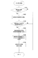
- the NOx purification control shown in FIG. 4 is performed by executing a control program stored in the ECU 20.
- S101 it is determined whether or not it is necessary to supply a fuel component from the fuel supply valve 6.
- the determination process of S101 may be performed in consideration of whether or not it is time to perform the filter regeneration process that is performed when the PM deposition amount in SCRF 4 increases. In this case, if the filter regeneration process is performed, it is determined that the fuel component needs to be supplied.
- the supply conditions necessary for the fuel supply are calculated based on the determination that the fuel supply is necessary. For example, when the fuel component is supplied for the filter regeneration process, the fuel component supply amount is calculated based on the PM amount accumulated in the SCRF 4. Further, the number of injections (injection frequency) by the fuel supply valve 6 is adjusted according to the calculated supply amount of the fuel component so that the fuel component injected from the fuel supply valve 6 is appropriately dispersed in the exhaust gas. .
- the process of S102 ends, the process proceeds to S103.
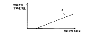
- the amount of fuel components supplied is considered to be a parameter related to the above reaction opportunity. Therefore, for example, as shown in FIG. 5B, whether or not the predetermined condition is satisfied may be determined from the correlation between the supply amount of the fuel component and the slipping amount of the fuel component. As indicated by a line L2 in FIG. 5B, when the supply amount of the fuel component is relatively small, an opportunity for the oxidation reaction of the fuel component in the oxidation catalyst 3 is secured, so that the slip-through amount can be ignored. However, when the supply amount of the fuel component increases beyond the threshold value, it is not sufficiently subjected to the oxidation reaction, and it is considered that the slip-through amount increases according to the increase.
- the above-described exhaust flow rate and fuel component supply amount may be considered in combination, or one of them may be considered.
- the temperature of the oxidation catalyst 3 is also considered as a parameter that may affect the oxidation efficiency of the fuel component, the determination regarding establishment of the predetermined condition may be performed in consideration of the temperature of the oxidation catalyst 3. If a positive determination is made in S103, the process proceeds to S104, and if a negative determination is made, the present control is terminated.
- the urea water supply condition by the supply valve 7 is calculated.
- the amount of urea water for supplying ammonia necessary for NOx reduction and purification is calculated so that the NOx purification rate calculated from the NOx sensors 10 and 11 according to Equation 1 falls within a predetermined purification rate range.
- the increased amount of urea water necessary to generate the increased amount of ammonia described in FIGS. 2 and 3 is also calculated. Specifically, based on the fact that the increased amount of ammonia is for reducing the influence of the fuel component that passes through the oxidation catalyst 3 as described above, it is based on the amount of slip of the fuel component used in the determination process of S103. Thus, the increase amount of the urea water is calculated.
- the amount of increase in urea water is increased as the amount of fuel component slipping through increases.
- the frequency of supplying urea water to the exhaust that is, the interval between one urea water supply and the next urea water supply is also adjusted.
- the fuel component arrival time ⁇ t1 and the ammonia arrival time ⁇ t2 are calculated according to Equations 2 and 3.
- the fuel component supply timing and urea water supply As shown in FIG. 3, that is, the passage of fuel components reaches SCRF 4 at a time during which the next regular ammonia reaches the SCRF 4 (for example, approximately in the middle) between the increased ammonia amounts.
- the timings of the urea water supply command and the fuel component supply command are adjusted.
- the timing of the urea water supply command and the fuel component supply command there is a case where a margin for performing the adjustment is limited depending on the operating state of the internal combustion engine. For example, when the PM collected by SCRF 4 suddenly increases and the filter regeneration process needs to be performed quickly, the fuel component supply command timing is set to the optimum time for the filter regeneration process, and the filter The timing of the urea water supply command may be determined so that the increased ammonia reaches the SCRF 4 before the slipping fuel component generated in the regeneration process.
- the slipping-through fuel component is first applied to SCRF4 from the increased amount of ammonia that will reach SCRF4 by the urea water supply command.
- the timing of the fuel component supply command may be determined so as not to reach it.
- the urea water supply corresponding to the increased amount of ammonia and the passing through of the fuel component reached SCRF 4 once (see FIG. 3), but if the amount of the passing through fuel component reached is large,
- the urea water supply corresponding to the increased amount of ammonia may be continuously performed several times.
- the fuel component is supplied a plurality of times according to the amount of PM to be oxidized and removed in the filter regeneration process, and it is determined that the fuel component slips through corresponding to each supply.
- the urea water supply timing and each fuel component supply timing may be determined based on the technical idea of the present invention shown in the above embodiment so that the increased ammonia and the slipping fuel component alternately reach SCRF4. .
- the SCRF 4 is arranged in the exhaust passage 2.
- a filter for collecting PM and an SCR catalyst for NOx purification are integrally formed.
- a filter and an SCR catalyst may be separately arranged, and PM collection and NOx purification may be performed respectively.
- the filter is disposed in the exhaust passage between the oxidation catalyst 3 and the supply valve 7, and the SCR catalyst is disposed on the downstream side of the supply valve 7.
- by performing the above-described NOx purification control it is possible to reduce the influence of the slip-through fuel component as much as possible and to realize suitable NOx purification.
Landscapes
- Engineering & Computer Science (AREA)
- Chemical & Material Sciences (AREA)
- Combustion & Propulsion (AREA)
- Mechanical Engineering (AREA)
- General Engineering & Computer Science (AREA)
- Chemical Kinetics & Catalysis (AREA)
- Health & Medical Sciences (AREA)
- Toxicology (AREA)
- Biomedical Technology (AREA)
- Environmental & Geological Engineering (AREA)
- Analytical Chemistry (AREA)
- General Chemical & Material Sciences (AREA)
- Oil, Petroleum & Natural Gas (AREA)
- Materials Engineering (AREA)
- Exhaust Gas After Treatment (AREA)
Abstract
Description
NOx浄化率 = 1-(NOxセンサ11の検出値)/(NOxセンサ10の検出値) ・・(式1)
なお、SCRF4が活性された状態にない場合には、供給された尿素水を用いてのNOx浄化を効果的に行えないことから、供給弁7からの尿素水供給は、推定されるSCRF4の温度が、該触媒が活性状態にある所定温度以上となっている場合に行われる。
Δt1=(燃料供給弁6からSCRF4までの容積)/
((エアフローメータ16の検出値+単位時間の燃料噴射量)×ガス密度)・・(式2)
また、アンモニア到達時間Δt2は、以下の式3に従って算出することができる。
Δt2=(供給弁6からSCRF4までの容積)/
((エアフローメータ16の検出値+単位時間の燃料噴射量)×ガス密度)・・(式3)
上記式2および式3において、(エアフローメータ16の検出値+単位時間の燃料噴射量)×ガス密度)は、単位時間当たりの排気量を意味する。
上記実施例では、増量アンモニアに対応する尿素水供給およびすり抜け燃料成分のSCRF4への到達は、それぞれ一回であったが(図3を参照)、すり抜け燃料成分の到達量が多い場合には、増量アンモニアに対応する尿素水供給を数回連続して行ってもよい。また、フィルタ再生処理において酸化除去すべきPM量に応じて燃料成分の供給が複数回にわたって行われる場合であって、且つ各供給に対応して燃料成分のすり抜けが生じると判定される場合には、増量アンモニアとすり抜け燃料成分が交互にSCRF4に到達するように、上記実施例に示した本願発明の技術思想に基づいて各尿素水供給の時期および各燃料成分供給の時期が決定されればよい。
図1に示す内燃機関の排気浄化システムでは、排気通路2にSCRF4が配置され、SCRF4では、PMを捕集するフィルタとNOx浄化のためのSCR触媒がいわば一体的に形成されている。このようなSCRF4の形態に代えて、フィルタとSCR触媒を個別に配置し、それぞれによってPM捕集およびNOx浄化が行われるようにしてもよい。この場合、当該フィルタは、酸化触媒3と供給弁7の間の排気通路に配置され、またSCR触媒は供給弁7の下流側に配置される。このような変形例に係る形態においても、上述したNOx浄化制御が行われることで、すり抜け燃料成分の影響を可及的に軽減させ、好適なNOx浄化を実現することが可能となる。
2 排気通路
3 酸化触媒
4 選択還元型NOx触媒(SCR触媒)
5 ASC触媒
6 燃料供給弁
7 供給弁
9、12 温度センサ
10、11 NOxセンサ
20 ECU
21 クランクポジションセンサ
22 アクセル開度センサ
Claims (6)
- 内燃機関の排気通路に設けられ、酸化機能を有する酸化触媒と、
前記酸化触媒に対して、該酸化触媒に流れ込む排気を介して燃料成分を供給する燃料供給部と、
前記酸化触媒より下流側の排気通路に設けられ、排気中の粒子状物質を捕集するフィルタと、アンモニアを還元剤として排気中のNOxを選択還元する選択還元型NOx触媒とを含んで形成される排気浄化部と、
前記排気浄化部に対して、該排気浄化部に流れ込む排気を介してアンモニア又はアンモニアの前駆体を供給する還元剤供給部と、
前記燃料供給部によって燃料成分が供給される場合に該供給された燃料成分の一部が前記酸化触媒の下流側にすり抜ける所定条件が成立しているとき、該所定条件が成立していない場合において該還元剤供給部によって供給されるべきアンモニア又はアンモニアの前駆体の供給量である非すり抜け時供給量と比べて増量されたアンモニア又はアンモニアの前駆体によるNOx選択還元のためのアンモニアが、該燃料供給部によって供給される燃料成分より先に前記排気浄化部に到達するように、該増量されたアンモニア又はアンモニアの前駆体の供給と該燃料成分の供給の少なくとも一方を制御する供給制御部と、
を備える、内燃機関の排気浄化システム。 - 前記排気浄化部は、前記フィルタに前記選択還元型NOx触媒が担持されて形成されたNOx浄化フィルタである、
請求項1に記載の排気浄化システム。 - 前記供給制御部は、
前記燃料供給部により供給された燃料成分が前記排気浄化部に到達するまでに要する時間と、前記還元剤供給部により供給されたアンモニア又はアンモニアの前駆体によるNOx選択還元のためのアンモニアが該排気浄化部に到達するまでに要する時間に基づいて、該還元剤供給部による供給時期と該燃料供給部による供給時期のうち少なくとも一方を制御する、
請求項1又は請求項2に記載の内燃機関の排気浄化システム。 - 前記内燃機関の運転状態に応じて、前記還元剤供給部によるアンモニア又はアンモニアの前駆体の供給が周期的に行われ、
前記供給制御部は、一の供給時期において前記還元剤供給部から供給された、前記増量されたアンモニア又はアンモニアの前駆体によるNOx選択還元のためのアンモニアが前記排気浄化部に到達する第一到達時期と、該第一到達時期の次に前記還元剤供給部から供給されたアンモニア又はアンモニアの前駆体によるNOx選択還元のためのアンモニアが該排気浄化部に到達する第二到達時期との間の所定時期において、前記燃料供給部により供給された燃料成分が該排気浄化部に到達するように、該還元剤供給部による供給時期と該燃料供給部による供給時期のうち少なくとも一方を制御する、
請求項3に記載の内燃機関の排気浄化システム。 - 前記内燃機関の運転状態に応じて、前記還元剤供給部によるアンモニア又はアンモニアの前駆体の供給が周期的に行われ、
前記燃料供給部による燃料成分の供給が複数回に分けて行われ、
前記供給制御部は、前記還元剤供給部による供給と前記燃料供給部による供給が重複して行われる期間において、前記増量されたアンモニア又はアンモニアの前駆体が該還元剤供給部から供給され、且つ、該還元剤供給部から供給されたアンモニア又はアンモニアの前駆体によるNOx選択還元のためのアンモニアと、該燃料供給部から供給された燃料成分とが、前記排気浄化部に交互に到達するように、該還元剤供給部による供給時期と該燃料供給部による供給時期のうち少なくとも一方を制御する、
請求項3に記載の内燃機関の排気浄化システム。 - 前記所定条件が成立している場合に、前記燃料供給部によって供給された燃料成分が前記酸化触媒の下流側にすり抜けるすり抜け量を、前記内燃機関の運転状態、および前記酸化触媒の温度のうち少なくとも何れかに基づいて算出するすり抜け量算出部を、更に備え、
前記供給制御部は、前記すり抜け量算出部によって算出された燃料成分の前記すり抜け量に基づいて、前記非すり抜け時供給量に対するアンモニア又はアンモニアの前駆体の供給量の増量分を決定する、
請求項1から請求項5の何れか1項に記載の内燃機関の排気浄化システム。
Priority Applications (5)
| Application Number | Priority Date | Filing Date | Title |
|---|---|---|---|
| PCT/JP2013/060512 WO2014162597A1 (ja) | 2013-04-05 | 2013-04-05 | 内燃機関の排気浄化システム |
| EP13880886.0A EP2982838B1 (en) | 2013-04-05 | 2013-04-05 | Exhaust gas purification system of internal combustion engine |
| JP2015509842A JP5994928B2 (ja) | 2013-04-05 | 2013-04-05 | 内燃機関の排気浄化システム |
| US14/781,722 US9810124B2 (en) | 2013-04-05 | 2013-04-05 | Exhaust gas purification system of internal combustion engine |
| CN201380075336.8A CN105074149B (zh) | 2013-04-05 | 2013-04-05 | 内燃机的排气净化系统 |
Applications Claiming Priority (1)
| Application Number | Priority Date | Filing Date | Title |
|---|---|---|---|
| PCT/JP2013/060512 WO2014162597A1 (ja) | 2013-04-05 | 2013-04-05 | 内燃機関の排気浄化システム |
Publications (1)
| Publication Number | Publication Date |
|---|---|
| WO2014162597A1 true WO2014162597A1 (ja) | 2014-10-09 |
Family
ID=51657923
Family Applications (1)
| Application Number | Title | Priority Date | Filing Date |
|---|---|---|---|
| PCT/JP2013/060512 Ceased WO2014162597A1 (ja) | 2013-04-05 | 2013-04-05 | 内燃機関の排気浄化システム |
Country Status (5)
| Country | Link |
|---|---|
| US (1) | US9810124B2 (ja) |
| EP (1) | EP2982838B1 (ja) |
| JP (1) | JP5994928B2 (ja) |
| CN (1) | CN105074149B (ja) |
| WO (1) | WO2014162597A1 (ja) |
Cited By (4)
| Publication number | Priority date | Publication date | Assignee | Title |
|---|---|---|---|---|
| JP2016089699A (ja) * | 2014-11-04 | 2016-05-23 | 本田技研工業株式会社 | 内燃機関の排気浄化装置 |
| JP2016102424A (ja) * | 2014-11-27 | 2016-06-02 | トヨタ自動車株式会社 | 内燃機関の排気浄化システム |
| JP2016183563A (ja) * | 2015-03-25 | 2016-10-20 | トヨタ自動車株式会社 | 排気浄化装置 |
| US10799833B2 (en) | 2015-08-03 | 2020-10-13 | Cummins Emission Solutions Inc. | Sensor configuration for aftertreatment system including SCR on filter |
Families Citing this family (1)
| Publication number | Priority date | Publication date | Assignee | Title |
|---|---|---|---|---|
| US11073067B2 (en) | 2019-01-10 | 2021-07-27 | Deere & Company | Exhaust gas treatment system and method with reductant injection and close-coupled treatment element |
Citations (8)
| Publication number | Priority date | Publication date | Assignee | Title |
|---|---|---|---|---|
| JP2007501353A (ja) | 2003-08-05 | 2007-01-25 | エンゲルハード・コーポレーシヨン | Scr濾過器を用いた排気処理システムおよび方法 |
| JP2007239500A (ja) * | 2006-03-06 | 2007-09-20 | Toyota Motor Corp | 内燃機関の排気浄化装置 |
| JP2008215123A (ja) * | 2007-03-01 | 2008-09-18 | Toyota Motor Corp | 内燃機関の排気浄化装置 |
| JP2008231966A (ja) * | 2007-03-19 | 2008-10-02 | Toyota Motor Corp | 圧縮着火式内燃機関の排気浄化装置 |
| JP2009041437A (ja) | 2007-08-08 | 2009-02-26 | Toyota Motor Corp | 圧縮着火式内燃機関の排気浄化装置 |
| WO2009110102A1 (ja) * | 2008-03-04 | 2009-09-11 | トヨタ自動車株式会社 | 内燃機関の排気浄化装置 |
| JP2010540818A (ja) * | 2007-09-28 | 2010-12-24 | ダイムラー・アクチェンゲゼルシャフト | 希薄燃焼内燃機関を搭載する車両での窒素酸化物排出削減方法 |
| JP2011001875A (ja) * | 2009-06-18 | 2011-01-06 | Isuzu Motors Ltd | 排気浄化装置 |
Family Cites Families (3)
| Publication number | Priority date | Publication date | Assignee | Title |
|---|---|---|---|---|
| US6928806B2 (en) * | 2002-11-21 | 2005-08-16 | Ford Global Technologies, Llc | Exhaust gas aftertreatment systems |
| US8904760B2 (en) * | 2009-06-17 | 2014-12-09 | GM Global Technology Operations LLC | Exhaust gas treatment system including an HC-SCR and two-way catalyst and method of using the same |
| JP2013002314A (ja) * | 2011-06-14 | 2013-01-07 | Hino Motors Ltd | 排気浄化装置 |
-
2013
- 2013-04-05 WO PCT/JP2013/060512 patent/WO2014162597A1/ja not_active Ceased
- 2013-04-05 US US14/781,722 patent/US9810124B2/en not_active Expired - Fee Related
- 2013-04-05 JP JP2015509842A patent/JP5994928B2/ja active Active
- 2013-04-05 EP EP13880886.0A patent/EP2982838B1/en not_active Not-in-force
- 2013-04-05 CN CN201380075336.8A patent/CN105074149B/zh not_active Expired - Fee Related
Patent Citations (8)
| Publication number | Priority date | Publication date | Assignee | Title |
|---|---|---|---|---|
| JP2007501353A (ja) | 2003-08-05 | 2007-01-25 | エンゲルハード・コーポレーシヨン | Scr濾過器を用いた排気処理システムおよび方法 |
| JP2007239500A (ja) * | 2006-03-06 | 2007-09-20 | Toyota Motor Corp | 内燃機関の排気浄化装置 |
| JP2008215123A (ja) * | 2007-03-01 | 2008-09-18 | Toyota Motor Corp | 内燃機関の排気浄化装置 |
| JP2008231966A (ja) * | 2007-03-19 | 2008-10-02 | Toyota Motor Corp | 圧縮着火式内燃機関の排気浄化装置 |
| JP2009041437A (ja) | 2007-08-08 | 2009-02-26 | Toyota Motor Corp | 圧縮着火式内燃機関の排気浄化装置 |
| JP2010540818A (ja) * | 2007-09-28 | 2010-12-24 | ダイムラー・アクチェンゲゼルシャフト | 希薄燃焼内燃機関を搭載する車両での窒素酸化物排出削減方法 |
| WO2009110102A1 (ja) * | 2008-03-04 | 2009-09-11 | トヨタ自動車株式会社 | 内燃機関の排気浄化装置 |
| JP2011001875A (ja) * | 2009-06-18 | 2011-01-06 | Isuzu Motors Ltd | 排気浄化装置 |
Cited By (5)
| Publication number | Priority date | Publication date | Assignee | Title |
|---|---|---|---|---|
| JP2016089699A (ja) * | 2014-11-04 | 2016-05-23 | 本田技研工業株式会社 | 内燃機関の排気浄化装置 |
| JP2016102424A (ja) * | 2014-11-27 | 2016-06-02 | トヨタ自動車株式会社 | 内燃機関の排気浄化システム |
| JP2016183563A (ja) * | 2015-03-25 | 2016-10-20 | トヨタ自動車株式会社 | 排気浄化装置 |
| US10799833B2 (en) | 2015-08-03 | 2020-10-13 | Cummins Emission Solutions Inc. | Sensor configuration for aftertreatment system including SCR on filter |
| GB2556753B (en) * | 2015-08-03 | 2020-12-09 | Cummins Emission Solutions Inc | Sensor configuration for aftertreatment system including SCR on filter |
Also Published As
| Publication number | Publication date |
|---|---|
| CN105074149B (zh) | 2017-09-22 |
| EP2982838A1 (en) | 2016-02-10 |
| CN105074149A (zh) | 2015-11-18 |
| US9810124B2 (en) | 2017-11-07 |
| EP2982838B1 (en) | 2018-08-15 |
| US20170089242A1 (en) | 2017-03-30 |
| EP2982838A4 (en) | 2016-04-06 |
| JPWO2014162597A1 (ja) | 2017-02-16 |
| JP5994928B2 (ja) | 2016-09-21 |
Similar Documents
| Publication | Publication Date | Title |
|---|---|---|
| JP6187385B2 (ja) | 内燃機関の排気浄化装置 | |
| JP5002040B2 (ja) | 内燃機関の排気浄化装置 | |
| JP2007162578A (ja) | 排気ガス浄化システムの制御方法及び排気ガス浄化システム | |
| CN103635664B (zh) | 内燃机的排气净化装置 | |
| JP5915623B2 (ja) | 内燃機関の排気浄化システム | |
| JP5994928B2 (ja) | 内燃機関の排気浄化システム | |
| JP5251711B2 (ja) | 内燃機関の排気浄化装置 | |
| JP5333664B2 (ja) | 内燃機関の排気浄化装置 | |
| US20150292378A1 (en) | Exhaust gas purification system for internal combustion engine | |
| JP5338973B2 (ja) | 内燃機関の排気浄化装置 | |
| EP2940265A1 (en) | Exhaust purification system for internal combustion engine | |
| JP5983438B2 (ja) | 内燃機関の排気浄化装置 | |
| JP2009293466A (ja) | エンジンの空燃比センサ再生制御装置 | |
| US9464554B2 (en) | Exhaust gas purification system for internal combustion engine | |
| JP2010005552A (ja) | 内燃機関の排気浄化装置 | |
| JP2010249076A (ja) | 内燃機関の排気浄化装置 | |
| JP6252375B2 (ja) | 内燃機関の排気ガス浄化システム及び内燃機関の排気ガス浄化方法 | |
| CN111788372A (zh) | 内燃机的排气气体净化系统及内燃机的排气气体净化方法 | |
| JP2017025710A (ja) | 内燃機関の排気浄化システム | |
| JP2008115712A (ja) | 内燃機関の排気浄化装置 |
Legal Events
| Date | Code | Title | Description |
|---|---|---|---|
| WWE | Wipo information: entry into national phase |
Ref document number: 201380075336.8 Country of ref document: CN |
|
| 121 | Ep: the epo has been informed by wipo that ep was designated in this application |
Ref document number: 13880886 Country of ref document: EP Kind code of ref document: A1 |
|
| WWE | Wipo information: entry into national phase |
Ref document number: 14781722 Country of ref document: US |
|
| ENP | Entry into the national phase |
Ref document number: 2015509842 Country of ref document: JP Kind code of ref document: A |
|
| NENP | Non-entry into the national phase |
Ref country code: DE |
|
| WWE | Wipo information: entry into national phase |
Ref document number: 2013880886 Country of ref document: EP |