WO2014162763A1 - 塩水淡水化装置 - Google Patents
塩水淡水化装置 Download PDFInfo
- Publication number
- WO2014162763A1 WO2014162763A1 PCT/JP2014/051873 JP2014051873W WO2014162763A1 WO 2014162763 A1 WO2014162763 A1 WO 2014162763A1 JP 2014051873 W JP2014051873 W JP 2014051873W WO 2014162763 A1 WO2014162763 A1 WO 2014162763A1
- Authority
- WO
- WIPO (PCT)
- Prior art keywords
- salt water
- osmosis membrane
- water
- pressure
- membrane member
- Prior art date
- Legal status (The legal status is an assumption and is not a legal conclusion. Google has not performed a legal analysis and makes no representation as to the accuracy of the status listed.)
- Ceased
Links
Images





Classifications
-
- B—PERFORMING OPERATIONS; TRANSPORTING
- B01—PHYSICAL OR CHEMICAL PROCESSES OR APPARATUS IN GENERAL
- B01D—SEPARATION
- B01D61/00—Processes of separation using semi-permeable membranes, e.g. dialysis, osmosis or ultrafiltration; Apparatus, accessories or auxiliary operations specially adapted therefor
- B01D61/02—Reverse osmosis; Hyperfiltration ; Nanofiltration
- B01D61/10—Accessories; Auxiliary operations
-
- B—PERFORMING OPERATIONS; TRANSPORTING
- B01—PHYSICAL OR CHEMICAL PROCESSES OR APPARATUS IN GENERAL
- B01D—SEPARATION
- B01D61/00—Processes of separation using semi-permeable membranes, e.g. dialysis, osmosis or ultrafiltration; Apparatus, accessories or auxiliary operations specially adapted therefor
- B01D61/002—Forward osmosis or direct osmosis
- B01D61/0022—Apparatus therefor
-
- B—PERFORMING OPERATIONS; TRANSPORTING
- B01—PHYSICAL OR CHEMICAL PROCESSES OR APPARATUS IN GENERAL
- B01D—SEPARATION
- B01D61/00—Processes of separation using semi-permeable membranes, e.g. dialysis, osmosis or ultrafiltration; Apparatus, accessories or auxiliary operations specially adapted therefor
- B01D61/58—Multistep processes
-
- C—CHEMISTRY; METALLURGY
- C02—TREATMENT OF WATER, WASTE WATER, SEWAGE, OR SLUDGE
- C02F—TREATMENT OF WATER, WASTE WATER, SEWAGE, OR SLUDGE
- C02F1/00—Treatment of water, waste water, or sewage
- C02F1/44—Treatment of water, waste water, or sewage by dialysis, osmosis or reverse osmosis
- C02F1/441—Treatment of water, waste water, or sewage by dialysis, osmosis or reverse osmosis by reverse osmosis
-
- C—CHEMISTRY; METALLURGY
- C02—TREATMENT OF WATER, WASTE WATER, SEWAGE, OR SLUDGE
- C02F—TREATMENT OF WATER, WASTE WATER, SEWAGE, OR SLUDGE
- C02F1/00—Treatment of water, waste water, or sewage
- C02F1/44—Treatment of water, waste water, or sewage by dialysis, osmosis or reverse osmosis
- C02F1/445—Treatment of water, waste water, or sewage by dialysis, osmosis or reverse osmosis by forward osmosis
-
- B—PERFORMING OPERATIONS; TRANSPORTING
- B01—PHYSICAL OR CHEMICAL PROCESSES OR APPARATUS IN GENERAL
- B01D—SEPARATION
- B01D2311/00—Details relating to membrane separation process operations and control
- B01D2311/04—Specific process operations in the feed stream; Feed pretreatment
-
- B—PERFORMING OPERATIONS; TRANSPORTING
- B01—PHYSICAL OR CHEMICAL PROCESSES OR APPARATUS IN GENERAL
- B01D—SEPARATION
- B01D2311/00—Details relating to membrane separation process operations and control
- B01D2311/08—Specific process operations in the concentrate stream
-
- B—PERFORMING OPERATIONS; TRANSPORTING
- B01—PHYSICAL OR CHEMICAL PROCESSES OR APPARATUS IN GENERAL
- B01D—SEPARATION
- B01D2313/00—Details relating to membrane modules or apparatus
- B01D2313/24—Specific pressurizing or depressurizing means
- B01D2313/243—Pumps
-
- B—PERFORMING OPERATIONS; TRANSPORTING
- B01—PHYSICAL OR CHEMICAL PROCESSES OR APPARATUS IN GENERAL
- B01D—SEPARATION
- B01D2313/00—Details relating to membrane modules or apparatus
- B01D2313/24—Specific pressurizing or depressurizing means
- B01D2313/246—Energy recovery means
-
- B—PERFORMING OPERATIONS; TRANSPORTING
- B01—PHYSICAL OR CHEMICAL PROCESSES OR APPARATUS IN GENERAL
- B01D—SEPARATION
- B01D2317/00—Membrane module arrangements within a plant or an apparatus
- B01D2317/02—Elements in series
- B01D2317/022—Reject series
-
- B—PERFORMING OPERATIONS; TRANSPORTING
- B01—PHYSICAL OR CHEMICAL PROCESSES OR APPARATUS IN GENERAL
- B01D—SEPARATION
- B01D61/00—Processes of separation using semi-permeable membranes, e.g. dialysis, osmosis or ultrafiltration; Apparatus, accessories or auxiliary operations specially adapted therefor
- B01D61/02—Reverse osmosis; Hyperfiltration ; Nanofiltration
- B01D61/025—Reverse osmosis; Hyperfiltration
-
- B—PERFORMING OPERATIONS; TRANSPORTING
- B01—PHYSICAL OR CHEMICAL PROCESSES OR APPARATUS IN GENERAL
- B01D—SEPARATION
- B01D61/00—Processes of separation using semi-permeable membranes, e.g. dialysis, osmosis or ultrafiltration; Apparatus, accessories or auxiliary operations specially adapted therefor
- B01D61/02—Reverse osmosis; Hyperfiltration ; Nanofiltration
- B01D61/12—Controlling or regulating
-
- C—CHEMISTRY; METALLURGY
- C02—TREATMENT OF WATER, WASTE WATER, SEWAGE, OR SLUDGE
- C02F—TREATMENT OF WATER, WASTE WATER, SEWAGE, OR SLUDGE
- C02F2103/00—Nature of the water, waste water, sewage or sludge to be treated
- C02F2103/08—Seawater, e.g. for desalination
-
- C—CHEMISTRY; METALLURGY
- C02—TREATMENT OF WATER, WASTE WATER, SEWAGE, OR SLUDGE
- C02F—TREATMENT OF WATER, WASTE WATER, SEWAGE, OR SLUDGE
- C02F2303/00—Specific treatment goals
- C02F2303/10—Energy recovery
-
- Y—GENERAL TAGGING OF NEW TECHNOLOGICAL DEVELOPMENTS; GENERAL TAGGING OF CROSS-SECTIONAL TECHNOLOGIES SPANNING OVER SEVERAL SECTIONS OF THE IPC; TECHNICAL SUBJECTS COVERED BY FORMER USPC CROSS-REFERENCE ART COLLECTIONS [XRACs] AND DIGESTS
- Y02—TECHNOLOGIES OR APPLICATIONS FOR MITIGATION OR ADAPTATION AGAINST CLIMATE CHANGE
- Y02A—TECHNOLOGIES FOR ADAPTATION TO CLIMATE CHANGE
- Y02A20/00—Water conservation; Efficient water supply; Efficient water use
- Y02A20/124—Water desalination
- Y02A20/131—Reverse-osmosis
-
- Y—GENERAL TAGGING OF NEW TECHNOLOGICAL DEVELOPMENTS; GENERAL TAGGING OF CROSS-SECTIONAL TECHNOLOGIES SPANNING OVER SEVERAL SECTIONS OF THE IPC; TECHNICAL SUBJECTS COVERED BY FORMER USPC CROSS-REFERENCE ART COLLECTIONS [XRACs] AND DIGESTS
- Y02—TECHNOLOGIES OR APPLICATIONS FOR MITIGATION OR ADAPTATION AGAINST CLIMATE CHANGE
- Y02W—CLIMATE CHANGE MITIGATION TECHNOLOGIES RELATED TO WASTEWATER TREATMENT OR WASTE MANAGEMENT
- Y02W10/00—Technologies for wastewater treatment
- Y02W10/30—Wastewater or sewage treatment systems using renewable energies
Definitions
- the present invention is a salt water desalination apparatus that desalinates salt water using an osmosis membrane, and is obtained in desalination in order to reduce power consumption of a salt water supply pump that supplies salt water to the osmosis membrane that performs desalination.
- the present invention relates to a salt water desalination apparatus that utilizes concentrated salt water having a high pressure.
- a saltwater desalination apparatus for desalinating saltwater has been installed in coastal areas and the like to obtain freshwater from saltwater.
- salt water desalination equipment is installed in relatively quiet inland seas such as coasts and bays in urban areas where water shortages are likely to occur.
- the salt water desalination apparatus takes in salt water in the inland sea and generates fresh water using a member such as a reverse osmosis membrane or a forward osmosis membrane. The generated fresh water is used as domestic water.
- Patent Document 1 discloses a first chamber of a forward osmosis membrane treatment means that is supplied with raw water (brine) in contact with a forward osmosis membrane, and a high osmosis for collecting water by permeating the membrane from salt water in contact with the forward osmosis membrane.
- Patent Document 1 discloses a technique for removing substances adhering to the forward osmosis membrane with the brine supplied to the forward osmosis membrane for desalinating the brine. By removing the adhering substances, the desalination ability of the forward osmosis membrane can be maintained, and the time durability of the saltwater freshwater system can be improved.
- Patent Document 1 Although the saltwater freshwater system disclosed in Patent Document 1 can maintain the capability of the forward osmosis membrane, it does not lead to a reduction in the load of the saltwater supply pump. For this reason, it does not lead to a reduction in power consumption of the saltwater freshwater system, and the cost of the saltwater freshwater is large, which becomes an obstacle to the spread.
- Patent Document 2 describes an adjustment for adjusting the flow rate of concentrated water discharged from a high-pressure RO membrane filter 4 that separates salt water into permeate and concentrated water, a high-pressure pump P1, a power recovery device 5, and a power recovery device.
- a valve V5 a first flow meter Q1 that measures the flow rate of the concentrated water, a low pressure RO membrane filter 7 that separates the high pressure reverse osmosis membrane permeate water into permeate and concentrated water, a low pressure pump P2, and a low pressure Adjusting valve V6 for adjusting the flow rate of concentrated water discharged from the RO membrane filter, second flow meter Q2 for measuring the flow rate of the concentrated water, and measuring the temperature of salt water supplied to the high-pressure RO membrane filter
- a control unit 11 and 12 for adjusting the valve opening
- the purpose is to maintain a constant saltwater freshwater capacity that varies with saltwater temperature by adjusting the flow rate.
- Patent Document 2 does not lead to a load reduction of the salt water supply pump. For this reason, it does not lead to a reduction in power consumption of the saltwater freshwater system, and the cost of the saltwater freshwater is large, which becomes an obstacle to the spread.
- Patent Document 3 discloses a concentrated water discharged from a reverse osmosis membrane separation device 4 in a salt water fresh water system in which salt water pressurized by a pump is passed through a reverse osmosis membrane separation device 4 and separated into fresh water and concentrated salt water to produce fresh water from the salt water.
- An energy exchange chamber 20 that uses the pressure energy of salt water as energy for boosting a part of the salt water is provided.
- the energy exchange chamber 20 includes a concentrated salt water port P1 for entering and leaving the concentrated salt water, and a salt water port P2 for entering and exiting the salt water.
- a plurality of partitioned flow paths R that are provided in the chamber and communicate with the concentrated salt water port P1 and the salt water port P2.
- the plurality of partitioned flow paths R have the same cross-sectional area and the same shape.
- the other part discloses a saltwater freshwater system in which fluid does not flow.
- Patent Document 3 increases the input capability of salt water from the salt water port P2 by the energy exchange chamber 20 that increases the pressure of the salt water using the pressure energy of the concentrated salt water with respect to the salt water port P2 corresponding to the salt water supply pump.
- the purpose is that.
- the saltwater freshwater system disclosed in Patent Document 3 aims to reduce the load of the saltwater supply pump.
- Patent Documents 1 to 3 assume only desalination using a reverse osmosis membrane and only concentrated salt water at a high pressure generated from the reverse osmosis membrane. However, there is a problem that only a concentrated salt water generated in a reverse osmosis membrane has a small width that can be utilized.
- the conventional salt water desalination apparatus has a problem that the load related to the salt water supply pump that supplies the salt water and the power consumption therefor cannot be efficiently reduced. As a result, the running cost of the saltwater desalination apparatus is increased, which hinders the spread. In particular, there are many developing countries in countries and regions that require saltwater desalination devices due to water shortages, and high running costs have become bottlenecks for introduction.
- An object of the present invention is to provide a salt water desalination apparatus capable of solving such problems and reducing the load and power consumption of the salt water supply pump.
- the salt water desalination apparatus of the present invention includes a salt water supply means for supplying salt water to a reverse osmosis membrane member, a forward osmosis membrane member to which concentrated salt water discharged from the reverse osmosis membrane member is supplied, and forward osmosis.
- An auxiliary device that is supplied with the mixed water discharged from the membrane member and is connected to the salt water supply means. The auxiliary device supplies power to the salt water supply means, pressure applied to the salt water supply means, and salt water supply means. Increase at least one of the ability to rotate.
- the salt water desalination apparatus of the present invention supplies the high-pressure concentrated salt water obtained from the reverse osmosis membrane member directly or indirectly to the forward osmosis membrane member, and the high-pressure concentrated salt water obtained from the forward osmosis membrane member It can be used as a power source for the auxiliary device of the supply pump.
- the load of the salt water supply pump can be reduced in various manners, and the capacity of the salt water supply pump can be improved. As a result, it is possible to reduce the load of the salt water supply pump and reduce power consumption.
- Reducing the power consumption of the salt water supply pump reduces the running cost of the salt water desalination device and promotes the spread of the salt water desalination device. As a result, it is possible to secure domestic water using salt water in countries and regions suffering from water shortages. Furthermore, by securing water for daily use, regional conflicts are less likely to occur, contributing to regional stability.
- FIG. 6 is a schematic diagram showing another example of a forward osmosis membrane member in Embodiment 1.
- FIG. It is a block diagram of the salt water desalination apparatus in the variation 1 in Embodiment 2 of this invention.
- the salt water desalination apparatus includes a salt water supply means for supplying salt water to the reverse osmosis membrane member, a forward osmosis membrane member to which concentrated salt water discharged from the reverse osmosis membrane member is supplied, An auxiliary device that is supplied with the mixed water discharged from the osmotic membrane member and is connected to the salt water supply means, and the auxiliary device supplies power to the salt water supply means, application pressure to the salt water supply means, and salt water supply Increase at least one of the ability to rotate to the means.
- the concentrated salt water generated in the reverse osmosis membrane is not released to the outside as it is, and the environmental load can be directly reduced.
- the concentrated salt water as mixed water in which the amount of water is increased by the forward osmosis membrane member, it is possible to use the increased amount of water to reduce power consumption and energy consumption required for the salt water supply means. That is, energy saving can be realized and the environmental load can be indirectly reduced.
- the saltwater supply means is a saltwater supply pump.
- This configuration can reduce the cost of the salt water supply means.
- the reverse osmosis membrane member in addition to the first or second invention, includes a salt water passage through which the salt water supplied from the salt water supply means is introduced, and a membrane And a fresh water passage through which fresh water from which salt water has been removed by reverse osmosis is passed, the concentrated salt water is discharged from the salt water passage, and fresh water is supplied from the fresh water passage.
- This configuration allows the reverse osmosis membrane member to produce fresh water while producing concentrated salt water.
- the salt water desalination apparatus can implement
- the forward osmosis membrane member is supplied with the concentrated salt water and the treated fresh water. And a treated fresh water passage through which the water molecules move from the treated fresh water passage to the concentrated salt water passage due to the forward osmosis phenomenon, and the forward osmosis membrane member generates mixed water to the auxiliary device. Output.
- This configuration allows the forward osmosis membrane member to generate mixed water with an increased amount of energy by increasing the amount of water while maintaining the pressure of concentrated salt water.
- This mixed water can operate the auxiliary device to reduce the power consumption and energy consumption of the entire salt water desalination apparatus.
- the mixed water has a lower salt concentration than the concentrated salt water.
- This configuration can reduce the environmental burden due to the wastewater that is finally released to the outside world.
- the mixed water has at least one of a higher water amount and higher energy than the concentrated salt water.
- This configuration allows the mixed water to operate with higher efficiency than to operate the auxiliary device with concentrated salt water.
- the salt water desalination apparatus can perform an energy saving operation as a whole.
- the salt water supply means is a salt water supply pump for supplying salt water by rotating along the rotation axis.
- the auxiliary device includes a rotation auxiliary member that is connected to the rotation shaft and increases at least one of the rotation speed and the rotation force of the salt water supply pump.
- This configuration can reduce the power consumption and energy consumption of the salt water supply means with an easy configuration.
- the rotation auxiliary member in addition to the seventh aspect, the rotation auxiliary member generates a rotational force by the pressure of the supplied mixed water, and passes through the rotating shaft to be connected to the salt water. Increasing at least one of the rotational speed and rotational force of the supply pump.
- the auxiliary device in addition to any one of the first to sixth aspects of the invention, when the salt water supply means is a salt water supply pump operated by electric power, the auxiliary device is It has an electric power generation part which generates auxiliary power supplied to a salt water supply pump, and salt water supply pump operates also using auxiliary power.
- This configuration can reduce the power consumption of the salt water supply means.
- the mixed water rotates the turbine of the power generation unit by its pressure.
- This configuration allows mixed water to generate auxiliary power.
- the auxiliary device has a second pressure conversion means connected to the salt water supply means,
- the pressure conversion means receives the mixed water and increases the pressure of the salt water input to the salt water supply means, and the second pressure conversion means supplies the salt water whose pressure has been increased to the reverse osmosis membrane member.
- This configuration can reduce the load on the salt water supply means.
- the salt pressure desalination apparatus further includes a third pressure conversion means in the front stage of the forward osmosis membrane member, The means increases the pressure of the supplied concentrated brine using the mixed water released from the forward osmosis membrane member.
- the mixed water can be distributed in a balanced manner, and the energy consumption of the mixed water can be increased while reducing the energy consumption of the salt water supply means. As a result, power consumption and energy consumption in the entire salt water desalination apparatus can be reduced.
- the salt water supply means for supplying the salt water from the salt water source to the reverse osmosis membrane member is divided into a plurality of paths, The reverse osmosis membrane member is supplied, and a part of the plurality of paths has first pressure conversion means, the reverse osmosis membrane member supplies concentrated salt water to the first pressure means, and the first pressure conversion means Based on the pressure of the concentrated salt water, the pressure of the salt water supplied to the reverse osmosis membrane member is increased, and the first pressure converting means supplies the concentrated salt water used for the pressure increase to the forward osmosis membrane member.
- This configuration can appropriately adjust the amount of salt water supplied to the reverse osmosis membrane member.
- the concentrated salt water supplied from the reverse osmosis membrane member can be appropriately used to reduce power consumption and energy consumption in the entire salt water desalination apparatus.
- FIG. 1 is a block diagram of a general salt water desalination apparatus using a reverse osmosis membrane.
- the salt water desalination apparatus 100 includes a salt water supply means 110 and a reverse osmosis membrane member 120.
- the salt water supply means 110 supplies the salt water 101 to the reverse osmosis membrane member 120.
- the reverse osmosis membrane member is separated into a salt water passage and a fresh water passage. Under the pressure of the supplied salt water, the reverse osmosis membrane member exudes water molecules from the salt water in the salt water passage through the reverse osmosis membrane into the fresh water passage. As a result, the reverse osmosis membrane member 120 releases the fresh water 102 and the concentrated salt water 103 whose salinity is increased.
- Fresh water 102 is used as domestic water, industrial water, etc. as fresh water.
- the concentrated salt water 103 is generally discarded in the salt water desalination apparatus 100.
- the concentrated salt water 103 is discharged into the sea where the salt water desalination apparatus 100 is often installed or sewage connected to the sea.
- the normal salt water desalination apparatus 100 generates fresh water by using the reverse osmosis membrane member 120 for salt water (including salt water from a salt water lake, of course) including seawater.
- the concentrated salt water generated in the process of producing fresh water is discharged as it is and discarded.
- FIG. 2 is a block diagram of a power recovery type salt water desalination apparatus according to the reference technique.
- the salt water desalination apparatus 200 basically supplies the salt water 101 to the reverse osmosis membrane member 120 by the salt water supply means 110 (P-1).
- the reverse osmosis membrane member 120 causes water molecules to ooze out from the supplied salt water through the osmosis membrane in the same manner as the salt water desalination apparatus 100 of FIG.
- the reverse osmosis membrane member 120 releases the concentrated salt water 103 having a pressure, like the salt water desalination apparatus 100.
- the power recovery type salt water desalination apparatus 200 shown in FIG. 2 uses the pressure of the concentrated salt water 103.
- the concentrated salt water 103 is supplied to the pressure conversion means 130.
- the pressure converting means 130 increases the pressure when the salt water supplied from the salt water supplying means 111 (shown as P-2 in the figure) is supplied to the reverse osmosis membrane member 120. That is, the concentrated salt water 103 increases the supply pressure of salt water from the salt water supply means 111 via the pressure conversion means 130.
- the salt water supply means 112 is connected to the subsequent stage of the pressure conversion means 130, and the salt water supply means 112 finally supplies the salt water to the reverse osmosis membrane member 120.
- this salt water supply means 112 salt water whose pressure has been increased by the pressure conversion means 130 that has received the pressure of the concentrated salt water 103 enters, so that the salt water supply means 112 reversely osmosis the salt water 101 at a pressure exceeding its original capacity.
- the film member 120 can be supplied.
- the power recovery-type salt water desalination apparatus 200 shown in FIG. 2 includes salt water supply means 110 that supplies the salt water 101 directly to the reverse osmosis membrane member 120, and salt water supply means that passes through the pressure conversion means 130. 112 in parallel with the salt water.
- salt water supply means 110 By supplying salt water in parallel, the burden on the salt water supply means 110 for pumping salt water from the sea or lake is reduced.
- the salt water supply means 110 has to increase the pressure from a state where there is almost no water pressure to a constant water pressure when taking salt water from the sea or the lake. Is big.
- the saltwater desalination apparatus 200 of FIG. 2 can reduce the power consumption and energy consumption required for the saltwater supply to the reverse osmosis membrane member 120.
- the concentrated salt water 104 after being used for the pressure increase in the pressure conversion means 130 is discharged as it is.
- the concentrated salt water 103 released from the reverse osmosis membrane member 120 used in the pressure converting means 130 is used for increasing the pressure in the pressure converting means 130, the pressure is almost lost thereafter. That is, the concentrated salt water 104 after being used in the pressure converting means 130 has almost no pressure, and has lost its utility value as an energy source. For this reason, this concentrated salt water 104 is discharged as described above.
- water may be discharged from the salt water desalination apparatus 200 into the sea or discharged into sewage.
- the concentrated salt water 104 has a very high salinity, and if this concentrated salt water 104 is discharged into the sea, there is a concern that it may have an adverse effect on the environment.
- it is required to mix fresh water with the concentrated brine 104 (for example, river water or lake water) and discharge it into the sea. It is done.
- the saltwater desalination apparatuses 100 and 200 of the reference technology shown in FIGS. 1 and 2 still have problems in terms of power recovery and environmental load.
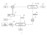
- FIG. 3 is a block diagram of the salt water desalination apparatus according to Embodiment 1 of the present invention.
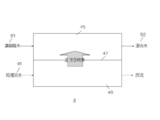
- FIG. 4 is a schematic diagram of a forward osmosis membrane member according to Embodiment 1 of the present invention.
- the saltwater desalination apparatus 1 includes a saltwater supply means 2, a reverse osmosis membrane member 3, a forward osmosis membrane member 4, and an auxiliary device 5 as main elements. Of course, other elements may be provided as necessary.
- the salt water supply means 2 supplies the salt water 30 to the reverse osmosis membrane member 3.
- the salt water 30 includes sea water, lake water of a salt lake, various waters including salt or the like that are stored or distributed naturally or artificially.
- the salt water supply means 2 should just be comprised by various equipment and apparatuses, it is suitable that it is a salt water supply pump.
- elements having a description such as “P-1” are elements having a function of feeding salt water, fresh water, etc. from the preceding stage to the subsequent elements by suction, represented by a pump. Show. Numeric parts such as “P-1” and “P-2” are described for distinguishing elements typified by such pumps.
- the reverse osmosis membrane member 3 is supplied with salt water from the salt water supply means 2.
- the reverse osmosis membrane member 33 has a reverse osmosis membrane, and a salt water passage 31 (not clearly shown in FIG. 3) through which the salt water supplied from the salt water supply means 2 is introduced by the reverse osmosis membrane. And a fresh water passage 32 (not clearly shown in FIG. 3) through which fresh water from which the salt water passing through the salt water passage 31 has been removed by the reverse osmosis phenomenon in the reverse osmosis membrane.
- the reverse osmosis membrane uses osmotic pressure to pass water molecules from the salt water passing through the salt water passage 31 toward the fresh water passage 32 (reverse osmosis membrane phenomenon). By passing the water molecules, fresh water produced from salt water is generated on the fresh water passage 32 side. The generated fresh water is discharged as fresh water 40 through the fresh water passage 32. That is, the reverse osmosis membrane member 3 generates and discharges fresh water 40 from salt water. The released fresh water 40 is used as domestic water or industrial water.
- Salt water desalination which is a basic function of the salt water desalination apparatus 1, is realized by the salt water supply means 2 and the reverse osmosis membrane member 3.
- the salt water passing through the salt water passage 31 releases concentrated salt water 51 having a higher salinity than the salt water 30 supplied by the reverse osmosis membrane phenomenon while passing through the salt water passage 31.
- the concentrated salt water 51 not only has a higher salt concentration, but also has a higher pressure than the supplied salt water 30.
- the reverse osmosis membrane member 3 supplies this concentrated salt water 51 with increased salinity and pressure to the forward osmosis membrane member 4 through other elements as necessary.
- the reverse osmosis membrane member 3 supplies the concentrated salt water 51 to be released to the forward osmosis membrane member 4 via the pump 21.
- the pump 21 plays a role of supplying the concentrated salt water 51 discharged from the reverse osmosis membrane member 3 to the forward osmosis membrane member 4, but at this time, the pressure of the concentrated salt water 51 may be lowered and supplied.
- the pump 21 may have a role of appropriately supplying the concentrated salt water 51 discharged from the reverse osmosis membrane member 3 to the forward osmosis membrane member 4. 21 may perform either pressure reduction or pressure increase. In addition, when performing pressure reduction, the pump 21 performs pressure reduction by providing a suppression valve or the like.
- the forward osmosis membrane member 4 receives supply of the concentrated salt water 51 from the reverse osmosis membrane member 3 and the treated fresh water 41 from the pump 22.
- the treated fresh water 41 may be fresh water obtained from general clean water or treated water such as sewage treated water. Alternatively, the treated fresh water 41 may be fresh water obtained from various fresh water sources such as river water and lake water.
- the forward osmosis phenomenon in the forward osmosis membrane member 4 requires both salt water containing salt and fresh water. For this reason, both the concentrated salt water 51 containing salt and the process fresh water 41 are supplied to the forward osmosis membrane member 4.
- FIG. 4 schematically shows the structure of the forward osmosis membrane member 4.
- the forward osmosis membrane member 4 includes a concentrated salt water passage 45 through which the supplied concentrated salt water 51 passes, a treated fresh water passage 46 through which the supplied treated fresh water 41 passes, and a forward osmosis membrane 47.
- a concentrated salt water passage 45 through which the supplied concentrated salt water 51 passes
- a treated fresh water passage 46 through which the supplied treated fresh water 41 passes
- a forward osmosis membrane 47 As indicated by the arrows in FIG. 4, water molecules move from the treated fresh water passage 46 to the concentrated salt water passage 45 by the forward osmosis phenomenon caused by the forward osmosis membrane 47.
- the forward osmosis membrane member 4 can generate and release the mixed water 52 in which the concentration of the supplied concentrated salt water 51 is lowered.
- the treated fresh water 41 supplied to the treated fresh water passage 46 is discharged after the forward osmosis phenomenon.
- the forward osmosis membrane member 4 outputs the generated mixed water 52 to the auxiliary device 5.
- the auxiliary device 5 is connected to the salt water supply means 2 and increases at least one of the power supplied to the salt water supply means 2, the applied pressure, and the rotation capability. That is, the auxiliary device 5 can reduce the load required for supplying the salt water 30 of the salt water supply means 2.
- the mixed water 52 discharged from the forward osmosis membrane member 4 has a predetermined pressure (the concentrated salt water 51 itself has a constant pressure, and the concentrated osmotic membrane member 4 By increasing the amount to become the mixed water 52, the result of increasing the amount of the concentrated salt water 51 having the pressure is the mixed water 52), and the energy required by the auxiliary device 5 can be applied. .
- the amount of water in the mixed water 52 is larger than that of the concentrated salt water 51 that flows in by adding the permeated water in the forward osmosis membrane member 4 to the concentrated salt water 51 that flows into the forward osmosis membrane member 4.
- water having a low salt concentration such as fresh water or treated water flows into the forward osmosis membrane member 4, and this low salt concentration water is added as the osmotic water, so that the mixed water 52 is more than the concentrated salt water 51.
- Salinity is decreasing.
- the mixed water 52 which is the premise of the water finally drained in this way has a low salinity concentration. As a first point, the environmental load is directly reduced by the reduction of the salinity of the waste water.
- the amount of water in the mixed water 52 is larger than that of the concentrated salt water 51 flowing into the forward osmosis membrane member as described above.
- the concentrated salt water 51 having a high water pressure output from the reverse osmosis membrane member 3 is the mixed water 52 as a result of increasing the amount of water with the water pressure, which is the same as in the first embodiment (also in the second embodiment described later).
- the salt water desalination apparatus 1 can distribute this increased amount of water (having water pressure) to various routes.
- the concentrated salt water released from the reverse osmosis membrane member 120 is converted by the pressure conversion means 130. That energy is used up. In this case, there is a limit to reducing the load on the salt water supply means 110 that requires the most power consumption and energy consumption.
- the mixed water 52 leaving a constant amount of water and pressure from the forward osmosis membrane member 4 is supplied to the auxiliary device 5.
- the auxiliary device 5 can supply part of the energy required for the salt water supply means 2 to reduce the power consumption and energy consumption of the salt water supply means 2.
- the saltwater desalination apparatus 1 can reduce the load of the saltwater supply means 2 that requires the most power consumption and energy consumption, and can reduce power consumption and energy consumption. As a result, the running cost of the saltwater desalination apparatus 1 can be reduced, and the spread can be promoted.
- the mixed water 52 is discharged after being used in the auxiliary device 5.
- the mixed water 52 receives water molecules from the treated fresh water 41 in the forward osmosis membrane member 4, and the salt concentration is lower than that of the concentrated salt water 51. For this reason, even if the mixed water 52 is discharged into the sea or lake after being used in the auxiliary device 5, the load on the environment is low. This is also a merit that is significantly different from the case described in the reference technique of FIG.
- the saltwater desalination apparatus 1 according to Embodiment 1 can achieve both reduction of energy consumption and reduction of environmental load, and can be installed and spread from both sides.
- the salt water supply means 2 sucks up salt water from a natural or artificial salt water source such as in the sea or in the lake, such as a salt water supply pump, and supplies it to the salt water desalination apparatus 1.
- the salt water supply means 2 supplies salt water to the reverse osmosis membrane member 3.
- other elements may be interposed between the salt water supply means 2 and the reverse osmosis membrane member 3. Even in this case, the salt water supply means 2 aims to finally supply the salt water to the reverse osmosis membrane member 3.
- the salt water supply means 2 is a main element that supplies salt water to the reverse osmosis membrane member 3. For this reason, for example, in a salt water desalination apparatus having another configuration described later, another supply means in parallel with the salt water supply means 2 may be provided. In this case, the burden that the salt water supply means 2 supplies the salt water to the reverse osmosis membrane member 3 is reduced. In other words, a plurality of supply means provided in parallel supply the required salt water to the reverse osmosis membrane member 3.
- the salt water supply means 2 may include a plurality of salt water supply pumps connected sequentially. With the salt water supply pump connected continuously, the salt water can be sucked up from the salt water source more strongly and in a large amount and supplied to the reverse osmosis membrane member 3.
- the salt water supply means 2 is parallel to other supply means, it is necessary to suck up salt water from the salt water source and supply it to the reverse osmosis membrane member 3, so in the salt water desalination apparatus 1, The largest load is applied.
- the salt water supply means 2 is naturally subjected to the largest load.
- the salt water supply means 2 requires the largest power consumption in the salt water desalination apparatus 1.
- the salt water desalination apparatus 1 is installed in various places according to the characteristics of the salt water source to be installed, topographic characteristics, fresh water demand, installation funds, and the like. In some cases, the demand for fresh water is large, but the salt water desalination apparatus 1 having a size sufficient to meet the demand for fresh water may not be installed due to insufficient electrical infrastructure.
- the salt water desalination apparatus 1 of the present invention reduces the power consumption of the salt water supply means 2 in this way, so that the salt water supply means 2 having a sufficient salt water supply capability can be provided even in a place where the electric infrastructure is insufficient.
- the saltwater desalination apparatus 1 provided can be installed. This is because the amount of fresh water that can be supplied by the salt water desalination apparatus 1 is proportional to the amount of salt water supplied from the salt water source by the salt water supply means 2.
- each pump In other configurations of the saltwater desalination apparatus 1 to be described later and also in the configuration of the saltwater desalination apparatus 1 according to the first embodiment described with reference to FIG. 3, a plurality of pumps are provided. In these pumps, salt water, concentrated salt water, and fresh water are supplied to various elements constituting the salt water desalination apparatus 1 such as the reverse osmosis membrane member 3, the forward osmosis membrane member 4, the auxiliary device 5, and the pressure conversion means. Is provided. That is, it is a member interposing various elements.
- Each pump increases the pressure and supplies salt water, fresh water, etc. to various elements. Or according to the characteristic and specification of an element, a pressure is reduced and salt water, fresh water, etc. are supplied to various elements. For this reason, a pump is used for increasing pressure, and a throttle valve or the like is used for reducing pressure.
- a throttle valve that operates separately from the pump 21 reduces the pressure of the concentrated salt water 51 and supplies it to the forward osmosis membrane member 4.
- each of a plurality of pumps, throttle valves and the like provided in various places of the saltwater desalination apparatus 1 performs pressure increase or pressure reduction according to the characteristics of the supply source and supply destination elements.
- each of the plurality of pumps is schematically represented as one element, but one displayed pump is realized by a plurality of pump elements. Also good.
- the reverse osmosis membrane member 3 permeates water molecules from the salt water 30 by the reverse osmosis membrane phenomenon caused by the reverse osmosis membrane to generate and release fresh water 40.
- the salt water whose water molecules are reduced is released from the reverse osmosis membrane member 3 as concentrated salt water 51 having an increased salt concentration.
- the concentrated salt water 51 also has a pressure.
- the reverse osmosis membrane member 3 supplies the concentrated salt water 51 having the increased salinity concentration and pressure to the forward osmosis membrane member 4.
- FIG. 5 is a schematic diagram of the forward osmosis membrane member 4, but the reverse osmosis membrane member 3 also has the same configuration. That is, if the forward osmosis membrane member 4 shown in FIG. 5 is replaced with the reverse osmosis membrane member 3, the concentrated salt water passage 45 in FIG. 5 is a salt water passage of the reverse osmosis membrane member 3.
- the treated freshwater passage 46 in FIG. 5 is a freshwater passage when considered with the reverse osmosis membrane member 3. .
- FIG. 5 is a schematic diagram for explaining the function of the forward osmosis membrane member 4 in an easy-to-understand manner, and is different from the structure of the forward osmosis membrane member 4 that is actually manufactured.
- the forward osmosis membrane member 4 that is actually manufactured often has a structure as shown in FIG.
- the reverse osmosis membrane member 3 often has the same configuration as the forward osmosis membrane member 4 having another form shown in FIG.
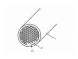
- the forward osmosis membrane member 4 in FIG. 6 is composed of a plurality of thin tubes (tubes having a shape like a straw) and a conduit that covers the outer periphery of the plurality of thin tubes.
- Each of the plurality of thin tubes is a treated fresh water passage 46, and the remaining portion other than the plurality of thin tubes is a concentrated salt water passage 45 inside the pipe.
- each of the plurality of thin tubes is a treated fresh water passage 45 and the remaining portion is a concentrated salt water passage 46.
- the reverse osmosis membrane member 3 discharges the concentrated salt water 51 and the fresh water 40 from the respective passages.
- the surface area of the reverse osmosis membrane is increased, so that the desalination ability of the reverse osmosis membrane member 3 is improved.
- the reverse osmosis membrane phenomenon has been described in various known literatures and is therefore omitted here.
- the reverse osmosis membrane member 3 obtains fresh water 40 from the salt water 30 by the mechanisms described in these various known documents.
- the reverse osmosis membrane member 3 generates the fresh water 40 from the salt water 30 and supplies the concentrated salt water 51 having a high salinity concentration to the forward osmosis membrane member 4.
- the forward osmosis membrane member 4 causes the water molecules from the treated fresh water 41 to permeate the concentrated salt water 51 by the forward osmosis membrane phenomenon described with reference to FIG. 4, thereby reducing the salt concentration of the concentrated salt water 51. Further, the forward osmosis membrane member 4 generates mixed water 52 by the permeation of water molecules from the treated fresh water 41 into the concentrated salt water 51. The forward osmosis membrane member 4 discharges this mixed water 52.
- the mixed water 52 has a salt concentration lower than that of the concentrated salt water 51 because water molecules from the treated fresh water 41 are added to the concentrated salt water 51. For this reason, even if the mixed water 52 is used after the forward osmosis membrane member 4, salt water having a high salinity concentration is not discarded, so that adverse effects on the environmental load can be prevented.
- the amount of water in the mixed water 52 is increased because water molecules are added to the concentrated salt water 51.
- the forward osmosis membrane member 4 can supply the auxiliary device 5 with the mixed water 52 with the increased amount of water while maintaining a constant pressure.
- the mixed water 52 can operate the auxiliary device 5.
- the auxiliary device 5 can reduce the load (power consumption) in the salt water supply means 2.
- FIG. 5 is a schematic diagram showing an example of a forward osmosis membrane member in the first embodiment.
- the forward osmosis membrane member 4 includes a concentrated salt water passage 45 and a treated fresh water passage 46 as shown in FIG. 5. Each is partitioned by a forward osmosis membrane 47.
- FIG. 6 is a structural cross-sectional view of the forward osmosis membrane member in the first embodiment.
- the forward osmosis membrane member 4 includes a plurality of thin tubes and a conduit that covers the thin tubes.
- Each of the plurality of capillaries is formed by a forward osmosis membrane, each of the plurality of capillaries is a treated fresh water passage 46, and the remaining portion of the conduit is a concentrated salt water passage 45.
- the forward osmosis membrane member 4 shown in FIGS. 5 and 6 is an example, and may have other configurations.
- the forward osmosis membrane phenomenon is as described in various known documents, and the explanation of the mechanism is omitted here.
- the auxiliary device 5 is supplied with the mixed water 52 that is generated and discharged by the forward osmosis membrane member 4.
- the mixed water 52 has a constant water amount and pressure.
- the auxiliary device 5 operates with this constant amount of water and pressure.
- the auxiliary device 5 is connected to the salt water supply means 2 in a power manner, and the energy generated by the operation of the auxiliary device 5 assists the operation of the salt water supply means 2.
- the auxiliary device 5 may have a power generation function, for example.
- the auxiliary device 5 has a turbine and a generator, and generates power by the amount and pressure of the supplied mixed water 52.
- the electric power generated by this power generation is supplied to the salt water supply means 2 to cover part of the electric power required by the salt water supply means 2. As a result, the power consumption of the salt water supply means 2 can be reduced.
- the auxiliary device 5 may have at least one of a pressure generation function and a pressure transmission function.
- the auxiliary device 5 is composed of pressure conversion means (such as a pressure changer), converts the pressure of the supplied mixed water 52 into the pressure of the salt water supply means 2, and contributes to the pressure increase of the salt water supply means 2. To do. As a result, the power consumption of the salt water supply means 2 can be reduced.
- the auxiliary device 5 may have a rotation providing function.
- the auxiliary device 5 has a rotating member connected to the rotating shaft of the salt water supply means 2, and the rotating member rotates based on the amount and pressure of the supplied mixed water 52.
- the rotation of the rotating member can increase at least one of the number of rotations and the rotational force in the salt water supply means 2 by the rotating shaft to be connected. As a result, the power consumption of the salt water supply means 2 can be reduced.
- the auxiliary device 5 uses at least one of the amount of water and the pressure of the mixed water 52 to assist the load of the salt water supply unit 2 and contributes to reduction of power consumption and energy consumption of the salt water supply unit 2. .
- the auxiliary device 5 discharges the used mixed water 52.
- the discharge is finally performed in sewage, rivers, lakes, and the sea, the mixed water 52 has a lower salt concentration than the concentrated salt water 51. For this reason, unlike the case described in the reference technology, it is possible to reduce the environmental load due to the discharge of concentrated salt water having a high salt concentration.
- the salt water desalination apparatus 1 can reduce the environmental load in combination with the reduction of electric power required by the salt water supply means 2 and the decrease in the salinity concentration of the discharged waste water.
- FIG. 7 is a block diagram of a saltwater desalination apparatus according to Variation 1 of Embodiment 2 of the present invention.
- the basic concept and configuration of the saltwater desalination apparatus 1A is the same as that of the saltwater desalination apparatus 1 described in the first embodiment.
- the auxiliary device 5 is the rotation auxiliary member 501.
- the salt water supply means 2 is a salt water supply pump 201 that supplies salt water by rotating along the rotation axis.
- the rotation auxiliary member 501 has a rotation shaft, and this rotation shaft is directly connected to the rotation shaft of the salt water supply pump 201.
- the rotation auxiliary member 501 receives the mixed water 52 supplied from the forward osmosis membrane member 4 and rotates. Since the mixed water 52 has a constant water amount and pressure, the rotation assisting member 501 can be rotated. In accordance with this rotation, the rotation shaft of the rotation auxiliary member 501 also rotates.
- the rotation auxiliary member 501 has an impeller connected to the rotation shaft, and the mixed water 52 collides with the impeller to rotate the impeller. Naturally, the rotating shaft also rotates due to the rotation of the impeller.
- the rotation shaft of the rotation auxiliary member 501 is directly connected to the rotation shaft of the salt water supply pump 201.
- at least one of the rotational speed and rotational force of the salt water supply pump 201 increases. If at least one of the rotational speed and the rotational force increases, the supply capacity of the salt water 30 of the salt water supply pump 201 increases. In other words, if the same salt water supply capability is acceptable, the electric power and energy required by the salt water supply pump 201 itself excluding the rotation auxiliary member 501 can be reduced by rotation assistance from the rotation auxiliary member 501.
- the mixed water 52 has a constant water amount and pressure, it is easy to rotate the rotation auxiliary member 501 having an impeller and the like. It is easy to add the rotation of the rotation assisting member 501 to the rotation of the salt water supply pump 201. As a result, the load on the salt water supply pump 201 is reduced, and power consumption and energy consumption are reduced.
- the mixed water 52 supplied to the rotation of the rotation assisting member 501 is released, but since the salt concentration is reduced in the forward osmosis membrane member 4, the environmental load due to the released mixed water 52 is small.
- FIG. 8 is a block diagram of a saltwater desalination apparatus corresponding to variation 2 in Embodiment 2 of the present invention.
- the salt water desalination apparatus 1B is the same idea as the variation 1 in using the mixed water 52 obtained by diluting the concentrated salt water 51 discharged from the reverse osmosis membrane member 3 using the forward osmosis membrane member 4. .
- the salt water supply means 2 uses the salt water supply pump 201 that supplies the salt water 30 by rotating based on the rotation shaft, similarly to the salt water desalination apparatus 1A of Variation 1.
- the salt water 30 is supplied to the reverse osmosis membrane member 3 via the pump 23 and the pressure converting means 6 through a route (in parallel) different from the salt water supply pump 201.
- the pressure conversion means 6 increases the pressure of the salt water 30 supplied from the pump 23 using the concentrated salt water 51 released from the reverse osmosis membrane member 3.
- the pressure conversion means 6 has a role of increasing the pressure of a liquid traveling in a certain path, known as a pressure changer, by the pressure of another liquid supplied from another path. For this reason, the concentrated salt water 51 whose salinity concentration and pressure increased by the reverse osmosis membrane member 3 is supplied to the pressure converting means 6. The pressure of the concentrated salt water 51 increases the pressure of the salt water 30 supplied from the pump 23, and the salt water 30 is supplied to the reverse osmosis membrane member 3.
- the salt water desalination apparatus 1B can reduce the power consumption and energy consumption of the salt water supply pump 201, which is the salt water supply means 2, by paralleling the salt water supply.
- the concentrated salt water 51 having the same salt concentration is supplied to the forward osmosis membrane member 4 by the pump 21.
- the forward osmosis membrane member 4 generates mixed water 52 by the forward osmosis membrane phenomenon with respect to the treated fresh water 41 and the concentrated salt water 51 supplied separately. For this reason, even if the concentrated salt water 51 supplied to the forward osmosis membrane member 4 does not have a high pressure, the mixed water 52 can be generated by the forward osmosis membrane phenomenon as long as it has a high salt concentration.
- the mixed water 52 is generated by infiltration of water molecules from the treated fresh water into the concentrated salt water 51. For this reason, the forward osmosis membrane member 4 can discharge the mixed water 52 having a larger amount of water than the concentrated salt water 51.
- the pump 21 generates a predetermined pressure, and the concentrated salt water 51 is supplied to the forward osmosis membrane member 4.
- the pump 21 supplies the concentrated salt water 51 to the forward osmosis membrane member 4 without stagnation, and the forward osmosis membrane member 4 generates and releases mixed water 52 having a larger amount of water than the concentrated salt water 51 by the forward osmosis membrane phenomenon. To do.
- the mixed water 52 having this amount of water and pressure can rotate the rotation auxiliary member 501.
- the rotation auxiliary member 501 has a rotation shaft connected to the rotation shaft of the salt water supply pump 2, and the rotation of the rotation auxiliary member 501 can assist the rotation of the salt water supply pump 201.
- the effect of this assistance is the same as that described in the salt water desalination apparatus 1A in Variation 1.
- the concentrated salt water 51 that has lost pressure by being used in the pressure converting means 6 passes through the forward osmosis membrane member 4 to operate the rotation auxiliary member 501 again to assist the rotation of the salt water supply pump 201. it can.
- the rotation auxiliary member 501 can reduce the power consumption and energy consumption of the salt water supply pump 201.
- the salt water desalination apparatus 1B corresponding to the variation 2 first divides the supply path of the salt water 30 from the salt water source to the reverse osmosis membrane member 3 in parallel, and then in one supply path.
- the concentrated salt water 51 released from the reverse osmosis membrane member 3 is used for increasing the pressure.
- the load (power consumption and energy consumption) of the salt water supply pump 201 which is the main element of the salt water supply means 2 can be reduced.
- the forward osmosis membrane member 4 utilizes the salinity concentration of the concentrated salt water 51 that has lost pressure in the pressure converting means 6 to cause the rotation auxiliary member 501 to rotate.
- the rotation of the rotation auxiliary member 501 can further reduce the load (power consumption and energy consumption) of the salt water supply pump 201 which is the main element of the salt water supply means 2.
- the power consumption and energy consumption of the salt water supply means 2 can be further reduced. become.
- the mixed water 52 that is finally discharged and discharged has a reduced salinity, and therefore, it is the same as in the first embodiment and variation 1 that the environmental load is less likely to deteriorate.
- FIG. 9 is a block diagram of a salt water desalination apparatus corresponding to Variation 3 in Embodiment 2 of the present invention.
- the salt water desalination apparatus 1 ⁇ / b> C further includes another pressure conversion means 61 in a path through which the concentrated salt water 51 reaches the forward osmosis membrane member 4 from the pressure conversion means 6. ing.
- the configuration and basic idea are the same as the salt water desalination apparatus 1B corresponding to the variation 2 except that this pressure conversion means 61 is further provided. That is, the path for supplying the salt water 30 to the reverse osmosis membrane member 3 is parallelized to reduce the power consumption and energy consumption of the salt water supply pump 201. In addition, the pressure of the concentrated salt water 51 released from the reverse osmosis membrane member 3 is used once by the pressure conversion means 6 to reduce the power consumption and energy consumption of the salt water supply pump 201.
- the concentrated salt water 51 that has lost its pressure in the pressure converting means 6 is reused in the forward osmosis membrane member 4 to rotate the rotation assisting member 501 as an assisting device, so that the power consumption and consumption of the saltwater supply pump 201 are increased. Reduce energy.
- a pressure converting means 61 is provided between the pressure converting means 6 and the forward osmosis membrane member 4.
- a pump 21 is provided upstream of the pressure conversion means 61, and the concentrated salt water 51 used for increasing the pressure of the salt water 30 by the pressure conversion means 6 is supplied to the pressure conversion means 61 by the pump 21.
- the pump 21 can increase the pressure to the extent that the concentrated salt water 51 is supplied to the pressure conversion means 61. However, if the pump 21 is operated to further increase the pressure, the power consumption and energy consumption of the pump 21 increases, and the salt water desalination apparatus 1C. It is not suitable for the purpose of reducing the overall power consumption. For this reason, the concentrated salt water 51 supplied to the pressure conversion means 61 by the pump 21 is only a pressure of the supplied level.
- the mixed water 52 produced by the forward osmosis membrane member 4 is supplied to the pressure converting means 61.
- the mixed water 52 generated by the forward osmosis membrane member 4 has an increased amount of water, based on the pressure of the concentrated salt water 51 supplied to the forward osmosis membrane member 4.
- the mixed water 52 having increased pressure is supplied to the pressure converting means 61 through a separate supply path, whereby the pressure of the concentrated salt water 51 from the pump 21 supplied to the main flow of the pressure converting means 61 is increased, and the pressure is increased. It is discharged from the conversion means 61. That is, the pressure of the concentrated salt water 51 supplied to the forward osmosis membrane member 4 is increased.
- the pressure of the concentrated salt water 51 supplied to the forward osmosis membrane member 4 is high, the energy of the mixed water 52 released by the forward osmosis membrane member 4 increases. This is because the energy is indicated by multiplication of the pressure and the amount of water, and the energy of the mixed water 52 released from the forward osmosis membrane member 4 is increased when the pressure is increased and supplied.
- the salt water desalination apparatus 1C of Variation 3 shown in FIG. 9 has the merit of increasing the ability of the rotation assisting member 501 by increasing the energy of the mixed water 52 supplied from the forward osmosis membrane member 4 to the rotation assisting member 501. Cause it to occur.
- the pressure conversion means 61 is more energy efficient than the rotation assisting member 501. As described above, the pressure converting means 61 can increase the energy of the mixed water 52 released by the forward osmosis membrane member 4 by increasing the pressure of the concentrated salt water 51.
- a part of the mixed water 52 is supplied to the pressure converting means 61, and the energy of the mixed water 52 can be increased efficiently. Since a part of the mixed water 52 with increased energy is used in the rotation assisting member 501, the power consumption and energy consumption of the salt water supply pump 201 by the rotation assisting member 501 can be reduced. In this case, the merit which can reduce the energy consumption of the pump 21 which gives a pressure to the concentrated salt water 51 which the reverse osmosis membrane member 3 discharge
- the salt water desalination apparatus 1C corresponding to the variation 3 distributes the mixed water 52 discharged from the forward osmosis membrane member 4 to the rotation assisting member 501 and the pressure converting means 61, so that the salt water supply pump 201 and the pump 21 The purpose is to reduce each energy consumption in a balanced manner.
- FIG. 10 is a block diagram of a saltwater desalination apparatus corresponding to variation 4 in Embodiment 2 of the present invention.
- the saltwater desalination apparatus 1D has the same concept and configuration as the saltwater desalination apparatus 1C corresponding to the variation 3.
- it has a pressure conversion means 6 that receives the concentrated salt water 51 discharged from the reverse osmosis membrane member 3, which is a subsequent stage of the reverse osmosis membrane member 3.
- This pressure converting means 6 is a parallel path for supplying the salt water 30 using the pressure of the concentrated salt water 51 as described in the salt water desalination apparatus 1B in variation 2 and the salt water desalination apparatus 1C in variation 3. Increase ability.
- the concentrated salt water 51 loses its pressure almost due to the pressure increase in the pressure converting means 6, but remains a high salt concentration.
- the concentrated salt water 51 is used in the forward osmosis membrane member 4. At this time, the concentrated salt water 51 is not supplied to the forward osmosis membrane member 4 as it is, but is supplied via the pressure converting means 61 described in the salt water desalination apparatus 1C.
- the pressure converting means 61 receives a part of the mixed water 52 discharged from the forward osmosis membrane member 4 (having a water amount and pressure higher than the amount and pressure of the concentrated salt water 51 entering the forward osmosis membrane member 4), and pressure The pressure of the concentrated salt water 51 supplied to the conversion means 61 is increased.
- the pressure of the concentrated salt water 51 is increased by the pressure converting means 61, the pressure of the concentrated salt water 51 supplied to the forward osmosis membrane member 4 is increased.
- the energy of the mixed water 52 in the forward osmosis membrane member 4 is improved. That is, the forward osmosis membrane member 4 can generate and release the mixed water 52 with increased energy by the amount of pressure increased by the pressure converting means 61.
- the salt water desalination apparatus 1C in Variation 3 supplies the mixed water 52 discharged from the forward osmosis membrane member 4 to a rotation auxiliary member 501 as an auxiliary device for assisting the salt water supply pump 201.
- the salt water desalination apparatus 1D in Variation 4 shown in FIG. 10 supplies the mixed water 52 released from the forward osmosis membrane member 4 to the pressure conversion means 502 as an auxiliary device.
- the pressure conversion means 502 is provided downstream of the salt water supply pump 201.
- the salt water supply pump 201 supplies the salt water 30 to the reverse osmosis membrane member 3. At this time, it is necessary to supply the salt water 30 in an amount and pressure matched to the reverse osmosis membrane phenomenon ability of the reverse osmosis membrane member 3. For this reason, the salt water supply pump 201 is required to be supplied with the necessary amount and pressure.
- the pressure conversion means 502 can assist.
- the pressure conversion means 502 increases the pressure of the salt water 30 flowing from the salt water supply pump 201 using the mixed water 52 supplied from the forward osmosis membrane member 4. That is, the pressure conversion means 502 can be further added to the pressure increase in the salt water supply pump 201.
- the pressure converting means 502 further increases the pressure to the pressure increased by the salt water supply pump 201, and the salt water 30 is supplied to the reverse osmosis membrane member 3.
- the pressure converting means 502 can reduce the load of pressure increase required for the salt water supply pump 201 in the supply of the salt water 30 through the supply route of the salt water supply pump 201. As a result, the power consumption and energy consumption of the salt water supply pump 201 can be reduced.
- the pump 26 compensates for the shortage of power recovery by the pressure conversion means 502.
- the power consumption and energy consumption of the salt water supply means 2 that mainly bears the power consumption and energy consumption in the salt water desalination apparatus 1D can be reduced. Also in this point, the salt water desalination apparatus 1D corresponding to the variation 4 can reduce the environmental load. In addition, since the mixed water 52 that is collected and discharged as a sample has a low salinity, the environmental load can be reduced in this respect as well.
- FIG. 11 is a block diagram of salt water desalination apparatus 1 corresponding to variation 5 in Embodiment 2 of the present invention.
- the salt water desalination apparatus 1E has substantially the same configuration as the salt water desalination apparatus 1D corresponding to the variation 4 described with reference to FIG. 10, and the salt water supply pump as the salt water supply means 2 is the same as the salt water supply pump 201. It is divided in parallel with the salt water supply pump 202. Furthermore, the pump 23 also serves as a part of the salt water supply pump.
- a pressure conversion means 502 that increases the pressure of salt water supplied from the salt water supply pump 201 by the mixed water 52 is provided in the subsequent stage of the salt water supply pump 201. As a result, the load on the salt water supply pump 201 is reduced.
- the salt water supply pump 202 in parallel with the salt water supply pump 201, it is possible to divide the burden of supplying the salt water 30 from the salt water source to the reverse osmosis membrane member 3. As a result, the load on the salt water supply pump 201 is reduced.
- the salt water supply means 2 is the total of the salt water supply pump 201 and the salt water supply pump 202. However, by dividing, the total power consumption and energy consumption of the two pumps can be reduced as compared with a case where the two are alone. .
- the pressure conversion means 502 using the mixed water 52 can reduce the power consumption and energy consumption of the salt water supply pump 201.
- the pump 202 can easily control the amount of salt water flowing into the reverse osmosis membrane member 3.
- the salt water supply pump is configured as a single unit, it may be difficult to control the amount of salt water supplied to the reverse osmosis membrane member 3.
- the amount of salt water supplied to the reverse osmosis membrane member 3 is related to the amount of concentrated salt water 51 to be generated, and the amount of concentrated salt water 51 is generated by the forward osmosis membrane member 4 and used in the subsequent auxiliary device and the like. This is related to the amount of mixed water 52 produced.
- the production amount of the mixed water 52 is related to the balance of the distribution amount to the subsequent auxiliary device and other pressure conversion means 61. If this balance is not achieved, the design of the entire salt water desalination apparatus 1E may be difficult. is there.
- Variation 5 saltwater desalination apparatus 1E having such a configuration can control the overall operation to an appropriate balance while controlling the supply of saltwater.
- the salt water desalination apparatus 1E corresponding to Variation 5 can reduce power consumption and energy consumption, and can reduce running costs.
- each of the salt water desalination apparatuses 1A to 1E based on various variations described in the second embodiment can reduce the running cost. As a result, the spread of the saltwater desalination apparatus can be promoted.
- Embodiments 1 and 2 are examples for explaining the gist of the present invention, and includes modifications and alterations without departing from the gist of the present invention.
Landscapes
- Engineering & Computer Science (AREA)
- Water Supply & Treatment (AREA)
- Chemical & Material Sciences (AREA)
- Chemical Kinetics & Catalysis (AREA)
- Life Sciences & Earth Sciences (AREA)
- Hydrology & Water Resources (AREA)
- Environmental & Geological Engineering (AREA)
- Organic Chemistry (AREA)
- Nanotechnology (AREA)
- Separation Using Semi-Permeable Membranes (AREA)
Abstract
Description
図1は、逆浸透膜を用いた一般的な塩水淡水化装置のブロック図である。塩水淡水化装置100は、塩水供給手段110と逆浸透膜部材120を有している。塩水供給手段110は、塩水101を逆浸透膜部材120に供給する。逆浸透膜部材は、塩水通路と淡水通路とに分離されており、供給される塩水の圧力を受けて、塩水通路の塩水から逆浸透膜を通じて水分子を淡水通路にしみださせる。この結果、逆浸透膜部材120は、淡水102と、塩分濃度が上昇した濃縮塩水103と、を放出する。
まず、本発明の実施の形態1における塩水淡水化装置の概要について説明する。図3は、本発明の実施の形態1における塩水淡水化装置のブロック図である。図4は、本発明の実施の形態1における正浸透膜部材の模式図である。
塩水供給手段2は、塩水供給ポンプなど、海中、湖中など天然もしくは人工の塩水源から、塩水を吸い上げて、塩水淡水化装置1に供給する。特に、塩水供給手段2は、逆浸透膜部材3に塩水を供給する。もちろん、塩水淡水化装置1の構成によっては、塩水供給手段2と逆浸透膜部材3との間に他の要素が介在する場合もありえる。この場合でも、塩水供給手段2は、逆浸透膜部材3に塩水を最終的に供給することを目的とする。
また、塩水供給手段2は、逆浸透膜部材3に塩水を供給する主たる要素である。このため、例えば後述する他の構成を有する塩水淡水化装置において、塩水供給手段2にパラレルとなる他の供給手段が設けられてもよい。この場合には、塩水供給手段2が、逆浸透膜部材3に塩水を供給する負担が減少する。言い換えれば、パラレルに設けられる複数の供給手段が、逆浸透膜部材3に、必要となる塩水を供給する。
塩水淡水化装置1は、設置される塩水源の特性、地形特性、淡水需要量、設置資金などによって、様々な大きさのものが、様々な場所に設置される。場合によっては、淡水需要量は多いが、電気インフラの不十分さによって、淡水需要量をまかなえるだけの大きさの塩水淡水化装置1が設置できないこともある。
後述する、塩水淡水化装置1の他の構成においても、図3を用いて説明した実施の形態1における塩水淡水化装置1の構成においても、複数のポンプが設けられる。これらポンプは、例えば逆浸透膜部材3、正浸透膜部材4、補助デバイス5、圧力変換手段などの、塩水淡水化装置1を構成する種々の要素に塩水、濃縮塩水、淡水が供給される場合に、設けられる。すなわち、種々の要素を介在させる部材である。
逆浸透膜部材3は、供給される塩水30を、逆浸透膜による逆浸透膜現象によって、塩水30から水分子を浸透させて、淡水40を生成して放出する。これに合わせて、水分子が減少した塩水は、塩分濃度の増加した濃縮塩水51として、逆浸透膜部材3から放出される。濃縮塩水51は、また、圧力を有している。この高くなった塩分濃度と圧力を有する濃縮塩水51を、逆浸透膜部材3は、正浸透膜部材4に供給する。
正浸透膜部材4は、図4を用いて説明した正浸透膜現象によって、濃縮塩水51に処理淡水41からの水分子を浸透させて、濃縮塩水51の塩分濃度を低下させる。また、正浸透膜部材4は、濃縮塩水51に処理淡水41からの水分子の浸透によって、混合水52を生成する。正浸透膜部材4は、この混合水52を放出する。混合水52は、濃縮塩水51に処理淡水41からの水分子が付与されているので、濃縮塩水51よりも、塩分濃度が低い。このため、正浸透膜部材4以降で、混合水52が利用されるとしても、塩分濃度の高い塩水が、廃棄されることが無いので、環境負荷への悪影響が防止できる。
補助デバイス5は、正浸透膜部材4で生成されて放出される混合水52の供給を受ける。混合水52は、一定の水量および圧力を有している。補助デバイス5は、この一定の水量と圧力によって動作する。また補助デバイス5は、塩水供給手段2に動力的に接続しており、補助デバイス5の動作で生じるエネルギーは、塩水供給手段2の動作を補助する。
次に実施の形態2について説明する。実施の形態2では、塩水淡水化装置の様々なバリエーションについて説明する。
図7は、本発明の実施の形態2におけるバリエーション1での塩水淡水化装置のブロック図である。塩水淡水化装置1Aは、基本的な考え方および構成は、実施の形態1で説明した塩水淡水化装置1と同様である。
図8は、本発明の実施の形態2におけるバリエーション2に対応する塩水淡水化装置のブロック図である。塩水淡水化装置1Bは、正浸透膜部材4を用いて、逆浸透膜部材3から放出される濃縮塩水51を薄めて得られる混合水52を利用する点では、バリエーション1と同様の思想である。
バリエーション2に対応する塩水淡水化装置1Bは、逆浸透膜部材3への塩水30の供給が並列化されている。塩水供給手段2は、バリエーション1の塩水淡水化装置1Aと同じく、回転軸に基づいて回転することで塩水30を供給する塩水供給ポンプ201を用いる。
圧力変換手段6は、濃縮塩水51の圧力を利用するだけであるので、圧力変換手段6で使用された濃縮塩水51の圧力は、ほぼ消失した状態となって、圧力変換手段6から放出される。一方、濃縮塩水51の塩分濃度はそのままで、圧力変換手段6から放出される。
以上、説明したように、バリエーション2に対応する塩水淡水化装置1Bは、まず塩水源からの塩水30の、逆浸透膜部材3への供給路をパラレルに分けた上で、一方の供給路である圧力変換手段6では、逆浸透膜部材3から放出される濃縮塩水51を、圧力増加に利用している。この処理により、塩水供給手段2の主要素である塩水供給ポンプ201の負荷(消費電力や消費エネルギー)が低減できる。加えて、圧力変換手段6で圧力を失った濃縮塩水51の塩分濃度を、正浸透膜部材4が活用して回転補助部材501の回転を生じさせる。この回転補助部材501の回転は、塩水供給手段2の主要素である塩水供給ポンプ201の負荷(消費電力や消費エネルギー)が、更に低減できる。
次に、バリエーション3での塩水淡水化装置について説明する。
圧力変換手段61が圧力変換手段6と正浸透膜部材4との間に設けられる。圧力変換手段61の前段には、ポンプ21が設けられて、圧力変換手段6で塩水30の圧力を増加させるのに用いられた濃縮塩水51が、ポンプ21によって圧力変換手段61に供給される。
次に、バリエーション4に対応する塩水淡水化装置について説明する。図10は、本発明の実施の形態2におけるバリエーション4に対応する塩水淡水化装置のブロック図である。塩水淡水化装置1Dは、バリエーション3に対応する塩水淡水化装置1Cと同様の思想および構成を有している。例えば、逆浸透膜部材3の後段であって、逆浸透膜部材3から放出される濃縮塩水51を受ける圧力変換手段6を有している。この圧力変換手段6は、バリエーション2での塩水淡水化装置1Bやバリエーション3での塩水淡水化装置1Cで説明したように、濃縮塩水51の圧力を利用して、塩水30を供給するパラレル経路の能力を高める。
次に、バリエーション5に対応する塩水淡水化装置について説明する。図11は、本発明の実施の形態2におけるバリエーション5に対応する塩水淡水化装置1のブロック図である。塩水淡水化装置1Eは、図10を用いて説明したバリエーション4に対応する塩水淡水化装置1Dとほぼ同じ構成を有しており、塩水供給手段2としての塩水供給ポンプが、塩水供給ポンプ201と塩水供給ポンプ202とにパラレルに分割されている。さらには、ポンプ23も塩水供給ポンプの一部を担う。
2 塩水供給手段
21、22、23、24、25、26 ポンプ
201、202 塩水供給ポンプ
3 逆浸透膜部材
4 正浸透膜部材
5 補助デバイス
501 回転補助部材
502 圧力変換手段
6 圧力変換手段
30 塩水
40 淡水
41 処理淡水
51 濃縮塩水
52 混合水
100 塩水淡水化装置
101 塩水
102 淡水
110 塩水供給手段
120 逆浸透膜部材
Claims (13)
- 塩水を逆浸透膜部材に供給する塩水供給手段と、
前記逆浸透膜部材から放出される濃縮塩水が供給される正浸透膜部材と、
前記正浸透膜部材から放出される混合水が供給されると共に、前記塩水供給手段に接続する補助デバイスと、を備え、
前記補助デバイスは、前記塩水供給手段への供給電力、前記塩水供給手段への付与圧力および前記塩水供給手段への回転能力の少なくとも一つを増加させる、塩水淡水化装置。 - 前記塩水供給手段は、塩水供給ポンプである、請求の範囲第1項記載の塩水淡水化装置。
- 前記逆浸透膜部材は、前記塩水供給手段より供給される塩水が導入されて通る塩水通路と、膜での逆浸透現象によって前記塩水の塩分が除去された淡水が通る淡水通路と、を有し、前記塩水通路から前記濃縮塩水を放出し、前記淡水通路から前記淡水を供給する、請求の範囲第1項または第2項記載の塩水淡水化装置。
- 前記正浸透膜部材には、前記濃縮塩水が供給されて通る濃縮塩水通路と、処理淡水が供給されて通る処理淡水通路と、を有し、
前記処理淡水通路から前記濃縮塩水通路に、正浸透現象によって、水分子が移動し、前記正浸透膜部材は、混合水を生成して、前記補助デバイスに出力する、請求の範囲第1項から第3項のいずれか記載の塩水淡水化装置。 - 前記混合水は、前記濃縮塩水よりも塩分濃度が低い、請求の範囲第4項記載の塩水淡水化装置。
- 前記混合水は、前記濃縮塩水よりも高い水量および高いエネルギーの少なくとも一方を有する、請求の範囲第4項または第5項記載の塩水淡水化装置。
- 前記塩水供給手段が、回転軸に沿って回転することで塩水を供給する塩水供給ポンプである場合に、
前記補助デバイスは、前記回転軸に連結して、前記塩水供給ポンプの回転数および回転力の少なくとも一方を増加させる回転補助部材を有する、請求の範囲第1項から第6項のいずれか記載の塩水淡水化装置。 - 前記回転補助部材は、供給される前記混合水の圧力によって回転力を生じさせて、連結する前記回転軸を通じて、前記塩水供給ポンプの回転数および回転力の少なくとも一方を増加させる、請求の範囲第7項記載の塩水淡水化装置。
- 前記塩水供給手段が、電力によって動作する塩水供給ポンプである場合に、
前記補助デバイスは、前記塩水供給ポンプに供給される補助電力を生成する電力生成部を有し、
前記塩水供給ポンプは、前記補助電力も利用して動作する、請求の範囲第1項から第6項のいずれか記載の塩水淡水化装置。 - 前記混合水は、その圧力によって、前記電力生成部の有するタービンを回転させる、請求の範囲第9項記載の塩水淡水化装置。
- 前記補助デバイスは、前記塩水供給手段に接続する第2圧力変換手段を有し、
前記第2圧力変換手段は、前記混合水を受けて、前記塩水供給手段に入力する前記塩水の圧力を増加させ、
前記第2圧力変換手段は、圧力が増加された前記塩水を、前記逆浸透膜部材に供給する、請求の範囲第1項から第6項のいずれか記載の塩水淡水化装置。 - 前記正浸透膜部材の前段に、第3圧力変換手段を更に備え、
前記第3圧力変換手段は、供給される前記濃縮塩水の圧力を、前記正浸透膜部材から放出される前記混合水を用いて、増加させる、請求の範囲第1項から第11項のいずれか記載の塩水淡水化装置。 - 塩水源から前記逆浸透膜部材に前記塩水を供給する前記塩水供給手段は、複数の経路に分割されて前記塩水を、前記逆浸透膜部材に供給し、
前記複数の経路の一部は、第1圧力変換手段を有し、
前記逆浸透膜部材は、前記濃縮塩水を、前記第1圧力手段に供給して、前記第1圧力変換手段は、前記濃縮塩水の有する圧力に基づいて、前記逆浸透膜部材に供給する前記塩水の圧力を増加させ、
前記第1圧力変換手段は、圧力増加に用いた前記濃縮塩水を、前記正浸透膜部材に供給する、請求の範囲第1項から第12項のいずれか記載の塩水淡水化装置。
Priority Applications (6)
| Application Number | Priority Date | Filing Date | Title |
|---|---|---|---|
| AU2014247832A AU2014247832B2 (en) | 2013-04-02 | 2014-01-29 | Salt water desalination device |
| ES14780118T ES2899165T3 (es) | 2013-04-02 | 2014-01-29 | Dispositivo de desalinización de agua salada |
| US14/760,087 US9751046B2 (en) | 2013-04-02 | 2014-01-29 | Salt water desalination equipment |
| EP14780118.7A EP2982654B1 (en) | 2013-04-02 | 2014-01-29 | Salt water desalination device |
| IL239729A IL239729B (en) | 2013-04-02 | 2015-06-30 | Device for desalination of salt water |
| SA515361254A SA515361254B1 (ar) | 2013-04-02 | 2015-10-01 | معدات تحلية ماء مالح |
Applications Claiming Priority (2)
| Application Number | Priority Date | Filing Date | Title |
|---|---|---|---|
| JP2013-076514 | 2013-04-02 | ||
| JP2013076514A JP6192336B2 (ja) | 2013-04-02 | 2013-04-02 | 塩水淡水装置 |
Publications (1)
| Publication Number | Publication Date |
|---|---|
| WO2014162763A1 true WO2014162763A1 (ja) | 2014-10-09 |
Family
ID=51658069
Family Applications (1)
| Application Number | Title | Priority Date | Filing Date |
|---|---|---|---|
| PCT/JP2014/051873 Ceased WO2014162763A1 (ja) | 2013-04-02 | 2014-01-29 | 塩水淡水化装置 |
Country Status (8)
| Country | Link |
|---|---|
| US (1) | US9751046B2 (ja) |
| EP (1) | EP2982654B1 (ja) |
| JP (1) | JP6192336B2 (ja) |
| AU (1) | AU2014247832B2 (ja) |
| ES (1) | ES2899165T3 (ja) |
| IL (1) | IL239729B (ja) |
| SA (1) | SA515361254B1 (ja) |
| WO (1) | WO2014162763A1 (ja) |
Cited By (1)
| Publication number | Priority date | Publication date | Assignee | Title |
|---|---|---|---|---|
| WO2016080085A1 (ja) * | 2014-11-19 | 2016-05-26 | 東洋紡株式会社 | 造水システムおよび造水方法 |
Families Citing this family (24)
| Publication number | Priority date | Publication date | Assignee | Title |
|---|---|---|---|---|
| JP6437529B2 (ja) * | 2014-03-27 | 2018-12-12 | 株式会社荏原製作所 | エネルギー回収システム |
| JP2016097331A (ja) * | 2014-11-19 | 2016-05-30 | 東洋紡株式会社 | 造水システムおよび造水方法 |
| JP2016160512A (ja) * | 2015-03-04 | 2016-09-05 | 株式会社東芝 | 電解装置及び無機塩化物水溶液カートリッジ |
| JP6600499B2 (ja) * | 2015-07-29 | 2019-10-30 | 株式会社クボタ | 塩水淡水化装置及び塩水淡水化装置の改造方法 |
| JP6159371B2 (ja) * | 2015-08-25 | 2017-07-05 | 協和機電工業株式会社 | エネルギー生成装置用の制御装置 |
| GB201605068D0 (en) * | 2016-03-24 | 2016-05-11 | Applied Biomimetic As | Electricity generation process |
| GB201605070D0 (en) | 2016-03-24 | 2016-05-11 | Applied Biomimetic As | Power generation process |
| AU2017228930B2 (en) * | 2016-03-09 | 2023-03-16 | Enrgistream Pty Ltd | Process and system for treating waste water and generating power |
| JP6658198B2 (ja) * | 2016-03-28 | 2020-03-04 | 東洋紡株式会社 | 造水システム |
| JP6658199B2 (ja) * | 2016-03-28 | 2020-03-04 | 東洋紡株式会社 | 造水システム |
| GB201711240D0 (en) | 2017-07-12 | 2017-08-23 | Saltkraft Aps | Power generation process |
| GB201711238D0 (en) | 2017-07-12 | 2017-08-23 | Saltkraft Aps | Power generation process |
| CN109553202A (zh) * | 2017-09-26 | 2019-04-02 | 北京天诚同创电气有限公司 | 反渗透海水淡化方法、系统及系统的控制方法 |
| US10766002B2 (en) * | 2019-02-04 | 2020-09-08 | Fluid Equipment Development Company, Llc | Method and system for performing reverse osmosis with brine recirculation and energy recovery |
| CA3143592A1 (en) * | 2019-06-20 | 2020-12-24 | Conocophillips Company | Water injection into a hydrocarbon reservoir |
| US10940439B1 (en) * | 2019-12-10 | 2021-03-09 | Kuwait Institute For Scientific Research | High water recovery hybrid membrane system for desalination and brine concentration |
| JP7787384B2 (ja) * | 2020-09-18 | 2025-12-17 | サステイナブル・ウォーター・パワー・コンサルタンツ・エフゼット・エルエルシー | 海水淡水化システム |
| US11502322B1 (en) | 2022-05-09 | 2022-11-15 | Rahul S Nana | Reverse electrodialysis cell with heat pump |
| US11502323B1 (en) | 2022-05-09 | 2022-11-15 | Rahul S Nana | Reverse electrodialysis cell and methods of use thereof |
| ES2992338T3 (es) * | 2022-06-08 | 2024-12-11 | Danfoss As | Sistema de ósmosis inversa y de ósmosis retardada por presión |
| CN115614209A (zh) * | 2022-10-12 | 2023-01-17 | 中煤科工集团南京设计研究院有限公司 | 一种余压发电系统及方法 |
| US12040517B2 (en) | 2022-11-15 | 2024-07-16 | Rahul S. Nana | Reverse electrodialysis or pressure-retarded osmosis cell and methods of use thereof |
| US11855324B1 (en) | 2022-11-15 | 2023-12-26 | Rahul S. Nana | Reverse electrodialysis or pressure-retarded osmosis cell with heat pump |
| JP2025538227A (ja) | 2022-11-15 | 2025-11-26 | エス ナナ,ラフル | 逆電気透析または圧力遅延浸透セルおよびその使用方法 |
Citations (9)
| Publication number | Priority date | Publication date | Assignee | Title |
|---|---|---|---|---|
| JPH01123605A (ja) * | 1987-11-06 | 1989-05-16 | Nkk Corp | 逆浸透膜を用いた塩水淡水化設備のエネルギー回収方法 |
| JP2003176775A (ja) * | 2001-12-10 | 2003-06-27 | Tokyo Inst Of Technol | 海水淡水化装置付き浸透圧発電システム |
| JP2005279540A (ja) * | 2004-03-30 | 2005-10-13 | Toray Eng Co Ltd | 淡水化装置 |
| JP2011083741A (ja) * | 2009-10-19 | 2011-04-28 | Kyb Co Ltd | 海水淡水化装置 |
| WO2012002263A1 (ja) * | 2010-06-28 | 2012-01-05 | 協和機電工業株式会社 | 中空糸型正浸透膜 |
| JP2012096151A (ja) | 2010-11-01 | 2012-05-24 | Ebara Corp | 海水淡水化システムおよびエネルギー交換チャンバー |
| JP2012192379A (ja) | 2011-03-17 | 2012-10-11 | Toshiba Corp | 海水淡水化装置およびその制御方法 |
| JP2012250200A (ja) | 2011-06-06 | 2012-12-20 | Hitachi Ltd | 正浸透膜を用いた海水淡水化システム |
| WO2013140848A1 (ja) * | 2012-03-19 | 2013-09-26 | 株式会社 東芝 | 海水淡水化装置 |
Family Cites Families (8)
| Publication number | Priority date | Publication date | Assignee | Title |
|---|---|---|---|---|
| JP2000167358A (ja) | 1998-12-08 | 2000-06-20 | Nitto Denko Corp | 膜分離システムおよび膜分離方法 |
| US20100192575A1 (en) * | 2007-09-20 | 2010-08-05 | Abdulsalam Al-Mayahi | Process and systems |
| AU2010325544B2 (en) * | 2009-11-25 | 2014-12-18 | Ide Water Technologies Ltd. | Reciprocal enhancement of reverse osmosis and forward osmosis |
| JP5073009B2 (ja) * | 2010-05-17 | 2012-11-14 | 株式会社東芝 | 海水淡水化装置 |
| ES2372244B1 (es) * | 2010-05-20 | 2013-02-11 | Ohl Medio Ambiente Inima S.A.U. | Proceso de producción de energía hidráulica y producción de agua potable mediante osmosis directa. |
| KR101200838B1 (ko) * | 2010-07-14 | 2012-11-13 | 한국기계연구원 | 염도차를 이용한 삼투발전 및 해수의 담수화를 위한 장치 및 방법 |
| EP2693050B1 (en) * | 2011-03-30 | 2015-09-09 | Toray Industries, Inc. | Concentration difference power generation device and method for operating same |
| JP5921344B2 (ja) * | 2011-06-08 | 2016-05-24 | 日東電工株式会社 | 正浸透膜流動システム及び正浸透膜流動システム用複合半透膜 |
-
2013
- 2013-04-02 JP JP2013076514A patent/JP6192336B2/ja active Active
-
2014
- 2014-01-29 EP EP14780118.7A patent/EP2982654B1/en active Active
- 2014-01-29 AU AU2014247832A patent/AU2014247832B2/en active Active
- 2014-01-29 ES ES14780118T patent/ES2899165T3/es active Active
- 2014-01-29 WO PCT/JP2014/051873 patent/WO2014162763A1/ja not_active Ceased
- 2014-01-29 US US14/760,087 patent/US9751046B2/en active Active
-
2015
- 2015-06-30 IL IL239729A patent/IL239729B/en active IP Right Grant
- 2015-10-01 SA SA515361254A patent/SA515361254B1/ar unknown
Patent Citations (9)
| Publication number | Priority date | Publication date | Assignee | Title |
|---|---|---|---|---|
| JPH01123605A (ja) * | 1987-11-06 | 1989-05-16 | Nkk Corp | 逆浸透膜を用いた塩水淡水化設備のエネルギー回収方法 |
| JP2003176775A (ja) * | 2001-12-10 | 2003-06-27 | Tokyo Inst Of Technol | 海水淡水化装置付き浸透圧発電システム |
| JP2005279540A (ja) * | 2004-03-30 | 2005-10-13 | Toray Eng Co Ltd | 淡水化装置 |
| JP2011083741A (ja) * | 2009-10-19 | 2011-04-28 | Kyb Co Ltd | 海水淡水化装置 |
| WO2012002263A1 (ja) * | 2010-06-28 | 2012-01-05 | 協和機電工業株式会社 | 中空糸型正浸透膜 |
| JP2012096151A (ja) | 2010-11-01 | 2012-05-24 | Ebara Corp | 海水淡水化システムおよびエネルギー交換チャンバー |
| JP2012192379A (ja) | 2011-03-17 | 2012-10-11 | Toshiba Corp | 海水淡水化装置およびその制御方法 |
| JP2012250200A (ja) | 2011-06-06 | 2012-12-20 | Hitachi Ltd | 正浸透膜を用いた海水淡水化システム |
| WO2013140848A1 (ja) * | 2012-03-19 | 2013-09-26 | 株式会社 東芝 | 海水淡水化装置 |
Non-Patent Citations (1)
| Title |
|---|
| See also references of EP2982654A4 |
Cited By (2)
| Publication number | Priority date | Publication date | Assignee | Title |
|---|---|---|---|---|
| WO2016080085A1 (ja) * | 2014-11-19 | 2016-05-26 | 東洋紡株式会社 | 造水システムおよび造水方法 |
| JPWO2016080085A1 (ja) * | 2014-11-19 | 2017-08-24 | 東洋紡株式会社 | 造水システムおよび造水方法 |
Also Published As
| Publication number | Publication date |
|---|---|
| IL239729B (en) | 2019-03-31 |
| AU2014247832A1 (en) | 2015-07-23 |
| SA515361254B1 (ar) | 2020-02-02 |
| JP2014200708A (ja) | 2014-10-27 |
| AU2014247832B2 (en) | 2016-03-24 |
| US20150352497A1 (en) | 2015-12-10 |
| JP6192336B2 (ja) | 2017-09-06 |
| EP2982654B1 (en) | 2021-10-06 |
| ES2899165T3 (es) | 2022-03-10 |
| US9751046B2 (en) | 2017-09-05 |
| EP2982654A4 (en) | 2016-12-21 |
| EP2982654A1 (en) | 2016-02-10 |
| IL239729A0 (en) | 2015-08-31 |
Similar Documents
| Publication | Publication Date | Title |
|---|---|---|
| JP6192336B2 (ja) | 塩水淡水装置 | |
| JP5991200B2 (ja) | 濃度差発電装置とその運転方法 | |
| US9433900B2 (en) | Process for the production of hydraulic energy and production of potable water by direct osmosis | |
| AU2010274473B2 (en) | Water producing system | |
| CN102596822B (zh) | 造水系统及其运转方法 | |
| JP5606615B1 (ja) | 膜分離装置、循環水利用システム | |
| US8828233B2 (en) | Vessel desalination system and method | |
| CN102471102B (zh) | 造水装置 | |
| US20180297866A1 (en) | Water treatment system and water treatment method | |
| CN107486018A (zh) | 采用商用纳滤膜、正渗透膜的纳滤‑正渗透组合系统及其应用 | |
| JP4499835B1 (ja) | 淡水生成装置および淡水生成方法 | |
| CN104404930B (zh) | 河流入海河口发电系统 | |
| CN106800351A (zh) | 全膜法海水淡化及浓盐水综合利用系统 | |
| JP2014140794A (ja) | 造水装置および造水方法 | |
| CN202237803U (zh) | 一种反渗透膜堆系统 | |
| JP2017039136A (ja) | 造水方法 | |
| CN204238196U (zh) | 河流入海河口发电系统 | |
| Mito et al. | Towards energy-efficient reverse osmosis | |
| Stover | A primer on reverse osmosis technology | |
| KR101819742B1 (ko) | 해수담수화 공정의 배출수와 발전소 폐수의 동시처리 공정 | |
| CN105621533A (zh) | 一种海水淡化系统能量回收装置 |
Legal Events
| Date | Code | Title | Description |
|---|---|---|---|
| 121 | Ep: the epo has been informed by wipo that ep was designated in this application |
Ref document number: 14780118 Country of ref document: EP Kind code of ref document: A1 |
|
| WWE | Wipo information: entry into national phase |
Ref document number: 239729 Country of ref document: IL |
|
| WWE | Wipo information: entry into national phase |
Ref document number: 14760087 Country of ref document: US |
|
| WWE | Wipo information: entry into national phase |
Ref document number: 2014780118 Country of ref document: EP |
|
| ENP | Entry into the national phase |
Ref document number: 2014247832 Country of ref document: AU Date of ref document: 20140129 Kind code of ref document: A |
|
| NENP | Non-entry into the national phase |
Ref country code: DE |