WO2014162917A1 - 映像切替え装置、映像切替え方法、プログラム、及び、情報処理装置 - Google Patents
映像切替え装置、映像切替え方法、プログラム、及び、情報処理装置 Download PDFInfo
- Publication number
- WO2014162917A1 WO2014162917A1 PCT/JP2014/058161 JP2014058161W WO2014162917A1 WO 2014162917 A1 WO2014162917 A1 WO 2014162917A1 JP 2014058161 W JP2014058161 W JP 2014058161W WO 2014162917 A1 WO2014162917 A1 WO 2014162917A1
- Authority
- WO
- WIPO (PCT)
- Prior art keywords
- video data
- video
- bandwidth
- received
- priority
- Prior art date
- Legal status (The legal status is an assumption and is not a legal conclusion. Google has not performed a legal analysis and makes no representation as to the accuracy of the status listed.)
- Ceased
Links
Images







Classifications
-
- H—ELECTRICITY
- H04—ELECTRIC COMMUNICATION TECHNIQUE
- H04N—PICTORIAL COMMUNICATION, e.g. TELEVISION
- H04N5/00—Details of television systems
- H04N5/222—Studio circuitry; Studio devices; Studio equipment
- H04N5/262—Studio circuits, e.g. for mixing, switching-over, change of character of image, other special effects ; Cameras specially adapted for the electronic generation of special effects
- H04N5/268—Signal distribution or switching
-
- H—ELECTRICITY
- H04—ELECTRIC COMMUNICATION TECHNIQUE
- H04H—BROADCAST COMMUNICATION
- H04H20/00—Arrangements for broadcast or for distribution combined with broadcast
- H04H20/10—Arrangements for replacing or switching information during the broadcast or the distribution
-
- H—ELECTRICITY
- H04—ELECTRIC COMMUNICATION TECHNIQUE
- H04H—BROADCAST COMMUNICATION
- H04H20/00—Arrangements for broadcast or for distribution combined with broadcast
- H04H20/42—Arrangements for resource management
-
- H—ELECTRICITY
- H04—ELECTRIC COMMUNICATION TECHNIQUE
- H04H—BROADCAST COMMUNICATION
- H04H60/00—Arrangements for broadcast applications with a direct linking to broadcast information or broadcast space-time; Broadcast-related systems
- H04H60/02—Arrangements for generating broadcast information; Arrangements for generating broadcast-related information with a direct linking to broadcast information or to broadcast space-time; Arrangements for simultaneous generation of broadcast information and broadcast-related information
- H04H60/04—Studio equipment; Interconnection of studios
-
- H—ELECTRICITY
- H04—ELECTRIC COMMUNICATION TECHNIQUE
- H04N—PICTORIAL COMMUNICATION, e.g. TELEVISION
- H04N21/00—Selective content distribution, e.g. interactive television or video on demand [VOD]
- H04N21/20—Servers specifically adapted for the distribution of content, e.g. VOD servers; Operations thereof
- H04N21/21—Server components or server architectures
- H04N21/218—Source of audio or video content, e.g. local disk arrays
- H04N21/2187—Live feed
-
- H—ELECTRICITY
- H04—ELECTRIC COMMUNICATION TECHNIQUE
- H04N—PICTORIAL COMMUNICATION, e.g. TELEVISION
- H04N21/00—Selective content distribution, e.g. interactive television or video on demand [VOD]
- H04N21/20—Servers specifically adapted for the distribution of content, e.g. VOD servers; Operations thereof
- H04N21/23—Processing of content or additional data; Elementary server operations; Server middleware
- H04N21/234—Processing of video elementary streams, e.g. splicing of video streams or manipulating encoded video stream scene graphs
- H04N21/2343—Processing of video elementary streams, e.g. splicing of video streams or manipulating encoded video stream scene graphs involving reformatting operations of video signals for distribution or compliance with end-user requests or end-user device requirements
- H04N21/23439—Processing of video elementary streams, e.g. splicing of video streams or manipulating encoded video stream scene graphs involving reformatting operations of video signals for distribution or compliance with end-user requests or end-user device requirements for generating different versions
-
- H—ELECTRICITY
- H04—ELECTRIC COMMUNICATION TECHNIQUE
- H04N—PICTORIAL COMMUNICATION, e.g. TELEVISION
- H04N21/00—Selective content distribution, e.g. interactive television or video on demand [VOD]
- H04N21/20—Servers specifically adapted for the distribution of content, e.g. VOD servers; Operations thereof
- H04N21/23—Processing of content or additional data; Elementary server operations; Server middleware
- H04N21/239—Interfacing the upstream path of the transmission network, e.g. prioritizing client content requests
- H04N21/2393—Interfacing the upstream path of the transmission network, e.g. prioritizing client content requests involving handling client requests
-
- H—ELECTRICITY
- H04—ELECTRIC COMMUNICATION TECHNIQUE
- H04N—PICTORIAL COMMUNICATION, e.g. TELEVISION
- H04N21/00—Selective content distribution, e.g. interactive television or video on demand [VOD]
- H04N21/20—Servers specifically adapted for the distribution of content, e.g. VOD servers; Operations thereof
- H04N21/23—Processing of content or additional data; Elementary server operations; Server middleware
- H04N21/24—Monitoring of processes or resources, e.g. monitoring of server load, available bandwidth, upstream requests
-
- H—ELECTRICITY
- H04—ELECTRIC COMMUNICATION TECHNIQUE
- H04N—PICTORIAL COMMUNICATION, e.g. TELEVISION
- H04N21/00—Selective content distribution, e.g. interactive television or video on demand [VOD]
- H04N21/20—Servers specifically adapted for the distribution of content, e.g. VOD servers; Operations thereof
- H04N21/23—Processing of content or additional data; Elementary server operations; Server middleware
- H04N21/24—Monitoring of processes or resources, e.g. monitoring of server load, available bandwidth, upstream requests
- H04N21/2402—Monitoring of the downstream path of the transmission network, e.g. bandwidth available
-
- H—ELECTRICITY
- H04—ELECTRIC COMMUNICATION TECHNIQUE
- H04N—PICTORIAL COMMUNICATION, e.g. TELEVISION
- H04N21/00—Selective content distribution, e.g. interactive television or video on demand [VOD]
- H04N21/20—Servers specifically adapted for the distribution of content, e.g. VOD servers; Operations thereof
- H04N21/25—Management operations performed by the server for facilitating the content distribution or administrating data related to end-users or client devices, e.g. end-user or client device authentication, learning user preferences for recommending movies
- H04N21/266—Channel or content management, e.g. generation and management of keys and entitlement messages in a conditional access system, merging a VOD unicast channel into a multicast channel
- H04N21/2662—Controlling the complexity of the video stream, e.g. by scaling the resolution or bitrate of the video stream based on the client capabilities
-
- H—ELECTRICITY
- H04—ELECTRIC COMMUNICATION TECHNIQUE
- H04N—PICTORIAL COMMUNICATION, e.g. TELEVISION
- H04N21/00—Selective content distribution, e.g. interactive television or video on demand [VOD]
- H04N21/20—Servers specifically adapted for the distribution of content, e.g. VOD servers; Operations thereof
- H04N21/25—Management operations performed by the server for facilitating the content distribution or administrating data related to end-users or client devices, e.g. end-user or client device authentication, learning user preferences for recommending movies
- H04N21/266—Channel or content management, e.g. generation and management of keys and entitlement messages in a conditional access system, merging a VOD unicast channel into a multicast channel
- H04N21/2665—Gathering content from different sources, e.g. Internet and satellite
-
- H—ELECTRICITY
- H04—ELECTRIC COMMUNICATION TECHNIQUE
- H04N—PICTORIAL COMMUNICATION, e.g. TELEVISION
- H04N5/00—Details of television systems
- H04N5/38—Transmitter circuitry for the transmission of television signals according to analogue transmission standards
-
- H—ELECTRICITY
- H04—ELECTRIC COMMUNICATION TECHNIQUE
- H04N—PICTORIAL COMMUNICATION, e.g. TELEVISION
- H04N5/00—Details of television systems
- H04N5/44—Receiver circuitry for the reception of television signals according to analogue transmission standards
-
- H—ELECTRICITY
- H04—ELECTRIC COMMUNICATION TECHNIQUE
- H04N—PICTORIAL COMMUNICATION, e.g. TELEVISION
- H04N23/00—Cameras or camera modules comprising electronic image sensors; Control thereof
- H04N23/90—Arrangement of cameras or camera modules, e.g. multiple cameras in TV studios or sports stadiums
Definitions
- the present technology relates to a video switching device, a video switching method, a program, and an information processing device, and in particular, video data that receives a plurality of video data via a network and transmits to a subsequent stage from the received plurality of video data.
- the present invention relates to a video switching device, a video switching method, a program, and an information processing device that are suitable for use in switching.
- the priority is set in advance based on the client priority, content priority, content usage bandwidth, and content usage time. It has been proposed to perform arbitration between clients according to arbitration conditions and select content to be received (see, for example, Patent Document 1).
- Patent Document 1 is a static one in which parameters such as the priority of content used for mediation are registered in advance. For example, it corresponds to a case where the priority of video data changes dynamically. Can not.
- the present technology enables efficient transmission of video data while preventing data loss and image quality degradation within the available bandwidth of the network.
- the video switching device includes a receiving unit that receives video data within a predetermined bandwidth range from a plurality of first devices via a network, and at least one of the received video data. And a transmission unit that transmits to the second device that transmits the video data, and dynamically sets the priority of each video data, and receives from the plurality of first devices based on the priority
- a selection unit that selects video data to be transmitted and a transmission / reception control unit that controls transmission and reception of the video data, and the selection unit, when a bandwidth necessary for receiving new video data is insufficient, Based on the priority, the video data to be received is selected from the video data being received, and the transmission / reception controller stops receiving the selected video data and starts receiving the new video data. Control to do.
- the selection unit can set the priority of each video data based on an elapsed time after transmission to the second device is stopped.
- the selection unit It is possible to cause the selection unit to set the highest priority of the video data being transmitted to the second device.
- the priority of the video data being received is selected from the video data being received until the sum of the available bandwidth of the candidate video data to be stopped and the current available bandwidth exceeds the bandwidth of the new video data.
- the transmission / reception control unit is configured to select video data to be excluded from the candidates in a range in which the sum of the use band of the candidates and the current free band is not less than or equal to the use band of the new video data, Can finally be controlled to stop receiving video data remaining in the candidate.
- the selection unit the video data candidates to be stopped to be received and the sum of the current free bandwidth are equal to or higher than the new video data use bandwidth, and the video data being received from the low priority in the order of the priority.
- a user interface unit is further provided for selecting a candidate, controlling the selected candidate to be presented together with the priority, and accepting a selection for the presented candidate, and the transmission / reception control unit selects from the candidates The received video data can be controlled to stop receiving.
- the video switching method receives video data within a predetermined bandwidth range from a plurality of first devices via a network, and selects one or more from the received video data.
- the video switching device that transmits to the second device that transmits the video data dynamically sets the priority of each video data and lacks the bandwidth required to receive new video data, Based on the priority, control is performed to select video data to be stopped from video data being received, stop receiving the selected video data, and start receiving the new video data. Includes steps.
- the program according to the first aspect of the present technology receives video data from a plurality of first devices via a network within a predetermined bandwidth, selects one or more from the received video data, When the priority of each video data is dynamically set in the computer of the video switching device that transmits to the second device that transmits data, and the bandwidth necessary for receiving new video data is insufficient, Based on the priority, control is performed to select video data to be stopped from video data being received, stop receiving the selected video data, and start receiving the new video data. A process including steps is executed.
- the information processing apparatus receives video data from a plurality of first apparatuses within a predetermined bandwidth via a network, and selects one or more of the received video data.
- the video switching device that transmits to the second device that transmits the video data dynamically sets the priority of each video data being received, and the bandwidth required to receive new video data is insufficient
- a selection unit that selects video data to be stopped from video data being received by the video switching device based on the priority, and a communication unit that notifies the video switching device of the selected video data With.
- the video data being received is based on the priority.
- the video data whose reception is to be stopped is selected from among the video data, the reception of the selected video data is stopped, and the reception of the new video data is started.
- video data is received from a plurality of first apparatuses via a network within a predetermined bandwidth, and one or more of the received video data is selected, and the video data
- the priority of each video data being received by the video switching device to be transmitted to the second device that transmits the video is set and the bandwidth necessary for receiving the new video data is insufficient, the priority is set to Based on the video data being received by the video switching device, video data to be stopped is selected, and the selected video data is notified to the video switching device.
- the first aspect or the second aspect of the present technology it is possible to efficiently transmit video data while preventing loss of data and deterioration of image quality within the available bandwidth of the network. .
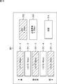
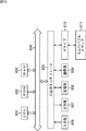
- FIG. 1 is a block diagram illustrating an embodiment of a video processing system to which the present technology is applied. It is a block diagram which shows the specific structural example of a video processing system. It is a flowchart for demonstrating a video switching process. It is a sequence diagram for demonstrating a video switching process. It is a figure which shows the example of the state of the video processing system before switching of video data. It is a figure which shows the example of the priority table before switching of video data. It is a flowchart for demonstrating the detail of a cutting
- FIG. 11 is a block diagram illustrating an example of a configuration of a computer.
- Embodiment 2 modes for carrying out the present technology (hereinafter referred to as embodiments) will be described. The description will be given in the following order. 1. Embodiment 2. FIG. Modified example
- FIG. 1 shows an embodiment of a video processing system to which the present technology is applied.
- the video processing system 101 is a system that is provided in, for example, a broadcasting station and performs various types of processing of video data, for example, generation, editing, transmission, transmission, and recording of video data.
- the video data includes not only video but also various data accompanying the video, for example, audio data, metadata, and the like.
- the video processing system 101 is configured to include video output devices 111-1 to 111-n, a network 112, a video switcher 113, a cable 114, and a video processing device 115.
- the video output devices 111-1 to 111-n and the video switcher 113 are connected to each other via a network 112.
- the video switcher 113 and the video processing device 115 are connected to each other via a cable 114.
- the video output devices 111-1 to 111-n are configured by various devices that output video data, such as cameras and archive systems.
- the video output devices 111-1 to 111-n have a communication function based on, for example, the Internet protocol (IP), and transmit video data to the video switcher 113 via the network 112.
- IP Internet protocol
- At least two video output devices 111-1 to 111-n are provided, and all of them are not necessarily the same type of device.
- the network 112 is configured by an IP network capable of communication based on IP, for example.
- the video switcher 113 is a device that performs switching of video data received from the video output devices 111-1 to 111-n, switching of video data transmitted to the video processing device 115, editing of received video data, and the like.
- the video switcher 113 is configured to include functions of a user interface unit 131, a control unit 132, a selection unit 133, a reception unit 134, an editing unit 135, and a transmission unit 136.
- the user interface unit 131 includes, for example, various input devices, display devices, and the like, and receives input of commands and data from the user, and controls display of the operation screen and the status of the video switcher 113.
- the user interface unit 131 supplies the input command and data to the control unit 132.
- a display device may be provided separately from the user interface unit 131 so that the user interface unit 113 controls display of an external display device.
- the control unit 132 controls the operation of each unit of the video switcher 113.
- the control unit 132 controls reception of video data from the video output devices 111-1 to 111-n and transmission of video data to the video processing device 115.
- the selection unit 133 dynamically sets the priority of each video data from the video output devices 111-1 to 111-n, and updates the priority table indicating the set priority.
- the selection unit 133 also selects the video output device 111 based on the set priority, the bandwidth used for each video data, the bandwidth of the network 112 that can be used by the video switcher 113 (hereinafter referred to as the maximum usable bandwidth), and the like.
- the video data received from -1 to 111-n is selected. Then, the selection unit 133 notifies the control unit 132 of the selection result of the received video data.
- the reception unit 134 selects video data received from the video output devices 111-1 to 111-n within the range of the maximum usable bandwidth of the network 112, and the selected video data is selected. Receive. The reception unit 134 supplies the received video data to the editing unit 135 and the transmission unit 136 as necessary.
- the reception unit 134 starting reception of video data is also referred to as connecting video data.
- the reception unit 134 stopping the reception of the video data is also referred to as cutting the video data.
- the editing unit 135 edits video data under the control of the control unit 132. For example, the editing unit 135 generates new video data by applying various effects to the video data (based on the video) or combining a plurality of video data (based on the video). The editing unit 135 supplies the edited video data to the transmission unit 136.
- the transmission unit 136 selects video data to be transmitted to the video processing device 115 from the video data supplied from the reception unit 134 or the editing unit 135 under the control of the control unit 132, and selects the selected video data.
- the image is transmitted to the video processing device 115 via the cable 114.
- a communication method such as SDI (Serial Digital Interface) is adopted.
- the video processing device 115 includes various devices that process video data.
- the video processing device 115 includes a transmission system that transmits video data, an archive system that stores video data, and the like.
- the video processing device 115 may include a plurality of devices, and may be configured by a system including a plurality of devices.
- sending video data means sending or outputting video data mainly for the purpose of broadcasting.
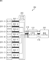
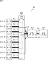
- FIG. 2 shows a configuration example of a video processing system 201 that is a more specific example of the video processing system 101 of FIG. In the figure, parts corresponding to those in FIG.
- the video processing system 201 includes cameras 211-1 to 211-8, cables 212-1 to 212-8, an Ethernet switch 213 (Ethernet is a registered trademark), a cable 214, a video switcher 113, a cable 114, and a transmission system 215. Configured to include.
- the cameras 211-1 to 211-8 are individually connected to the Ethernet switch 213 via cables 212-1 to 212-8.
- the Ethernet switch 213 is connected to the video switcher 113 via the cable 214.
- the network 112 in FIG. 1 is configured to include the cables 212-1 to 212-8, the Ethernet switch 213, and the cable 214.
- the video switcher 113 is connected to the transmission system 215 via the cable 114.
- the cameras 211-1 to 211-8 have a communication function based on, for example, the Internet protocol (IP), and the video data obtained by shooting is transferred to the Ethernet via the cables 212-1 to 212-8, respectively. Transmit to the switch 213.
- IP Internet protocol
- the Ethernet switch 213 transmits video data transmitted from the cameras 211-1 to 211-8 via the cables 212-1 to 212-8 to the video switcher 113 via the cable 214.
- the Ethernet switch 213 can switch video data to be transmitted to the video switcher 113 based on a request from the video switcher 113 or the like.
- the transmission system 215 includes, for example, various broadcasting devices that transmit video data, and transmits video data transmitted from the video switcher 113.
- the cameras 211-1 to 211-8 when it is not necessary to individually distinguish the cameras 211-1 to 211-8, they are simply referred to as cameras 211. Further, when there is no need to distinguish the cables 212-1 to 212-8, they are simply referred to as cables 212. Further, hereinafter, the video data of the cameras 211-1 to 211-8 will be referred to as video data 1 to 8, respectively.
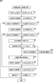
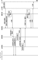
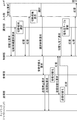
- Video Switching Process of Video Processing System 201 Next, the video switching process executed by the video processing system 201 will be described with reference to the flowchart of FIG. 3 and the sequence diagram of FIG.
- step S1 the video switcher 113 receives an input of a switching request. Specifically, when the user inputs a request for switching video data to be transmitted to the transmission system 215 via the user interface unit 131, the user interface unit 131 supplies the input switching request to the control unit 132. .
- the video processing system 201 in the state where the video processing system 201 is shown in FIG. 5, processing when the video data transmitted to the transmission system 215 is switched from the video data 1 of the camera 211-1 to the video data 6 of the camera 211-6 is performed. This will be described as a specific example as appropriate.
- the video switcher 113 In the state of FIG. 5, the video switcher 113 is receiving the video data 1 to 5, the video data 7 and the video data 8, and has not received the video data 6. In addition, the video switcher 113 transmits video data 1 of the video data being received to the transmission system 215.
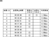
- FIG. 6 shows an example of a priority table held by the selection unit 133 when the video processing system 201 is shown in FIG.
- the priority table includes items of a video ID, a transmission stop time, a receiving flag, a transmitting flag, and a use band.
- the video ID is an ID for identifying the video data of each camera 211. That is, the video IDs 1 to 8 are assigned to the video data of the cameras 211-1 to 211-8, respectively.
- the transmission stop time indicates an elapsed time from when each video data is last transmitted from the video switcher 113 to the transmission system 215 until the present time (when the priority table is updated). In other words, the transmission stop time indicates an elapsed time from when the transmission of each video data from the video switcher 113 to the transmission system 215 is stopped until now.
- the transmission stop time of the video data 1 is set to 00:00:00.
- the transmission stop times of the video data 2 to 8 are 00:14:43, 00:05:01, 00:17:38, 00:08:22, 00:30:00, 00:04:33, respectively. , 00:02:15.
- the reception flag is a flag indicating whether or not each video data is being received by the video switcher 113. In this example, it is shown that video data 1 to 5, video data 7 and video data 8 are being received, and video data 6 is not being received.
- the transmission flag is a flag indicating whether the video switcher 113 is transmitting each video data to the transmission system 215 or not. In this example, it is indicated that the video data 1 is being transmitted and the video data 2 to 8 is not being transmitted.
- the bandwidth used indicates the bandwidth required to transmit each video data.
- the use bands of the video data 1 to 8 are 1.5 Gbps, 0.4 Gbps, 0.1 Gbps, 0.1 Gbps, 0.2 Gbps, 1.5 Gbps, 1.0 Gbps, and 1.5 Gbps, respectively.
- the upper limit (maximum usable bandwidth) of the bandwidth that can be used for data transmission from the Ethernet switch 213 to the video switcher 113 is 5.0 Gbps. That is, it is assumed that data having a maximum bandwidth of 5.0 Gbps can be transmitted from the Ethernet switch 213 to the video switcher 113.
- switching scheduled video data video data newly requested to be transmitted to the transmission system 215 in response to a switching request.
- the video data 6 is the video data to be switched.
- step S2 the control unit 132 confirms the video data being transmitted. That is, the control unit 132 confirms which video data of the video data 1 to 8 is being transmitted to the transmission system 215 by the transmission unit 136.
- step S3 the control unit 132 determines whether the switching scheduled video data is being transmitted. If it is determined that the switching scheduled video data is not being transmitted, the process proceeds to step S4.
- step S4 since the transmission unit 136 has not transmitted the video data 6 to the transmission system 215, it is determined that the switching-scheduled video data is not being transmitted, and the process proceeds to step S4.
- step S4 the control unit 132 confirms the video data being received. That is, the control unit 132 confirms which video data is being received by the receiving unit 134 among the video data 1 to 8.
- step S5 the control unit 132 determines whether the switching scheduled video data is being received. If it is determined that the switching-scheduled video data is not being received, the process proceeds to step S6.
- step S6 since the reception unit 134 has not received the video data 6, it is determined that the switching-scheduled video data is not being received, and the process proceeds to step S6.
- step S6 the control unit 132 confirms the free bandwidth. That is, the video switcher 113 confirms an available bandwidth that is a bandwidth that is not currently used for transmission of video data, among the maximum available bandwidth between the Ethernet switch 213 and the video switcher 113.
- the total bandwidth used for the video data 1 to 5, 7 and 8 being received is 4.80 Gbps.
- the free bandwidth is 0.20 Gbps.
- step S7 the control unit 132 determines whether or not the bandwidth is insufficient.
- the control unit 132 determines that the bandwidth is insufficient when the free bandwidth confirmed in step S6 is smaller than the usage bandwidth (hereinafter referred to as the requested bandwidth) of the scheduled switching video data that needs to be newly received. Determination is made, and the process proceeds to step S8.
- the required bandwidth (the bandwidth used for video data 6) is 1.50 Gbps, whereas the free bandwidth is 0.20 Gbps, so it is determined that the bandwidth is insufficient, and the processing is Proceed to step S8.
- step S8 the video switcher 113 executes a disconnection target selection process.
- the details of the cutting target selection process will be described with reference to the flowchart of FIG.
- step S31 the selection unit 133 calculates a necessary bandwidth. Specifically, the control unit 132 supplies a cutting target selection request signal to the selection unit 133.
- the disconnection target selection processing request signal includes, for example, information related to scheduled switching video data, video data being transmitted, video data being received, free bandwidth, and the like.
- the selection unit 133 obtains a value obtained by subtracting the free band from the use band of the switching scheduled video data as the necessary band. That is, the necessary bandwidth is a bandwidth that needs to be newly secured in order to receive the switching scheduled video data.
- step S32 the selection unit 133 performs a cutting candidate selection process.
- details of the cutting candidate selection process will be described with reference to the flowchart of FIG.
- the selection unit 133 sets the reception continuation priority. Specifically, the selection unit 133 compares the priority table with information included in the disconnection target selection request signal, and if there is a point that does not match, the selection unit 133 updates the priority table based on the information. Then, the selection unit 133 sets the reception continuation priority for the video data currently being received in the order from the shortest transmission stop time. Accordingly, the reception continuation priority of the video data currently being transmitted is set to the highest, and the reception continuation priority of the video data having the longest transmission stop time is set to the lowest. Note that the reception continuation priority is not set for video data that is not currently being received.
- reception continuation priority is an order indicating which video data is to be received with priority, and the cutting candidates are selected in order from video data having a lower reception continuation priority, as will be described later.
- step S52 the selection unit 133 selects the video data that has not been selected as the cutting candidate and has the lowest reception continuation priority as the cutting candidate.
- step S53 the selection unit 133 adds the use band of the selected video data to the cutting candidate band sum.
- the disconnection candidate bandwidth sum is the sum of the use bandwidths of the video data selected as the disconnection candidates, and the bandwidth that is newly secured when the reception of the video data selected as the disconnection candidates is stopped It is.
- step S54 the selection unit 133 determines whether or not the cutting candidate band sum is equal to or greater than the necessary band. When it is determined that the total cutting candidate band is less than the necessary band, the process returns to step S52.
- step S54 the processes in steps S52 to S54 are repeatedly executed until it is determined that the total cutting candidate band is greater than or equal to the necessary band.
- step S54 if it is determined in step S54 that the total cutting candidate band is greater than or equal to the necessary band, the cutting candidate selection process ends.
- the cutting candidates are selected in order from the video data having the lowest reception continuation priority until the sum of the cutting candidate bands exceeds the necessary band.
- the cutting candidates are selected in order from the video data having the lowest reception continuation priority until the sum of the usable bandwidth and the free bandwidth of the cutting candidates becomes equal to or greater than the required bandwidth.
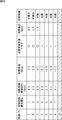
- FIG. 9 is a table showing an example of setting the reception continuation priority in the specific example described above.
- the table in FIG. 9 includes items of a video ID, a transmission flag, a reception flag, a reception request flag, a transmission stop time, a reception video band, a request band, and a reception continuation priority.
- the video ID, transmission flag, reception flag, and transmission stop time are the same as those in the priority table of FIG.
- the reception request flag is a flag indicating which video data is requested to be received, and the value for the switching scheduled video data that needs to be newly received is set to ON. In this example, it is shown that reception of the video data 6 is requested.
- the receiving video bandwidth indicates the usage bandwidth of the video data being received.
- the use band values of video data other than the video data 6 not currently received are shown.
- the requested bandwidth is set to the sum of the used bandwidths of the video data for which the reception request flag is set to ON, that is, the sum of the used bandwidths of the video data to be switched that need to be newly received.
- the use band value of the video data 6 in which the reception request flag is set to ON is shown.
- the reception continuation priority order is from video data 1, video data 8, video data 7, video data 3, video data 5, video data to those with a short transmission stop time except for video data 6 that is not currently received. 2 and video data 4 are set in this order.
- FIG. 10 is a table showing cutting candidate selection results in the specific example described above.
- the table of FIG. 10 includes items of video ID, reception continuation priority, disconnection candidate band sum, surplus band, necessary band arrival flag, boundary detection, and disconnection candidate.
- the video ID is the same as that in the priority table in FIG. 6, and the reception continuation priority is the same as that in the table in FIG.
- the disconnection candidate band sum indicates a value obtained by integrating the use bands in order from video data having a lower reception continuation priority.
- the total cut candidate band for the row of the video data 4 indicates the use band of the video data 4
- the total cut candidate band for the row of the video data 2 indicates the integrated value of the use bands of the video data 4 and the video data 2.
- the cutting candidate band sum of the row of the video data 5 indicates the integrated value of the usage bands of the video data 4, the video data 2, and the video data 5.
- the surplus bandwidth indicates a value obtained by subtracting the necessary bandwidth from the total cutting candidate bandwidth.
- the surplus bandwidth value is negative, it means that the bandwidth is insufficient by that value, and when the surplus bandwidth value is positive, it means that the bandwidth is surplus by that value.
- the necessary band arrival flag is a flag indicating whether or not the sum of the candidate cutting bands has reached the necessary band. If the surplus band value is less than 0, the necessary band arrival flag is set to off and the surplus band value is 0 or more. If set to ON.
- Boundary detection indicates the cutting candidate band sum when the cutting candidate band sum exceeds the required band.
- the cutting candidate indicates whether each video data is a cutting candidate.
- the video data 4 having the lowest cutting candidate exclusion priority (seventh) is selected as a cutting candidate.
- the disconnection candidate band sum is 0.1 Gbps, and the surplus band is -1.2 Gbps.
- the video data 2 with the cutting candidate exclusion priority of 6th is selected as the cutting candidate.
- the total disconnection candidate bandwidth is 0.5 Gbps, and the surplus bandwidth is -0.8 Gbps.
- the video data 5 with the disconnection candidate exclusion priority of 5th is selected as the disconnection candidate.
- the total disconnection candidate bandwidth is 0.7 Gbps, and the surplus bandwidth is -0.6 Gbps.
- the video data 3 having the fourth disconnection candidate exclusion priority is selected as the disconnection candidate.
- the sum of the candidate cutting bandwidths is 0.8 Gbps, and the surplus bandwidth is -0.5 Gbps.
- the video data 7 having the third highest disconnection candidate exclusion priority is selected as a disconnection candidate.
- the total disconnection candidate bandwidth is 1.8 Gbps, and the surplus bandwidth is 0.5 Gbps.
- the selection of the cutting candidate is completed.
- video data 2 to 5 and 7 are finally selected as cutting candidates, and video data 1 and 8 are excluded from cutting candidates.
- step S ⁇ b> 33 the selection unit 133 executes a cutting target determination process.
- the details of the cutting target determination process will be described with reference to the flowchart of FIG.
- step S71 the selection unit 133 sets the cutting candidate exclusion priority. Specifically, the selection unit 133 sets the disconnection candidate exclusion priority for the selected disconnection candidates in descending order of the original reception continuation priority.
- the disconnection candidate exclusion priority order is an order indicating which video data is preferentially excluded from the selected disconnection candidates. As will be described later, in order from video data having a higher disconnection candidate exclusion priority order. It is considered whether to exclude from cutting candidates.
- step S72 the selection unit 133 selects video data having the highest cutting candidate exclusion priority from unprocessed cutting candidates.
- an unprocessed cutting candidate is video data that has not yet been a target of cutting target determination processing among cutting candidates.
- step S73 the selection unit 133 subtracts the use band of the selected video data from the cutting candidate band sum.
- step S74 the selection unit 133 determines whether or not the cutting candidate band sum is equal to or greater than the necessary band. If it is determined that the total cutting candidate band is greater than or equal to the necessary band, that is, if the necessary band can be secured even if the selected video data is excluded from the cutting candidates, the process proceeds to step S75.
- step S75 the selection unit 133 excludes the selected video data from the cutting candidates.
- step S74 determines whether the total cutting candidate band is less than the necessary band, that is, if the selected video data is excluded from the cutting candidates.
- step S76 the selection unit 133 adds the use band of the selected video data to the cutting candidate band sum. Thereby, the cutting candidate band sum returns to the value before being subtracted in the process of step S72.
- step S77 the selection unit 133 determines whether or not the cutting candidate band sum is equal to the necessary band. If it is determined that the cutting candidate band sum is not equal to the necessary band, the process proceeds to step S78. This is a case where the sum of the disconnection candidate bands is larger than the necessary band, and there is still room for reducing the disconnection candidates.
- step S78 the selection unit 133 determines whether all cutting candidates have been processed. If it is determined that all the cutting candidates have not been processed yet, the processing returns to step S72.
- steps S72 to S78 are repeatedly executed until it is determined in step S77 that the total sum of the cutting candidate bands is equal to the necessary band or until it is determined in step S78 that all cutting candidates have been processed.
- step S78 if it is determined in step S78 that all cutting candidates have been processed, the cutting target determination process ends.
- step S77 If it is determined in step S77 that the total cutting candidate band is equal to the necessary band, the cutting target determination process ends because there is no more room for cutting cutting candidates.
- the table of FIG. 12 includes items of video ID, disconnection candidate exclusion priority, surplus bandwidth, disconnection candidate exclusion availability, disconnection candidate exclusion bandwidth sum, disconnection target bandwidth sum, and final determination.
- the video ID is the same as the priority table of FIG.
- the disconnection candidate exclusion priority order is the video data 7, the video data 3, the video data 5, the video data 2,
- the video data 4 is set in this order.
- the surplus bandwidth indicates a value obtained by subtracting the necessary bandwidth from the total cutting candidate bandwidth.
- the value of the surplus band is negative, it means that the band is insufficient by that value, and when the value of the surplus band is positive, it means that the band is surplus by that value.
- the disconnection candidate exclusion availability indicates whether or not the target video data can be excluded from the disconnection candidates.
- Cutting candidate exclusion band sum indicates the sum of the use band of video data excluded from cutting candidates.
- the disconnection target band total indicates the total use band of video data (disconnection target) that is not excluded from the disconnection candidates.
- the final judgment indicates the final judgment result as to whether or not to cut the target video data.
- the video data indicated as “disconnected” is the video data that is determined to be disconnected and stops receiving.
- the video data indicated as “continue reception” is excluded from candidates for disconnection and continues to be received. Video data.
- the video data 3 having the second highest disconnection candidate exclusion priority is excluded from the disconnection candidates.
- the sum of the disconnection candidate bands is 1.7 Gbps and the necessary band is 1.3 Gbps
- the surplus band is 0.4 Gbps and the necessary band can be secured. Therefore, the video data 3 is excluded from the cutting candidates.
- the disconnection candidate excluded band sum is 0.1 Gbps, and the disconnection target band sum remains 1.0 Gbps.
- the video data 5 with the disconnection candidate exclusion priority of 3rd is excluded from the disconnection candidates.
- the sum of the disconnection candidate bands is 1.5 Gbps and the necessary band is 1.3 Gbps
- the surplus band is 0.2 Gbps and the necessary band can be secured. Therefore, the video data 5 is excluded from the cutting candidates.
- the disconnection candidate excluded band sum is 0.3 Gbps, and the disconnection target band sum remains 1.0 Gbps.
- the disconnection candidate bands is 1.4 Gbps and the necessary band is 1.3 Gbps, so the surplus band is 0.1 Gbps and the necessary band can be secured. Therefore, the video data 4 is excluded from the cutting candidates. Then, the disconnection candidate excluded band sum is 0.4 Gbps, and the disconnection target band sum remains 1.4 Gbps.
- priority can be given to continuous reception of video data having a high priority (reception continuation priority), and the target to be disconnected can be minimized.
- the video data having the highest priority for cutting candidate exclusion among cutting candidates (hereinafter referred to as the final cutting candidate) is the video data that was last selected as the cutting candidate in the cutting candidate selection process of FIG. That is, when the final cutting candidate is added to the cutting candidates, the cutting candidate band sum is not less than the necessary band for the first time. Therefore, if the final cutting candidates are excluded from the cutting candidates, the total cutting candidate band is surely less than the necessary band. Therefore, the final cutting candidates are excluded from the objects to be considered for exclusion from the cutting candidates and automatically determined as cutting targets. You may make it do. Similarly, a cutting candidate whose usage band is equal to or higher than the final cutting candidate may be excluded from the objects to be excluded from the cutting candidates and automatically determined as a cutting object. Thereby, the amount of calculation can be reduced and the processing speed can be increased.
- step S9 the video switcher 113 switches the received video data.
- the selection unit 133 supplies a response signal to the cutting target selection request signal to the control unit 132.
- This response signal includes, for example, switching scheduled video data and information indicating a cutting target.
- the control unit 132 supplies a reception switching request signal to the reception unit 134.
- the reception switching request signal includes, for example, switching scheduled video data and information indicating a cutting target.
- the receiving unit 134 transmits a transmission stop request signal for requesting stop of transmission of the video data selected as the disconnection target to the Ethernet switch 213 via the cable 214.
- the Ethernet switch 213 that has received the transmission stop request signal stops the transmission of the video data selected as the disconnection target. As a result, reception of the video data to be disconnected by the receiving unit 134 of the video switcher 113 is stopped, and the free bandwidth is expanded.
- reception unit 134 transmits a transmission start request signal for requesting the start of transmission of the switching scheduled video data to the Ethernet switch 213 via the cable 214.
- Ethernet switch 213 starts transmission of the scheduled video data.
- the receiving unit 134 of the video switcher 113 starts receiving the scheduled switching video data.
- the reception unit 134 supplies a response signal to the reception switching request signal to the control unit 132.
- step S6 determines whether the bandwidth is not insufficient. If the free bandwidth confirmed in step S6 is equal to or greater than the requested bandwidth in step S7, it is determined that the bandwidth is not insufficient, and the process proceeds to step S10.
- step S10 the video switcher 113 starts receiving the switching scheduled video data.
- the selection unit 133 supplies a response signal to the cutting target selection request signal to the control unit 132.
- This response signal includes, for example, information indicating the switching scheduled video data.
- the control unit 132 supplies a reception switching request signal to the reception unit 134.
- the reception switching request signal includes, for example, information indicating switching scheduled video data.
- the receiving unit 134 transmits a transmission start request signal for requesting the start of transmission of the switching scheduled video data to the Ethernet switch 213 via the cable 214.
- Ethernet switch 213 starts transmission of the scheduled video data.
- the receiving unit 134 of the video switcher 113 starts receiving the scheduled switching video data.
- the reception unit 134 supplies a response signal to the reception switching request signal to the control unit 132.
- step S5 if it is determined in step S5 that the switching-scheduled video data is being received, the processes in steps S6 to S10 are skipped and the process proceeds to step S11.
- step S11 the video switcher 113 switches the video data to be transmitted.
- the control unit 132 supplies a transmission switching request signal to the transmission unit 136.
- the transmission switching request signal includes, for example, information indicating switching scheduled video data.
- the transmission unit 136 switches the video data to be transmitted to the transmission system 215 via the cable 114 from the currently transmitted video data to the scheduled switching video data. Then, the transmission unit 136 supplies a response signal to the transmission switching request signal to the control unit 132.
- the state of the video processing system 201 changes from the state shown in FIG. 5 to the state shown in FIG. That is, transmission of the video data 2 and the video data 7 from the Ethernet switch 213 to the video switcher 113 is stopped, and transmission of the video data 6 is started. In addition, the transmission of the video data 1 from the video switcher 113 to the transmission system 215 is stopped, and the transmission of the video data 6 is started.
- step S12 the video switcher 113 updates the priority table. Specifically, the control unit 132 supplies a switching completion notification signal to the selection unit 133.
- the switching completion notification signal includes, for example, a video data transmission / reception switching result.
- the selection unit 133 updates the priority table.
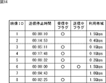
- FIG. 14 shows an example after the priority table is updated after the video processing system 201 changes to the state shown in FIG.
- the transmission stop time and the reception of each video data are switched according to the switching of the transmission / reception of the video data and the passage of time.
- the values of the medium flag and the transmission flag are updated.
- the selection unit 133 supplies a response signal to the switching completion notification signal to the control unit 132 after updating the priority table.
- the control unit 132 supplies a response signal for the switching request signal to the user interface unit 131.
- the user interface unit 131 returns a response to the switching request to the user by a method such as presenting a response screen or sounding a sound effect.
- step S3 if it is determined in step S3 that the switching-scheduled video data is being transmitted, the processes in steps S4 to S12 are skipped, and the video switching process is terminated.
- the video data received by the video switcher 113 is selected so as not to exceed the maximum usable bandwidth of the network. This prevents video data loss and image quality degradation.
- video data priority (reception continuation priority) is dynamically set based on the transmission stop time, and when bandwidth is insufficient, video data to stop receiving is selected based on that priority Is done. Further, after selecting a cutting candidate, video data to be excluded from cutting candidates is selected based on the priority of the video data (cutting candidate exclusion priority) so that the cutting target is minimized.
- video data can be efficiently transmitted from the cameras 211-1 to 211-8 to the video switcher 113 within the range of the maximum usable bandwidth of the network.
- the video switcher 113 can receive video data with higher priority, that is, video data with a higher probability of transmission to the transmission system 215 as much as possible.
- the video switcher 113 switches the video data to be transmitted to the transmission system 215, there is a high probability that the video data to be newly transmitted has already been received, speeding up the processing, or switching the video data to be received. The number of times can be reduced.
- FIG. 15 shows a sequence diagram of video switching processing executed by the video processing system 201 when the user selects a selection target.
- the user interface unit 131 of the video switcher 113 supplies a switching request signal to the control unit 132 when a switching request is input from the user.
- the control unit 132 supplies a cutting candidate selection request signal to the selection unit 133.
- the selection unit 133 selects a cutting candidate by the above-described processing, and supplies a response signal to the cutting candidate selection request signal to the control unit 132.
- the cutting candidate selection request signal includes, for example, a cutting candidate selection result.
- the control unit 132 supplies a response signal to the switching request to the user interface unit 131.
- This response signal includes, for example, a selection result of the cutting candidate.
- the user interface unit 131 displays, for example, a cutting target selection screen 301 shown in FIG.
- selection buttons 311-1 to 311-5 for accepting selection of cutting candidates are displayed.
- the selection buttons 311-1 to 311-5 correspond to different cutting candidates.
- the selection buttons 311-1 to 311-5 are the video data 7, video data 3, and video data, which are cutting candidates, respectively. 5 corresponds to video data 2 and video data 4.
- the selection buttons 311-1 to 311-5 display the video ID and the use band of the corresponding video data.
- the video data corresponding to the selection buttons 311-1 to 311-5 are arranged from the top in descending order of priority (reception continuation priority).
- the selection candidate is presented to the user together with the priority.
- the user can select a cutting target from among cutting candidates or cancel the selection by designating the selection buttons 311-1 to 311-5. Further, the selection buttons 311-1 to 311-5 are displayed so that a button corresponding to the video data selected as a cutting target can be distinguished from a button that is not. In this example, video data corresponding to the selection button 311-1, the selection button 311-3, and the selection button 311-5 is selected as a cutting target, and the video corresponding to the selection button 311-2 and the selection button 311-4 is selected. Data is not selected for disconnection.
- a window 312 and a window 313 and a switching button are displayed.
- the window 312 displays the total bandwidth used for the video data currently selected for disconnection.
- the necessary bandwidth is displayed.
- the switch button 314 is operated when the cutting target is confirmed and the transmission / reception of video data is switched.
- the user can select video data to be excluded from the cutting candidates and can select desired video data as a cutting target within a range in which the necessary bandwidth can be easily secured.
- the user interface unit 131 supplies a selection result notification signal indicating the selection result of the disconnection target to the control unit 132.
- the cutting target determination process in step S33 of FIG. 7 may be omitted. In other words, reception may be stopped without reducing the selected cutting candidates.
- a part of the function of the video switcher may be made independent and provided in a server or the like separate from the video switcher.
- the video processing system 401 in FIG. 17 includes cameras 211-1 to 211-8, cables 212-1 to 212-8, an Ethernet switch 213, cables 411-1 and 411-2, and a video switcher 412-1. , 412-2, cables 413-1 and 413-2, a transmission system 414, an archive system 415, a cable 416, and a bandwidth management server 417.
- the cameras 211-1 to 211-8 are individually connected to the Ethernet switch 213 via cables 212-1 to 212-8.
- the Ethernet switch 213 is connected to the video switcher 412-1 via the cable 411-1, connected to the video switcher 412-2 via the cable 411-2, and connected to the bandwidth management server 417 via the cable 416.
- the network 112 in FIG. 1 is configured to include the cables 212-1 to 212-8, the Ethernet switch 213, the cables 411-1 and 411-2, and the cable 416.
- the video switcher 412-1 is connected to the transmission system 414 via the cable 413-1.
- the video switcher 412-2 is connected to the transmission system 414 via the cable 413-2.
- the video switchers 412-1 and 412-2 have a configuration in which, for example, the selection unit 133 is removed from the video switcher 113 of FIG.
- the bandwidth management server 417 is configured to include a communication unit 431 and a selection unit 432.
- the communication unit 431 communicates with the Ethernet switch 213 via the cable 416.
- the selection unit 432 has substantially the same function as the selection unit 133 of the video switcher 113 in FIG. That is, the selection unit 432 dynamically sets the priority of the video data from the cameras 211-1 to 211-8 for each video switcher based on the information supplied from the video switchers 412-1 and 412-2. Then, the priority table indicating the set priority is updated. In addition, the selection unit 432 selects video data that each video switcher receives from the cameras 211-1 to 211-8 based on the set priority, the usage bandwidth of each video data, the maximum available bandwidth, and the like. Then, the selection unit 432 sends the selection result of the received video data to the video switcher 412-1 or the video switcher 412- via the communication unit 431, the cable 416, the Ethernet switch 213, the cable 411-1 or the cable 411-2. 2 to send.
- the video switcher 412-1 and the video switcher 412-2 perform switching of received video data based on the selection result supplied from the bandwidth management server 417.
- the bandwidth management server 417 can be provided with a function for mediating processing between video switchers, and a plurality of video switchers can be operated in a coordinated manner.
- the network configuration and communication method to which the present technology can be applied are not limited to the above-described examples, and other configurations and communication methods can be adopted.
- a communication method based on a protocol other than IP can be employed.
- the present invention can be applied to a network having a configuration in which Ethernet switches are connected in two or more stages in series.
- an example in which communication between each device is performed by wire is shown, but it is also possible to change to wireless communication.
- Modification 3 Modification related to transmission target
- the video switching process has been described by taking as an example the case where one video data is transmitted from the video switcher 113 to the transmission system 215.
- the video data to be transmitted and received can be switched by the same processing.
- the above-described processing can secure the band of the video data that needs to be newly received.
- video data for which reception is to be stopped may be selected based on priority.
- the case of transmitting two or more video data includes not only the case of transmitting two or more video data individually but also the case of transmitting two or more video data by combining them.
- the present technology can be applied when transmitting contents other than video data such as audio data. Further, the present technology can also be applied when transmitting a plurality of types of content.
- the series of processes described above can be executed by hardware or can be executed by software.
- a program constituting the software is installed in the computer.
- the computer includes, for example, a general-purpose personal computer capable of executing various functions by installing various programs by installing a computer incorporated in dedicated hardware.
- FIG. 18 is a block diagram showing an example of the hardware configuration of a computer that executes the above-described series of processing by a program.
- a CPU Central Processing Unit
- ROM Read Only Memory
- RAM Random Access Memory
- An input / output interface 605 is further connected to the bus 604.
- An input unit 606, an output unit 607, a storage unit 608, a communication unit 609, and a drive 610 are connected to the input / output interface 605.
- the input unit 606 includes a keyboard, a mouse, a microphone, and the like.
- the output unit 607 includes a display, a speaker, and the like.
- the storage unit 608 includes a hard disk, a nonvolatile memory, and the like.
- the communication unit 609 includes a network interface or the like.
- the drive 610 drives a removable medium 611 such as a magnetic disk, an optical disk, a magneto-optical disk, or a semiconductor memory.
- the CPU 601 loads the program stored in the storage unit 608 to the RAM 603 via the input / output interface 605 and the bus 604 and executes the program, for example. Is performed.
- the program executed by the computer (CPU 601) can be provided by being recorded on a removable medium 611 as a package medium, for example.
- the program can be provided via a wired or wireless transmission medium such as a local area network, the Internet, or digital satellite broadcasting.
- the program can be installed in the storage unit 608 via the input / output interface 605 by attaching the removable medium 611 to the drive 610. Further, the program can be received by the communication unit 609 via a wired or wireless transmission medium and installed in the storage unit 608. In addition, the program can be installed in the ROM 602 or the storage unit 608 in advance.
- the program executed by the computer may be a program that is processed in time series in the order described in this specification, or in parallel or at a necessary timing such as when a call is made. It may be a program for processing.
- the system means a set of a plurality of components (devices, modules (parts), etc.), and it does not matter whether all the components are in the same housing. Accordingly, a plurality of devices housed in separate housings and connected via a network and a single device housing a plurality of modules in one housing are all systems. .
- the present technology can take a cloud computing configuration in which one function is shared by a plurality of devices via a network and is jointly processed.
- each step described in the above flowchart can be executed by one device or can be shared by a plurality of devices.
- the plurality of processes included in the one step can be executed by being shared by a plurality of apparatuses in addition to being executed by one apparatus.
- the present technology can take the following configurations.
- a receiving unit that receives video data from a plurality of first devices within a predetermined bandwidth via a network; A transmission unit that selects one or more of the received video data and transmits it to a second device that transmits the video data; A selection unit that dynamically sets the priority of each video data and selects video data received from the plurality of first devices based on the priority; A transmission / reception control unit for controlling transmission and reception of video data, When the bandwidth necessary for receiving new video data is insufficient, the selection unit selects video data to be stopped from reception of video data based on the priority, The transmission / reception control unit controls to stop receiving the selected video data and start receiving the new video data.
- the video switching device sets the priority of each video data based on an elapsed time after stopping transmission to the second device.
- the selection unit sets the highest priority of video data being transmitted to the second device.
- the selection unit has a low priority among the video data being received until the sum of the use bandwidth of the candidate video data to be stopped and the current available bandwidth is equal to or greater than the use bandwidth of the new video data.
- the video transmission / reception apparatus After selecting the candidates in order, select video data to be excluded from the candidates in a range in which the sum of the use bandwidth of the candidates and the current free bandwidth is not less than or equal to the use bandwidth of the new video data,
- the video transmission / reception apparatus according to any one of (1) to (3), wherein the transmission / reception control unit controls to stop reception of video data remaining in the candidate finally.
- the selection unit selects the candidates of video data to be received from the video data being received from the lowest priority until the sum of the current video bandwidth and the current available bandwidth becomes equal to or greater than the new video data usage bandwidth.
- Select A user interface unit that controls to present the selected candidate together with the priority, and that accepts a selection for the presented candidate;
- the video transmission / reception apparatus according to any one of (1) to (3), wherein the transmission / reception control unit performs control so as to stop reception of video data selected from the candidates.
- Video data is received from a plurality of first devices within a predetermined bandwidth via a network, one or more of the received video data is selected, and transmitted to a second device that transmits the video data
- the video switching device to Set the priority of each video data dynamically, If the bandwidth required for receiving new video data is insufficient, based on the priority, select video data to stop receiving from the video data being received,
- a video switching method including a step of stopping reception of selected video data and starting reception of the new video data.
- Video data is received from a plurality of first devices within a predetermined bandwidth via a network, one or more of the received video data is selected, and transmitted to a second device that transmits the video data
- a second device that transmits the video data
- the video switching device computer that Set the priority of each video data dynamically, If the bandwidth required for receiving new video data is insufficient, based on the priority, select video data to stop receiving from the video data being received,
- a program for executing a process including a step of controlling to stop receiving selected video data and start receiving the new video data.
- Video data is received from a plurality of first devices within a predetermined bandwidth via a network, one or more of the received video data is selected, and transmitted to a second device that transmits the video data
- the video switching device dynamically sets the priority of each video data being received, and when the bandwidth necessary for receiving new video data is insufficient, the video switching device is based on the priority.
- An information processing apparatus comprising: a communication unit that notifies the video switching apparatus of selected video data.
- 101 video processing system 111 video output device, 112 network, 113 video switcher, 114 cable, 115 video processing device, 131 user interface unit, 132 control unit, 133 selection unit, 134 reception unit, 135 editing unit, 136 transmission unit, 201 video processing system, 211-1 to 211-8 camera, 212-1 to 212-8 cable, 213 Ethernet switch, 214 cable, 215 sending system, 401 video processing system, 411-1 and 411-2 cable, 412 1,412-2 video switcher, 413-1, 413-2 cable, 414 sending system, 415 archive system, 416 cable, 417 bandwidth management server, 431 Shin part, 432 the selection unit
Landscapes
- Engineering & Computer Science (AREA)
- Signal Processing (AREA)
- Multimedia (AREA)
- Databases & Information Systems (AREA)
- Physics & Mathematics (AREA)
- Astronomy & Astrophysics (AREA)
- General Physics & Mathematics (AREA)
- Business, Economics & Management (AREA)
- General Business, Economics & Management (AREA)
- Two-Way Televisions, Distribution Of Moving Picture Or The Like (AREA)
- Data Exchanges In Wide-Area Networks (AREA)
Abstract
本技術は、ネットワークの利用可能な帯域幅の範囲内で、データの欠損や画質の劣化を防止しつつ、効率よく映像データを伝送することができるようにする映像切替え装置、映像切替え方法、プログラム、及び、情報処理装置に関する。 ビデオスイッチャは、複数の映像出力装置からネットワークを介して所定の帯域幅の範囲内で映像データを受信する受信部と、受信した映像データの中から1以上を選択し、映像処理装置に送信する送信部と、各映像データの優先度を動的に設定し、受信する映像データを選択する選択部と、映像データの送受信を制御する制御部とを備える。選択部は、新たな映像データの受信に必要な帯域幅が不足している場合、優先度に基づいて受信中の映像データの中から受信を停止する映像データを選択し、制御部は選択された映像データの受信を停止し、新たな映像データの受信を開始するように制御する。本技術は、例えばビデオスイッチャに適用できる。
Description
本技術は、映像切替え装置、映像切替え方法、プログラム、及び、情報処理装置に関し、特に、ネットワークを介して複数の映像データを受信し、受信した複数の映像データの中から後段に送信する映像データを切り替える場合に用いて好適な映像切替え装置、映像切替え方法、プログラム、及び、情報処理装置に関する。
放送局等で放送用の映像データをベストエフォート型の通信ネットワークを利用して伝送する場合、データの欠損や画質の変化が許されないため、ネットワークのトラフィックに応じて、映像データのエンコードレートを動的に変化させる方法を採用することはできない。従って、伝送する映像データの利用帯域がネットワークの帯域幅を超えないように、映像データの伝送量を制御する必要がある。
その対策の一例として、従来、複数のクライアントが接続されているLANの帯域幅が不足する場合、クライアントの優先順位、コンテンツの優先度、コンテンツの使用帯域、コンテンツの使用時間に基づく予め設定された調停条件によりクライアント間で調停を行い、受信するコンテンツを選択することが提案されている(例えば、特許文献1参照)。
しかしながら、特許文献1に記載の発明では、調停に用いるコンテンツの優先度等のパラメータが事前に登録された静的なものであり、例えば、映像データの優先度が動的に変化する場合に対応できない。
そこで、本技術は、ネットワークの利用可能な帯域幅の範囲内で、データの欠損や画質の劣化を防止しつつ、効率よく映像データを伝送できるようにするものである。
本技術の第1の側面の映像切替え装置は、複数の第1の装置からネットワークを介して所定の帯域幅の範囲内で映像データを受信する受信部と、受信した映像データの中から1以上を選択し、映像データの送出を行う第2の装置に送信する送信部と、各映像データの優先度を動的に設定し、前記優先度に基づいて、前記複数の第1の装置から受信する映像データを選択する選択部と、映像データの送信及び受信を制御する送受信制御部とを備え、前記選択部は、新たな映像データの受信に必要な帯域幅が不足している場合、前記優先度に基づいて、受信中の映像データの中から受信を停止する映像データを選択し、前記送受信制御部は、選択された映像データの受信を停止し、前記新たな映像データの受信を開始するように制御する。
前記選択部には、前記第2の装置への送信を停止してからの経過時間に基づいて、各映像データの前記優先度を設定させることができる。
前記選択部には、前記第2の装置に送信中の映像データの優先度を最も高く設定させることができる。
前記選択部には、受信を停止する映像データの候補の利用帯域と現在の空き帯域の総和が前記新たな映像データの利用帯域以上になるまで、受信中の映像データの中から前記優先度の低い順に前記候補を選択した後、前記候補の利用帯域と現在の空き帯域の総和が前記新たな映像データの利用帯域以下にならない範囲で前記候補から除外する映像データを選択させ、前記送受信制御部には、最終的に前記候補に残った映像データの受信を停止するように制御させることができる。
前記選択部には、受信を停止する映像データの候補と現在の空き帯域の総和が前記新たな映像データの利用帯域以上になるまで、受信中の映像データの中から前記優先度の低い順に前記候補を選択させ、選択された前記候補を前記優先度とともに提示するように制御し、提示した前記候補に対する選択を受け付けるユーザインタフェース部をさらに設け、前記送受信制御部には、前記候補の中から選択された映像データの受信を停止するように制御させることができる。
本技術の第1の側面の映像切替え方法は、複数の第1の装置からネットワークを介して所定の帯域幅の範囲内で映像データを受信し、受信した映像データの中から1以上を選択し、映像データの送出を行う第2の装置に送信する映像切替え装置が、各映像データの優先度を動的に設定し、新たな映像データの受信に必要な帯域幅が不足している場合、前記優先度に基づいて、受信中の映像データの中から受信を停止する映像データを選択し、選択された映像データの受信を停止し、前記新たな映像データの受信を開始するように制御するステップを含む。
本技術の第1の側面のプログラムは、複数の第1の装置からネットワークを介して所定の帯域幅の範囲内で映像データを受信し、受信した映像データの中から1以上を選択し、映像データの送出を行う第2の装置に送信する映像切替え装置のコンピュータに、各映像データの優先度を動的に設定し、新たな映像データの受信に必要な帯域幅が不足している場合、前記優先度に基づいて、受信中の映像データの中から受信を停止する映像データを選択し、選択された映像データの受信を停止し、前記新たな映像データの受信を開始するように制御するステップを含む処理を実行させる。
本技術の第2の側面の情報処理装置は、複数の第1の装置からネットワークを介して所定の帯域幅の範囲内で映像データを受信し、受信した映像データの中から1以上を選択し、映像データの送出を行う第2の装置に送信する映像切替え装置が受信中の各映像データの優先度を動的に設定し、新たな映像データの受信に必要な帯域幅が不足している場合、前記優先度に基づいて、前記映像切替え装置が受信中の映像データの中から受信を停止する映像データを選択する選択部と、選択された映像データを前記映像切替え装置に通知する通信部とを備える。
本技術の第1の側面においては、各映像データの優先度が設定され、新たな映像データの受信に必要な帯域幅が不足している場合、前記優先度に基づいて、受信中の映像データの中から受信を停止する映像データが選択され、選択された映像データの受信が停止され、前記新たな映像データの受信が開始される。
本技術の第2の側面においては、複数の第1の装置からネットワークを介して所定の帯域幅の範囲内で映像データを受信し、受信した映像データの中から1以上を選択し、映像データの送出を行う第2の装置に送信する映像切替え装置が受信中の各映像データの優先度が設定され、新たな映像データの受信に必要な帯域幅が不足している場合、前記優先度に基づいて、前記映像切替え装置が受信中の映像データの中から受信を停止する映像データが選択され、選択された映像データが前記映像切替え装置に通知される。
本技術の第1の側面又は第2の側面によれば、ネットワークの利用可能な帯域幅の範囲内で、データの欠損や画質の劣化を防止しつつ、効率よく映像データを伝送することができる。
以下、本技術を実施するための形態(以下、実施の形態という)について説明する。なお、説明は以下の順序で行う。
1.実施の形態
2.変形例
1.実施の形態
2.変形例
<1.実施の形態>
[映像処理システムの構成例]
図1は、本技術を適用した映像処理システムの一実施の形態を示している。
[映像処理システムの構成例]
図1は、本技術を適用した映像処理システムの一実施の形態を示している。
映像処理システム101は、例えば放送局等に設けられ、映像データの各種の処理、例えば、映像データの生成、編集、伝送、送出、記録等を行うシステムである。
ここで、映像データには、映像だけでなく、映像に付随する各種のデータ、例えば、音声データ、メタデータ等が含まれる。
映像処理システム101は、映像出力装置111-1乃至111-n、ネットワーク112、ビデオスイッチャ113、ケーブル114、及び、映像処理装置115を含むように構成される。映像出力装置111-1乃至111-nとビデオスイッチャ113とは、ネットワーク112を介して相互に接続されている。ビデオスイッチャ113と映像処理装置115とは、ケーブル114を介して相互に接続されている。
映像出力装置111-1乃至111-nは、例えば、カメラ、アーカイブシステム等の映像データの出力を行う各種の装置により構成される。また、映像出力装置111-1乃至111-nは、例えば、インターネットプロトコル(IP)に基づく通信機能を有しており、ネットワーク112を介してビデオスイッチャ113に映像データを送信する。
なお、映像出力装置111-1乃至111-nは、少なくとも2つ以上設けられ、必ずしも全てが同じ種類の装置である必要はない。
ネットワーク112は、例えば、IPに基づく通信が可能なIPネットワークにより構成される。
ビデオスイッチャ113は、映像出力装置111-1乃至111-nから受信する映像データの切替え、映像処理装置115に送信する映像データの切替え、受信した映像データの編集等を行う装置である。ビデオスイッチャ113は、ユーザインタフェース部131、制御部132、選択部133、受信部134、編集部135、及び、送信部136の機能を含むように構成される。
ユーザインタフェース部131は、例えば、各種の入力デバイス、表示デバイス等により構成され、ユーザからの指令やデータ等の入力を受け付けたり、操作画面やビデオスイッチャ113の状態等の表示を制御したりする。ユーザインタフェース部131は、入力された指令やデータ等を制御部132に供給する。なお、例えば、ユーザインタフェース部131とは別に表示デバイスを設け、ユーザインタフェース部113が外部の表示デバイスの表示を制御するようにすることも可能である。
制御部132は、ビデオスイッチャ113の各部の動作を制御する。また、制御部132は、映像出力装置111-1乃至111-nからの映像データの受信、及び、映像処理装置115への映像データの送信を制御する。
選択部133は、映像出力装置111-1乃至111-nからの各映像データの優先度を動的に設定し、設定した優先度を示す優先度テーブルを更新する。また、選択部133は、設定した優先度、各映像データの利用帯域、ビデオスイッチャ113が利用可能なネットワーク112の帯域幅(以下、最大利用可能帯域と称する)等に基づいて、映像出力装置111-1乃至111-nから受信する映像データを選択する。そして、選択部133は、受信する映像データの選択結果を制御部132に通知する。
なお、優先度テーブルの詳細は、図5を参照して後述する。
受信部134は、制御部132の制御の下に、ネットワーク112の最大利用可能帯域の範囲内で、映像出力装置111-1乃至111-nから受信する映像データを選択し、選択した映像データを受信する。受信部134は、受信した映像データを必要に応じて編集部135及び送信部136に供給する。
なお、以下、受信部134が映像データの受信を開始することを、映像データを接続するとも称する。また、以下、受信部134が映像データの受信を停止することを、映像データを切断するとも称する。
編集部135は、制御部132の制御の下に、映像データの編集を行う。例えば、編集部135は、映像データ(に基づく映像)に各種の効果を施したり、複数の映像データ(に基づく映像)を合成したりして、新たな映像データを生成する。編集部135は、編集後の映像データを送信部136に供給する。
送信部136は、制御部132の制御の下に、受信部134又は編集部135から供給される映像データの中から、映像処理装置115に送信する映像データを選択し、選択した映像データを、ケーブル114を介して映像処理装置115に送信する。
なお、送信部136と映像処理装置115との間の通信には、例えば、SDI(Serial Digital Interface)等の通信方式が採用される。
映像処理装置115は、映像データの処理を行う各種の装置により構成される。例えば、映像処理装置115は、映像データを送出する送出システム、映像データを蓄積するアーカイブシステム等により構成される。
なお、映像処理装置115は、複数の装置を含んでいてもよく、また、複数の装置からなるシステムにより構成することも可能である。
また、本明細書において、映像データの送出とは、主に放送する目的で映像データを送信又は出力することをいう。
[映像処理システムの具体例]
図2は、図1の映像処理システム101をより具体的にした映像処理システム201の構成例を示している。なお、図中、図1と対応する部分には、同じ符号を付してあり、処理が同じ部分については、その説明は繰り返しになるので省略する。
図2は、図1の映像処理システム101をより具体的にした映像処理システム201の構成例を示している。なお、図中、図1と対応する部分には、同じ符号を付してあり、処理が同じ部分については、その説明は繰り返しになるので省略する。
映像処理システム201は、カメラ211-1乃至211-8、ケーブル212-1乃至212-8、イーサネットスイッチ213(イーサネットは登録商標)、ケーブル214、ビデオスイッチャ113、ケーブル114、及び、送出システム215を含むように構成される。
カメラ211-1乃至211-8は、ケーブル212-1乃至212-8を介して、イーサネットスイッチ213に個別に接続されている。また、イーサネットスイッチ213は、ケーブル214を介してビデオスイッチャ113に接続されている。すなわち、この例では、図1のネットワーク112が、ケーブル212-1乃至212-8、イーサネットスイッチ213及びケーブル214を含むように構成される。また、ビデオスイッチャ113は、ケーブル114を介して、送出システム215に接続されている。
カメラ211-1乃至211-8は、例えば、インターネットプロトコル(IP)に基づく通信機能を有しており、撮影により得られた映像データを、それぞれケーブル212-1乃至212-8を介して、イーサネットスイッチ213に送信する。
イーサネットスイッチ213は、ケーブル212-1乃至212-8を介してカメラ211-1乃至211-8から送信されてくる映像データを、ケーブル214を介して、ビデオスイッチャ113に送信する。また、イーサネットスイッチ213は、ビデオスイッチャ113からの要求等に基づいて、ビデオスイッチャ113に送信する映像データを切り替えることができる。
送出システム215は、例えば、映像データの送出を行う各種の放送機器等により構成され、ビデオスイッチャ113から送信される映像データの送出を行う。
なお、以下、カメラ211-1乃至211-8を個々に区別する必要がない場合、単にカメラ211と称する。また、ケーブル212-1乃至212-8を個々に区別する必要がない場合、単にケーブル212と称する。さらに、以下、カメラ211-1乃至211-8の映像データを、それぞれ映像データ1乃至8と称する。
[映像処理システム201の映像切替え処理]
次に、図3のフローチャート及び図4のシーケンス図を参照して、映像処理システム201により実行される映像切替え処理について説明する。
次に、図3のフローチャート及び図4のシーケンス図を参照して、映像処理システム201により実行される映像切替え処理について説明する。
ステップS1において、ビデオスイッチャ113は、切替え要求の入力を受け付ける。具体的には、ユーザが、ユーザインタフェース部131を介して、送出システム215に送信する映像データの切替え要求を入力した場合、ユーザインタフェース部131は、入力された切替え要求を制御部132に供給する。
なお、以下、映像処理システム201が図5に示される状態において、送出システム215に送信する映像データを、カメラ211-1の映像データ1からカメラ211-6の映像データ6に切り替える場合の処理を、適宜具体例として説明する。なお、図5の状態において、ビデオスイッチャ113は、映像データ1乃至5、映像データ7及び映像データ8を受信中であり、映像データ6を受信していない。また、ビデオスイッチャ113は、受信中の映像データのうち映像データ1を送出システム215に送信している。
図6は、映像処理システム201が図5に示される状態において、選択部133が保持する優先度テーブルの例を示している。優先度テーブルは、映像ID、送信停止時間、受信中フラグ、送信中フラグ、利用帯域の各項目を含む。
映像IDは、各カメラ211の映像データを識別するためのIDである。すなわち、カメラ211-1乃至211-8の映像データには、それぞれ1乃至8の映像IDが割り当てられている。
送信停止時間は、各映像データが最後にビデオスイッチャ113から送出システム215に送信されてから現在(優先度テーブルの更新時)までの経過時間を示している。換言すれば、送信停止時間は、ビデオスイッチャ113から送出システム215への各映像データの送信が停止されてから現在までの経過時間を示している。
例えば、この例では、映像データ1が送出システム215に送信中であるため、映像データ1の送信停止時間は00:00:00に設定されている。また、映像データ2乃至8の送信停止時間は、それぞれ、00:14:43、00:05:01、00:17:38、00:08:22、00:30:00、00:04:33、00:02:15に設定されている。
受信中フラグは、各映像データをビデオスイッチャ113が受信中であるか否かを示すフラグである。この例では、映像データ1乃至5、映像データ7及び映像データ8が受信中であり、映像データ6が受信中でないことが示されている。
送信中フラグは、各映像データをビデオスイッチャ113が送出システム215に送信中であるか否かを示すフラグである。この例では、映像データ1が送信中であり、映像データ2乃至8が送信中でないことが示されている。
利用帯域は、各映像データを伝送するのに必要な帯域幅を示している。この例では、映像データ1乃至8の利用帯域が、それぞれ、1.5Gbps、0.4Gbps、0.1Gbps、0.1Gbps、0.2Gbps、1.5Gbps、1.0Gbps、1.5Gbpsであることが示されている。
なお、以下、イーサネットスイッチ213からビデオスイッチャ113へのデータの送信に利用可能な帯域幅の上限値(最大利用可能帯域)が、5.0Gbpsであるものとする。すなわち、イーサネットスイッチ213からビデオスイッチャ113には、最大で5.0Gbpsの帯域幅のデータを送信できるものとする。
また、以下、切替え要求により新たに送出システム215に送信するよう要求された映像データを切替え予定映像データと称する。上述した具体例においては、映像データ6が切替え予定映像データとなる。
図3に戻り、ステップS2において、制御部132は、送信中の映像データを確認する。すなわち、制御部132は、送信部136が映像データ1乃至8のうちどの映像データを送出システム215に送信中であるか否かを確認する。
ステップS3において、制御部132は、切替え予定映像データを送信中であるか否かを判定する。切替え予定映像データを送信中でないと判定された場合、処理はステップS4に進む。
例えば、上述した具体例においては、送信部136が映像データ6を送出システム215に送信していないため、切替え予定映像データを送信中でないと判定され、処理はステップS4に進む。
ステップS4において、制御部132は、受信中の映像データを確認する。すなわち、制御部132は、受信部134が映像データ1乃至8のうちどの映像データを受信中であるか否かを確認する。
ステップS5において、制御部132は、切替え予定映像データを受信中であるか否かを判定する。切替え予定映像データを受信中でないと判定された場合、処理はステップS6に進む。
例えば、上述した具体例においては、受信部134が映像データ6を受信してないため、切替え予定映像データを受信中でないと判定され、処理はステップS6に進む。
ステップS6において、制御部132は、空き帯域を確認する。すなわち、ビデオスイッチャ113は、イーサネットスイッチ213とビデオスイッチャ113との間の最大利用可能帯域のうち、現在映像データの伝送に利用していない帯域幅である空き帯域を確認する。
例えば、上述した具体例においては、受信中の映像データ1乃至5、7及び8の利用帯域の合計は、4.80Gbpsとなる。一方、最大利用可能帯域が5.00Gbpsなので、空き帯域は0.20Gbpsとなる。
ステップS7において、制御部132は、帯域幅が不足しているか否かを判定する。制御部132は、ステップS6の処理で確認した空き帯域が、新たに受信する必要がある切替え予定映像データの利用帯域(以下、要求帯域と称する)より小さい場合、帯域幅が不足していると判定し、処理はステップS8に進む。
例えば、上述した具体例においては、要求帯域(映像データ6の利用帯域)が1.50Gbpsであるのに対し、空き帯域が0.20Gbpsであるため、帯域幅が不足していると判定され、処理はステップS8に進む。
ステップS8において、ビデオスイッチャ113は、切断対象選択処理を実行する。ここで、図7のフローチャートを参照して、切断対象選択処理の詳細について説明する。
ステップS31において、選択部133は、必要帯域を算出する。具体的には、制御部132は、切断対象選択要求信号を選択部133に供給する。切断対象選択処理要求信号は、例えば、切替え予定映像データ、送信中の映像データ、受信中の映像データ、空き帯域等に関する情報を含む。
選択部133は、切替え予定映像データの利用帯域から空き帯域を引いた値を必要帯域として求める。すなわち、必要帯域は、切替え予定映像データを受信するために新たに確保する必要がある帯域幅である。
ステップS32において、選択部133は、切断候補選択処理を実行する。ここで、図8のフローチャートを参照して切断候補選択処理の詳細について説明する。
ステップS51において、選択部133は、受信継続優先順位を設定する。具体的には、選択部133は、優先度テーブルを切断対象選択要求信号に含まれる情報と比較し、一致しない点がある場合、当該情報に基づいて、優先度テーブルを更新する。そして、選択部133は、現在受信中の映像データに対して、送信停止時間が短い順に受信継続優先順位を設定する。従って、現在送信中の映像データの受信継続優先順位が最も高く設定され、送信停止時間が最も長い映像データの受信継続優先順位が最も低く設定される。なお、現在受信中でない映像データに対しては、受信継続優先順位は設定されない。
ここで、受信継続優先順位は、どの映像データの受信を優先して継続するかを示す順位であり、後述するように、受信継続優先順位の低い映像データから順に切断候補が選択される。
ステップS52において、選択部133は、切断候補に選択されていない映像データのうち受信継続優先順位が最も低いものを切断候補に選択する。
ステップS53において、選択部133は、選択した映像データの利用帯域を切断候補帯域総和に加算する。ここで、切断候補帯域総和とは、切断候補に選択されている映像データの利用帯域の総和であり、切断候補に選択されている映像データの受信を停止した場合に新たに確保される帯域幅である。
ステップS54において、選択部133は、切断候補帯域総和が必要帯域以上であるか否かを判定する。切断候補帯域総和が必要帯域未満であると判定された場合、処理はステップS52に戻る。
その後、ステップS54において、切断候補帯域総和が必要帯域以上であると判定されるまで、ステップS52乃至S54の処理が繰り返し実行される。
一方、ステップS54において、切断候補帯域総和が必要帯域以上であると判定された場合、切断候補選択処理は終了する。
これにより、切断候補帯域総和が必要帯域以上となるまで、受信継続優先順位が低い映像データから順に切断候補が選択される。換言すれば、切断候補の利用帯域と空き帯域の総和が要求帯域以上となるまで、受信継続優先順位が低い映像データから順に切断候補が選択される。
ここで、図9及び図10を参照して、上述した具体例における切断候補選択処理の詳細について説明する。
図9は、上述した具体例における受信継続優先順位の設定例を示す表である。図9の表は、映像ID、送信中フラグ、受信中フラグ、受信要求フラグ、送信停止時間、受信中映像帯域、要求帯域、受信継続優先順位の各項目を含む。これらの項目のうち、映像ID、送信中フラグ、受信中フラグ、送信停止時間は、図6の優先度テーブルと同じものである。
受信要求フラグは、どの映像データの受信が要求されているかを示すフラグであり、新たに受信する必要がある切替え予定映像データに対する値がオンに設定される。この例では、映像データ6の受信が要求されていることが示されている。
受信中映像帯域は、受信中の映像データの利用帯域が示される。この例では、現在受信していない映像データ6以外の映像データの利用帯域の値がそれぞれ示されている。
要求帯域は、受信要求フラグがオンに設定されている映像データの利用帯域の総和、すなわち、新たに受信する必要がある切替え予定映像データの利用帯域の総和が設定される。この例では、受信要求フラグがオンに設定されている映像データ6の利用帯域の値が示されている。
そして、受信継続優先順位は、現在受信していない映像データ6を除いて、送信停止時間が短いものから、映像データ1、映像データ8、映像データ7、映像データ3、映像データ5、映像データ2、映像データ4の順に設定されている。
図10は、上述した具体例における切断候補の選択結果を示す表である。図10の表は、映像ID、受信継続優先順位、切断候補帯域総和、余剰帯域、必要帯域到達フラグ、境界検出、切断候補の各項目を含む。これらの項目のうち、映像IDは、図6の優先度テーブルと同じものであり、受信継続優先順位は、図9の表と同じものである。
切断候補帯域総和は、受信継続優先順位が低い映像データから順に利用帯域を積算した値を示している。例えば、映像データ4の行の切断候補帯域総和は、映像データ4の利用帯域を示し、映像データ2の行の切断候補帯域総和は、映像データ4と映像データ2の利用帯域の積算値を示し、映像データ5の行の切断候補帯域総和は、映像データ4、映像データ2及び映像データ5の利用帯域の積算値を示している。
余剰帯域は、切断候補帯域総和から必要帯域を引いた値を示している。余剰帯域の値が負の場合、その値だけ帯域幅が不足することを意味し、余剰帯域の値が正の場合、その値だけ帯域幅が余ることを意味する。
必要帯域到達フラグは、切断候補帯域総和が必要帯域に到達したか否かを示すフラグであり、余剰帯域の値が0未満である場合、オフに設定され、余剰帯域の値が0以上である場合、オンに設定される。
境界検出は、切断候補帯域総和が必要帯域以上になったときの切断候補帯域総和を示している。
切断候補は、各映像データが切断候補の対象であるか否かを示している。
そして、まず、切断候補除外優先順位が最下位(7位)の映像データ4が切断候補に選択される。その結果、切断候補帯域総和は0.1Gbpsとなり、余剰帯域が-1.2Gbpsとなる。
しかし、まだ必要な帯域幅を確保できていないため、次に、切断候補除外優先順位が6位の映像データ2が切断候補に選択される。その結果、切断候補帯域総和は0.5Gbpsとなり、余剰帯域が-0.8Gbpsとなる。
しかし、まだ必要な帯域幅を確保できていないため、次に、切断候補除外優先順位が5位の映像データ5が切断候補に選択される。その結果、切断候補帯域総和は0.7Gbpsとなり、余剰帯域が-0.6Gbpsとなる。
しかし、まだ必要な帯域幅を確保できていないため、次に、切断候補除外優先順位が4位の映像データ3が切断候補に選択される。その結果、切断候補帯域総和は0.8Gbpsとなり、余剰帯域が-0.5Gbpsとなる。
しかし、まだ必要な帯域幅を確保できていないため、次に、切断候補除外優先順位が3位の映像データ7が切断候補に選択される。その結果、切断候補帯域総和は1.8Gbpsとなり、余剰帯域が0.5Gbpsとなる。ここで、必要な帯域幅を確保できるため、切断候補の選択は終了する。これにより、最終的に映像データ2乃至5及び7が切断候補に選択され、映像データ1及び8は、切断候補の対象外となる。
図7に戻り、ステップS33において、選択部133は、切断対象確定処理を実行する。ここで、図11のフローチャートを参照して切断対象確定処理の詳細について説明する。
ステップS71において、選択部133は、切断候補除外優先順位を設定する。具体的には、選択部133は、選択した切断候補に対して、元の受信継続優先順位が高い順に切断候補除外優先順位を設定する。
ここで、切断候補除外優先順位とは、選択した切断候補の中からどの映像データを優先して除外するかを示す順位であり、後述するように、切断候補除外優先順位の高い映像データから順に切断候補から除外するか否かが検討される。
ステップS72において、選択部133は、未処理の切断候補の中から切断候補除外優先順位が最も高い映像データを選択する。ここで、未処理の切断候補とは、切断候補のうち、まだ切断対象確定処理の対象となっていない映像データのことである。
ステップS73において、選択部133は、選択した映像データの利用帯域を切断候補帯域総和から減算する。
ステップS74において、選択部133は、切断候補帯域総和が必要帯域以上であるか否かを判定する。切断候補帯域総和が必要帯域以上であると判定された場合、すなわち、選択した映像データを切断候補から除外しても、必要帯域を確保できる場合、処理はステップS75に進む。
ステップS75において、選択部133は、選択した映像データを切断候補から除外する。
その後、処理はステップS77に進む。
一方、ステップS74において、切断候補帯域総和が必要帯域未満であると判定された場合、すなわち、選択した映像データを切断候補から除外すると、必要帯域を確保できない場合、処理はステップS76に進む。
ステップS76において、選択部133は、選択した映像データの利用帯域を切断候補帯域総和に加算する。これにより、切断候補帯域総和が、ステップS72の処理で減算される前の値に戻る。
その後、処理はステップS77に進む。
ステップS77において、選択部133は、切断候補帯域総和が必要帯域と等しいか否かを判定する。切断候補帯域総和が必要帯域と等しくないと判定された場合、処理はステップS78に進む。これは、切断候補帯域総和が必要帯域より大きい場合であり、まだ切断候補を削減する余裕がある場合である。
ステップS78において、選択部133は、全ての切断候補について処理したか否かを判定する。まだ全ての切断候補について処理していないと判定された場合、処理はステップS72に戻る。
その後、ステップS77において、切断候補帯域総和が必要帯域と等しいと判定されるか、ステップS78において、全ての切断候補について処理したと判定されるまで、ステップS72乃至S78の処理が繰り返し実行される。
一方、ステップS78において、全ての切断候補について処理したと判定された場合、切断対象確定処理は終了する。
また、ステップS77において、切断候補帯域総和が必要帯域と等しいと判定された場合、これ以上切断候補を削減する余裕がないため、切断対象確定処理は終了する。
ここで、図12を参照して、上述した具体例における切断対象確定処理の詳細について説明する。図12の表は、映像ID、切断候補除外優先順位、余剰帯域、切断候補除外可否、切断候補除外帯域総和、切断対象帯域総和、及び、最終判定の項目を含む。これらの項目のうち、映像IDは、図6の優先度テーブルと同じものである。
切断候補除外優先順位は、この表に示されるように、選択された切断候補のうち、元の受信継続優先順位が高い方から、映像データ7、映像データ3、映像データ5、映像データ2、映像データ4の順に設定される。
余剰帯域は、切断候補帯域総和から必要帯域を引いた値を示している。余剰帯域の値が負の場合、その値だけ帯域が不足することを意味し、余剰帯域の値が正の場合、その値だけ帯域が余ることを意味する。
切断候補除外可否は、対象となる映像データを切断候補から除外できるか否かを示している。
切断候補除外帯域総和は、切断候補から除外した映像データの利用帯域の総和を示している。
切断対象帯域総和は、切断候補から除外されなかった映像データ(切断対象)の利用帯域の総和を示している。
最終判定は、対象となる映像データを切断するか否かの最終判定結果を示している。「切断」と示されている映像データは、切断対象に確定され、受信を停止する映像データであり、「受信継続」と示されている映像データは、切断候補から除外され、受信が継続される映像データである。
そして、まず、切断候補除外優先順位が最上位(1位)の映像データ7を切断候補から除外した場合について検討される。この場合、切断候補帯域総和が0.80Gbpsとなり、必要帯域が1.3Gbpsなので、余剰帯域が-0.50Gbpsとなり、必要帯域を確保できない。従って、映像データ7は、切断候補から除外されない。そして、切断候補除外帯域総和は0.0Gbpsのままとなり、切断対象帯域総和は1.0Gbpsとなる。
次に、切断候補除外優先順位が2位の映像データ3を切断候補から除外した場合について検討される。この場合、切断候補帯域総和が1.7Gbpsとなり、必要帯域が1.3Gbpsなので、余剰帯域が0.4Gbpsとなり、必要帯域を確保できる。従って、映像データ3は、切断候補から除外される。そして、切断候補除外帯域総和は0.1Gbpsとなり、切断対象帯域総和は1.0Gbpsのままとなる。
次に、切断候補除外優先順位が3位の映像データ5を切断候補から除外した場合について検討される。この場合、切断候補帯域総和は1.5Gbpsとなり、必要帯域が1.3Gbpsなので、余剰帯域は0.2Gbpsとなり、必要帯域を確保できる。従って、映像データ5は、切断候補から除外される。そして、切断候補除外帯域総和は0.3Gbpsとなり、切断対象帯域総和は1.0Gbpsのままとなる。
次に、切断候補除外優先順位が4位の映像データ2を切断候補から除外した場合について検討される。この場合、切断候補帯域総和は1.1Gbpsとなり、必要帯域が1.3Gbpsなので、余剰帯域は-0.2Gbpsとなり、必要帯域を確保できない。従って、映像データ2は、切断候補から除外されない。そして、切断候補除外帯域総和は0.3Gbpsのままとなり、切断対象帯域総和は1.4Gbpsとなる。
最後に、切断候補除外優先順位が最下位(5位)の映像データ4を切断候補から除外した場合について検討される。この場合、切断候補帯域総和は1.4Gbpsとなり、必要帯域が1.3Gbpsなので、余剰帯域は0.1Gbpsとなり、必要帯域を確保できる。従って、映像データ4は、切断候補から除外される。そして、切断候補除外帯域総和は0.4Gbpsとなり、切断対象帯域総和は1.4Gbpsのままとなる。
そして、最終的に残った切断候補である映像データ3及び映像データ4が、切断対象に確定する。
これにより、切断対象帯域総和が必要帯域以上となる範囲内において、優先度(受信継続優先順位)が高い映像データの受信の継続を優先しつつ、切断対象を必要最小限に抑えることができる。
なお、切断候補のうち切断候補除外優先順位が最も高い映像データ(以下、最終切断候補と称する)は、図8の切断候補選択処理において、最後に切断候補に選択された映像データである。すなわち、最終切断候補を切断候補に追加した時点で、はじめて切断候補帯域総和が必要帯域以上となる。従って、最終切断候補を切断候補から除外すると、確実に切断候補帯域総和が必要帯域未満になるため、最終切断候補を、切断候補からの除外を検討する対象から外し、自動的に切断対象に確定するようにしてもよい。また、利用帯域が最終切断候補以上の切断候補についても同様に、切断候補からの除外を検討する対象から外し、自動的に切断対象に確定するようにしてもよい。これにより、計算量を削減し、処理を高速化することができる。
図3に戻り、ステップS9において、ビデオスイッチャ113は、受信する映像データを切り替える。具体的には、選択部133は、切断対象選択要求信号に対する応答信号を制御部132に供給する。この応答信号は、例えば、切替え予定映像データ及び切断対象を示す情報を含む。
制御部132は、受信切替え要求信号を受信部134に供給する。受信切替え要求信号は、例えば、切替え予定映像データ及び切断対象を示す情報を含む。
受信部134は、切断対象に選択された映像データの送信の停止を要求する送信停止要求信号を、ケーブル214を介してイーサネットスイッチ213に送信する。
送信停止要求信号を受信したイーサネットスイッチ213は、切断対象に選択された映像データの送信を停止する。これにより、ビデオスイッチャ113の受信部134による切断対象の映像データの受信が停止し、空き帯域が拡大する。
また、受信部134は、切替え予定映像データの送信の開始を要求する送信開始要求信号を、ケーブル214を介してイーサネットスイッチ213に送信する。
イーサネットスイッチ213は、切替え予定映像データの送信を開始する。これにより、ビデオスイッチャ113の受信部134は、切替え予定映像データの受信を開始する。そして、受信部134は、受信切替え要求信号に対する応答信号を制御部132に供給する。
その後、処理はステップS11に進む。
一方、ステップS7において、ステップS6の処理で確認した空き帯域が要求帯域以上である場合、帯域幅が不足していないと判定され、処理はステップS10に進む。
ステップS10において、ビデオスイッチャ113は、切替え予定映像データの受信を開始する。具体的には、選択部133は、切断対象選択要求信号に対する応答信号を制御部132に供給する。この応答信号は、例えば、切替え予定映像データを示す情報を含む。
制御部132は、受信切替え要求信号を受信部134に供給する。受信切替え要求信号は、例えば、切替え予定映像データを示す情報を含む。
受信部134は、切替え予定映像データの送信の開始を要求する送信開始要求信号を、ケーブル214を介してイーサネットスイッチ213に送信する。
イーサネットスイッチ213は、切替え予定映像データの送信を開始する。これにより、ビデオスイッチャ113の受信部134は、切替え予定映像データの受信を開始する。そして、受信部134は、受信切替え要求信号に対する応答信号を制御部132に供給する。
その後、処理はステップS11に進む。
一方、ステップS5において、切替え予定映像データを受信中であると判定された場合、ステップS6乃至S10の処理はスキップされ、処理はステップS11に進む。
ステップS11において、ビデオスイッチャ113は、送信する映像データを切り替える。具体的には、制御部132は、送信切替え要求信号を送信部136に供給する。送信切替え要求信号は、例えば、切替え予定映像データを示す情報を含む。
送信部136は、ケーブル114を介して送出システム215に送信する映像データを、現在送信中の映像データから切替え予定映像データに切り替える。そして、送信部136は、送信切替え要求信号に対する応答信号を制御部132に供給する。
例えば、上述した具体例の場合、ここまでの処理により、映像処理システム201の状態が、図5に示される状態から図13に示される状態に変化する。すなわち、イーサネットスイッチ213からビデオスイッチャ113への映像データ2及び映像データ7の送信が停止され、映像データ6の送信が開始される。また、ビデオスイッチャ113から送出システム215への映像データ1の送信が停止され、映像データ6の送信が開始される。
ステップS12において、ビデオスイッチャ113は、優先度テーブルを更新する。具体的には、制御部132は、切替え完了通知信号を選択部133に供給する。切替え完了通知信号は、例えば、映像データの送受信の切替え結果を含む。
そして、選択部133は、優先度テーブルを更新する。
図14は、映像処理システム201が図13に示される状態に変化した後に、優先度テーブルを更新した後の例を示している。図14の優先度テーブルを、更新前の図6の優先度テーブルと比較して分かるように、映像データの送受信の切替え、及び、時間の経過に応じて、各映像データの送信停止時間、受信中フラグ及び送信中フラグの値が更新される。
選択部133は、優先度テーブルの更新後、切替え完了通知信号に対する応答信号を制御部132に供給する。制御部132は、切替え要求信号に対する応答信号をユーザインタフェース部131に供給する。ユーザインタフェース部131は、例えば、応答画面を提示したり、効果音を鳴動したりする等の方法により、ユーザに対して切替え要求に対する応答を返す。
その後、映像切替え処理は終了する。
一方、ステップS3において、切替え予定映像データを送信中であると判定された場合、ステップS4乃至S12の処理はスキップされ、映像切替え処理は終了する。
以上のようにして、ネットワークの最大利用可能帯域を超えないように、ビデオスイッチャ113が受信する映像データが取捨選択される。これにより、映像データの欠損や画質の劣化が防止される。
また、映像データの優先度(受信継続優先順位)が、送信停止時間に基づいて動的に設定され、帯域幅が不足する場合に、その優先度に基づいて、受信を停止する映像データが選択される。また、切断候補を選択した後、映像データの優先度(切断候補除外優先順位)に基づいて、切断対象が最小限になるように、切断候補から除外する映像データが選択される。
これにより、ネットワークの最大利用可能帯域の範囲内で、カメラ211-1乃至211-8からビデオスイッチャ113に効率的に映像データを伝送することができる。換言すれば、ビデオスイッチャ113は、より優先度の高い映像データ、すなわち、送出システム215に送信する確率がより高い映像データを、可能な限り優先して受信することができる。その結果、例えば、ビデオスイッチャ113が送出システム215に送信する映像データを切り替える場合、新たに送信する映像データをすでに受信している確率が高くなり、処理を高速化したり、受信する映像データの切替え回数を減らすことができる。
<2.変形例>
以下、上述した本技術の実施の形態の変形例について説明する。
以下、上述した本技術の実施の形態の変形例について説明する。
[変形例1:切断対象の選択方法に関する変形例]
以上の説明では、ビデオスイッチャ113が切断対象を選択する例を示したが、ユーザが切断候補の中から切断対象を選択するようにしてもよい。
以上の説明では、ビデオスイッチャ113が切断対象を選択する例を示したが、ユーザが切断候補の中から切断対象を選択するようにしてもよい。
図15は、ユーザが選択対象を選択するようにした場合に映像処理システム201により実行される映像切替え処理のシーケンス図を示している。
ビデオスイッチャ113のユーザインタフェース部131は、ユーザから、切替え要求が入力された場合、切替え要求信号を制御部132に供給する。
制御部132は、切断候補選択要求信号を選択部133に供給する。
選択部133は、上述した処理により切断候補を選択し、切断候補選択要求信号に対する応答信号を制御部132に供給する。切断候補選択要求信号は、例えば、切断候補の選択結果を含む。
制御部132は、切替え要求に対する応答信号をユーザインタフェース部131に供給する。この応答信号は、例えば、切断候補の選択結果を含む。
ユーザインタフェース部131は、例えば、図16に示される切断対象選択画面301を表示する。
切断対象選択画面301の左半分には、切断候補に対する選択を受け付けるための選択ボタン311-1乃至311-5が表示される。選択ボタン311-1乃至311-5は、それぞれ異なる切断候補に対応し、この例の場合、選択ボタン311-1乃至311-5は、それぞれ切断候補である映像データ7、映像データ3、映像データ5、映像データ2、映像データ4に対応する。また、選択ボタン311-1乃至311-5には、対応する映像データの映像ID及び利用帯域が表示される。さらに、選択ボタン311-1乃至311-5に対応する映像データは、優先度(受信継続優先順位)が高い順に上から並べられる。
これにより、選択候補が優先度とともにユーザに提示される。
ユーザは、選択ボタン311-1乃至311-5を指定することにより、切断候補の中から切断対象を選択したり、選択を解除したりすることができる。また、選択ボタン311-1乃至311-5は、切断対象に選択されている映像データに対応するボタンとそうでないボタンを区別できるように表示される。この例では、選択ボタン311-1、選択ボタン311-3及び選択ボタン311-5に対応する映像データが切断対象に選択されており、選択ボタン311-2及び選択ボタン311-4に対応する映像データが切断対象に選択されていない。
切断対象選択画面301の右半分には、ウインドウ312、ウインドウ313及び切替えボタンが表示される。ウインドウ312には、現在切断対象に選択されている映像データの利用帯域の合計が表示される。ウインドウ313には、必要帯域が表示される。切替えボタン314は、切断対象を確定し、映像データの送受信を切り替える場合に操作される。
これにより、ユーザは、簡単に必要帯域を確保できる範囲内で、切断候補から除外する映像データを選択し、所望の映像データを切断対象に選択することができる。
そして、ユーザが切替えボタン314を押下し、選択結果がユーザインタフェース部131に入力されると、ユーザインタフェース部131は、切断対象の選択結果を示す選択結果通知信号を制御部132に供給する。
その後、図4の場合と同様の処理が行われる。
また、例えば、図7のステップS33の切断対象確定処理を省略するようにしてもよい。すなわち、選択された切断候補を削減することなく、全て受信を停止するようにしてもよい。
[変形例2:映像処理システムの構成に関する変形例]
以上の説明では、ネットワーク112(イーサネットスイッチ213)に接続するビデオスイッチャ113の数を1台とする例を示したが、2台以上接続するようにしてもよい。2台以上接続した場合も、各ビデオスイッチャ113が、それぞれ独立して上述した映像切替え処理を実行することが可能である。
以上の説明では、ネットワーク112(イーサネットスイッチ213)に接続するビデオスイッチャ113の数を1台とする例を示したが、2台以上接続するようにしてもよい。2台以上接続した場合も、各ビデオスイッチャ113が、それぞれ独立して上述した映像切替え処理を実行することが可能である。
また、例えば、図17に示されるように、ビデオスイッチャの機能の一部(例えば、選択部133等)を独立させて、ビデオスイッチャとは別のサーバ等に設けるようにしてもよい。
具体的には、図17の映像処理システム401は、カメラ211-1乃至211-8、ケーブル212-1乃至212-8、イーサネットスイッチ213、ケーブル411-1,411-2、ビデオスイッチャ412-1,412-2、ケーブル413-1,413-2、送出システム414、アーカイブシステム415、ケーブル416、及び、帯域管理サーバ417を含むように構成される。なお、図中、図2と対応する部分には、同じ符号を付してある。
カメラ211-1乃至211-8は、ケーブル212-1乃至212-8を介して、イーサネットスイッチ213に個別に接続されている。また、イーサネットスイッチ213は、ケーブル411-1を介してビデオスイッチャ412-1に接続され、ケーブル411-2を介してビデオスイッチャ412-2に接続され、ケーブル416を介して帯域管理サーバ417に接続されている。すなわち、この例では、図1のネットワーク112が、ケーブル212-1乃至212-8、イーサネットスイッチ213、ケーブル411-1,411-2及びケーブル416を含むように構成される。また、ビデオスイッチャ412-1は、ケーブル413-1を介して送出システム414に接続されている。ビデオスイッチャ412-2は、ケーブル413-2を介して送出システム414に接続されている。
図示は省略するが、ビデオスイッチャ412-1,412-2は、例えば、図1のビデオスイッチャ113から選択部133を除いた構成を有している。
帯域管理サーバ417は、通信部431及び選択部432を含むように構成される。
通信部431は、ケーブル416を介してイーサネットスイッチ213と通信を行う。
選択部432は、図1のビデオスイッチャ113の選択部133とほぼ同様の機能を有している。すなわち、選択部432は、ビデオスイッチャ412-1,412-2から供給される情報に基づいて、ビデオスイッチャ毎に、カメラ211-1乃至211-8からの映像データの優先度を動的に設定し、設定した優先度を示す優先度テーブルを更新する。また、選択部432は、設定した優先度、各映像データの利用帯域、最大利用可能帯域等に基づいて、各ビデオスイッチャがカメラ211-1乃至211-8から受信する映像データを選択する。そして、選択部432は、受信する映像データの選択結果を、通信部431、ケーブル416、イーサネットスイッチ213、ケーブル411-1又はケーブル411-2を介して、ビデオスイッチャ412-1又はビデオスイッチャ412-2に送信する。
ビデオスイッチャ412-1及びビデオスイッチャ412-2は、帯域管理サーバ417から供給される選択結果に基づいて、受信する映像データの切替えを行う。
これにより、ビデオスイッチャの機能を簡素化することができる。また、帯域管理サーバ417の設定等を変更するだけで、ビデオスイッチャの数の増減に容易に対応することができる。さらに、例えば、帯域管理サーバ417にビデオスイッチャ間の処理の調停等を行う機能を設け、複数のビデオスイッチャを協調して動作させることが可能である。
また、本技術が適用可能なネットワークの構成及び通信方式には、上述した例に限定されるものではなく、他の構成及び通信方式を採用することが可能である。例えば、IP以外のプロトコルに基づく通信方式を採用することが可能である。また、例えば、イーサネットスイッチが直列に2段以上に接続された構成のネットワークにも適用することが可能である。さらに、上述した例では、各装置間の通信を有線で行う例を示したが、無線通信に変更することも可能である。
[変形例3:伝送対象に関する変形例]
以上では、ビデオスイッチャ113から1つの映像データを送出システム215に送信する場合を例に挙げて、映像切替え処理の説明をしたが、2以上の映像データを送出システム215に送信する場合にも、同様の処理により送信及び受信する映像データを切り替えることができる。例えば、新たに送信する2以上の映像データの中に、新たに受信する必要がある映像データが1以上ある場合、上述した処理により、新たに受信する必要がある映像データの帯域を確保できるように、優先度に基づいて受信を停止する映像データを選択するようにすればよい。なお、2以上の映像データを送信するケースには、2以上の映像データを個別に送信するケースだけでなく、2以上の映像データを1つに合成して送信するケースも含まれる。
以上では、ビデオスイッチャ113から1つの映像データを送出システム215に送信する場合を例に挙げて、映像切替え処理の説明をしたが、2以上の映像データを送出システム215に送信する場合にも、同様の処理により送信及び受信する映像データを切り替えることができる。例えば、新たに送信する2以上の映像データの中に、新たに受信する必要がある映像データが1以上ある場合、上述した処理により、新たに受信する必要がある映像データの帯域を確保できるように、優先度に基づいて受信を停止する映像データを選択するようにすればよい。なお、2以上の映像データを送信するケースには、2以上の映像データを個別に送信するケースだけでなく、2以上の映像データを1つに合成して送信するケースも含まれる。
また、本技術は、音声データなど、映像データ以外のコンテンツを伝送する場合にも適用することが可能である。また、本技術は、複数の種類のコンテンツを伝送する場合にも適用することができる。
[コンピュータの構成例]
上述した一連の処理は、ハードウエアにより実行することもできるし、ソフトウエアにより実行することもできる。一連の処理をソフトウエアにより実行する場合には、そのソフトウエアを構成するプログラムが、コンピュータにインストールされる。ここで、コンピュータには、専用のハードウエアに組み込まれているコンピュータや、各種のプログラムをインストールすることで、各種の機能を実行することが可能な、例えば汎用のパーソナルコンピュータなどが含まれる。
上述した一連の処理は、ハードウエアにより実行することもできるし、ソフトウエアにより実行することもできる。一連の処理をソフトウエアにより実行する場合には、そのソフトウエアを構成するプログラムが、コンピュータにインストールされる。ここで、コンピュータには、専用のハードウエアに組み込まれているコンピュータや、各種のプログラムをインストールすることで、各種の機能を実行することが可能な、例えば汎用のパーソナルコンピュータなどが含まれる。
図18は、上述した一連の処理をプログラムにより実行するコンピュータのハードウエアの構成例を示すブロック図である。
コンピュータにおいて、CPU(Central Processing Unit)601,ROM(Read Only Memory)602,RAM(Random Access Memory)603は、バス604により相互に接続されている。
バス604には、さらに、入出力インタフェース605が接続されている。入出力インタフェース605には、入力部606、出力部607、記憶部608、通信部609、及びドライブ610が接続されている。
入力部606は、キーボード、マウス、マイクロフォンなどよりなる。出力部607は、ディスプレイ、スピーカなどよりなる。記憶部608は、ハードディスクや不揮発性のメモリなどよりなる。通信部609は、ネットワークインタフェースなどよりなる。ドライブ610は、磁気ディスク、光ディスク、光磁気ディスク、又は半導体メモリなどのリムーバブルメディア611を駆動する。
以上のように構成されるコンピュータでは、CPU601が、例えば、記憶部608に記憶されているプログラムを、入出力インタフェース605及びバス604を介して、RAM603にロードして実行することにより、上述した一連の処理が行われる。
コンピュータ(CPU601)が実行するプログラムは、例えば、パッケージメディア等としてのリムーバブルメディア611に記録して提供することができる。また、プログラムは、ローカルエリアネットワーク、インターネット、デジタル衛星放送といった、有線又は無線の伝送媒体を介して提供することができる。
コンピュータでは、プログラムは、リムーバブルメディア611をドライブ610に装着することにより、入出力インタフェース605を介して、記憶部608にインストールすることができる。また、プログラムは、有線又は無線の伝送媒体を介して、通信部609で受信し、記憶部608にインストールすることができる。その他、プログラムは、ROM602や記憶部608に、あらかじめインストールしておくことができる。
なお、コンピュータが実行するプログラムは、本明細書で説明する順序に沿って時系列に処理が行われるプログラムであっても良いし、並列に、あるいは呼び出しが行われたとき等の必要なタイミングで処理が行われるプログラムであっても良い。
また、本明細書において、システムとは、複数の構成要素(装置、モジュール(部品)等)の集合を意味し、すべての構成要素が同一筐体中にあるか否かは問わない。したがって、別個の筐体に収納され、ネットワークを介して接続されている複数の装置、及び、1つの筐体の中に複数のモジュールが収納されている1つの装置は、いずれも、システムである。
さらに、本技術の実施の形態は、上述した実施の形態に限定されるものではなく、本技術の要旨を逸脱しない範囲において種々の変更が可能である。
例えば、本技術は、1つの機能をネットワークを介して複数の装置で分担、共同して処理するクラウドコンピューティングの構成をとることができる。
また、上述のフローチャートで説明した各ステップは、1つの装置で実行する他、複数の装置で分担して実行することができる。
さらに、1つのステップに複数の処理が含まれる場合には、その1つのステップに含まれる複数の処理は、1つの装置で実行する他、複数の装置で分担して実行することができる。
また、例えば、本技術は以下のような構成も取ることができる。
(1)
複数の第1の装置からネットワークを介して所定の帯域幅の範囲内で映像データを受信する受信部と、
受信した映像データの中から1以上を選択し、映像データの送出を行う第2の装置に送信する送信部と、
各映像データの優先度を動的に設定し、前記優先度に基づいて、前記複数の第1の装置から受信する映像データを選択する選択部と、
映像データの送信及び受信を制御する送受信制御部と
を備え、
前記選択部は、新たな映像データの受信に必要な帯域幅が不足している場合、前記優先度に基づいて、受信中の映像データの中から受信を停止する映像データを選択し、
前記送受信制御部は、選択された映像データの受信を停止し、前記新たな映像データの受信を開始するように制御する
映像切替え装置。
(2)
前記選択部は、前記第2の装置への送信を停止してからの経過時間に基づいて、各映像データの前記優先度を設定する
前記(1)に記載の映像切替え装置。
(3)
前記選択部は、前記第2の装置に送信中の映像データの優先度を最も高く設定する
前記(2)に記載の映像切替え装置。
(4)
前記選択部は、受信を停止する映像データの候補の利用帯域と現在の空き帯域の総和が前記新たな映像データの利用帯域以上になるまで、受信中の映像データの中から前記優先度の低い順に前記候補を選択した後、前記候補の利用帯域と現在の空き帯域の総和が前記新たな映像データの利用帯域以下にならない範囲で前記候補から除外する映像データを選択し、
前記送受信制御部は、最終的に前記候補に残った映像データの受信を停止するように制御する
前記(1)乃至(3)のいずれかに記載の映像切替え装置。
(5)
前記選択部は、受信を停止する映像データの候補と現在の空き帯域の総和が前記新たな映像データの利用帯域以上になるまで、受信中の映像データの中から前記優先度の低い順に前記候補を選択し、
選択された前記候補を前記優先度とともに提示するように制御し、提示した前記候補に対する選択を受け付けるユーザインタフェース部を
さらに備え、
前記送受信制御部は、前記候補の中から選択された映像データの受信を停止するように制御する
前記(1)乃至(3)のいずれかに記載の映像切替え装置。
(6)
複数の第1の装置からネットワークを介して所定の帯域幅の範囲内で映像データを受信し、受信した映像データの中から1以上を選択し、映像データの送出を行う第2の装置に送信する映像切替え装置が、
各映像データの優先度を動的に設定し、
新たな映像データの受信に必要な帯域幅が不足している場合、前記優先度に基づいて、受信中の映像データの中から受信を停止する映像データを選択し、
選択された映像データの受信を停止し、前記新たな映像データの受信を開始するように制御する
ステップを含む映像切替え方法。
(7)
複数の第1の装置からネットワークを介して所定の帯域幅の範囲内で映像データを受信し、受信した映像データの中から1以上を選択し、映像データの送出を行う第2の装置に送信する映像切替え装置のコンピュータに、
各映像データの優先度を動的に設定し、
新たな映像データの受信に必要な帯域幅が不足している場合、前記優先度に基づいて、受信中の映像データの中から受信を停止する映像データを選択し、
選択された映像データの受信を停止し、前記新たな映像データの受信を開始するように制御する
ステップを含む処理を実行させるためのプログラム。
(8)
複数の第1の装置からネットワークを介して所定の帯域幅の範囲内で映像データを受信し、受信した映像データの中から1以上を選択し、映像データの送出を行う第2の装置に送信する映像切替え装置が受信中の各映像データの優先度を動的に設定し、新たな映像データの受信に必要な帯域幅が不足している場合、前記優先度に基づいて、前記映像切替え装置が受信中の映像データの中から受信を停止する映像データを選択する選択部と、
選択された映像データを前記映像切替え装置に通知する通信部と
を備える情報処理装置。
複数の第1の装置からネットワークを介して所定の帯域幅の範囲内で映像データを受信する受信部と、
受信した映像データの中から1以上を選択し、映像データの送出を行う第2の装置に送信する送信部と、
各映像データの優先度を動的に設定し、前記優先度に基づいて、前記複数の第1の装置から受信する映像データを選択する選択部と、
映像データの送信及び受信を制御する送受信制御部と
を備え、
前記選択部は、新たな映像データの受信に必要な帯域幅が不足している場合、前記優先度に基づいて、受信中の映像データの中から受信を停止する映像データを選択し、
前記送受信制御部は、選択された映像データの受信を停止し、前記新たな映像データの受信を開始するように制御する
映像切替え装置。
(2)
前記選択部は、前記第2の装置への送信を停止してからの経過時間に基づいて、各映像データの前記優先度を設定する
前記(1)に記載の映像切替え装置。
(3)
前記選択部は、前記第2の装置に送信中の映像データの優先度を最も高く設定する
前記(2)に記載の映像切替え装置。
(4)
前記選択部は、受信を停止する映像データの候補の利用帯域と現在の空き帯域の総和が前記新たな映像データの利用帯域以上になるまで、受信中の映像データの中から前記優先度の低い順に前記候補を選択した後、前記候補の利用帯域と現在の空き帯域の総和が前記新たな映像データの利用帯域以下にならない範囲で前記候補から除外する映像データを選択し、
前記送受信制御部は、最終的に前記候補に残った映像データの受信を停止するように制御する
前記(1)乃至(3)のいずれかに記載の映像切替え装置。
(5)
前記選択部は、受信を停止する映像データの候補と現在の空き帯域の総和が前記新たな映像データの利用帯域以上になるまで、受信中の映像データの中から前記優先度の低い順に前記候補を選択し、
選択された前記候補を前記優先度とともに提示するように制御し、提示した前記候補に対する選択を受け付けるユーザインタフェース部を
さらに備え、
前記送受信制御部は、前記候補の中から選択された映像データの受信を停止するように制御する
前記(1)乃至(3)のいずれかに記載の映像切替え装置。
(6)
複数の第1の装置からネットワークを介して所定の帯域幅の範囲内で映像データを受信し、受信した映像データの中から1以上を選択し、映像データの送出を行う第2の装置に送信する映像切替え装置が、
各映像データの優先度を動的に設定し、
新たな映像データの受信に必要な帯域幅が不足している場合、前記優先度に基づいて、受信中の映像データの中から受信を停止する映像データを選択し、
選択された映像データの受信を停止し、前記新たな映像データの受信を開始するように制御する
ステップを含む映像切替え方法。
(7)
複数の第1の装置からネットワークを介して所定の帯域幅の範囲内で映像データを受信し、受信した映像データの中から1以上を選択し、映像データの送出を行う第2の装置に送信する映像切替え装置のコンピュータに、
各映像データの優先度を動的に設定し、
新たな映像データの受信に必要な帯域幅が不足している場合、前記優先度に基づいて、受信中の映像データの中から受信を停止する映像データを選択し、
選択された映像データの受信を停止し、前記新たな映像データの受信を開始するように制御する
ステップを含む処理を実行させるためのプログラム。
(8)
複数の第1の装置からネットワークを介して所定の帯域幅の範囲内で映像データを受信し、受信した映像データの中から1以上を選択し、映像データの送出を行う第2の装置に送信する映像切替え装置が受信中の各映像データの優先度を動的に設定し、新たな映像データの受信に必要な帯域幅が不足している場合、前記優先度に基づいて、前記映像切替え装置が受信中の映像データの中から受信を停止する映像データを選択する選択部と、
選択された映像データを前記映像切替え装置に通知する通信部と
を備える情報処理装置。
101 映像処理システム, 111 映像出力装置, 112 ネットワーク, 113 ビデオスイッチャ, 114 ケーブル, 115 映像処理装置, 131 ユーザインタフェース部, 132 制御部, 133 選択部, 134 受信部, 135 編集部, 136 送信部, 201 映像処理システム, 211-1乃至211-8 カメラ, 212-1乃至212-8 ケーブル, 213 イーサネットスイッチ, 214 ケーブル, 215 送出システム, 401 映像処理システム, 411-1,411-2 ケーブル, 412-1,412-2 ビデオスイッチャ, 413-1,413-2 ケーブル, 414 送出システム, 415 アーカイブシステム, 416 ケーブル, 417 帯域管理サーバ, 431 通信部, 432 選択部
Claims (8)
- 複数の第1の装置からネットワークを介して所定の帯域幅の範囲内で映像データを受信する受信部と、
受信した映像データの中から1以上を選択し、映像データの送出を行う第2の装置に送信する送信部と、
各映像データの優先度を動的に設定し、前記優先度に基づいて、前記複数の第1の装置から受信する映像データを選択する選択部と、
映像データの送信及び受信を制御する送受信制御部と
を備え、
前記選択部は、新たな映像データの受信に必要な帯域幅が不足している場合、前記優先度に基づいて、受信中の映像データの中から受信を停止する映像データを選択し、
前記送受信制御部は、選択された映像データの受信を停止し、前記新たな映像データの受信を開始するように制御する
映像切替え装置。 - 前記選択部は、前記第2の装置への送信を停止してからの経過時間に基づいて、各映像データの前記優先度を設定する
請求項1に記載の映像切替え装置。 - 前記選択部は、前記第2の装置に送信中の映像データの優先度を最も高く設定する
請求項2に記載の映像切替え装置。 - 前記選択部は、受信を停止する映像データの候補の利用帯域と現在の空き帯域の総和が前記新たな映像データの利用帯域以上になるまで、受信中の映像データの中から前記優先度の低い順に前記候補を選択した後、前記候補の利用帯域と現在の空き帯域の総和が前記新たな映像データの利用帯域以下にならない範囲で前記候補から除外する映像データを選択し、
前記送受信制御部は、最終的に前記候補に残った映像データの受信を停止するように制御する
請求項1に記載の映像切替え装置。 - 前記選択部は、受信を停止する映像データの候補と現在の空き帯域の総和が前記新たな映像データの利用帯域以上になるまで、受信中の映像データの中から前記優先度の低い順に前記候補を選択し、
選択された前記候補を前記優先度とともに提示するように制御し、提示した前記候補に対する選択を受け付けるユーザインタフェース部を
さらに備え、
前記送受信制御部は、前記候補の中から選択された映像データの受信を停止するように制御する
請求項1に記載の映像切替え装置。 - 複数の第1の装置からネットワークを介して所定の帯域幅の範囲内で映像データを受信し、受信した映像データの中から1以上を選択し、映像データの送出を行う第2の装置に送信する映像切替え装置が、
各映像データの優先度を動的に設定し、
新たな映像データの受信に必要な帯域幅が不足している場合、前記優先度に基づいて、受信中の映像データの中から受信を停止する映像データを選択し、
選択された映像データの受信を停止し、前記新たな映像データの受信を開始するように制御する
ステップを含む映像切替え方法。 - 複数の第1の装置からネットワークを介して所定の帯域幅の範囲内で映像データを受信し、受信した映像データの中から1以上を選択し、映像データの送出を行う第2の装置に送信する映像切替え装置のコンピュータに、
各映像データの優先度を動的に設定し、
新たな映像データの受信に必要な帯域幅が不足している場合、前記優先度に基づいて、受信中の映像データの中から受信を停止する映像データを選択し、
選択された映像データの受信を停止し、前記新たな映像データの受信を開始するように制御する
ステップを含む処理を実行させるためのプログラム。 - 複数の第1の装置からネットワークを介して所定の帯域幅の範囲内で映像データを受信し、受信した映像データの中から1以上を選択し、映像データの送出を行う第2の装置に送信する映像切替え装置が受信中の各映像データの優先度を動的に設定し、新たな映像データの受信に必要な帯域幅が不足している場合、前記優先度に基づいて、前記映像切替え装置が受信中の映像データの中から受信を停止する映像データを選択する選択部と、
選択された映像データを前記映像切替え装置に通知する通信部と
を備える情報処理装置。
Priority Applications (4)
| Application Number | Priority Date | Filing Date | Title |
|---|---|---|---|
| US14/768,249 US9554062B2 (en) | 2013-04-04 | 2014-03-25 | Video switching apparatus, video switching method, program, and information processing apparatus |
| CN201480018120.2A CN105144732B (zh) | 2013-04-04 | 2014-03-25 | 视频切换设备,视频切换方法,程序和信息处理设备 |
| EP14778947.3A EP2983375B1 (en) | 2013-04-04 | 2014-03-25 | Video switching device, video switching method, corresponding program |
| US15/397,477 US10511788B2 (en) | 2013-04-04 | 2017-01-03 | Video switching apparatus, video switching method, program, and information processing apparatus |
Applications Claiming Priority (2)
| Application Number | Priority Date | Filing Date | Title |
|---|---|---|---|
| JP2013078697A JP2014204279A (ja) | 2013-04-04 | 2013-04-04 | 映像切替え装置、映像切替え方法、プログラム、及び、情報処理装置 |
| JP2013-078697 | 2013-04-04 |
Related Child Applications (2)
| Application Number | Title | Priority Date | Filing Date |
|---|---|---|---|
| US14/768,249 A-371-Of-International US9554062B2 (en) | 2013-04-04 | 2014-03-25 | Video switching apparatus, video switching method, program, and information processing apparatus |
| US15/397,477 Continuation US10511788B2 (en) | 2013-04-04 | 2017-01-03 | Video switching apparatus, video switching method, program, and information processing apparatus |
Publications (1)
| Publication Number | Publication Date |
|---|---|
| WO2014162917A1 true WO2014162917A1 (ja) | 2014-10-09 |
Family
ID=51658215
Family Applications (1)
| Application Number | Title | Priority Date | Filing Date |
|---|---|---|---|
| PCT/JP2014/058161 Ceased WO2014162917A1 (ja) | 2013-04-04 | 2014-03-25 | 映像切替え装置、映像切替え方法、プログラム、及び、情報処理装置 |
Country Status (5)
| Country | Link |
|---|---|
| US (2) | US9554062B2 (ja) |
| EP (1) | EP2983375B1 (ja) |
| JP (1) | JP2014204279A (ja) |
| CN (1) | CN105144732B (ja) |
| WO (1) | WO2014162917A1 (ja) |
Families Citing this family (5)
| Publication number | Priority date | Publication date | Assignee | Title |
|---|---|---|---|---|
| JP2014204279A (ja) * | 2013-04-04 | 2014-10-27 | ソニー株式会社 | 映像切替え装置、映像切替え方法、プログラム、及び、情報処理装置 |
| EP3386184A1 (en) * | 2017-04-09 | 2018-10-10 | EVS Broadcast Equipment SA | Control panel with templates and method for operating a control panel |
| CN109922318B (zh) * | 2019-03-22 | 2020-02-07 | 重庆紫光华山智安科技有限公司 | 一种多路视频传输调度方法、装置、存储介质及电子终端 |
| CN115836517B (zh) * | 2020-08-11 | 2024-01-26 | 内容权利有限责任公司 | 信息处理装置、信息处理程序及记录介质 |
| JP7556735B2 (ja) * | 2020-09-30 | 2024-09-26 | 日本電気株式会社 | 管理装置、管理方法、管理プログラム、転送制御装置、転送制御システム、転送制御方法および転送制御プログラム |
Citations (5)
| Publication number | Priority date | Publication date | Assignee | Title |
|---|---|---|---|---|
| JP2005086222A (ja) * | 2003-09-04 | 2005-03-31 | Matsushita Electric Ind Co Ltd | マルチキャスト型コンテンツ受信制御方法及びマルチキャスト型コンテンツ受信クライアント |
| JP2008271294A (ja) * | 2007-04-23 | 2008-11-06 | Oki Electric Ind Co Ltd | チャンネル選択情報送信装置、方法及びプログラム |
| JP2009017064A (ja) * | 2007-07-03 | 2009-01-22 | Hitachi Ltd | 映像受信装置及びマルチキャスト配信コンテンツ受信制御方法 |
| JP2010130352A (ja) | 2008-11-27 | 2010-06-10 | Sony Corp | コンテンツ受信装置およびコンテンツ受信方法 |
| JP2010192027A (ja) * | 2009-02-17 | 2010-09-02 | Canon Inc | コンテンツ記録再生装置およびコンテンツ管理方法 |
Family Cites Families (5)
| Publication number | Priority date | Publication date | Assignee | Title |
|---|---|---|---|---|
| EP1287677A2 (en) * | 2000-03-13 | 2003-03-05 | Comnet Media Corporation | Video data management, transmission, and control system and method employing distributed video segments microcasting |
| US9124767B2 (en) * | 2006-10-25 | 2015-09-01 | Microsoft Technology Licensing, Llc | Multi-DVR media content arbitration |
| US9167013B2 (en) | 2011-03-10 | 2015-10-20 | Telefonaktiebolaget L M Ericsson (Publ) | Method and apparatus for prioritizing media within an electronic conference according to utilization settings at respective conference participants |
| JP2012256971A (ja) * | 2011-06-07 | 2012-12-27 | Mitsubishi Electric Corp | 受信装置 |
| JP2014204279A (ja) * | 2013-04-04 | 2014-10-27 | ソニー株式会社 | 映像切替え装置、映像切替え方法、プログラム、及び、情報処理装置 |
-
2013
- 2013-04-04 JP JP2013078697A patent/JP2014204279A/ja active Pending
-
2014
- 2014-03-25 CN CN201480018120.2A patent/CN105144732B/zh active Active
- 2014-03-25 US US14/768,249 patent/US9554062B2/en active Active
- 2014-03-25 WO PCT/JP2014/058161 patent/WO2014162917A1/ja not_active Ceased
- 2014-03-25 EP EP14778947.3A patent/EP2983375B1/en active Active
-
2017
- 2017-01-03 US US15/397,477 patent/US10511788B2/en active Active
Patent Citations (5)
| Publication number | Priority date | Publication date | Assignee | Title |
|---|---|---|---|---|
| JP2005086222A (ja) * | 2003-09-04 | 2005-03-31 | Matsushita Electric Ind Co Ltd | マルチキャスト型コンテンツ受信制御方法及びマルチキャスト型コンテンツ受信クライアント |
| JP2008271294A (ja) * | 2007-04-23 | 2008-11-06 | Oki Electric Ind Co Ltd | チャンネル選択情報送信装置、方法及びプログラム |
| JP2009017064A (ja) * | 2007-07-03 | 2009-01-22 | Hitachi Ltd | 映像受信装置及びマルチキャスト配信コンテンツ受信制御方法 |
| JP2010130352A (ja) | 2008-11-27 | 2010-06-10 | Sony Corp | コンテンツ受信装置およびコンテンツ受信方法 |
| JP2010192027A (ja) * | 2009-02-17 | 2010-09-02 | Canon Inc | コンテンツ記録再生装置およびコンテンツ管理方法 |
Non-Patent Citations (1)
| Title |
|---|
| See also references of EP2983375A4 |
Also Published As
| Publication number | Publication date |
|---|---|
| US10511788B2 (en) | 2019-12-17 |
| US20150381901A1 (en) | 2015-12-31 |
| US20170118417A1 (en) | 2017-04-27 |
| CN105144732B (zh) | 2018-06-12 |
| CN105144732A (zh) | 2015-12-09 |
| EP2983375A4 (en) | 2017-01-18 |
| US9554062B2 (en) | 2017-01-24 |
| EP2983375B1 (en) | 2021-12-29 |
| JP2014204279A (ja) | 2014-10-27 |
| EP2983375A1 (en) | 2016-02-10 |
Similar Documents
| Publication | Publication Date | Title |
|---|---|---|
| EP4033773B1 (en) | Connection method for multimedia playing device, multimedia playing device and control terminal | |
| KR102106298B1 (ko) | 추가 콘텐츠 및 관련된 클라이언트 장치 | |
| EP4336863A2 (en) | Latency negotiation in a heterogeneous network of synchronized speakers | |
| US20160150011A1 (en) | Media output device to transmit and synchronize playback of a media content stream that is received over a point-to-point connection on multiple interconnected devices | |
| KR102656013B1 (ko) | 컨텐츠 출력 장치 및 그 제어 방법 | |
| CN107211212A (zh) | 用于控制多个音频输出设备的输出的系统和方法 | |
| US10511788B2 (en) | Video switching apparatus, video switching method, program, and information processing apparatus | |
| US20160285921A1 (en) | Techniques for organizing participant interaction during a communication session | |
| US20160027402A1 (en) | Wireless communications system, and display apparatus | |
| CN105635128B (zh) | 视频流传输的系统及方法 | |
| US20180103078A1 (en) | System and method for sharing multimedia content with synched playback controls | |
| US20140140674A1 (en) | Wireless transmission of media to an audio/visual output device | |
| US10013232B2 (en) | Wireless speaker connection management | |
| US20210227005A1 (en) | Multi-user instant messaging method, system, apparatus, and electronic device | |
| US10284898B2 (en) | Data distribution device and imaging apparatus | |
| WO2014158923A1 (en) | Dynamic wireless configuration for video conference environments | |
| US11818185B2 (en) | Audio streaming from host Bluetooth device to multiple receiving Bluetooth devices | |
| CN108259815A (zh) | 视频关键帧转发方法、装置和视频直播系统 | |
| US11184557B2 (en) | Image generating system, image generation method, control apparatus, and control method | |
| JP6885351B2 (ja) | 品質予測装置、品質予測方法及びプログラム | |
| CN114793308B (zh) | 一种音箱组件、无线音频播放系统以及通信方法 | |
| US20250227415A1 (en) | Systems and methods for controlling audio devices | |
| JP2016036103A (ja) | 映像配信サーバ及び映像配信方法 | |
| KR20140034129A (ko) | 다중 ip-허용 사용자 기기에서 ip 기반 원격통신의 멀티미디어 스트림을 처리하는 시스템 및 방법 | |
| WO2026082848A1 (en) | Method for xr roundtrip delay adjustments in a split rendering architecture |
Legal Events
| Date | Code | Title | Description |
|---|---|---|---|
| WWE | Wipo information: entry into national phase |
Ref document number: 201480018120.2 Country of ref document: CN |
|
| 121 | Ep: the epo has been informed by wipo that ep was designated in this application |
Ref document number: 14778947 Country of ref document: EP Kind code of ref document: A1 |
|
| WWE | Wipo information: entry into national phase |
Ref document number: 14768249 Country of ref document: US |
|
| WWE | Wipo information: entry into national phase |
Ref document number: 2014778947 Country of ref document: EP |
|
| NENP | Non-entry into the national phase |
Ref country code: DE |