WO2014162949A1 - 限流・潮流制御装置 - Google Patents
限流・潮流制御装置 Download PDFInfo
- Publication number
- WO2014162949A1 WO2014162949A1 PCT/JP2014/058535 JP2014058535W WO2014162949A1 WO 2014162949 A1 WO2014162949 A1 WO 2014162949A1 JP 2014058535 W JP2014058535 W JP 2014058535W WO 2014162949 A1 WO2014162949 A1 WO 2014162949A1
- Authority
- WO
- WIPO (PCT)
- Prior art keywords
- current
- current limiting
- control device
- reactor
- superconducting
- Prior art date
- Legal status (The legal status is an assumption and is not a legal conclusion. Google has not performed a legal analysis and makes no representation as to the accuracy of the status listed.)
- Ceased
Links
Images

Classifications
-
- H—ELECTRICITY
- H02—GENERATION; CONVERSION OR DISTRIBUTION OF ELECTRIC POWER
- H02H—EMERGENCY PROTECTIVE CIRCUIT ARRANGEMENTS
- H02H9/00—Emergency protective circuit arrangements for limiting excess current or voltage without disconnection
- H02H9/02—Emergency protective circuit arrangements for limiting excess current or voltage without disconnection responsive to excess current
- H02H9/023—Current limitation using superconducting elements
-
- H—ELECTRICITY
- H02—GENERATION; CONVERSION OR DISTRIBUTION OF ELECTRIC POWER
- H02H—EMERGENCY PROTECTIVE CIRCUIT ARRANGEMENTS
- H02H3/00—Emergency protective circuit arrangements for automatic disconnection directly responsive to an undesired change from normal electric working condition with or without subsequent reconnection ; integrated protection
- H02H3/08—Emergency protective circuit arrangements for automatic disconnection directly responsive to an undesired change from normal electric working condition with or without subsequent reconnection ; integrated protection responsive to excess current
-
- H—ELECTRICITY
- H02—GENERATION; CONVERSION OR DISTRIBUTION OF ELECTRIC POWER
- H02H—EMERGENCY PROTECTIVE CIRCUIT ARRANGEMENTS
- H02H9/00—Emergency protective circuit arrangements for limiting excess current or voltage without disconnection
- H02H9/02—Emergency protective circuit arrangements for limiting excess current or voltage without disconnection responsive to excess current
- H02H9/021—Current limitation using saturable reactors
-
- Y—GENERAL TAGGING OF NEW TECHNOLOGICAL DEVELOPMENTS; GENERAL TAGGING OF CROSS-SECTIONAL TECHNOLOGIES SPANNING OVER SEVERAL SECTIONS OF THE IPC; TECHNICAL SUBJECTS COVERED BY FORMER USPC CROSS-REFERENCE ART COLLECTIONS [XRACs] AND DIGESTS
- Y02—TECHNOLOGIES OR APPLICATIONS FOR MITIGATION OR ADAPTATION AGAINST CLIMATE CHANGE
- Y02E—REDUCTION OF GREENHOUSE GAS [GHG] EMISSIONS, RELATED TO ENERGY GENERATION, TRANSMISSION OR DISTRIBUTION
- Y02E40/00—Technologies for an efficient electrical power generation, transmission or distribution
- Y02E40/60—Superconducting electric elements or equipment; Power systems integrating superconducting elements or equipment
Definitions
- the present invention relates to a current limiting / tidal flow control device, and more particularly to a current limiting / tidal current control device using a superconductor.
- an LC parallel type power flow control device installed in an electric power system is known.
- the short-circuit capacity of the system in which the impedance is compensated by the insertion effect of the capacitor may increase.
- a device current limiting / tidal current control device in which a current limiting reactor is provided by connecting a current limiting reactor in series to a thyristor controlled series capacitor (TCSC) has been proposed (for example, Yuji Yamazaki and four others, “Development of thyristor-controlled series capacitor applied current limiter”, IEEJ Transactions B, The Institute of Electrical Engineers of Japan, 2001, Volume 121, p. 514-519 (Non-patent Document 1) )reference).
- TCSC thyristor controlled series capacitor
- the present invention has been made to solve the above-described problems, and an object of the present invention is to provide a current limiting / tidal flow control device with less control restrictions without complicating the device configuration. That is.
- a current / current control device is a current / current control device using a superconductor, and includes a superconducting current limiting element including a superconductor, a capacitor, and a parallel circuit.
- the capacitor is connected in series with the superconducting current limiting element.
- the parallel circuit includes a reactor connected in parallel to a series circuit including a superconducting current limiting element and a capacitor.
- the superconducting current limiting element performs a current limiting operation autonomously when the superconductor of the superconducting current limiting element shifts to the normal conducting state due to an overcurrent (short circuit current) at the time of the occurrence of the accident. Therefore, it is possible to reliably prevent an excessive load (excessive voltage) from being applied between the terminals of the capacitor due to the accident. Therefore, it is not necessary to install an arrester for protecting the capacitor as in the conventional device, and the configuration of the current limiting / tidal current control device can be simplified. Furthermore, since the arrester is not used as in the conventional apparatus, there is no control restriction due to the return time of the arrester. Further, since the superconducting current limiting element autonomously shifts to the normal conducting state due to an overcurrent, a reliable current limiting operation can be performed.
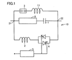
- a current limiting / tidal current control device 10 includes a series capacitor 1, a superconducting current limiting element 8, reactors 2 and 11, a bypass switch 3, a thyristor switch 4, and a control circuit 5.
- Superconducting current limiting element 8 is connected to series capacitor 1.
- a parallel circuit including a thyristor switch 4 and a reactor 2 is formed so as to be connected in parallel to a series circuit including the series capacitor 1 and the superconducting current limiting element 8.
- This parallel circuit is connected to the series circuit including the superconducting current limiting element 8 and the series capacitor 1 at connection points 21 and 22.
- a thyristor switch 4 is connected in series with the reactor 2.
- a control circuit 5 is connected to the thyristor switch 4.
- Another parallel circuit including the bypass switch 3 and the reactor 11 is formed so as to be connected in parallel with the series circuit.
- the other parallel circuit is connected to the series circuit including the superconducting current limiting element 8 and the series capacitor 1 at connection points 21 and 22.
- the bypass switch 3 is connected in series with the reactor 11. The bypass switch 3 is provided to bypass the superconducting current limiting element 8 and the like at the time of inspection of the apparatus.
- a TCSC is configured by the series capacitor 1, the reactor 2, and the thyristor switch 4.
- the impedance characteristic can be changed almost continuously from capacitive to inductive by changing the control angle. Therefore, by adjusting the impedance characteristics of the TCSC, it is possible to control the power flow of the power system to which the current limit / power flow control device 10 is connected.
- the superconducting current limiting element 8 shifts to a normal conducting state due to an overcurrent caused by the accident.
- the superconducting current limiting element 8 autonomously performs a current limiting operation.
- the thyristor switch 4 conductive, the current flowing through the superconducting current limiting element 8 can be passed through the parallel circuit including the reactor 2.
- reactor 2 functions as a current limiting reactor, and superconducting current limiting element 8 can be reliably returned to the superconducting state.
- the configuration of the current limiting / tidal current control device 10 can be simplified and control restrictions caused by the arrester and the like can be eliminated. be able to.
- the current / current control device 10 shown in FIG. 1 when an excessive current flows through the current / current control device 10 due to an accident in the power system in which the current / current control device 10 is installed, Since the current limiting operation is performed quickly and autonomously by quenching the superconducting current limiting element 8, it is possible to reliably suppress application of an overvoltage between the terminals of the series capacitor 1.
- the current flows by bypassing the superconducting current limiting element 8 by the parallel circuit including the thyristor switch 4, so that it is excessive due to the impedance (current limiting impedance) in the reactor 2.
- the processing heat energy generated in the superconducting current limiting element 8 can be reduced. As a result, the superconducting current limiting element 8 can be returned at high speed.
- Embodiment 2 With reference to FIG. 2, Embodiment 2 of the current limiting / tidal flow control device according to the present invention will be described.
- current limiting / tidal current control device 10 basically has the same structure as current limiting / current flow controlling device 10 shown in FIG. 1, but the configuration of the parallel circuit is limited to that shown in FIG. This is different from the flow / tidal flow control device 10. That is, in the current limiting / tidal current control device 10 shown in FIG. 2, the thyristor switch 4 is not disposed in the parallel circuit, and the reactor 2 and the tapped reactor 9 are connected in series to the parallel circuit. A control circuit 5 is connected to the tapped reactor 9.
- the inductance of the reactor of the parallel circuit required for the same power flow control is larger than when the thyristor switch 4 shown in FIG. 1 is used. Therefore, the effect of suppressing the fault current can be obtained from the apparatus configuration shown in FIG.
- the change rate of the inductance (L) is slower than that of the thyristor switch 4 shown in FIG.
- the current limiting / tidal current control device 10 having the configuration shown in FIG. Can be applied.
- a current / current control device 10 is a current / current control device 10 using a superconductor, and includes a superconducting current-limiting element 8 including a superconductor, a capacitor (series capacitor 1), and a parallel device. Circuit.
- the series capacitor 1 is connected in series with the superconducting current limiting element 8.
- the parallel circuit includes a reactor 2 connected in parallel to a series circuit including a superconducting current limiting element 8 and a series capacitor 1.
- the superconducting current limiting element 8 autonomously performs a current limiting operation by shifting the superconductor of the superconducting current limiting element 8 to the normal conducting state due to an overcurrent (short circuit current) at the time of the occurrence of the accident. Therefore, it is possible to reliably prevent an excessive load (excessive voltage) from being applied between the terminals of the series capacitor 1 due to the accident. Therefore, it is not necessary to install an arrester for protecting the series capacitor 1 as in the conventional device, and the configuration of the current limiting / tidal current control device 10 can be simplified. Furthermore, since the arrester is not used as in the conventional apparatus, there is no control restriction due to the return time of the arrester. In addition, since the superconducting current limiting element 8 autonomously shifts to the normal conducting state due to overcurrent, a reliable current limiting operation can be performed.
- the reactor 2 included in the parallel circuit also functions as a current limiting reactor.
- the superconducting current limiting element 8 performs a current limiting operation due to an overcurrent at the time of the accident, a current flows to a parallel circuit connected in parallel with the series circuit including the superconducting current limiting element 8 and the series capacitor 1.
- Current limiting operation can be performed by the reactor 2 of the parallel circuit.
- the parallel circuit may include a thyristor switch 4 connected in series with the reactor 2.
- the superconducting current limiting element 8 is prevented from being applied to the series capacitor 1 by the autonomous operation of the superconducting current limiting element 8 and the thyristor switch 4 is operated (full conduction). It is possible to reliably flow the current flowing through the parallel circuit. As a result, the fault current flowing through the superconducting current limiting element 8 can be reduced, and the superconducting current limiting element 8 can be returned early and reliably.
- the parallel circuit may include a tapped reactor 9 connected in series with the reactor 2.
- the inductance in the parallel circuit is larger than in the case of using the thyristor switch 4 as described above, the fault current can be suppressed more than in the case of using the thyristor switch 4.
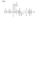
- Model system used for simulation The model system examined in the simulation with reference to FIG. 3 is a system that transmits power from the power source 14 via the transformer 15, and is connected to the secondary bus of the transformer 15. A case where a new power supply 13 is installed is assumed. The rated voltage of the transformer secondary bus 12 was 77 kV. Three transformers 15 were assumed to be operated with a rated capacity of 250 MVA. The short-circuit impedance of the transformer 15 was assumed to be 22% (self-capacitance basis).
- the transient reactance Xd 'of the newly established power supply 13 is assumed to be 20% (based on the self-capacitance).
- the current limiting / tidal current control device 10 is installed at a power transmission end of a line connecting the bus 12 to the power transmission line 16. That is, the bus 12 and the two power transmission lines 16 are connected via the current limiting / tidal current control device 10.
- Breakers 18 are installed at both ends of the transmission line 16.
- the model system shown in FIG. 3 is a case where the short-circuit current exceeds the rated breaker current 31.5 kA of the circuit breaker unless the current limiting / tidal current control device 10 is installed as will be described later.
- the back impedance of the system is 29.33%@1000 MVA from the short-circuit impedance of the transformer 15 and the transient reactance of the new power supply 13 is 66.7%@1000 MVA
- the combined impedance of the new power supply 13 and the back system is 20. 4% @ 1000 MVA.
- the short circuit current Is at the time of the three-phase short circuit of the bus 12 closest to the bus 12 is 36.8 kA.
- model system is a radial system that is relatively easy to study in order to verify current-limiting operation.
- the configuration of the current / tidal flow control device 10 is the same as that of the current / current control device 10 shown in FIG. In the following simulation, in order to facilitate the verification of the current limiting operation, the simulation was performed under the condition that the two-line collective compensation is performed by the current limiting / tidal current control device 10 as shown in FIG.
- the transmission power on the stability is 80 MW or less (per line). Therefore, even when one line is transmitted, 160 MW can be transmitted if the line reactance X1 (50 km) is compensated by 50%.
- the transmission capacity is increased by compensating X1 (50 km) of the transmission line 16 by 50% (equivalent to 25 km), and the transmission power of two 77 kV transmission lines is 160 MW.
- the condition was as follows.
- the reactance at the steady state is set to 50% compensation of the line reactance.
- the constant current flowing through the series capacitor 1 and the reactor 2 during two-line power transmission is determined to be less than twice the line current.
- this condition is that the fixed reactance (X) is j0.2 pu and the angle from the voltage peak is ⁇ , 30 ° ⁇ the firing angle ⁇ ⁇ 40. It was realized by using within the range of °.
- XL when the thyristor switch 4 is fully conducted is a fixed reactance (X) j0.2pu.
- the inductive reactance XL of the reactor 2 necessary for suppressing the short-circuit current was examined.
- the characteristics of the current limiting / tidal current control device 10 satisfying such conditions were determined as follows.
- the inductive reactance (XL) of the reactor 2 that functions as the current limiting reactor of the current limiting / tidal current control device 10 according to the embodiment, and the combined impedance 20.4% @
- the operation start current of the superconducting current limiting element 8 in the current limiting / tidal current control device 10 is 4800 Arms (6.7 kAp). This value is a value that is twice the steady current (2400 A) flowing through the superconducting current limiting element. Further, the current limiting resistance in the normal conducting state of the superconducting current limiting element 8 was 8 ⁇ .
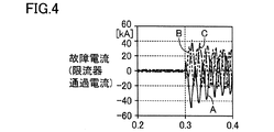
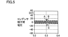
- ⁇ Result> 4 to 6 show simulation results when the current limiting / tidal flow control device 10 according to the present invention is applied.
- the horizontal axis of each graph represents time, and the vertical axis of the graph of FIG. 4 represents a fault current (current passing through the current / current control device).
- the unit of fault current is kA.
- the vertical axis in FIG. 5 is the voltage across the capacitor terminals in the series capacitor of the current limiting / tidal current control device 10, and the unit is kV.
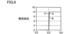
- shaft of FIG. 6 has shown the current limiting resistance,
- the unit is (omega
- the components of the three phases in the passing current of the current limiting / tidal current control device are shown as graph A, graph B, and graph C, respectively.
- the magnitude of the voltage across the capacitor terminals of the series capacitor 1 in the current limiting / tidal current control device 10 at the time of failure is immediately after the failure because of the effect of a slight operation delay of the current limiting device. Although an overvoltage of about 3.2 pu is generated in the half-wave, the voltage is suppressed to the same level as the steady voltage thereafter.
- the present invention is particularly advantageously applied to a current limiting / tidal current control device including a superconducting current limiting element.
Landscapes
- Engineering & Computer Science (AREA)
- Power Engineering (AREA)
- Emergency Protection Circuit Devices (AREA)
- Containers, Films, And Cooling For Superconductive Devices (AREA)
Abstract
Description
図1を参照して、本発明による限流・潮流制御装置を説明する。本発明による限流・潮流制御装置10は、直列コンデンサ1と、超電導限流素子8と、リアクトル2、11と、バイパススイッチ3と、サイリスタスイッチ4と、制御回路5とを備える。超電導限流素子8は直列コンデンサ1と接続されている。直列コンデンサ1と超電導限流素子8とからなる直列回路と並列に接続されるように、サイリスタスイッチ4およびリアクトル2を含む並列回路が形成されている。この並列回路は、超電導限流素子8と直列コンデンサ1とからなる上記直列回路と、接続ポイント21、22において接続されている。並列回路においては、リアクトル2と直列にサイリスタスイッチ4が接続されている。サイリスタスイッチ4には制御回路5が接続されている。上記直列回路と並列に接続されるように、バイパススイッチ3およびリアクトル11を含む他の並列回路が形成されている。当該他の並列回路は、超電導限流素子8と直列コンデンサ1とからなる上記直列回路と、接続ポイント21、22において接続されている。当該他の並列回路においては、リアクトル11と直列にバイパススイッチ3が接続されている。バイパススイッチ3は、装置の点検時に超電導限流素子8などをバイパスするために設けられている。
図2を参照して、本発明による限流・潮流制御装置の実施の形態2を説明する。
以下、本発明の効果を確認するためシミュレーションを行なった。
(1) シミュレーションに用いたモデル系統について
図3を参照して、シミュレーションにおいて検討したモデル系統は、電源14から変圧器15を介して送電している系統であり、変圧器15の2次母線に新しく電源13が設置されたケースを想定している。変圧器2次母線12の定格電圧は77kVとした。変圧器15は、定格容量250MVAの3台運用を想定した。変圧器15の短絡インピーダンスは22%(自己容量ベース)と想定した。
送電線16の送電容量については、77kV用の送電線として適用される送電線のうち比較的容量の大きい送電線を想定し、熱的な条件で決まる1回線の常時容量は170MWとした。
限流・潮流制御装置10の直列コンデンサ1の容量性リアクタンスXc、およびリアクトル2の誘導性リアクタンスXLについて、以下のように検討した。
想定した故障種別としては、図3に示した事故点17において3相短絡(3LS)が発生したと想定した(電源側母線至近端3LS)。故障シーケンスとしては、時刻T=0.3秒において3相短絡が発生し、時刻T=0.4秒において遮断器18が動作し(CB両端開放)、故障回線が遮断される。そして、時刻T=0.6秒において、限流器(超電導限流素子8)が定常状態へ復帰するとした。
図4~6に、本発明による限流・潮流制御装置10を適用した場合のシミュレーションの結果を示す。図4~6において、各グラフの横軸は時間であり、図4のグラフの縦軸は故障電流(限流・潮流制御装置通過電流)を表わしている。なお、故障電流の単位はkAである。また、図5の縦軸は限流・潮流制御装置10の直列コンデンサにおけるコンデンサ端子間電圧であり、その単位はkVである。また、図6の縦軸は限流抵抗を示しており、その単位はΩである。図4から分かるように、本発明の実施例においては、直流分を除いた短絡電流の交流成分は30kArms(=42.4kAp以下に抑制されており、適切に限流されている。なお、図4~図6では、限流・潮流制御装置の通過電流における3相のそれぞれの成分をグラフA、グラフB、グラフCとして示している。
新設電源、14 電源、15 変圧器、17 事故点、18 遮断器、21,22 接続ポイント。
Claims (4)
- 超電導体を利用した限流・潮流制御装置であって、
前記超電導体を含む超電導限流素子と、
前記超電導限流素子と直列に接続されたコンデンサと、
前記超電導限流素子と前記コンデンサとを含む直列回路に並列に接続されたリアクトルを含む並列回路とを備える、限流・潮流制御装置。 - 前記並列回路に含まれる前記リアクトルは限流リアクトルとして機能する、請求項1に記載の限流・潮流制御装置。
- 前記並列回路は、前記リアクトルと直列に接続されたサイリスタスイッチを含む、請求項1または2に記載の限流・潮流制御装置。
- 前記並列回路は、前記リアクトルと直列に接続されたタップ付きリアクトルを含む、請求項1または2に記載の限流・潮流制御装置。
Priority Applications (5)
| Application Number | Priority Date | Filing Date | Title |
|---|---|---|---|
| ES14779757T ES2759913T3 (es) | 2013-04-01 | 2014-03-26 | Dispositivo de control de flujo/limitación de corriente |
| US14/770,998 US9762051B2 (en) | 2013-04-01 | 2014-03-26 | Current-limiting and power-flow control device |
| CN201480019156.2A CN105103397B (zh) | 2013-04-01 | 2014-03-26 | 限流和潮流控制装置 |
| KR1020157031202A KR20150136534A (ko) | 2013-04-01 | 2014-03-26 | 한류·조류 제어 장치 |
| EP14779757.5A EP2983263B1 (en) | 2013-04-01 | 2014-03-26 | Current-limiting/flow control device |
Applications Claiming Priority (2)
| Application Number | Priority Date | Filing Date | Title |
|---|---|---|---|
| JP2013-075938 | 2013-04-01 | ||
| JP2013075938A JP2014204460A (ja) | 2013-04-01 | 2013-04-01 | 限流・潮流制御装置 |
Publications (1)
| Publication Number | Publication Date |
|---|---|
| WO2014162949A1 true WO2014162949A1 (ja) | 2014-10-09 |
Family
ID=51658247
Family Applications (1)
| Application Number | Title | Priority Date | Filing Date |
|---|---|---|---|
| PCT/JP2014/058535 Ceased WO2014162949A1 (ja) | 2013-04-01 | 2014-03-26 | 限流・潮流制御装置 |
Country Status (7)
| Country | Link |
|---|---|
| US (1) | US9762051B2 (ja) |
| EP (1) | EP2983263B1 (ja) |
| JP (1) | JP2014204460A (ja) |
| KR (1) | KR20150136534A (ja) |
| CN (1) | CN105103397B (ja) |
| ES (1) | ES2759913T3 (ja) |
| WO (1) | WO2014162949A1 (ja) |
Cited By (2)
| Publication number | Priority date | Publication date | Assignee | Title |
|---|---|---|---|---|
| CN112165078A (zh) * | 2020-06-15 | 2021-01-01 | 国网湖北省电力有限公司黄冈供电公司 | 一种利用短路电流变化率的谐振型限流器投入控制方法 |
| CN121529460A (zh) * | 2026-01-15 | 2026-02-13 | 杭州布雷科电气有限公司 | 基于igbt和接触器的可切换串并联限流电路的离散组合优化控制方法 |
Families Citing this family (4)
| Publication number | Priority date | Publication date | Assignee | Title |
|---|---|---|---|---|
| JP6069073B2 (ja) * | 2013-04-01 | 2017-01-25 | 住友電気工業株式会社 | 限流装置 |
| KR101622187B1 (ko) * | 2014-05-13 | 2016-05-18 | 엘에스산전 주식회사 | 한류기 |
| KR102077528B1 (ko) * | 2019-07-11 | 2020-02-14 | 아이에프텍(주) | Iot 기반의 무정전 전원 공급 장치의 연결 구조 및 그 제어 방법 |
| CN111541231A (zh) * | 2020-05-19 | 2020-08-14 | 中天集团上海超导技术有限公司 | 一种增强三相同轴式超导电缆抗故障电流能力的方法 |
Citations (5)
| Publication number | Priority date | Publication date | Assignee | Title |
|---|---|---|---|---|
| JPH04207924A (ja) * | 1990-11-30 | 1992-07-29 | Tokyo Electric Power Co Inc:The | 超電導限流装置 |
| JPH09130966A (ja) * | 1995-11-01 | 1997-05-16 | Nissin Electric Co Ltd | 超電導限流装置 |
| JPH11146555A (ja) * | 1997-11-05 | 1999-05-28 | Toshiba Corp | 超電導限流装置 |
| JP2004350337A (ja) * | 2003-05-20 | 2004-12-09 | National Institute Of Advanced Industrial & Technology | 限流機能付き潮流制御装置 |
| JP2007236108A (ja) * | 2006-03-01 | 2007-09-13 | Toshiba Corp | 超電導限流装置および電力システム |
Family Cites Families (17)
| Publication number | Priority date | Publication date | Assignee | Title |
|---|---|---|---|---|
| DE1932379C3 (de) * | 1969-06-26 | 1978-05-11 | Siemens Ag, 1000 Berlin Und 8000 Muenchen | Spule mit veränderlicher Induktivität als Strombegrenzungseinrichtung für Energieübertragungsanlagen |
| JP2901068B2 (ja) | 1988-10-07 | 1999-06-02 | 株式会社東芝 | 限流装置 |
| JPH02116184A (ja) * | 1988-10-26 | 1990-04-27 | Toshiba Corp | パルスレーザ電源装置 |
| JP2941833B2 (ja) | 1989-01-27 | 1999-08-30 | 株式会社東芝 | 超電導限流装置 |
| JPH03245725A (ja) | 1990-02-22 | 1991-11-01 | Takaoka Electric Mfg Co Ltd | 過電流限流装置 |
| JPH07209371A (ja) * | 1994-01-21 | 1995-08-11 | Fuji Electric Co Ltd | ケーブルの交流耐電圧試験装置および方法 |
| JPH0974682A (ja) * | 1995-09-04 | 1997-03-18 | Hitachi Ltd | 直列コンデンサ制御装置 |
| JP2000090788A (ja) | 1998-09-09 | 2000-03-31 | Toshiba Corp | 限流装置及び限流遮断装置 |
| JP2001078362A (ja) * | 1999-09-07 | 2001-03-23 | Toshiba Corp | 電力系統安定化装置 |
| DE19963181C2 (de) | 1999-12-27 | 2002-04-18 | Siemens Ag | Resistive Strombegrenzereinrichtung für Gleich- oder Wechselstrom mit wenigstens einer Leiterbahn mit Hoch-T¶c¶-Supraleitermaterial |
| KR100780706B1 (ko) * | 2006-08-17 | 2007-11-30 | 엘에스산전 주식회사 | 복합형 초전도 한류기 |
| US20080056327A1 (en) * | 2006-08-30 | 2008-03-06 | Hatch Ltd. | Method and system for predictive electrode lowering in a furnace |
| KR100888147B1 (ko) | 2007-08-20 | 2009-03-13 | 한국전력공사 | 하이브리드 초전도 한류기 |
| CN101183129A (zh) | 2007-11-26 | 2008-05-21 | 天津理工大学 | 一种失超型超导故障限流器的故障检测系统及其检测方法 |
| JP5187750B2 (ja) * | 2008-07-04 | 2013-04-24 | 株式会社前川製作所 | 磁気飽和型限流器 |
| CN102035196A (zh) * | 2010-12-30 | 2011-04-27 | 东南大学 | 一种基于可控串补的故障限流装置 |
| CN102646968B (zh) * | 2012-05-04 | 2015-03-18 | 中国科学院电工研究所 | 一种电抗器型短路故障限流器 |
-
2013
- 2013-04-01 JP JP2013075938A patent/JP2014204460A/ja active Pending
-
2014
- 2014-03-26 CN CN201480019156.2A patent/CN105103397B/zh not_active Expired - Fee Related
- 2014-03-26 EP EP14779757.5A patent/EP2983263B1/en active Active
- 2014-03-26 ES ES14779757T patent/ES2759913T3/es active Active
- 2014-03-26 WO PCT/JP2014/058535 patent/WO2014162949A1/ja not_active Ceased
- 2014-03-26 US US14/770,998 patent/US9762051B2/en not_active Expired - Fee Related
- 2014-03-26 KR KR1020157031202A patent/KR20150136534A/ko not_active Ceased
Patent Citations (5)
| Publication number | Priority date | Publication date | Assignee | Title |
|---|---|---|---|---|
| JPH04207924A (ja) * | 1990-11-30 | 1992-07-29 | Tokyo Electric Power Co Inc:The | 超電導限流装置 |
| JPH09130966A (ja) * | 1995-11-01 | 1997-05-16 | Nissin Electric Co Ltd | 超電導限流装置 |
| JPH11146555A (ja) * | 1997-11-05 | 1999-05-28 | Toshiba Corp | 超電導限流装置 |
| JP2004350337A (ja) * | 2003-05-20 | 2004-12-09 | National Institute Of Advanced Industrial & Technology | 限流機能付き潮流制御装置 |
| JP2007236108A (ja) * | 2006-03-01 | 2007-09-13 | Toshiba Corp | 超電導限流装置および電力システム |
Non-Patent Citations (2)
| Title |
|---|
| See also references of EP2983263A4 |
| YUJI YAMAZAKI ET AL.: "Development of TCSC Application to Fault Current Limiters", IEEJ TRANSACTIONS ON POWER AND ENERGY, THE INSTITUTE OF ELECTRICAL ENGINEERS OF JAPAN, vol. 121, no. 4, 2001, pages 514 - 519 |
Cited By (3)
| Publication number | Priority date | Publication date | Assignee | Title |
|---|---|---|---|---|
| CN112165078A (zh) * | 2020-06-15 | 2021-01-01 | 国网湖北省电力有限公司黄冈供电公司 | 一种利用短路电流变化率的谐振型限流器投入控制方法 |
| CN112165078B (zh) * | 2020-06-15 | 2022-07-05 | 国网湖北省电力有限公司黄冈供电公司 | 一种利用短路电流变化率的谐振型限流器投入控制方法 |
| CN121529460A (zh) * | 2026-01-15 | 2026-02-13 | 杭州布雷科电气有限公司 | 基于igbt和接触器的可切换串并联限流电路的离散组合优化控制方法 |
Also Published As
| Publication number | Publication date |
|---|---|
| CN105103397A (zh) | 2015-11-25 |
| EP2983263A4 (en) | 2017-01-11 |
| EP2983263B1 (en) | 2019-11-06 |
| KR20150136534A (ko) | 2015-12-07 |
| CN105103397B (zh) | 2019-01-11 |
| JP2014204460A (ja) | 2014-10-27 |
| US9762051B2 (en) | 2017-09-12 |
| ES2759913T3 (es) | 2020-05-12 |
| EP2983263A1 (en) | 2016-02-10 |
| US20160020604A1 (en) | 2016-01-21 |
Similar Documents
| Publication | Publication Date | Title |
|---|---|---|
| WO2014162949A1 (ja) | 限流・潮流制御装置 | |
| JP6069073B2 (ja) | 限流装置 | |
| CN110544931A (zh) | 一种自产供电相电源的接地故障电流补偿系统及方法 | |
| CN110571778A (zh) | 一种自产供电相电源的接地故障电流补偿系统及方法 | |
| Salcedo et al. | Long duration overvoltages due to current backfeeding in secondary networks | |
| CN207625293U (zh) | 一种串并联混合型补偿器 | |
| CN110690688A (zh) | 一种避雷器保护装置及避雷器保护方法 | |
| Bhardwaj et al. | Installation of Automatically Controlled Compensation Banks | |
| CN103280819B (zh) | 一种变电站的并联电抗器补偿回路及其补偿方法 | |
| Aloh et al. | Evaluating the Performance of Unified Power Flow Controller (UPFC) On Fault Current Limitation in the Nigrian 330kv Power System | |
| Golshani et al. | Facts based fault current limiter utilization in HV grid | |
| Boribun et al. | Comparative study on a fault current limiter with thyristor-controlled impedances | |
| CN207612063U (zh) | 一种串联补偿器 | |
| Sharma et al. | Application of solid state fault current limiter on express feeder for voltage sag mitigation | |
| Komatsu et al. | Fault current limitation using thyristor based devices | |
| Kirubavathi et al. | Fault Current and Overvoltage Limitation in a Distribution Network with Distributed Generation units Through Superconducting Fault Current Limiter | |
| Klucznik et al. | Resonance problems in UHV transmission lines | |
| Nayak et al. | Series Compensation on 400 kV Transmission Line-A Few Design Aspects | |
| Volkov et al. | The Effect of Current-Limiting Reactors on the Tripping of Short Circuits in High-Voltage Electrical Equipment | |
| Štumberger et al. | Medium-voltage distribution feeders in closed-loop arrangement–neutral point grounding | |
| Patcharoen et al. | Inrush current analysis for switching large shunt capacitor bank in a 230 kV substation system | |
| Komatsu et al. | Experimental setup of fault current limiters | |
| Desrosiers et al. | Expression of rate of rise of recovery voltage across a circuit breaker with fault current limiter in bus-tie location | |
| Nzeba et al. | Protection of Reactors and FACTS Devices | |
| Zhang et al. | Research on the applications of differential protection in TCT controllable shunt reactor |
Legal Events
| Date | Code | Title | Description |
|---|---|---|---|
| WWE | Wipo information: entry into national phase |
Ref document number: 201480019156.2 Country of ref document: CN |
|
| 121 | Ep: the epo has been informed by wipo that ep was designated in this application |
Ref document number: 14779757 Country of ref document: EP Kind code of ref document: A1 |
|
| WWE | Wipo information: entry into national phase |
Ref document number: 14770998 Country of ref document: US |
|
| NENP | Non-entry into the national phase |
Ref country code: DE |
|
| WWE | Wipo information: entry into national phase |
Ref document number: 2014779757 Country of ref document: EP |
|
| ENP | Entry into the national phase |
Ref document number: 20157031202 Country of ref document: KR Kind code of ref document: A |