WO2014163044A1 - 水素製造手段を備えた太陽光発電システム - Google Patents
水素製造手段を備えた太陽光発電システム Download PDFInfo
- Publication number
- WO2014163044A1 WO2014163044A1 PCT/JP2014/059471 JP2014059471W WO2014163044A1 WO 2014163044 A1 WO2014163044 A1 WO 2014163044A1 JP 2014059471 W JP2014059471 W JP 2014059471W WO 2014163044 A1 WO2014163044 A1 WO 2014163044A1
- Authority
- WO
- WIPO (PCT)
- Prior art keywords
- power
- power generation
- hydrogen
- generation system
- solar
- Prior art date
- Legal status (The legal status is an assumption and is not a legal conclusion. Google has not performed a legal analysis and makes no representation as to the accuracy of the status listed.)
- Ceased
Links
Images


Classifications
-
- H—ELECTRICITY
- H02—GENERATION; CONVERSION OR DISTRIBUTION OF ELECTRIC POWER
- H02S—GENERATION OF ELECTRIC POWER BY CONVERSION OF INFRARED RADIATION, VISIBLE LIGHT OR ULTRAVIOLET LIGHT, e.g. USING PHOTOVOLTAIC [PV] MODULES
- H02S10/00—PV power plants; Combinations of PV energy systems with other systems for the generation of electric power
-
- C—CHEMISTRY; METALLURGY
- C25—ELECTROLYTIC OR ELECTROPHORETIC PROCESSES; APPARATUS THEREFOR
- C25B—ELECTROLYTIC OR ELECTROPHORETIC PROCESSES FOR THE PRODUCTION OF COMPOUNDS OR NON-METALS; APPARATUS THEREFOR
- C25B1/00—Electrolytic production of inorganic compounds or non-metals
- C25B1/01—Products
- C25B1/02—Hydrogen or oxygen
- C25B1/04—Hydrogen or oxygen by electrolysis of water
-
- C—CHEMISTRY; METALLURGY
- C25—ELECTROLYTIC OR ELECTROPHORETIC PROCESSES; APPARATUS THEREFOR
- C25B—ELECTROLYTIC OR ELECTROPHORETIC PROCESSES FOR THE PRODUCTION OF COMPOUNDS OR NON-METALS; APPARATUS THEREFOR
- C25B15/00—Operating or servicing cells
- C25B15/02—Process control or regulation
-
- C—CHEMISTRY; METALLURGY
- C25—ELECTROLYTIC OR ELECTROPHORETIC PROCESSES; APPARATUS THEREFOR
- C25B—ELECTROLYTIC OR ELECTROPHORETIC PROCESSES FOR THE PRODUCTION OF COMPOUNDS OR NON-METALS; APPARATUS THEREFOR
- C25B9/00—Cells or assemblies of cells; Constructional parts of cells; Assemblies of constructional parts, e.g. electrode-diaphragm assemblies; Process-related cell features
- C25B9/70—Assemblies comprising two or more cells
- C25B9/73—Assemblies comprising two or more cells of the filter-press type
-
- H—ELECTRICITY
- H02—GENERATION; CONVERSION OR DISTRIBUTION OF ELECTRIC POWER
- H02J—ELECTRIC POWER NETWORKS; CIRCUIT ARRANGEMENTS OR SYSTEMS FOR SUPPLYING OR DISTRIBUTING ELECTRIC POWER; SYSTEMS FOR STORING ELECTRIC ENERGY
- H02J3/00—Circuit arrangements for AC mains or AC distribution networks
- H02J3/38—Arrangements for feeding a single network from two or more generators or sources in parallel; Arrangements for feeding already energised networks from additional generators or sources in parallel
- H02J3/381—Dispersed generators
-
- H—ELECTRICITY
- H02—GENERATION; CONVERSION OR DISTRIBUTION OF ELECTRIC POWER
- H02J—ELECTRIC POWER NETWORKS; CIRCUIT ARRANGEMENTS OR SYSTEMS FOR SUPPLYING OR DISTRIBUTING ELECTRIC POWER; SYSTEMS FOR STORING ELECTRIC ENERGY
- H02J2101/00—Supply or distribution of decentralised, dispersed or local electric power generation
- H02J2101/20—Dispersed power generation using renewable energy sources
- H02J2101/22—Solar energy
- H02J2101/24—Photovoltaics
- H02J2101/25—Photovoltaics involving maximum power point tracking control for photovoltaic sources
-
- Y—GENERAL TAGGING OF NEW TECHNOLOGICAL DEVELOPMENTS; GENERAL TAGGING OF CROSS-SECTIONAL TECHNOLOGIES SPANNING OVER SEVERAL SECTIONS OF THE IPC; TECHNICAL SUBJECTS COVERED BY FORMER USPC CROSS-REFERENCE ART COLLECTIONS [XRACs] AND DIGESTS
- Y02—TECHNOLOGIES OR APPLICATIONS FOR MITIGATION OR ADAPTATION AGAINST CLIMATE CHANGE
- Y02E—REDUCTION OF GREENHOUSE GAS [GHG] EMISSIONS, RELATED TO ENERGY GENERATION, TRANSMISSION OR DISTRIBUTION
- Y02E10/00—Energy generation through renewable energy sources
- Y02E10/50—Photovoltaic [PV] energy
- Y02E10/56—Power conversion systems, e.g. maximum power point trackers
-
- Y—GENERAL TAGGING OF NEW TECHNOLOGICAL DEVELOPMENTS; GENERAL TAGGING OF CROSS-SECTIONAL TECHNOLOGIES SPANNING OVER SEVERAL SECTIONS OF THE IPC; TECHNICAL SUBJECTS COVERED BY FORMER USPC CROSS-REFERENCE ART COLLECTIONS [XRACs] AND DIGESTS
- Y02—TECHNOLOGIES OR APPLICATIONS FOR MITIGATION OR ADAPTATION AGAINST CLIMATE CHANGE
- Y02E—REDUCTION OF GREENHOUSE GAS [GHG] EMISSIONS, RELATED TO ENERGY GENERATION, TRANSMISSION OR DISTRIBUTION
- Y02E60/00—Enabling technologies; Technologies with a potential or indirect contribution to GHG emissions mitigation
- Y02E60/30—Hydrogen technology
- Y02E60/36—Hydrogen production from non-carbon containing sources, e.g. by water electrolysis
-
- Y—GENERAL TAGGING OF NEW TECHNOLOGICAL DEVELOPMENTS; GENERAL TAGGING OF CROSS-SECTIONAL TECHNOLOGIES SPANNING OVER SEVERAL SECTIONS OF THE IPC; TECHNICAL SUBJECTS COVERED BY FORMER USPC CROSS-REFERENCE ART COLLECTIONS [XRACs] AND DIGESTS
- Y02—TECHNOLOGIES OR APPLICATIONS FOR MITIGATION OR ADAPTATION AGAINST CLIMATE CHANGE
- Y02P—CLIMATE CHANGE MITIGATION TECHNOLOGIES IN THE PRODUCTION OR PROCESSING OF GOODS
- Y02P20/00—Technologies relating to chemical industry
- Y02P20/10—Process efficiency
- Y02P20/133—Renewable energy sources, e.g. sunlight
Definitions
- the present invention relates to a system that supplies solar energy as electric energy with high efficiency, and a configuration and drive control method for a system that stores chemical energy as chemical energy.
- a solar power generation system is a system that converts DC power generated by a solar cell into AC power using a power conditioner (PCS), and generally supplies power to a load in conjunction with a grid.
- PCS power conditioner
- this type of PCS is, for example, MPPT (Maximum Power called “maximum power tracking control” described in Patent Document 1 and Patent Document 2). It has a function to obtain high output power by (Point Tracking) control.
- the PCS generally has input / output power specifications determined by a conversion circuit, element selection, and the like. That is, the specification value of the rated output of the PCS becomes the maximum power value of the reverse power flow to the system.
- the solar panel is generally constructed by constructing a solar cell array in which the solar panel rated output, the number of sheets, the configuration and the like are adjusted according to the input / output specifications of the PCS, and the solar power generation system is constructed.
- the solar radiation intensity that falls on the ground is about 1 kW / m 2
- the actual number of days that energy near the rated output of the solar panel can be obtained because it causes energy scattering and absorption in the atmosphere. Less throughout the year. That is, when the solar cell array is configured with an output specification equivalent to the output specification value of the PCS, the rate at which the maximum output value is output from the PCS is very small.
- the PCS has excellent conversion efficiency when the input power is large, but has a characteristic that the conversion efficiency is greatly reduced particularly when the input power is smaller than the rated output. Therefore, when a solar cell array is configured with an output specification equivalent to the rated output of the PCS, the input power from the solar cell array tends to be lower than the rated output of the PCS, and solar power generation due to a decrease in PCS conversion efficiency It becomes a factor of system efficiency reduction.
- Patent Document 3 a plurality of PCSs having different rated capacities are provided, and the input rate of the input power with respect to the rated capacity of the PCS is a predetermined value or more according to the input power from the DC power supply (solar power generation). It has been proposed to select the PCS so that
- JP 2008-3000745 A Japanese Patent Laid-Open No. 2005-235082 JP 2010-98792 A
- An object of the present invention is to provide a solar power generation system capable of efficiently using solar power generation energy and supplying high-efficiency power.
- the inventors have found that the above problems can be solved, and have completed the present invention.
- the solar power generation system including the hydrogen production means for storing solar energy includes a solar power generation device that converts solar energy into direct current power, and direct current power obtained by the solar power generation device.
- a power conversion controller having an output control function for converting the power into AC power and obtaining maximum power, hydrogen production means for producing hydrogen using DC power obtained by the solar power generation device, and the solar power generation switch for switching a power detection means for detecting the output power W 2 output power W 1 and the power converter controller of the apparatus, the electrical connection structure of the said solar generator power converter controller and the hydrogen production unit
- a control unit that transmits a control signal to the switching unit, and the rated output power of the photovoltaic power generation device is larger than the rated output power of the power conversion controller Are urchin set, the control unit is configured with a power prediction means for predicting the generation predicted power W 0 that can be generated by the solar power generation device, the power the power detection and the power generation predicted power W 0 estimated by the prediction means
- the switching means is controlled according to the comparison result
- FIG. It is a figure showing the photovoltaic power generation equivalent circuit schematic of the photovoltaic power generation system provided with the hydrogen production means concerning a 1st embodiment of the present invention. It is a figure showing the voltage-current characteristic change by the serial resistance component of the solar energy power generation system provided with the hydrogen production means which concerns on 1st Embodiment of this invention. It is a figure showing the voltage power characteristic change by the series resistance component of the solar energy power generation system provided with the hydrogen production means which concerns on 1st Embodiment of this invention.
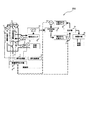
- FIG. 1 is a diagram schematically illustrating the configuration of a photovoltaic power generation system including a hydrogen production unit according to the first embodiment of the present invention.
- a solid line represents an electrical wiring
- a broken line represents a switching signal output line
- a dotted line represents a signal measurement line, which is a wiring that connects each means and represents transmission and reception of signals and energy.
- the photovoltaic power generation system 100 provided with the hydrogen production means is capable of using, storing and supplying solar energy with high efficiency.
- the solar power generation system 100 provided with the hydrogen production means is an alternating current between the solar power generation apparatus 1 as the renewable energy power generation means, the hydrogen production apparatus 2 as the hydrogen production means, and the optimum DC power of the solar power generation power.
- a power conversion controller 3 for converting into electric power, a switching means 4 for switching the electrical connection configuration of the hydrogen production device 2 and the power conversion controller 3, an output power W 1 output from the solar power generation device 1, and a power detection means for detecting the output power W 2 output from the power conversion controller 3 (the power detector 11, 12) is configured to include at least a control unit 6 for controlling the entire system.
- the rated output power of the solar power generation device 1 is made larger than the rated output power of the power conversion controller 3.
- the conversion efficiency of the power conversion controller 3 is improved under conditions of low solar radiation intensity as compared with the case where the rated output power of the solar power generation device 1 and the power conversion controller 3 is set to the same output specification. Yes.
- Solar energy which is renewable energy, is based on global weather conditions without any electrical or physical connection lines, piping, or the like with the solar power generation device 1.
- the solar power generation device 1 is a device that converts solar energy into DC power, and is electrically connected to the hydrogen production device 2 and the power conversion controller 3, and the electrical connection configuration is switched by the switching means 4.
- the electric power generated by the solar power generation device 1 is supplied to the system via the power conversion controller 3. Further, by connecting the solar power generation device 1 and the hydrogen production device 2 by the switching means 4, the electric power generated by the solar power generation device 1 is supplied to the hydrogen production device 2, and the electric power is supplied to the hydrogen energy by the hydrogen production device 2. Electric power is stored and supplied as chemical energy.
- the hydrogen production device 2 produces hydrogen using the electric power obtained by the solar power generation device 1. Specifically, in the hydrogen production apparatus 2, at least hydrogen is generated by electrolyzing the electrolytic solution using these electric powers. Therefore, the more electric power is supplied from the solar power generation device 1 to the hydrogen production device 2, the more hydrogen is produced in the hydrogen production device 2.
- the hydrogen production device 2 is electrically connected to the solar power generation device 1 via the switching means 4.
- the specific configuration of the hydrogen production apparatus 2 is not particularly limited, but the hydrogen production apparatus 2 includes, for example, an electrolytic solution, an electrolyte, an electrode catalyst for promoting the reaction provided so as to sandwich the electrolyte, and external power.
- An electrolysis cell holding a current collector to be supplied is provided. Then, water is electrolyzed by this electrode catalyst, and hydrogen and oxygen are generated.
- the electrolysis cell or an electrolysis stack in which electrolysis cells are laminated in multiple layers is defined as a hydrogen production apparatus 2.
- the hydrogen production apparatus 2 is configured by connecting a plurality of electrolysis stacks so that the electrical connection configuration can be switched.
- the electrolyte solution is not particularly limited as long as at least hydrogen is generated by electrolysis, but is preferably a compound that exhibits alkalinity when dissolved in water, such as potassium hydroxide. By using such a compound, the hydrogen production apparatus 2 that is inexpensive and hardly corrodes can be obtained.
- the electrolyte for example, an ion conductive solid polymer electrolyte can be used.
- the thus configured hydrogen production apparatus 2 can be operated at a low temperature, and has the advantage that it can be started in a short time.
- Water electrolysis conditions are not particularly limited, and can be any conditions as long as at least hydrogen can be generated. However, when increasing the temperature during electrolysis in order to increase the electrolysis efficiency, a temperature control algorithm must be considered.
- the power conversion controller 3 mainly has a high output by MPPT (Maximum Power Point Tracking) control called maximum power tracking control in order to efficiently convert power from the solar cell in addition to a power conversion circuit such as a booster circuit and an inverter circuit. It has a function to obtain electric power.
- MPPT Maximum Power Point Tracking
- the MPPT control method is not particularly limited as long as it is a system capable of converting the maximum power generated by the solar cell into AC power with a power conditioner and interconnecting the grid to supply power to the outside.
- the switching means 4 only needs to have a function capable of being electrically cut off and conducted in response to a command from the control signal output unit 8, and the parts material and configuration are not particularly limited.
- the parts material and configuration are not particularly limited.
- mechanical contact switches, relays, semiconductor switch elements, etc. can be freely selected.
- the electrical specifications must be matched at the design stage, and switching means that matches the system scale can be selected.
- FIG. 3A An example of a connection configuration switched by the switching means 4 is shown in FIG.
- the configuration (1) in FIG. 3A is a configuration in which only the power conversion control 3 is electrically connected to the solar power generation device 1 by cutting off the switches 4a, 4c, and 4d in FIG.
- the configuration (2) in FIG. 3B is a configuration in which the switches 4b and 4c in FIG. 1 are cut off and the switches 4a and 4d are turned on to connect the hydrogen generator 2 and the power conversion control 3 in series to the solar power generation device 1. is there.
- the configuration (3) in FIG. 3C is a configuration in which the switch 4d in FIG. 1 is cut off and the switches 4a, 4b, and 4c are turned on to connect the hydrogen generator 2 and the power conversion control 3 in parallel to the solar power generation device 1. is there.
- the configuration (4) in FIG. 3D is a configuration in which only the hydrogen production device 2 is electrically connected to the solar power generation device 1 by cutting off the switches 4b and 4d in FIG.
- the control unit 6 includes a signal processing unit 7 that processes each measurement signal, a control signal output unit 8 that outputs a control signal to the switching unit 4, and a signal calculation unit 9.
- the signal calculation unit 9 performs calculations such as calculation of the power generation predicted power W 0 of the solar power generation apparatus from the panel temperature estimated from the voltage and current of the solar array output and the estimated amount of solar radiation intensity.
- the solar power generation device 1 generates DC power using solar energy.
- the generated DC power is converted into AC power via the power conversion controller 3 and supplied to the system.
- the power generation predicted power W 0 of the solar power generation device 1 varies in accordance with the temporal change in solar radiation intensity of solar energy that is a renewable energy source.
- the predicted power generation power W 0 of the solar power generation device 1 exceeds the rated output power of the power conversion controller 3 There is.
- the solar power generation device 1 does not generate power exceeding the rated output power of the power conversion controller 3. It will not be available.
- the switching unit 4 switches the connection configuration so that the connection configuration of the hydrogen production device 2 and the power conversion controller 3 is connected in series and / or parallel to the photovoltaic power generation device.
- surplus power exceeding the rated output power of the power conversion controller 3 is supplied to the hydrogen production device 2, electrolysis starts, and hydrogen is generated.
- the output power W 2 of the power conversion controller 3 is required to maintain the output without being influenced by the connection of the hydrogen production apparatus 2.
- the system operation can be performed based on the control flowchart shown in FIG. 4, for example.
- STEP 1 is a start point
- STEP 3 is a determination flow that occurs when the determination of STEP 2 is negative. At this time, a factor that the conversion efficiency does not satisfy the predetermined value is a decrease in the estimated solar radiation intensity that is a renewable energy source.
- the power conversion controller 3 has a characteristic that the power conversion efficiency changes depending on the output power of the power conversion controller 3. This is because the ratio change of the power consumption of the power converter and the ratio of the loss amount due to the internal resistance change with respect to the output power of the power conversion controller 3. As a result, the conversion efficiency is remarkably low in the low output region, and tends to be lower than the maximum efficiency in the high output region. For this reason, in STEP 3, it is determined whether the estimated solar radiation intensity corresponds to a low output range.
- Point B is a point that is equivalent to the power supply efficiency when power is generated using power generation means using hydrogen produced by the hydrogen production apparatus 2 as fuel.
- Point C is the same as the power supply efficiency when hydrogen produced by the hydrogen production apparatus 2 is stored in the form of an organic hydride, which will be described later, and hydrogen is extracted from the organic hydride and generated using a power generation means.
- the power supply efficiency at points B and C is the supply efficiency of power energy that can be finally supplied to the system or other loads by the power generation means with respect to the power energy generated by the solar power generation device 1.
- STEP 4 is a process executed when it is determined in STEP 3 that the estimated solar radiation intensity is weak and corresponds to the low output range, and the control signal output unit of the control unit 6 is configured so as to have the connection form of the configuration (4) in FIG. 3D. 8 gives a control command value to the switching means 4. From the power supply to the system via the power conversion controller 3 based on the conversion efficiency of the chemical fuel storage or the power supply efficiency of the power generation means using the chemical fuel storage, the hydrogen of the configuration (4) By switching to chemical fuel storage using the production means 2, solar energy can be used efficiently and effectively. Thereafter, as long as the low illuminance continues in STEP 12, processing for maintaining the configuration (4) is performed, and when the illuminance is improved, the processing returns to the configuration (1).
- STEP 5 is a process that is executed when it is determined in STEP 3 that it corresponds to the high output range. However, when the power conversion efficiency is less than 95% and the estimated solar radiation intensity is high, the power conversion controller 3 and peripheral devices are used. There may be an abnormality such as deterioration. In STEP 5, an error signal is output from the control unit 6 to indicate that there is a possibility of abnormality.
- STEP6 in STEP2, is executed when the power conversion efficiency calculated by dividing the output power W 2 output by the photovoltaic power generation apparatus 1 power W 1 and the power conversion controller 3 is 95% or more Process.
- the solar radiation intensity and panel temperature at the time of measurement are calculated by the signal calculation processing unit 9 from the voltage value and current value of the output power W 1 from the solar power generation device 1 and the rated output power of the initial solar power generation device.
- the signal calculation processing unit 9 calculates the maximum predicted electric power generation W 0 that can be generated by the solar power generation device 1 estimated from the calculated estimated solar radiation intensity or the panel temperature.
- the calculation method of predicting the power predicted power W 0 is not limited thereto, it is possible to apply the known technique.
- STEP 6 it is determined whether there is surplus power from the relationship between the predicted power generation power W 0 of the solar power generation device 1 and the output power W 2 of the power conversion controller 3. In the example of FIG. 4, it is confirmed whether W 2 / W 0 is 0.95 or more (that is, 95% or more), and the configuration (1) is maintained if applicable. It is also possible to determine at the power predicted power W 0 and the actual relationship between the output power W 1 of the photovoltaic device 1 (W 1 / W 0).
- STEP 7 is a process executed when STEP 6 is negative.
- the power conversion efficiency is 95% or more, but the power generation predicted power W 0 exceeds the actual output power and is in an energy surplus state. Therefore, by connecting the hydrogen production apparatus 2, it is possible to recover surplus energy and increase energy recovery efficiency.
- the hydrogen production apparatus 2 can select serial connection or parallel connection in this process.
- the hydrogen production apparatus 2 includes a configuration in which a plurality of electrolysis stacks are electrically connected, and includes control means for switching the electrical connection configuration of the electrolysis stack.
- STEP9 process is performed and the connection structure of the structure (3) of FIG. 3C is taken.
- the number of electrolysis stacks it is necessary to select the number of electrolysis stacks to be operated so as to match the input voltage value of the power conversion controller 3.
- selection of the number of cells is also possible.
- the potential at which decomposition starts is generally 1.47 to 1.48 V / cell.
- the power conversion controller 3 is approximately several hundred volts although it varies depending on the product, and is assumed to be 300 volts here. That is, it can be seen that the electrolysis cell requires a series cell structure of 203 to 204 cells at the maximum.
- the characteristics of the hydrogen production device 2 are determined by taking into account the environment such as the electrolyte temperature and the pressure inside the electrolytic cell, the wiring resistance, the resistance component due to the electrolytic cell configuration, the amount of change in decomposition potential caused by the electrolytic solution component, etc. It is necessary to calculate the driving electrolysis potential per hit. The optimum number of cells is calculated, and the connection configuration of the electrolysis stack constituting the hydrogen production apparatus 2 is controlled.
- the processing of STEP 8 is executed, and the connection configuration of the configuration (2) in FIG. 3B is taken.
- the number of electrolysis stacks and / or the number of cells can be selected according to the predicted power generation current I 0 and the predicted power generation voltage V 0 estimated from the estimated solar radiation intensity and the output power W 2 of the power conversion controller 3. For example, as the photovoltaic characteristics of the PTN1 from PTN1 illustrated in FIG.
- the apparent photovoltaic power generation characteristic input to the power conversion controller changes from PTN1 (a). For example, as shown in FIG.
- an equivalent circuit of a solar cell generally has a configuration in which a series connection component is connected in series with a parallel connection of a current source, a diode, and a parallel resistance component.
- a series connection component is connected in series with a parallel connection of a current source, a diode, and a parallel resistance component.
- the series resistance component increases, the output power tends to decrease.
- both the voltage-current characteristics and the voltage-power characteristics have characteristics in the downward direction as shown in the solar cell resistance component increase characteristics shown in FIGS. 7B and 7C. Change. That is, when the hydrogen production apparatus, that is, the load is connected in series in the PTN1 (a) characteristic (Configuration 2), the apparent solar light characteristic input to the power conversion controller is PTN2. At this time, conditions that satisfy the upper limit of the output of the power conversion controller, the input voltage, and the input current range are required.
- STEP 10 after switching the connection configuration of STEP8 or STEP9 also whether the output W 2 of the power converter controller is maintained a process of checking the variation ratio.
- the process proceeds to STEP 11, and if it is less than 95%, the process and setting for switching to the configuration (1) are performed.
- the set value may be a value necessary for system operation and is not limited to this. For example may be W 2 is varied by switching the connection configuration, if desired system operation mainly composed of hydrogen production, it may be lower setting values.
- STEP 11 is a process of confirming whether the energy recovery rate is higher when returning to the configuration (1).
- the power conversion controller W 2 output value predicted by the power generation predicted power W 0 at this timing is the power conversion control of the current configuration (that is, the configuration (2) or the configuration (3)). If exceeded than instrumental output value W 2, it is better to back to the configuration (1), if not higher is better to maintain the current connection configuration as the energy recovery. If it is such a process, the contents described in STEP 11 may not be required.
- connection switching means between the hydrogen production apparatus and the power conversion controller has been described with reference to FIG. 4, but these are all related to the operation system operation method and can be changed according to the needs of the system operator. It is not the limit of 4.
- the numerical values shown in FIG. 4 are also the same, and may be changed according to the driving method. In addition, it is preferable that the numerical value has an allowable error range in actual operation, and it is desirable that a function for maintaining a configuration for a certain period of time after the switching is given and a function for suppressing frequent configuration switching.
- ⁇ Summary> As described above, according to the solar power generation system 100 including the hydrogen production means according to the first embodiment, solar energy can be used, stored, and supplied with high efficiency.
- FIG. 8 is a diagram schematically showing a configuration of a photovoltaic power generation system including a hydrogen production unit according to the second embodiment of the present invention.
- the solid line represents the electrical wiring
- the broken line represents the switching signal output line
- the dotted line represents the signal measurement line
- the double line represents the fuel (gas, liquid)
- the wiring for connecting each means and Piping which represents the exchange of signals, energy and materials.
- the solar power generation system 200 provided with the hydrogen production means according to the second embodiment makes it possible to use, store and supply solar energy with high efficiency.
- a liquid feed pump 13 for feeding an electrolytic solution to the hydrogen production device 2 an electrolytic solution that is stored, and a hydrogen gas and an electrolytic solution are gas-liquid.
- An electrolytic solution tank 15 to be separated An electrolytic solution tank 15 to be separated, a buffer tank 14 responsible for high purity of hydrogen, an unsaturated hydrocarbon tank 16 that stores unsaturated hydrocarbons, a saturated hydrocarbon tank 17 that stores saturated hydrocarbons, and hydrogen gas Is added to unsaturated hydrocarbons to obtain saturated hydrocarbons, reactor 19 for separating unsaturated hydrocarbons and hydrogen from saturated hydrocarbons, and power generation means as power supply means using hydrogen gas 20, a saturated hydrocarbon supply means 21, and an unsaturated hydrocarbon supply means 22.
- hydrogen transportation, storage, supply system, etc. can be a major issue. Specifically, since hydrogen is a gas at normal temperature and pressure, there is a problem that it is difficult to store and transport compared to liquid and solid. Furthermore, hydrogen is a combustible substance, and when air and hydrogen are mixed at a predetermined mixing ratio, hydrogen may react explosively.
- an organic hydride system using hydrocarbons such as cyclohexane and decalin has recently attracted attention as a hydrogen storage method excellent in safety, transportability and storage capacity. Since these hydrocarbons are liquid at normal temperature and pressure, they can be stored and transported more easily than in the case of gases.
- hydrocarbons are liquid at normal temperature and pressure, they can be stored and transported more easily than in the case of gases.
- benzene and cyclohexane are cyclic hydrocarbons having the same carbon number, while benzene is an unsaturated hydrocarbon having a double bond, whereas cyclohexane is a saturated hydrocarbon having no double bond. That is, by adding hydrogen to benzene that is an unsaturated hydrocarbon, cyclohexane that is a saturated hydrocarbon is obtained.
- benzene is obtained by desorbing hydrogen from cyclohexane.
- a system that can store and supply hydrogen can be constructed by utilizing a hydrogenation reaction and a hydrogen elimination reaction using benzene and cyclohexane.
- the photovoltaic power generation system 200 provided with hydrogen production means applies the present technology, and in order to efficiently use, store and supply photovoltaic power generation which is variable power, the power conversion controller 3 and hydrogen Switch control of the manufacturing apparatus 2 is performed.
- the hydrogen production device 2 produces hydrogen using the electric power obtained by the solar power generation device 1. Specifically, in the hydrogen production apparatus 2, at least hydrogen is generated by electrolyzing the electrolytic solution using these electric powers. Therefore, the more electric power is supplied from the solar power generation device 1 to the hydrogen production device 2, the more hydrogen is produced in the hydrogen production device 2.
- the hydrogen production apparatus 2 is electrically connected to the photovoltaic power generation apparatus 1 via the switching means 4 and connected to the liquid feed pump 13 and the electrolyte solution tank 15 by piping.
- the hydrogen production apparatus 2 has a plurality of cell stacks composed of a plurality of electrolysis cells, and the cell stack has a switching function capable of selecting a connection configuration electrically in series or in parallel with each other.
- a buffer tank 14 responsible for the purification and gas-liquid separation of hydrogen gas
- a liquid feed pump 13 for supplying the electrolyte to the hydrogen production device 2
- an electrolyte tank 15 responsible for the gas-liquid separation of the bubbles in the circulating liquid
- the hydrogen addition means 18 may be provided at least. In addition, you may provide the heat control means for heating electrolyte solution.
- the specific configuration of the electrolytic solution tank 15 is not particularly limited, but the purpose is to improve the hydrogen purity by separating the hydrogen bubble component produced by the hydrogen production apparatus 2 and the electrolytic solution, and the hydrogen addition means 18 through the buffer tank 14. For example, a method of removing liquid before being supplied to the container. For example, a gas-liquid separator or the like corresponds to this.
- the specific configuration of the gas-liquid separator is not particularly limited.
- gas-liquid separation by cooling, a hydrogen separation membrane, or the like can be used, and among these, a hydrogen separation membrane is preferably used.
- the removed liquid circulates in the hydrogen production apparatus 2 so that the liquid is electrolyzed.
- the hydrogen after the water removal is supplied to the hydrogen adding means 18 through a buffer tank connected by a gas pipe.
- the hydrogen after removing the water may be directly supplied to the hydrogen addition means 18, but the hydrogen addition efficiency can be further improved by supplying the hydrogen to the reactor via the pressure regulator. In other words, renewable energy can be stored without waste.
- the hydrogen can be temporarily stored in a hydrogen storage means such as a high-pressure tank.
- a hydrogen storage means such as a high-pressure tank.
- the specific configuration of the hydrogen storage means is not particularly limited.
- a known hydrogen cylinder, a pressure vessel for high-pressure gas, or the like can be used. These may be provided alone or in any combination of two or more.
- the material constituting the hydrogen storage means include, for example, a steel plate, a plastic reinforced with carbon fiber, and the like, and it is particularly preferable to use a pressure-resistant container having a pressure higher than that applied to the hydrogen production apparatus 2.
- a hydrogen storage alloy can be used as the hydrogen storage means.
- the hydrogen storage alloy include an AB5 type alloy such as a rare earth metal-nickel system, and an alloy having a body-centered cubic (BCC) structure such as a titanium system or a chromium system.
- BCC body-centered cubic
- the buffer tank 14 and the hydrogen addition means 18 are preferably connected by a gas pipe (pipeline). However, these are not necessarily connected by gas piping, and the produced hydrogen may be transported to the hydrogen addition means 18 (that is, supplied to the hydrogen addition means 18) using, for example, a high-pressure tank or the like.
- the hydrogen addition means 18 is for adding hydrogen produced by the hydrogen production apparatus 2 to the unsaturated hydrocarbon.
- the hydrogen addition means 18 is connected to the buffer tank 14 and the gas pipe as described above, and is also connected to the saturated hydrocarbon tank 17 and a liquid pipe. Further, the unsaturated hydrocarbon tank 16 is connected via the unsaturated hydrocarbon supply means 22. And connected by liquid piping. Accordingly, the unsaturated hydrocarbon is supplied from the unsaturated hydrocarbon tank 16 to the hydrogenation means 18 by the supply means 22.
- an aromatic compound that is liquid at room temperature such as toluene
- the resulting saturated hydrocarbon is methylcyclohexane.
- anthracene, phenanthrene, and the like may become liquid.
- these aromatic compounds may be used. By using these aromatic compounds, more hydrogen can be stored.
- an aromatic compound is liquid at room temperature, it can be easily stored, and there is an advantage that a reaction interface becomes large when a hydrogenation reaction is performed. Further, by using an aromatic compound, the amount of hydrogen that can be added per molecule of the aromatic compound can be increased, and more hydrogen can be stored with a smaller amount of unsaturated hydrocarbons.
- an unsaturated hydrocarbon may be used by 1 type and may use 2 or more types by arbitrary ratios and combinations.
- hydrogen addition means 18 There is no particular limitation on the specific method of adding hydrogen to the unsaturated hydrocarbon in the hydrogen addition means 18.
- a catalyst examples include metals such as Ni, Pd, Pt, Rh, Ir, Re, Ru, Mo, W, V, Os, Cr, Co, and Fe, and alloys thereof.
- the metal which comprises a catalyst and those alloys, 1 type may be individual and 2 or more types may be used by arbitrary ratios and combinations.
- these catalysts are preferably finely divided from the viewpoint of further cost reduction by reducing the amount of catalyst and an increase in reaction surface area.
- a finely divided catalyst it may be supported on an arbitrary carrier from the viewpoint of preventing a reduction in surface area due to aggregation of the fine particle catalyst.
- the method for supporting is not particularly limited, and for example, a coprecipitation method, a thermal decomposition method, an electroless plating method, or the like can be used.
- the type of carrier is not particularly limited, and for example, in addition to carbon materials such as activated carbon, carbon nanotubes, and graphite, alumina silicate such as silica, alumina, and zeolite can be used.
- One type of carrier may be used, or two or more types may be used in any ratio and combination.
- the hydrogen addition reaction conditions for unsaturated hydrocarbons in the hydrogen addition means 18 are not particularly limited, and may be set arbitrarily.
- hydrogen can be added even at a reaction temperature of room temperature (about 25 ° C.), but it is preferable to add hydrogen at a temperature of about 100 ° C. to 400 ° C. from the viewpoint of shortening the reaction time.
- the reaction pressure during the addition reaction is not particularly limited, the pressure during hydrogen addition is 1 to 50 atm (gauge pressure) from the viewpoint of increasing the efficiency of the addition reaction and shortening the reaction time. That is, the pressure is preferably 0.1 MPa or more and 5 MPa or less. Therefore, although not shown in FIG. 8, a pressure regulator may be provided between the buffer tank 14 and the hydrogen addition means 18 in order to increase the pressure at the time of hydrogen addition.
- saturated hydrocarbon As described above, hydrogen can be added to the unsaturated hydrocarbon, and a saturated hydrocarbon is obtained.
- the obtained saturated hydrocarbon (so-called organic hydride) is stored in a saturated hydrocarbon tank 17 described later.
- the specification of the liquid feed pump 13 is determined by the properties of the electrolyte, the supply flow rate to the hydrogen production apparatus, and the like, and is connected to the electrolyte tank 15 and the hydrogen production apparatus 2 through a pipe.
- the saturated hydrocarbon stored in the saturated hydrocarbon tank is separated into hydrogen and unsaturated hydrocarbon tank in the reactor 19.
- the reactor 19 separates saturated hydrocarbons into hydrogen and unsaturated hydrocarbons, and is connected to the saturated hydrocarbon tank 17 and the unsaturated hydrocarbon tank 16 via liquid piping via the saturated hydrocarbon supply means 21. Has been. Accordingly, the saturated hydrocarbon is supplied from the saturated hydrocarbon tank 17 to the reactor 19 by the supply means 21.
- the specific type of unsaturated hydrocarbon used in the reactor 19 is not particularly limited, but an aromatic compound that is liquid at room temperature, such as toluene, can be suitably used.
- an aromatic compound that is liquid at room temperature such as toluene
- the saturated hydrocarbon obtained is methylcyclohexane
- a substance that can recycle the liquid handled by the hydrogenation means 18 is preferable.
- the reactor 19 may have the same material and configuration as the hydrogen addition means 18 or may have a different material and configuration, and there is no particular limitation on the specific method for separating unsaturated hydrocarbon and hydrogen.
- the unsaturated hydrocarbon and hydrogen are usually separated using a catalyst.
- Such a catalyst examples include metals such as Ni, Pd, Pt, Rh, Ir, Re, Ru, Mo, W, V, Os, Cr, Co, and Fe, and alloys thereof.
- metals such as Ni, Pd, Pt, Rh, Ir, Re, Ru, Mo, W, V, Os, Cr, Co, and Fe, and alloys thereof.
- 1 type may be individual and 2 or more types may be used by arbitrary ratios and combinations.
- these catalysts are preferably finely divided from the viewpoint of further cost reduction by reducing the amount of catalyst and an increase in reaction surface area.
- a finely divided catalyst it may be supported on an arbitrary carrier from the viewpoint of preventing a reduction in surface area due to aggregation of the fine particle catalyst.
- the method for supporting is not particularly limited, and for example, a coprecipitation method, a thermal decomposition method, an electroless plating method, or the like can be used.
- the type of carrier is not particularly limited, and for example, in addition to carbon materials such as activated carbon, carbon nanotubes, and graphite, alumina silicate such as silica, alumina, and zeolite can be used.
- One type of carrier may be used, or two or more types may be used in any ratio and combination.
- the reaction conditions for separating unsaturated hydrocarbons and hydrogen in the reactor 19 are not particularly limited, and may be set arbitrarily.
- hydrogen can be separated even at a reaction temperature of room temperature (about 25 ° C.), but from the viewpoint of requiring high pressure and shortening the reaction time, it is possible to add hydrogen at a temperature of about 100 ° C. to 500 ° C. preferable.
- the system efficiency can be further improved by using regenerative energy such as geothermal and solar heat and heat energy (exhaust heat) discharged from peripheral devices as heat energy for heating.
- the reaction pressure during the separation reaction is not particularly limited, the pressure during the hydrogen separation is 1 to 50 atm (gauge pressure) from the viewpoint of increasing the separation reaction efficiency and shortening the reaction time. That is, the pressure is preferably 0.1 MPa or more and 5 MPa or less. Therefore, although not shown in FIG. 8, a pressure regulator may be provided to increase the pressure during hydrogen separation.
- unsaturated hydrocarbons and hydrogen can be separated, and unsaturated hydrocarbons can be obtained, recovered in the unsaturated hydrocarbon tank 16, and reused.
- the separated hydrogen can be used in the power generation means 20 and used for power supply, thereby reducing system load fluctuations.
- the power generation means 20 may be a hydrogen combustion engine generator, a fuel cell, or the like, but is not particularly limited as long as it is an application that can convert power using hydrogen gas.
- the environment in which these series of operations are performed is not particularly limited, and can be performed in any environment as long as the above-described problems can be solved. Further, it is not always necessary to install all the devices in the same area or place.
- the hydrogen production device 2 is taken indoors, and the hydrogen addition means 18 is taken outdoors, and only the saturated hydrocarbons are taken out from the saturated hydrocarbon tank 17 and transported. However, it can be installed and used arbitrarily, such as supplying power via the reactor 19 and the power generation means 20 in another area, or using it as drive power fuel.
- FIG. 9 is a diagram schematically illustrating the configuration of a photovoltaic power generation system including a hydrogen production unit according to the third embodiment of the present invention.
- the solid line represents the electrical wiring
- the broken line represents the switching signal output line
- the dotted line represents the signal measurement line
- the double line represents the fuel (gas, liquid), respectively. Piping, which represents the exchange of signals, energy and materials.
- the solar power generation system 300 provided with the hydrogen production means according to the third embodiment enables high-efficiency solar power to be supplied, stored, and supplied.
- a photovoltaic power generation system including a panel temperature detection unit 5a and a solar radiation intensity detection unit 5b serving as a data source for predicting the amount of photovoltaic power generation with respect to the photovoltaic power generation system 100 including the hydrogen production means illustrated in FIG.
- a quantity prediction source detection unit 5 a liquid feed pump 13 for feeding an electrolytic solution to a hydrogen production device, an electrolytic solution tank 15 for storing the electrolytic solution and separating the gas into a hydrogen gas and an electrolytic solution, and high purity of hydrogen
- the buffer tank 14 that bears the power and the power generation means 20 that is a power supply means using hydrogen gas are newly added, and at least these are provided.
- the solar power generation system 300 provided with the hydrogen production means which has such a structure is applied with respect to renewable energy.
- the solar power generation amount prediction source detection unit 5 includes a solar panel temperature and solar radiation intensity detection unit, and if these data are usually present, the power generation prediction power W 0 can be estimated.
- the panel temperature detection method can be measured using a thermocouple, and the solar radiation intensity can be measured using an all-sky solar radiation intensity meter or the like. However, the detection method may be determined according to the use environment and is not limited.
- the power generation means 20 can generate power using the hydrogen gas released from the buffer tank 14.
- the buffer tank 14 has a function capable of controlling the amount of hydrogen gas supplied to the power generation means by using a pressure valve or the like. With such a configuration, the generated power can be controlled.
- solar energy can be used, stored, and supplied with high efficiency.
- Photovoltaic power generation device Hydrogen production device 3 Power conversion controller DESCRIPTION OF SYMBOLS 4 Switching means 5 Solar power generation amount prediction source detection part 6 Control part 7 Signal processing part 8 Control signal output part 9 Signal calculation part 11 Power detector 12 Power detector 13 Liquid feed pump 14 Buffer tank 15 Electrolyte tank 16 Unsaturation Hydrocarbon tank 17 Saturated hydrocarbon tank 18 Hydrogen addition means 19 Reactor 20 Power generation means 21 Unsaturated hydrocarbon supply means 22 Saturated hydrocarbon supply means
Landscapes
- Chemical & Material Sciences (AREA)
- Engineering & Computer Science (AREA)
- Materials Engineering (AREA)
- Chemical Kinetics & Catalysis (AREA)
- Electrochemistry (AREA)
- Metallurgy (AREA)
- Organic Chemistry (AREA)
- Power Engineering (AREA)
- Automation & Control Theory (AREA)
- Inorganic Chemistry (AREA)
- Control Of Electrical Variables (AREA)
- Photovoltaic Devices (AREA)
- Supply And Distribution Of Alternating Current (AREA)
- Electrolytic Production Of Non-Metals, Compounds, Apparatuses Therefor (AREA)
Abstract
太陽光発電装置(1)と、太陽光発電装置(1)からの直流電力を交流電力に変換し且つ最大電力を得るための出力制御機能を有する電力変換制御器(3)と、太陽光発電装置(1)からの直流電力を用いて水素を製造する水素製造手段(2)と、太陽光発電装置(1)と電力変換制御器(3)および水素製造手段(2)の電気的な接続構成を切替える切替手段(4)と、切替手段(4)に制御信号を伝達する制御部(6)とを備え、太陽光発電装置(1)の定格出力電力が電力変換制御器(3)の定格出力電力よりも大きく、制御部(6)は太陽光発電装置(1)で発電可能な発電予測電力W0と太陽光発電装置(1)の出力電力W1または電力変換制御器(3)の出力電力W2との比較結果、及び、電力変換制御器(3)の変換効率特性に応じて切替手段(4)を制御することを特徴とする太陽光発電システム。
Description
本発明は、太陽光エネルギを高効率で電気エネルギとして供給するシステムと、化学エネルギとして貯蔵するシステムの構成及び駆動制御法に関する。
近年、地球環境保全の観点から、クリーンエネルギとして太陽電池が注目を浴び、電力消費者(需要家)に設置された太陽電池と、電気事業者の系統電源(商用電源)とを連系させ、電力消費者に電力を供給すると共に余剰電力を電気事業者に送電(売電)することが可能な太陽光発電システムの導入が進んでいる。
太陽光発電システムは、太陽電池の発電した直流電力をパワーコンディショナ(PCS)にて交流電力に変換し、一般的に系統と連系して電力を負荷に供給するシステムである。この種のPCSは、昇圧回路やインバータ回路など変換回路に加え、太陽電池から電力を効率よく取り出すために、例えば特許文献1や特許文献2に記載される最大電力追従制御と呼ばれるMPPT(Maximum Power Point Tracking)制御により高い出力電力が得られる機能を有する。
ところで、PCSは、変換回路や素子選定等により、入出力電力仕様は定まっているのが一般的である。すなわちPCSの定格出力の仕様値が系統への逆潮流電力の最大電力値となる。
また、太陽光パネルは、PCSの入出力仕様に応じて、太陽光パネル定格出力、枚数、構成等を調整した太陽電池アレイを構成し、太陽光発電システムを構築されるのが一般的である。ただし、地上に降り注ぐ日射強度(太陽エネルギ)はおよそ1kW/m2程度であり、実運転上は大気中のエネルギ散乱、吸収を生じるため太陽光パネルの定格出力付近のエネルギが得られる日数は、年間を通じても少ない。すなわち、PCSの出力仕様値と同等の出力仕様で太陽電池アレイを構成した場合、PCSから最大出力値が出力される割合が非常に少ない。PCSは入力電力が大きい場合には優れた変換効率を有するが、特に定格出力よりも入力電力が小さくなった場合には変換効率が大きく低下する特性を有している。そのため、PCSの定格出力と同等の出力仕様で太陽電池アレイを構成した場合には、PCSの定格出力よりも太陽電池アレイからの入力電力が低くなる傾向となり、PCS変換効率の低下による太陽光発電システムのシステム効率低下の要因となる。
これに対して、例えば特許文献3では、定格容量の異なる複数のPCSを設け、直流電源(太陽光発電)からの入力電力に応じて、PCSの定格容量に対する入力電力の入力率が所定値以上となるようにPCSを選択することが提案されている。
しかし、引用文献3に記載された定格容量の異なる複数のPCSを切り替える方法では、システムの出力規模が大きくなる程、定格容量の異なるPCSの個数を増やす必要がある。太陽光発電システムの中でPCSが占めるコストの割合は大きく、定格容量の異なる複数のPCSを組み合わせる方法ではコスト上昇を招く恐れがある。また、変動エネルギに応じて定格容量の異なる変換機を切替制御することは、駆動していない変換器の方が多くなることを意味し、システム全体の稼働率、利用率は低下すると考えられる。
よって、PCSの種類によらずに太陽光発電エネルギの最大エネルギを有効利用できる太陽光発電システムが望まれる。
本発明は、太陽光発電エネルギを有効に利用して高効率の電力供給が可能な太陽光発電システムを提供することを目的とする。
本発明者らは前記課題を解決するために鋭意検討した結果、少なくとも、電力変換制御器(パワーコンディショナ)の交流出力設定値に応じて、水素製造する電解システムを接続切換制御することにて、前記課題を解決できることを見出し、本発明を完成させた。
具体的には、本発明の太陽エネルギを貯蔵する水素製造手段を備えた太陽光発電システムは、太陽光エネルギを直流電力に変換する太陽光発電装置と、前記太陽光発電装置により得られる直流電力を交流電力に変換し且つ最大電力を得るための出力制御機能を有する電力変換制御器と、前記太陽光発電装置により得られる直流電力を用いて水素を製造する水素製造手段と、前記太陽光発電装置の出力電力W1および前記電力変換制御器の出力電力W2を検出する電力検出手段と、前記太陽光発電装置と前記電力変換制御器および前記水素製造手段の電気的な接続構成を切替える切替手段と、前記切替手段に制御信号を伝達する制御部と、を備え、前記太陽光発電装置の定格出力電力は、前記電力変換制御器の定格出力電力よりも大きくなるように設定されており、前記制御部は、前記太陽光発電装置で発電可能な発電予測電力W0を予測する電力予測手段を備え、前記電力予測手段で推定した発電予測電力W0と前記電力検出手段で検出された出力電力W1または出力電力W2との比較結果、及び、前記電力変換制御器の変換効率特性に応じて、前記切替手段を制御することを特徴とする。
本発明によれば、太陽光発電エネルギを有効に利用して高効率の電力供給が可能な太陽光発電システムを提供することができる。
以下、図面を適宜参照しながら、本実施形態に係る水素製造手段を備えた太陽光発電システムの具体例を挙げて説明する。
[1.第1実施形態]
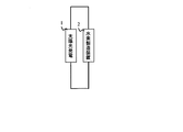
図1は、本発明の第1実施形態に係る水素製造手段を備えた太陽光発電システム構成を模式的に表す図である。図1において、実線は電気配線を、破線は切替信号出力線を、点線は信号計測線を、それぞれ表しており、各手段同士を接続する配線であって信号およびエネルギの授受を表している。
[1.第1実施形態]
図1は、本発明の第1実施形態に係る水素製造手段を備えた太陽光発電システム構成を模式的に表す図である。図1において、実線は電気配線を、破線は切替信号出力線を、点線は信号計測線を、それぞれ表しており、各手段同士を接続する配線であって信号およびエネルギの授受を表している。
図1に示すように、第1実施形態に係る水素製造手段を備えた太陽光発電システム100は、高効率で太陽光エネルギを利用、貯蔵、供給可能とするものである。そして、水素製造手段を備えた太陽光発電システム100は、再生可能エネルギ発電手段としての太陽光発電装置1と、水素製造手段としての水素製造装置2と、太陽光発電電力の最適直流電力を交流電力に変換する電力変換制御器3と、水素製造装置2及び電力変換制御器3の電気的な接続構成を切替えるための切替手段4と、太陽光発電装置1から出力される出力電力W1および電力変換制御器3から出力される出力電力W2を検出する電力検出手段(電力検出器11,12)と、システム全体を制御する制御部6とを少なくとも備えて構成されている。本実施形態の太陽発電システムでは、太陽光発電装置1の定格出力電力を電力変換制御器3の定格出力電力よりも大きくしている。これにより、太陽光発電装置1と電力変換制御器3の定格出力電力を同等の出力仕様とした場合と比較して日射強度の低い条件下における電力変換制御器3の変換効率の向上を図っている。
再生可能エネルギである太陽光エネルギは、太陽光発電装置1との電気的若しくは物理的な接続線、配管等は存在せず、地球気象条件に基づくものである。
太陽光発電装置1は太陽光エネルギを直流電力に変換する装置であり、水素製造装置2と、電力変換制御器3と電気的に接続され、切替手段4によって電気的な接続構成が切替えられる。太陽光発電装置1で発電した電力は、電力変換制御器3を介して系統に供給される。また、切替手段4によって太陽光発電装置1と水素製造装置2を接続することにより、太陽光発電装置1で発電した電力を水素製造装置2に供給して、水素製造装置2で電力を水素エネルギに変換することで電力を化学エネルギとして貯蔵、供給される。
水素製造装置2は、太陽光発電装置1によって得られた電力を用いて水素を製造するものである。具体的には、水素製造装置2においては、これらの電力を用いて電解液を電気分解することにより、少なくとも水素が発生するようになっている。従って、太陽光発電装置1から水素製造装置2に供給される電力が多ければ多いほど、水素製造装置2において製造される水素の量も多くなる。水素製造装置2は、太陽光発電装置1と切替手段4を介して電気的に接続されている。
水素製造装置2の具体的な構成は特に制限されないが、水素製造装置2は、例えば、電解液と、電解質と、当該電解質を挟むように設けられた反応促進用の電極触媒と、外部電力を供給する集電体等を保持した電気分解セルを有している。そして、この電極触媒により水が電気分解され、水素及び酸素が発生するようになっている。本発明では、前記電気分解セルまたは、電気分解セルを多層積層した電気分解スタックを水素製造装置2と定義している。複数個の電気分解スタックを電気的な接続構成が切替え可能なように接続して水素製造装置2が構成される。
前記の電解液としては、電気分解することにより少なくとも水素が発生するものであれば特に制限は無いが、例えば水酸化カリウム等の、水に溶解させたときにアルカリ性を示す化合物が好ましい。このような化合物を用いることにより、安価かつ腐食しにくい水素製造装置2とすることができる。また、電解質としては、例えばイオン導電性の固体高分子型電解質を用いることもできる。
このように構成した水素製造装置2は、低温での運転が可能であり、さらには、短時間で起動可能な利点を有する。
水の電気分解条件は特に制限されず、少なくとも水素を発生させることができれば任意の条件にすることができる。ただし、電解効率を高めるために、電気分解時の温度を高める場合、温度制御アルゴリズムを考慮しなければならない。
電力変換制御器3は、主に昇圧回路やインバータ回路など電力変換回路に加え、太陽電池から電力を効率よく変換するために、最大電力追従制御と呼ばれるMPPT(Maximum Power Point Tracking)制御により高い出力電力が得られる機能を有するものである。MPPT制御方式は特に限定されず、太陽電池の発電する最大電力をパワーコンディショナにて交流電力に変換し、系統連系して電力を外部供給できるシステムであれば良い。
切替手段4は、制御信号出力部8の指令を受けて、電気的に遮断、導通できる機能を有していればよく、部品材料、構成は特に限定されない。例えば機械的接点スイッチや、リレー、半導体スイッチ素子等を自由に選択できる。ただし、電気的な仕様は、設計段階で整合をとる必要があり、システム規模に応じて適合する切替手段を選択できる。
切替手段4で切替えられる接続構成の一例を図3に示す。図3Aの構成(1)は、図1のスイッチ4a、4c、4dを遮断、スイッチ4bを導通させて、太陽光発電装置1に電力変換制御3のみを電気的に接続した構成である。図3Bの構成(2)は、図1のスイッチ4b、4cを遮断、スイッチ4a、4dを導通させて、太陽光発電装置1に水素製造装置2と電力変換制御3を直列に接続した構成である。図3Cの構成(3)は、図1のスイッチ4dを遮断、スイッチ4a、4b、4cを導通させて、太陽光発電装置1に水素製造装置2と電力変換制御3を並列に接続した構成である。図3Dの構成(4)は、図1のスイッチ4b、4dを遮断、スイッチ4a、4cを導通させて、太陽光発電装置1に水素製造装置2のみを電気的に接続した構成である。
制御部6は、各計測信号を処理する信号処理部7と、切替手段4に制御信号を出力する制御信号出力部8と、信号演算部9と、を備える。信号演算部9では、太陽光アレイ出力の電圧、電流から推定されるパネル温度及び日射強度の推定量から太陽光発電装置の発電予測電力W0の算出等の演算が行われる。
<動作>
次に、本実施形態の水素製造手段を備えた太陽光発電システム100において、水素製造装置と電力変換制御器の接続を切替える切替手段4の動作を図1~図7を参照しながら説明する。
<動作>
次に、本実施形態の水素製造手段を備えた太陽光発電システム100において、水素製造装置と電力変換制御器の接続を切替える切替手段4の動作を図1~図7を参照しながら説明する。
はじめに、太陽光エネルギを利用し、太陽光発電装置1が直流電力を発電する。発電された直流電力は、電力変換制御器3を介して交流電力に変換されて系統に供給される。
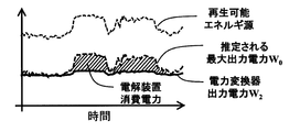
図2に示すように、再生可能エネルギ源である太陽光エネルギの日射強度の時間変化に対応して太陽光発電装置1の発電予測電力W0が変動する。太陽光発電装置1の最大出力電力が電力変換制御器3の定格出力電力よりも高い場合には、太陽光発電装置1の発電予測電力W0が電力変換制御器3の定格出力電力を上回る場合がある。太陽光発電装置1に電力変換制御器3のみが接続されている場合には、太陽光発電装置1では電力変換制御器3の定格出力電力を上回る電力は発電されないため、太陽光エネルギを十分に利用できないことになる。そこで、本実施形態の太陽光発電システムでは、太陽光発電装置1の発電予測電力W0が電力変換制御器3の出力電力W2を上回る際には、図3Bの構成(2)または図3Cの構成(3)に示すように太陽光発電装置に対して水素製造装置2と電力変換制御器3の接続構成が直列及び/または並列接続になるように切替手段4で接続構成を切替える。このように接続構成を切替えることで、電力変換制御器3の定格出力電力を上回る余剰電力が水素製造装置2に供給され、電気分解が開始して水素が発生する。このとき、電力変換制御器3の出力電力W2は水素製造装置2の接続に影響されず出力を維持することが求められる。
図3Aの構成(1)を基本構成として系統連係を優先する場合、システム運転は例えば図4に図示する制御フローチャートに基づいてシステム制御を行うことができる。STEP1を開始地点とすれば、STEP2において電力変換制御器3の変換効率が所定の値以上であるかの判断を行う。例えば電力変換効率の所定の値を95%と設定すると、太陽光発電装置1による出力電力W1と電力変換制御器3の出力電力W2から、変換効率を算出し、算出結果が定めた数値95%以上であるか比較し、判断する。
STEP3はSTEP2の判断が否の場合に生じる判断フローである。この際、変換効率が所定値を満たしていない要因として、再生可能エネルギ源である推定日射強度の低下が挙げられる。電力変換制御器3は、図5に示されるように、電力変換制御器3の出力電力によって電力変換効率が変化する特性を有する。これは、電力変換制御器3の出力電力に対して、電力変換器の消費電力の割合変化や、内部抵抗による損失量の割合が変わるためである。これにより低出力域は変換効率が著しく低く、高出力域では最大効率よりも低値になりやすい。このため、STEP3では推定される日射強度が低出力域に該当するかを判断する。ここでSTEP3の日射強度が低出力域か否かの判断に用いる日射強度の基準値として200[W/m2]とした例を挙げたが、これは図5に図示するように出力と電力変換効率によって変わり、この限りでは無い。低出力域に該当するか否の判断基準としては以下が挙げられる。低出力域においては、図5に図示する点A1、点B、点C等を境に、電力変換制御器変換効率よりも化学燃料貯蔵の変換効率の方が高効率となる領域が存在する。ここで、点A1は水素製造装置2で電力を水素に変換する変換効率と同等になる点である。点Bは水素製造装置2で製造された水素を燃料として発電手段を用いて発電した場合の電力供給効率と同等になる点である。点Cは水素製造装置2で製造された水素を後述する有機ハイドライドの形態で貯蔵し、有機ハイドライドから水素を取り出して発電手段を用いて発電した場合の電力供給効率と同等になる点である。なお、点B、Cの電力供給効率は、太陽光発電装置1で発電された電力エネルギに対して、最終的に上記発電手段で系統あるいはその他の負荷に供給できる電力エネルギの供給効率である。
STEP4は、STEP3において推定日射強度が弱く低出力域に該当すると判断された場合に実行される処理であり、図3Dの構成(4)の接続形態となるように制御部6の制御信号出力部8から切替手段4に制御指令値が出される。このような、化学燃料貯蔵の変換効率あるいは化学燃料貯蔵を利用した発電手段の発電供給効率の値を基準として、電力変換制御器3を介した系統への電力供給から、構成(4)の水素製造手段2を用いた化学燃料貯蔵に切替えることで、太陽光エネルギを効率よく有効に利用することが可能となる。その後、STEP12において低照度が続く限りは構成(4)を維持する処理がなされ、照度が向上された場合は、構成(1)に戻る。
STEP5は、STEP3において高出力域に該当すると判断された場合に実行される処理であるが、電力変換効率が95%を下回り、かつ推定日射強度が高い場合は、電力変換制御器3や周辺機器に劣化などの異常を生じている場合がある。STEP5では、異常の可能性があること示すためのエラー信号を制御部6から出力する。
次に、STEP6は、STEP2において、太陽光発電装置1による出力電力W1と電力変換制御器3の出力電力W2との除算で算出される電力変換効率が95%以上である場合に実行される処理である。ここでは、太陽光発電装置1による出力電力W1の電圧値、電流値及び初期太陽光発電装置の定格出力電力から、計測時点の日射強度及びパネル温度を信号演算処理部9にて演算する。また、信号演算処理部9において、算出された推定日射強度またはパネル温度から推定される太陽発電装置1で発電可能な最大の発電予測電力W0が演算される。なお、発電予測電力W0の予測する算出方法はこれに限定されるものではなく、公知の手法を適用することができる。STEP6では、太陽光発電装置1の発電予測電力W0と電力変換制御器3の出力電力W2の関係から余剰電力があるかどうかの判断を行う。図4の例では、W2/W0が0.95以上(すなわち95%以上)であるかを確認し、該当する場合は構成(1)を維持するようにしている。なお、発電予測電力W0と実際の太陽光発電装置1の出力電力W1の関係(W1/W0)で判断してもよい。
STEP7は、STEP6が否の場合に実行される処理である。この場合、電力変換効率は95%以上であるが、発電予測電力W0が実出力電力を上回りエネルギ余剰状態にある。従って水素製造装置2を接続することで、余剰エネルギ回収が可能となり、エネルギ回収効率を高めることができる。水素製造装置2は、本処理において直列接続か並列接続を選択できる。なお、水素製造装置2は複数の電気分解スタックが電気的に接続された構成を備え、電気分解スタックの電気的な接続構成を切替える制御手段を備えている。
並列接続を選択する場合、STEP9処理を実行し、図3Cの構成(3)の接続構成をとる。この場合、電力変換制御器3の入力電圧値に適合する形で、稼動させる電気分解スタックの数を選択する必要がある。なお、電気分解スタックを構成するセル数を制御できるように構成した場合にはセル数の選択も可能である。例えば、水の電気分解において、分解が開始される電位は、一般的に1.47~1.48V/セルである。一方で、電力変換制御器3は製品により異なるがおおよそ数百Vであり、ここでは仮に300Vとする。すなわち電解セルは最大203~204セルの直列セル構造が必要であることが分かる。ただし、分解開始電位で設計したところで水素ガスは得られないため、実際にはこれより少ないセル数で設計する必要がある。水素製造装置2の特性は、電解液温度や電解槽内圧力などの環境や、配線抵抗、電解槽構成による抵抗成分、電解液成分等に起因する分解電位の変化量等を考慮し、単位セル当たりの駆動電解電位を演算する必要がある。最適セル数を演算し、水素製造装置2を構成する電気分解スタックの接続構成を制御する。
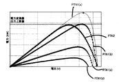
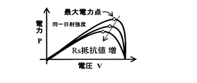
直列接続を選択する場合、STEP8の処理を実行し、図3Bの構成(2)の接続構成をとる。この場合、推定日射強度から推定される発電予測電流I0及び発電予測電圧V0、電力変換制御器3の出力電力W2に応じて電気分解スタック数及び/又はセル数を選択できる。例えば、図6に図示するPTN1(a)からPTN1(d)の太陽光発電特性のように、日射強度の変化に応じて太陽光発電特性は変化するが、発電予測電力W0が電力変換器の出力電力を上回る状況とは最大日射強度時における太陽光発電予測特性であるPTN1(a)の特性である。ここで、発電予測電力W0の電圧はV0、電流がI0であるので、水素製造装置2と電力変換制御器は直列接続構成の回路電流はI0となる。従って、電力変換制御器の出力電力W2を維持するためには、V21N=(W2/変換効率)/I0の入力電圧値が求められる。すなわち、水素製造装置の稼働電圧はV水素製造装置=(V0-V21N)により算出される。従って水素製造装置の単位セル当たりの電圧電流特性が予め既知であれば、稼働電流I0と稼働電圧V水素製造装置から必要セル数の概算値を求めることができ、構成切替制御を実施し直列接続構成をとる。なお、太陽電池に直列に水素製造装置すなわち負荷を接続するため、電力変換制御器に入力される見かけ上の太陽光発電特性はPTN1(a)から変化する。たとえば図7Aに図示するように、一般的に太陽電池の等価回路は電流源、ダイオードおよび並列抵抗成分の並列接続に対して、直列接続成分が直列に接続された構成となる。ここで直列抵抗成分が増大すると出力電力は低下傾向にあるが、図7Bおよび図7Cに示した太陽電池抵抗成分増加特性のように、電圧電流特性及び電圧電力特性ともに左下がりの方向に特性が変化する。すなわちPTN1(a)特性において水素製造装置すなわち負荷を直列接続した場合(構成2)、電力変換制御器に入力される見かけ上の太陽光特性は、PTN2のようになる。この際、電力変換制御器の出力の上限値と、入力電圧、入力電流範囲を満足する条件が必要になる。
次に、STEP10は、STEP8またはSTEP9の接続構成の切替え後も電力変換制御器の出力W2が維持されているか、変動割合を確認する処理である。ここでは、接続構成切替前の出力W2beforeに対して、接続構成切替後の出力W2afterが95%以上であればSTEP11に移行し、95%未満であれば構成(1)に切り替える処理及び設定値としている。ただし、設定数値はシステム運転上必要な数値で良く、この限りではない。たとえば接続構成の切替えによってW2が変動しても良く、水素製造を主体としたシステム運転を希望する場合には、設定数値を低くしてかまわない。
STEP11は、構成(1)に戻した方がエネルギ回収率が高いかを確認する処理である。ここでは、構成(1)において、本タイミングの発電予測電力W0にて予測される電力変換制御器W2出力値が、現在構成(すなわち構成(2)または構成(3))の電力変換制御器出力値W2より上回る場合は、構成(1)に戻した方が良く、そうでない場合は現在の接続構成を維持した方がエネルギ回収率としては高い。このような処理であれば、STEP11に記載する内容でなくてもかまわない。
以上、図4を用いて水素製造装置と電力変換制御器の接続切替手段について記載したが、これらはいずれも動作システム運用法に関するものであり、システム運用者のニーズに応じて変えることができ図4の限りではない。また図4に記載した数値についても同様で、運転方法に応じて変更して良い。また、数値は実運転上、許容誤差幅を持たせると好ましく、さらに切替後は一定時間構成を維持する機能など付与し、頻繁な構成切替を抑止する機能があると望ましい。
<まとめ>
以上のように、第1実施形態に係る水素製造手段を備えた太陽光発電システム100によれば、高効率で太陽光エネルギを利用、貯蔵、供給できる。
[2.第2実施形態]
図8は、本発明の第2実施形態に係る水素製造手段を備えた太陽光発電システム構成を模式的に表す図である。図8において、実線は電気配線を、破線は切替信号出力線を、点線は信号計測線を、二重線は燃料(気体、液体)を、それぞれ表しており、各手段同士を接続する配線及び配管であって、信号、エネルギ及び物質の授受を表している。
<まとめ>
以上のように、第1実施形態に係る水素製造手段を備えた太陽光発電システム100によれば、高効率で太陽光エネルギを利用、貯蔵、供給できる。
[2.第2実施形態]
図8は、本発明の第2実施形態に係る水素製造手段を備えた太陽光発電システム構成を模式的に表す図である。図8において、実線は電気配線を、破線は切替信号出力線を、点線は信号計測線を、二重線は燃料(気体、液体)を、それぞれ表しており、各手段同士を接続する配線及び配管であって、信号、エネルギ及び物質の授受を表している。
図8に示すように、第2実施形態に係る水素製造手段を備えた太陽光発電システム200は、高効率で太陽光エネルギを利用、貯蔵及び供給することを可能とするものである。図1に図示した水素製造手段を備えた太陽光発電システム100に対して、電解液を水素製造装置2に送液する送液ポンプ13と、電解液を蓄え且つ水素ガスと電解液に気液分離する電解液タンク15と、水素の高純度化を担うバッファタンク14と、不飽和炭化水素を貯蔵する不飽和炭化水素タンク16と、飽和炭化水素を貯蔵する飽和炭化水素タンク17と、水素ガスを不飽和炭化水素に付与して飽和炭化水素を得る水素添加手段18と、飽和炭化水素から不飽和炭化水素及び水素を分離する反応器19と、水素ガスを利用した電力供給手段である発電手段20と、飽和炭化水素供給手段21と、不飽和炭化水素供給手段22とをさらに付与した構成である。
以下、水素製造手段を備えた太陽光発電システム200の構成を成す背景を記述する。
太陽光発電電力は変動電力であるため、発電電力量(電力供給量)と電力需要量とは必ずしも一致しない。短期的に電力の需要量と供給量を一致させるためには、一度電力を蓄え、必要なときに取りだすキャパシタンスや二次電池等の応答性の優れる蓄電デバイス及び制御システムが必要となる。また、昼夜などの短中期的及び長期的に電力を安定供給するためには、前述の方法の大容量化に加えて、化学エネルギ変換による蓄エネルギ手法、すなわちエネルギ燃料化法がある。この中でも、化石燃料代替材料として注目されているのが水素エネルギである。
水素製造方法として、化石燃料の水蒸気改質が工業的に広く利用されている。また、このほかにも、鉄又はソーダ製造に伴う副生水素、熱分解、光触媒、微生物、水の電気分解を用いた反応等、多数の製造方法が知られている。中でも、水の電気分解に必要な電力としては様々の供給源からの電力を利用することが可能である。従って、水の電気分解による水素の製造方法は、特定の地域に依存しないエネルギ源の製造方法として重要視されている。
しかし、水素をエネルギ源(即ち燃料)として用いるためには、水素の輸送、貯蔵、供給システム等が大きな課題となりえる。具体的には、水素は常温常圧で気体であるため、液体及び固体に比べて、貯蔵及び輸送が困難であるという課題がある。さらに、水素は可燃性物質であり、空気と水素とが所定の混合比で混合されると、水素が爆発的に反応する可能性がある。
これらの課題を解決する技術として、近年、安全性、運搬性及び貯蔵能力に優れた水素貯蔵方法として、例えばシクロヘキサン、デカリン等の炭化水素を用いた有機ハイドライドシステムが注目されている。これらの炭化水素は常温常圧で液体であるため、気体の場合と比べて容易に貯蔵及び運搬できる。例えば、ベンゼン及びシクロヘキサンは同じ炭素数を有する環状炭化水素であるが、ベンゼンは二重結合を有する不飽和炭化水素であるのに対し、シクロヘキサンは二重結合を有さない飽和炭化水素である。即ち、不飽和炭化水素であるベンゼンに対して水素が付加されることにより、飽和炭化水素であるシクロヘキサンが得られる。また、シクロヘキサンから水素が脱離されることにより、ベンゼンが得られる。このように、ベンゼン及びシクロヘキサンを用いた水素付加反応と水素脱離反応とを利用し、水素の貯蔵と供給とが可能になるシステムが構築できる。
水素製造手段を備えた太陽光発電システム200は、本技術を応用するものであり、変動電力である太陽光発電電力を効率的に利用、貯蔵及び供給するために、電力変換制御器3及び水素製造装置2の切替制御を実施する。
以下、水素製造手段を備えた太陽光発電システム200の各構成説明及びシステム動作を合わせて記述する。
水素製造装置2は、太陽光発電装置1によって得られた電力を用いて水素を製造するものである。具体的には、水素製造装置2においては、これらの電力を用いて電解液を電気分解することにより、少なくとも水素が発生するようになっている。従って、太陽光発電装置1から水素製造装置2に供給される電力が多ければ多いほど、水素製造装置2において製造される水素の量も多くなる。水素製造装置2は、太陽光発電装置1と切替手段4を介して電気的に接続され、送液ポンプ13及び電解液タンク15と配管接続されている。
また、水素製造装置2は、複数の電解セルからなるセルスタックを複数有し、セルスタックが互いに電気的に直列又は並列に接続構成を選択できる切替機能を有することが好ましい。このような構成にすることで、電力制御変換器2の出力電力を維持しつつ、太陽光発電の変動電力分を水電解装置で吸収し、水素製造及び貯蔵に利用することができる。
また、水素ガスの高純度化および気液分離を担うバッファタンク14と、水素製造装置2に電解液を供給する送液ポンプ13と、循環液内気泡の気液分離を担う電解液タンク15と、水素添加手段18と、を少なくとも備えて構成してもよい。なお電解液を加温するための熱制御手段も備えてもよい。電解液タンク15の具体的な構成は特に制限されないが、水素製造装置2で製造した水素気泡成分と電解液の分離による水素高純度化が目的であり、バッファタンク14を介して水素添加手段18に供給される前に液体除去などによる手法が挙げられる。例えば気液分離装置などが、それに当たる。気液分離装置の具体的な構成としては特に制限されないが、例えば冷却による気液分離、水素分離膜等を用いることができ、中でも水素分離膜を用いることが好ましい。なお、除去された液体は水素製造装置2内を循環し、当該液体が電気分解されるようになっている。
そして、水分除去後の水素は、ガス配管によって接続されたバッファタンクを介して水素添加手段18に供給されるようになっている。なお、水分除去後の水素は直接水素添加手段18に供給されるようにしてもよいが、当該水素を圧力調整器を介して反応器に供給することで、水素添加効率を更に高めることができ、換言すると、再生可能エネルギを無駄なく貯蔵できる。
また、図8では図示していないが、当該水素を例えば高圧タンク等の水素貯蔵手段に一時的に貯蔵することもできる。水素貯蔵手段の具体的な構成は特に制限されるものではないが、例えば公知の水素ボンベ、高圧ガス用の圧力容器等を用いることができる。これらは1種を単独で設けてもよく、2種以上を任意に組み合わせて設けてもよい。水素貯蔵手段を構成する材料としては、例えば鋼板、カーボン繊維で強化されたプラスチック等が挙げられ、水素製造装置2にかかる圧力以上の耐圧容器を用いることが特に好ましい。
また、水素貯蔵手段としては、水素吸蔵合金を用いることもできる。水素吸蔵合金としては、例えば希土類金属-ニッケル系等のAB5型合金、チタン系、クロム系等の体心立方(BCC)構造を有する合金等が挙げられる。これらの水素吸蔵合金を上記の容器等内に存在させることにより、水素貯蔵量を増加させることができる。また、同一体積の水素を貯蔵する場合には、水素貯蔵手段の圧力を低下させてもよい。
バッファタンク14と水素添加手段18とはガス配管(パイプライン)によって接続されていることが好ましい。ただし、これらがガス配管によって接続されている必要は必ずしも無く、例えば高圧タンク等を用いて、製造した水素を水素添加手段18まで運搬(即ち水素添加手段18に供給)するようにしてもよい。
水素添加手段18は、水素製造装置2によって製造された水素を不飽和炭化水素に対して付加させるものである。水素添加手段18は、前記のようにバッファタンク14とガス配管によって接続されているほか、飽和炭化水素タンク17と液体配管され、さらに不飽和炭化水素供給手段22を介して不飽和炭化水素タンク16と液体配管によって接続されている。従って、不飽和炭化水素は不飽和炭化水素タンク16から供給手段22により水素添加手段18に供給される。
水素添加手段18において用いられる不飽和炭化水素の具体的な種類は特に制限されないが、例えばトルエン等の室温で液体の芳香族化合物を好適に用いることができる。例えば不飽和炭化水素としてトルエンを用いる場合、得られる飽和炭化水素はメチルシクロヘキサンである。ただし、付加反応時の条件によっては、例えばアントラセン、フェナントレン等も液体になることもあるため、そのような条件で付加反応を行う場合には、これらの芳香族化合物を用いてもよい。これらの芳香族化合物を用いることにより、よりさらに多くの水素を貯蔵することができる。
このような芳香族化合物は室温で液体であるため貯蔵が容易であり、また、水素付加反応を行わせるときの反応界面が大きくなる利点がある。また、芳香族化合物を用いることにより芳香族化合物1分子あたりに付加しうる水素の物質量を多くすることができ、より多くの水素を少ない不飽和炭化水素量で貯蔵することができる。なお、不飽和炭化水素は1種で用いてもよく、2種以上を任意の比率及び組み合わせで用いてもよい。
水素添加手段18において、不飽和炭化水素に対して水素を付加する具体的な方法に特に制限は無い。ただし、低コスト及び反応時間が短いという観点から、通常は触媒を用いて不飽和炭化水素に水素を付加させる。このような触媒としては、例えばNi、Pd、Pt、Rh、Ir、Re、Ru、Mo、W、V、Os、Cr、Co、Fe等の金属、及びこれらの合金が挙げられる。触媒を構成する金属及びそれらの合金は、1種が単独であってもよく、2種以上が任意の比率及び組み合わせで用いられてもよい。
また、これらの触媒は、触媒量の低減による更なる低コスト化と反応表面積の増大化の観点から、微粒子化されていることが好ましい。微粒子化された触媒を用いる場合、微粒子触媒の凝集による表面積の減少を防止する観点から、任意の担体に担持してもよい。担体に触媒を担持させる場合、担持させる方法に特に制限は無く、例えば、共沈法、熱分解法、無電解めっき法等を用いることができる。また、担体の種類も特に制限は無く、例えば活性炭、カーボンナノチューブ、黒鉛等の炭素材料のほか、シリカ、アルミナ、ゼオライト等のアルミナシリケート等を用いることもできる。担体は1種であってもよく、2種以上を任意の比率及び組み合わせで用いてもよい。
水素添加手段18における、不飽和炭化水素への水素付加反応条件は特に制限されず、任意に設定すればよい。例えば反応温度は室温(約25℃)でも水素を付加させることができるが、反応時間をより短くする観点から、100℃以上400℃以下程度の温度で付加させることが好ましい。
また、付加反応時の反応圧力も特に制限されないものの、付加反応効率を上げ、反応時間をより短くすることができるという観点から、水素付加時の圧力を、ゲージ圧で1気圧以上50気圧以下(即ち0.1MPa以上5MPa以下)とすることが好ましい。従って、図8には図示しないが水素付加時の圧力を高めるために、バッファタンク14と水素添加手段18との間には、圧力調整器を備えてもよい。
以上のようにして、不飽和炭化水素に水素を付加させることができ、飽和炭化水素が得られる。得られた飽和炭化水素(所謂有機ハイドライド)は、後記する飽和炭化水素タンク17に貯蔵される。
送液ポンプ13は電解液性質、水素製造装置への供給流量などにより仕様が決まるものであり、配管を介して電解液タンク15、水素製造装置2と接続されている。
飽和炭化水素タンクに貯蔵された飽和炭化水素は、反応器19にて水素と不飽和炭化水素タンクに分離される。
反応器19は、飽和炭化水素を水素と不飽和炭化水素に分離させるものであり、前記飽和炭化水素の供給手段21を介して飽和炭化水素タンク17及び不飽和炭化水素タンク16と液体配管によって接続されている。従って、飽和炭化水素は飽和炭化水素タンク17から供給手段21によって反応器19に供給される。
反応器19において用いられる不飽和炭化水素の具体的な種類は特に制限されないが、例えばトルエン等の室温で液体の芳香族化合物を好適に用いることができる。例えば不飽和炭化水素としてトルエンを用いる場合、得られる飽和炭化水素はメチルシクロヘキサンであるが、水素添加手段18にて取り扱う液体をリサイクル利用できる物質が好ましい。すなわち、反応器19は、水素添加手段18と同じ材料、構成でも良いし、異なる材料、構成でもよく、不飽和炭化水素と水素を分離する具体的な方法に特に制限は無い。ただし、低コスト及び反応時間が短いという観点から、通常は触媒を用いて不飽和炭化水素と水素を分離させる。このような触媒としては、例えばNi、Pd、Pt、Rh、Ir、Re、Ru、Mo、W、V、Os、Cr、Co、Fe等の金属、及びこれらの合金が挙げられる。触媒を構成する金属及びそれらの合金は、1種が単独であってもよく、2種以上が任意の比率及び組み合わせで用いられてもよい。
また、これらの触媒は、触媒量の低減による更なる低コスト化と反応表面積の増大化の観点から、微粒子化されていることが好ましい。微粒子化された触媒を用いる場合、微粒子触媒の凝集による表面積の減少を防止する観点から、任意の担体に担持してもよい。担体に触媒を担持させる場合、担持させる方法に特に制限は無く、例えば、共沈法、熱分解法、無電解めっき法等を用いることができる。また、担体の種類も特に制限は無く、例えば活性炭、カーボンナノチューブ、黒鉛等の炭素材料のほか、シリカ、アルミナ、ゼオライト等のアルミナシリケート等を用いることもできる。担体は1種であってもよく、2種以上を任意の比率及び組み合わせで用いてもよい。
反応器19における、不飽和炭化水素と水素の分離反応条件は特に制限されず、任意に設定すればよい。例えば反応温度は室温(約25℃)でも水素を分離させることができるが、高い圧力を要することや、反応時間をより短くする観点から、100℃以上500℃以下程度の温度で付加させることが好ましい。また、加温のための熱エネルギは地熱、太陽熱などの再生エネルギや、周辺機器から排出される熱エネルギ(排熱)を用いると、よりシステム効率が向上する。
また、分離反応時の反応圧力も特に制限されないものの、分離反応効率を上げ、反応時間をより短くすることができるという観点から、水素分離時の圧力を、ゲージ圧で1気圧以上50気圧以下(即ち0.1MPa以上5MPa以下)とすることが好ましい。従って、図8には図示しないが水素分離時の圧力を高めるために、圧力調整器を備えてもよい。
以上のようにして、不飽和炭化水素と水素を分離させることができ、不飽和炭化水素が得られ、不飽和炭化水素タンク16に回収され、再利用に用いることができる。
分離された水素は発電手段20に利用され電力供給に用いることができ、これによって系統負荷変動を緩和することができる。発電手段20は、水素燃焼エンジン発電機や、燃料電池などが挙げることができるが、水素ガスを用いて電力変換できるアプリケーションであれば良く、特に制限はない。
また、これら一連の動作が行われる環境は特に制限されず、前記課題を解決することができるのであれば任意の環境で行うことができる。また、全ての装置が同地域や箇所に設置される必要は必ずしも無く、例えば水素製造装置2は室内に、また、水素添加手段18は室外に、飽和炭化水素タンク17から飽和炭化水素のみ取出し運送し、別地域にて反応器19および発電手段20を介して電力供給することや,駆動動力燃料として利用することなど、任意に設置及び利用することができる。
以上のように、第2実施形態に係る水素製造手段を備えた太陽光発電システム200によれば、高効率で太陽光エネルギを利用、貯蔵及び供給できる。
[3.第3実施形態]
図9は、本発明の第3実施形態に係る水素製造手段を備えた太陽光発電システム構成を模式的に表す図である。図9において、実線は電気配線を、破線は切替信号出力線を、点線は信号計測線を、二重線は燃料(気体、液体)を、それぞれ表しており、各手段同士を接続する配線及び配管であって、信号、エネルギ及び物質の授受を表している。
[3.第3実施形態]
図9は、本発明の第3実施形態に係る水素製造手段を備えた太陽光発電システム構成を模式的に表す図である。図9において、実線は電気配線を、破線は切替信号出力線を、点線は信号計測線を、二重線は燃料(気体、液体)を、それぞれ表しており、各手段同士を接続する配線及び配管であって、信号、エネルギ及び物質の授受を表している。
図9に示すように、第3実施形態に係る水素製造手段を備えた太陽光発電システム300は、高効率で太陽光エネルギを電力供給及び貯蔵、供給可能とするものである。図1に図示した水素製造手段を備えた太陽光発電システム100に対して、太陽光発電量を予測するためのデータ源となるパネル温度検出部5a及び日射強度検出部5bを備えた太陽光発電量予測源検出部5と、電解液を水素製造装置に送液する送液ポンプ13と、電解液を蓄え且つ水素ガスと電解液に気液分離する電解液タンク15と、水素の高純度化を担うバッファタンク14と、水素ガスを利用した電力供給手段である発電手段20と、を新たに付与した構成であり、少なくてもこれらを備えている。そして、このような構成を有する水素製造手段を備えた太陽光発電システム300が、再生可能エネルギに対して適用されるようになっている。
太陽光発電量予測源検出部5は、太陽光パネル温度及び日射強度検出部を備えており、通常これらのデータがあれば、発電予測電力W0を推定できる。パネル温度検出方法は熱電対、日射強度は全天型日射強度計等を用いて測定することができる。ただし、検出方法は、使用環境に応じて決めればよく、限定されるものではない。
また、バッファタンク14から放出される水素ガスを用いて発電手段20により発電することができる。この際、バッファタンク14に圧力弁等を用いて発電手段に対する水素ガス供給量を制御できる機能を有すると好ましい。このような構成とすることで、発電電力が制御できる。
以上のように、第3実施形態に係る水素製造手段を備えた太陽光発電システム300によれば、高効率で太陽光エネルギを利用、貯蔵、供給できる。
1 太陽光発電装置
2 水素製造装置
3 電力変換制御器
4 切替手段
5 太陽光発電量予測源検出部
6 制御部
7 信号処理部
8 制御信号出力部
9 信号演算部
11 電力検出器
12 電力検出器
13 送液ポンプ
14 バッファタンク
15 電解液タンク
16 不飽和炭化水素タンク
17 飽和炭化水素タンク
18 水素添加手段
19 反応器
20 発電手段
21 不飽和炭化水素供給手段
22 飽和炭化水素供給手段
2 水素製造装置
3 電力変換制御器
4 切替手段
5 太陽光発電量予測源検出部
6 制御部
7 信号処理部
8 制御信号出力部
9 信号演算部
11 電力検出器
12 電力検出器
13 送液ポンプ
14 バッファタンク
15 電解液タンク
16 不飽和炭化水素タンク
17 飽和炭化水素タンク
18 水素添加手段
19 反応器
20 発電手段
21 不飽和炭化水素供給手段
22 飽和炭化水素供給手段
Claims (14)
- 太陽エネルギを貯蔵する水素製造手段を備えた太陽光発電システムであって、
前記太陽光エネルギを直流電力に変換する太陽光発電装置と、
前記太陽光発電装置により得られる直流電力を交流電力に変換し且つ最大電力を得るための出力制御機能を有する電力変換制御器と、
前記太陽光発電装置により得られる直流電力を用いて水素を製造する水素製造手段と、
前記太陽光発電装置の出力電力W1および前記電力変換制御器の出力電力W2を検出する電力検出手段と、
前記太陽光発電装置と前記電力変換制御器および前記水素製造手段の電気的な接続構成を切替える切替手段と、
前記切替手段に制御信号を伝達する制御部と、を備え、
前記太陽光発電装置の定格出力電力は、前記電力変換制御器の定格出力電力よりも大きくなるように設定されており、
前記制御部は、前記太陽光発電装置で発電可能な発電予測電力W0を算出する電力予測手段を備え、
前記電力予測手段で推定した発電予測電力W0と前記電力検出手段で検出された出力電力W1または出力電力W2との比較結果、及び、前記電力変換制御器の変換効率特性に応じて、前記切替手段を制御することを特徴とする太陽光発電システム。 - 請求項1に記載の太陽光発電システムにおいて、
前記制御部は、前記電力検出手段で検出された出力電力W1と出力電力W2から前記電力変換制御器の変換効率を演算し、
前記電力変換制御器の変換効率が所定の値以上の場合には、前記太陽光発電装置に前記電力変換制御器、または前記電力変換制御器および前記水素製造手段の両方を接続し、
前記電力変換制御器の変換効率が所定の値よりも低い場合には、前記太陽光発電装置に前記水素製造手段を接続することを特徴とする太陽光発電システム。 - 請求項2に記載の太陽光発電システムにおいて、
前記制御部は、前記電力予測手段で推定した発電予測電力W0と前記電力検出手段で検出された出力電力W1または出力電力W2との比較し、出力電力W1または出力電力W2よりも発電予測電力W0が大きい場合に、前記太陽光発電装置に前記電力変換制御器および前記水素製造手段の両方を接続することを特徴とする太陽光発電システム。 - 請求項1に記載の太陽光発電システムにおいて、
前記電力予測手段は、前記電力検出手段で検出された出力電力W1と前記太陽光発電装置の定格出力電力から算出した日射強度または前記太陽光発電装置のパネル温度に基づいて、発電予測電力W0を算出することを特徴とする太陽光発電システム。 - 請求項1に記載の太陽光発電システムにおいて、
前記太陽光発電装置のパネル温度を検出する温度検出手段、または、日射強度を検出する日射強度検出手段の少なくとも一方を備え、
前記電力予測手段は、前記温度検出手段または前記日射強度検出手段で検出した情報に基づいて、発電予測電力W0を算出することを特徴とする太陽光発電システム。 - 請求項1に記載の太陽光発電システムにおいて、
前記水素製造手段は、水を電気分解して水素と酸素を発生する電気分解装置であることを特徴とする太陽光発電システム。 - 請求項2に記載の太陽光発電システムにおいて、
前記電力変換制御器の変換効率の所定の値は、前記水素製造手段で電力を水素に変換する変換効率に基づいて設定されることを特徴とする太陽光発電システム。 - 請求項2に記載の太陽光発電システムにおいて、
前記水素製造手段で製造された水素を燃料として発電する発電手段を備えることを特徴とする太陽光発電システム。 - 請求項2に記載の太陽光発電システムにおいて、
前記水素製造手段で製造された水素を不飽和炭化水素に対して付加させ、飽和炭化水素に変換して貯蔵する水素貯蔵手段を備えることを特徴とする太陽光発電システム。 - 請求項9に記載の太陽光発電システムにおいて、
前記水素貯蔵手段に貯蔵された飽和炭化水素の脱水素反応によって水素を生成する反応器を備えることを特徴とする太陽光発電システム。 - 請求項10に記載の太陽光発電システムにおいて、
前記反応器で生成した水素を燃料として発電する発電手段を備えることを特徴とする太陽光発電システム。 - 請求項8に記載の太陽光発電システムにおいて、
前記電力変換制御器の変換効率の所定の値は、前記水素製造手段を介して前記発電手段で発電した場合の電力供給効率に基づいて設定されることを特徴とする太陽光発電システム。 - 請求項2に記載の太陽光発電システムにおいて、
前記水素製造手段は、複数の電気分解装置が電気的に接続されて構成され、前記複数の電気分解装置の電気的な接続構成および稼動数を切替えるための制御手段を備えていることを特徴とする太陽光発電システム。 - 請求項13に記載の太陽光発電システムにおいて、
前記電力変換制御器の入力電力仕様及び変換効率に応じて、前記複数の電気分解装置の接続構成および稼動数を切替えることを特徴とする太陽光発電システム。
Priority Applications (1)
| Application Number | Priority Date | Filing Date | Title |
|---|---|---|---|
| EP14778911.9A EP2983056A4 (en) | 2013-04-05 | 2014-03-31 | SOLAR SYSTEM FOR PHOTOVOLTAIC ELECTRICITY GENERATION WITH HYDROGEN-PRODUCING AGENTS |
Applications Claiming Priority (2)
| Application Number | Priority Date | Filing Date | Title |
|---|---|---|---|
| JP2013-079099 | 2013-04-05 | ||
| JP2013079099A JP6257911B2 (ja) | 2013-04-05 | 2013-04-05 | 水素製造手段を備えた太陽光発電システム |
Publications (1)
| Publication Number | Publication Date |
|---|---|
| WO2014163044A1 true WO2014163044A1 (ja) | 2014-10-09 |
Family
ID=51658340
Family Applications (1)
| Application Number | Title | Priority Date | Filing Date |
|---|---|---|---|
| PCT/JP2014/059471 Ceased WO2014163044A1 (ja) | 2013-04-05 | 2014-03-31 | 水素製造手段を備えた太陽光発電システム |
Country Status (3)
| Country | Link |
|---|---|
| EP (1) | EP2983056A4 (ja) |
| JP (1) | JP6257911B2 (ja) |
| WO (1) | WO2014163044A1 (ja) |
Cited By (10)
| Publication number | Priority date | Publication date | Assignee | Title |
|---|---|---|---|---|
| CN105391400A (zh) * | 2015-11-19 | 2016-03-09 | 许继集团有限公司 | 一种光伏阵列运行状态预测方法 |
| JP2018165392A (ja) * | 2017-03-28 | 2018-10-25 | 東京瓦斯株式会社 | 水電解システム |
| CN112994075A (zh) * | 2019-12-13 | 2021-06-18 | 阳光电源股份有限公司 | 一种光伏离网制氢方法和系统 |
| CN113122879A (zh) * | 2021-04-16 | 2021-07-16 | 阳光新能源开发有限公司 | 一种制氢控制方法及制氢系统 |
| WO2022026760A1 (en) * | 2020-07-29 | 2022-02-03 | Nextracker Inc. | Fixed dc bus and hydrogen generation system |
| CN114134512A (zh) * | 2020-08-17 | 2022-03-04 | 国家能源投资集团有限责任公司 | 清洁能源发电制氢的控制方法、系统和存储介质 |
| CN114693105A (zh) * | 2022-03-25 | 2022-07-01 | 国核自仪系统工程有限公司 | 太阳能制氢装置性能的评估方法、系统、设备及存储介质 |
| CN116657191A (zh) * | 2023-07-24 | 2023-08-29 | 长江三峡集团实业发展(北京)有限公司 | 一种光伏制氢系统的容量配置方法、装置、介质、设备 |
| CN118523371A (zh) * | 2024-05-21 | 2024-08-20 | 康明斯氢能(上海)有限公司 | 电解水制氢系统的控制方法、装置、介质及系统 |
| CN119209724A (zh) * | 2024-11-20 | 2024-12-27 | 中建科工集团有限公司 | 家用式绿电与热电联供一体化系统及其能源智能控制方法 |
Families Citing this family (19)
| Publication number | Priority date | Publication date | Assignee | Title |
|---|---|---|---|---|
| JP6150142B2 (ja) | 2015-02-19 | 2017-06-21 | 国立大学法人岐阜大学 | エネルギー貯蔵輸送方法およびエネルギーキャリアシステム |
| US20180290887A1 (en) * | 2015-05-19 | 2018-10-11 | The Royal Institution For The Advancement Of Learning/Mcgill University | Solar energy harvesting and reversible hydrogen storage methods and systems |
| US12276420B2 (en) | 2016-02-03 | 2025-04-15 | Strong Force Iot Portfolio 2016, Llc | Industrial internet of things smart heating systems and methods that produce and use hydrogen fuel |
| WO2017136489A1 (en) * | 2016-02-03 | 2017-08-10 | Caspo, Llc | Smart cooking system that produces and uses hydrogen fuel |
| US10983507B2 (en) | 2016-05-09 | 2021-04-20 | Strong Force Iot Portfolio 2016, Llc | Method for data collection and frequency analysis with self-organization functionality |
| US11327475B2 (en) | 2016-05-09 | 2022-05-10 | Strong Force Iot Portfolio 2016, Llc | Methods and systems for intelligent collection and analysis of vehicle data |
| US11366455B2 (en) | 2016-05-09 | 2022-06-21 | Strong Force Iot Portfolio 2016, Llc | Methods and systems for optimization of data collection and storage using 3rd party data from a data marketplace in an industrial internet of things environment |
| CN114625077B (zh) | 2016-05-09 | 2024-12-17 | 强力物联网投资组合2016有限公司 | 用于工业物联网的方法和系统 |
| US11774944B2 (en) | 2016-05-09 | 2023-10-03 | Strong Force Iot Portfolio 2016, Llc | Methods and systems for the industrial internet of things |
| US11237546B2 (en) | 2016-06-15 | 2022-02-01 | Strong Force loT Portfolio 2016, LLC | Method and system of modifying a data collection trajectory for vehicles |
| US10908602B2 (en) | 2017-08-02 | 2021-02-02 | Strong Force Iot Portfolio 2016, Llc | Systems and methods for network-sensitive data collection |
| CA3072045A1 (en) | 2017-08-02 | 2019-02-07 | Strong Force Iot Portfolio 2016, Llc | Methods and systems for detection in an industrial internet of things data collection environment with large data sets |
| US20200133254A1 (en) | 2018-05-07 | 2020-04-30 | Strong Force Iot Portfolio 2016, Llc | Methods and systems for data collection, learning, and streaming of machine signals for part identification and operating characteristics determination using the industrial internet of things |
| EP4440165B1 (en) | 2019-01-13 | 2026-02-18 | Strong Force Iot Portfolio 2016, LLC | Monitoring and managing industrial settings |
| JP2022129264A (ja) * | 2021-02-24 | 2022-09-05 | 株式会社日立製作所 | エネルギー管理装置およびエネルギー管理方法 |
| JP2024538162A (ja) * | 2021-10-13 | 2024-10-18 | ディーユージー・テクノロジー・(オーストラリア)・ピーティーワイ・リミテッド | モジュール式電解セル配置のための方法と制御システム |
| CN114381759B (zh) * | 2022-02-11 | 2023-09-29 | 中国华能集团清洁能源技术研究院有限公司 | 一种光伏制氢系统的控制系统及控制方法 |
| JP7749512B2 (ja) * | 2022-05-23 | 2025-10-06 | 株式会社日立製作所 | 再生可能エネルギーの電力供給を管理する水電解システム |
| EP4672127A1 (en) | 2023-02-21 | 2025-12-31 | ENEOS Corporation | CONTROL DEVICE, HYDROGEN CARRIER MANUFACTURING SYSTEM AND CONTROL METHOD |
Citations (7)
| Publication number | Priority date | Publication date | Assignee | Title |
|---|---|---|---|---|
| JPH1153042A (ja) * | 1997-07-31 | 1999-02-26 | Matsushita Electric Works Ltd | 太陽光発電インバータ装置 |
| JP2005235082A (ja) | 2004-02-23 | 2005-09-02 | Matsushita Electric Works Ltd | 最大電力追尾制御方法及び電力変換装置 |
| JP2007019341A (ja) * | 2005-07-08 | 2007-01-25 | Toyota Motor Corp | 発電装置 |
| JP2007295718A (ja) * | 2006-04-25 | 2007-11-08 | Sharp Corp | 電力供給システム |
| JP2007330057A (ja) * | 2006-06-08 | 2007-12-20 | Kawasaki Plant Systems Ltd | 二次電池付太陽光システムの充電制御方法 |
| JP2008300745A (ja) | 2007-06-01 | 2008-12-11 | Nippon Oil Corp | 太陽光発電用パワーコンディショナ、太陽光発電システム及び太陽光発電システムの出力電力制御方法 |
| JP2010098792A (ja) | 2008-10-14 | 2010-04-30 | Ntt Facilities Inc | 電力変換システム、電力変換制御装置、電力変換制御方法及びプログラム |
Family Cites Families (4)
| Publication number | Priority date | Publication date | Assignee | Title |
|---|---|---|---|---|
| JP2004120903A (ja) * | 2002-09-26 | 2004-04-15 | Sharp Corp | 電力供給装置 |
| JP5294934B2 (ja) * | 2009-03-13 | 2013-09-18 | 日立コンピュータ機器株式会社 | 燃料電池発電システムとそのメンテナンス発電制御方法 |
| US8525369B2 (en) * | 2010-06-02 | 2013-09-03 | GM Global Technology Operations LLC | Method and device for optimizing the use of solar electrical power |
| JP5653452B2 (ja) * | 2010-12-03 | 2015-01-14 | 株式会社日立製作所 | 自然エネルギ貯蔵システム |
-
2013
- 2013-04-05 JP JP2013079099A patent/JP6257911B2/ja active Active
-
2014
- 2014-03-31 WO PCT/JP2014/059471 patent/WO2014163044A1/ja not_active Ceased
- 2014-03-31 EP EP14778911.9A patent/EP2983056A4/en not_active Withdrawn
Patent Citations (7)
| Publication number | Priority date | Publication date | Assignee | Title |
|---|---|---|---|---|
| JPH1153042A (ja) * | 1997-07-31 | 1999-02-26 | Matsushita Electric Works Ltd | 太陽光発電インバータ装置 |
| JP2005235082A (ja) | 2004-02-23 | 2005-09-02 | Matsushita Electric Works Ltd | 最大電力追尾制御方法及び電力変換装置 |
| JP2007019341A (ja) * | 2005-07-08 | 2007-01-25 | Toyota Motor Corp | 発電装置 |
| JP2007295718A (ja) * | 2006-04-25 | 2007-11-08 | Sharp Corp | 電力供給システム |
| JP2007330057A (ja) * | 2006-06-08 | 2007-12-20 | Kawasaki Plant Systems Ltd | 二次電池付太陽光システムの充電制御方法 |
| JP2008300745A (ja) | 2007-06-01 | 2008-12-11 | Nippon Oil Corp | 太陽光発電用パワーコンディショナ、太陽光発電システム及び太陽光発電システムの出力電力制御方法 |
| JP2010098792A (ja) | 2008-10-14 | 2010-04-30 | Ntt Facilities Inc | 電力変換システム、電力変換制御装置、電力変換制御方法及びプログラム |
Non-Patent Citations (1)
| Title |
|---|
| See also references of EP2983056A4 |
Cited By (15)
| Publication number | Priority date | Publication date | Assignee | Title |
|---|---|---|---|---|
| CN105391400B (zh) * | 2015-11-19 | 2019-05-21 | 许继集团有限公司 | 一种光伏阵列运行状态预测方法 |
| CN105391400A (zh) * | 2015-11-19 | 2016-03-09 | 许继集团有限公司 | 一种光伏阵列运行状态预测方法 |
| JP2018165392A (ja) * | 2017-03-28 | 2018-10-25 | 東京瓦斯株式会社 | 水電解システム |
| CN112994075B (zh) * | 2019-12-13 | 2024-05-14 | 阳光电源股份有限公司 | 一种光伏离网制氢方法和系统 |
| CN112994075A (zh) * | 2019-12-13 | 2021-06-18 | 阳光电源股份有限公司 | 一种光伏离网制氢方法和系统 |
| US12224703B2 (en) | 2020-07-29 | 2025-02-11 | Nextracker Llc | Fixed DC bus and hydrogen generation system |
| WO2022026760A1 (en) * | 2020-07-29 | 2022-02-03 | Nextracker Inc. | Fixed dc bus and hydrogen generation system |
| AU2021315664B2 (en) * | 2020-07-29 | 2024-11-07 | Nextpower Llc | Fixed DC bus and hydrogen generation system |
| CN114134512A (zh) * | 2020-08-17 | 2022-03-04 | 国家能源投资集团有限责任公司 | 清洁能源发电制氢的控制方法、系统和存储介质 |
| CN114134512B (zh) * | 2020-08-17 | 2023-03-07 | 国家能源投资集团有限责任公司 | 清洁能源发电制氢的控制方法、系统和存储介质 |
| CN113122879A (zh) * | 2021-04-16 | 2021-07-16 | 阳光新能源开发有限公司 | 一种制氢控制方法及制氢系统 |
| CN114693105A (zh) * | 2022-03-25 | 2022-07-01 | 国核自仪系统工程有限公司 | 太阳能制氢装置性能的评估方法、系统、设备及存储介质 |
| CN116657191A (zh) * | 2023-07-24 | 2023-08-29 | 长江三峡集团实业发展(北京)有限公司 | 一种光伏制氢系统的容量配置方法、装置、介质、设备 |
| CN118523371A (zh) * | 2024-05-21 | 2024-08-20 | 康明斯氢能(上海)有限公司 | 电解水制氢系统的控制方法、装置、介质及系统 |
| CN119209724A (zh) * | 2024-11-20 | 2024-12-27 | 中建科工集团有限公司 | 家用式绿电与热电联供一体化系统及其能源智能控制方法 |
Also Published As
| Publication number | Publication date |
|---|---|
| EP2983056A4 (en) | 2016-12-07 |
| JP2014203274A (ja) | 2014-10-27 |
| EP2983056A1 (en) | 2016-02-10 |
| JP6257911B2 (ja) | 2018-01-10 |
Similar Documents
| Publication | Publication Date | Title |
|---|---|---|
| JP6257911B2 (ja) | 水素製造手段を備えた太陽光発電システム | |
| JP5653452B2 (ja) | 自然エネルギ貯蔵システム | |
| JP5618952B2 (ja) | 再生可能エネルギ貯蔵システム | |
| JP5837081B2 (ja) | 水素製造システム | |
| EP2905359B1 (en) | Renewable energy storage system | |
| Abdin et al. | A review of renewable hydrogen hybrid energy systems towards a sustainable energy value chain | |
| CN109216729B (zh) | 供氢系统 | |
| Mittelsteadt et al. | PEM electrolyzers and PEM regenerative fuel cells industrial view | |
| CN112886040A (zh) | 一种利用有机液体储氢储能发电系统 | |
| JP5548032B2 (ja) | 有機ハイドライド脱水素システム | |
| Wilson et al. | Hydrogen production using solar energy | |
| JP5982253B2 (ja) | コージェネレーションシステム | |
| JP2025126195A (ja) | 水素生成システム、及び水素燃料利用システム | |
| Youssef et al. | Recent advances in hydrogen production technologies: environmental and economic perspectives | |
| Wei et al. | Evaluation on the efficiency of a solar powered solid oxide electrolysis cell plant for carbon dioxide reduction | |
| Vaculik et al. | Calculation of efficiency of hydrogen storage system at the fuel cells laboratory | |
| JP2000054173A (ja) | 水電解蓄電池 | |
| Kumar et al. | Metal Hydride-Based Hydrogen Compressor for Hydrogen Microgrid | |
| Cohen et al. | Hydrogen generation from electrolysis | |
| Paidar et al. | Water Electrolysis as an Environmentally Friendly Source of Hydrogen | |
| Pandey et al. | Hydrogen Technology and Its Industrial Applications | |
| AU2023274395A1 (en) | Power supply system, method for constructing a power supply system and use of the power supply system | |
| Ouabi et al. | e-Prime-Advances in Electrical Engineering, Electronics and Energy | |
| KR20230066164A (ko) | 수소 충전과 전기 충전을 융합한 융합 충전 시스템 | |
| Bartha et al. | Solar Photovoltaic–Fuel Cell Conversion System for Electricity Generation |
Legal Events
| Date | Code | Title | Description |
|---|---|---|---|
| 121 | Ep: the epo has been informed by wipo that ep was designated in this application |
Ref document number: 14778911 Country of ref document: EP Kind code of ref document: A1 |
|
| WWE | Wipo information: entry into national phase |
Ref document number: 2014778911 Country of ref document: EP |
|
| NENP | Non-entry into the national phase |
Ref country code: DE |