WO2014163138A1 - 基地局 - Google Patents
基地局 Download PDFInfo
- Publication number
- WO2014163138A1 WO2014163138A1 PCT/JP2014/059830 JP2014059830W WO2014163138A1 WO 2014163138 A1 WO2014163138 A1 WO 2014163138A1 JP 2014059830 W JP2014059830 W JP 2014059830W WO 2014163138 A1 WO2014163138 A1 WO 2014163138A1
- Authority
- WO
- WIPO (PCT)
- Prior art keywords
- base station
- power saving
- communication mode
- saving communication
- setting
- Prior art date
- Legal status (The legal status is an assumption and is not a legal conclusion. Google has not performed a legal analysis and makes no representation as to the accuracy of the status listed.)
- Ceased
Links
Images


Classifications
-
- H—ELECTRICITY
- H04—ELECTRIC COMMUNICATION TECHNIQUE
- H04W—WIRELESS COMMUNICATION NETWORKS
- H04W36/00—Hand-off or reselection arrangements
- H04W36/16—Performing reselection for specific purposes
-
- H—ELECTRICITY
- H04—ELECTRIC COMMUNICATION TECHNIQUE
- H04W—WIRELESS COMMUNICATION NETWORKS
- H04W36/00—Hand-off or reselection arrangements
- H04W36/24—Reselection being triggered by specific parameters
-
- H—ELECTRICITY
- H04—ELECTRIC COMMUNICATION TECHNIQUE
- H04W—WIRELESS COMMUNICATION NETWORKS
- H04W36/00—Hand-off or reselection arrangements
- H04W36/24—Reselection being triggered by specific parameters
- H04W36/30—Reselection being triggered by specific parameters by measured or perceived connection quality data
-
- H—ELECTRICITY
- H04—ELECTRIC COMMUNICATION TECHNIQUE
- H04W—WIRELESS COMMUNICATION NETWORKS
- H04W52/00—Power management, e.g. Transmission Power Control [TPC] or power classes
- H04W52/02—Power saving arrangements
- H04W52/0203—Power saving arrangements in the radio access network or backbone network of wireless communication networks
- H04W52/0206—Power saving arrangements in the radio access network or backbone network of wireless communication networks in access points, e.g. base stations
-
- Y—GENERAL TAGGING OF NEW TECHNOLOGICAL DEVELOPMENTS; GENERAL TAGGING OF CROSS-SECTIONAL TECHNOLOGIES SPANNING OVER SEVERAL SECTIONS OF THE IPC; TECHNICAL SUBJECTS COVERED BY FORMER USPC CROSS-REFERENCE ART COLLECTIONS [XRACs] AND DIGESTS
- Y02—TECHNOLOGIES OR APPLICATIONS FOR MITIGATION OR ADAPTATION AGAINST CLIMATE CHANGE
- Y02D—CLIMATE CHANGE MITIGATION TECHNOLOGIES IN INFORMATION AND COMMUNICATION TECHNOLOGIES [ICT], I.E. INFORMATION AND COMMUNICATION TECHNOLOGIES AIMING AT THE REDUCTION OF THEIR OWN ENERGY USE
- Y02D30/00—Reducing energy consumption in communication networks
- Y02D30/70—Reducing energy consumption in communication networks in wireless communication networks
Definitions
- the present invention relates to a base station used in a mobile communication system.
- 3GPP 3rd Generation Partnership Project
- energy saving technology for reducing power consumption of base stations is introduced (for example, see Non-Patent Document 1).
- the power consumption of the base station can be reduced by stopping the operation of the base station cell at night when communication traffic is low.
- the present invention provides a base station capable of realizing energy saving while suppressing deterioration in service quality.
- the base station communicates with user terminals in its own cell.
- the base station controls a handover of the user terminal to an adjacent base station before setting a power saving communication mode in which communication with the user terminal is performed in a state where power consumption of the base station is reduced Is provided.
- the base station communicates with user terminals in its own cell.
- a plurality of types of power saving communication modes differing in the method for reducing the power consumption of the base station are defined.
- the base station includes a control unit that notifies an adjacent base station of information indicating at least one of a type and setting of a power saving communication mode selected from the plurality of types of power saving communication modes.
- the base station according to the present invention can realize energy saving while suppressing deterioration in service quality.
- FIG. 1 is a configuration diagram of an LTE system according to the first embodiment.
- FIG. 2 is a block diagram of the UE according to the first embodiment.
- FIG. 3 is a block diagram of the eNB according to the first embodiment.
- FIG. 4 is a protocol stack diagram of a radio interface in the LTE system.
- FIG. 5 is a configuration diagram of a radio frame used in the LTE system.
- FIG. 6 is a diagram illustrating an operating environment according to the first embodiment.
- FIG. 7 is a diagram for explaining intermittent transmission according to the first embodiment.
- FIG. 8 is a diagram for explaining the reduction of the number of transmission antennas according to the first embodiment.
- FIG. 9 is a sequence diagram of an operation pattern 1 according to the first embodiment.
- FIG. 10 is a sequence diagram of an operation pattern 2 according to the first embodiment.
- FIG. 11 is a sequence diagram of an operation pattern 3 according to the first embodiment.
- FIG. 12 is a flowchart of the power saving communication mode selection process according to the first embodiment.
- FIG. 13 is a diagram for explaining an eNB Configuration Update message according to the first embodiment.
- FIG. 14 is a diagram for explaining an eNB Configuration Update message according to the first embodiment.
- FIG. 15 is a diagram for explaining the Cell Activation Request message according to the first embodiment.
- FIG. 16 is a diagram for explaining the Cell Activation Request message according to the first embodiment.
- FIG. 17 is a sequence diagram of an operation pattern according to the second embodiment.
- the base station performs communication with user terminals in the own cell.
- the base station includes a control unit that controls handover of the user terminal to before setting a power saving communication mode in which communication with the user terminal is performed in a state where power consumption of the base station is reduced.
- control unit controls handover of the user terminal to the adjacent base station based on QoS required for communication with the user terminal.
- control unit sets the power saving communication mode after performing the handover when the QoS cannot be satisfied when the power saving communication mode is set.
- control unit includes information indicating handover for the power saving communication mode in a handover request transmitted to the adjacent base station in the handover procedure.
- control unit sets the power saving communication mode in response to the base station receiving the setting request for the power saving communication mode from the adjacent base station.
- the setting request includes information indicating at least one of a type and setting of the power saving communication mode required for the base station.
- control unit transmits an inquiry as to whether or not the power saving communication mode is permitted to an adjacent base station.
- the control unit sets the power saving communication mode in response to the base station receiving a positive response to the inquiry from the adjacent base station.
- a plurality of types of power saving communication modes differing in the method for reducing the power consumption of the base station are defined.
- the inquiry includes information indicating at least one of the type and setting of the power saving communication mode scheduled by the base station.
- the inquiry includes information indicating a communication capacity required for the adjacent base station by setting the power saving communication mode and / or information indicating a number of user terminals under the base station. .
- the control unit transmits a completion notification indicating that the power saving communication mode is set to the adjacent base station.
- the completion notification includes information indicating at least one of the type and setting of the power saving communication mode set by the base station.
- the information indicating the setting of the power saving communication mode includes at least one of a system frame number and a subframe number to which the power saving communication mode is applied.
- the information indicating the setting of the power saving communication mode is, in the adjacent base station, a radio resource in a subframe indicated by the subframe number or a subframe configuring a frame indicated by the sysrem frame number. It is used to allocate an MCS having a data rate equal to or higher than a predetermined value to the user terminal to which a radio resource is allocated.
- a plurality of types of power saving communication modes differing in the method for reducing the power consumption of the base station are defined.
- a power saving communication mode to be set by the base station is selected from the plurality of types of power saving communication modes based on a predetermined priority order or a communication capacity of the base station.
- the base station communicates with user terminals in its own cell.
- a plurality of types of power saving communication modes differing in the method for reducing the power consumption of the base station are defined.
- the base station includes a control unit that notifies an adjacent base station of information indicating at least one of a type and setting of a power saving communication mode selected from the plurality of types of power saving communication modes.
- the base station further includes a receiving unit that receives a setting request for requesting setting of a power saving communication mode from the plurality of types of power saving communication modes from the adjacent base station.
- the control unit selects the power saving communication mode from the plurality of types of power saving communication modes.
- the control unit notifies the information to the neighboring base station that has transmitted the setting request.
- control unit requests the adjacent base station to control the setting of the power saving communication mode in the base station.
- the receiving unit receives the setting request from the neighboring base station that has received a response to accept the request.
- the receiving unit receives a request from the adjacent base station that the adjacent base station controls the setting of the power saving communication mode in the base station.
- the receiving unit receives the setting request from the adjacent base station when the control unit transmits a response indicating that the request is accepted to the adjacent base station.
- control unit maintains a list in which the neighboring base stations that control the setting of the power saving communication mode in the base station are recorded.
- the control unit notifies the adjacent base station of the information based on the list.
- the setting request is a power-saving communication mode to be set by the base station from the plurality of types of power-saving communication modes, while maintaining the coverage of the base station and an upper limit of the processing load of the base station It includes information requesting a mode that keeps the value below a predetermined value.
- the setting request is information indicating at least one of a time to start the power saving communication mode, a time to end the power saving communication mode, and a timer value indicating a setting period of the power saving communication mode. including.
- FIG. 1 is a configuration diagram of an LTE system according to the first embodiment.
- the LTE system includes a plurality of UEs (User Equipment) 100, an E-UTRAN (Evolved Universal Terrestrial Radio Access Network) 10, and an EPC (Evolved Packet Core) 20.
- the E-UTRAN 10 corresponds to a radio access network
- the EPC 20 corresponds to a core network.
- the E-UTRAN 10 and the EPC 20 constitute an LTE system network.
- the UE 100 is a mobile communication device, and performs wireless communication with a connection destination cell (serving cell).
- UE100 is corresponded to a user terminal.
- the E-UTRAN 10 includes a plurality of eNBs 200 (evolved Node-B).
- the eNB 200 corresponds to a base station.
- the eNB 200 manages one or a plurality of cells, and performs radio communication with the UE 100 that has established a connection with the own cell.
- “cell” is used as a term indicating a minimum unit of a radio communication area, and is also used as a term indicating a function of performing radio communication with the UE 100.
- the eNB 200 has, for example, a radio resource management (RRM) function, a user data routing function, and a measurement control function for mobility control and scheduling.
- RRM radio resource management
- the EPC 20 includes a plurality of MME (Mobility Management Entity) / S-GW (Serving-Gateway) 300.
- MME Mobility Management Entity
- S-GW Serving-Gateway
- the MME is a network node that performs various types of mobility control for the UE 100, and corresponds to a control station.
- the S-GW is a network node that performs transfer control of user data, and corresponds to an exchange.
- the EPC 20 configured by the MME / S-GW 300 accommodates the eNB 200.
- the eNB 200 is connected to each other via the X2 interface.
- the eNB 200 is connected to the MME / S-GW 300 via the S1 interface.
- FIG. 2 is a block diagram of the UE 100.
- the UE 100 includes a plurality of antennas 101, a radio transceiver 110, a user interface 120, a GNSS (Global Navigation Satellite System) receiver 130, a battery 140, a memory 150, a processor 160, Have.
- the memory 150 and the processor 160 constitute a control unit.
- the UE 100 may not have the GNSS receiver 130.
- the memory 150 may be integrated with the processor 160, and this set (that is, a chip set) may be used as the processor 160 '.
- Radio transceiver 110 includes a transmission unit 111 that converts a baseband signal (transmission signal) output from processor 160 into a radio signal and transmits the radio signal from a plurality of antennas 101.
- the radio transceiver 110 includes a reception unit 112 that converts radio signals received by the plurality of antennas 101 into baseband signals (reception signals) and outputs the baseband signals to the processor 160.
- the user interface 120 is an interface with a user who owns the UE 100, and includes, for example, a display, a microphone, a speaker, and various buttons.
- the user interface 120 receives an operation from the user and outputs a signal indicating the content of the operation to the processor 160.
- the GNSS receiver 130 receives a GNSS signal and outputs the received signal to the processor 160 in order to obtain location information indicating the geographical location of the UE 100.
- the battery 140 stores power to be supplied to each block of the UE 100.
- the memory 150 stores a program executed by the processor 160 and information used for processing by the processor 160.
- the processor 160 includes a baseband processor that modulates / demodulates and encodes / decodes a baseband signal, and a CPU (Central Processing Unit) that executes programs stored in the memory 150 and performs various processes. .
- the processor 160 may further include a codec that performs encoding / decoding of an audio / video signal.
- the processor 160 executes various processes and various communication protocols described later.
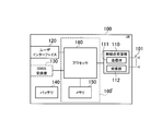
- FIG. 3 is a block diagram of the eNB 200.
- the eNB 200 includes a plurality of antennas 201, a radio transceiver 210, a network interface 220, a memory 230, and a processor 240.
- the memory 230 and the processor 240 constitute a control unit.
- the memory 230 may be integrated with the processor 240, and this set (ie, chip set) may be used as the processor.
- the plurality of antennas 201 and the wireless transceiver 210 are used for transmitting and receiving wireless signals.
- the radio transceiver 210 includes a transmission unit 211 that converts a baseband signal (transmission signal) output from the processor 240 into a radio signal and transmits the radio signal from the plurality of antennas 201.
- the radio transceiver 210 includes a reception unit 212 that converts radio signals received by the plurality of antennas 201 into baseband signals (reception signals) and outputs the baseband signals to the processor 240.
- the network interface 220 is connected to the neighboring eNB 200 via the X2 interface and is connected to the MME / S-GW 300 via the S1 interface.
- the network interface 220 is used for communication performed on the X2 interface and communication performed on the S1 interface.
- the memory 230 stores a program executed by the processor 240 and information used for processing by the processor 240.
- the processor 240 includes a baseband processor that performs modulation / demodulation and encoding / decoding of a baseband signal, and a CPU that executes a program stored in the memory 230 and performs various processes.
- the processor 240 executes various processes and various communication protocols described later.
- FIG. 4 is a protocol stack diagram of a radio interface in the LTE system. As shown in FIG. 4, the radio interface protocol is divided into layers 1 to 3 of the OSI reference model, and layer 1 is a physical (PHY) layer. Layer 2 includes a MAC (Media Access Control) layer, an RLC (Radio Link Control) layer, and a PDCP (Packet Data Convergence Protocol) layer. Layer 3 includes an RRC (Radio Resource Control) layer.
- PHY Physical
- Layer 2 includes a MAC (Media Access Control) layer, an RLC (Radio Link Control) layer, and a PDCP (Packet Data Convergence Protocol) layer.
- Layer 3 includes an RRC (Radio Resource Control) layer.
- RRC Radio Resource Control
- the physical layer performs encoding / decoding, modulation / demodulation, antenna mapping / demapping, and resource mapping / demapping. Data is transmitted between the physical layer of the UE 100 and the physical layer of the eNB 200 via a physical channel.
- the MAC layer performs data priority control, retransmission processing by hybrid ARQ (HARQ), and the like. Data is transmitted via the transport channel between the MAC layer of the UE 100 and the MAC layer of the eNB 200.
- the MAC layer of the eNB 200 includes a scheduler that determines uplink / downlink transport formats (transport block size, modulation / coding scheme (MCS)) and allocated resource blocks.
- MCS modulation / coding scheme
- the RLC layer transmits data to the RLC layer on the receiving side using the functions of the MAC layer and the physical layer. Data is transmitted between the RLC layer of the UE 100 and the RLC layer of the eNB 200 via a logical channel.
- the PDCP layer performs header compression / decompression and encryption / decryption.
- the RRC layer is defined only in the control plane. Control messages (RRC messages) for various settings are transmitted between the RRC layer of the UE 100 and the RRC layer of the eNB 200.
- the RRC layer controls the logical channel, the transport channel, and the physical channel according to establishment, re-establishment, and release of the radio bearer.
- RRC connected state When there is an RRC connection between the RRC of the UE 100 and the RRC of the eNB 200, the UE 100 is in a connected state (RRC connected state). Otherwise, the UE 100 is in an idle state (RRC idle state).
- the NAS (Non-Access Stratum) layer located above the RRC layer performs session management and mobility management.
- FIG. 5 is a configuration diagram of a radio frame used in the LTE system.
- OFDMA Orthogonal Frequency Division Multiplexing Access
- SC-FDMA Single Carrier Frequency Multiple Access
- the radio frame is composed of 10 subframes arranged in the time direction, and each subframe is composed of two slots arranged in the time direction.
- the length of each subframe is 1 ms, and the length of each slot is 0.5 ms.
- Each subframe includes a plurality of resource blocks (RB) in the frequency direction and includes a plurality of symbols in the time direction.
- the resource block includes a plurality of subcarriers in the frequency direction.
- a frequency resource can be specified by a resource block
- a time resource can be specified by a subframe (or slot).
- the section of the first few symbols of each subframe is a control region used mainly as a physical downlink control channel (PDCCH) for transmitting a control signal.
- the remaining section of each subframe is an area that can be used as a physical downlink shared channel (PDSCH) mainly for transmitting user data.
- PDSCH physical downlink shared channel
- both ends in the frequency direction in each subframe are control regions mainly used as a physical uplink control channel (PUCCH) for transmitting a control signal.
- the central portion in the frequency direction in each subframe is an area that can be used as a physical uplink shared channel (PUSCH) mainly for transmitting user data.
- PUSCH physical uplink shared channel
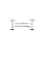
- FIG. 6 is a diagram showing an operating environment according to the present embodiment.
- pico eNBs (PeNBs) 200-2 and 200-3 are installed in the coverage of the macro eNB (MeNB) 200-1. That is, MeNB200-1 and PeNB200-2 are adjacent to each other, and MeNB200-1 and PeNB200-3 are adjacent to each other.
- MeNB 200-1 manages a large cell (macro cell). Each of the PeNBs 200-2 and 200-3 manages a small cell (pico cell). Further, the UE 100 is located within the coverage of the PeNB 200-2, and the UE 100 is connected to the PeNB 200-2. An X2 interface is established between the MeNB 200-1 and the PeNB 200-2 and between the MeNB 200-1 and the PeNB 200-3. An X2 interface may be established between PeNBs 200-2 and 200-3.
- the power saving communication mode is a mode in which communication with the UE 100 is performed in a state where the power consumption of the eNB 200 is reduced.
- the power saving communication mode is appropriately referred to as a “partial OFF mode”. Details of the power saving communication mode will be described later.
- the PeNB 200-2 sets the power saving communication mode in the operating environment shown in FIG.
- the communication capacity and / or communication quality in the PeNB 200-2 decreases, and thus there is a possibility that QoS (Quality of Service) required for communication of the UE 100 may not be satisfied.
- QoS refers to delay time, throughput (bandwidth), jitter, and the like.
- the PeNB 200-2 sets the neighbor cell (MeNB 200-1) based on the QoS required for communication with the UE 100 (hereinafter referred to as “request QoS”) before setting the power saving communication mode.
- the handover of the UE 100 is controlled.
- the PeNB 200-2 sets the power saving communication mode after performing handover of the UE 100 when the requested QoS cannot be satisfied when the power saving communication mode is set.
- the energy saving of PeNB200-2 is realizable, suppressing the fall of service quality.
- the signaling and processing load can be suppressed by not performing the handover of the UE 100.
- the PeNB 200-2 sets the power saving communication mode in response to the PeNB 200-2 receiving a request for setting the power saving communication mode (Partial OFF Request) from the MeNB 200-1.
- the power saving communication mode of the PeNB 200-2 can be set under the initiative of the MeNB 200-1.
- the PeNB 200-2 transmits an inquiry (Partial OFF Inquiry) as to whether or not the power saving communication mode is permitted to the MeNB 200-1.
- the PeNB 200-2 sets the power saving communication mode in response to the PeNB 200-2 receiving from the MeNB 200-1 an acknowledgment (Partial OFF Response) in response to the inquiry (Partial OFF Inquiry).
- the power saving communication mode of the PeNB 200-2 can be set under the initiative of the PeNB 200-2.
- the PeNB 200-2 may set the power saving communication mode without receiving a request or permission from the MeNB 200-1 (operation pattern 3).
- the PeNB 200-2 includes information indicating handover for the power saving communication mode (that is, energy saving) in the handover request transmitted to the MeNB 200-1 in the handover procedure.
- the MeNB 200-1 can make a determination in consideration of the necessity of the power saving communication mode when determining whether to accept the handover request.
- the PeNB 200-2 transmits a completion notification (Partial OFF Complete) indicating that the power saving communication mode is set to the MeNB 200-1.
- a completion notification (Partial OFF Complete) indicating that the power saving communication mode is set to the MeNB 200-1.
- the MeNB 200-1 can recognize that the PeNB 200-2 is in the power saving communication mode.
- the PeNB 200-2 may also perform signaling to the PeNB 200-3.
- the PeNB 200-2 may transmit a completion notification (Partial OFF Complete) indicating that the power saving communication mode is set to the PeNB 200-3.
- the types of power saving communication modes are “Discontinuous Transmission (DTX)”, “Reduction of Number of Transmitting Antennas (ANT reduced)”, “Transmission Power Reduction (TxPower reduced)”, and “Reduction of Processing Capacity (Capacity reduced)”. and so on.
- the intermittent transmission is a power saving communication mode in which the eNB 200 intermittently transmits a radio signal.
- FIG. 7 is a diagram for explaining intermittent transmission according to the present embodiment. As illustrated in FIG. 7, the eNB 200 intermittently transmits a cell-specific reference signal (CRS). In the example of FIG. 7, the CRS is transmitted once every 5 subframes.
- the eNB 200 sets a transmission stop period (DTX period) in a period (subframe) in which CRS is not transmitted. In the transmission stop period, since power supply to the transmission unit 211 (particularly, the power amplifier) of the eNB 200 can be stopped, energy saving can be realized.
- DTX period transmission stop period
- the reduction in the number of transmission antennas is a power saving communication mode in which the number of antennas used by the eNB 200 for transmitting radio signals (hereinafter referred to as “number of used antennas”) is reduced.
- FIG. 8 is a diagram for explaining a reduction in the number of transmission antennas according to the present embodiment. As illustrated in FIG. 8, the eNB 200 transmits a radio signal using only a part of the plurality of antennas 201. By reducing the number of used antennas, the power consumption of the eNB 200 (particularly, the transmission unit 211) is reduced, so that energy saving can be realized.
- the transmission power reduction is a power saving communication mode in which the eNB 200 reduces transmission power and redundantly transmits transmission data using surplus radio resources.
- the power consumption of the eNB 200 (particularly, the transmission unit 211) is reduced, so that energy saving of the eNB 200 can be realized.
- Processing capacity reduction is a power-saving communication mode in which the upper limit value of the processing capacity of the eNB 200 is kept below a predetermined value while maintaining the coverage of the eNB 200.
- the predetermined value is not a value set so as not to exceed the limit of the processing capability of the processor 240, but a value set lower than the limit of the processing capability of the processor 240.
- the communication capacity reduction is a power saving communication mode in which the number of UEs that can be connected to the eNB 200 or the amount of radio resources that can be allocated by the eNB 200 is limited. By performing such a restriction, power consumption of the eNB 200 (particularly, the processor 240) is reduced, so that energy saving of the eNB 200 can be realized.
- the number of UEs to be processed simultaneously includes the number of UEs to be scheduled and the number of UEs to be controlled.
- the reception function of the radio transceiver 210 of the eNB 200 is in a receivable state (or a state in which intermittent reception is possible).
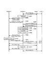
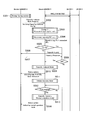
- FIG. 9 is a sequence diagram of the operation pattern 1 according to the present embodiment.
- operation pattern 1 energy saving of PeNB 200-2 is performed under the initiative of MeNB 200-1.
- MeNB 200-1 In the initial state, UEs 100-1 and 100-2 are connected to PeNB 200-2.
- step S101 the MeNB 200-1 determines whether or not to perform energy saving for the PeNB 200-2. This determination is performed according to any of the following first determination method to third determination method.
- the MeNB 200-1 determines that the PeNB 200-2 is based on temporal changes in traffic conditions (the number of connected UEs, the amount of transmitted / received data, or the radio resource usage rate) in the MeNB 200-1 and / or the PeNB 200-2. Determine whether to perform energy saving. For example, the MeNB 200-1 determines to perform the energy saving of the PeNB 200-2 in a time zone where the amount of transmitted / received data is small. Alternatively, the MeNB 200-1 determines to perform energy saving of the PeNB 200-2 when the number of connected UEs of the PeNB 200-2 falls below a threshold value.
- the MeNB 200-1 determines whether or not to perform energy saving of the PeNB 200-2 based on an instruction (energy saving ON / OFF command) from an OAM (Operation and Maintenance).
- an instruction energy saving ON / OFF command
- OAM Operaation and Maintenance
- the MeNB 200-1 determines whether to perform energy saving based on the power supply status of the MeNB 200-1 or the power supply status of the PeNB 200-2. If the MeNB 200-1 is notified of the power supply status of the PeNB 200-2, the MeNB 200-1 can grasp the power supply status of the PeNB 200-2. For example, when the power supply of the PeNB 200-2 is cut off (when the battery is driven), the MeNB 200-1 is when the remaining battery level of the PeNB 200-2 falls below a specified value, or the private power generation of the PeNB 200-2 When the output power of (e.g., solar) falls below a specified value, it is determined that energy saving of PeNB 200-2 is performed.
- the output power of e.g., solar
- the MeNB 200-1 transmits a power-saving communication mode setting request (Partial OFF Request) to the PeNB 200-2.
- the setting request (Partial OFF Request) includes information indicating at least one of the type and setting of the power saving communication mode required for the PeNB 200-2.
- the setting of the power saving communication mode is, for example, an intermittent transmission pattern (such as the start cycle of the transmission unit 211 or the transmission stop subframe number (or transmission stop system frame number)) if the type of the power saving communication mode is intermittent transmission If the type of the power saving communication mode is a reduction in the number of transmission antennas, the number of transmission antennas (or the number of antennas to be stopped) is used.
- step S103 the PeNB 200-2 calculates the communication capacity of the own cell when the requested power saving communication mode is set in response to the reception of the setting request (Partial OFF Request).
- the PeNB 200-2 confirms the requested QoS of each of the UEs 100 (UEs 100-1 and 100-2) in the own cell.
- the requested QoS is determined based on, for example, a QCI (Quality Class Identifier) corresponding to a radio bearer established by the UE.
- QCI Quality Class Identifier
- Step S105 the PeNB 200-2 determines whether or not to perform the handover of the UE 100 in the own cell depending on whether or not the requested QoS can be satisfied when the requested power saving communication mode is set. If the requested QoS cannot be satisfied when the power saving communication mode is set, it is determined that the UE 100 that does not satisfy the requested QoS is to be handed over. Here, the description will be made assuming that it is determined that the UE 100-1 is to be handed over.
- step S106 the PeNB 200-2 transmits setting information (Measurement Config.) For instructing measurement of the reception state (reception power and / or reception quality) to the UE 100-1.
- setting information Measurement Config.
- step S107 the UE 100-1 measures the serving cell (PeNB 200-2) and the neighboring cell (MeNB 200-1) based on the setting information (Measurement Config.), And reports the measurement result (Measurement Report) to the PeNB 200-2. Send to.
- step S108 the PeNB 200-2 determines the handover destination of the UE 100-1 based on the measurement result report (Measurement Report) from the UE 100-1.
- the measurement result report Measurement Report
- step S109 the PeNB 200-2 transmits a handover request to the MeNB 200-1.
- the MeNB 200-1 determines whether to accept the handover request.
- the handover request may include information indicating that the handover is for the power saving communication mode (that is, energy saving).
- step S111 the MeNB 200-1 transmits an acknowledgment (ACK) to the handover request to the PeNB 200-2.
- ACK acknowledgment
- Step S112 the PeNB 200-2 transmits a handover instruction (Handover Command) to the MeNB 200-1 to the UE 100-1 in response to the reception of the acknowledgment (ACK).
- a handover instruction Handover Command
- ACK acknowledgment
- step S113 the UE 100-1 performs handover to the MeNB 200-1 in response to reception of the handover instruction (Handover Command). Then, the UE 100-1 establishes a connection with the MeNB 200-1 by handover (step S114).
- step S115 the PeNB 200-2 sets the requested power saving communication mode (Partial OFF).
- step S116 the PeNB 200-2 transmits a completion notification (Partial OFF Complete) to the MeNB 200-1 indicating that the power saving communication mode has been set.
- the completion notification (Partial OFF Complete) may include information indicating at least one of the type and setting of the power saving communication mode set by the PeNB 200-2.
- the MeNB 200-1 can perform appropriate control in consideration of the type and setting of the power saving communication mode of the PeNB 200-2.
- the PeNB 200-2 is performing intermittent transmission (DTX) in which transmission is stopped in a specific subframe (or a specific frame)
- the MeNB 200-1 is in the specific subframe (or the specific frame).
- An MCS having a high data rate (that is, a predetermined value or more) can be assigned to the UE 100 under its control.
- the MeNB 200-1 can assign an MCS having a modulation scheme of 64QAM to the UE 100 in the specific subframe.
- the MeNB 200-1 can perform appropriate measurement setting (Measurement Config.) For the UE 100 under its control in consideration of the type and setting of the power saving communication mode of the PeNB 200-2.
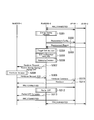
- FIG. 10 is a sequence diagram of an operation pattern 2 according to the present embodiment.
- the operation pattern 2 is a pattern for performing energy saving of the PeNB 200-2 led by the PeNB 200-2.
- UEs 100-1 and 100-2 are connected to PeNB 200-2. Note that description overlapping with the operation pattern 1 is omitted as appropriate.
- step S201 the PeNB 200-2 determines whether or not to perform its own energy saving. This determination is performed according to any of the following first determination method to third determination method.
- the PeNB 200-2 uses the energy saving of the PeNB 200-2 based on the time variation of the traffic situation in the own cell (such as the number of connected UEs in the cell, the amount of transmitted / received data, or the radio resource usage rate). It is determined whether or not to perform. Specifically, it is determined that energy saving is performed in a time zone in which traffic (amount of transmitted / received data) is small.
- PeNB 200-2 determines whether or not to perform energy saving based on an instruction (energy saving ON / OFF command) from OAM (Operation and Maintenance).
- the MeNB 200-1 determines whether to perform energy saving based on the power supply status of the MeNB 200-1 or the power supply status of the PeNB 200-2. If the PeNB 200-2 is notified of the power supply status of the MeNB 200-1, the PeNB 200-2 can grasp the power supply status of the MeNB 200-1. For example, when the power supply of the PeNB 200-2 is cut off (when the battery is driven), when the remaining battery level of the PeNB 200-2 falls below a specified value, the self-generated power (such as solar power) is the specified value. It is determined that energy saving is performed when the value is lower than.
- the PeNB 200-2 transmits an inquiry (Partial OFF Inquiry) as to whether or not the power saving communication mode is permitted to the MeNB 200-1.
- the inquiry includes information indicating the communication capacity required of the MeNB 200-1 by setting the power saving communication mode.
- the inquiry includes information indicating at least one of the type and setting of the power saving communication mode scheduled by the PeNB 200-2.
- the inquiry may include information indicating the number of UEs under the control of the PeNB 200-2.
- the MeNB 200-1 can perform the determination in consideration of the handover acceptance prediction and the number of affected UEs.
- the PeNB 200-2 may start a timer when an inquiry (Partial OFF Inquiry) is transmitted, and make an inquiry again when the timer exceeds a certain time.
- an inquiry Partial OFF Inquiry
- the MeNB 200-1 transmits an affirmative response (Partial OFF Response) to the PeNB 200-2 in response to the inquiry (Partial OFF Inquiry).
- the affirmative response (Partial OFF Response) may include information indicating the communication capacity (excess capacity) of the MeNB 200-1.
- step S204 the PeNB 200-2 transmits setting information (Measurement Config.) For instructing measurement of the reception state (reception power and / or reception quality) to each of the UEs 100-1 and 100-2.
- setting information Measurement Config.
- each of the UEs 100-1 and 100-2 performs measurement on the serving cell (PeNB200-2) and the neighboring cell (MeNB200-1) based on the setting information (Measurement Config.), And reports the measurement result (Measurement). Report) is transmitted to PeNB 200-2.
- step S206 the PeNB 200-2 determines the handover destination (candidate) of each of the UEs 100-1 and 100-2 based on the measurement report (Measurement Report) from each of the UEs 100-1 and 100-2. .
- MeNB 200-1 is determined as a handover destination (candidate).
- step S207 the PeNB 200-2 confirms the requested QoS of each of the UEs 100-1 and 100-2.
- the PeNB 200-2 determines whether to perform the handover of the UE 100-1 and / or 100-2 depending on whether the requested QoS can be satisfied when the power saving communication mode is set.
- the PeNB 200-2 may confirm whether or not the requested QoS can be satisfied based on the communication capacity of the own cell and / or the communication capacity of the neighboring cell (MeNB 200-1). For example, when the power saving communication mode is set, when the UE 100-1 determines that the requested QoS is not satisfied in the own cell, the MeNB 200-1 satisfies the requested QoS, and the UE 100-1 is handed over to the MeNB 200-1 to decide.
- step S209 the PeNB 200-2 transmits a handover request to the MeNB 200-1.
- the PeNB 200-2 includes information indicating that the handover is for the power saving communication mode (energy saving) in the handover request.
- step S210 the MeNB 200-1 determines whether to accept the handover request.
- the description will be made assuming that it is determined that the handover request is accepted.
- the subsequent procedure (steps S211 to S214) is the same as that of the operation pattern 1.
- steps S204 and S205 may be performed before step S202.
- the inquiry (Partial OFF Inquiry) can be performed after clarifying the handover destination of the UE 100 and calculating the necessary communication capacity.
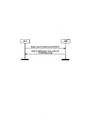
- FIG. 11 is a sequence diagram of the operation pattern 3 according to the present embodiment.
- the operation pattern 3 is different from the operation pattern 2 in that the PeNB 200-2 sets the power saving communication mode without making an inquiry to the MeNB 200-1, but the other procedures (steps S301 to S313) are the same as the operation pattern 2.
- the PeNB 200-2 may include information indicating at least one of the type and setting of the power saving communication mode in the handover request (step S307).
- step S101, step S201, and step S301 described above a predetermined priority order, or the processing capability / communication capacity of PeNB 200-2 (and / or MeNB 200-1) ( The power saving communication mode to be set by the PeNB 200-2 is selected based on (capacity).
- the order of priority may be the order in which interference with adjacent cells is reduced, or the order in which the coverage of the own cell is not affected.
- the power saving communication mode may be applied after sequentially estimating the communication capacity when the power saving communication mode is applied according to the priority order and confirming that the requested QoS is satisfied.
- the power saving communication mode may be applied according to the priority order, and the power saving communication mode may be reselected if the communication capacity at that time is greatly reduced.
- the power-saving communication mode may be (re) selected with the start or end of communication with the UE 100 as a trigger.
- FIG. 12 is a flowchart of the power saving communication mode selection process. Here, a case where the power saving communication mode is selected in the order of reducing interference will be described. Also, the PeNB 200-2 selects the power saving communication mode.
- the PeNB 200-2 determines whether or not the application is possible in the order of intermittent transmission (DTX), transmission antenna number reduction (ANT reduced), processing capacity reduction (Capacity reduced), and transmission power reduction (TxPower reduced). To do. Specifically, the PeNB 200-2 applies intermittent transmission (step S401), and applies a reduction in the number of transmission antennas if the communication capacity is sufficient (or if further power saving is necessary) (step S401). S402, S403).
- DTX intermittent transmission
- ANT reduced transmission antenna number reduction
- Capacity reduced processing capacity reduction
- TxPower reduced transmission power reduction
- the communication capacity reduction (processing capacity reduction) is applied (steps S404 and S405).
- the transmission power reduction is applied (steps S406 and S407).
- the communication stop mode may be finally applied.
- the above-mentioned X2 is used to send the above-described power saving communication mode setting notification (Partial OFF Complete), power saving communication mode setting request (Partial OFF Request), power saving communication mode inquiry (Partial OFF Inquiry). It may be an information element of a message.
- FIG. 13 and FIG. 14 are diagrams for explaining the eNB Configuration Update message according to the present embodiment.
- the eNB Configuration Update message is a kind of X2 message, and is mainly a message for notifying the neighboring eNB 200 of a setting change in the eNB 200.
- the eNB Configuration Update message according to the present embodiment includes information related to a power saving communication mode setting notification (Partial OFF Complete).
- the Cell Activation Request message is a kind of X2 message, and is mainly a message for the eNB 200 to request the neighboring eNB 200 to start a cell.
- the Cell Activation Request message according to the present embodiment includes information related to a power saving communication mode setting request (Partial OFF Request).
- the master eNB 200-3 is the eNB 200 that controls the energy saving of the slave eNB 200-4. Therefore, the relationship between the master eNB 200-3 and the slave eNB 200-4 may be not only the relationship between the MeNB 200-1 and the PeNB 200-2 but also the relationship of the eNB 200 in the same row. In the present embodiment, the relationship between the master eNB 200-3 and the slave eNB 200-4 is a relationship between adjacent eNBs. An X2 interface is established between the master eNB 200-3 and the slave eNB 200-4.
- the eNB 200 may negotiate to determine the master eNB 200-3 and the slave eNB 200-4.
- the eNB 200-4 requests the eNB 200-3 to control the setting of the power saving communication mode in the eNB 200-4 to the eNB 200-3. That is, the eNB 200-4 requests the eNB 200-3 to become the master eNB 200-4.
- the eNB 200-3 determines whether to accept the request from the eNB 200-4.
- the eNB 200-3 transmits a response indicating that the request from the eNB 200-4 is accepted to the eNB 200-4.
- the eNB 200-4 receives the response, the relationship between the master eNB 200-3 and the slave eNB 200-4 is established.
- the eNB 200-3 requests the eNB 200-4 to control the setting of the power saving communication mode in the eNB 200-4 to the eNB 200-4. That is, the eNB 200-3 requests the eNB 200-4 to become the slave eNB 200-4.
- the eNB 200-4 determines whether to accept the request from the eNB 200-3.
- the eNB 200-4 transmits a response to accept the request from the eNB 200-2 to the eNB 200-3.
- the eNB 200-3 receives the response, the relationship between the master eNB 200-3 and the slave eNB 200-4 is established.
- the request from the eNB 200-3 or the eNB 200-4 may include its own cell size (for example, transmission power).
- the eNB 200-3 or eNB 200-4 that has received the request may compare its own cell size (for example, transmission power) with the cell size of the transmission source of the request to determine whether to accept the request. Good.
- the eNB 200-3 or the eNB 200-4 may determine whether to accept the request based on master / slave eNB information indicating whether the neighboring eNB 200 is the master eNB 200 or the slave eNB 200.
- the other neighboring eNB 200 when the other neighboring eNB 200 is already the master eNB 200 in the eNB 200-4, it may be determined that the request from the eNB 200-3 is rejected, or the eNB 200-3 may be the master eNB 200-3 with respect to the other eNB 200. In some cases, it may be determined to accept a request from the eNB 200-4.
- the master / slave eNB information may be recorded in an adjacent cell list held by the eNB 200 or may be recorded in a dedicated table. The eNB 200-3 and the eNB 200-4 may exchange the dedicated table (for example, when the dedicated table is updated).
- the negotiation between the eNBs 200 may be determined by an instruction from an upper network (for example, OAM).
- OAM an upper network
- FIG. 17 is a sequence diagram of an operation pattern according to the second embodiment.
- step S501 the master eNB 200-3 determines whether to perform energy saving of the slave eNB 200-4. This determination is performed according to the determination method in step S101 of the operation pattern 1.
- the master eNB 200-3 transmits a power saving communication mode setting request to the slave eNB 200-4. Specifically, the master eNB 200-3 transmits, to the slave eNB 200-4, a setting request (Capacity-reduced Mode Request) including information indicating the setting of processing capacity reduction as the power saving communication mode. The slave eNB 200-4 receives the setting request.
- a setting request Capacity-reduced Mode Request
- the setting request includes setting information (Capacity-reduced Config.) For setting processing capacity reduction.
- the setting information include the upper limit number of UEs to be processed simultaneously, the time when the power saving communication mode starts, the time when the power saving communication mode ends, a timer value indicating the setting period of the power saving communication mode, and the like.
- step S503 the slave eNB 200-4 calculates the expected processing capacity C1 of the slave eNB 200-4 when it is assumed that the requested power saving communication mode is set according to the setting request.
- slave eNB 200-4 calculates request processing capability C2 currently requested by slave eNB 200-4. For example, the slave eNB 200-4 calculates the request processing capacity based on the number of connected UEs of the slave eNB 200-4.
- step S505 the slave eNB 200-4 determines whether or not the predicted processing capacity C1 is lower than the requested processing capacity C2.
- the slave eNB 200-4 executes the process of step S506 when the predicted processing capacity C1 is lower than the requested processing capacity C2 (in the case of “Yes”).
- the slave eNB 200-4 executes the process of step S509 when the predicted processing capacity C1 is not lower than the requested processing capacity C2 (in the case of “No”).
- step S506 slave eNB 200-4 transmits an inquiry (Capacity Inquiry) as to whether or not to set the power saving communication mode in accordance with the setting request to master eNB 200-3.
- the master eNB 200-3 receives the inquiry.
- the inquiry may include information indicating the expected processing capacity C1 and the requested processing capacity C2.
- the master eNB 200-3 determines whether to set the power saving communication mode according to the setting request.
- step S507 the master eNB 200-3 transmits to the slave eNB 200-4 a determination result (Capacity Response) as to whether or not to set the power saving communication mode as a response to the inquiry.
- the slave eNB 200-4 receives the determination result.
- the determination result includes information indicating that the power saving communication mode is set or not set according to the setting request.
- the determination result may include information indicating that another power saving communication mode is set together with information indicating that the power saving communication mode is not set according to the setting request.
- the master eNB 200-3 may transmit a new power saving communication mode setting request instead of the determination result.
- step S508 the slave eNB 200-4 determines whether or not to set the power saving communication mode based on the determination result. Slave eNB 200-4 executes the process of step S 509 when setting the power saving communication mode (in the case of “Yes”), and ends the process when not setting the power saving communication mode (in the case of “No”). .
- step S509 the slave eNB 200-4 performs the power saving communication mode according to the setting request.
- the slave eNB 200-4 sets the processing capacity reduction mode.
- step S510 the slave eNB 200-4 transmits the state update information (Status update) to the master eNB 200-3.
- the master eNB 200-3 receives the state update information.
- the state update information includes information related to the setting of the power saving communication mode, the upper limit number (max # of UEs) of UEs to be simultaneously processed in the set power saving communication mode, and a threshold (timer threshold) related to the end time of the power saving communication mode. Information indicating at least one of them is included.
- the thresholds related to the end time of the power communication mode include a time when the power saving communication mode is ended, a timer value indicating a setting period of the power saving communication mode (expired value of setting timer), and the like.
- the state update information includes information indicating that the processing capacity reduction mode is set.
- the slave eNB 200-4 may transmit the state update information not only to the master eNB 200-3 but also to an upper network (for example, OAM), the MeNB 200, the neighboring eNB 200, and the like.
- OAM an upper network
- step S511 the slave eNB 200-4 starts a power saving communication mode setting timer (recovery timer).
- step S512 the slave eNB 200-4 determines whether or not the setting timer has expired. Slave eNB 200-4 executes the process of step S513 when the setting timer expires (in the case of “Yes”), and repeats the process of step S512 when the setting timer has not expired (in the case of “No”). .
- step S513 the slave eNB 200-4 ends the power saving communication mode.
- the slave eNB 200-4 cancels the setting of the processing capacity reduction mode.
- step S514 slave eNB 200-4 transmits state update information to master eNB 200-3.
- the master eNB 200-3 receives the state update information.
- the state update information includes information indicating that the normal mode has been set.
- the handover destination candidate from PeNB 200-2 is only MeNB 200-1, but when there are a plurality of handover destination candidates, the capability or category (number of antennas, etc.) of UE 100 is determined. It is desirable to determine an appropriate handover destination in consideration.
- the eNB 200 determines whether the requested QoS can be satisfied when the requested power saving communication mode is set. Although it has been determined whether or not to perform the handover of the UE 100, the handover may be determined based not only on the requested QoS but also on the basis of RSRP (Reference Signal Received Power) or / and RSRQ (Reference Single Received Quality). . For example, the eNB 200 may determine whether or not to perform a handover of the UE 100 based on the requested QoS after determining whether or not the RSRP or / and RSRQ of the eNB 200 is less than the threshold.
- RSRP Reference Signal Received Power
- RSRQ Reference Single Received Quality
- the eNB 200 may determine handover based on not only the requested QoS but also RSRP or / and RSRQ.
- the eNB 200 performs handover based on RSRP or / and RSRQ when the requested QoS of at least one UE among all the UEs 100 in the own cell cannot be satisfied.
- the target UE 100 may be determined.
- eNB200 may determine UE100 whose request
- MBSFN MBMS Single Frequency Network
- ABS Almost Blank Subframe
- TDD DwPTS in Special Subframe A method in which the DwPTS in the Special Subframe included in the radio frame in the case of TDD is set to the minimum time and transmission is stopped outside the DwPTS time.
- TDD dynamic frame configuration A method in which the TDD frame setting (config.) Is set to minimize the downlink transmission subframe, and transmission is stopped at the uplink time.
- the power saving communication mode is set in the PeNB, but the power saving communication mode may be set in the MeNB.
- the MeNB 200-1 and the PeNB 200-2 may determine whether to end the setting of the power saving communication mode based on the determination criterion as to whether to perform the energy saving described above. For example, the MeNB 200-1 determines to end the setting of the power saving communication mode of the PeNB 200-2 when the number of connected UEs of the PeNB 200-2 exceeds a threshold value.
- the PeNB 200 uses information for determining whether to end the setting of the power saving communication mode as a periodic or predetermined trigger (for example, power saving communication). May be transmitted to the MeNB 200-1 according to the case where the mode setting criterion is not satisfied.
- the slave eNB 200-4 transmits state update information, but may transmit state update information in response to a request or inquiry from the master eNB 200-3.
- step S505 of the second embodiment described above if the expected processing capacity C1 is lower than the requested processing capacity C2, whether to perform handover of the UE 100 in the own cell based on the requested QoS and / or RSRP or / and RSRQ It may be determined whether or not.
- the slave eNB 200-4 has completed the setting of the power saving communication mode after the setting timer has expired, but is not limited thereto.
- the slave eNB 200-4 may determine whether or not to continue the setting of the power saving communication mode according to the criterion for determining whether or not to perform energy saving according to the first embodiment.
- the operations of the master eNB 200-3 and the slave eNB 200-4 in the second embodiment described above may be appropriately performed by the MeNB 200-1 and the PeNB 200-2 in the above-described embodiment.
- the operations of the MeNB 200-1 and the PeNB 200-2 in the above-described embodiment may be appropriately performed by the master eNB 200-3 and the slave eNB 200-4. Therefore, for example, when the power saving communication mode is set, the PeNB 200-2 may transmit the state update information to the MeNB 200-1.
- heterogeneous network configuration including MeNB and PeNB was assumed, other network configurations may be used.
- the present invention is not limited to the LTE system, and the present invention may be applied to a system other than the LTE system.
- the base station according to the present invention is useful in the mobile communication field because it can realize energy saving while suppressing deterioration in service quality.
Landscapes
- Engineering & Computer Science (AREA)
- Computer Networks & Wireless Communication (AREA)
- Signal Processing (AREA)
- Mobile Radio Communication Systems (AREA)
Abstract
Description
実施形態に係る基地局は、自セル内のユーザ端末との通信を行う。前記基地局は、前記基地局の消費電力が削減された状態で前記ユーザ端末との通信を行う省電力通信モードを設定する前において、への前記ユーザ端末のハンドオーバを制御する制御部を備える。
以下、図面を参照して、3GPPで標準化されているLTE(Long Term Evolution)に本発明を適用する場合の実施形態を説明する。
図1は、第1実施形態に係るLTEシステムの構成図である。図1に示すように、LTEシステムは、複数のUE(User Equipment)100と、E-UTRAN(Evolved Universal Terrestrial Radio Access Network)10と、EPC(Evolved Packet Core)20と、を含む。E-UTRAN10は無線アクセスネットワークに相当し、EPC20はコアネットワークに相当する。E-UTRAN10及びEPC20は、LTEシステムのネットワークを構成する。
(1)動作概要
図6は、本実施形態に係る動作環境を示す図である。図6に示すように、マクロeNB(MeNB)200-1のカバレッジ内にピコeNB(PeNB)200-2及び200-3が設置されている。すなわち、MeNB200-1及びPeNB200-2は互いに隣接し、MeNB200-1及びPeNB200-3は互いに隣接する。
上述したように、本実施形態では、eNB200の消費電力を削減する方法が異なる複数種類の省電力通信モードが規定されている。
次に、本実施形態に係る動作シーケンスについて、動作パターン1から3の順に説明する。
図9は、本実施形態に係る動作パターン1のシーケンス図である。動作パターン1では、MeNB200-1主導でPeNB200-2のエナジーセービングを行う。初期状態において、PeNB200-2にはUE100-1及び100-2が接続している。
図10は、本実施形態に係る動作パターン2のシーケンス図である。動作パターン2は、PeNB200-2主導でPeNB200-2のエナジーセービングを行うパターンである。初期状態において、PeNB200-2にはUE100-1及び100-2が接続している。尚、動作パターン1と重複する説明については適宜省略する。
図11は、本実施形態に係る動作パターン3のシーケンス図である。
上述したステップS101、ステップS201、及びステップS301においては、予め定められた優先順位、又は、PeNB200-2(及び/又はMeNB200-1)の処理能力/通信容量(キャパシティ)に基づいて、PeNB200-2が設定すべき省電力通信モードが選択される。優先順位は、隣接セルへの干渉を低減する順であってもよく、自セルのカバレッジに影響が無い順であってもよい。
上述した省電力通信モードの設定通知(Partial OFF Complete)、省電力通信モードの設定要求(Partial OFF Request)、省電力通信モードの問い合わせ(Partial OFF Inquiry)を、既存のX2メッセージの情報要素としてもよい。
次に、第2実施形態について説明する。なお、上述の実施形態と異なる部分を中心に説明し、同様の部分は、説明を適宜省略する。
本実施形態に係る動作概要を説明する。
次に、第2実施形態に係る動作シーケンスについて、図17を用いて説明する。図17は、第2実施形態に係る動作パターンのシーケンス図である。
上述した実施形態では、PeNB200-2からのハンドオーバ先候補がMeNB200-1のみである場合を想定していたが、ハンドオーバ先候補が複数存在する場合にはUE100の能力又はカテゴリ(アンテナ本数など)を考慮して適切なハンドオーバ先を決定することが望ましい。
Claims (22)
- 自セル内のユーザ端末との通信を行う基地局であって、
前記基地局の消費電力が削減された状態で前記ユーザ端末との通信を行う省電力通信モードを設定する前において、隣接基地局への前記ユーザ端末のハンドオーバを制御する制御部を備えることを特徴とする基地局。 - 前記制御部は、前記ユーザ端末との通信に要求されるQoSに基づいて、前記隣接基地局への前記ユーザ端末のハンドオーバを制御することを特徴とする請求項1に記載の基地局。
- 前記制御部は、前記省電力通信モードを設定すると前記QoSを満たせない場合に、前記ハンドオーバを行った上で、前記省電力通信モードを設定することを特徴とする請求項2に記載の基地局。
- 前記制御部は、前記ハンドオーバの手続において前記隣接基地局に送信するハンドオーバ要求に、前記省電力通信モードのためのハンドオーバであることを示す情報を含めることを特徴とする請求項3に記載の基地局。
- 前記制御部は、前記省電力通信モードの設定要求を前記基地局が前記隣接基地局から受信したことに応じて、前記省電力通信モードを設定することを特徴とする請求項1に記載の基地局。
- 前記基地局の消費電力を削減する方法が異なる複数種類の省電力通信モードが規定されており、
前記設定要求は、前記基地局に要求される前記省電力通信モードの種類及び設定のうち少なくとも一方を示す情報を含むことを特徴とする請求項5に記載の基地局。 - 前記制御部は、前記省電力通信モードが許可されるか否かの問い合わせを隣接基地局に送信し、
前記制御部は、前記問い合わせに対する肯定応答を前記基地局が前記隣接基地局から受信したことに応じて、前記省電力通信モードを設定することを特徴とする請求項1に記載の基地局。 - 前記基地局の消費電力を削減する方法が異なる複数種類の省電力通信モードが規定されており、
前記問い合わせは、前記基地局が予定する前記省電力通信モードの種類及び設定のうち少なくとも一方を示す情報を含むことを特徴とする請求項7に記載の基地局。 - 前記問い合わせは、前記省電力通信モードを設定することにより前記隣接基地局に要求される通信容量を示す情報、及び/又は前記基地局の配下のユーザ端末の数を示す情報を含むことを特徴とする請求項7に記載の基地局。
- 前記制御部は、前記省電力通信モードを設定した場合に、前記省電力通信モードを設定したことを示す完了通知を前記隣接基地局に送信することを特徴とする請求項1に記載の基地局。
- 前記基地局の消費電力を削減する方法が異なる複数種類の省電力通信モードが規定されており、
前記完了通知は、前記基地局が設定した前記省電力通信モードの種類及び設定のうち少なくとも一方を示す情報を含むことを特徴とする請求項10に記載の基地局。 - 前記省電力通信モードの設定を示す情報は、前記省電力通信モードが適用されるシステムフレーム番号及びサブフレーム番号の少なくともいずれかを含むことを特徴とする請求項11に記載の基地局。
- 前記省電力通信モードの設定を示す情報は、前記隣接基地局において、前記サブフレーム番号が示すサブフレーム内の無線リソース、又は、前記シスレムフレーム番号が示すフレームを構成するサブフレーム内の無線リソースが割り当てられる前記ユーザ端末に対して、データレートが所定値以上となるMCSを割り当てるために用いられることを特徴とする請求項12に記載の基地局。
- 前記基地局の消費電力を削減する方法が異なる複数種類の省電力通信モードが規定されており、
予め定められた優先順位、又は、前記基地局の通信容量に基づいて、前記複数種類の省電力通信モードの中から、前記基地局が設定すべき省電力通信モードが選択されることを特徴とする請求項1に記載の基地局。 - 自セル内のユーザ端末との通信を行う基地局であって、
前記基地局の消費電力を削減する方法が異なる複数種類の省電力通信モードが規定されており、
前記基地局は、前記複数種類の省電力通信モードの中から選択された省電力通信モードの種類及び設定のうち少なくとも一方を示す情報を隣接基地局に通知する制御部を備えることを特徴とする基地局。 - 前記複数種類の省電力通信モードの中から省電力通信モードを設定することを要求する設定要求を前記隣接基地局から受信する受信部をさらに備え、
前記制御部は、前記複数種類の省電力通信モードの中から前記省電力通信モードを選択し、
前記制御部は、前記設定要求を送信した前記隣接基地局に対して、前記情報を通知することを特徴とする請求項15に記載の基地局。 - 前記制御部は、前記隣接基地局に対して、前記基地局における前記省電力通信モードの設定を前記隣接基地局が制御することを要求し、
前記受信部は、前記要求を受け入れる旨の応答を受信した前記隣接基地局から前記設定要求を受信することを特徴とする請求項16に記載の基地局。 - 前記受信部は、前記隣接基地局から、前記基地局における前記省電力通信モードの設定を前記隣接基地局が制御する旨の要求を受信し、
前記受信部は、前記制御部が前記要求を受け入れる旨の回答を前記隣接基地局に送信した場合に、前記隣接基地局から前記設定要求を受信することを特徴とする請求項16に記載の基地局。 - 前記制御部は、前記基地局における前記省電力通信モードの設定を制御する前記隣接基地局が記録されたリストを保持し、
前記制御部は、前記リストに基づいて、前記情報を前記隣接基地局に通知することを特徴とする請求項16に記載の基地局。 - 前記設定要求は、前記複数種類の省電力通信モードの中から前記基地局が設定すべき省電力通信モードとして、前記基地局のカバレッジを維持しつつ前記基地局の処理負荷の上限値を所定値未満に抑えるモードを要求する情報を含むことを特徴とする請求項16に記載の基地局。
- 前記設定要求は、前記省電力通信モードを開始する時刻、前記省電力通信モードを終了する時刻、及び、前記省電力通信モードの設定期間を示すタイマ値の少なくともいずれかを示す情報を含むことを特徴とする請求項16に記載の基地局。
- 前記制御部は、前記設定要求に従って前記省電力通信モードが設定されたと仮定した場合における前記基地局の予想処理能力が、前記基地局が現在要求されている処理能力を下回る場合、前記設定要求に従って前記省電力通信モードを設定するか否かの問い合わせを前記隣接基地局に通知することを特徴とする請求項16に記載の基地局。
Priority Applications (3)
| Application Number | Priority Date | Filing Date | Title |
|---|---|---|---|
| EP14779923.3A EP2983420A4 (en) | 2013-04-05 | 2014-04-03 | BASE STATION |
| JP2015510125A JP6169167B2 (ja) | 2013-04-05 | 2014-04-03 | 基地局、プロセッサ、及び移動通信システム |
| US14/781,496 US20160057689A1 (en) | 2013-04-05 | 2014-04-03 | Base station |
Applications Claiming Priority (4)
| Application Number | Priority Date | Filing Date | Title |
|---|---|---|---|
| JP2013080002 | 2013-04-05 | ||
| JP2013-080002 | 2013-04-05 | ||
| JP2013224466 | 2013-10-29 | ||
| JP2013-224466 | 2013-10-29 |
Publications (1)
| Publication Number | Publication Date |
|---|---|
| WO2014163138A1 true WO2014163138A1 (ja) | 2014-10-09 |
Family
ID=51658429
Family Applications (1)
| Application Number | Title | Priority Date | Filing Date |
|---|---|---|---|
| PCT/JP2014/059830 Ceased WO2014163138A1 (ja) | 2013-04-05 | 2014-04-03 | 基地局 |
Country Status (4)
| Country | Link |
|---|---|
| US (1) | US20160057689A1 (ja) |
| EP (1) | EP2983420A4 (ja) |
| JP (1) | JP6169167B2 (ja) |
| WO (1) | WO2014163138A1 (ja) |
Cited By (9)
| Publication number | Priority date | Publication date | Assignee | Title |
|---|---|---|---|---|
| WO2017037985A1 (ja) * | 2015-08-28 | 2017-03-09 | パナソニックIpマネジメント株式会社 | 移動無線端末および制御方法 |
| JP2017163499A (ja) * | 2016-03-11 | 2017-09-14 | 株式会社Nttドコモ | 無線通信システム及び管理装置 |
| JP2017169121A (ja) * | 2016-03-17 | 2017-09-21 | Necプラットフォームズ株式会社 | 無線lan中継装置、ホスト装置、通信方法、および通信システム |
| JP2018198443A (ja) * | 2018-07-27 | 2018-12-13 | Necプラットフォームズ株式会社 | ホスト装置、通信方法、および通信システム |
| WO2019146722A1 (ja) * | 2018-01-29 | 2019-08-01 | 日本電気株式会社 | 端末装置、基地局、コアネットワークノード、方法、プログラム、及びコンピュータに読み取り可能な非一時的記録媒体 |
| JP2019523611A (ja) * | 2016-09-14 | 2019-08-22 | グーグル エルエルシー | スモールセル熱制御 |
| US11310673B2 (en) | 2018-01-29 | 2022-04-19 | Nec Corporation | Communication apparatus, base station, terminal apparatus, method, program, and a non-transitory computer readable recording medium |
| JP2025509429A (ja) * | 2022-03-10 | 2025-04-11 | ノキア テクノロジーズ オサケユイチア | セルシャットダウン中の高速オフロードのためのcho構成 |
| WO2025203240A1 (ja) * | 2024-03-26 | 2025-10-02 | Ntt株式会社 | リクエスト受付量制御装置、リクエスト受付量制御方法およびプログラム |
Families Citing this family (5)
| Publication number | Priority date | Publication date | Assignee | Title |
|---|---|---|---|---|
| EP3304972B1 (en) * | 2015-06-02 | 2019-08-07 | Telefonaktiebolaget LM Ericsson (publ) | Adapting qos for a radio bearer having two associated qos by means of a ue indication |
| US20170290067A1 (en) * | 2016-03-29 | 2017-10-05 | Intel IP Corporation | Apparatus, system and method of establishing a session |
| WO2019136645A1 (zh) * | 2018-01-10 | 2019-07-18 | Oppo广东移动通信有限公司 | 用于确定终端设备状态的方法、终端设备和接入网设备 |
| CN110858994A (zh) * | 2018-08-23 | 2020-03-03 | 中国移动通信有限公司研究院 | 一种节能信息发送方法、装置和存储介质 |
| US20230284328A1 (en) * | 2022-03-03 | 2023-09-07 | Qualcomm Incorporated | Energy saving coordination in a network |
Citations (4)
| Publication number | Priority date | Publication date | Assignee | Title |
|---|---|---|---|---|
| WO2011091958A1 (en) * | 2010-01-28 | 2011-08-04 | Alcatel Lucent | Network node control |
| WO2012063834A1 (ja) * | 2010-11-10 | 2012-05-18 | 京セラ株式会社 | 基地局及びその制御方法 |
| JP2013080002A (ja) | 2011-09-30 | 2013-05-02 | Fujifilm Corp | パターン形成方法、感電子線性又は感極紫外線性樹脂組成物、及び、レジスト膜、並びに、これらを用いた電子デバイスの製造方法、及び、電子デバイス |
| JP2013224466A (ja) | 2012-04-20 | 2013-10-31 | Nippon Steel & Sumikin Engineering Co Ltd | 熱風管の冷却方法および補修方法 |
Family Cites Families (10)
| Publication number | Priority date | Publication date | Assignee | Title |
|---|---|---|---|---|
| KR101398628B1 (ko) * | 2007-02-12 | 2014-05-22 | 삼성전자주식회사 | 이동 단말의 절전 모드를 이용한 핸드오프 제어 시스템 및그 제어 방법 |
| EP2180741A1 (en) * | 2008-10-27 | 2010-04-28 | Nokia Siemens Networks OY | Apparatus and method for dynamically deploying a network node |
| WO2010077193A1 (en) * | 2008-12-29 | 2010-07-08 | Telefonaktiebolaget L M Ericsson (Publ) | Device, packet and method for power saving |
| EP2214436B1 (en) * | 2009-01-29 | 2013-03-20 | Alcatel Lucent | Telecommunication method and apparatus thereof |
| BR122020017793B1 (pt) * | 2010-02-12 | 2022-09-27 | Mitsubishi Electric Corporation | Sistema de comunicação móvel, estação base e terminal móvel |
| CN102695253B (zh) * | 2011-03-25 | 2016-08-03 | 中兴通讯股份有限公司 | 一种基站节能信息的传递方法及节能实现方法与系统 |
| US20140071877A1 (en) * | 2011-05-11 | 2014-03-13 | Nec Corporation | Communication system, management apparatus, control method, and program |
| US9084117B2 (en) * | 2012-07-03 | 2015-07-14 | Telefonaktiebolaget L M Ericsson (Publ) | Dynamic mobility management in cell-breathing base stations in a cellular telecommunication network |
| US9614630B2 (en) * | 2012-11-15 | 2017-04-04 | Telefonaktiebolaget Lm Ericsson (Publ) | Network node and a method therein, and a radio base station and a method therein for protecting control channels of a neighbouring radio base station |
| US20140295849A1 (en) * | 2013-03-29 | 2014-10-02 | Alexander Sirotkin | Handover of user equipment with non-gbr bearers |
-
2014
- 2014-04-03 JP JP2015510125A patent/JP6169167B2/ja active Active
- 2014-04-03 US US14/781,496 patent/US20160057689A1/en not_active Abandoned
- 2014-04-03 WO PCT/JP2014/059830 patent/WO2014163138A1/ja not_active Ceased
- 2014-04-03 EP EP14779923.3A patent/EP2983420A4/en not_active Withdrawn
Patent Citations (4)
| Publication number | Priority date | Publication date | Assignee | Title |
|---|---|---|---|---|
| WO2011091958A1 (en) * | 2010-01-28 | 2011-08-04 | Alcatel Lucent | Network node control |
| WO2012063834A1 (ja) * | 2010-11-10 | 2012-05-18 | 京セラ株式会社 | 基地局及びその制御方法 |
| JP2013080002A (ja) | 2011-09-30 | 2013-05-02 | Fujifilm Corp | パターン形成方法、感電子線性又は感極紫外線性樹脂組成物、及び、レジスト膜、並びに、これらを用いた電子デバイスの製造方法、及び、電子デバイス |
| JP2013224466A (ja) | 2012-04-20 | 2013-10-31 | Nippon Steel & Sumikin Engineering Co Ltd | 熱風管の冷却方法および補修方法 |
Non-Patent Citations (6)
| Title |
|---|
| "TS36.300 Vll.4.0", 3GPP TECHNIQUE SPECIFICATION, December 2012 (2012-12-01) |
| CMCC: "Consideration on Possible Solutions for Network Energy Saving", 3GPP TSG RAN WG1 MEETING #60, R1-101620, February 2010 (2010-02-01), XP050598101 * |
| NOKIA SIEMENS NETWORKS, NOKIA: "Issues and Enhanced Framework for the Energy Saving Use Case, R3-080813", 3GPP TSG-RAN WG3 MEETING #59-BIS, April 2008 (2008-04-01), XP050164011 * |
| SAMSUNG: "Proposed Description for Inter-eNB Energy Saving", 3GPP TSG RAN WG3 MEETING #69, R3-102143, August 2010 (2010-08-01), pages 1 - 5, XP050453021 * |
| See also references of EP2983420A4 |
| ZTE: "LTE energy saving solution, R3-100823", 3GPP TSG- RAN3 MEETING #67, February 2010 (2010-02-01), pages 1 - 5, XP050424611 * |
Cited By (12)
| Publication number | Priority date | Publication date | Assignee | Title |
|---|---|---|---|---|
| WO2017037985A1 (ja) * | 2015-08-28 | 2017-03-09 | パナソニックIpマネジメント株式会社 | 移動無線端末および制御方法 |
| US9949187B2 (en) | 2015-08-28 | 2018-04-17 | Panasonic Intellectual Property Management Co., Ltd. | Mobile wireless terminal and control method |
| JP2017163499A (ja) * | 2016-03-11 | 2017-09-14 | 株式会社Nttドコモ | 無線通信システム及び管理装置 |
| US10505593B2 (en) | 2016-03-11 | 2019-12-10 | Ntt Docomo, Inc. | Wireless communication system and management apparatus |
| JP2017169121A (ja) * | 2016-03-17 | 2017-09-21 | Necプラットフォームズ株式会社 | 無線lan中継装置、ホスト装置、通信方法、および通信システム |
| JP2019523611A (ja) * | 2016-09-14 | 2019-08-22 | グーグル エルエルシー | スモールセル熱制御 |
| WO2019146722A1 (ja) * | 2018-01-29 | 2019-08-01 | 日本電気株式会社 | 端末装置、基地局、コアネットワークノード、方法、プログラム、及びコンピュータに読み取り可能な非一時的記録媒体 |
| US11310673B2 (en) | 2018-01-29 | 2022-04-19 | Nec Corporation | Communication apparatus, base station, terminal apparatus, method, program, and a non-transitory computer readable recording medium |
| JP2018198443A (ja) * | 2018-07-27 | 2018-12-13 | Necプラットフォームズ株式会社 | ホスト装置、通信方法、および通信システム |
| JP2025509429A (ja) * | 2022-03-10 | 2025-04-11 | ノキア テクノロジーズ オサケユイチア | セルシャットダウン中の高速オフロードのためのcho構成 |
| JP7756268B2 (ja) | 2022-03-10 | 2025-10-17 | ノキア テクノロジーズ オサケユイチア | セルシャットダウン中の高速オフロードのためのcho構成 |
| WO2025203240A1 (ja) * | 2024-03-26 | 2025-10-02 | Ntt株式会社 | リクエスト受付量制御装置、リクエスト受付量制御方法およびプログラム |
Also Published As
| Publication number | Publication date |
|---|---|
| JPWO2014163138A1 (ja) | 2017-02-16 |
| EP2983420A4 (en) | 2016-08-24 |
| JP6169167B2 (ja) | 2017-07-26 |
| EP2983420A1 (en) | 2016-02-10 |
| US20160057689A1 (en) | 2016-02-25 |
Similar Documents
| Publication | Publication Date | Title |
|---|---|---|
| JP6169167B2 (ja) | 基地局、プロセッサ、及び移動通信システム | |
| JP6475885B2 (ja) | 無線基地局、ユーザ端末及びプロセッサ | |
| JP6910310B2 (ja) | 無線端末 | |
| CN109156005B (zh) | 基站和用户终端 | |
| JP6062088B2 (ja) | ユーザ端末、及びプロセッサ | |
| US10021039B2 (en) | Mobile communication system and user terminal | |
| US20150304969A1 (en) | Communication control method, base station, user terminal, processor, and storage medium | |
| JP6157980B2 (ja) | 基地局及び通信制御方法 | |
| JP2018098806A (ja) | 通信方法、ユーザ端末及びプロセッサ | |
| JPWO2014129465A1 (ja) | 通信制御方法、ユーザ端末及び基地局 | |
| JP2015019177A (ja) | ネットワーク装置及び通信制御方法 | |
| JP2018011318A (ja) | 基地局、プロセッサ及び移動通信システム | |
| JP2014204345A (ja) | 基地局、ユーザ端末、及び通信制御方法 | |
| JP6302129B1 (ja) | 基地局及びプロセッサ | |
| JP6140014B2 (ja) | ユーザ端末、基地局、及びプロセッサ | |
| WO2015020033A1 (ja) | 基地局 | |
| WO2015170723A1 (ja) | ユーザ端末 |
Legal Events
| Date | Code | Title | Description |
|---|---|---|---|
| 121 | Ep: the epo has been informed by wipo that ep was designated in this application |
Ref document number: 14779923 Country of ref document: EP Kind code of ref document: A1 |
|
| ENP | Entry into the national phase |
Ref document number: 2015510125 Country of ref document: JP Kind code of ref document: A |
|
| REEP | Request for entry into the european phase |
Ref document number: 2014779923 Country of ref document: EP |
|
| WWE | Wipo information: entry into national phase |
Ref document number: 14781496 Country of ref document: US Ref document number: 2014779923 Country of ref document: EP |
|
| NENP | Non-entry into the national phase |
Ref country code: DE |