WO2014163193A1 - ラジアル転がり軸受用試験装置 - Google Patents
ラジアル転がり軸受用試験装置 Download PDFInfo
- Publication number
- WO2014163193A1 WO2014163193A1 PCT/JP2014/060003 JP2014060003W WO2014163193A1 WO 2014163193 A1 WO2014163193 A1 WO 2014163193A1 JP 2014060003 W JP2014060003 W JP 2014060003W WO 2014163193 A1 WO2014163193 A1 WO 2014163193A1
- Authority
- WO
- WIPO (PCT)
- Prior art keywords
- rolling bearing
- lubricating oil
- radial rolling
- radial
- rotating shaft
- Prior art date
- Legal status (The legal status is an assumption and is not a legal conclusion. Google has not performed a legal analysis and makes no representation as to the accuracy of the status listed.)
- Ceased
Links
Images


Classifications
-
- G—PHYSICS
- G01—MEASURING; TESTING
- G01M—TESTING STATIC OR DYNAMIC BALANCE OF MACHINES OR STRUCTURES; TESTING OF STRUCTURES OR APPARATUS, NOT OTHERWISE PROVIDED FOR
- G01M13/00—Testing of machine parts
- G01M13/04—Bearings
-
- G—PHYSICS
- G01—MEASURING; TESTING
- G01M—TESTING STATIC OR DYNAMIC BALANCE OF MACHINES OR STRUCTURES; TESTING OF STRUCTURES OR APPARATUS, NOT OTHERWISE PROVIDED FOR
- G01M13/00—Testing of machine parts
- G01M13/04—Bearings
- G01M13/045—Acoustic or vibration analysis
-
- G—PHYSICS
- G01—MEASURING; TESTING
- G01N—INVESTIGATING OR ANALYSING MATERIALS BY DETERMINING THEIR CHEMICAL OR PHYSICAL PROPERTIES
- G01N19/00—Investigating materials by mechanical methods
Definitions
- the present invention relates to a radial rolling bearing test apparatus for evaluating the durability of a radial rolling bearing incorporated in a rotation support portion of an automobile, various machine tools, various industrial machines and the like.
- FIG. 7 shows a test apparatus for a radial rolling bearing in a conventional example (see, for example, Patent Document 1).
- the radial rolling bearing test apparatus includes a pair of radial rolling bearings 3 each having a distal end portion (left end portion in FIG. 7) and a proximal end portion of the rotating shaft 2 inside the fixed housing 1 as test bearings. 3 is rotatably supported.
- a movable housing 4 is arranged concentrically with the rotary shaft 2 around an intermediate portion of the rotary shaft 2 located between the radial rolling bearings 3 and 3.
- the movable housing 4 is provided inside the fixed housing 1 in a state in which radial displacement is possible and displacement in the rotational direction is prevented.
- a support bearing 5 is provided between the inner peripheral surface of the movable housing 4 and the outer peripheral surface of the intermediate portion of the rotary shaft 2. And the lower half part of the support bearing 5 and the radial rolling bearings 3 and 3 is immersed in the lubricating oil stored in the lubricating oil reservoir 6 provided inside the fixed housing 1.
- foreign substances 7 and 7 such as metal powder and ceramic powder are mixed as necessary.
- a radial load F having a desired value directed in the vertical direction (vertical direction in FIG. 7) can be applied to the movable housing 4 by a pressurizing device such as a hydraulic cylinder.
- the movable housing 4 When the life test of the radial rolling bearings 3 and 3 is performed, the movable housing 4 is pressed by a pressurizing device, and the radial rolling bearings 3 and 3 are moved vertically through the movable housing 4, the support bearing 5 and the rotating shaft 2. While pressing, the rotating shaft 2 is rotationally driven. As a result, a life test for evaluating the durability of the radial rolling bearings 3 and 3 can be performed in a state in which the desired radial load F is applied and the bearing is rotated at a desired rotational speed.
- the circulation of the lubricating oil in the lubricating oil reservoir 6 is ensured, and the properties such as the oil temperature of the lubricating oil are ensured. It is important to make it uniform throughout the lubricating oil reservoir 6.
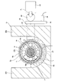
- FIG. 8 shows a radial rolling bearing test apparatus in the second conventional example.
- the fixed housing 1a has a rectangular box shape with an open top, and a pair of side plate portions 9 and 9 parallel to each other and a pair of end plates that connect the end portions of the side plate portions 9 and 9 to a flat bottom plate portion 8. Each part is supported and fixed by welding or the like.
- the inner side of the fixed housing 1a is accompanied with the rotation (revolution) of the balls 10 and 10 of the radial rolling bearing 3a.
- a flow in the same direction as the rotational direction of the balls 10 and 10 is induced in the lubricating oil in the lubricating oil reservoir 6a provided on the surface.
- the retention of lubricating oil is likely to occur at the corner (the portion surrounded by the chain line ⁇ in FIG. 8) near the boundary between the upper surface of the bottom plate 8 and the inner surface of the side plates 9, 9. .
- the properties of the lubricating oil may become non-uniform in the lubricating oil reservoir 6a.
- the foreign matter 7 or 7 stays in the corner and cannot be properly fed into the load zone of the radial rolling bearing 3a as the test bearing. May not be able to perform high-level tests.
- the object of the present invention is to provide a test apparatus for a radial rolling bearing capable of performing a highly reliable test.
- the test apparatus for radial rolling bearing of the present invention is used for evaluating the durability (life test) of the radial rolling bearing.
- a radial rolling bearing to be subjected to a life test includes an outer ring, an inner ring, and a plurality of rolling elements.
- the outer ring has an inner peripheral surface on which an outer ring raceway is formed.
- the inner ring has an outer peripheral surface on which an inner ring raceway is formed.
- the rolling element is provided between the outer ring raceway and the inner ring raceway so as to roll freely.
- the radial rolling bearing test apparatus includes a rotating shaft, a lubricating oil reservoir, a rotation driving unit, and a load applying unit.
- An inner ring of a radial rolling bearing which is a test bearing is fitted on the rotating shaft.
- the rotational drive unit is configured to rotationally drive the rotational shaft.
- the lubricating oil reservoir is configured to store lubricating oil that immerses a part of the radial rolling bearing.
- the load application unit is configured to apply a radial load to the radial rolling bearing.
- the bottom surface of the lubricating oil reservoir has a partially cylindrical concave curved surface concentric with the central axis of the rotating shaft (central axis of the radial rolling bearing).
- the curvature radius of the bottom surface of the lubricating oil reservoir is preferably 0.6 times or more and 2 times or less of the outer diameter of the radial rolling bearing, and more preferably less than or equal to the outer diameter of the radial rolling bearing.
- the oil surface (upper surface) of the lubricating oil may be positioned on the central axis of the rotation shaft before the rotation shaft is rotationally driven.
- the radial rolling bearing test apparatus may further include a heater configured to keep the temperature of the lubricating oil at a desired temperature and a support sleeve in which the radial rolling bearing is fitted.
- the heater is provided between the outer peripheral surface of the bottom surface support sleeve of the lubricating oil reservoir.
- the heater is provided with a gap interposed between the lower surface of the heater and the bottom surface of the lubricating oil reservoir, and between the upper surface of the heater and the outer peripheral surface of the support sleeve.
- the heater may be curved along the bottom surface of the lubricating oil reservoir.
- the load applying unit applies a radial load in the horizontal direction.
- a radial rolling bearing test device includes a housing, a rotating shaft, a rotation driving unit, and a load applying unit.
- a rotating shaft is rotatably supported inside the housing, and an inner ring of the radial rolling bearing is fitted on the outer side.
- the rotational drive unit is configured to rotationally drive the rotational shaft.
- the load application unit is configured to apply a radial load to the radial rolling bearing.
- the housing is not formed by connecting (fixing) a plurality of members, but the whole is integrally formed.
- the housing is made of carbon steel, for example. This housing is manufactured by forging a material made of carbon steel and further performing cutting as necessary.
- a lubricating oil sump configured to store lubricating oil that immerses a part of the radial rolling bearing may be provided inside the housing.
- the load applying unit may apply a radial load in the horizontal direction.
- the bottom surface of the lubricating oil reservoir may have a partially cylindrical concave curved surface concentric with the central axis of the rotating shaft.
- the curvature radius of the bottom surface of the lubricating oil reservoir is preferably 0.6 times or more and 2 times or less of the outer diameter of the radial rolling bearing, and more preferably less than or equal to the outer diameter of the radial rolling bearing.
- Foreign materials such as metal powder and ceramic powder may be mixed in the lubricating oil.
- the bottom surface of the lubricating oil reservoir that stores the lubricating oil has a partially cylindrical concave curved surface that is concentric with the central axis of the rotating shaft, so that the lubricating oil stays in the lubricating oil reservoir. Can be prevented. For this reason, lubricating oil can be circulated. Therefore, the properties of the lubricating oil can be made uniform throughout the lubricating oil reservoir. Thereby, it becomes possible to perform highly reliable evaluation regarding the lifetime of a radial rolling bearing.
- the rigidity of the housing can be sufficiently increased, and a radial load can be normally applied to the radial rolling bearing as the test bearing.
- variations in test results can be suppressed, and a highly reliable evaluation can be performed regarding the life of the radial rolling bearing.
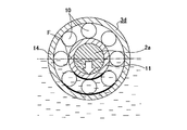
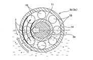
- FIG. 2 is a schematic diagram including a cross-sectional view taken along line II-II in FIG. 1.
- FIG. 8 is a cross-sectional view of a radial rolling bearing test apparatus in a second conventional example corresponding to a cross section taken along line VIII-VIII in FIG.
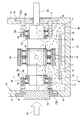
- FIG. 1 to 3B show a radial rolling bearing test apparatus according to an embodiment of the present invention.
- the distal end portion and the proximal end portion of the rotating shaft 2a are rotatably supported by a pair of radial rolling bearings 3b and 3c, each of which is a test bearing, with respect to the fixed housing 1b.
- the inner rings 11, 11 of the radial rolling bearings 3b, 3c are externally fitted to the distal end portion and the proximal end portion of the rotating shaft 2a.
- the inner surfaces of the inner rings 11, 11 are abutted against step portions 12, 12 provided at the intermediate portion of the rotating shaft 2 a via washers 13, 13.
- the outer rings 14 and 14 of the radial rolling bearings 3b and 3c are supported by a pair of axial side wall portions 15 and 15 of a fixed housing 1b that is vertically arranged in a state of being separated in the axial direction of the rotary shaft 2a.
- the substantially cylindrical support sleeves 17a and 17b are attached inside the circular holes 16 and 16 provided in the axial side wall portions 15 and 15, respectively.
- wheel 14 and 14 is internally fitted by cylindrical-surface-shaped support part 18a, 18b provided in the internal peripheral surface of the front-end
- the outer surface of the outer ring 14 of the radial rolling bearing 3b is abutted against a step surface provided at the inner end of the support portion 18a of the support sleeve 17a. Thereby, the radial rolling bearing 3b is strongly clamped in the axial direction between the outer surface of the washer 13 and the stepped surface of the support portion 18a of the support sleeve 17a.
- the outer surface of the outer ring 14 of the other radial rolling bearing 3c abuts against the tip surface of the piston portion 19 that is inserted (inserted) into the inner side of the other support sleeve 17b so as to be axially displaceable.
- the radial rolling bearing 3 c is strongly held in the axial direction between the outer surface of the washer 13 and the tip surface of the piston portion 19.
- the axial load Fa of a desired value can be applied to the radial rolling bearings 3b and 3c by pressing the base end surface of the piston portion 19 with a pressurizing device such as a hydraulic cylinder (not shown).
- a substantially cylindrical movable housing 4a is disposed concentrically with the rotating shaft 2a around the middle portion of the rotating shaft 2a.
- a pair of support bearings 5a and 5a are provided between the inner peripheral surface of the movable housing 4a and the outer peripheral surface of the intermediate portion of the rotating shaft 2a.
- the movable housing 4a is provided inside the fixed housing 1b in a state that allows radial displacement and prevents rotational displacement. In this example, a desired radial load Fr can be applied to the movable housing 4a in the horizontal direction.
- the vibrations of the radial rolling bearings 3b and 3c can be detected via the members 2a, 5a, 4a and 22 respectively. It is said.
- Rotation for rotating the rotation shaft 2a at a desired rotation speed by connecting the rotation shaft 2a to an output shaft of a drive source such as an electric motor directly or via a pulley and coupling over which an endless belt is stretched.
- a drive source such as an electric motor directly or via a pulley and coupling over which an endless belt is stretched.
- the drive part is comprised.
- the fixed housing 1b is formed in a substantially rectangular box shape having an upper opening, and is formed integrally by forging and cutting a carbon steel material. is doing.
- a lubricating oil reservoir 6b is provided inside the fixed housing 1b, and the bottom surface of the lubricating oil reservoir 6b is a partially cylindrical concave curved surface concentric with the rotating shaft 2a.
- the curvature radius r of the bottom surface of the lubricating oil reservoir 6b is not less than 0.6 times and not more than 2 times (0.6D ⁇ r ⁇ 2D), preferably not more than the outer diameter D, of the outer diameter D of the radial rolling bearings 3b, 3c. Yes.
- a heater 27 is provided at the bottom of the lubricating oil reservoir 6b that is always immersed in the lubricating oil. Specifically, a plate-like heater 27 is provided between the bottom surface of the lubricating oil reservoir 6b and the outer peripheral surfaces of the movable housing 4a and the support sleeves 17a and 17b. Gaps are interposed between the lower surface of the heater 27 and the bottom surface of the lubricating oil reservoir 6b, and between the upper surface of the heater 27 and the outer peripheral surfaces of the movable housing 4a and the support sleeves 17a and 17b. The heater 27 is curved along the bottom surface of the lubricating oil reservoir 6b.
- the lubricating oil reservoir 6b stores lubricating oil mixed with foreign substances 7, 7 such as metal powder and ceramic powder at a desired ratio. For this reason, the mixing rate of the foreign substances 7 and 7 in the lubricating oil does not change during the period from the start of the experiment to the end of the experiment. Then, as the rotary shaft 2a, and thus the radial rolling bearings 3a and 3b and the support bearings 5a and 5a rotate, the lubricating oil is agitated and the foreign matters 7 and 7 are uniformly dispersed in the lubricating oil.
- a rectifying means for making the flow of the lubricating oil in the lubricating oil reservoir 6b appropriate.
- the stirring effect by the rotating shaft 2a and the lubricity of the load zone are taken into consideration.
- the lubricating oil is stored so that the oil level is located on the central axis of the rotating shaft 2a. And in the state before rotating the rotating shaft 2a, only the lower half part of the radial rolling bearings 3b and 3c is immersed in lubricating oil.
- the radial rolling bearings 3b and 3c are immersed in the lubricating oil at least one third from the lower end in the radial direction. I try to be in the state.
- the heater 27 holds the lubricating oil at a desired temperature (for example, 100 ° C.).
- a desired temperature for example, 100 ° C.
- the rotary shaft 2a is pressed in the axial direction by pressing the base end face of the piston portion 19, and a desired axial load Fa is applied to the radial rolling bearings 3b and 3c. Further, by pressing the outer peripheral surface of the movable housing 4a with the pressing rod 23, the rotating shaft 2a is pressed in the horizontal direction, and a desired radial load Fr is applied to the radial rolling bearings 3b and 3c. In this state, the rotation shaft 2a is a load in which the rotation (revolution) direction of the balls 10 and 10 of the radial rolling bearings 3b and 3c is located in front of the radial direction of the radial rolling bearings 3b and 3c in the acting direction of the radial load Fr.
- the vibration value (amplitude) of the radial rolling bearings 3b and 3c detected by the vibration sensor 26 is set to be 1.5 times or more and less than 3 times (for example, 2 times) the initial vibration value at the start of the test.
- the time when the threshold value is exceeded is regarded as the life of the radial rolling bearings 3b and 3c, and the test is terminated.
- the test may be terminated by vibration based on breakage other than the radial rolling bearings 3b and 3c.
- the threshold is 3 times or more, the breakage is greatly advanced, and there is a possibility that the site where the breakage has started cannot be specified.
- the radial rolling bearings 3b and 3c are exchanged from both axial sides of the rotary shaft 2a with the support sleeves 17a and 17b displaced outward in the axial direction.
- the lubricating oil is prevented from staying in the lubricating oil reservoir 6b, and the properties of the lubricating oil are changed to the lubricating oil reservoir 6b.
- the bottom surface of the lubricating oil reservoir 6b is a partially cylindrical concave curved surface concentric with the central axis of the rotating shaft 2a, so that it is mixed in the lubricating oil or lubricating oil in the lubricating oil reservoir 6b. It is possible to prevent the foreign substances 7 and 7 having various sizes from staying (depositing).
- Lubricating oil and foreign substances 7 and 7 mixed in the lubricating oil are likely to stay in the nearby corner (the part surrounded by the chain line ⁇ in FIG. 6).
- the bottom surface of the lubricating oil reservoir 6b is formed as a partially cylindrical concave curved surface, thereby preventing the lubricating oil and foreign substances 7 and 7 from staying.
- the heater 27 is provided between the bottom surface of the lubricating oil reservoir 6b and the outer peripheral surfaces of the movable housing 4a and the support sleeves 17a and 17b, and a gap is provided between each surface and the upper and lower surfaces of the heater 27. It is provided in an intervening state. For this reason, the flow rate of the lubricating oil can be increased on both the upper and lower sides of the heater 27 based on the restriction of the flow path, and the lubricating oil and the foreign matters 7 and 7 can be more difficult to stay. Heat exchange with lubricating oil can be performed efficiently.
- the radius of curvature r of the bottom surface of the lubricating oil reservoir 6a is 0.6 times or more and 2 times or less the outer diameter D of the radial rolling bearings 3b and 3c (0.6D ⁇ r ⁇ 2D). Therefore, the circulation property of the lubricating oil can be improved without increasing the amount of the required lubricating oil. Furthermore, if the curvature radius r is set to the outer diameter D or less (r ⁇ D), the amount of lubricating oil can be further reduced. That is, when the curvature radius r is larger than twice the outer diameter D (r> 2D), the required amount of lubricating oil increases.
- the clearance between the upper and lower sides of the heater 27 becomes too narrow, and the circulation of the lubricating oil decreases.
- the contact area between the upper and lower surfaces of the heater 27 and the lubricating oil can be increased, and the oil temperature of the lubricating oil can be adjusted efficiently.
- the bottom surface of the lubricating oil reservoir 6b is a concave curved surface and the surface of the lubricating oil reservoir 6b is smoothly continuous, the surface of the lubricating oil reservoir 6b can absorb or dissipate heat uniformly and prevent variations in oil temperature. .
- the oil temperature of the lubricating oil stored in the lubricating oil reservoir 6a can be adjusted within a desired temperature range of ⁇ 3 ° C.
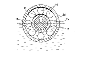
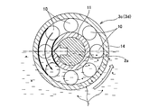
- FIGS. 4A to 5B show a structure in which a radial load is applied in the vertical direction to the radial rolling bearing 3d, which is a test bearing, as in the conventional example described above.
- the radial rolling bearing 3d which is a test bearing, as in the conventional example described above.
- the radial rolling bearing 3d Since the radial rolling bearing 3d has its lower half immersed in lubricating oil, the lubrication state in the load zone becomes excessive (becomes too good), and the test time increases.
- the support bearing 5 (see FIG. 7) has a load zone at the upper end, and the lubricating oil in the load zone tends to be insufficient or depleted. As a result, the life of the support bearing 5 is shortened, and the support bearing 5 needs to be frequently replaced. There is a possibility that the life of the support bearing 5 becomes shorter than the life of the radial rolling bearing 3d, and the life test of the radial rolling bearing 3d cannot be normally performed.
- FIG. 4 As shown in FIG. 4, a flow from the bottom of the lubricating oil reservoir 6b toward the load zone can be induced in the lubricating oil. As a result, a part of the lubricating oil can be splashed even on the part of the load zone that is not immersed in the lubricating oil, so that the lubricating oil can be properly distributed and a stable test can be performed. It becomes possible to do.
- the foreign substances 7 and 7 mixed in the lubricating oil can be appropriately fed into the load zone.
- the temperature change of the members disposed inside the fixed housing 1b such as the radial rolling bearings 3b and 3c and the rotating shaft 2a is suppressed. it can.
- the fixed housing 1c has a rectangular box shape with an open top, and a flat bottom plate portion 8a, a pair of side plate portions 9a, 9a parallel to each other, and a side plate portion 9a, It is constructed by supporting and fixing a pair of end plate portions connecting the end portions of 9a by welding or the like. That is, the fixed housing 1b is made by connecting five plate members.
- the radial load Fr cannot be normally applied to the radial rolling bearings 3b and 3c, and the variation in test results may increase.
- the fixed housing 1b is integrally formed as a whole, and the rigidity against the radial load Fr is increased.
- the radial load Fr is normally applied to the radial rolling bearings 3b and 3c, and the test is performed. Variation in results can be prevented.
- the fixed housing 1b is integrally formed as a whole, and the bottom surface of the lubricating oil reservoir 6b is formed as a concave curved surface, and the plate thickness of the width direction side wall portions 17a, 17b is larger on the lower end side than the upper end. The rigidity against Fr can be further increased. Since there is no seam formed by combining a plurality of plate materials on the inner surface of the lubricating oil reservoir 6b, heat transfer can be improved.
- the vibration sensor 26 is provided with a pressing plate 25 provided between the proximal end surface of the pressing jig 22 whose front end surface is in contact with the movable housing 4 a and the steel ball 24 pressed by the pressing rod 23. It is installed in. That is, since the vibration sensor 26 is provided so as to detect the vibration of the pressing plate 25 provided in series with respect to the acting direction of the radial load Fr, the detection accuracy of the vibrations of the radial rolling bearings 3b and 3c is improved. Further, the proximal end surface of the pressing jig 22 and the pressing plate 25 are brought into surface contact. From this aspect, the vibration detection accuracy can be improved. Since the vibration sensor 26 is provided outside the fixed housing 1 b, it is possible to prevent the vibration sensor 26 from being splashed with lubricating oil or being heated to a high temperature by the heat generated by the heater 27.
- the rotation direction of the rotating shaft is the direction in which the rolling element of the test bearing passes through the load zone from the lower side to the upper side in the example and the comparative example 2, and the rolling element is loaded in the comparative example 1.
- the direction is to pass from above to below.
- Test temperature 100 ° C
- Lubricating oil Transmission oil
- Foreign matter Mixing a predetermined amount of iron-based metal powder
- the life of the test bearing the time when the vibration value of the test bearing detected by the vibration sensor was twice the initial vibration value was defined as the life of the test bearing. At that time, the test was terminated, and the presence or absence of peeling of the inner ring raceway and the outer ring raceway and the rolling surface of each rolling element was visually confirmed. The longest test time was 500 hours (Hr), and for the test bearings in which the vibration value did not reach twice the initial vibration value after 500 hours had elapsed, the subsequent tests were aborted. Table 1 shows the results of the life test.
- the radial load cannot be normally applied to the test bearing.
- the cut-off time exceeded 40% of the test bearings.
- the difference between the maximum value and the minimum value of the lifetime is as small as 1.6 times, and the value of the Weibull slope is as high as 6.3.
- the damaged part is an inner ring or an inner / outer ring.
- the present invention is based on Japanese Patent Application No. 2013-077989 filed on April 5, 2013 and Japanese Patent Application No. 2013-079790 filed on April 5, 2013, the contents of which are incorporated herein by reference.
Landscapes
- Physics & Mathematics (AREA)
- General Physics & Mathematics (AREA)
- Acoustics & Sound (AREA)
- General Health & Medical Sciences (AREA)
- Life Sciences & Earth Sciences (AREA)
- Chemical & Material Sciences (AREA)
- Analytical Chemistry (AREA)
- Biochemistry (AREA)
- Health & Medical Sciences (AREA)
- Immunology (AREA)
- Pathology (AREA)
- Testing Of Devices, Machine Parts, Or Other Structures Thereof (AREA)
- Rolling Contact Bearings (AREA)
- Engineering & Computer Science (AREA)
- General Engineering & Computer Science (AREA)
- Mechanical Engineering (AREA)
Abstract
Description
供試軸受 : 呼び番号6208(外径=80mm、内径=40mm、幅=18mm)
試験荷重 : 7300N{P/C(負荷荷重/定格荷重)=0.25}
回転速度 : 4500min-1
試験温度 : 100℃
潤滑油 : トランスミッション油
異物 : 鉄系金属粉末を所定量混入

2、2a 回転軸
3、3a~3d ラジアル転がり軸受
6、6a、6b 潤滑油溜り
7 異物
10 玉
11 内輪
14 外輪
17a、17b 支持スリーブ
22 押圧治具
23 押圧ロッド
24 鋼球
25 押圧板
27 ヒータ
Claims (13)
- 外輪軌道が形成された内周面を有する外輪と、内輪軌道が形成された外周面を有する内輪と、前記外輪軌道と前記内輪軌道との間に転動自在に設けられた複数の転動体とを備えたラジアル転がり軸受の軸受寿命の試験を行う為のラジアル転がり軸受用試験装置であって、
前記ラジアル転がり軸受の内輪が外嵌される回転軸と、
前記回転軸を回転駆動する回転駆動部と、
前記ラジアル転がり軸受の一部を浸漬させる潤滑油を貯留するように構成された潤滑油溜りと、
前記ラジアル転がり軸受にラジアル荷重を付与するように構成された荷重付与部と、を備え、
前記潤滑油溜りの底面は、前記回転軸の中心軸と同心の部分円筒状の凹曲面を有する、ラジアル転がり軸受用試験装置。 - 前記潤滑油溜りの底面の曲率半径が、前記ラジアル転がり軸受の外径の0.6倍以上、2倍以下である、請求項1に記載したラジアル転がり軸受用試験装置。
- 前記回転軸を回転駆動する以前の状態で、前記潤滑油の油面を、前記回転軸の中心軸上に位置させている、請求項1又は2に記載したラジアル転がり軸受用試験装置。
- 前記潤滑油の油温を所望の温度に保持するように構成されたヒータと、
前記ラジアル転がり軸受が内嵌される支持スリーブと、を更に備え、
前記ヒータは、前記潤滑油溜りの底面と前記支持スリーブの外周面との間に設けられ、前記ヒータの下面と前記潤滑油溜りの底面との間、及び前記ヒータの上面と前記支持スリーブの外周面との間に隙間を介在させている、請求項1~3の何れか1項に記載したラジアル転がり軸受用試験装置。 - 前記ヒータが、前記潤滑油溜りの底面に沿って湾曲している、請求項4に記載したラジアル転がり軸受用試験装置。
- 前記潤滑油中に異物を混入している、請求項1~5の何れか1項に記載したラジアル転がり軸受用試験装置。
- 前記荷重付与部が、水平方向にラジアル荷重を付与する、請求項1~6の何れか1項に記載したラジアル転がり軸受用試験装置。
- 外輪軌道が形成された内周面を有する外輪と、内輪軌道が形成された外周面を有する内輪と、前記外輪軌道と前記内輪軌道との間に転動自在に設けられた複数の転動体とを備えたラジアル転がり軸受の軸受寿命の試験を行う為のラジアル転がり軸受用試験装置であって、
ハウジングと、
前記ハウジングの内側に回転自在に支持され、前記ラジアル転がり軸受の内輪が外嵌される回転軸と、
前記回転軸を回転駆動するように構成された回転駆動部と、
ラジアル転がり軸受にラジアル荷重を付与するように構成された荷重付与部と、を備え、
前記ハウジングは、全体が一体に形成されている、ラジアル転がり軸受用試験装置。 - 前記ハウジングが炭素鋼製である、請求項8に記載したラジアル転がり軸受用試験装置。
- 前記ハウジングの内側に、前記ラジアル転がり軸受の一部を浸漬する潤滑油を貯留するように構成された潤滑油溜りが設けられ、前記荷重付与部が、水平方向にラジアル荷重を付与する、請求項8又は9に記載したラジアル転がり軸受用試験装置。
- 前記潤滑油溜りの底面が、前記回転軸の中心軸と同心の部分円筒状の凹曲面を有する、請求項10に記載したラジアル転がり軸受用試験装置。
- 前記潤滑油溜りの底面の曲率半径が、前記ラジアル転がり軸受の外径の0.6倍以上、2倍以下である、請求項11に記載したラジアル転がり軸受用試験装置。
- 前記潤滑油中に異物を混入している、請求項10~12の何れか1項に記載したラジアル転がり軸受用試験装置。
Priority Applications (4)
| Application Number | Priority Date | Filing Date | Title |
|---|---|---|---|
| KR1020157027077A KR101772307B1 (ko) | 2013-04-05 | 2014-04-04 | 래디얼 롤링 베어링용 시험 장치 |
| US14/781,954 US9903786B2 (en) | 2013-04-05 | 2014-04-04 | Radial rolling-bearing testing device |
| CN201480020060.8A CN105102955B (zh) | 2013-04-05 | 2014-04-04 | 向心滚动轴承用试验装置 |
| EP14779473.9A EP2982955B1 (en) | 2013-04-05 | 2014-04-04 | Radial-rolling-bearing testing device |
Applications Claiming Priority (4)
| Application Number | Priority Date | Filing Date | Title |
|---|---|---|---|
| JP2013-079789 | 2013-04-05 | ||
| JP2013079789A JP6205801B2 (ja) | 2013-04-05 | 2013-04-05 | ラジアル転がり軸受用試験装置 |
| JP2013-079790 | 2013-04-05 | ||
| JP2013079790A JP6205802B2 (ja) | 2013-04-05 | 2013-04-05 | ラジアル転がり軸受用試験装置 |
Publications (1)
| Publication Number | Publication Date |
|---|---|
| WO2014163193A1 true WO2014163193A1 (ja) | 2014-10-09 |
Family
ID=51658480
Family Applications (1)
| Application Number | Title | Priority Date | Filing Date |
|---|---|---|---|
| PCT/JP2014/060003 Ceased WO2014163193A1 (ja) | 2013-04-05 | 2014-04-04 | ラジアル転がり軸受用試験装置 |
Country Status (5)
| Country | Link |
|---|---|
| US (1) | US9903786B2 (ja) |
| EP (1) | EP2982955B1 (ja) |
| KR (1) | KR101772307B1 (ja) |
| CN (1) | CN105102955B (ja) |
| WO (1) | WO2014163193A1 (ja) |
Cited By (3)
| Publication number | Priority date | Publication date | Assignee | Title |
|---|---|---|---|---|
| JP2014202639A (ja) * | 2013-04-05 | 2014-10-27 | 日本精工株式会社 | ラジアル転がり軸受用試験装置 |
| JP2014202638A (ja) * | 2013-04-05 | 2014-10-27 | 日本精工株式会社 | ラジアル転がり軸受用試験装置 |
| CN115078147A (zh) * | 2022-06-01 | 2022-09-20 | 一汽解放汽车有限公司 | 检测系统 |
Citations (5)
| Publication number | Priority date | Publication date | Assignee | Title |
|---|---|---|---|---|
| JPS61163946U (ja) * | 1985-03-30 | 1986-10-11 | ||
| JPH08141380A (ja) * | 1994-11-17 | 1996-06-04 | Nippon Seiko Kk | 潤滑油中の異物を攪拌する装置 |
| JP3018355B2 (ja) * | 1989-10-11 | 2000-03-13 | 日本精工株式会社 | 軸受用鋼及び転がり軸受 |
| JP3448998B2 (ja) * | 1994-12-14 | 2003-09-22 | 日本精工株式会社 | 転がり軸受用回転試験装置 |
| JP2007003196A (ja) | 2005-06-21 | 2007-01-11 | Nsk Ltd | 異物混入下による転がり軸受の寿命試験装置 |
Family Cites Families (7)
| Publication number | Priority date | Publication date | Assignee | Title |
|---|---|---|---|---|
| US5298323A (en) | 1989-10-11 | 1994-03-29 | Nippon Seiko Kabushiki Kaisha | Bearing steel and rolling bearing made thereof |
| JP3315480B2 (ja) | 1993-07-16 | 2002-08-19 | 三菱電機株式会社 | 軸受装置 |
| JPH0932525A (ja) | 1995-07-24 | 1997-02-04 | Fuji Oozx Inc | エンジンの耐久試験に用いる潤滑油加熱装置 |
| US6550258B1 (en) * | 2000-11-22 | 2003-04-22 | Carrier Corporation | Pre-start bearing lubrication for refrigeration system compressor |
| JP2005106479A (ja) * | 2003-09-26 | 2005-04-21 | Honda Motor Co Ltd | 摩耗試験装置 |
| ES2420154T3 (es) * | 2010-05-06 | 2013-08-22 | Moventas Gears Oy | Dispositivo electromecánico |
| US9335317B2 (en) * | 2011-03-03 | 2016-05-10 | Ntn Corporation | Status monitoring system and status monitoring method for rolling device |
-
2014
- 2014-04-04 KR KR1020157027077A patent/KR101772307B1/ko not_active Expired - Fee Related
- 2014-04-04 WO PCT/JP2014/060003 patent/WO2014163193A1/ja not_active Ceased
- 2014-04-04 US US14/781,954 patent/US9903786B2/en not_active Expired - Fee Related
- 2014-04-04 CN CN201480020060.8A patent/CN105102955B/zh not_active Expired - Fee Related
- 2014-04-04 EP EP14779473.9A patent/EP2982955B1/en not_active Not-in-force
Patent Citations (5)
| Publication number | Priority date | Publication date | Assignee | Title |
|---|---|---|---|---|
| JPS61163946U (ja) * | 1985-03-30 | 1986-10-11 | ||
| JP3018355B2 (ja) * | 1989-10-11 | 2000-03-13 | 日本精工株式会社 | 軸受用鋼及び転がり軸受 |
| JPH08141380A (ja) * | 1994-11-17 | 1996-06-04 | Nippon Seiko Kk | 潤滑油中の異物を攪拌する装置 |
| JP3448998B2 (ja) * | 1994-12-14 | 2003-09-22 | 日本精工株式会社 | 転がり軸受用回転試験装置 |
| JP2007003196A (ja) | 2005-06-21 | 2007-01-11 | Nsk Ltd | 異物混入下による転がり軸受の寿命試験装置 |
Non-Patent Citations (1)
| Title |
|---|
| See also references of EP2982955A4 |
Cited By (3)
| Publication number | Priority date | Publication date | Assignee | Title |
|---|---|---|---|---|
| JP2014202639A (ja) * | 2013-04-05 | 2014-10-27 | 日本精工株式会社 | ラジアル転がり軸受用試験装置 |
| JP2014202638A (ja) * | 2013-04-05 | 2014-10-27 | 日本精工株式会社 | ラジアル転がり軸受用試験装置 |
| CN115078147A (zh) * | 2022-06-01 | 2022-09-20 | 一汽解放汽车有限公司 | 检测系统 |
Also Published As
| Publication number | Publication date |
|---|---|
| EP2982955B1 (en) | 2017-08-09 |
| EP2982955A4 (en) | 2016-04-20 |
| CN105102955A (zh) | 2015-11-25 |
| EP2982955A1 (en) | 2016-02-10 |
| KR20150121224A (ko) | 2015-10-28 |
| US20160033361A1 (en) | 2016-02-04 |
| US9903786B2 (en) | 2018-02-27 |
| CN105102955B (zh) | 2018-02-13 |
| KR101772307B1 (ko) | 2017-08-28 |
Similar Documents
| Publication | Publication Date | Title |
|---|---|---|
| JP6205800B2 (ja) | ラジアル転がり軸受の寿命試験方法及びラジアル転がり軸受用試験装置 | |
| JP6205803B2 (ja) | ラジアル転がり軸受用試験装置 | |
| CN104747599B (zh) | 滚动轴承以及机床用主轴装置 | |
| CN102472311B (zh) | 具有轴和滚针轴承的轴承系统 | |
| JP6205801B2 (ja) | ラジアル転がり軸受用試験装置 | |
| JP6205802B2 (ja) | ラジアル転がり軸受用試験装置 | |
| Amarnath et al. | Failure analysis of a grease-lubricated cylindrical roller bearing | |
| JP2011196513A (ja) | 転がり軸受 | |
| WO2014163193A1 (ja) | ラジアル転がり軸受用試験装置 | |
| JP2019035756A (ja) | 耐水素性評価試験方法 | |
| EP1260723A2 (en) | Roller bearing having streaked grinding trail on roller end face | |
| JP4730168B2 (ja) | ラジアル転がり軸受の試験方法 | |
| Biswas et al. | An analytical and experimental approach for pressure distribution analysis of a particular lobe and plain bearing performance keeping in view of all impeding varying parameters associating with fixed lubrication SAE20W40 | |
| CN100507298C (zh) | 滚动轴承 | |
| Singla et al. | Experimental evaluation of lubricating oil film pressure and temperarture of elliptical non-circular journal bearing profile | |
| JP2005226682A (ja) | ころ軸受 | |
| JP2015200355A (ja) | 転がり軸受 |
Legal Events
| Date | Code | Title | Description |
|---|---|---|---|
| WWE | Wipo information: entry into national phase |
Ref document number: 201480020060.8 Country of ref document: CN |
|
| 121 | Ep: the epo has been informed by wipo that ep was designated in this application |
Ref document number: 14779473 Country of ref document: EP Kind code of ref document: A1 |
|
| REEP | Request for entry into the european phase |
Ref document number: 2014779473 Country of ref document: EP |
|
| WWE | Wipo information: entry into national phase |
Ref document number: 2014779473 Country of ref document: EP |
|
| ENP | Entry into the national phase |
Ref document number: 20157027077 Country of ref document: KR Kind code of ref document: A |
|
| WWE | Wipo information: entry into national phase |
Ref document number: 14781954 Country of ref document: US |
|
| NENP | Non-entry into the national phase |
Ref country code: DE |