WO2014163203A1 - 自動車用構造部材、及びその製造方法 - Google Patents
自動車用構造部材、及びその製造方法 Download PDFInfo
- Publication number
- WO2014163203A1 WO2014163203A1 PCT/JP2014/060025 JP2014060025W WO2014163203A1 WO 2014163203 A1 WO2014163203 A1 WO 2014163203A1 JP 2014060025 W JP2014060025 W JP 2014060025W WO 2014163203 A1 WO2014163203 A1 WO 2014163203A1
- Authority
- WO
- WIPO (PCT)
- Prior art keywords
- welding
- component member
- structural member
- component
- vertical wall
- Prior art date
- Legal status (The legal status is an assumption and is not a legal conclusion. Google has not performed a legal analysis and makes no representation as to the accuracy of the status listed.)
- Ceased
Links
Images


Classifications
-
- B—PERFORMING OPERATIONS; TRANSPORTING
- B62—LAND VEHICLES FOR TRAVELLING OTHERWISE THAN ON RAILS
- B62D—MOTOR VEHICLES; TRAILERS
- B62D21/00—Understructures, i.e. chassis frame on which a vehicle body may be mounted
- B62D21/15—Understructures, i.e. chassis frame on which a vehicle body may be mounted having impact absorbing means, e.g. a frame designed to permanently or temporarily change shape or dimension upon impact with another body
-
- B—PERFORMING OPERATIONS; TRANSPORTING
- B62—LAND VEHICLES FOR TRAVELLING OTHERWISE THAN ON RAILS
- B62D—MOTOR VEHICLES; TRAILERS
- B62D25/00—Superstructure or monocoque structure sub-units; Parts or details thereof not otherwise provided for
-
- B—PERFORMING OPERATIONS; TRANSPORTING
- B21—MECHANICAL METAL-WORKING WITHOUT ESSENTIALLY REMOVING MATERIAL; PUNCHING METAL
- B21D—WORKING OR PROCESSING OF SHEET METAL OR METAL TUBES, RODS OR PROFILES WITHOUT ESSENTIALLY REMOVING MATERIAL; PUNCHING METAL
- B21D7/00—Bending rods, profiles, or tubes
-
- B—PERFORMING OPERATIONS; TRANSPORTING
- B23—MACHINE TOOLS; METAL-WORKING NOT OTHERWISE PROVIDED FOR
- B23K—SOLDERING OR UNSOLDERING; WELDING; CLADDING OR PLATING BY SOLDERING OR WELDING; CUTTING BY APPLYING HEAT LOCALLY, e.g. FLAME CUTTING; WORKING BY LASER BEAM
- B23K26/00—Working by laser beam, e.g. welding, cutting or boring
- B23K26/20—Bonding
- B23K26/21—Bonding by welding
- B23K26/22—Spot welding
-
- B—PERFORMING OPERATIONS; TRANSPORTING
- B23—MACHINE TOOLS; METAL-WORKING NOT OTHERWISE PROVIDED FOR
- B23K—SOLDERING OR UNSOLDERING; WELDING; CLADDING OR PLATING BY SOLDERING OR WELDING; CUTTING BY APPLYING HEAT LOCALLY, e.g. FLAME CUTTING; WORKING BY LASER BEAM
- B23K31/00—Processes relevant to this subclass, specially adapted for particular articles or purposes, but not covered by any single one of main groups B23K1/00 - B23K28/00
- B23K31/02—Processes relevant to this subclass, specially adapted for particular articles or purposes, but not covered by any single one of main groups B23K1/00 - B23K28/00 relating to soldering or welding
-
- B—PERFORMING OPERATIONS; TRANSPORTING
- B60—VEHICLES IN GENERAL
- B60R—VEHICLES, VEHICLE FITTINGS, OR VEHICLE PARTS, NOT OTHERWISE PROVIDED FOR
- B60R19/00—Wheel guards; Radiator guards, e.g. grilles; Obstruction removers; Fittings damping bouncing force in collisions
- B60R19/02—Bumpers, i.e. impact receiving or absorbing members for protecting vehicles or fending off blows from other vehicles or objects
- B60R19/04—Bumpers, i.e. impact receiving or absorbing members for protecting vehicles or fending off blows from other vehicles or objects formed from more than one section in a side-by-side arrangement
-
- B—PERFORMING OPERATIONS; TRANSPORTING
- B62—LAND VEHICLES FOR TRAVELLING OTHERWISE THAN ON RAILS
- B62D—MOTOR VEHICLES; TRAILERS
- B62D29/00—Superstructures, understructures, or sub-units thereof, characterised by the material thereof
- B62D29/007—Superstructures, understructures, or sub-units thereof, characterised by the material thereof predominantly of special steel or specially treated steel, e.g. stainless steel or locally surface hardened steel
-
- B—PERFORMING OPERATIONS; TRANSPORTING
- B62—LAND VEHICLES FOR TRAVELLING OTHERWISE THAN ON RAILS
- B62D—MOTOR VEHICLES; TRAILERS
- B62D29/00—Superstructures, understructures, or sub-units thereof, characterised by the material thereof
- B62D29/008—Superstructures, understructures, or sub-units thereof, characterised by the material thereof predominantly of light alloys, e.g. extruded
-
- B—PERFORMING OPERATIONS; TRANSPORTING
- B23—MACHINE TOOLS; METAL-WORKING NOT OTHERWISE PROVIDED FOR
- B23K—SOLDERING OR UNSOLDERING; WELDING; CLADDING OR PLATING BY SOLDERING OR WELDING; CUTTING BY APPLYING HEAT LOCALLY, e.g. FLAME CUTTING; WORKING BY LASER BEAM
- B23K2101/00—Articles made by soldering, welding or cutting
- B23K2101/006—Vehicles
-
- B—PERFORMING OPERATIONS; TRANSPORTING
- B62—LAND VEHICLES FOR TRAVELLING OTHERWISE THAN ON RAILS
- B62D—MOTOR VEHICLES; TRAILERS
- B62D25/00—Superstructure or monocoque structure sub-units; Parts or details thereof not otherwise provided for
- B62D25/02—Side panels
- B62D25/025—Side sills thereof
-
- B—PERFORMING OPERATIONS; TRANSPORTING
- B62—LAND VEHICLES FOR TRAVELLING OTHERWISE THAN ON RAILS
- B62D—MOTOR VEHICLES; TRAILERS
- B62D25/00—Superstructure or monocoque structure sub-units; Parts or details thereof not otherwise provided for
- B62D25/04—Door pillars ; windshield pillars
Definitions
- the present invention relates to an automobile structural member constituting an automobile body and a manufacturing method thereof. Specifically, the present invention relates to a structural member for an automobile having a closed cross-sectional shape configured by combining a metal plate such as a thin steel plate, a molded body of a metal plate, and the like, and a manufacturing method thereof.
- These structural members for automobiles are used to ensure a vehicle interior space in the event of a collision and to efficiently transmit the impact load at the time of the collision to other structural members for a vehicle.
- a high three-point bending load is required.
- the automobile structural member itself is required to have excellent shock absorbing performance against three-point bending.
- the three-point bending load and the shock absorption performance with respect to the three-point bending that the structural member for automobile has are collectively referred to as bending crushing performance.
- automobile structural members are strongly required not only for bending crushing performance, but also for lighter weight and smaller cross-section for improving automobile fuel efficiency.
- a structural member for an automobile includes a first constituent member made of a steel plate formed into a cross-sectional hat shape having an outward flange and a closing plate which is a second constituent member made of a steel plate. Is assembled by spot welding as a welding allowance.
- a hat-shaped member having an outward flange is referred to as a hat member. That is, the hat member is connected to two outward flanges, two curved portions connected to the two outward flanges, two vertical wall portions connected to the two curved portions, and two vertical wall portions, respectively. It has a hat-shaped cross-sectional shape composed of one ridge line part and one groove bottom part connecting the two ridge line parts.
- Patent Document 1 C: 0.05 to 0.3% (in the present specification, “%” regarding chemical composition means “mass%” unless otherwise specified), Mn: 0.5 to 3.
- the radius of the curved portion is set to R on at least one of the two surfaces forming the curved portion from the center of the curved portion.
- a (R + 7) mm reference range is set, and one or a plurality of quenching strengthening portions are formed by laser irradiation or high-frequency heating along the curved portion within the reference range, and all the bending of the first component member is formed.
- An automotive structural member that secures an occupancy of 20% or more of the total width of the hardened strengthened portion within the reference range with respect to the total length of the reference range for all the surfaces constituting the portion. According to this structural member for automobiles, it is disclosed that impact crush resistance can be effectively improved by forming a small quench strengthening portion while ensuring good press formability.
- Patent Document 2 discloses a closed cross-sectional shape formed by a first component member and a second component member that are hat members, and the first component member and the second component member are formed by outward flanges.
- An automotive structural member is disclosed that includes a spot welded cylinder and is filled with a resin layer in a region sandwiched between a curved portion adjacent to an outward flange and a second component member. According to this automobile structural member, it is disclosed that it is lightweight and has an excellent bending crush performance.
- Patent Document 3 discloses a structural member for an automobile in which two inward-shaped constituent members are joined to each other with inward flanges of the constituent members by laser welding so that the bottom inner walls face each other. According to such an automobile structural member, it is disclosed that the amount of energy absorption can be increased by changing the bending load characteristics.
- the first component member which is the hat member disclosed in Patent Documents 1 and 2
- the first component member which is the hat member disclosed in Patent Documents 1 and 2
- deformation of the cross-sectional shape of the hat member during impact load loading is suppressed as much as possible. It is important to efficiently transmit the impact load from the constituent member to the vertical wall portion of the first constituent member.
- the impact load input from the closing plate side is directed outward of the first component member. It is transmitted to the vertical wall portion via a curved portion that inevitably exists between the flange and the vertical wall portion. Therefore, the vertical wall portion is easily buckled and deformed early, and the impact load cannot be efficiently transmitted to the vertical wall portion of the first component member. That is, in order to improve the bending crushing performance of the structural member for automobiles, it is effective to suppress the occurrence of buckling deformation of the vertical wall portion when an impact load is applied.
- Patent Document 1 suppresses deformation of the cross-sectional shape of the hat member by quenching and strengthening the curved portion of the hat member that is the first component member, the vertical wall portion is efficiently Not enough to transmit impact load.
- the invention disclosed in Patent Document 1 requires that the hat member and the closing plate be welded and assembled via the outward flange, and then the laser irradiation and high-frequency induction heating be performed on the bent portion of the hat member. Increases in man-hours and costs required for production are inevitable.
- Patent Document 2 is a modification of the vertical wall portion by filling the region (gap) sandwiched between the curved portion adjacent to the outward flange of the hat member and the second component member. Therefore, the bending crushing performance can be improved to some extent.
- the first component member and the second component member with the outward flange as a welding allowance it is necessary to fill the above-mentioned region with resin, which increases man-hours and costs required for manufacturing. I cannot deny.
- an outward flange having a width of usually about 20 to 30 mm. Must be provided on the first component as a welding allowance. Since the contribution of the outward flange to the bending crushing performance is small, it is desirable to reduce the weight and reduce the cross-section by reducing the width of the outward flange. However, in any invention disclosed in Patent Documents 1 and 2, the outward It is not possible to reduce the weight and size by reducing the flange width.
- the invention disclosed in Patent Document 3 can reduce the weight and the cross section of the structural member for an automobile as compared with the outward flange by joining the inward flanges.
- the inward flanges are joined by laser welding which is welded by melting the interface, a gap is formed in the region sandwiched between the curved portions adjacent to the inward flange. Therefore, when an impact load is transmitted from the other component member to the one component member, the impact load input from the other component member side is a bend between the inward flange and the vertical wall portion of the one component member. It is transmitted to the vertical wall portion through the portion.
- Spot welding can efficiently and easily weld a plurality of thin steel plates stacked in a very short welding time of about 0.1 to 0.5 seconds, so far, especially for structural members for automobiles and automobile bodies. Has been widely used. For this reason, when assembling the automobile structural member by welding the first structural member and the second structural member, an outward flange serving as a welding allowance is formed on the first structural member, and this outward flange is used. It was common knowledge of those skilled in the art to spot weld the second component.
- the present inventors formed an inward flange instead of an outward flange on the first component member, and the first component member was formed via the inward flange. And the second component member are overlapped, and the region between the curved portion continuous to the inward flange and the second component member and extending the vertical wall portion toward the second component member A load transmitting portion that joins the curved portion and the second component member is formed in at least a part of the region. Therefore, it has been found that the number of man-hours and costs required for manufacturing can be reduced to the same level as conventional automotive structural members, and the bending crushing performance of automotive structural members can be significantly improved over that of conventional automotive structural members. The present invention was completed through further studies.
- FIG. 1B to FIG. 1D show an example of the cross-sectional shape of the automotive structural member according to the present invention
- FIG. 1B is a diagram showing the periphery of the load transmitting portion in the automotive structural member according to the present invention. 2 will be described below with reference to FIG.
- the automotive structural members 2 to 4 include at least a first component member 12 made of a metal plate molded body and a metal plate or a metal plate molded body and are joined to the first component member 12.
- a load transmitting portion 20 is formed in at least a part of a region where the vertical wall portion 12c extends toward the second component members 13 to 15, and joins the curved portion 12b and the second component members 13 to 15. Characterized by having That.
- the load transmitting portion 20 is a part of the joint portion 21 that fills part or all of the gap 22 formed between the curved portion 12b and the second component members 13 to 15, and the joint portion 21 Is characterized in that the joining width L, which is a range in contact with the second constituent members 13 to 15, is longer than the width WT of the load transmitting portion 20.
- the curved portion 12b is characterized in that the hardness of at least the range where the load transmitting portion 20 contacts is harder than the hardness of the base material of the first component member 12.
- the load transmitting portion 20 is characterized by being intermittently formed along the longitudinal direction of the automobile structural members 2 to 4.
- the first component member 12 has a vertical wall portion 12c, a curved portion 12b connected to the vertical wall portion 12c and bent toward the inside of the closed cross sectional shape, and A method of manufacturing an automotive structural member 2 to 4 having an inward flange 12a connected to a curved portion 12b, wherein the vertical wall portion 12c is secondly connected between the curved portion 12b and the second component members 13 to 15.
- the curved portion 12b and the load transmitting portion 20 for joining the second constituent members 13 to 15 are formed by welding using a filler material in at least a part of the region extending toward the constituent members 13 to 15 It is characterized by doing.
- the load transmitting portion 20 is formed by a plurality of weldings using the filler material. (8) The welding length is different in at least two weldings among the plurality of weldings. (9) The load transmitting portion 20 is a part of the joint portion 21 that fills part or all of the gap formed between the curved portion 12b and the second component members 13 to 15, and the load transmitting portion 20 Is formed by a plurality of times of welding using the filler material, and in the first welding, the width WT of the load transmitting portion 20 is WT ⁇ 0.6 t, and the joint portion 21 is the second constituent members 13 to 15.
- the load transmitting portion 20 is formed intermittently over the longitudinal direction of the automobile structural members 2 to 4. (11) The load transmitting portion 20 is formed by using the filler material by arc welding or laser / arc hybrid welding.
- the first component member 12 includes, for example, a groove bottom portion 12e extending in one direction (a direction perpendicular to the paper surface of FIGS. 1B to 1D) and a width intersecting with the one direction.
- Two ridge line parts 12d, 12d connected to the groove bottom part 12e at both edges in the direction, two vertical wall parts 12c, 12c connected to each of the two ridge line parts 12d, 12d, and these two vertical wall parts 12c, 12c
- the second constituent member 13 may be a flat metal material such as a closing plate as shown in FIG. 1B.
- the second component members 14 and 15 are metal plate molded bodies, for example, molded bodies having a shape having the same cross-sectional shape as the first component member 12 as shown in FIGS. 1C and 1D. Also good.
- the inward flanges 12a and 12a formed on the first component member 12 and the inward flanges 16a and 16a formed on the second component members 14 and 15 may be overlapped.
- the radius of curvature of the curved portion 12b is too large, it is not easy to form the load transmitting portion 20 by a simple means such as arc welding or laser / arc hybrid welding. Is desirable.
- the radius of curvature is too small, it is difficult to mold the first component member 12, so it is desirable that the radius is 2 mm or more.
- the automobile structural members 2 to 4 according to the present invention are used as a skeleton member of an automobile body (body shell) having a monocoque structure.
- the structural members 2 to 4 for automobiles are used for side sills, bumper reinforcements, and center pillars.
- the bending crush performance can be improved over the bending crush performance of the conventional automotive structural member.
- FIG. 1A is a diagram illustrating an example of a cross-sectional shape of a conventional automotive structural member.
- FIG. 1B is a diagram illustrating an example of a cross-sectional shape of the automotive structural member of the first embodiment.
- FIG. 1C is a diagram illustrating an example of a cross-sectional shape of the automotive structural member of the second embodiment.
- FIG. 1D is a diagram illustrating an example of a cross-sectional shape of the automotive structural member of the third embodiment.
- FIG. 2 is a view showing the periphery of the load transmitting portion in the automotive structural member of the present embodiment.
- FIG. 3A is a diagram showing a cross-sectional shape of the automotive structural member of the first comparative example.
- FIG. 3B is a diagram showing a cross-sectional shape of the automotive structural member of the second comparative example.
- FIG. 3C is a diagram showing a cross-sectional shape of the automotive structural member of the present invention.
- FIG. 4 is a graph showing a load-displacement curve when the plate thickness is 2.0 mm and the curvature radius of the curved portion is 6 mm.
- FIG. 5A is a graph showing the maximum bending load-curvature radius of curvature when the plate thickness is 1.2 mm.
- FIG. 5B is a graph showing the maximum bending load and the radius of curvature of the curved portion when the plate thickness is 2.0 mm.
- FIG. 6 is a diagram showing a cross-sectional shape around the inward flange of the automotive structural member.
- FIG. 7A is a graph showing the maximum bending load and the height of the first component when the plate thickness is 1.2 mm.
- FIG. 7B is a graph showing the maximum bending load and the height of the first component when the plate thickness is 2.0 mm.
- FIG. 8A is a perspective view showing an example of an automotive structural member that is intermittently welded.
- FIG. 8B is a perspective view showing an example of a structural member for automobile in which the welding length is changed according to the number of times of welding.
- the automobile structural member according to the present invention is a side sill
- the present invention is not limited to a side sill, and has a closed cross-sectional shape constituted by the above-described first and second constituent members such as a bumper reinforcement and a center pillar.
- the present invention can be applied to an automobile structural member that is assumed to be subjected to a three-point bending load at the time of automobile collision.
- FIG. 1A is a diagram showing an example of a cross-sectional shape of a conventional automotive structural member 1.
- 1B to 1D are views showing examples of the cross-sectional shapes of the automotive structural members 2 to 4 according to the present embodiment.
- FIG. 2 is a figure which shows the periphery of the load transmission part 20 in the structural member 2 for motor vehicles based on this invention.
- FIG. 2 is an enlarged view of part A in FIG. 1B, but the same description applies to FIGS. 1C and 1D.
- the automotive structural member 1 has a first component member 10 and a second component member 11.
- the first component member 10 includes two outward flanges 10a and 10a, two curved portions 10b and 10b connected to the two outward flanges 10a and 10a, respectively, and two connected to the two curved portions 10b and 10b, respectively.
- the first component member 10 includes two outward flanges 10a, 10a, two curved portions 10b, 10b, two vertical wall portions 10c, 10c, two ridge line portions 10d, 10d, and one groove bottom portion 10e. Having a hat-shaped cross-sectional shape.
- the 1st component member 10 is a cross-sectional hat-shaped molded object (hat member) which has the outward flange 10a.
- the second component member 11 is a closing plate and is formed in a flat plate shape.
- the first component member 10 and the second component member 11 are assembled by spot welding using the outward flanges 10a and 10a as welding allowances.
- the second component member 11 may be a cross-sectional hat-shaped molded body (hat member) having an outward flange, like the first component member 10. is there.
- the first component member 10 and the second component member 11 are assembled by spot welding with the respective outward flanges being spot-welded with the respective outward flanges being overlapped.
- the automobile structural member 1 is fixedly supported at two locations on both ends in the longitudinal direction (direction orthogonal to the paper surface of FIG. 1A) to form a side sill that constitutes an automobile body (body shell).
- the automotive structural member 1 has an impact load F from the second component member 11 toward the first component member 10 between two fixed support positions on both ends in the longitudinal direction (direction orthogonal to the paper surface of FIG. 1A). It is a member that is assumed to be loaded.
- the impact load input from the second component member 11 is the outward flange 10a in the first component member 10, 10a, the curved portions 10b and 10b, and the vertical wall portions 10c and 10c are transmitted in this order. That is, since the input impact load is inevitably transmitted to the vertical wall portions 10c and 10c through the curved portions 10b and 10b, the vertical wall portions 10c and 10c are easily buckled and deformed at an early stage. It is difficult to efficiently transmit an impact load to the vertical wall portions 10c and 10c.
- the automobile structural members 2 to 4 include at least the first component member 12, the second component members 13, 14, 15 and the load transmitting portion 20, these will be sequentially described. .
- each of the first component member 12 and the second component members 13, 14, 15 is a formed body formed of, for example, a cold-rolled steel plate, a hot-rolled steel plate, or a plated steel plate, and the steel type of the steel plate
- the strength, thickness, etc. are not limited.
- a 440 to 980 MPa class high tensile steel having a plate thickness of about 1.2 mm to 2.0 mm is used, but a plate thickness of 1.0 mm using a 1180 to 1470 MPa class high tensile steel. You may make it thin.
- the joining portion 21 load transmission portion
- the first component member 12 is formed of a plate member, and includes a groove bottom portion 12e, two ridge line portions 12d and 12d, two vertical wall portions 12c and 12c, two curved portions 12b and 12b, and two Inward flanges 12a and 12a are provided.
- the groove bottom portion 12e extends in one direction (a direction perpendicular to the paper surface of FIGS. 1B to 1D).
- the two ridge line portions 12d and 12d are connected to the groove bottom portion 12e at both edges in the width direction intersecting with the one direction.
- the two vertical wall portions 12c and 12c are connected to the two ridge line portions 12d and 12d, respectively.
- the two bent portions 12b and 12b are connected to the two vertical wall portions 12c and 12c, respectively, and bend toward the inner side of the closed cross-sectional shape.
- the two inward flanges 12a and 12a are connected to the two curved portions 12b and 12b, respectively.
- the boundaries between the vertical wall portions 12c and 12c and the curved portions 12b and 12b, and the boundaries between the curved portions 12b and 12b and the inward flanges 12a and 12a are indicated by two-dot chain lines.
- the first component member 12 includes a groove bottom portion 12e, two ridge line portions 12d and 12d, two vertical wall portions 12c and 12c, two curved portions 12b and 12b, and two inward flanges 12a and 12a. It has the cross-sectional shape comprised by these.
- the first component member 12 includes the vertical wall portions 12c and 12c, the curved portions 12b and 12b, and the inward flanges 12a and 12a connected to the curved portions 12b and 12b.
- the curvature radii of the curved portions 12b and 12b exceed 8 mm, the amount of the gap formed between the curved portions 12b and 12b and the second component member 13 increases. Therefore, when the load transmission part 20 is formed by welding using a filler material such as arc welding or laser / arc hybrid welding described later, it is necessary not only to increase the joining cost but also to increase the amount of the filler material. Therefore, the welding heat input is increased, and the first constituent member 12 and the second constituent members 13 to 15 are likely to be deformed or melted down due to thermal strain. Moreover, when forming the load transmission part 20 by brazing or adhesion
- the curvature radius of a curved part shall mean the curvature radius of an outer curved surface with a large curvature radius among the curved surfaces of the curved part 12b.
- the first component member 12 may be molded by any molding method and is not limited to a specific molding method. However, if the manufacturing cost is high in press forming to form the inward flange 12a, it can be formed using roll forming or a press brake.
- the second component members 13 to 15 are joined to the first component member 12 via the inward flanges 12a and 12a.
- the automobile structural members 2 to 4 have a closed cross-sectional shape constituted by the first component member 12 and the second component members 13 to 15.
- the second component member 13 according to the first embodiment is a plate material such as a closing plate.
- the automotive structural member 2 of the first embodiment is formed such that W2> W1, where the width of the first component 12 is W1 and the width of the second component 13 is W2.
- the 2nd structural members 14 and 15 which concern on 2nd and 3rd embodiment are the molded objects which have the cross-sectional shape similar to the 1st structural member 12, for example.
- the second component members 14 and 15 include a groove bottom portion 16e extending in one direction (a direction orthogonal to the paper surface in FIGS. 1C and 1D) and both edges in the width direction intersecting the one direction. And two ridge line portions 16d and 16d connected to the groove bottom portion 16e, two vertical wall portions 16c and 16c connected to the two ridge line portions 16d and 16d, and the two vertical wall portions 16c and 16c, respectively.
- the automotive structural members 3, 4 are formed by overlapping inward flanges 12 a, 12 a formed on the first component 12 and inward flanges 16 a, 16 a formed on the second component 14, 15. Composed.
- the second component member 14 of the second embodiment has the same cross-sectional shape as the first component member 12.
- the second component member 15 of the third embodiment has a cross-sectional shape in which the groove bottom portion 16e and the inward flanges 16a and 16a are longer in the width direction than the first component member 12. Accordingly, when the width of the first component member 12 is W1, and the width of the second component member 15 is W2, W2> W1 is formed.
- the second constituent members 14 and 15 having the inward flanges 16a and 16a may be formed by any forming method and are not limited to a specific forming method. However, when the manufacturing cost is high in press molding to form the inward flange 16a, it can be molded using roll forming or a press brake.
- the automotive structural members 2 to 4 may further include other structural members other than the first structural member 12 and the second structural members 13, 14, and 15.
- first component member 12 and the second component member are welded to the third component member and the third component member functions as a reinforcement. It's okay.
- the load transmission part 20 which the structural member 2 for motor vehicles of 1st Embodiment has as shown in FIG. 2 is demonstrated, the structural members 3 and 4 for motor vehicles of 2nd and 3rd embodiment are also the same. is there.
- the load transmitting portion 20 is between the curved portion 12 b of the first component member 12 and the second component member 13, and the vertical wall portion 12 c is connected to the second component member 13. It is formed in a part or all of the region extended toward the surface.
- the load transmission unit 20 forms a part of the joint 21 that joins the first component 12 and the second component 13. Therefore, the load transmission part 20 joins the curved part 12b and the 2nd structural member 13 in the said area
- the joint portion 21 is formed by filling part or all of the gap 22 existing between the curved portion 12b and the second component member 13.
- the gap 22 is formed outside the closed cross section formed by the first component member 12 and the second component member 13. Therefore, the joint portion 21 can be easily formed without increasing the assembly process by means of arc welding, laser / arc hybrid welding, and further, brazing, adhesion, and the like.
- the strength of the joint 21 including the load transmitting portion 20 can be adjusted according to the type of the welding wire as the filler material. For example, by using a high-strength wire, the joint 21 can be made stronger than the steel plate strength of the first component member 12 and the steel plate strength of the second component member 13.
- the joining portion 21 including the load transmitting portion 20 is formed using a filler metal by arc welding or laser / arc hybrid welding.
- the joining portion 21 is mainly a weld metal formed by the filler material moving to the gap 22 between the curved portion 12 b and the second component member 13.
- the joining width which is the range in which the joining part 21 is formed in the 2nd structural member 13 is set to L (mm), and the load transmission part 20 to the plate
- the width (hereinafter referred to as load transmission portion width) is WT (mm)
- the width W2 of the second component members 13 and 15 is the same as the automobile structural member 2 shown in FIG. 1B and the automobile structural member 4 shown in FIG. 1D.
- the length is longer than the width W1 of the first component member 12.
- both ends of the second constituent members 13 and 15 in the width direction are located outside both ends of the first constituent member 12 in the width direction.
- the joining width L of the joining part 21 is formed in a divergent shape toward the second component member 13, and the first component member 13 or 15 is used as the first component member.
- the impact load transmitted to the component member 12 can be effectively transmitted to the vertical wall portion 12c.
- the joint portion 21 is the second constituent member even when the joint width L is longer than the curved portion width Wb. It can be formed in a divergent shape toward 13.
- the joining portion 21 can be easily formed by an appropriate construction means such as arc welding, laser / arc hybrid welding, brazing, and adhesion without increasing the assembly process. can do. Therefore, it is easy to form the joint portion 21, and the load transmitting portion 20 can be efficiently formed.
- the impact load transmitted from the second constituent members 13, 14, 15 to the first constituent member 12 is transmitted by the load transmitting portion 20 without going through the curved portion 12b. It can be effectively transmitted to the vertical wall portion 12c. Therefore, the automotive structural members 2 to 4 can greatly improve the bending crush performance of the automotive structural members than the conventional automotive structural members.
- the joining portion 21 for joining the first constituent member 12 and the second constituent members 13, 14, 15 is formed, the overlapping portion of the inward flanges 12 a, 12 a and the second constituent member 13 is formed. In this case, the joint portion may not be formed. Therefore, the width of the inward flanges 12a, 12a does not need to be secured to about 20 to 30 mm as a spot welding allowance as the width of the outward flange of the first component member constituting the conventional automotive structural member.
- the structural members for automobiles 2 to 4 need only have a width (for example, about 5 to 10 mm) that can ensure the accuracy of abutting the first component member 12 and the second component members 13, 14, and 15;
- the weight of the structural member for automobiles can be greatly reduced.
- the joint 21 can be easily formed without increasing the assembly process by appropriate means such as arc welding, laser / arc hybrid welding, and further brazing and bonding. Therefore, the automobile structural members 2 to 4 can suppress the man-hours and costs required for manufacturing to the same extent as those of the conventional automotive structural members.
- the automobile structural members 2 to 4 do not have the outward flange of the conventional automobile structural member, it is possible to reduce the cross section of the conventional automobile structural member.
- the hardness of at least the range in which the load transmitting portion 20 contacts is harder than the hardness of the base material of the first component member.
- the curvature radius of the curved portion 12b is reduced. From the viewpoint of welding conditions, it is conceivable to increase the arc welding voltage, defocus the laser focus, etc. within a range that does not impair the weldability.
- the maximum bending load increases as the load transmitting portion width WT of the load transmitting portion 20 increases.
- the load transmitting portion width WT can be increased by increasing the amount of filler material.
- the amount of the filler material is increased, it is necessary to increase the welding current, and thus the first component member 12 or the second component member may be melted down. Therefore, when forming the joining part 21 including the load transmitting part 20, it is desirable to weld the same part in a plurality of times.
- the amount of welding heat input to the first component member 12 and the second component member for each time can be reduced, and the first component member 12 and the second component member can be reduced. It is possible to prevent the component member 13 from being melted.
- the joint portion 21 including the load transmission portion 20 is formed by welding, thermal distortion occurs in the automobile structural member.
- the thermal strain is large, there is a possibility that a dimensional error may occur with respect to a desired size of the automobile structural member. Therefore, when the thermal strain increases, it is desirable to intermittently weld the entire length of the automobile structural member. By intermittently welding the entire length of the automotive structural members 2 to 4, the influence of thermal strain can be reduced and the occurrence of dimensional errors can be suppressed.
- FIG. 3A is a diagram showing a cross-sectional shape of the automotive structural member 31 of the first comparative example.
- the automotive structural member 31 of the first comparative example was manufactured by spot welding the outward flange 10a of the hat member 10 as the first component and the closing plate 11 as the second component.
- the curvature radius R of the curved portion 10b shown in FIG. 3A is 6 mm.
- Spot welding was performed at a dot pitch of 30 mm for a total length of 600 mm in the longitudinal direction.
- the welding conditions were a pressure of 3920 N, the energization time was changed according to the plate thickness, 0.27 seconds for a plate thickness of 1.2 mm, which will be described later, and 0.4 seconds for a plate thickness of 2.0 mm, The welding current was adjusted so that a nugget diameter of 5 ⁇ t was obtained for each plate thickness t (t is included in ⁇ ).
- FIG. 3B is a diagram showing a cross-sectional shape of the automotive structural member 32 of the second comparative example.
- the automotive structural member 32 of the second comparative example includes a curved portion 12b formed between the inward flange 12a and the vertical wall portion 12c of the first component 12, and the closing plate 13 as a second component.
- R shown in FIG. 3B indicates the radius of curvature of the curved portions 12b and 12b.
- the height H of the first component member 12 was 60 mm.
- the curved portions 12b and 12b and the closing plate 13 are simply melted and joined. Therefore, in the automotive structural member 32 of the second comparative example, no load transmitting portion is formed between the curved portions 12 b and 12 b and the closing plate 13.
- the laser welding is continuous welding over the entire length of 600 mm in the longitudinal direction, the welding speed is constant at 2 m / min, and the output is changed according to the plate thickness. For a thickness of 2.0 mm, it was 4.0 kW. The laser focus was just focus.
- FIG. 3C is a diagram showing a cross-sectional shape of the automobile structural member 33 according to the present invention.
- the automotive structural member 33 of the present invention includes a curved portion 12b formed between the inward flange 12a and the vertical wall portion 12c of the first component member 12, and a closing plate 13 as a second component member.
- R shown to FIG. 3C has shown the curvature radius of the curved parts 12b and 12b.
- the height H of the first component member 12 was 60 mm.
- the curved portions 12b and 12b and the closing plate 13 were joined using a welding wire as a filler material. Therefore, in the automobile structural member 33 according to the present invention, the load transmitting portion 20 is formed in the gap between the curved portions 12 b and 12 b and the closing plate 13.
- the arc welding was continuous welding over a total length of 600 mm in the longitudinal direction, the welding speed was constant at 60 mm / min, and the welding current and welding voltage were varied between 110 A to 170 A and 15 V to 20 V depending on the plate thickness. Further, Ar + 20% CO 2 was used as the shielding gas, and a 60 kgf class with ⁇ 1.2 mm was used as the welding wire.
- automobile structural members 31, 32, and 33 having cross-sectional shapes shown in FIGS. 3A to 3C were manufactured using a 440 MPa class non-plated steel sheet having a thickness of 1.2 mm and a thickness of 2.0 mm, respectively.
- the automotive structural members 32 and 33 of the second comparative example and the inventive example were manufactured by changing the curvature radius R of the curved portions 12b and 12b from 2 mm to 10 mm at intervals of 2 mm for each plate thickness of the steel plate.
- the bending performance of each manufactured automobile structural member 31, 32, 33 was evaluated by a static three-point bending test.
- the test conditions were a support point interval of 500 mm, a support point curvature radius of 30 mm, an impactor curvature radius of 150 mm, and a crushing speed of 50 mm / min.
- Table 1 shows the test results for the maximum bending load.
- FIG. 4 shows a graph of a load-displacement curve when the impactor is displaced as a representative case where the plate thickness is 2.0 mm and the curvature radius R of the curved portion is 6 mm.
- FIG. 5A shows a graph of maximum bending load-curvature radius when the plate thickness is 1.2 mm
- FIG. 5B shows a graph of maximum bending load-curvature radius of curvature when the plate thickness is 2.0 mm.
- the load of the example of the present invention is larger than that of the first comparative example and the second comparative example at any displacement.
- FIGS. 5A and 5B when the curvature radius R is 6 mm, the maximum bending load is larger in the order of the present invention example, the first comparative example, and the second comparative example.
- the reason why the maximum bending load of the first comparative example is larger than that of the second comparative example is that the length of each flange and the length of the second component member are different.
- the maximum bending load of the inventive example was larger than that of the second comparative example at any curvature radius R of the curved portion 12b. Therefore, it was verified that the maximum bending load was improved by forming the load transmitting portion 20 as in the present invention example as compared with the second comparative example in which the load transmitting portion 20 was not formed. Further, when comparing the second comparative example and the present invention example, when the curvature radius R of the curved portion 12b is 2 mm or more and 8 mm or less, and further when the curvature radius R is 2 mm or more and 6 mm or less, the present invention example is first. The maximum bending load was significantly larger than the two comparative examples.
- the load transmission portion width WT is 0.3 t ⁇ WT ⁇ 1.0 t, preferably 0.6 t ⁇ WT ⁇ 1.0 t. It is desirable to form the load transmitting portion 20 so as to satisfy the above.
- FIG. 6 is a diagram showing a cross-sectional shape around the inward flange 12a of the automotive structural member 33 of the present invention.
- the automobile structural member 33 of the present invention is manufactured by using a 440 MPa class non-plated steel plate thickness of 1.2 mm shown in Table 1 and a curvature radius R of the curved portion 12b of 6 mm.
- the conditions for arc welding are the same as the welding conditions for arc welding in Table 1.
- the Vickers hardness was measured by pushing the indenter in the direction perpendicular to the paper surface of FIG. 6 at the positions P1 to P16 shown in FIG.
- the Vickers hardness of the base material of the first component member 12 before welding was about 140 Hv.
- P 1 to P 5 shown in FIG. 6 are about 140 Hv, and gradually become harder toward the curved portion 12b, and P 8 to P 14 are about 250 HV, and gradually toward the vertical wall portion 12c. low in, P 15 is approximately 220Hv, P 16 was about 170 Hv.
- the hardness of at least the range where the load transmitting portion 20 contacts is harder than the hardness of the base material of the first component member 35 in the curved portion 12b. did it.
- the automotive structural member 32 of the second comparative example shown in FIG. 3B and the automotive structural example of the present invention shown in FIG. 3C are respectively shown in FIG.
- the member 33 was manufactured.
- the height H of the first component 12 is 30 mm and 60 mm in a steel plate having a thickness of 1.2 mm
- the height H of the first component 12 is 30 mm and 60 mm in a steel plate having a thickness of 2.0 mm.
- a 90 mm product was produced.
- all the curvature radii R of the curved part 12b were 6.0 mm.
- the bending performance of the manufactured automobile structural members 32 and 33 was evaluated by a static three-point bending test.
- the test conditions are the same as the test conditions in Table 1.
- Table 2 shows the test results of the maximum bending test.
- FIG. 7A shows a graph of maximum bending load-height when the plate thickness is 1.2 mm
- FIG. 7B shows a graph of maximum bending load-height when the plate thickness is 2.0 mm.
- the load transmission portion width WT and the joining width L are blank.
- the load transmission portion 20 since the load transmission portion 20 is formed, values obtained by measuring the load transmission portion width WT and the joining width L are described.
- FIGS. 7A and 7B when the height H of the first component 12 is 30 mm, the example of the present invention has a larger maximum bending load than the second comparative example. Further, when the case where the height H of the first component member 12 is 60 mm and 90 mm is compared, the maximum bending load of the example of the present invention is significantly larger than that of the second comparative example.
- the vertical wall portion 12 c When the height H of the first component member 12 is as high as 60 mm and 90 mm, the vertical wall portion 12 c is more likely to buckle and deform than when the height H is as low as 30 mm. Therefore, it is assumed that the deformation of the vertical wall portion 12c is further suppressed by forming the load transmitting portion 20. Therefore, as in the example of the present invention, by forming the load transmitting portion 20 in the first structural member 12 in which the vertical wall portion 12c is likely to buckle and deform, the effect of suppressing the deformation of the cross-sectional shape can be further exhibited.
- the thickness of the first component member 12 is t
- the height is H
- H / t can be used as an index representing the ease of buckling deformation. From the result of the plate thickness of 1.2 mm, it is desirable to form the load transmitting portion 20 on the first component member 12 such that H / t ⁇ 50. It is desirable to form the load transmitting portion 20 on the first component member 12 such that H / t ⁇ 30 from the test result with a plate thickness of 2.0 mm. That is, when the common range is extracted, it is more desirable to form the load transmitting portion 20 on the first component member 12 that satisfies the relationship of H / t ⁇ 50. On the other hand, if H / t is too large, the structural member for an automobile is increased in size, so that H / t is desirably 90 or less.
- the load transmitting portion width WT is 0 ⁇ WT ⁇ 0.3t (preferably 0 ⁇ WT ⁇ 0.6t), or WT ⁇ 0.3t (preferably WT ⁇ 0.6t) and Welding is performed over the entire length of the automobile structural member so that the joining width L is 0 ⁇ L, and the load transmission width WT is 0.3t ⁇ WT ⁇ 1.0t at the second time (or after the second time) (preferably Welding is performed over the entire length so that 0.6t ⁇ WT ⁇ 1.0t).
- the load transmitting portion width WT is 0.3 t ⁇ WT ⁇ 1.0 t (preferably 0.6 t ⁇ WT ⁇ 1.0 t).
- the second time welding is performed so as to adjust the shape over the entire length so that the joining width L becomes larger than the load transmitting portion width WT. In this way, by welding the same portion in a plurality of times, compared with the case where the load transmitting portion 20 and the joint portion 21 are set to a desired load transmitting portion width WT at one time, the welding is performed in each time.
- the amount of welding heat input to the first component member 12 and the second component member can be reduced, and the first component member 12 or the second component member 13 can be prevented from being melted.
- the load transmitting portion width WT can be easily set to 0.6 t ⁇ WT ⁇ 1.0 t by welding a plurality of times and further melted down. Can also be prevented.
- FIG. 8A is a perspective view showing an example of an automotive structural member 41 that is intermittently welded.
- the entire length of the first component member 12 is LA
- the length of the joint portion 21, that is, the welding length (hereinafter referred to as the welding length)
- the welding pitch is P. It is said.
- automobile components with different welding lengths LB and welding pitches P were produced, and the maximum bending loads were compared.
- a plate thickness of 2.0 mm of a 440 MPa class non-plated steel plate is used, the total length of the first component 12 is 600 mm, the height H is 60 mm, and the curvature radius R of the curved portion 12b is 6 mm.
- the automotive structural member 33 shown in FIG. 3C was manufactured by changing the LB and the welding pitch P.
- the welding conditions are the same as those in arc welding in Table 1 except for the welding length LB and the welding pitch P.
- the bending performance of each manufactured automobile structural member 33 was evaluated by a static three-point bending test.
- the test conditions are the same as the test conditions in Table 1.
- Table 3 shows the test results of the maximum bending test.
- the load transmitting portion width WT and the joint width L are the same.
- the welding length LB is the same as the full length of the 1st structural member 12, the welding pitch P is a blank in the 1st invention example.
- the second invention example and the third invention example in which arc welding is intermittently performed had a smaller maximum bending load than the first invention example in which arc welding was performed over the entire length.
- the third invention example had a larger maximum bending load although the welding length LB and the welding pitch P were shorter than those of the second invention example. Therefore, when the joint portion 21 including the load transmitting portion 20 is intermittently formed by welding, the influence of thermal strain can be reduced by reducing the welding length LB and the welding pitch P, and the maximum bending load can be reduced. Can be suppressed.
- FIG. 8B is a perspective view showing an example of the automotive structural member 42 in which the welding length is changed according to the number of weldings.
- the welding length is LA, which is the entire length of the first component 12, at the first time, the welding length is LB, and the welding pitch is P at the second time.
- the thickness of the 440 MPa class non-plated steel sheet is 2.0 mm
- the total length of the first component 12 is 600 mm
- the height H is 60 mm
- the curvature radius R of the curved portion 12 b is 10 mm.
- the automobile structural member 33 shown in FIG. 3C was manufactured by changing the welding length, the second welding length, and the welding length.
- the welding conditions are the same as those in arc welding in Table 1 except for the welding length LB and the welding pitch P in the first welding and the second welding.
- the bending performance of each manufactured automobile structural member 33 was evaluated by a static three-point bending test.
- the test conditions are the same as the test conditions in Table 1.
- Table 4 shows the test results of the maximum bending test.
- the load transmitting portion width WT and the joining width L are the same.
- the welding pitch P is blank because the welding length LB is the same as the entire length of the first component 12 in both the first time and the second time.
- the maximum bending load of the fifth invention example in which arc welding was intermittently performed for the second time was 5% smaller than that of the fourth invention example in which arc welding was performed to the full length at all times. Therefore, in the case of performing the welding a plurality of times, by performing the second and subsequent weldings intermittently, it is possible to reduce the influence of thermal distortion on the burn-through and suppress the decrease in the maximum bending load.
- the load transmitting portion width WT is 0 ⁇ WT ⁇ 0.3t (preferably 0 ⁇ WT ⁇ 0.6t), or WT ⁇ 0.3t (preferably WT ⁇ 0.63t) and Weld over the entire length so that the joining width L becomes 0 ⁇ L, and at the second time (or after the second time), 0.3 t ⁇ WT ⁇ 1.0 t (preferably 0.6 t ⁇ WT ⁇ 1.0 t)
- the amount of filler metal can be reduced while suppressing a decrease in the maximum bending load.
- the present invention can be used as a member that is assumed to be subjected to a three-point bending load at the time of a collision accident among structural members for automobiles used as a skeleton member of an automobile body.
Landscapes
- Engineering & Computer Science (AREA)
- Mechanical Engineering (AREA)
- Chemical & Material Sciences (AREA)
- Combustion & Propulsion (AREA)
- Transportation (AREA)
- Architecture (AREA)
- Structural Engineering (AREA)
- Physics & Mathematics (AREA)
- Optics & Photonics (AREA)
- Plasma & Fusion (AREA)
- Body Structure For Vehicles (AREA)
Abstract
Description
(3)荷重伝達部20は、曲部12bと第2の構成部材13~15との間に形成される隙間22の一部又は全てを埋める接合部21の一部であって、接合部21は、第2の構成部材13~15と接する範囲である接合幅Lが、荷重伝達部20の幅WTよりも長いことを特徴とする。
(4)曲部12bのうち、少なくとも荷重伝達部20が接する範囲の硬さが第1の構成部材12の母材の硬さよりも硬いことを特徴とする。
(5)荷重伝達部20は、該自動車用構造部材2~4の長手方向に亘って断続的に形成されることを特徴とする。
(8)複数回の溶接のうち少なくとも2回の溶接ではそれぞれ溶接長が異なることを特徴とする。
(9)荷重伝達部20は、曲部12bと第2の構成部材13~15との間に形成される隙間の一部又は全てを埋める接合部21の一部であって、荷重伝達部20を、前記溶加材を用いた複数回の溶接によって形成し、1回目の溶接では、荷重伝達部20の幅WTがWT<0.6t、かつ接合部21が第2の構成部材13~15と接する範囲である接合幅Lが0<Lになるように溶接し、2回目以降の溶接において、荷重伝達部20の幅WTが0.6t≦WT≦1.0tになるように溶接することを特徴とする。
(10)荷重伝達部20を、該自動車用構造部材2~4の長手方向に亘って断続的に形成することを特徴とする。
(11)荷重伝達部20を、アーク溶接又はレーザ・アークハイブリッド溶接により前記溶加材を用いて形成することを特徴とする。
自動車用構造部材1は、第1の構成部材10と第2の構成部材11とを有する。
第1の構成部材10と第2の構成部材11とは、外向きフランジ10a、10aを溶接代としてスポット溶接されて組み立てられる。
第1の構成部材12は、板材の成形体からなり、溝底部12eと、2つの稜線部12d、12dと、2つの縦壁部12c、12cと、2つの曲部12b、12bと、2つの内向きフランジ12a、12aとを有する。
なお、図1Bには、縦壁部12c、12cと曲部12b、12bの境界、曲部12b、12bと内向きフランジ12a、12aの境界を二点鎖線で示している。
なお、曲部の曲率半径とは、曲部12bの湾曲面のうち曲率半径が大きい外側の湾曲面の曲率半径をいうものとする。
第2の構成部材13~15は、内向きフランジ12a、12aを介して第1の構成部材12と接合される。これにより、自動車用構造部材2~4は、第1の構成部材12及び第2の構成部材13~15により構成される閉じた横断面形状を有する。
自動車用構造部材3、4は、第1の構成部材12に形成された内向きフランジ12a、12aと、第2の構成部材14、15に形成された内向きフランジ16a、16aとが重ね合わせて構成される。
一方、第3の実施形態の第2の構成部材15は、第1の構成部材12よりも溝底部16e及び内向きフランジ16a、16aが幅方向に長い横断面形状を有する。したがって、第1の構成部材12の幅をW1とし、第2の構成部材15の幅をW2とすると、W2>W1になるように形成される。
ここでは、図2に示すように第1の実施形態の自動車用構造部材2が有する荷重伝達部20について説明するが、第2及び第3の実施形態の自動車用構造部材3、4も同様である。
図2に示すように、荷重伝達部20は、第1の構成部材12の曲部12bと第2の構成部材13との間であって、かつ縦壁部12cを第2の構成部材13へ向けて延長した領域の一部又は全部の領域に形成される。
接合幅Lを荷重伝達部幅WTよりも長くするには、図1Bに示す自動車用構造部材2及び図1Dに示す自動車用構造部材4のように、第2の構成部材13、15の幅W2が第1の構成部材12の幅W1よりも長く形成することが望ましい。すなわち、第2の構成部材13、15の幅方向の両端が、第1の構成部材12の幅方向の両端よりも外側に位置することが望ましい。
このように接合部21の接合幅Lを長くすることで、結果的に接合部21が第2の構成部材13に向かって末広がり状に形成され、第2の構成部材13、15から第1の構成部材12へ伝達される衝撃荷重を効果的に縦壁部12cに伝達することができる。
また、図2に示すように、曲部12bの幅(以下、曲部幅)をWbとすると、接合幅Lを曲部幅Wbよりも長くすることでも、接合部21が第2の構成部材13に向かって末広がり状に形成することができる。
[最大曲げ荷重の比較]
次に、比較例の自動車用構造部材と本発明例の自動車用構造部材との間の性能について比較した。
図3Aは第1比較例の自動車用構造部材31の横断面形状を示す図である。
第1比較例の自動車用構造部材31は、第1の構成部材であるハット部材10の外向きフランジ10aと第2の構成部材であるクロージングプレート11をスポット溶接することで製作した。ここでは、図3Aに示す曲部10bの曲率半径Rを6mmとした。
第2比較例の自動車用構造部材32は、第1の構成部材12の内向きフランジ12aと縦壁部12cとの間に形成される曲部12bと、第2の構成部材であるクロージングプレート13とを矢印B方向からレーザ溶接することで製作した。図3Bに示すRは、曲部12b、12bの曲率半径を示している。また、第1の構成部材12の高さHを60mmとした。
レーザ溶接は、長手方向の全長600mmに亘る連続溶接とし、溶接速度は2m/min一定で、板厚に応じて出力を変化させ、後述する板厚1.2mmに対しては2.5kW、板厚2.0mmに対しては4.0kWで行った。また、レーザ焦点はジャストフォーカスとした。
本発明例の自動車用構造部材33は、第1の構成部材12の内向きフランジ12aと縦壁部12cとの間に形成される曲部12bと、第2の構成部材であるクロージングプレート13とをアーク溶接することで製作した。図3Cに示すRは、曲部12b、12bの曲率半径を示している。また、第1の構成部材12の高さHを60mmとした。
アーク溶接は、長手方向の全長600mmに亘る連続溶接とし、溶接速度は60mm/min一定で、溶接電流および溶接電圧を板厚に応じて、110A~170A、15V~20Vの間で変化させた。また、シールドガスにはAr+20%CO2、溶接ワイヤにはφ1.2mmの60kgf級を用いた。
表1に、最大曲げ荷重の試験結果を示す。
図4に板厚2.0mm、曲部の曲率半径Rが6mmの場合を代表してインパクターを変位させたときの荷重-変位曲線のグラフを示す。
図5Aに板厚1.2mmのときの最大曲げ荷重-曲部の曲率半径のグラフを示し、図5Bに板厚2.0mmのときの最大曲げ荷重-曲部の曲率半径のグラフを示す。

また、図5A及び図5Bに示すように、曲率半径Rが6mmの場合で比較すると、本発明例、第1比較例、第2比較例の順に最大曲げ荷重が大きかった。このように、本発明例では曲げ圧潰性能が大幅に向上することが検証できた。なお、第2比較例よりも第1比較例の最大曲げ荷重が大きいのは、各フランジの長さ及び第2の構成部材の長さの相違によるものである。
また、第2比較例と本発明例とを比較すると、曲部12bの曲率半径Rが2mm以上8mm以下である場合、さらには曲率半径Rが2mm以上6mm以下である場合に本発明例が第2比較例よりも最大曲げ荷重が大幅に大きかった。本発明例及び第2比較例は、それぞれ第1の構成部材12及び第2の構成部材13の形状が同一であることから、最大曲げ荷重の相対的な相違は荷重伝達部幅WTの相違によるものと考えられる。
また、表1の板厚2.0mmの試験結果から、荷重伝達部幅WTが0.3t≦WT≦1.0tである場合、好ましくは0.6t≦WT≦1.0tである場合に、第2比較例よりも最大曲げ荷重を特に大きくすることができる。
すなわち、板厚1.2mmと板厚2.0mmの共通する範囲を抜き出すと、荷重伝達部幅WTが0.3t≦WT≦1.0t、好ましくは0.6t≦WT≦1.0tの関係を満足するように、荷重伝達部20を形成することが望ましい。
次に、溶接後における本発明例の自動車用構造部材33の硬さについて検証した。
図6は、本発明例の自動車用構造部材33の内向きフランジ12a周辺の横断面形状を示す図である。本発明例の自動車用構造部材33は、表1に示す440MPa級非めっき鋼板の板厚1.2mmを用い、曲部12bの曲率半径Rを6mmとして製作したものである。アーク溶接の条件は、表1のアーク溶接における溶接条件と同一である。
また、炭素当量Ceqを0.15以上にすることで、溶接時の入熱によって第1の構成部材12の曲部12b及び曲部12bの近傍を硬化させることができる。
ここで、炭素当量Ceqは、以下の式で表される。
Ceq=
C+Si/24+Mn/6+Ni/40+Cr/5+Mo/4+V/4
逆に、炭素当量Ceqをあまり高くすると脆性破断や水素脆化が懸念されるため、炭素当量Ceqは0.6以下であることが望ましい。
次に、第1の構成部材12の高さHと板厚tとが最大曲げ荷重に与える影響について検証した。ここでは、440MPa級非めっき鋼板の板厚1.2mmと板厚2.0mmを用いてそれぞれ図3Bに示す第2比較例の自動車用構造部材32、図3Cに示す本発明例の自動車用構造部材33を製作した。このとき、板厚1.2mmの鋼板では第1の構成部材12の高さHを30mm、60mmとし、板厚2.0mmの鋼板では第1の構成部材12の高さHを30mm、60mm、90mmとしたものを製作した。なお、曲部12bの曲率半径Rは全て6.0mmとした。
表2に最大曲げ試験の試験結果を示す。
図7Aに板厚1.2mmのときの最大曲げ荷重-高さのグラフを示し、図7Bに板厚2.0mmのときの最大曲げ荷重-高さのグラフを示す。

図7A及び図7Bに示すように、第1の構成部材12の高さHが30mmの場合で比較すると、本発明例は第2比較例よりも最大曲げ荷重が大きかった。
また、第1の構成部材12の高さHが60mm、90mmの場合を比較すると、本発明例は第2比較例よりも最大曲げ荷重が大幅に大きかった。第1の構成部材12の高さHが60mm、90mmのように高い場合には、高さHが30mmのように低い場合に比べて縦壁部12cが座屈変形し易い形状である。したがって、荷重伝達部20を形成することで、より縦壁部12cの変形を抑制させていると想定される。したがって、本発明例のように、縦壁部12cが座屈変形し易い第1の構成部材12において、荷重伝達部20を形成することで、より横断面形状の変形抑制の効果を発揮できる。
逆に、H/tがあまり大きすぎると自動車用構造部材が大型化してしまうためにH/tは90以下であることが望ましい。
次に、荷重伝達部20を含む接合部21を溶接で形成する場合に、第1の構成部材12又は第2の構成部材が溶け落ちを防止するために同一箇所を複数回に分けて溶接する場合について説明する。
例えば、1回目では荷重伝達部幅WTが0<WT<0.3t(好ましくは0<WT<0.6t)になるように、あるいはWT<0.3t(好ましくはWT<0.6t)かつ接合幅Lが0<Lになるように自動車用構造部材の全長に亘って溶接し、2回目(あるいは2回目以降)で荷重伝達部幅WTが0.3t≦WT≦1.0t(好ましくは0.6t≦WT≦1.0t)になるように全長に亘って溶接する。
また、例えば、1回目では荷重伝達部幅WTが0.3t≦WT≦1.0t(好ましくは0.6t≦WT≦1.0t)になるように自動車用構造部材の全長に亘って溶接し、2回目(あるいは2回目以降)で接合幅Lが荷重伝達部幅WTよりも大きくなるように全長に亘って形状を整えるように溶接する。
このように同一箇所を複数回に分けて溶接することで、1回で荷重伝達部20及び接合部21を所望の荷重伝達部幅WTにする場合などに比べて、1回毎の溶接において第1の構成部材12及び第2の構成部材への溶接入熱量を低下させることができ、第1の構成部材12又は第2の構成部材13の溶け落ちを防止することができる。特に、曲部12の曲率半径Rが8mmよりも大きい場合には、複数回溶接することで容易に荷重伝達部幅WTを0.6t≦WT≦1.0tにすることができ、さらに溶け落ちも防止することができる。
次に、荷重伝達部20を含む接合部21を溶接で形成する場合に熱ひずみの影響を低減するために、溶接の長さを断続的に形成する場合について検証した。
図8Aは、断続的に溶接した自動車用構造部材41の一例を示す斜視図である。図8Aに示す自動車用構造部材41では、第1の構成部材12の全長をLAとして、接合部21の長さ、すなわち溶接の長さ(以下、溶接長という)をLBとして、溶接ピッチをPとしている。このように、断続的に溶接することで、熱ひずみの影響を低減することができ、寸法誤差の発生を抑制することができる。
表3に最大曲げ試験の試験結果を示す。
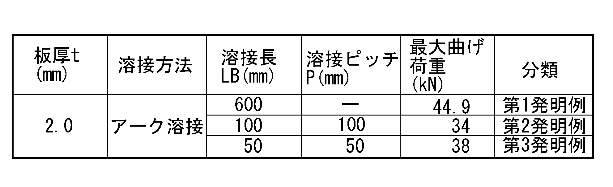
表3に示すように、断続的にアーク溶接する第2発明例及び第3発明例は、全長にアーク溶接する第1発明例に比べて最大曲げ荷重が小さかった。一方、第3発明例は、第2発明例に比べて溶接長LB及び溶接ピッチPが短いものの、最大曲げ荷重が大きかった。したがって、荷重伝達部20を含む接合部21を溶接で断続的に形成する場合には、溶接長LB及び溶接ピッチPを短くすることで、熱ひずみの影響を低減でき、最大曲げ荷重の低下を抑制することができる。
図8Bは、溶接の回数に応じて溶接長を変更した自動車用構造部材42の一例を示す斜視図である。図8Bに示す自動車用構造部材42では、1回目で溶接長を第1の構成部材12の全長であるLAとして、2回目で溶接長をLB、溶接ピッチをPとしている。
表4に最大曲げ試験の試験結果を示す。

表4に示すように、2回目を断続的にアーク溶接する第5発明例は、全ての回で全長にアーク溶接する第4発明例よりも最大曲げ荷重が5%だけ小さかった。したがって、複数回溶接する場合に、2回目以降を断続的に溶接することで、溶け落ちを熱ひずみの影響を低減でき、最大曲げ荷重の低下を抑制することができる。
例えば、1回目で荷重伝達部幅WTが0<WT<0.3t(好ましくは0<WT<0.6t)になるように、あるいはWT<0.3t(好ましくはWT<0.63t)かつ接合幅Lが0<Lになるように全長に亘って溶接し、2回目(あるいは2回目以降)で0.3t≦WT≦1.0t(好ましくは0.6t≦WT≦1.0t)になるように全長よりも短い溶接長で溶接することで、最大曲げ荷重の低下を抑制した上で、溶加材の量を削減することができる。
Claims (11)
- 少なくとも、金属板の成形体からなる第1の構成部材、及び金属板又は金属板の成形体からなるとともに前記第1の構成部材と接合される第2の構成部材により構成される閉じた横断面形状を有する自動車用構造部材であって、
前記第1の構成部材は、縦壁部、該縦壁部につながるとともに前記閉じた横断面形状の内側へ向けて屈曲する曲部、及び該曲部につながる内向きフランジを有するとともに、
前記曲部と前記第2の構成部材との間であって前記縦壁部を前記第2の構成部材へ向けて延長した領域の少なくとも一部の領域に形成されて、前記曲部及び前記第2の構成部材を接合する荷重伝達部を有すること
を特徴とする自動車用構造部材。 - 前記縦壁部の板厚方向への前記荷重伝達部の幅をWTとするとともに、前記縦壁部の板厚をtとした場合に
0.3t≦WT≦1.0t
であることを特徴とする請求項1に記載の自動車用構造部材。 - 前記荷重伝達部は、前記曲部と前記第2の構成部材との間に形成される隙間の一部又は全てを埋める接合部の一部であって、
前記接合部は、前記第2の構成部材と接する範囲である接合幅が、前記荷重伝達部の幅よりも長いことを特徴とする請求項1又は2に記載の自動車用構造部材。 - 前記曲部のうち、少なくとも前記荷重伝達部が接する範囲の硬さが前記第1の構成部材の母材の硬さよりも硬いことを特徴とする請求項1乃至3の何れか1項に記載の自動車用構造部材。
- 前記荷重伝達部は、該自動車用構造部材の長手方向に亘って断続的に形成されることを特徴とする請求項1乃至4の何れか1項に記載の自動車用構造部材。
- 少なくとも、金属板の成形体からなる第1の構成部材、及び金属板又は金属板の成形体からなるとともに前記第1の構成部材と接合される第2の構成部材により構成される閉じた横断面形状を有し、
前記第1の構成部材は、縦壁部、該縦壁部につながるとともに前記閉じた横断面形状の内側へ向けて屈曲する曲部、及び該曲部につながる内向きフランジを有する自動車用構造部材の製造方法であって、
前記曲部と前記第2の構成部材との間であって前記縦壁部を前記第2の構成部材へ向けて延長した領域の少なくとも一部の領域に、溶加材を用いた溶接により、前記曲部及び前記第2の構成部材を接合する荷重伝達部を形成することを特徴とする自動車用構造部材の製造方法。 - 前記荷重伝達部を、前記溶加材を用いた複数回の溶接により形成することを特徴とする請求項6に記載の自動車用構造部材の製造方法。
- 複数回の溶接のうち少なくとも2回の溶接ではそれぞれ溶接長が異なることを特徴とする請求項7に記載の自動車用構造部材の製造方法。
- 前記荷重伝達部は、前記曲部と前記第2の構成部材との間に形成される隙間の一部又は全てを埋める接合部の一部であって、
前記荷重伝達部を、前記溶加材を用いた複数回の溶接によって形成し、
1回目の溶接では、前記荷重伝達部の幅WTがWT<0.6t、かつ前記接合部が前記第2の構成部材と接する範囲である接合幅Lが0<Lになるように溶接し、
2回目以降の溶接において、前記荷重伝達部の幅WTが0.6t≦WT≦1.0tになるように溶接することを特徴とする請求項6乃至8の何れか1項に記載の自動車用構造部材の製造方法。 - 前記荷重伝達部を、該自動車用構造部材の長手方向に亘って断続的に形成することを特徴とする請求項6乃至9の何れか1項に記載の自動車用構造部材の製造方法。
- 前記荷重伝達部を、アーク溶接又はレーザ・アークハイブリッド溶接により前記溶加材を用いて形成することを特徴とする請求項6乃至10の何れか1項に記載の自動車用構造部材の製造方法。
Priority Applications (9)
| Application Number | Priority Date | Filing Date | Title |
|---|---|---|---|
| EP14780360.5A EP2982578B1 (en) | 2013-04-04 | 2014-04-04 | Structural member for automobile, and method for manufacturing same |
| CN201480017817.8A CN105050890B (zh) | 2013-04-04 | 2014-04-04 | 汽车用构造部件及其制造方法 |
| KR1020157025977A KR101780882B1 (ko) | 2013-04-04 | 2014-04-04 | 자동차용 구조 부재 및 그 제조 방법 |
| BR112015024292A BR112015024292A2 (pt) | 2013-04-04 | 2014-04-04 | membro estrutural de automóvel e método de fabricação do mesmo |
| MX2015013107A MX358893B (es) | 2013-04-04 | 2014-04-04 | Miembro estructural para automovil y metodo de fabricacion del mismo. |
| US14/772,537 US9902429B2 (en) | 2013-04-04 | 2014-04-04 | Automobile structural member and manufacturing method of the same |
| RU2015147407A RU2615648C1 (ru) | 2013-04-04 | 2014-04-04 | Автомобильный конструктивный элемент и способ его изготовления |
| JP2015510164A JP6119844B2 (ja) | 2013-04-04 | 2014-04-04 | 自動車用構造部材、及びその製造方法 |
| CA2907413A CA2907413C (en) | 2013-04-04 | 2014-04-04 | Automobile structural member and manufacturing method of the same |
Applications Claiming Priority (2)
| Application Number | Priority Date | Filing Date | Title |
|---|---|---|---|
| JP2013-078835 | 2013-04-04 | ||
| JP2013078835 | 2013-04-04 |
Publications (1)
| Publication Number | Publication Date |
|---|---|
| WO2014163203A1 true WO2014163203A1 (ja) | 2014-10-09 |
Family
ID=51658489
Family Applications (1)
| Application Number | Title | Priority Date | Filing Date |
|---|---|---|---|
| PCT/JP2014/060025 Ceased WO2014163203A1 (ja) | 2013-04-04 | 2014-04-04 | 自動車用構造部材、及びその製造方法 |
Country Status (11)
| Country | Link |
|---|---|
| US (1) | US9902429B2 (ja) |
| EP (1) | EP2982578B1 (ja) |
| JP (1) | JP6119844B2 (ja) |
| KR (1) | KR101780882B1 (ja) |
| CN (1) | CN105050890B (ja) |
| BR (1) | BR112015024292A2 (ja) |
| CA (1) | CA2907413C (ja) |
| MX (1) | MX358893B (ja) |
| RU (1) | RU2615648C1 (ja) |
| TW (1) | TWI592238B (ja) |
| WO (1) | WO2014163203A1 (ja) |
Cited By (4)
| Publication number | Priority date | Publication date | Assignee | Title |
|---|---|---|---|---|
| WO2016174570A1 (en) * | 2015-04-30 | 2016-11-03 | Pietro Passone | Frame of a bus or an industrial transport vehicle |
| JP2017030647A (ja) * | 2015-08-05 | 2017-02-09 | Jfeスチール株式会社 | 自動車用骨格部品および自動車用骨格部品の製造方法 |
| WO2018167896A1 (ja) * | 2017-03-15 | 2018-09-20 | 新日鐵住金株式会社 | 成形体、構造部材、および成形体の製造方法 |
| WO2019230947A1 (ja) * | 2018-05-31 | 2019-12-05 | 株式会社Uacj | 衝撃吸収部材 |
Families Citing this family (13)
| Publication number | Priority date | Publication date | Assignee | Title |
|---|---|---|---|---|
| DE102013213995B4 (de) * | 2013-07-17 | 2015-03-26 | Johnson Controls Components Gmbh & Co. Kg | Rückenlehne für einen Fahrzeugsitz und Fahrzeugsitz |
| KR101923291B1 (ko) * | 2014-05-27 | 2018-11-28 | 신닛테츠스미킨 카부시키카이샤 | 자동차 차체에 있어서의 부재의 접합 구조 |
| US10464511B2 (en) * | 2015-07-08 | 2019-11-05 | Nippon Steel Corporation | Bumper reinforcement and vehicle including the same |
| US10099726B2 (en) * | 2016-11-22 | 2018-10-16 | Ford Global Technologies, Llc | Patch welded blank on an A-pillar |
| CA3059156A1 (en) | 2017-04-10 | 2018-10-18 | Nippon Steel Corporation | Structural member for automobiles |
| JP6819479B2 (ja) * | 2017-06-21 | 2021-01-27 | トヨタ自動車株式会社 | 金属部材及びその製造方法 |
| ES2864103T3 (es) * | 2017-10-11 | 2021-10-13 | Integralia Movilidad S L | Pilar y estructura para un vehículo y vehículo que comprende dicha estructura |
| WO2019122978A1 (en) * | 2017-12-21 | 2019-06-27 | Arcelormittal | Welded steel part used as motor vehicle part, hot pressed steel part, and method of manufacturing said welded steel part |
| KR102535140B1 (ko) * | 2018-11-14 | 2023-05-26 | 닛폰세이테츠 가부시키가이샤 | 골격 부재 |
| US12358559B2 (en) * | 2020-02-18 | 2025-07-15 | Nippon Steel Corporation | Vehicle body structural member and method for designing vehicle body structural member |
| KR102872957B1 (ko) * | 2020-03-31 | 2025-10-17 | 현대자동차주식회사 | T형 용접 이음매의 접합 구조 |
| US11338861B2 (en) | 2020-09-08 | 2022-05-24 | Nissan North America, Inc. | Vehicle roof structure |
| US11318996B2 (en) | 2020-09-09 | 2022-05-03 | Nissan North America, Inc. | Vehicle roof structure |
Citations (7)
| Publication number | Priority date | Publication date | Assignee | Title |
|---|---|---|---|---|
| JPS5667110U (ja) * | 1979-10-29 | 1981-06-04 | ||
| JPH11152541A (ja) | 1997-11-18 | 1999-06-08 | Kobe Steel Ltd | 耐衝撃圧壊特性に優れた高強度鋼板部材 |
| JP2003054445A (ja) | 2001-08-08 | 2003-02-26 | Nippon Steel Corp | 中空構造部材 |
| JP2006205275A (ja) * | 2005-01-25 | 2006-08-10 | Suzuki Motor Corp | 組立体の製造方法および組立補助装置 |
| JP2006224130A (ja) * | 2005-02-16 | 2006-08-31 | Nippon Steel Corp | レーザとマグアークによる複合溶接方法 |
| JP2011168082A (ja) | 2010-02-16 | 2011-09-01 | Sumitomo Metal Ind Ltd | 自動車用構造部材およびその製造方法 |
| JP2012131451A (ja) * | 2010-12-24 | 2012-07-12 | Toyota Boshoku Corp | シートフレーム構造 |
Family Cites Families (19)
| Publication number | Priority date | Publication date | Assignee | Title |
|---|---|---|---|---|
| JPS5667110A (en) | 1979-11-07 | 1981-06-06 | Showa Electric Wire & Cable Co | Crosslinked polyethylene insulated cable |
| SU1379177A1 (ru) | 1986-09-30 | 1988-03-07 | Московский автомеханический институт | Угловое соединение каркаса кабины |
| JP2000033477A (ja) | 1998-07-17 | 2000-02-02 | Hitachi Ltd | 多層盛溶接装置 |
| US6217089B1 (en) | 1999-12-01 | 2001-04-17 | Om Corporation | Bumper reinforcing member |
| US20030184075A1 (en) | 2002-03-27 | 2003-10-02 | Freeman Richard B. | Frame member having overlapping reinforcement sections |
| EP1752250B1 (en) * | 2004-05-18 | 2012-05-23 | Kawasaki Jukogyo Kabushiki Kaisha | Laser welding method, laser welded joint, outer panel, and structure for rolling stock |
| JP2006122983A (ja) | 2004-10-29 | 2006-05-18 | Nissan Motor Co Ltd | 液圧成形用予備成形体、液圧成形方法および液圧成形品 |
| JP4605596B2 (ja) | 2005-03-31 | 2011-01-05 | 富士重工業株式会社 | 車体の板金接合構造 |
| JP4562677B2 (ja) | 2006-03-30 | 2010-10-13 | 株式会社神戸製鋼所 | 溶接構造閉断面フレーム |
| EP2183494B1 (de) * | 2007-08-25 | 2016-01-13 | Accuride International GmbH | Linearführungssystem mit hohlprofilschiene |
| JP4968201B2 (ja) * | 2008-07-04 | 2012-07-04 | 住友金属工業株式会社 | レーザ溶接構造部材およびその製造方法 |
| US7758107B2 (en) * | 2008-07-29 | 2010-07-20 | Ford Global Technologies, Llc | Dual cell body side rail for automotive vehicles |
| JP5074456B2 (ja) | 2009-06-03 | 2012-11-14 | 本田技研工業株式会社 | 車両用強度部材 |
| DE102010016474A1 (de) | 2010-04-16 | 2011-10-20 | Thyssenkrupp Steel Europe Ag | Trägerelement für ein Kraftfahrzeug |
| JP5613444B2 (ja) | 2010-04-26 | 2014-10-22 | 本田技研工業株式会社 | 自動二輪車の車体フレーム |
| CN102151954A (zh) * | 2011-02-23 | 2011-08-17 | 格菱动力设备(中国)有限公司 | 集箱管座角焊缝焊接的操作方法 |
| WO2012120967A1 (ja) * | 2011-03-10 | 2012-09-13 | 本田技研工業株式会社 | 自動車の車体フレーム構造 |
| CN202463922U (zh) | 2012-01-12 | 2012-10-03 | 张家港市隆旌汽车零部件有限公司 | 汽车纵梁 |
| CN102909479B (zh) | 2012-09-29 | 2015-07-29 | 郑州市嵩阳煤机制造有限公司 | 方形长钢梁焊接方法 |
-
2014
- 2014-04-04 CA CA2907413A patent/CA2907413C/en not_active Expired - Fee Related
- 2014-04-04 MX MX2015013107A patent/MX358893B/es active IP Right Grant
- 2014-04-04 KR KR1020157025977A patent/KR101780882B1/ko active Active
- 2014-04-04 CN CN201480017817.8A patent/CN105050890B/zh active Active
- 2014-04-04 EP EP14780360.5A patent/EP2982578B1/en active Active
- 2014-04-04 US US14/772,537 patent/US9902429B2/en active Active
- 2014-04-04 WO PCT/JP2014/060025 patent/WO2014163203A1/ja not_active Ceased
- 2014-04-04 BR BR112015024292A patent/BR112015024292A2/pt not_active IP Right Cessation
- 2014-04-04 JP JP2015510164A patent/JP6119844B2/ja active Active
- 2014-04-04 RU RU2015147407A patent/RU2615648C1/ru not_active IP Right Cessation
- 2014-04-07 TW TW103112686A patent/TWI592238B/zh not_active IP Right Cessation
Patent Citations (7)
| Publication number | Priority date | Publication date | Assignee | Title |
|---|---|---|---|---|
| JPS5667110U (ja) * | 1979-10-29 | 1981-06-04 | ||
| JPH11152541A (ja) | 1997-11-18 | 1999-06-08 | Kobe Steel Ltd | 耐衝撃圧壊特性に優れた高強度鋼板部材 |
| JP2003054445A (ja) | 2001-08-08 | 2003-02-26 | Nippon Steel Corp | 中空構造部材 |
| JP2006205275A (ja) * | 2005-01-25 | 2006-08-10 | Suzuki Motor Corp | 組立体の製造方法および組立補助装置 |
| JP2006224130A (ja) * | 2005-02-16 | 2006-08-31 | Nippon Steel Corp | レーザとマグアークによる複合溶接方法 |
| JP2011168082A (ja) | 2010-02-16 | 2011-09-01 | Sumitomo Metal Ind Ltd | 自動車用構造部材およびその製造方法 |
| JP2012131451A (ja) * | 2010-12-24 | 2012-07-12 | Toyota Boshoku Corp | シートフレーム構造 |
Cited By (9)
| Publication number | Priority date | Publication date | Assignee | Title |
|---|---|---|---|---|
| WO2016174570A1 (en) * | 2015-04-30 | 2016-11-03 | Pietro Passone | Frame of a bus or an industrial transport vehicle |
| US10501127B2 (en) | 2015-04-30 | 2019-12-10 | Baomarc Automotive Solutions S.p.A. | Frames for buses or industrial transport vehicles |
| JP2017030647A (ja) * | 2015-08-05 | 2017-02-09 | Jfeスチール株式会社 | 自動車用骨格部品および自動車用骨格部品の製造方法 |
| WO2018167896A1 (ja) * | 2017-03-15 | 2018-09-20 | 新日鐵住金株式会社 | 成形体、構造部材、および成形体の製造方法 |
| EP3597512A4 (en) * | 2017-03-15 | 2020-11-11 | Nippon Steel Corporation | MOLDED BODY, STRUCTURAL ELEMENT AND MOLDED BODY MANUFACTURING PROCESS |
| US11623260B2 (en) | 2017-03-15 | 2023-04-11 | Nippon Steel Corporation | Formed body, structural member, and method for producing formed body |
| WO2019230947A1 (ja) * | 2018-05-31 | 2019-12-05 | 株式会社Uacj | 衝撃吸収部材 |
| JP2019209727A (ja) * | 2018-05-31 | 2019-12-12 | 株式会社Uacj | 衝撃吸収部材 |
| US11254271B2 (en) | 2018-05-31 | 2022-02-22 | Uacj Corporation | Shock-absorbing member |
Also Published As
| Publication number | Publication date |
|---|---|
| TWI592238B (zh) | 2017-07-21 |
| CA2907413A1 (en) | 2014-10-09 |
| TW201507795A (zh) | 2015-03-01 |
| CA2907413C (en) | 2017-06-13 |
| MX358893B (es) | 2018-09-07 |
| CA2907413E (en) | 2014-10-09 |
| JPWO2014163203A1 (ja) | 2017-02-16 |
| US20160016610A1 (en) | 2016-01-21 |
| CN105050890A (zh) | 2015-11-11 |
| US9902429B2 (en) | 2018-02-27 |
| KR20150121709A (ko) | 2015-10-29 |
| KR101780882B1 (ko) | 2017-09-21 |
| JP6119844B2 (ja) | 2017-04-26 |
| EP2982578A4 (en) | 2016-12-07 |
| EP2982578B1 (en) | 2021-01-20 |
| EP2982578A1 (en) | 2016-02-10 |
| CN105050890B (zh) | 2017-10-17 |
| MX2015013107A (es) | 2016-01-22 |
| RU2615648C1 (ru) | 2017-04-06 |
| BR112015024292A2 (pt) | 2017-07-18 |
Similar Documents
| Publication | Publication Date | Title |
|---|---|---|
| JP6119844B2 (ja) | 自動車用構造部材、及びその製造方法 | |
| JP7422080B2 (ja) | テーラードブランク、テーラードブランクの製造方法、プレス成形品、及び、プレス成形品の製造方法 | |
| JP6125992B2 (ja) | 自動車構成部材用成形部材 | |
| US8276954B2 (en) | Bumper system | |
| JP5076690B2 (ja) | 車体閉断面構造部材の製造方法 | |
| JP2009001121A (ja) | 車両用センターピラーの補強部材 | |
| CN119840736A (zh) | 用于机动车辆的后底置结构 | |
| CN112703130A (zh) | 具有钢加强件的保险杠梁 | |
| CN108025404A (zh) | 具有改进的接合特性的构件结构的生产方法和构件结构 | |
| JP6284899B2 (ja) | バンパリインフォースメント | |
| US12428064B2 (en) | Rocker reinforcement for an electric vehicle | |
| JP7425306B2 (ja) | 成形品、自動車用構造部材および成形品の製造方法 | |
| US20250091424A1 (en) | Floor frame for a motor vehicle body | |
| JP5158246B2 (ja) | 衝撃吸収部材 | |
| WO2026084035A1 (ja) | 車両用サイドフレーム部品およびその一体化ブランク | |
| CN120530050A (zh) | 用于机动车辆的后部结构 | |
| KR20200126522A (ko) | 차량용 시트 크로스 멤버 조립체 |
Legal Events
| Date | Code | Title | Description |
|---|---|---|---|
| WWE | Wipo information: entry into national phase |
Ref document number: 201480017817.8 Country of ref document: CN |
|
| 121 | Ep: the epo has been informed by wipo that ep was designated in this application |
Ref document number: 14780360 Country of ref document: EP Kind code of ref document: A1 |
|
| ENP | Entry into the national phase |
Ref document number: 2015510164 Country of ref document: JP Kind code of ref document: A |
|
| WWE | Wipo information: entry into national phase |
Ref document number: 14772537 Country of ref document: US |
|
| WWE | Wipo information: entry into national phase |
Ref document number: MX/A/2015/013107 Country of ref document: MX |
|
| ENP | Entry into the national phase |
Ref document number: 2907413 Country of ref document: CA |
|
| WWE | Wipo information: entry into national phase |
Ref document number: 2014780360 Country of ref document: EP |
|
| ENP | Entry into the national phase |
Ref document number: 20157025977 Country of ref document: KR Kind code of ref document: A |
|
| WWE | Wipo information: entry into national phase |
Ref document number: IDP00201506185 Country of ref document: ID |
|
| NENP | Non-entry into the national phase |
Ref country code: DE |
|
| ENP | Entry into the national phase |
Ref document number: 2015147407 Country of ref document: RU Kind code of ref document: A |
|
| REG | Reference to national code |
Ref country code: BR Ref legal event code: B01A Ref document number: 112015024292 Country of ref document: BR |
|
| ENP | Entry into the national phase |
Ref document number: 112015024292 Country of ref document: BR Kind code of ref document: A2 Effective date: 20150922 |