WO2014167861A1 - 送信方法 - Google Patents
送信方法 Download PDFInfo
- Publication number
- WO2014167861A1 WO2014167861A1 PCT/JP2014/002064 JP2014002064W WO2014167861A1 WO 2014167861 A1 WO2014167861 A1 WO 2014167861A1 JP 2014002064 W JP2014002064 W JP 2014002064W WO 2014167861 A1 WO2014167861 A1 WO 2014167861A1
- Authority
- WO
- WIPO (PCT)
- Prior art keywords
- 16apsk
- symbol
- signal point
- signal
- cos
- Prior art date
- Legal status (The legal status is an assumption and is not a legal conclusion. Google has not performed a legal analysis and makes no representation as to the accuracy of the status listed.)
- Ceased
Links
Images


Classifications
-
- H—ELECTRICITY
- H04—ELECTRIC COMMUNICATION TECHNIQUE
- H04L—TRANSMISSION OF DIGITAL INFORMATION, e.g. TELEGRAPHIC COMMUNICATION
- H04L27/00—Modulated-carrier systems
- H04L27/0008—Modulated-carrier systems arrangements for allowing a transmitter or receiver to use more than one type of modulation
-
- H—ELECTRICITY
- H04—ELECTRIC COMMUNICATION TECHNIQUE
- H04L—TRANSMISSION OF DIGITAL INFORMATION, e.g. TELEGRAPHIC COMMUNICATION
- H04L27/00—Modulated-carrier systems
- H04L27/32—Carrier systems characterised by combinations of two or more of the types covered by groups H04L27/02, H04L27/10, H04L27/18 or H04L27/26
- H04L27/34—Amplitude- and phase-modulated carrier systems, e.g. quadrature-amplitude modulated carrier systems
-
- H—ELECTRICITY
- H04—ELECTRIC COMMUNICATION TECHNIQUE
- H04W—WIRELESS COMMUNICATION NETWORKS
- H04W28/00—Network traffic management; Network resource management
- H04W28/02—Traffic management, e.g. flow control or congestion control
- H04W28/0252—Traffic management, e.g. flow control or congestion control per individual bearer or channel
- H04W28/0263—Traffic management, e.g. flow control or congestion control per individual bearer or channel involving mapping traffic to individual bearers or channels, e.g. traffic flow template [TFT]
Definitions
- Japanese Patent Application No. 2013-084269, Japanese Patent Application No. 2013-084270, and Japanese Patent Application No. 2013-084271 filed on April 12, 2013, and May 9, 2013 Disclosure contents of claims, description, drawings and abstract contained in Japanese Patent Application No. 2013-099605, Japanese Patent Application No. 2013-099606 and Japanese Patent Application No. 2013-099607 Are all incorporated herein by reference.
- the present invention relates to a signal transmission method for performing iterative detection on the receiving side.
- Non-Patent Document 1 improves the reception quality of data for BICM-ID (Bit Interleaved Coded Modulation-Iterative Detection) by changing the bit labeling mode for QAM (Quadrature Amplitude Modulation). Consideration is being made.
- BICM-ID Bit Interleaved Coded Modulation-Iterative Detection
- QAM Quadrature Amplitude Modulation
- Non-Patent Document 1 relating to QAM labeling to a communication / broadcasting system.
- An object of the present invention is to provide a transmission method that contributes to improvement in data reception quality when iterative detection is performed on the reception side in a communication / broadcast system, for example.
- a transmission method is a transmission device that transmits data by a modulation method that shifts amplitude and phase, and the first modulation method and the first modulation method that are different in signal point arrangement and bit allocation to each signal point.
- a selection unit that alternately selects two modulation schemes for each symbol, a mapping unit that maps to a signal point corresponding to the selected modulation scheme, and a transmission unit that transmits the mapped modulation signal,
- the first modulation scheme four signal points are arranged on the circumference of the inner circle on the IQ plane, and twelve signal points are arranged on the circumference of the outer circle.
- the bit allocation of the pair is 1 bit, and the set of signal points on the circumference of the outer circle and the set of signal points on the circumference of the inner circle, which are the shortest on the IQ plane, between different groups
- 8 signal points are arranged on the circumference of the inner circle and 8 points on the circumference of the outer circle in the IQ plane.
- a first group of 16 APSK modulations in which the inner circle and the outer circle are concentric with each other, and the 16 signal points are composed of 8 signal points on the circumference of the inner circle.
- Divide into a second group consisting of 8 signal points on the circumference of the outer circle In the case, the set of signal points that are adjacent on the circumference, of the assignment of bit differences is one bit in the same group.
- an error correction code having a high error correction capability such as an LDPC (Low Density Parity Check) code or a turbo code such as a Duo-binary Turbo code is applied to a communication / broadcasting system.
- LDPC Low Density Parity Check
- turbo code such as a Duo-binary Turbo code
- Example of input / output characteristics of a power amplifier installed in a transmitter Configuration example of communication system using BICM-ID method An example of input and output of the encoder of the transmitter An example of bit-reduction encoder of transmitter An example of bit-reduction decoder of receiver Example of input / output of XOR part of bit-reduction decoder Configuration diagram of transmitter (12,4) 16APSK signal point map (8,8) 16APSK signal point map Block diagram for modulation signal generation Modulated signal frame structure Data symbol example Pilot symbol example (12,4) 16APSK labeling example (12,4) 16APSK labeling example (8,8) 16APSK labeling example Example of (8,8) 16APSK signal point arrangement Image of transmission signal frame structure in advanced broadband satellite digital broadcasting Configuration diagram of receiver Examples of modulation schemes Examples of modulation schemes Configuration example of stream type / relative stream information Examples of modulation schemes Example of symbol placement Example of 32APSK signal point arrangement Example of NU-16QAM signal point arrangement and labeling Image of broadband satellite digital broadcasting Block diagram for ring ratio determination Diagram for explaining the band limiting
- PAPR Peak-to-Average power ratio
- Peak-to-Average power ratio Pulse-to-Average power ratio
- FIG. 1 shows the input / output characteristics of the power amplifier mounted on the transmission apparatus.
- the PAPR when using the modulation method #A is 7.0 dB and the PAPR when using the modulation method #B is 8.0 dB.
- this embodiment aims to provide a modulation scheme and transmission method with small PAPR and good data reception quality.
- Non-Patent Document 1 examination of improvement of data reception quality at the time of BICM-ID is performed depending on how bits are labeled for QAM.
- error correction codes having high error correction capability such as LD codes (Low-Density Parity-Check code) codes and turbo codes such as Duo-binary Turbo codes
- LD codes Low-Density Parity-Check code
- turbo codes such as Duo-binary Turbo codes
- this embodiment applies an error correction code having a high error correction capability such as an LDPC code or a turbo code, and obtains high data reception quality when iterative detection (or detection) is performed on the reception side.
- an error correction code having a high error correction capability such as an LDPC code or a turbo code
- FIG. 2 is a diagram illustrating a configuration example of a communication system using the BICM-ID scheme.
- bit-reduction encoder 203 and bit-reduction decoder 215 will be described, but even in the case of not having bit-reduction encoder 203 and bit-reduction2decoder 215, iterative detection (Iterative Detection) can be performed.
- the transmission apparatus 200 includes an encoding unit 201, an interleaver 202, a bit-reduction encoder 203, a mapping unit 204, a modulation unit 205, a transmission RF (Radio Frequency) unit 206, and a transmission antenna 207.
- an encoding unit 201 an interleaver 202, a bit-reduction encoder 203, a mapping unit 204, a modulation unit 205, a transmission RF (Radio Frequency) unit 206, and a transmission antenna 207.
- a transmission RF Radio Frequency
- the reception device 210 includes a reception antenna 211, a reception RF unit 212, a demodulation unit 213, a demapping unit 214, a bit-reduction decoder 215, a deinterleaver 216, a decoding unit 217, and an interleaver 218.
- FIG. 3 shows an example of input / output of the encoding unit 201 of the transmission apparatus 200.
- the encoding unit 201 performs encoding at an encoding rate R1, and when an information bit having a bit number N info is input, outputs an encoded bit having a bit number N info / R1.
- FIG. 4 shows an example of the bit-reduction encoder 203 of the transmission device 200.
- an 8-bit bit string b (b 0 to b 7 ) is input from the bit-reduction encoder 203 and the interleaver 202 in this example, a conversion with a reduction in the number of bits is performed, and a 4-bit bit string m (m 0 to m m 3 ) is output to the mapping unit 204.
- [+] indicates an XOR (exclusive-or) part.
- the bit-reduction encoder 203 of this example includes a system in which an input unit of bit b 0 and an output unit of bit m 0 are connected by an XOR unit, an input unit of bits b 1 and b 2 , and an output unit of bit m 1.
- a system connected by the XOR section a system in which the input sections of the bits b 3 and b 4 and the output section of the bit m2 are connected by the XOR section, an input section of the bits b 5 , b 6 and b 7 and an output of the bit m 3
- a system in which the parts are connected by an XOR part.
- FIG. 5 shows an example of the bit-reduction decoder 215 of the receiving device 210.
- the bit-reduction decoder 215 of the present example includes L (m 0 ) to L (m 3 ) that are LLRs (Log Likelihood Ratio) of the 4-bit bit string m (m 0 to m 3 ) from the demapping unit 214. )
- L (b 0 ) to L (b 7 ) which are LLRs of the 8-bit bit string b (b 0 to b 7 ).
- L (b 0 ) to L (b 7 ) that are LLRs of the bit string b (b 0 to b 7 ) are input to the decoding unit 217 via the deinterleaver 216.
- bit-reduction decoder 215 receives L (b 0 ) to L (b 7 ), which are LLRs of the 8-bit bit string b (b 0 to b 7 ) passed through the interleaver 218 from the decoding unit 217, Conversion with reduction in the number of bits is performed, and L (m 0 ) to L (m 3 ), which are LLRs of the 4-bit bit string m (m 0 to m 3 ), are output to the demapping unit 214.
- the bit-reduction decoder 215 of this example includes a system in which an input / output unit of L (b 0 ) and an input / output unit of L (m 0 ) are connected by an XOR unit, and L (b 1 ), L (b 2 ) Input / output unit and L (m 1 ) input / output unit connected by an XOR unit, L (b 3 ), L (b 4 ) input / output unit and L (m 2 ) input / output unit And a system in which an input / output unit of L (b 5 ), L (b 6 ), L (b 7 ) and an input / output unit of L (m 3 ) are connected by an XOR unit. Have.
- bit b 0 is LSB (Least Significant Bit)
- bit b 7 is MSB (Most Significant Bit). Bit, most significant bit).
- bit m is LSB
- bit m 3 is MSB.
- FIG. 6 shows the input / output of the XOR (exclusive-or) unit for explaining the operation of the bit-reduction decoder 215.
- bits u 1 and u 2 and bit u 3 are connected by an XOR section.
- L (u 1 ), L (u 2 ), and L (u 3 ), which are LLRs of the bits u 1 , u 2 , and u 3 are also shown. The relationship among L (u 1 ), L (u 2 ), and L (u 3 ) will be described later.
- the transmission bit encoding section 201 receives the transmission bit as input and performs (error correction) encoding.
- the coding rate of the error correction code used in the coding unit 201 is R1
- the code The number of output bits from the conversion unit 201 is N info / R1.
- the signal (data) encoded by the encoding unit 201 is subjected to interleave processing (data rearrangement) by the interleaver 202 and then input to the bit-reduction encoder 203. Then, as described with reference to FIG. 3, the bit number reduction process is performed by the bit-reduction encoder 203. Note that the bit number reduction process may not be performed.
- the mapping unit 204 performs mapping processing on the signal (data) that has been subjected to the bit number reduction processing.
- the modulation unit 205 performs processing such as conversion of the mapped signal from a digital signal to an analog signal, band limitation, orthogonal modulation, and multi-carrier conversion (such as OFDM (Orthogonal Frequency Division Multiplexing)). I do.
- the signal subjected to this signal processing is transmitted by radio from, for example, the transmission antenna 207 via a transmission RF (Radio Frequency) processing (206) for performing transmission processing.
- RF Radio Frequency
- the reception RF (212) performs processing such as frequency conversion and orthogonal demodulation on the signal received by the reception antenna 211 (radio signal from the transmission side) to generate a baseband signal and demodulate it. Output to the unit 213.
- Demodulation section 213 performs processing such as channel estimation and demodulation, generates a demodulated signal, and outputs it to mapping section 214.
- the demapping unit 214 calculates an LLR (log likelihood ratio) for each bit based on the reception signal input from the demodulation unit 213, the noise power included in the reception signal, and the prior information obtained from the bit-reduction decoder 215. calculate.
- LLR log likelihood ratio
- the demapping unit 214 performs processing on the signal mapped by the mapping unit 204. That is, the demapping unit 214 calculates the LLR for the bit string (corresponding to the bit string m in FIGS. 4 and 5) after the bit number reduction process is performed on the transmission side.
- the LLR mapping after bit reduction
- the bit-reduction decoder 215 converts the LLR after the bit number reduction input from the demapping unit 214 into an LLR at a point before the bit number reduction (corresponding to the bit string b in FIGS. 4 and 5). Details of the processing will be described later.
- the LLR calculated by the bit-reduction decoder 215 is input to the decoding unit 217 after being deinterleaved by the deinterleaver 216.
- the decoding unit 217 performs a decoding process based on the input LLR, thereby calculating the LLR again.
- the LLR calculated by the decoding unit 217 is interleaved by the interleaver 218 and then fed back to the bit-reduction / decoder 215.
- the bit-reduction / decoder 215 converts the LLR fed back from the decoding unit 217 into an LLR after the number of bits is reduced, and inputs the LLR to the demapping unit 214.
- the demapping unit 214 again calculates the LLR for each bit based on the received signal, the noise power included in the received signal, and the prior information obtained from the bit-reduction decoder 215.
- bit number reduction process is not performed on the transmission side, no special process in the bit-reduction decoder 215 is performed.
- a bit string b (b 0 , b 1 ,..., B N-1 ) of N bits (N is an integer of 1 or 2 or more) is converted into M (M is an integer of 1 or 2 or more) symbol points Sk ( Consider the LLR output from the demapping unit 214 when assigned to S 0 , S 1 ,..., S M ⁇ 1 ).
- Equation (1) holds.
- the first term on the last right side of the equation (1) is an LLR obtained from other than the i-th bit, and this is set as external information Le (b i ).
- the second term on the last right side of Equation (1) is an LLR obtained based on the prior probability of the i-th bit, and this is referred to as prior information L a (b i ). Then, Expression (1) becomes Expression (2) and can be transformed into Expression (3).
- the demapping unit 214 outputs the processing result of Expression (3) as an LLR.
- Equation (5) holds for the denominator p (y
- b i 1) of the first term on the last right side of Equation (1). Therefore, the first term on the last right side of the equation (1) is the equation (6).
- Equation (8) becomes It holds.
- Equation (9) Equation (10) is obtained.
- the demapping unit 214 when performing the iterative processing in BICM-ID, performs an exponential operation and a sum operation for each symbol point and each bit allocated to the point, and uses them as a denominator / numerator. Each of them is obtained and then it is logarithmically calculated.
- the bit-reduction decoder 215 converts the LLR after the bit number reduction calculated by the demapping unit 214 into the LLR before the bit number reduction required by the decoding unit 217, and the bit before the bit number reduction calculated by the decoding unit 217.
- the LLR is converted into an LLR after the number of bits required by the demapping unit 214 is reduced.
- bit-reduction decoder 2115 the process of converting the LLR before and after the bit reduction is performed for each [+] (for each XOR section) in FIG. 5, and an operation is performed using the bits connected to the [+].
- each bit is set to u 1 , u 2 , u 3
- the LLR of each bit is set to L (u 1 ), L (u 2 ), L (u 3 ), L Consider L (u 3 ) when (u 1 ) and L (u 2 ) are given.
- u 1 expected value E [u 1] is a formula (18).
- Equation (21) is obtained.
- L (b 7 ) is expressed as L (b 7 ). If seeking, L (m 3), L (b 6), with L (b 5), the equation (22).
- bit number reduction processing is not performed on the transmission side, the above-described special processing is not performed.
- FIG. 7 is a configuration diagram of the transmission apparatus.
- the transmission apparatus 700 includes an error correction encoding unit 702, a control information generation unit 704, an interleaving unit 706, a mapping unit 708, a modulation unit 710, and a radio unit 712.
- the error correction coding unit 702 receives the control signal and the information bits, and determines, for example, the code length (block length) of the error correction code and the coding rate of the error correction code based on the control signal. Thus, error correction coding is performed based on the determined error correction coding method, and the bits after error correction coding are output to the interleave unit 706.
- Interleave section 706 receives the control signal and the encoded bits, determines an interleaving method based on the control signal, interleaves (rearranges) the encoded bits, and maps the rearranged data to mapping section 708. To output.
- the control information generation and mapping unit 704 receives a control signal, and based on the control signal, control information for operating the receiving device (for example, information on the physical layer such as an error correction method and a modulation method used by the transmitting device, , Control information other than the physical layer, etc.) is generated, mapped to this information, and a control information signal is output.
- control information for operating the receiving device for example, information on the physical layer such as an error correction method and a modulation method used by the transmitting device, , Control information other than the physical layer, etc.
- the mapping unit 708 receives the control signal and the rearranged data as input, determines a mapping method based on the control signal, performs mapping on the rearranged data by the determined mapping method, and baseband signal in-phase component I and quadrature component Q are output.
- Examples of modulation schemes that can be supported by the mapping unit 708 include ⁇ / 2 shift BPSK, QPSK, 8PSK, (12,4) 16APSK, (8,8) 16APSK, and 32APSK.
- Modulation section 710 receives a control signal, control information signal, pilot signal, and baseband signal as input, determines a frame configuration based on the control signal, and modulates according to the frame configuration from the control information signal, pilot signal, and baseband signal. Generate and output a signal.
- the radio unit 712 receives the modulated signal, performs processing such as band limitation, quadrature modulation, frequency conversion, and amplification using a root roll-off filter, generates a transmission signal, and the transmission signal is transmitted from the antenna.
- processing such as band limitation, quadrature modulation, frequency conversion, and amplification using a root roll-off filter
- the signal points of (12,4) 16APSK mapping are arranged in two concentric circles having different radii (amplitude components) in the IQ plane.
- a circle having a larger radius R 2 is called an “outer circle”
- a circle having a smaller radius R 1 is called an “inner circle”.
- the ratio between the radius R 2 and the radius R 1 is called “radius ratio” (or “ring ratio”).
- R 1 is a real number
- R 2 is a real number
- R 1 ⁇ R 2 is satisfied.
- 12 signal points are arranged on the circumference of the outer circle, and 4 signal points are arranged on the circumference of the inner circle.
- (12,4) of (12,4) 16APSK means that there are 12 and 4 signal points in the order of the outer circle and the inner circle, respectively.
- the unit is radians.
- the unit of ⁇ / 4 is radians.
- the unit of phase is radians.
- Signal point 1-1 [0000] ... (R 2 cos ( ⁇ / 4), R 2 sin ( ⁇ / 4))
- Another example is Signal point 4-4 [0101] ...
- Signal point 1-1, signal point 1-2, signal point 1-3, signal point 1-4, signal point 2-1, signal point 2-2, signal point 2-3, signal point 2-4, signal point 3-1, signal point 3-2, signal point 3-3, signal point 3-4, signal point 4-1, signal point 4-2, signal point 4-3, signal point 4-4 are all the same. .
- the signal points of (8,8) 16APSK mapping are arranged in two concentric circles having different radii (amplitude components) in the IQ plane. Eight signal points are arranged on the circumference of the outer circle, and eight signal points are arranged on the circumference of the inner circle. (8,8) of (8,8) 16APSK means that there are 8 signal points in the order of the outer circle and the inner circle.
- a circle having a larger radius R 2 among concentric circles is called an “outer circle”, and a circle having a smaller radius R 1 is called an “inner circle”.
- the ratio between the radius R 2 and the radius R 1 is called “radius ratio” (or “ring ratio”).
- R 1 is a real number
- R 2 is a real number
- R 1 ⁇ R 2 .
- Signal point 1-1, signal point 1-2, signal point 1-3, signal point 1-4, signal point 1-5, signal point 1-6, signal point 1-7, signal point 1-8, signal point 2-1, signal point 2-2, signal point 2-3, signal point 2-4, signal point 2-5, signal point 2-6, signal point 2-7, signal point 2-8 are all the same. .
- a ( 12,4 ) is a normalization coefficient of (12,4) 16APSK
- a (8,8) is a coefficient of (8,8) 16APSK.
- Signal point 1-1, signal point 1-2, signal point 1-3, signal point 1-4, signal point 2-1, signal point 2-2, signal point 2-3, signal point 2-4, signal point 3-1, signal point 3-2, signal point 3-3, signal point 3-4, signal point 4-1, signal point 4-2, signal point 4-3, signal point 4-4 are all the same. .
- the in-phase component of the baseband signal before normalization is I b
- the quadrature component is Q b is the baseband signal after mapping obtained by mapping based on FIG. In-phase component I and quadrature component Q. Therefore, the following relationship is established when (8,8) 16APSK.
- Signal point 1-1, signal point 1-2, signal point 1-3, signal point 1-4, signal point 1-5, signal point 1-6, signal point 1-7, signal point 1-8, signal point 2-1, signal point 2-2, signal point 2-3, signal point 2-4, signal point 2-5, signal point 2-6, signal point 2-7, signal point 2-8 are all the same.
- FIG. 10 is a block diagram relating to generation of a modulated signal.
- FIG. 11 shows a frame structure of the modulation signal.
- the TMCC (Transmission and Multiplexing Configuration Control) signal is a control signal that controls transmission and multiplexing such as a plurality of transmission modes (modulation scheme and error correction coding rate). Further, the TMCC signal indicates the allocation of modulation schemes for each symbol (or a slot composed of a plurality of symbols).
- the selection unit 1001 in FIG. 10 switches the contact 1 and the contact 2 so that the symbol string of the modulated wave output is arranged as shown in FIG. Specifically, switching is performed as listed below.
- Interleaving section 706 performs bit interleaving (bit rearrangement) based on the information of the control signal.
- the mapping unit 708 performs mapping by the method selected by the selection unit 1001 based on the information of the control signal.
- Modulation section 710 performs processing such as time division multiplexing / orthogonal modulation and band limitation using a route roll-off filter based on the information of the control signal, and outputs a modulated wave.
- (12,4) 16APSK is used as a modulation method for transmitting 4 bits by 16 signal points, that is, 1 symbol, in the in-phase I-orthogonal Q plane.
- (12,4) 16APSK PAPR is smaller than, for example, 16QAM PAPR, (8,8) 16APSK PAPR, and the average transmission power of radio waves transmitted from broadcasting stations, that is, satellites, is increased. This is because there is an advantage that it can be done.
- the modulation method (or transmission method) has 16 signal points and the PAPR is small and the BER characteristics are good, there is a possibility that a wide receivable area can be secured. Is expensive.
- the present invention is based on this point. ("Better BER characteristics" corresponds to a smaller BER at a certain SNR.)
- the essence of the data symbol construction method according to the present invention is as follows. “In a symbol group in which the modulation method is either (12,4) 16APSK or (8,8) 16APSK, 3 symbols or more (or 4 symbols or more) are consecutive, (12,4) 16APSK symbols There is no continuous part, and there is no part where the (8,8) 16APSK symbol is continuous. “(However, as described in this modification below, even in a method that does not satisfy this, There is a transmission method capable of obtaining the same effect as in the above symbol arrangement example.)
- the odd-numbered symbol has a modulation scheme of (12,4) 16APSK and the even-numbered symbol has a modulation scheme of (8,8) 16APSK.
- FIG. 12 shows 6 symbols out of 136 symbols ("51st symbol” to "56th symbol”). As shown in Figure 12, adjacent to (12,4) 16APSK, (8,8) 16APSK, (12,4) 16APSK, (8,8) 16APSK, (12,4) 16APSK, (8,8) 16APSK It can be seen that two types of modulation schemes are used alternately between symbols to be processed.
- the transmission device transmits the component.
- (Modulation method: (12,4) 16APSK) 4 bits [b 3 b 2 b 1 b 0 ] [0110] transmitted in the “54th symbol”, and as shown in FIG. 12, the in-phase component and quadrature of the baseband signal corresponding to the signal point ⁇
- the transmission device transmits the component.
- the transmission device transmits the component.
- the transmission device transmits the component.
- Modulation method: (8,8) 16APSK
- This provides a transmission method with a low PAPR and good BER characteristics, and can set a large average transmission power and good BER characteristics, so there is a high possibility that a wide receivable area can be secured.
- the modulation scheme is In a symbol group in which symbols that are either (12,4) 16APSK or (8,8) 16APSK are continuous for 3 symbols or more (or 4 symbols or more), a portion in which (12,4) 16APSK symbols are continuous It does not exist, and there is no portion where (8,8) 16APSK symbols continue.
- R 1 and R 2 which was used to represent the signal points in I-Q plane of 16APSK
- Ring ratio 16APSK R a (12,4) R (12,4) It shall be expressed as R 2 / R 1 .
- R (8,8) should be set small, while R ( 12,4) in (12,4) 16APSK is set to a value that improves the BER characteristics. If you do, you have a high degree of freedom. For this reason, it is highly possible that there is a relationship of R (8,8) ⁇ R (12,4) .
- R (8,8) > R (12,4) the effect that it can be made smaller than the PAPR of (8,8) 16APSK is obtained. Therefore, when focusing on improving the BER characteristics, R (8,8) > R (12,4) may be good.
- the relationship between the ring ratios is the same in the case of the modification described below ( ⁇ switching pattern of modulation schemes>). According to the embodiment described above, by alternately arranging symbols of different modulation schemes, it is possible to contribute to providing good data reception quality with low PAPR.
- the gist of the present invention is as follows: “In a symbol group in which a symbol whose modulation method is (12,4) 16APSK or (8,8) 16APSK is continuous for 3 symbols or more (or 4 symbols or more). , (12,4) 16APSK symbols do not continue, and (8,8) 16APSK symbols do not exist ”.
- (12,4) 16APSK labeling and signal point arrangement, and (8,8) 16APSK labeling and signal point to increase the possibility that the receiving device can obtain high data reception quality. The arrangement will be described.
- FIG. 8 shows an example of (12,4) 16APSK labeling, but labeling that satisfies the following ⁇ Condition 1> and ⁇ Condition 2> may be used.
- the signal point A is given in the in-phase I-quadrature Q plane
- the 4 bits to be transmitted is [b b3 b b2 b b1 b b0 ]
- the signal point B is given in the in-phase I-orthogonal Q plane.
- the number of bits with different labeling is defined as one.
- the number of bits with different labeling is defined as two.
- the number of bits with different labeling is defined as two.
- the number of bits with different labeling is defined as three.
- the number of bits with different labeling for signal point X-1 and signal point X-2 is 1
- the number of bits with different labeling for signal point X-2 and signal point X-3 is 1
- the number of bits with different labeling for signal point X-3 and signal point X-4 is 1
- the number of bits with different labeling for signal point X-4 and signal point X-1 is 1
- ⁇ Condition 2> For the outer circle, The number of bits with different labeling for signal point 1-2 and signal point 2-2 is 1. The number of bits with different labeling for signal point 3-2 and signal point 4-2 is 1. The number of bits with different labeling for signal points 1-4 and 4-4 is 1 The number of bits with different labeling for signal points 2-4 and 3-4 is 1
- the number of bits with different labeling for signal points 1-3 and 2-3 is 1
- the number of bits with different labeling for signal point 2-3 and signal point 3-3 is 1
- the number of bits with different labeling for signal point 3-3 and signal point 4-3 is 1
- the number of bits with different labeling for signal point 4-3 and signal point 1-3 is 1 Is established.
- the receiving device may be able to obtain high data reception quality. Becomes higher. As a result, when the receiving apparatus performs iterative detection, there is a high possibility that high data reception quality can be obtained.
- the unit is radians. Therefore, the in-phase component of the normalized baseband signal is represented by I n and the quadrature component is represented by Q n as follows.
- ⁇ is a phase given on the in-phase I-orthogonal Q plane
- a (12,4) is as shown in the equation (23). “In a symbol group in which a modulation scheme is either (12,4) 16APSK or (8,8) 16APSK, 3 symbols or more (or 4 symbols or more) are consecutive, (12,4) 16APSK In the method in which there is no continuous part of symbols and there is no continuous part of (8,8) 16APSK symbols, the coordinates on the IQ plane of each signal point of (12,4) 16APSK are described above. And (12,4) 16APSK that satisfies ⁇ Condition 1> and ⁇ Condition 2>.
- FIG. 15 shows an example of signal point arrangement and labeling of (12,4) 16APSK.
- FIG. 9 shows an example of (8,8) 16APSK labeling, but any labeling satisfying the following ⁇ Condition 3> and ⁇ Condition 4> may be used.
- signal points on the circumference of the inner circle [Signal point 1-1, Signal point 1-2, Signal point 1-3, Signal point 1-4, Signal point 1-5, Signal point 1-6, Signal Point 1-7 and signal point 1-8 ”are defined as group 1.
- 8 signal points on the circumference of the outer circle “signal point 2-1, signal point 2-2, signal point 2-3, signal point 2-4, signal point 2-5, signal point 2-6 , Signal point 2-7, signal point 2-8 "are defined as group 2.
- the number of bits with different labeling for signal point X-1 and signal point X-2 is 1
- the number of bits with different labeling for signal point X-2 and signal point X-3 is 1
- the number of bits with different labeling for signal point X-3 and signal point X-4 is 1
- the number of bits with different labeling for signal point X-4 and signal point X-5 is 1
- the number of bits with different labeling for signal point X-5 and signal point X-6 is 1
- the number of bits with different labeling for signal point X-6 and signal point X-7 is 1
- the number of bits with different labeling for signal point X-7 and signal point X-8 is 1
- the number of bits with different labeling for signal point X-8 and signal point X-1 is 1
- the definition of the number of bits with different labeling is as described above.
- Z is 1,2,3,4,5,6,7,8, and the following holds for all Zs that satisfy this.
- the number of bits with different labeling for signal point 1-Z and signal point 2-Z is 1
- the receiving device may be able to obtain high data reception quality. Becomes higher.
- the receiving apparatus performs iterative detection, there is a high possibility that high data reception quality can be obtained.
- the unit is radians. Therefore, the in-phase component of the normalized baseband signal is represented by I n and the quadrature component is represented by Q n as follows.
- ⁇ is a phase given on the in-phase I-orthogonal Q plane
- a (8,8) is as shown in the equation (24). “In a symbol group in which a modulation scheme is either (12,4) 16APSK or (8,8) 16APSK, 3 symbols or more (or 4 symbols or more) are consecutive, (12,4) 16APSK In the method in which there is no portion where symbols are continuous and there is no portion where symbols of (8,8) 16APSK are continuous, the coordinates on the IQ plane of each signal point of (8,8) 16APSK are described above. And (8,8) 16APSK satisfying ⁇ Condition 3> and ⁇ Condition 4>.
- FIG. 23 and 24 are diagrams related to the modification.
- the features of the modification are as follows.
- One period is composed of M consecutive symbols.
- consecutive M symbols constituting one period are named (defined) as “symbol group of period M”.
- symbol group of period M consecutive M symbols constituting one period.
- the period M is not limited to 5, and may be configured as follows.
- the number of (8,8) 16APSK symbols is one more than the number of (12,4) 16APSK symbols, that is, the number of (12,4) 16APSK symbols is N,
- the number of (8,8) 16APSK symbols is N + 1.
- N is a natural number.
- the “symbol group of period M” there is no place where two (8,8) 16APSK symbols are continuous, or one place where two (8,8) 16APSK symbols are continuous. (Therefore, there is no place where (8,8) 16APSK symbols continue for 3 or more symbols.)
- the period M of the “symbol group of period M” is an odd number of 3 or more, but the period M is an odd number of 5 or more considering the increase from PAPR when the modulation method is (12,4) 16APSK. Although it is preferable, even if the period M is 3, there is an advantage that it can be made smaller than the PAPR of (8,8) 16APSK.
- the other symbol groups are other symbol groups (however, the symbols may be continuous symbols or the number of symbols may be 1).
- the other symbol groups may be control symbols for transmitting transmission methods such as modulation schemes and error correction coding schemes, and pilots for receiving apparatuses to perform channel estimation, frequency synchronization, and time synchronization. It may be a symbol or a reference symbol, or may be a data symbol modulated by a modulation scheme other than (12,4) 16APSK and (8,8) 16APSK. That is, it is assumed that the other symbol groups are symbols of modulation schemes other than (12,4) 16APSK and (8,8) 16APSK.
- 2401, 2404, 2407, and 2410 are the first symbols of the “symbol group of period M” (in the “symbol group of period M”, the symbol of the beginning of the period).
- Reference numerals 2403, 2406, and 2412 denote the last symbols of the “symbol group of period M” (in the “symbol group of period M”, the last symbol of the period).
- 2402, 2405, 2408, and 2411 are intermediate symbol groups of “symbol group of period M” (in “symbol group of period M”, symbol groups excluding the first symbol and the last symbol).
- FIG. 24A shows an example of arrangement of symbols on the horizontal axis time.
- the first symbol 2401 of the “symbol group of the period M” is arranged immediately after the “other symbol group” 2400.
- an intermediate symbol group 2402 of “symbol group of period M” and a last symbol 2403 of “symbol group of period M” are arranged. Therefore, “symbol group of the first cycle M” is arranged immediately after “other symbol group” 2400.
- the first symbol 2407 of the “symbol group of the period M” is arranged, and after that, a part 2408 of the intermediate symbol group of the “symbol group of the period M” Is placed.
- “Other symbol group” 2409 is arranged after a part 2408 of the intermediate symbol group of “symbol group of period M”.
- the characteristic point of FIG. 24A is that after “other symbol group” 2409, first symbol 2410 of “symbol group of period M”, intermediate symbol group 2411 of “symbol group of period M”, “period”
- the “symbol group of period M” composed of the last symbol 2412 of “M symbol group” is arranged.
- FIG. 24B shows an example of arrangement of symbols on the horizontal axis time.
- the first symbol 2401 of the “symbol group of the period M” is arranged immediately after the “other symbol group” 2400.
- the first symbol 2401 of the “symbol group of the period M” is arranged immediately after the “other symbol group” 2400.
- an intermediate symbol group 2402 of “symbol group of period M” and a last symbol 2403 of “symbol group of period M” are arranged. Therefore, “symbol group of the first cycle M” is arranged immediately after “other symbol group” 2400.
- the first symbol 2407 of the “symbol group of the period M” is arranged, and after that, a part 2408 of the intermediate symbol group of the “symbol group of the period M” Is placed.
- “Other symbol group” 2409 is arranged after part 2408 of the intermediate symbol group of “symbol group of period M”.
- the characteristic point of FIG. 24B is that after “other symbol group” 2409, the remaining part 2408-2 of the intermediate symbol group of “symbol group of period M”, followed by “of period M
- the last symbol 2413 of the “symbol group” is arranged.
- the last symbol 2413 of the “symbol group of period M” forms the “symbol group of period M”.
- the configuration of “symbol group of period M” may be the above-described configuration of “symbol group of period M” described with reference to FIG. 23, or “modulation method is (12,4)”.
- a symbol group in which symbols that are either 16APSK or (8,8) 16APSK are continuous for 3 symbols or more (or 4 symbols or more) there is no portion where (12,4) 16APSK symbols are continuous, and , (8,8) 16APSK symbols do not exist in a continuous portion.
- the configuration method of the consecutive symbols is as described above.
- the symbols of the first modulation scheme having the first signal point arrangement in the in-phase I-quadrature Q plane and the second signal point arrangement in the in-phase I-orthogonal Q plane. It is composed of “symbol group of period M” with two modulation scheme symbols.
- the number of signal points on the in-phase I-quadrature Q plane of the first modulation scheme is equal to the number of signal points on the in-phase I-quadrature Q plane of the second modulation scheme.
- 3 symbols that are either the first modulation scheme of the first signal point arrangement in the in-phase I-quadrature Q plane or the second modulation scheme of the second signal point arrangement in the in-phase I-quadrature Q plane In the above (or more than 4 symbols) consecutive symbol group, there is no portion where the symbols of the first modulation scheme are continuous, and there is no portion where the symbols of the second modulation scheme are continuous.
- FIG. 25 shows signal point arrangements in the in-phase I-orthogonal Q plane of the two 32APSK schemes having 32 signal points in the in-phase I-orthogonal Q plane in the above-described two types of consecutive symbol configuration methods.
- FIG. 25A shows the signal point arrangement in the in-phase I-quadrature Q plane of (4,12,16) 32APSK.
- a 4 signal points in the circle with radius R 1 centered at the origin
- b 12 signal points in the circle with radius R 2
- FIG. 25B is a signal point arrangement in the in-phase I-quadrature Q plane of (8,8,16) 32APSK.
- a 8 signal points in the circle with radius R 1 centered at the origin
- b 8 signal points in the circle with radius R 2
- the above-described two types of consecutive symbol configuration methods may be realized by (4, 12, 16) 32APSK in FIG. 25A and FIG. 25B (8, 8, 16) 32APSK. (That is, in the above-described two types of consecutive symbol configuration methods, the first modulation scheme and the second modulation scheme are (4,12,16) 32APSK and (8,8,16) 32APSK).
- the above two types of consecutive symbol configuration methods may be realized by (4, 12, 16) 32APSK and (16, 16) 32APSK in FIG. (That is, in the above-described two kinds of consecutive symbol configuration methods, the first modulation scheme and the second modulation scheme are (4,12,16) 32APSK and (16,16) 32APSK).
- a (4,12,16) 32APSK, (8,8,16) 32APSK, (16,16) 32APSK and a ⁇ -based 32APSK having a different signal point arrangement are considered.
- the above-described two types of consecutive symbol configuration methods may be realized by (4, 12, 16) 32APSK and ⁇ -type 32APSK in FIG. (That is, in the above-described two types of consecutive symbol configuration methods, the first modulation scheme and the second modulation scheme are (4,12,16) 32APSK and ⁇ scheme 32APSK).
- this is a labeling method for signal point arrangement in the in-phase I-quadrature Q plane of (12,4) 16APSK, and a labeling method for signal point arrangement in the in-phase I-quadrature Q plane of (8,8) 16APSK.
- a labeling method for signal point arrangement in the in-phase I-orthogonal Q plane different from the present embodiment may be applied. (There is a possibility that the same effect as this embodiment can be obtained.)
- the configuration of the transmission apparatus according to the present embodiment is the same as that described in Embodiment 1, and therefore the description thereof is omitted. Due to the nonlinearity of the power amplifier of the transmission apparatus, intersymbol (intersymbol) interference occurs in the modulated signal. The receiving device can obtain high data reception quality by reducing the intersymbol interference.
- the transmitting apparatus uses “In a symbol group in which the modulation method is either (12,4) 16APSK or (8,8) 16APSK, 3 symbols or more (or 4 symbols or more) are consecutive, (12,4) 16APSK symbols There is no continuous part and there is no continuous part of the (8,8) 16APSK symbol.
- the baseband signal corresponding to all signal points in the in-phase I-quadrature Q plane that (12,4) 16APSK can take that is, the transmitted 4-bit [b 3 b 2 b 1 b 0 ] is [ Baseband signals corresponding to 16 signal points from 0000] to [1111], and baseband signals corresponding to all signal points in the in-phase I-quadrature Q plane that (8,8) 16APSK can take (that is, A method is proposed in which 4 bits [b 3 b 2 b 1 b 0 ] to be transmitted generate baseband signals corresponding to 16 signal points from [0000] to [1111] and transmit them as pilot symbols.
- the receiving apparatus can obtain all signal points in the in-phase I-quadrature Q plane that (12,4) 16APSK can take, and all signal points in the in-phase I-quadrature Q plane that (8,8) 16APSK can take. Since it is possible to estimate the intersymbol interference in, there is a high possibility that high data reception quality can be obtained.
- 16APSK [b 3 b 2 b 1 b 0 ] [0000] signal point (baseband signal) symbol
- (8,8) 16APSK [b 3 b 2 b 1 b 0 ] [0000] signal point (baseband signal) symbol
- (12,4) 16APSK [b 3 b 2 b 1 b 0 ] [0001] signal point (baseband signal) symbol
- (8,8) 16APSK [b 3 b 2 b 1 b 0 ] [0001] symbol of the signal point (baseband signal) corresponding to [0001]
- (12,4) 16APSK [b 3 b 2 b 1 b 0 ] [0010] signal point (baseband signal) symbol
- (8,8) 16APSK [b 3 b 2 b 1 b 0 ] [0010] symbol of the signal point (baseband signal) corresponding to [0010]
- (12,4) 16APSK [b 3 b 2 b 1 b 0 ] [0011] symbol of the signal point (
- ⁇ 2> In a symbol group composed of consecutive pilot symbols, there is no portion where (12,4) 16APSK symbols are continuous and (8,8) there is no portion where 16APSK symbols are continuous. Become. According to the above ⁇ 1>, the receiving apparatus can estimate the intersymbol interference with high accuracy, and thus can obtain high data reception quality. And the effect that PAPR can be made small by the above-mentioned ⁇ 2> can be acquired.
- pilot symbol is not only a symbol for estimating the intersymbol interference, but the pilot device may be used to estimate the radio wave propagation environment (channel estimation) between the transmission device and the reception device. In addition, frequency offset estimation and time synchronization may be performed.
- reference numeral 210 denotes a configuration of the receiving apparatus.
- the demapping unit 214 in FIG. 2 performs demapping on the mapping of the modulation scheme used by the transmission apparatus, and obtains and outputs the log likelihood ratio of each bit, for example.
- estimation of intersymbol interference, estimation of radio wave propagation environment between the transmission device and the reception device (channel estimation), transceiver It is better to estimate the time synchronization and frequency offset between them.
- the receiving apparatus includes an intersymbol interference estimation unit, a channel estimation unit, a time synchronization unit, and a frequency offset estimation unit. These estimation units extract, for example, pilot symbol portions from the received signal, estimate the intersymbol interference, estimate the radio wave propagation environment between the transmitting device and the receiving device (channel estimation), and the transceiver. Estimate time synchronization and frequency offset. Then, the demapping unit 214 in FIG. 2 receives these estimated signals, and performs demapping based on these estimated signals, thereby calculating, for example, a log likelihood ratio.
- the pilot symbol transmission method is not limited to the example of FIG. 13, and may be any transmission method that satisfies both ⁇ 1> and ⁇ 2> described above.
- the modulation scheme of the first symbol in FIG. 13 may be (8,8) 16APSK, and the transmission order of [b 3 b 2 b 1 b 0 ] may be any order.
- the pilot symbols are composed of 32 symbols, but not limited to this, it is preferable to satisfy ⁇ 1> ⁇ 2>.
- FIG. 18 shows an image diagram of a frame structure of a transmission signal in advanced broadband satellite digital broadcasting.
- FIG. 18A shows a frame configuration in the horizontal axis time, and is arranged in the order of “# 1 symbol group”, “# 2 symbol group”, “# 3 symbol group”,. Shall. At this time, each symbol group of “# 1 symbol group”, “# 2 symbol group”, “# 3 symbol group”,... ”,“ Pilot symbol group ”,“ TMCC information symbol group ”, and“ slot composed of data symbol group ”.
- the “synchronization symbol group” is, for example, a symbol for the reception apparatus to perform time synchronization / frequency synchronization. For the “pilot symbol group”, the reception apparatus “ A “pilot symbol group” is used.
- “Slot consisting of data symbol group” consists of data symbols. Then, it is assumed that transmission methods such as an error correction code, a coding rate, a code length, and a modulation method used for generating a data symbol can be switched. Information relating to a transmission method such as an error correction code, a coding rate, a code length, and a modulation method used for generating a data symbol is transmitted to the receiving apparatus by a “TMCC information symbol group”.
- FIG. 18B shows an example of the configuration of the “TMCC information symbol group”.
- the configuration of “transmission mode / slot information” of “TMCC information symbol group” which is particularly related in the present embodiment will be described.
- FIG. 18C shows the configuration of “transmission mode / slot information” of the “TMCC information symbol group”.
- FIG. 18C shows that “transmission mode 1” to “transmission mode 8” exist, but “slot composed of data symbol group of symbol group of # 1”, “data of symbol group of # 2”. “Slot composed of symbol groups”, “slot composed of data symbol groups of symbol group # 3”,... Belong to any one of “transmission mode 1” to “transmission mode 8”. Become.
- modulation scheme information for generating symbols of “slots composed of data symbol groups” is transmitted.
- Table 1 shows the information structure of the modulation method.
- Table 1 shows the information structure of the modulation method.
- Table 1 for example, when 4 bits to be transmitted in a symbol for transmitting a transmission mode modulation scheme of “transmission mode / slot information” of “TMCC information symbol group” is “0001”, “configuration by data symbol group”
- the modulation method for generating the “slots to be performed” symbol is ⁇ / 2 shift BPSK (Binary Phase Shift Keying).
- Symbol of “slot composed of data symbol group” when 4 bits transmitted in the symbol for transmitting the modulation scheme of the transmission mode of “transmission mode / slot information” of “TMCC information symbol group” is “0010”
- the modulation method for generating is QPSK (Quadrature Phase Shift Keying).
- the symbol of “slot composed of data symbol group” is “0110”
- the symbol of “slot composed of data symbol group” is 32APSK (32 Amplitude Phase Shift Keying).
- the symbol of “slot composed of the data symbol group” Is a “transmission method in which (12,4) 16APSK symbols and (8,8) 16APSK symbols are mixed” (for example, the transmission method described in Embodiment 1; Then, other transmission methods (for example, Embodiment 4) are also described.) ...
- Table 2 shows the relationship between the coding rate of the error correction code and the ring ratio when the modulation method is (12,4) 16APSK.
- the “slot comprised of the data symbol group” Indicates that the coding rate of the error correction code for generating the symbol is 49/120 ( ⁇ 2/5) and the symbol for transmitting the transmission mode modulation scheme is (12,4) 16APSK
- the ring ratio R ( 12,4 ) 2.97 for ( 12,4) 16APSK.
- Table 3 shows the relationship between the coding rate of the error correction code and the ring ratio when the modulation method is (8,8) 16APSK.
- Table 4 shows the relationship between the coding rate of the error correction code and the ring ratio in the transmission method in which (12,4) 16APSK symbols and (8,8) 16APSK symbols are mixed.
- the “slot comprised of the data symbol group” The coding rate of the error correction code for generating the symbol is 49/120 ( ⁇ 2 / 5), and the symbol for transmitting the modulation scheme of the transmission mode is a symbol of (12,4) 16APSK and (8, 8)
- (12,4) 16APSK ring ratio R ( 12,4 ) 4.10
- (8,8) 16APSK ring ratio R (8, 8) 2.60.
- the “slot comprised of the data symbol group” The coding rate of the error correction code for generating the symbol is 61/120 ( ⁇ 1 / 2), and the symbol for transmitting the transmission mode modulation scheme is a symbol of (12,4) 16APSK and (8, 8)
- FIG. 22A shows the configuration of “stream type / relative stream information”.
- the stream type information of each of stream 0 to stream 15 is transmitted.
- the “stream type of relative stream 0” in FIG. 22A indicates stream type information of stream 0.
- stream type of relative stream 1 indicates stream type information of stream 1.
- stream type of relative stream 2 indicates stream type information of stream 2.
- stream type of the relative stream 15 indicates the stream type information of the stream 15. It is assumed that the stream type information of each stream is composed of 8 bits. (However, this is only an example.)
- FIG. 22 (b) shows an example of 8-bit stream type information and its allocation.
- the 8-bit stream type information “00000000” is undefined.
- the 8-bit stream type information is “00000001”, it means that the stream is MPEG-2TS (Moving Picture Experts Group-2 Transport Stream).
- the 8-bit stream type information is “00000010”, it means that the stream is a TLV (Type Length Value).
- the 8-bit stream type information is “00000011”, it means that the stream is a video (moving image) having about 4k (for example, 3840) horizontal ⁇ about 2k (for example, 2160) pixels. Note that video encoding information may be included.
- the 8-bit stream type information is “00000100”, it means that the stream is a video (moving image) having about 8k (for example, 7680) horizontal ⁇ about 4k (for example, 4320) pixels.
- video encoding information may be included.
- the 8-bit stream type information is “00000101”
- the stream is about 8k horizontal (for example, 7680) ⁇ vertical about about 4k horizontal (for example, 3840) ⁇ vertical about 2k (for example, 2160) pixels (video).
- This means that the difference information is for generating a video (moving image) having a pixel number of 4k (for example, 4320).
- video encoding information may be included. This information will be explained later. ...
- the 8-bit stream type information “11111111” has no assigned type.
- the stream of the video #A is a video (moving image) having a pixel number of about 4k (for example, 3840) horizontal ⁇ about 2k (for example, 2160) in the horizontal direction, and is transmitted by the transmission device.
- the transmission apparatus transmits 8-bit stream type information “00000011”.
- the transmission apparatus performs a horizontal approximately 8k (for example, 7680) ⁇ vertical approximately 4k (for example, 4320) from an image (moving image) of about 4k (for example, 3840) horizontal to approximately 2k (for example, 2160) pixels of the video #A.
- the difference information for generating the video (moving image) having the number of pixels is transmitted.
- the transmission apparatus transmits 8-bit stream type information “00000101”.
- the receiving device obtains the stream type information “00000011”, and from this information, determines that the stream is a video (moving image) having about 4k horizontal (eg 3840) ⁇ about 2k vertical (eg 2160) pixels, Video #A having the number of pixels of 4k (for example, 3840) ⁇ vertically about 2k (for example, 2160) can be obtained.
- Video #A having the number of pixels of 4k (for example, 3840) ⁇ vertically about 2k (for example, 2160) can be obtained.
- the receiving device obtains the stream type information “00000011”, and determines from this information that the stream is a video (moving image) having a pixel number of about 4k horizontal (for example, 3840) ⁇ vertical about 2k (for example, 2160),
- stream type information “00000101” is obtained, and from this information, the stream is about 4k horizontal (for example, 3840) ⁇ vertical about 2k (for example, 2160) pixels (video) about 8k (for example, 7680) horizontal
- the difference information is for generating a video (moving image) having about 4k vertical pixels (for example, 4320).
- the receiving apparatus can obtain a video (moving image) having the number of pixels of about 8k (for example, 7680) in the horizontal direction and about 4k (for example, 4320) in the vertical direction from the both streams.
- the transmission apparatus uses the transmission method described in the first embodiment and the second embodiment, for example.
- the transmission apparatus transmits these streams using both (12,4) 16APSK and (8,8) 16APSK modulation schemes,
- the effects described in the first and second embodiments can be obtained.
- a receiving apparatus 1900 in FIG. 19 receives a radio signal transmitted from the transmitting apparatus 700 via an antenna 1901.
- the reception RF 1902 performs processing such as frequency conversion and orthogonal demodulation on the received radio signal and outputs a baseband signal.
- Demodulation section 1904 performs processing such as root roll-off filter processing, and outputs the filtered baseband signal.
- the synchronization / channel estimation unit 1914 receives the filtered baseband signal as input, and performs time synchronization, frequency synchronization, and channel estimation using, for example, “synchronization symbol group” and “pilot symbol group” transmitted by the transmission apparatus.
- the estimated signal is output.
- the control information estimation unit 1916 receives the filtered baseband signal, extracts symbols including control information such as “TMCC information symbol group”, performs demodulation and decoding, and outputs a control signal. What is important in the present embodiment is that the symbol for transmitting the “transmission mode modulation scheme” information of the transmission mode / slot information of the “TMCC information symbol group” and the “transmission mode coding rate” are transmitted.
- the receiving apparatus demodulates and decodes the symbols to be used, and based on Tables 1, 2, 3, and 4, the modulation scheme (or transmission method) used by the “slot composed of data symbol groups” is used.
- control information estimation unit 1916 outputs To help.
- the demapping unit 1906 receives the filtered baseband signal, control signal, and estimated signal as inputs, and based on the control signal, a modulation scheme (or transmission method) used by a “slot composed of a data symbol group” (In this case, if there is a ring ratio, the ring ratio is also determined.) Based on this determination, the logarithmic likelihood of each bit included in the data symbol is determined from the filtered baseband signal and estimated signal. A log-likelihood ratio (LLR) is calculated and output.
- LLR log-likelihood ratio
- Deinterleaving section 1908 receives and accumulates log likelihood ratios, performs deinterleaving (data rearrangement) corresponding to the interleaving used by the transmission apparatus, and outputs the log likelihood ratio after deinterleaving.
- the error correction decoding unit 1912 receives the log-likelihood ratio after deinterleaving and the control signal as input, determines the error correction method (code length, coding rate, etc.) used, and based on this determination, error correction decoding To obtain estimated information bits. If the error correction code used is an LDPC code, the decoding method is reliability propagation decoding such as sum-product decoding, Shuffled BP (Belief Propagation) decoding, Layered (BP decoding (BP (Belief Propagation) decoding) Such a decoding method is used.
- the receiving device does not necessarily need to perform iterative detection, but performs initial detection and error correction decoding without the receiving device having a portion related to the iterative detection described below. It may be a receiving device.
- the error correction decoding unit 1912 When performing iterative detection, the error correction decoding unit 1912 outputs the log likelihood ratio of each bit after decoding. (Note that if only initial detection is performed, the log likelihood ratio of each bit after decoding need not be output.)
- Interleaving section 1910 interleaves the log likelihood ratio of each bit after decoding (performs rearrangement), and outputs the log likelihood ratio after interleaving.
- the demapping unit 1906 performs iterative detection using the log-likelihood ratio after interleaving, the baseband signal after filtering, and the estimated signal, and outputs the log-likelihood ratio of each bit after iterative detection. .
- the symbols for transmitting the modulation mode of the “transmission mode / slot information” of the “TMCC information symbol group” and the transmission mode of the “transmission mode / slot information” of the “TMCC information symbol group” are described.
- the receiving device obtains symbols for transmitting the coding rate, so that the modulation scheme, the coding rate of the error correction code, and the symbols having the modulation scheme of 16APSK, 32APSK, (12,4) 16APSK and (8,8 )
- the ring ratio is estimated, and demodulation / decoding operations are possible.
- the frame configuration in FIG. 18 has been described.
- the frame configuration to which the present invention is applied is not limited to this, and there are a plurality of data symbols, and this data symbol is generated.
- Information on symbols and error correction methods for example, error correction codes used, code lengths of error correction codes, code rates of error correction codes, etc.
- symbols other than these symbols for example, symbols such as a preamble, a symbol for synchronization, a pilot symbol, and a reference symbol may exist in the frame.
- the transmission apparatus may transmit this symbol. Examples of symbols for transmitting information related to the ring ratio are shown below.
- the data symbol is a symbol of “(12,4) 16APSK ring ratio 4.10”.
- the data symbol is a symbol of “(12,4) 16APSK ring ratio 4.20”.
- the data symbol is a symbol of “(12,4) 16APSK ring ratio 4.30”.
- the data symbol When “00100” is transmitted by a symbol that transmits information on the ring ratio, the data symbol is a symbol of “(8,8) 16APSK ring ratio 2.50”. When “00101” is transmitted by a symbol that transmits information regarding the ring ratio, the data symbol is a symbol of “(8,8) 16APSK ring ratio 2.60”. When “00110” is transmitted by a symbol that transmits information regarding the ring ratio, the data symbol is a symbol of “(8,8) 16APSK ring ratio 2.70”. When “00111” is transmitted by a symbol for transmitting information on the ring ratio, the data symbol is a symbol of “(8,8) 16APSK ring ratio 2.80”.
- the data symbol is ⁇ (12,4) 16APSK symbol and (8,8) 16APSK symbol mixed transmission method, (12,4 ) 16APSK ring ratio 4.00, (8,8) 16APSK ring ratio 2.50 ”.
- the data symbol is ⁇ (12,4) 16APSK symbol and (8,8) 16APSK symbol mixed transmission method, (12,4 ) 16APSK ring ratio 4.00, (8,8) 16APSK ring ratio 2.60 ”.
- the data symbol is ⁇ (12,4) 16APSK symbol and (8,8) 16APSK symbol mixed transmission method, (12,4 ) 16APSK ring ratio 4.00, (8,8) 16APSK ring ratio 2.70 ”.
- the data symbol is ⁇ (12,4) 16APSK symbol and (8,8) 16APSK symbol mixed transmission method, (12,4 ) 16APSK ring ratio 4.00, (8,8) 16APSK ring ratio 2.80 ”.
- the data symbol is ⁇ (12,4) 16APSK symbol and (8,8) 16APSK symbol mixed transmission method, (12,4 ) 16APSK ring ratio 4.10, (8,8) 16APSK ring ratio 2.50 ”.
- the data symbol is ⁇ (12,4) 16APSK symbol and (8,8) 16APSK symbol mixed transmission method, (12,4 ) 16APSK ring ratio 4.10, (8,8) 16APSK ring ratio 2.60 ”.
- the data symbol is ⁇ (12,4) 16APSK symbol and (8,8) 16APSK symbol mixed transmission method, (12,4 ) 16APSK ring ratio 4.10, (8,8) 16APSK ring ratio 2.70 ”.
- the data symbol is ⁇ (12,4) 16APSK symbol and (8,8) 16APSK symbol mixed transmission method, (12,4 ) 16APSK ring ratio 4.10, (8,8) 16APSK ring ratio 2.80 ”.
- the receiving apparatus can estimate the ring ratio used in the data symbol by obtaining the symbol for transmitting the information related to the ring ratio, thereby enabling the demodulation and decoding of the data symbol.
- the symbol for transmitting the modulation scheme may include ring ratio information. An example is shown below.
- the data symbol is a symbol of “(12,4) 16APSK ring ratio 4.00”.
- the data symbol is a symbol of “(12,4) 16APSK ring ratio 4.10”.
- the data symbol is a symbol of “(12,4) 16APSK ring ratio 4.20”.
- the data symbol is a symbol of “(12,4) 16APSK ring ratio 4.30”.
- the data symbol is a symbol of “(8,8) 16APSK ring ratio 2.50”.
- the data symbol is a symbol of “(8,8) 16APSK ring ratio 2.60”.
- the data symbol is a symbol of “(8,8) 16APSK ring ratio 2.70”.
- the data symbol is a symbol of “(8,8) 16APSK ring ratio 2.80”.
- the data symbol is ⁇ (12,4) 16APSK symbol and (8,8) 16APSK symbol mixed transmission method, (12,4 ) 16APSK ring ratio 4.00, (8,8) 16APSK ring ratio 2.50 ”.
- the data symbol is ⁇ (12,4) 16APSK symbol and (8,8) 16APSK symbol mixed transmission method, (12,4 ) 16APSK ring ratio 4.00, (8,8) 16APSK ring ratio 2.60 ”.
- the data symbol is ⁇ (12,4) 16APSK symbol and (8,8) 16APSK symbol mixed transmission method, (12,4 ) 16APSK ring ratio 4.00, (8,8) 16APSK ring ratio 2.70 ”.
- the data symbol is ⁇ (12,4) 16APSK symbol and (8,8) 16APSK symbol mixed transmission method, (12,4 ) 16APSK ring ratio 4.00, (8,8) 16APSK ring ratio 2.80 ”.
- the data symbol is ⁇ (12,4) 16APSK symbol and (8,8) 16APSK symbol mixed transmission method, (12,4 ) 16APSK ring ratio 4.10, (8,8) 16APSK ring ratio 2.50 ”.
- the data symbol is ⁇ (12,4) 16APSK symbol and (8,8) 16APSK symbol mixed transmission method, (12,4 ) 16APSK ring ratio 4.10, (8,8) 16APSK ring ratio 2.60 ”.
- the data symbol is ⁇ (12,4) 16APSK symbol and (8,8) 16APSK symbol mixed transmission method, (12,4 ) 16APSK ring ratio 4.10, (8,8) 16APSK ring ratio 2.70 ”.
- the data symbol is ⁇ (12,4) 16APSK symbol and (8,8) 16APSK symbol mixed transmission method, (12,4 ) 16APSK ring ratio 4.10, (8,8) 16APSK ring ratio 2.80 ”.
- the data symbol When “11101” is transmitted by a symbol transmitting modulation scheme information, the data symbol is an “8PSK” symbol. When “11110” is transmitted by a symbol transmitting modulation scheme information, the data symbol is a “QPSK” symbol. When “11111” is transmitted by a symbol transmitting modulation scheme information, the data symbol is a symbol of “ ⁇ / 2 shift BPSK”.
- the receiving apparatus can estimate the modulation scheme used in the data symbol and the ring ratio by obtaining the symbol for transmitting the modulation scheme information, whereby the data symbol can be demodulated / decoded. It becomes possible.
- selectable modulation method “(12,4) 16APSK symbols and (8,8) 16APSK symbols mixed transmission method, (12,4) 16APSK ring ratio 4.10, (8, 8) 16APSK ring ratio 2.80 "is included, or as a selectable modulation method (transmission method),” (12,4) 16APSK symbols and (8,8) 16APSK symbols mixed, (12,4) 16APSK ring ratio 4.10, (8,8) 16APSK ring ratio 2.80 ”and“ (12,4) 16APSK ”are included, or selectable modulation methods (transmission methods) are“ ( 12,4) 16APSK symbols and (8,8) 16APSK symbols mixed transmission method, (12,4) 16APSK ring ratio 4.10, (8,8) 16APSK ring ratio 2.80 '', ⁇ (8,8) 16APSK "May be included.
- the transmitter transmits information on the ring ratio of the modulation scheme or a control symbol capable of estimating the ring ratio.
- the receiving apparatus can estimate the modulation scheme and ring ratio of the data symbols, and can demodulate and decode the data symbols.
- FIG. 18A shows an image diagram of the frame configuration.
- FIG. 18A it is assumed that “# 1 symbol group”, “# 2 symbol group”, “# 3 symbol group”,... At this time, each symbol group of “# 1 symbol group”, “# 2 symbol group”, “# 3 symbol group”,... ”,“ Pilot symbol group ”,“ TMCC information symbol group ”, and“ slot composed of data symbol group ”.
- “# 1 symbol group”, “# 2 symbol group”, “# 3 symbol group”,... “# N ⁇ 1 symbol group” “#N symbol group” N A method for configuring a data symbol group in which “slots composed of data symbol groups” in the individual symbol groups are collected will be described.
- FIG. 20 satisfies the characteristics of FIGS. 20 (a) to 20 (f).
- the horizontal axis is a symbol.
- FIG. 20B When (8,8) 16APSK data symbols are present, as shown in FIG. 20B, “(8,8) 16APSK symbols and (12 , 4) 16APSK symbols are mixed ”.
- FIG. 20 (c) When there are (12,4) 16APSK data symbols, as shown in FIG. 20 (c), after the symbol “(8,8) 16APSK symbols and (12,4) 16APSK symbols coexist” “(12,4) 16APSK data symbol” exists.
- FIG. 20 (d) When 8PSK data symbols exist and (12,4) 16APSK data symbols do not exist, as shown in FIG. 20 (d), “(8,8) 16APSK symbols and (12,4) 16APSK symbols “8PSK data symbol” is present after the “mixed” symbol.
- the receiving apparatus has an advantage that it is easy to control AGC (Automatic Gain Control) because it follows the signal order of the modulation method (transmission method) having the largest peak power.
- AGC Automatic Gain Control
- FIG. 21 illustrates an example of a method of configuring the symbols described above, “(8,8) 16APSK symbols and (12,4) 16APSK symbols mixed”.
- the error correction code coding rate 3/4 "(8,8) 16APSK symbol and (12,4) 16APSK symbol mixed” symbol, error correction “(8,8) 16APSK symbols and (12,4) 16APSK symbols are mixed” symbols with a code coding rate of 2/3, and “(8,8) with error code coding rate 1/2” Symbols are arranged in the order of “16APSK symbols and (12,4) 16APSK symbols mixed” symbols.
- Embodiments 1 to 4 include a method of switching (12,4) 16APSK symbols and (8,8) 16APSK symbols in a transmission frame, and a pilot symbol configuration method and TMCC associated therewith. The configuration method of the control information has been described.
- the method for obtaining the same effect as in the first to fourth embodiments is not limited to the method using (12,4) 16APSK symbols and (8,8) 16APSK symbols in the transmission frame.
- the method using the (12,4) 16APSK symbol and the NU (Non-Uniform) -16QAM symbol can provide the same effects as those of the first to fourth embodiments. That is, in Embodiments 1 to 4, symbols of NU-16QAM symbols may be used instead of (8,8) 16APSK symbols (the modulation scheme used in combination is (12,4 ) 16APSK.) Therefore, in the present embodiment, the description will focus on the configuration of the NU-16QAM symbol used instead of the (8,8) 16APSK symbol.
- FIG. 26 shows an example of signal point arrangement and labeling of NU-16QAM in the in-phase I-quadrature Q plane.
- the description has been given using the ring ratio.
- the amplitude ratio of NU-16QAM is applied instead of the (8,8) 16APSK ring ratio.
- Signal point 1-1 [0000] ... (R 2 , R 2 )
- Signal point 4-4 [1100] ...
- the normalization coefficient of the (12,4) 16APSK symbol is as described in the first embodiment.
- the symbol normalization coefficient of NU-16QAM is defined by the following equation.
- the in-phase component of the baseband signal before normalization be I b and the quadrature component be Q b .
- the in-phase component of the normalized baseband signal is I n and the quadrature component is Q n .
- the modulation system is NU-16QAM
- (I n , Q n ) (a NU-16QAM ⁇ I b , a NU-16QAM ⁇ Q b ) holds.
- the in-phase component I b of the baseband signal before normalization and the quadrature component Q b are the in-phase component I of the baseband signal after mapping obtained by mapping based on FIG. Becomes the orthogonal component Q. Therefore, the following relationship holds for NU-16QAM.
- Signal point 4-4 [1100] ...
- mapping unit 708, I n described above, and outputs a Q n baseband signals phase component, as the orthogonal component. (12,4) than R 1 and R 2 which was used to represent the signal points in I-Q plane of 16APSK, (12,4) Ring ratio 16APSK R a (12,4) R (12,4) It shall be expressed as R 2 / R 1 .
- a r R 2 / R 1 .
- NU-16QAM is a modulation scheme that is likely to dominate peak power.
- the peak power generated by NU-16QAM is, as A r becomes larger, is likely to increase. Therefore, in order not to increase the peak power, will be better to set small A r, whereas, (12,4) 16APSK of R (12,4) may freely be set to a value BER characteristic is better High degree.
- the signal point A is given in the in-phase I-quadrature Q plane
- the 4 bits to be transmitted is [b b3 b b2 b b1 b b0 ]
- the signal point B is given in the in-phase I-orthogonal Q plane.
- the number of bits with different labeling is defined as one.
- the number of bits with different labeling is defined as two.
- the number of bits with different labeling is defined as two.
- the number of bits with different labeling is defined as three.
- the number of bits with different labeling for signal point X-1 and signal point X-2 is 1
- the number of bits with different labeling for signal point X-2 and signal point X-3 is 1
- the number of bits with different labeling for signal point X-3 and signal point X-4 is 1
- u is 1,2,3, v is 1,2,3,4, and the following holds for all u and all vs that satisfy this.
- the number of bits with different labeling of signal point uv and signal point (u + 1) -v is 1
- the receiving device may be able to obtain high data reception quality. Becomes higher. As a result, when the receiving apparatus performs iterative detection, there is a high possibility that high data reception quality can be obtained.
- Embodiments 1 to 4 the parts described with (12,4) 16APSK symbols and (8,8) 16APSK symbols (for example, transmission method, pilot symbol configuration method, and reception device configuration) (Control information configuration including TMCC, etc.) By replacing the description of (8,8) 16APSK symbols with NU-16QAM, (12,4) 16APSK symbols and NU-16QAM symbols are used.
- the first to fourth embodiments can be similarly implemented.
- FIG. 27 shows an image diagram of broadband satellite digital broadcasting. Using the transmission method described in Embodiments 1 to 5, satellite 2702 in FIG. 27 transmits a transmission signal. The receiving device on the ground receives this transmission signal.
- the data to be transmitted by the modulation signal transmitted by the satellite 2702 is transmitted by the ground station 2701 in FIG. Therefore, the ground station 2701 transmits a modulated signal including data for transmission by the satellite. Satellite 2702 receives the modulation signal transmitted from ground station 2701 and transmits data included in this modulation signal using the transmission method described in the first to fifth embodiments.
- Embodiment 7 it is signaled as TMCC information for enabling the reception side to smoothly receive the transmission apparatus using the transmission method described in Embodiment 1, Embodiment 2, Embodiment 5, etc. Examples of various information configurations will be described.
- the transmission device transmits “satellite output back-off” information in the TMCC information in relation to the distortion of the power amplifier.
- the receiving apparatus can receive a modulated signal with less distortion, so that the effect of improving the data reception quality can be obtained.
- Table 7 shows a specific example of a configuration of information regarding distortion compensation of the power amplifier. As shown in Table 7, when the transmitter turns off distortion compensation of the power amplifier, “0” and when turning on distortion compensation of the power amplifier “1”, for example, a part of TMCC information (control information Send as part).
- Table 8 shows a specific example of the configuration of information relating to an index representing the degree of distortion compensation effect of the power amplifier.
- the ring ratio is determined when the coding rate of the error correction code is determined.
- the transmission apparatus can set the ring ratio to a plurality of candidate ring ratios.
- the TMCC information “modulation scheme information” in Table 1 and / or “ring ratio information” in Table 5 and / or “modulation scheme information” in Table 6 are used.
- the transmission apparatus can notify the reception apparatus of the modulation scheme information and the ring ratio information.
- FIG. 28 shows a block diagram relating to ring ratio determination related to the above.
- the ring ratio determining unit 2801 in FIG. 28 includes “modulation method information”, “error rate code coding rate information”, “satellite output back-off information”, “power amplifier distortion compensation information (ON / OFF information)”, “ Modulation method (or transmission method) that requires the setting of the ring ratio using all or some of this information as an input, and an index that indicates the degree of power amplifier distortion compensation. (For example, (8,8) 16APSK, or (12,4) APSK, or (8,8) 16APSK and (12,4) APSK in combination)) , Output information of the determined ring ratio. Then, based on the information on the determined ring ratio, the mapping unit of the transmission apparatus performs mapping, and the ring ratio information is transmitted to the reception apparatus as control information as shown in Tables 5 and 6, for example. The transmitting device transmits.
- a characteristic point is that the ring ratio can be set from a plurality of candidates when the modulation scheme A and the coding rate B are selected.
- the modulation method is (12,4) 16APSK and the error correction code rate is 61/129 (approximate value 1/2)
- the PAPR is What is necessary is just to select the ring ratio which becomes small.
- the ring ratio may be determined in the same manner at other coding rates.
- Note that such a selection method is described in (8,8) 16APSK and the first embodiment. The same applies to the transmission method using (8,8) 16APSK and (12,4) APSK together.
- Embodiments 1 to 4 include a method of switching (12,4) 16APSK symbols and (8,8) 16APSK symbols in a transmission frame, and a pilot symbol configuration method and TMCC associated therewith.
- the configuration method of the control information has been described.
- the method of obtaining the same effect as in the first to fourth embodiments is not limited to the method using (12,4) 16APSK symbols and (8,8) 16APSK symbols in the transmission frame.
- the method using the (12,4) 16APSK symbol and the (4,8,4) 16APSK symbol can also achieve the same effects as those of the first to fourth embodiments. That is, in Embodiments 1 to 4, (4,8,4) 16APSK symbols may be used instead of (8,8) 16APSK symbols (the modulation scheme used in combination is ( 12,4) 16APSK.)
- the signal points of (4,8,4) 16APSK mapping are arranged in three concentric circles having different radii (amplitude components) in the in-phase I-quadrature Q plane.
- the circle having the largest radius R 3 is the “outer circle”
- the circle having the middle size of the radius R 2 is the “middle circle”
- the circle having the smallest radius R 1 is the circle. Is called “inner circle”.
- R 1 , R 2 , and R 3 are defined (R 1 is a real number, R 1 > 0, R 2 is a real number, R 2 > 0, and R 3 are It is a real number and R 3 > 0, and R 1 ⁇ R 2 ⁇ R 3.
- FIG. 30 shows an example of signal point arrangement and labeling of (4,8,4) 16APSK in the in-phase I-quadrature Q plane.
- the description has been given using the ring ratio.
- the first ring ratio r 1 R 2 / R 1
- the unit is radians. Therefore, for example, in R 3 cos ( ⁇ / 4), the unit of ⁇ / 4 is radians. In the following, the unit of phase is radians. Also, ⁇ is larger than 0 (zero) radians and smaller than ⁇ / 4 (0 radians ⁇ ⁇ / 4 radians).
- Signal point 4-4 [1100] (R 3 cos (-3 ⁇ / 4), R 3 sin (-3 ⁇ / 4)) is described, but in the data to be input to the mapping unit 708, 4
- the normalization coefficient of the (12,4) 16APSK symbol is as described in the first embodiment.
- the (4,8,4) 16APSK symbol normalization coefficient is defined by the following equation.
- the in-phase component of the baseband signal before normalization be I b and the quadrature component be Q b .
- the in-phase component of the normalized baseband signal is I n and the quadrature component is Q n .
- the modulation method is (4,8,4) 16APSK
- (I n , Q n ) (a (4,8,4) ⁇ I b , a (4,8,4) ⁇ Q b ) is To establish.
- the signal point A is given in the in-phase I-quadrature Q plane
- the 4 bits to be transmitted is [b b3 b b2 b b1 b b0 ]
- the signal point B is given in the in-phase I-orthogonal Q plane.
- the number of bits with different labeling is defined as one.
- the number of bits with different labeling is defined as two.
- the number of bits with different labeling is defined as two.
- the number of bits with different labeling is defined as three.
- Signal point 2-1, Signal point 2-2, Signal point 2-3, Signal point 2-4 are group 2
- Signal point 3-1, Signal point 3-2, Signal point 3-3 , Signal point 3-4 is defined as “group 3”, “signal point 4-1, signal point 4-2, signal point 4-3, and signal point 4-4 as group 4.”
- the number of bits with different labeling for signal point X-1 and signal point X-2 is 1
- the number of bits with different labeling for signal point X-2 and signal point X-3 is 1
- the number of bits with different labeling for signal point X-3 and signal point X-4 is 1
- u is 1,2,3, v is 1,2,3,4, and the following holds for all u and all vs that satisfy this.
- the number of bits with different labeling of signal point uv and signal point (u + 1) -v is 1
- the receiving device may be able to obtain high data reception quality. Becomes higher. As a result, when the receiving apparatus performs iterative detection, there is a high possibility that high data reception quality can be obtained.
- the unit is radians. Therefore, the in-phase component of the normalized baseband signal is represented by I n and the quadrature component is represented by Q n as follows.
- the number of (4,8,4) 16APSK symbols is one more than the number of (12,4) 16APSK symbols, that is, the number of (12,4) 16APSK symbols is N Yes, the number of (4,8,4) 16APSK symbols is N + 1. (N is a natural number.)
- the “symbol group of period M” there is no place where (4,8,4) 16APSK symbols are two consecutive symbols, or (4,8,4) 16APSK There is one place where two symbols are consecutive.
- the parts described with the (12,4) 16APSK symbol and the (8,8) 16APSK symbol for example, transmission method, pilot symbol configuration method (second embodiment) ), Receiver configuration, control information configuration including TMCC, etc. (8,8)
- the parts described with the (12,4) 16APSK symbol and the (8,8) 16APSK symbol for example, transmission method, pilot symbol configuration method (second embodiment) ), Receiver configuration, control information configuration including TMCC, etc.
- FIG. 30 shows an arrangement example of 16 signal points of (4,8,4) 16APSK in the in-phase I-quadrature Q plane.
- 16 signal points of (4,8,4) 16APSK are drawn with ⁇ ⁇ / 8 radians.
- 16 signal points of (4,8,4) 16APSK are drawn with ⁇ ⁇ ⁇ / 8 radians.
- a circle having a size in the middle of radius R 2 is divided into eight signal points existing in the “middle circle”, that is, signal point 1-2, signal point 1-3, signal point 2-1, signal point 2-4, signal point 3-1, signal point 3-4, signal point 4-2, and signal point 4-3 exist.
- signal point 1-2 signal point 1-3
- signal point 2-1 signal point 2-1
- signal point 2-4 signal point 3-1
- signal point 3-4 signal point 4-2, and signal point 4-3
- a method of setting ⁇ to ⁇ / 8 radians so as to obtain a signal point arrangement similar to 8PSK is conceivable.
- signal point 1-2, signal point 2-1, existing in “outer circle”, “inner circle”, existing in “middle circle” Attention is paid to signal point 2-2 existing in FIG. Note that the signal point 1-2, signal point 2-1, signal point 1-1, signal point 2-2, and signal point 2-2 in the first quadrant are focused. The same discussion was performed for any of the four signal points in the second quadrant, the four signal points in the third quadrant, and the four signal points in the fourth quadrant.
- ⁇ Condition 9> is one of the important conditions for the receiving apparatus to obtain high data reception quality.
- the coordinates of the signal point 1-2 are (R 2 cos ⁇ , R 2 sin ⁇ ), and the coordinates of the signal point 2-2 are (R 1 cos ( ⁇ / 4), R 1 sin ( ⁇ / 4)). .
- the following conditions are given.
- the coordinates of the signal point 1-2 are (R 2 cos ⁇ , R 2 sin ⁇ ), and the coordinates of the signal point 2-2 are (R 1 cos ( ⁇ / 4), R 1 sin ( ⁇ / 4)). . And the following conditions are given.
- the reception apparatus since the number of bits with different labeling from signal points that are close to each signal point is small, the reception apparatus is likely to be able to obtain high data reception quality. . As a result, when the receiving apparatus performs iterative detection, there is a high possibility that high data reception quality can be obtained.
- Embodiments 1 to 4 include a method of switching (12,4) 16APSK symbols and (8,8) 16APSK symbols in a transmission frame, and a pilot symbol configuration method and TMCC associated therewith. The configuration method of the control information has been described.
- Embodiment 7 compared with Embodiments 1 to 4, a method using NU-16QAM instead of (8,8) 16APSK, and Embodiment 8 is implemented from Embodiment 1 to Embodiment 1.
- a method using (4,8,4) 16APSK instead of (8,8) 16APSK has been described.
- the receiving apparatus has improved data reception quality.
- the (4,8,4) 16APSK signal point constellation to obtain was described.
- (4,8,4) 16APSK is used as the modulation method (independently Even if it is used, because the PAPR is small, intersymbol interference is difficult to occur. Also, compared to (12,4) 16APSK, (4,8,4) 16APSK has better signal point arrangement and labeling. Therefore, there is a high possibility that the reception device can obtain high data reception quality.
- a transmission method that can specify (4, 8, 4) 16 APSK as this point, that is, as a data symbol modulation scheme will be described.
- the horizontal axis time is aligned with “the first symbol, the second symbol, the third symbol,..., The 135th symbol, the 136th symbol”.
- (4,8,4) 16APSK as a modulation scheme of “first symbol, second symbol, third symbol,..., 135th symbol, 136th symbol” Can be specified.
- (4,8,4) 16APSK symbols are two or more consecutive.
- (4,8,4) 16APSK symbols that are two or more consecutive symbols are For example, when the single carrier transmission method is used, it is continuous in the time axis direction. (See FIG. 33)
- a symbol of (4, 8, 4) 16APSK that is continuous for two or more symbols is a time axis. It may be continuous in the direction (see FIG. 33) or may be continuous in the frequency axis direction (see FIG. 34).
- FIG. 33 shows an example of symbol arrangement when the horizontal axis time is set, and (4,8,4) 16APSK symbols at time # 1, (4,8,4) 16APSK symbols at time # 2, (4,8,4) 16APSK symbols are arranged at time # 3.
- FIG. 34 shows an example of symbol arrangement when the horizontal axis frequency is used.
- the carrier # 1 has a (4,8,4) 16APSK symbol
- the carrier # 2 has a (4,8,4) 16APSK symbol
- (4,8,4) 16APSK symbols,... Are arranged on carrier # 3.
- FIG. 35 and FIG. 36 show examples in which “(4,8,4) 16APSK symbols are two or more consecutive”.
- FIG. 35 shows an example of symbol arrangement when the horizontal axis time is used.
- Time # 1 is other symbols, (4,8,4) 16APSK symbols at time # 2, and (4, 8,4) 16APSK symbols, time # 4, (4,8,4) 16APSK symbols, time # 5, other symbols,...
- the other symbols may be any symbols such as pilot symbols, symbols for transmitting control information, reference symbols, symbols for frequency or time synchronization.
- FIG. 36 shows an example of symbol arrangement when the horizontal axis frequency is used.
- Carrier # 1 is another symbol, (4,8,4) 16APSK symbol in carrier # 2, (4,4 in carrier # 3) 8,4) 16APSK symbol, carrier # 4, (4,8,4) 16APSK symbol, carrier # 5, other symbols,...
- the other symbols may be any symbols such as pilot symbols, symbols for transmitting control information, reference symbols, symbols for frequency or time synchronization.
- the (4, 8, 4) 16APSK symbol may be a symbol for transmitting data, or may be the pilot symbol described in the second embodiment.
- mapping of (4,8,4) 16APSK described in Embodiment 8 is performed from 4-bit data b3, b2, b1, and b0, and the in-phase component of the baseband signal and An orthogonal component is obtained.
- condition 12 is satisfied with respect to the arrangement (signal point coordinates) of (4, 8, 4) 16 APSK in-phase I-quadrature Q described in the eighth embodiment.
- condition 9> and ⁇ condition 10> The condition (signal point coordinates) of (4,8,4) 16APSK in-phase I-quadrature Q described in the eighth embodiment satisfies ⁇ condition 9> and ⁇ condition 10>.
- the configuration of the transmission apparatus according to the present embodiment is the same as that described in Embodiment 1, and therefore the description thereof is omitted. (However, (4,8,4) 16APSK is used instead of (8,8) 16APSK.) Due to the nonlinearity of the power amplifier of the transmission apparatus, intersymbol interference occurs in the modulated signal. The receiving device can obtain high data reception quality by reducing the intersymbol interference.
- the transmitting device in the data symbol in order to reduce intersymbol interference in the receiving device, “(4,8,4) 16APSK symbols are 2 or more consecutive” Is established, baseband signals corresponding to all signal points in the in-phase I-quadrature Q plane that can be taken by (4,8,4) 16APSK (that is, transmitted 4 bits [b 3 b 2 b 1 b 0 ] A baseband signal corresponding to 16 signal points [0000] to [1111] is generated and transmitted as pilot symbols.
- the receiving apparatus can estimate intersymbol interference at all signal points in the in-phase I-orthogonal Q plane that can be taken by (4,8,4) 16APSK, so that high data reception quality can be obtained. It is highly possible.
- pilot symbol is not only a symbol for estimating the intersymbol interference, but the pilot device may be used to estimate the radio wave propagation environment (channel estimation) between the transmission device and the reception device.
- the frequency offset may be estimated.
- the pilot symbol transmission method is not limited to the above example.
- the pilot symbols are composed of 16 symbols.
- the pilot symbols are composed of 16 ⁇ N symbols (where N is a natural number)
- (4,8,4) 16APSK Symbol of signal point (baseband signal) corresponding to [b 3 b 2 b 1 b 0 ] [0000] of 16APSK
- (4,8,4) 16APSK Symbol of the signal point (baseband signal) corresponding to [b 3 b 2 b 1 b 0 ] [0001] of 16APSK
- (4,8,4) 16APSK Symbol of the signal point (baseband signal) corresponding to [b 3 b 2 b 1 b 0 ] [0010] of 16APSK
- (4,8,4) 16APSK Symbol of the signal point (baseband signal) corresponding to [b 3 b 2 b 1 b 0 ] [0011] of 16APSK, (4,8,4) 16APSK Symbol of signal point (baseband signal) corresponding to [0011] of
- FIG. 18 shows an image diagram of a frame structure of a transmission signal in advanced broadband satellite digital broadcasting. (However, the frame configuration of the advanced broadband satellite digital broadcasting is not accurately illustrated.) Since details have been described in the third embodiment, description thereof is omitted here.
- Table 9 shows the configuration of the modulation scheme information.
- Table 9 for example, when 4 bits transmitted in the symbol for transmitting the transmission mode modulation scheme of “transmission mode / slot information” of “TMCC information symbol group” is “0001”, “composed of data symbol group”
- the modulation method for generating the “slots to be performed” symbol is ⁇ / 2 shift BPSK (Binary Phase Shift Keying).
- Symbol of “slot composed of data symbol group” when 4 bits transmitted in the symbol for transmitting the modulation scheme of the transmission mode of “transmission mode / slot information” of “TMCC information symbol group” is “0010”
- the modulation method for generating is QPSK (Quadrature Phase Shift Keying).
- Table 10 shows the relationship between the coding rate of the error correction code and the ring ratio when the modulation method is (12,4) 16APSK.
- the (12,4) Ring ratio 16APSK R (12,4) R ( 12,4) shall be represented as R 2 / R 1.
- the “slot comprised of the data symbol group” Indicates that the coding rate of the error correction code for generating the symbol is 49/120 ( ⁇ 2/5) and the symbol for transmitting the transmission mode modulation scheme is (12,4) 16APSK
- the ring ratio R ( 12,4 ) 2.97 for ( 12,4) 16APSK.
- Table 11 shows the relationship between the coding rate of error correction code and the radius / phase when the modulation method is (4, 8, 4) 16APSK.
- the “slot comprised of the data symbol group” The coding rate of the error correction code for generating the symbol is 49/120 ( ⁇ 2/5), and the symbol for transmitting the transmission mode modulation scheme is (4,8,4) 16APSK.
- the “slot composed of the data symbol group” The coding rate of the error correction code for generating the symbol is 61/120 ( ⁇ 1 / 2), and the symbol for transmitting the transmission mode modulation method is (4,8,4) 16APSK.
- a receiving apparatus 1900 in FIG. 19 receives a radio signal transmitted from the transmitting apparatus 700 via an antenna 1901.
- the reception RF 1902 performs processing such as frequency conversion and orthogonal demodulation on the received radio signal and outputs a baseband signal.
- Demodulation section 1904 performs processing such as root roll-off filter processing, and outputs the filtered baseband signal.
- the synchronization / channel estimation unit 1914 receives the filtered baseband signal as input, and performs time synchronization, frequency synchronization, and channel estimation using, for example, “synchronization symbol group” and “pilot symbol group” transmitted by the transmission apparatus.
- the estimated signal is output.
- Control information estimation section 1916 receives the filtered baseband signal, extracts symbols including control information such as “TMCC information symbol group”, performs demodulation and decoding, and outputs a control signal.
- the symbol for transmitting the “transmission mode modulation scheme” information of the transmission mode / slot information of the “TMCC information symbol group” and the “transmission mode coding rate” are transmitted.
- the receiving apparatus demodulates and decodes the symbols to be received, and based on Table 9, Table 10, and Table 11, information on the modulation scheme used by the “slot composed of the data symbol group”, error correction code scheme ( For example, (12,4) 16APSK, (4,8,4) 16APSK, the modulation scheme used by the information such as the error correction code coding rate) and the “slot composed of data symbol groups” is used.
- error correction code scheme For example, (12,4) 16APSK, (4,8,4) 16APSK, the modulation scheme used by the information such as the error correction code coding rate
- the “slot composed of data symbol groups” is used.
- 32APSK, ring ratio and radius / phase information is generated, and the control information estimation unit 1916 outputs the information as part of the control signal.
- the demapping unit 1906 receives the filtered baseband signal, control signal, and estimated signal as inputs, and based on the control signal, a modulation scheme (or transmission method) used by a “slot composed of a data symbol group” (In this case, if there is a ring ratio, radius, and phase, the ring ratio, radius, and phase are also determined.) Based on this determination, a data symbol is obtained from the filtered baseband signal and estimated signal. The log-likelihood ratio (LLR) of each bit included in is calculated and output.
- LLR log-likelihood ratio
- Deinterleaving section 1908 receives and accumulates log likelihood ratios, performs deinterleaving (data rearrangement) corresponding to the interleaving used by the transmission apparatus, and outputs the log likelihood ratio after deinterleaving.
- the error correction decoding unit 1912 receives the log-likelihood ratio after deinterleaving and the control signal as input, determines the error correction method (code length, coding rate, etc.) used, and based on this determination, error correction decoding To obtain estimated information bits.
- the decoding method includes reliability propagation decoding (BP (Belief Propagation) decoding) such as sum-product decoding, Shuffled BP (Belief Propagation) decoding, Layered BP decoding Such a decoding method is used.
- BP Belief Propagation
- the receiving device does not necessarily need to perform iterative detection, but performs initial detection and error correction decoding without the receiving device having a portion related to the iterative detection described below. It may be a receiving device.
- the error correction decoding unit 1912 When iterative detection is performed, the error correction decoding unit 1912 outputs the log likelihood ratio of each bit after decoding. (Note that if only initial detection is performed, the log likelihood ratio of each bit after decoding need not be output.) Interleaving section 1910 interleaves the log likelihood ratio of each bit after decoding (performs rearrangement), and outputs the log likelihood ratio after interleaving.
- the demapping unit 1906 performs iterative detection using the log-likelihood ratio after interleaving, the baseband signal after filtering, and the estimated signal, and outputs the log-likelihood ratio of each bit after iterative detection. .
- the symbols for transmitting the modulation mode of the “transmission mode / slot information” of the “TMCC information symbol group” and the transmission mode of the “transmission mode / slot information” of the “TMCC information symbol group” are described.
- the receiving device obtains symbols for transmitting the coding rate, so that the modulation scheme, the coding rate of the error correction code, and the modulation scheme are 16APSK, 32APSK, In this case, the ring ratio, radius, and phase are estimated, and demodulation / decoding operations are possible.
- the frame configuration in FIG. 18 has been described.
- the frame configuration to which the present invention is applied is not limited to this, and there are a plurality of data symbols, and this data symbol is generated.
- Information on symbols and error correction methods for example, error correction codes used, code lengths of error correction codes, code rates of error correction codes, etc.
- symbols other than these symbols for example, symbols such as a preamble, a symbol for synchronization, a pilot symbol, and a reference symbol may exist in the frame.
- the data symbol is a symbol of “(12,4) 16APSK ring ratio 4.10”.
- the data symbol is a symbol of “(12,4) 16APSK ring ratio 4.20”.
- the data symbol is a symbol of “(12,4) 16APSK ring ratio 4.30”.
- the receiving device can estimate the ring ratio, radius, and phase used in the data symbol by obtaining a symbol that transmits information on the ring ratio, radius, and phase, thereby demodulating the data symbol. ⁇ Decoding is possible.
- the symbol for transmitting the modulation method may include information on the ring ratio, radius and phase. An example is shown below.
- the data symbol is a symbol of “(12,4) 16APSK ring ratio 4.00”.
- the data symbol is a symbol of “(12,4) 16APSK ring ratio 4.10”.
- the data symbol is a symbol of “(12,4) 16APSK ring ratio 4.20”.
- the data symbol is a symbol of “(12,4) 16APSK ring ratio 4.30”.
- the data symbol When “11101” is transmitted by a symbol transmitting modulation scheme information, the data symbol is an “8PSK” symbol.
- the data symbol is a “QPSK” symbol.
- the data symbol is a symbol of “ ⁇ / 2 shift BPSK”.
- the receiving apparatus can estimate the modulation scheme used in the data symbol, the ring ratio, the radius and the phase by obtaining the symbol for transmitting the modulation scheme information. Demodulation / decoding is possible.
- Fig. 18 (a) shows an image diagram of the frame configuration.
- FIG. 18A it is assumed that “# 1 symbol group”, “# 2 symbol group”, “# 3 symbol group”,... At this time, each symbol group of “# 1 symbol group”, “# 2 symbol group”, “# 3 symbol group”,... ”,“ Pilot symbol group ”,“ TMCC information symbol group ”, and“ slot composed of data symbol group ”.
- the (4,8,4) 16APSK data symbol group in FIG. 37 satisfies the characteristics shown in FIGS. 37 (a) to 37 (f).
- the horizontal axis is a symbol.
- FIG. 37 (b) When (12,4) 16APSK data symbols exist, as shown in FIG. 37 (b), "(4,8,4) 16APSK data” is added after “(12,4) 16APSK data symbol symbols”. Symbol "exists.
- FIG. 37 (c) When (12,4) 16APSK data symbols are present, as shown in FIG. 37 (c), “(4,8,4) 16APSK data symbols” followed by “(12,4) 16APSK data symbols”. Is present.
- FIG. 37 (b) and FIG. 37 (c) may be either.
- FIG. 37 (d) When 8PSK data symbols exist and (12,4) 16APSK data symbols do not exist, as shown in FIG. 37 (d), "(8,4,4) 16APSK data symbols" followed by "8PSK Data symbol "exists.
- FIG. 37 (e) If there is a QPSK data symbol, no 8PSK data symbol, and no (12,4) 16APSK data symbol, as shown in FIG. 37 (e), “(4,8,4 “QPSK data symbol” is present after “16APSK data symbol”.
- the receiving apparatus has an advantage that it is easy to control AGC (Automatic Gain Control) because it follows the signal order of the modulation method (transmission method) having the largest peak power.
- AGC Automatic Gain Control
- FIG. 38 shows an example of a configuration method of “(4,8,4) 16APSK data symbols” described above.
- An error correction code coding rate X of “(4,8,4) 16APSK data symbol” and an error correction code coding rate Y of “(4,8,4) 16APSK data symbol” exist And It is assumed that the relationship X> Y is established. At this time, "(4,8,4) 16APSK data symbol" of the error correction code coding rate X followed by "(4,8,4) 16APSK data symbol” of the error correction code. Place.
- the ring ratio for example, (12,4) 16APSK ring
- This method can contribute to the enhancement of variations of the pattern for switching the modulation method, for example, and this enables the receiving device to obtain high data reception quality by setting a suitable ring ratio. .
- the definition of the ring ratio (for example, the ring ratio of (12,4) 16APSK) has been defined before this embodiment, and the ring ratio may be called “radius ratio” as another name. .
- FIG. 39 shows an example of a transmitting station.
- the transmission system A101 in FIG. 39 receives video data and audio data, respectively, and generates a modulation signal according to the control signal A100.
- the control signal A100 specifies the code length, coding rate, modulation method, and ring ratio of the error correction code.
- Amplifier A102 receives the modulated signal, amplifies the inputted modulated signal, and outputs amplified transmission signal A103. Transmission signal A103 is transmitted via antenna A104.
- Table 14 shows an example of the coding rate and ring ratio of the error correction code when the modulation scheme is (12,4) 16APSK.
- a control signal generation unit (not shown) generates a control signal A100 for indicating the values in Table 14 in accordance with designation of a predetermined coding rate and ring ratio in the transmission apparatus.
- a modulation signal is generated according to the coding rate and ring ratio specified by the control signal A100.
- the transmission apparatus specifies (12,4) 16APSK as the modulation scheme
- the coding rate of the error correction code is 41/120 ( ⁇ 1 / 3)
- the ring ratio is 2.99, it relates to the ring ratio.
- the 4-bit control information is set to “0000”.
- the code rate of the error correction code is 41/120 ( ⁇ 1 / 3)
- the ring ratio is 3.09, 4-bit control relating to the ring ratio is performed.
- the information is “0001”.
- the transmission apparatus transmits “4-bit control information related to the ring ratio” as a part of the control information.
- control information including the 4-bit value (4-bit control information related to the ring ratio) in Table 14, demapping (for example, according to the coding rate / ring ratio indicated by this value) The log likelihood ratio of each bit is obtained) and data is demodulated.
- this 4-bit value (4-bit control information related to the ring ratio) can be transmitted using the 4 bits in the “transmission mode / slot information” in the “TMCC information symbol group”.
- three types of ring ratios are associated with each coding rate of a certain value, but this is only an example. That is, there can be considered a mode in which a plurality of types of ring ratios are associated with each coding rate of a certain value. Also, a mode in which one type of ring ratio is associated with the coding rate of some values and a plurality of types of ring ratios are associated with the coding rates of the remaining values.
- receiving apparatus A200 of FIG. 40 receives the radio signal transmitted by the transmitting station of FIG. 39 and relayed by the satellite (relay station) by the antenna A201. (The relationship between the transmitting station, relay station, and receiving device (terminal) will be described in detail in the next embodiment.)
- the reception RFA 202 performs processing such as frequency conversion and orthogonal demodulation on the received radio signal and outputs a baseband signal.
- Demodulation section A204 performs processing such as root roll-off filter processing and outputs the filtered baseband signal.
- the synchronization / channel estimation unit A214 receives the filtered baseband signal as input, and performs time synchronization, frequency synchronization, and channel estimation using, for example, “synchronization symbol group” and “pilot symbol group” transmitted by the transmission apparatus.
- the estimated signal is output.
- the control information estimation unit A216 receives the filtered baseband signal, extracts symbols including control information such as “TMCC information symbol group”, performs demodulation and decoding, and outputs a control signal. What is important in the present embodiment is that receiving apparatus A200 demodulates and decodes symbols for transmitting “transmission mode / slot information” information of “TMCC information symbol group”. The receiving apparatus A10 generates information for specifying the coding rate and the ring ratio from the decoded 4-bit value (4-bit control information related to the ring ratio) based on the table similar to the held table 14. And control information estimation part A216 outputs as a part of control signal.
- the demapping unit A206 receives the filtered baseband signal, control signal, and estimation signal as inputs, and based on the control signal, a modulation scheme (or transmission method) used by a “slot composed of a data symbol group” Based on this determination, a log-likelihood ratio (LLR) of each bit included in the data symbol is calculated and output from the baseband signal and the estimated signal after filtering.
- a modulation scheme or transmission method
- LLR log-likelihood ratio
- the deinterleaving unit A208 receives the log likelihood ratio and the control signal, accumulates them, performs deinterleaving (data rearrangement) corresponding to the interleaving used by the transmission apparatus, and outputs the log likelihood ratio after deinterleaving To do.
- the error correction decoding unit A212 receives the log-likelihood ratio after deinterleaving and the control signal as input, determines the error correction method (code length, coding rate, etc.) used, and based on this determination, error correction decoding To obtain estimated information bits.
- the error correction code used is an LDPC code
- the decoding method is reliability propagation decoding such as sum-product decoding, Shuffled BP (Belief Propagation) decoding, Layered (BP decoding (BP (Belief Propagation) decoding) Such a decoding method is used.
- the above is the operation when the iterative detection is not performed.
- the receiving apparatus that performs the iterative detection as described in the receiving apparatus of FIG. 2 may be used.
- FIG. 41 to 43 show terrestrial transmitting stations that transmit transmission signals to the satellite.
- FIG. 44 shows the frequency arrangement of each modulation signal.
- 45 to 46 show examples of the configuration of a satellite (repeater) that receives a signal transmitted from a terrestrial transmitting station and transmits the received signal to a terrestrial receiving terminal.
- the definition of the ring ratio (for example, the ring ratio of (12,4) 16APSK) has been defined before this embodiment, and the ring ratio may be called “radius ratio” as another name. .
- the transmitting station in FIG. 41 is an example of a transmitting station that performs common amplification.
- the N transmission systems B101_1 to B101_N in FIG. 41 receive video data, audio data, and a control signal A100, respectively.
- the control signal A100 designates the code length, coding rate, modulation scheme, and ring ratio of the error correction code for each channel. For example, (12,4) 16APSK is specified as the modulation method.
- the transmission systems B101_1 to B101_N generate modulated signals according to the control signal A100.
- the common amplifier B102 receives the modulation signals # 1 to #N, amplifies the input modulation signals, and outputs an amplified transmission signal B103 including the modulation signals # 1 to #N.
- This transmission signal B103 is composed of N-channel signals of modulated signals # 1 to #N, and includes a “TMCC information symbol group” for each channel (each modulated signal).
- This “TMCC information symbol group” In addition to the code length of the code, the coding rate, and the modulation scheme, it includes information on the ring ratio.
- modulated signal # 1 includes “TMCC information symbol group” in modulated signal # 1 (channel # 1)
- modulated signal # 2 is “TMCC information symbol group” in modulated signal # 2 (channel # 2).
- the modulation signal #N includes the “TMCC information symbol group” in the modulation signal #N (channel #N).
- the transmission signal B103 is transmitted via the antenna B104.
- the N amplifiers B201_1 to B201_N amplify the input modulation signals and output transmission signals B202_1 to B202_N.
- Transmission signals B202_1 to B202_N are transmitted through antennas B203_1 to B203_N.
- 43 is an example of a transmission station that individually amplifies each channel transmission system, but transmits after mixing by a mixer.
- the mixer B301 mixes the amplified modulated signals output from the amplifiers B201_1 to B201_N, and transmits the mixed transmission signal B302 via the antenna B303.
- FIG. 44 shows an example of frequency arrangement of signals (transmission signals or modulation signals) B401_1 to B401_N.
- the horizontal axis represents frequency and the vertical axis represents power.
- B401_1 indicates the position of the transmission signal # 1 (modulation signal # 1) in FIGS. 41, 42, and 43 on the frequency axis
- B401_2 indicates the transmission in FIG. 41, FIG. 42, and FIG.
- the position of the signal # 2 (modulation signal # 2) on the frequency axis is indicated,...
- B401_N indicates the position of the transmission signal #N (modulation signal #N) of FIG. 41, FIG. 42, and FIG. Show.
- the receiving antenna B501 receives a signal transmitted from the transmitting station and outputs a received signal B502.
- the reception signal B502 includes the components of the modulation signal # 1 to the modulation signal #N in FIGS. 41, 42, 43, and 44.
- B503 in FIG. 45 is a wireless processing unit.
- the wireless processing unit B503 includes wireless processing B503_1 to B503_N.
- Radio processing B503_1 receives received signal B502, performs signal processing such as amplification and frequency conversion on the component of modulated signal # 1 in FIGS. 41, 42, 43, and 44, and performs modulation after signal processing.
- Signal # 1 is output.
- the radio processing B503_2 receives the received signal B502, performs signal processing such as amplification and frequency conversion on the component of the modulation signal # 2 in FIGS. 41, 42, 43, and 44, and performs signal processing.
- the later modulation signal # 2 is output.
- Radio processing B503_N receives received signal B502, performs signal processing such as amplification and frequency conversion on the component of modulated signal #N in FIGS. 41, 42, 43, and 44, and performs modulation after signal processing.
- Amplifier B504_1 receives modulated signal # 1 after signal processing, amplifies it, and outputs amplified modulated signal # 1.
- Amplifier B504_2 receives modulated signal # 2 after signal processing as input, amplifies, and outputs amplified modulated signal # 2. ...
- the amplifier B504_N receives and amplifies the modulated signal # 2 after the signal processing, and outputs the amplified modulated signal #N.
- Each amplified modulated signal is transmitted via antennas B505_1 to B505_N. (The transmitted modulation signal is received by a terminal on the ground.) At this time, the frequency arrangement of the signal transmitted by the satellite (repeater) will be described with reference to FIG.
- B401_1 indicates the position on the frequency axis of the transmission signal # 1 (modulated signal # 1) in FIGS. 41, 42, and 43
- B401_2 indicates FIGS. 41, 42, and 43.
- B401_N is on the frequency axis of the transmission signal #N (modulation signal #N) in FIGS.
- the frequency band used is assumed to be the ⁇ GHz band.
- B401_1 indicates the position on the frequency axis of the modulation signal # 1 transmitted by the satellite (relayer) in FIG. 45
- B401_2 indicates the modulation signal # 2 transmitted by the satellite (relayer) in FIG.
- B401_N indicates the position on the frequency axis of the modulation signal #N transmitted by the satellite (repeater) in FIG.
- the frequency band used is assumed to be a ⁇ GHz band.
- the 46 differs from FIG. 45 in that it transmits after mixing by the mixer B601. That is, the mixer B 601 receives the amplified modulation signal # 1, the amplified modulation signal # 2,..., And the amplified modulation signal #N as inputs, and generates a mixed modulation signal.
- the mixed modulation signal includes a component of modulation signal # 1, a component of modulation signal # 2,..., A component of modulation signal #N, and the frequency arrangement is as shown in FIG. Signal.
- the code length (block length) of the error correction code is X bits and the coding rate A (for example, 3/4) is selected from a plurality of selectable coding rates.
- the amplifiers B504_1, B504_2,. . . , B504_N is small (input and output linearity is high), (12,4) 16APSK ring ratio (radius ratio) is uniquely determined, but if it is set to a suitable value (terrestrial) terminal
- the (receiving device) can obtain high data reception quality.
- control information such as TMCC included in each modulation signal includes information on the (12,4) 16APSK ring ratio. (This point is as described in the previous embodiment.)
- the (ground) transmitting station in FIGS. 41, 42, and 43 uses (12,4) when the modulation scheme of the data symbol of modulated signal # 1 is (12,4) 16APSK. 16APSK ring ratio information is transmitted as part of the control information.
- the (terrestrial) transmitting station in FIG. 41, FIG. 42, and FIG. 43 uses (12,4) 16APSK when the modulation scheme of the data symbol of modulated signal # 2 is (12,4).
- the (terrestrial) transmitting station in FIG. 41, FIG. 42, and FIG. 43 uses (12,4) 16APSK when the data symbol modulation scheme of the modulation signal #N is (12,4).
- Transmit 16APSK ring ratio information as part of control information.
- the coding rate of the error correction code used in the modulation signal # 1 the coding rate of the error correction code used in the modulation signal # 2, ..., the coding rate of the error correction code used in the modulation signal #N May be the same.
- terminal receiving apparatus A200 receives the radio signal transmitted by the transmitting station of FIGS. 41 and 42 and relayed by the satellite (relay station) by antenna A201.
- the reception RFA 202 performs processing such as frequency conversion and orthogonal demodulation on the received radio signal and outputs a baseband signal.
- Demodulation section A204 performs processing such as root roll-off filter processing and outputs the filtered baseband signal.
- the synchronization / channel estimation unit A214 receives the filtered baseband signal as input, and performs time synchronization, frequency synchronization, and channel estimation using, for example, “synchronization symbol group” and “pilot symbol group” transmitted by the transmission apparatus.
- the estimated signal is output.
- the control information estimation unit A216 receives the filtered baseband signal, extracts symbols including control information such as “TMCC information symbol group”, performs demodulation and decoding, and outputs a control signal. What is important in the present embodiment is that reception apparatus A200 demodulates and decodes the symbol for transmitting the information of the “TMCC information symbol group”. Then, the receiving apparatus A10 generates information for identifying the code length of the error correction code, the coding rate, the modulation scheme, and the ring ratio information for each channel from the decoded value, and uses the control information as part of the control signal. The estimation unit A216 outputs.
- the demapping unit A206 receives the filtered baseband signal, control signal, and estimation signal as inputs, and based on the control signal, a modulation scheme (or transmission method) used by a “slot composed of a data symbol group” Based on this determination, a log-likelihood ratio (LLR) of each bit included in the data symbol is calculated and output from the baseband signal and the estimated signal after filtering.
- a modulation scheme or transmission method
- LLR log-likelihood ratio
- the deinterleaving unit A208 receives the log likelihood ratio and the control signal, accumulates them, performs deinterleaving (data rearrangement) corresponding to the interleaving used by the transmission apparatus, and outputs the log likelihood ratio after deinterleaving To do.
- the error correction decoding unit A212 receives the log-likelihood ratio after deinterleaving and the control signal as input, determines the error correction method (code length, coding rate, etc.) used, and based on this determination, error correction decoding To obtain estimated information bits.
- the error correction code used is an LDPC code
- the decoding method is reliability propagation decoding such as sum-product decoding, Shuffled BP (Belief Propagation) decoding, Layered (BP decoding (BP (Belief Propagation) decoding) Such a decoding method is used.
- the above is the operation when the iterative detection is not performed.
- the receiving apparatus that performs the iterative detection as described in the receiving apparatus of FIG. 2 may be used.
- control information is not limited to the embodiment described before the present embodiment, and any information related to the ring ratio may be transmitted. .
- the definition of the ring ratio (for example, the ring ratio of (12,4) 16APSK) has been defined before this embodiment, and the ring ratio may be called “radius ratio” as another name. .
- Such signaling can be performed using bits included in the “TMCC information symbol group” described in this specification.
- the extension information in FIG. 47 is a field used for future TMCC information extension, and is composed of a 16-bit extension identification and a 3598-bit extension area.
- extended information when “scheme A” is adopted, the extended identification is all “0” (all 16 bits are zero), and all the 3,598 bits in the extended area are “1”.
- method B when “method B” is adopted, it is assumed that the TMCC information is extended, and all the extended identification values are values other than “0”, that is, values other than “0000000000000000”. Note that which method A or B is adopted is determined by, for example, user setting.
- Method A is a transmission method (for example, satellite digital broadcasting) in which the ring ratio is determined when the coding rate of the error correction code is set to a certain value. (When the coding rate of the error correction code to be used is determined, the ring ratio is uniquely determined.)
- System B is a transmission system (for example, satellite digital broadcasting) that can select a ring ratio to be used from a plurality of ring ratios when the coding rate of the error correction code is set to a certain value.
- d 0 Indicates a satellite broadcasting system.
- c 0 c 1 c 2 c 3 Indicates a table.
- b 0 b 1 b 2 b 3 Indicates a coding rate (may also indicate a ring ratio).
- x 0 x 1 x 2 x 3 x 4 x 5 shows a ring ratio.
- y 0 y 1 y 2 y 3 y 4 y 5 shows the difference between the ring ratio. Details of the above bits will be described later.
- the “coding rate” described in FIGS. 48, 49, 50, 51, and 52 is a coding rate of an error correction code, specifically, 41/120, 49 / Numerical values 120, 61/120, and 109/120 are described. When these numerical values are approximated, 41 / 120 ⁇ 1 / 3, 49 / 120 ⁇ 2 / 5, 61 / 120 ⁇ 1 / 2, 109 / 120 ⁇ 9 / 10.
- the transmission apparatus selects (12,4) 16APSK as the modulation method
- the relationship between the coding rate of the error correction code and the ring ratio of (12,4) 16APSK is as follows.
- the receiving apparatus can determine that the “method A” is selected, and transmits information on the coding rate of the error correction code being used as part of the TMCC. From this information, the receiving apparatus can determine the ring ratio of (12,4) 16APSK when (12,4) 16APSK is used as the modulation method. Specifically, b 0 , b 1 , b 2 , and b 3 described above are used. The relationship between b 0 , b 1 , b 2 , b 3 and the coding rate of the error correction code is as follows.
- the coding rate of the error correction code is 61/120
- (12,4) 16APSK is used.
- the ring ratio (radius ratio) is 3.93.
- the coding rate of the error correction code is 73/120
- (12,4) 16APSK is used.
- the ring ratio (radius ratio) is 2.87.
- the coding rate of the error correction code is 81/120
- (12,4) 16APSK is used.
- the ring ratio (radius ratio) is 2.92.
- the coding rate of the error correction code is 89/120
- (12,4) 16APSK is used.
- the ring ratio (radius ratio) is 2.97.
- the coding rate of the error correction code is 97/120 and (12,4) 16APSK is used.
- the ring ratio (radius ratio) is 2.73.
- the coding rate of the error correction code is 101/120
- (12,4) 16APSK is used.
- the ring ratio (radius ratio) is 2.67.
- the coding rate of the error correction code is 105/120
- (12,4) 16APSK is used.
- the ring ratio (radius ratio) is 2.76.
- the coding rate of the error correction code is 109/120
- (12,4) 16APSK is used.
- the ring ratio (radius ratio) is 2.69.
- the transmitting device (transmitting station) -To notify that "Method A” is used, set all TMCC extended identifications to "0" (all 16 bits are zero), and set all 3598 bits in the TMCC extended area to "1". .
- B 0 b 1 b 2 b 3 is transmitted in order to make it possible to estimate the coding rate of the error correction code and the ring ratio of (12,4) 16 APSK. Will be carried out.
- Example 1 In Example 1, in “Scheme B”, a plurality of (12,4) 16APSK ring ratio tables are prepared, so that different ring ratios can be set for one coding rate.
- the values b 0 b 1 b 2 b 3 and the ring ratio of (12,4) 16APSK are associated with 120, 101/120, 105/120, and 109/120, respectively.
- 16APSK ring ratios are associated with a plurality of tables.
- the transmitting device transmits c 0 c 1 c 2 c 3 indicating the information of the used table. By doing so, the transmitting apparatus transmits information on the ring ratio of (12,4) 16APSK used to generate the data symbols.
- Example 2 is a modification of ⁇ Example 1>.
- the values b 0 b 1 b 2 b 3 and the ring ratio of (12,4) 16APSK are associated with 120, 101/120, 105/120, and 109/120, respectively.
- Example 3 is characterized in that signaling is performed by a value indicating a ring ratio.
- the ring ratio of (12,4) 16APSK is set to 2.00,...
- (X 0 , x 1 , x 2 , x 3 , x 4 , x 5 ) (1, 1, 1 , 1, 1, 1)
- the ring ratio of (12,4) 16APSK is set to 4.00.
- the transmission device (transmission station) is x 0 x 1 x 2.
- x 3 x 4 x 5 is set to "000000”.
- control information indicating that the data symbol modulation method is (12,4) 16APSK as control information.
- Example 4 b 0 b 1 b 2 b 3 indicating the coding rate of the error correction code in the main table and the ring ratio of (12,4) 16 APSK, and y 0 y 1 y 2 y 3 indicating the difference of the ring ratio. y 4 y 5 and the desired (12,4) 16APSK ring ratio signaling are realized.
- Example 4 One of the important points in Example 4 is that the main table shown in FIG. 51 is the table in Table 17, that is, b 0 , b 1 , b 2 , b 3 and error correction code when “method A” is used. It is the point comprised by the relationship of the encoding rate of this and a ring ratio.
- FIG. 51 shows a difference table.
- the transmission device determines (y 0 y 1 y 2 y 3 y 4 y 5 ), thereby determining the correction value f for the ring ratio h of (12,4) 16APSK determined by the main table, 12,4) Set the 16APSK ring ratio to h + f.
- control information indicating that the data symbol modulation method is (12,4) 16APSK as control information.
- Example 4 is suitable when a part of the specification of “Method A” is also used in “Method B” in that a part of the main table of “Method A” is used even in the case of “Method B”. ing.
- one difference table is prepared, but a plurality of difference tables may be prepared.
- the difference table 1 to the difference table 16 are prepared.
- the difference table to be used can be selected by c 0 c 1 c 2 c 3 .
- the transmission device sets c 0 c 1 c 2 c 3 in addition to d 0 , b 0 b 1 b 2 b 3 , y 0 y 1 y 2 y 3 y 4 y 5 , and d 0 , b 0
- b 1 b 2 b 3 y 0 y 1 y 2 y 3 y 4 y 5
- c 0 c 1 c 2 c 3 is transmitted together with the data symbol as part of the control information.
- Example 5 b 0 b 1 b 2 b 3 indicating the coding rate of the error correction code in the main table and the ring ratio of (12,4) 16 APSK, and y 0 y 1 y 2 y 3 indicating the difference of the ring ratio. Signaling with a desired ring ratio is realized by y 4 y 5 .
- Example 5 One of the important points in Example 5 is that the main table shown in FIG. 52 is the table of Table 17, that is, b 0 , b 1 , b 2 , b 3 and error correction code when “System A” is used. It is the point comprised by the relationship of the encoding rate of this and a ring ratio.
- FIG. 52 shows the difference table.
- control information indicating that the data symbol modulation method is (12,4) 16APSK as control information.
- Example 5 is suitable when a part of the specification of “Method A” is also used in “Method B” in that a part of the main table of “Method A” is used even in the case of “Method B”. ing.
- one difference table is prepared, but a plurality of difference tables may be prepared.
- the difference table 1 to the difference table 16 are prepared.
- 48 and 49, the difference table to be used can be selected by c 0 c 1 c 2 c 3 .
- the transmission apparatus sets c 0 c 1 c 2 c 3 in addition to d 0 , b 0 b 1 b 2 b 3 , y 0 y 1 y 2 y 3 y 4 y 5 , and d 0 , b 0
- b 1 b 2 b 3 y 0 y 1 y 2 y 3 y 4 y 5
- c 0 c 1 c 2 c 3 is transmitted together with the data symbol as part of the control information.
- ⁇ Receiving device> Regarding the receiving apparatus corresponding to the transmission method of the present embodiment, the configuration common to ⁇ Example 1> to ⁇ Example 5> is described, and then specific processing of each example is described.
- the reception RFA 202 performs processing such as frequency conversion and orthogonal demodulation on the received radio signal and outputs a baseband signal.
- Demodulation section A204 performs processing such as root roll-off filter processing and outputs the filtered baseband signal.
- the synchronization / channel estimation unit A214 receives the filtered baseband signal as input, and performs time synchronization, frequency synchronization, and channel estimation using, for example, “synchronization symbol group” and “pilot symbol group” transmitted by the transmission apparatus.
- the estimated signal is output.
- the control information estimation unit A216 receives the filtered baseband signal, extracts symbols including control information such as “TMCC information symbol group”, performs demodulation and decoding, and outputs a control signal. What is important in the present embodiment is that the control information estimation unit A216 estimates the control information included in the “TMCC information symbol group” and outputs it as a control signal.
- D 0 , z 0 , c 0 c 1 c 2 c 3 , b 0 b 1 b 2 b 3 , x 0 x 1 x 2 x 3 x 4 x 5 , y 0 y 1 y 2 y 3 y 4 is that containing information y 5.
- the demapping unit A206 receives the filtered baseband signal, control signal, and estimation signal as inputs, and based on the control signal, a modulation scheme (or transmission method) used by a “slot composed of a data symbol group” Based on this determination, a log-likelihood ratio (LLR) of each bit included in the data symbol is calculated and output from the baseband signal and the estimated signal after filtering.
- a modulation scheme or transmission method
- LLR log-likelihood ratio
- the deinterleaving unit A208 receives the log likelihood ratio and the control signal, accumulates them, performs deinterleaving (data rearrangement) corresponding to the interleaving used by the transmission apparatus, and outputs the log likelihood ratio after deinterleaving To do.
- the error correction decoding unit A212 receives the log-likelihood ratio after deinterleaving and the control signal as input, determines the error correction method (code length, coding rate, etc.) used, and based on this determination, error correction decoding To obtain estimated information bits.
- the error correction code used is an LDPC code
- the decoding method is reliability propagation decoding such as sum-product decoding, Shuffled BP (Belief Propagation) decoding, Layered (BP decoding (BP (Belief Propagation) decoding) Such a decoding method is used.
- the above is the operation when the iterative detection is not performed.
- the receiving apparatus that performs the iterative detection as described in the receiving apparatus of FIG. 2 may be used.
- Such a receiving apparatus side maintains a table similar to the tables described in ⁇ Example 1> to ⁇ Example 5> described above, and performs the reverse procedure of ⁇ Example 1> to ⁇ Example 5>. By doing so, the satellite broadcasting system, the error correction code coding rate and the (12,4) 16APSK ring ratio are estimated, and the demodulation and decoding operations are performed. In the following, each example will be described.
- control information estimation unit A216 of the receiving apparatus is described on the assumption that the data symbol modulation scheme is a (12,4) 16APSK symbol from the TMCC information.
- the demapping unit A206 demodulates the data symbols based on the estimation information.
- the demapping unit A206 demodulates the data symbols based on the estimation information.
- the demapping unit A206 demodulates the data symbols based on the estimation information.
- the demapping unit A206 demodulates the data symbols based on the estimation information.
- the demapping unit A206 demodulates the data symbols based on the estimation information.
- Embodiment D a pilot symbol transmission method based on Embodiment C will be described.
- the definition of the ring ratio (for example, the ring ratio of (12,4) 16APSK) has been defined before this embodiment, and the ring ratio may be called “radius ratio” as another name. .
- the configuration of the transmission apparatus according to the present embodiment is the same as that described in Embodiment 1, and therefore the description thereof is omitted. Due to the nonlinearity of the power amplifier of the transmission apparatus, intersymbol (intersymbol) interference occurs in the modulated signal. The receiving device can obtain high data reception quality by reducing the intersymbol interference.
- the transmitting apparatus transmits pilot symbols using the modulation scheme and ring ratio used in the data symbols.
- the transmission apparatus determines the data symbol modulation scheme and the ring ratio by any of the methods of ⁇ Example 1> to ⁇ Example 5> of Embodiment C
- the pilot symbol is also the data symbol. Pilot symbols are generated and transmitted using the same modulation scheme and ring ratio.
- the transmission apparatus sets the pilot symbol modulation scheme and ring ratio to (12,4) 16APSK ⁇ Set the ring ratio to 4.00 (however, (12,4) 16APSK).
- the receiving apparatus can estimate intersymbol interference with high accuracy, it is possible to obtain high data reception quality.
- pilot symbol is not only a symbol for estimating the intersymbol interference, but the pilot device may be used to estimate the radio wave propagation environment (channel estimation) between the transmission device and the reception device. In addition, frequency offset estimation and time synchronization may be performed.
- the transmission device sets the pilot symbol modulation scheme and ring ratio to (12, 4) Set the 16APSK ring ratio to 4.00 (however, (12,4) 16APSK).
- the receiving apparatus can estimate intersymbol interference with high accuracy, it is possible to obtain high data reception quality.
- pilot symbol is not only a symbol for estimating the intersymbol interference, but the pilot device may be used to estimate the radio wave propagation environment (channel estimation) between the transmission device and the reception device. In addition, frequency offset estimation and time synchronization may be performed.
- the receiving apparatus can estimate intersymbol interference with high accuracy, it is possible to obtain high data reception quality.
- pilot symbol is not only a symbol for estimating the intersymbol interference, but the pilot device may be used to estimate the radio wave propagation environment (channel estimation) between the transmission device and the reception device. In addition, frequency offset estimation and time synchronization may be performed.
- the transmitting apparatus sets the pilot symbol modulation scheme and ring ratio to (12,4) 16APSK ⁇ Set the ring ratio to 3.49 (however, (12,4) 16APSK).
- the receiving apparatus can estimate intersymbol interference with high accuracy, it is possible to obtain high data reception quality.
- pilot symbol is not only a symbol for estimating the intersymbol interference, but the pilot device may be used to estimate the radio wave propagation environment (channel estimation) between the transmission device and the reception device. In addition, frequency offset estimation and time synchronization may be performed.
- the transmitting apparatus sets the pilot symbol modulation scheme and ring ratio to (12,4) 16APSK ⁇ Set the ring ratio to 2.78 (however, (12,4) 16APSK).
- the receiving apparatus can estimate intersymbol interference with high accuracy, it is possible to obtain high data reception quality.
- pilot symbol is not only a symbol for estimating the intersymbol interference, but the pilot device may be used to estimate the radio wave propagation environment (channel estimation) between the transmission device and the reception device. In addition, frequency offset estimation and time synchronization may be performed.
- reference numeral 210 denotes a configuration of the receiving device.
- the demapping unit 214 in FIG. 2 performs demapping on the mapping of the modulation scheme used by the transmission apparatus, and obtains and outputs the log likelihood ratio of each bit, for example.
- the estimation of intersymbol interference, the estimation of the propagation environment of radio waves between the transmitting device and the receiving device (channel estimation), and between the transceivers It is better to estimate the time synchronization and frequency offset.
- the receiving apparatus includes an intersymbol interference estimation unit, a channel estimation unit, a time synchronization unit, and a frequency offset estimation unit.
- These estimators extract, for example, pilot symbol portions from the received signal, estimate the intersymbol interference, estimate the radio wave propagation environment between the transmitting device and the receiving device (channel estimation), and between the transceiver Estimate time synchronization and frequency offset.
- the demapping unit 214 in FIG. 2 receives these estimated signals, and performs demapping based on these estimated signals, thereby calculating, for example, a log likelihood ratio.
- the modulation scheme and ring ratio information used to generate the data symbols are transmitted using control information such as TMCC as described in Embodiment C. Since the modulation scheme / ring ratio used to generate the pilot symbol is the same as the modulation scheme / ring ratio used to generate the data symbol, the receiving apparatus can control the control information estimation unit. Thus, the modulation scheme / ring ratio is estimated from the control information, and the demapping unit 214 obtains this information, thereby estimating the propagation path distortion by the pilot symbol and performing the demapping of the information symbol. It will be.
- the pilot symbol transmission method is not limited to the above.
- the transmitting device (transmitting station) is used as a pilot symbol.
- (12,4) 16APSK ring ratio L [b3b2b1b0] [0000] corresponding to the signal point (baseband signal) symbol multiple times
- (12,4) 16APSK ring ratio L [b3b2b1b0] [0001] corresponding to the signal point (baseband signal) symbol multiple times
- (12,4) 16APSK ring ratio L [b3b2b1b0] [0010] corresponding to the signal point (baseband signal) symbol multiple times
- (12,4) 16APSK ring ratio L [b3b2b1b0] [0011] corresponding to the signal point (baseband signal) symbol multiple times
- (12,4) 16APSK ring ratio L [b3b2b1b0] [0100] corresponding to the signal point (baseband signal) symbol multiple times
- (12,4) 16APSK ring ratio L [b3b2b1b0] [
- the frame configuration to which the present invention is applied is not limited to the above description, and there are a plurality of data symbols, and for transmitting information on the modulation scheme used to generate the data symbols.
- error correction method eg, error correction code used, code length of error correction code, coding rate of error correction code, etc.
- data symbol modulation
- the symbols for transmitting information on the scheme and the symbols for transmitting information on the error correction scheme may be arranged in any manner with respect to the frame. Further, symbols other than these symbols, for example, symbols such as a preamble, a symbol for synchronization, a pilot symbol, and a reference symbol may exist in the frame.
- a complex plane it can be displayed in polar form as a display of complex polar coordinates.
- a program for executing the communication method may be stored in a ROM (Read Only Memory) in advance, and the program may be operated by a CPU (Central Processor Unit).
- ROM Read Only Memory
- CPU Central Processor Unit
- a program for executing the above communication method is stored in a computer-readable storage medium, the program stored in the storage medium is recorded in a RAM (Random Access Memory) of the computer, and the computer is operated according to the program. You may do it.
- Each configuration such as the above embodiments may be typically realized as an LSI (Large Scale Integration) that is an integrated circuit. These may be individually made into one chip, or may be made into one chip so as to include all or part of the configurations of the respective embodiments.
- LSI Large Scale Integration
- IC Integrated Circuit
- system LSI super LSI
- ultra LSI ultra LSI
- the method of circuit integration is not limited to LSI's, and implementation using dedicated circuitry or general purpose processors is also possible.
- An FPGA Field Programmable Gate Array
- a reconfigurable processor that can reconfigure the connection and setting of circuit cells inside the LSI may be used.
- FIG. 29 is a diagram in which a mapping part and a band limiting part in the mapping unit 708 and the modulation unit 710 in FIG. 7 are extracted. Show.
- a mapping unit 2902 receives a control signal and a digital signal, performs mapping based on information on a modulation scheme (or transmission method) included in the control signal, and performs in-phase component and base of the baseband signal after mapping. Outputs the quadrature component of the band signal.
- the band limiting filter 2904a receives the in-phase component of the baseband signal after mapping and the control signal as input, sets the roll-off rate included in the control signal, performs band limitation, and sets the in-phase component of the baseband signal after band limitation. Output.
- the band limiting filter 2904b receives the orthogonal component of the baseband signal after mapping and the control signal as input, sets the roll-off rate included in the control signal, performs band limitation, and performs band limitation of the baseband signal after band limitation. Output orthogonal component.
- the frequency characteristic of the band limiting filter that limits the band of the carrier wave is as shown in the following formula (28).
- F is the center frequency of the carrier wave
- F n is the Nyquist frequency
- ⁇ is the roll-off rate
- the ring ratio can be changed for each modulation method and transmission method in accordance with the change of the roll-off rate.
- the transmission apparatus needs to transmit information regarding the roll-off rate change as a control information symbol.
- the control information symbol may be generated with a certain set roll-off rate.
- FIG. 18 shows an image diagram of a frame structure of a transmission signal in advanced broadband satellite digital broadcasting. (However, the frame configuration of the advanced broadband satellite digital broadcasting is not accurately illustrated.) Since details have been described in the third embodiment, description thereof is omitted here. Table 18 shows the configuration of the modulation scheme information.
- Symbol of “slot composed of data symbol group” when 4 bits transmitted in the symbol for transmitting the modulation scheme of the transmission mode of “transmission mode / slot information” of “TMCC information symbol group” is “0010”
- the modulation method for generating is QPSK (Quadrature Phase Shift Keying).
- Table 19 shows the relationship between the coding rate of the error correction code and the ring ratio when the modulation method is (12,4) 16APSK.
- the (12,4) Ring ratio 16APSK R (12,4) R ( 12,4) shall be represented as R 2 / R 1.
- the “slot comprised of the data symbol group” Indicates that the coding rate of the error correction code for generating the symbol is 49/120 ( ⁇ 2/5) and the symbol for transmitting the transmission mode modulation scheme is (12,4) 16APSK
- the ring ratio R ( 12,4 ) 2.97 for ( 12,4) 16APSK.
- Table 20 shows the relationship between the coding rate of the error correction code and the radius / phase when the modulation method is (4,8,4) 16APSK.
- the “slot comprised of the data symbol group” The coding rate of the error correction code for generating the symbol is 49/120 ( ⁇ 2/5), and the symbol for transmitting the transmission mode modulation scheme is (4,8,4) 16APSK.
- the “slot composed of the data symbol group” The coding rate of the error correction code for generating the symbol is 61/120 ( ⁇ 1 / 2), and the symbol for transmitting the transmission mode modulation method is (4,8,4) 16APSK.
- the reception RF 1902 receives the radio signal transmitted from the transmitting apparatus 700 by the antenna 1901.
- the reception RF 1902 performs processing such as frequency conversion and orthogonal demodulation on the received radio signal and outputs a baseband signal.
- Demodulation section 1904 performs processing such as root roll-off filter processing, and outputs the filtered baseband signal.
- the synchronization / channel estimation unit 1914 receives the filtered baseband signal as input, and performs time synchronization, frequency synchronization, and channel estimation using, for example, “synchronization symbol group” and “pilot symbol group” transmitted by the transmission apparatus.
- the estimated signal is output.
- Control information estimation section 1916 receives the filtered baseband signal, extracts symbols including control information such as “TMCC information symbol group”, performs demodulation and decoding, and outputs a control signal.
- the receiving apparatus demodulates and decodes the symbols to be received, and based on Table 18, Table 19, and Table 20, information on the modulation scheme used by the “slot composed of the data symbol group”, error correction code scheme ( For example, (12,4) 16APSK, (4,8,4) 16APSK, the modulation scheme used by the information such as the error correction code coding rate) and the “slot composed of data symbol groups” is used.
- error correction code scheme For example, (12,4) 16APSK, (4,8,4) 16APSK, the modulation scheme used by the information such as the error correction code coding rate
- 32APSK, ring ratio and radius / phase information is generated, and the control information estimation unit 1916 outputs the information as part of the control signal.
- the demapping unit 1906 receives the filtered baseband signal, control signal, and estimated signal as inputs, and based on the control signal, a modulation scheme (or transmission method) used by a “slot composed of a data symbol group” (In this case, if there is a ring ratio, radius, and phase, the ring ratio, radius, and phase are also determined.) Based on this determination, a data symbol is obtained from the filtered baseband signal and estimated signal. The log-likelihood ratio (LLR) of each bit included in is calculated and output.
- LLR log-likelihood ratio
- Deinterleaving section 1908 receives and accumulates log likelihood ratios, performs deinterleaving (data rearrangement) corresponding to the interleaving used by the transmission apparatus, and outputs the log likelihood ratio after deinterleaving.
- the error correction decoding unit 1912 receives the log-likelihood ratio after deinterleaving and the control signal as input, determines the error correction method (code length, coding rate, etc.) used, and based on this determination, error correction decoding To obtain estimated information bits. If the error correction code used is an LDPC code, the decoding method is reliability propagation decoding such as sum-product decoding, Shuffled BP (Belief Propagation) decoding, Layered (BP decoding (BP (Belief Propagation) decoding) Such a decoding method is used.
- the receiving device does not necessarily need to perform iterative detection, but performs initial detection and error correction decoding without the receiving device having a portion related to the iterative detection described below. It may be a receiving device.
- the error correction decoding unit 1912 When performing iterative detection, the error correction decoding unit 1912 outputs the log likelihood ratio of each bit after decoding. (Note that if only initial detection is performed, the log likelihood ratio of each bit after decoding need not be output.)
- Interleaving section 1910 interleaves the log likelihood ratio of each bit after decoding (performs rearrangement), and outputs the log likelihood ratio after interleaving.
- the demapping unit 1906 performs iterative detection using the log-likelihood ratio after interleaving, the baseband signal after filtering, and the estimated signal, and outputs the log-likelihood ratio of each bit after iterative detection. .
- the symbols for transmitting the modulation mode of the “transmission mode / slot information” of the “TMCC information symbol group” and the transmission mode of the “transmission mode / slot information” of the “TMCC information symbol group” are described.
- the receiver obtains the symbols for transmitting the coding rate, and estimates the modulation method, the coding rate of the error correction code, and the ring ratio, radius, and phase when the modulation method is 16APSK or 32APSK.
- the demodulating / decoding operation is possible.
- the frame configuration in FIG. 18 has been described.
- the frame configuration to which the present invention is applied is not limited to this, and there are a plurality of data symbols, and this data symbol is generated.
- Information on symbols and error correction methods for example, error correction codes used, code lengths of error correction codes, code rates of error correction codes, etc.
- symbols other than these symbols for example, symbols such as a preamble, a symbol for synchronization, a pilot symbol, and a reference symbol may exist in the frame.
- the data symbol is a symbol of “(12,4) 16APSK ring ratio 4.10”.
- the data symbol is a symbol of “(12,4) 16APSK ring ratio 4.20”.
- the data symbol is a symbol of “(12,4) 16APSK ring ratio 4.30”.
- the receiving device can estimate the ring ratio, radius, and phase used in the data symbol by obtaining a symbol that transmits information on the ring ratio, radius, and phase, thereby demodulating the data symbol. ⁇ Decoding is possible. Further, the symbol for transmitting the modulation method may include information on the ring ratio, radius and phase. An example is shown below.
- the data symbol is a symbol of “(12,4) 16APSK ring ratio 4.00”.
- the data symbol is a symbol of “(12,4) 16APSK ring ratio 4.10”.
- the data symbol is a symbol of “(12,4) 16APSK ring ratio 4.20”.
- the data symbol is a symbol of “(12,4) 16APSK ring ratio 4.30”.
- the data symbol When “11101” is transmitted by a symbol transmitting modulation scheme information, the data symbol is an “8PSK” symbol.
- the data symbol is a “QPSK” symbol.
- the data symbol is a symbol of “ ⁇ / 2 shift BPSK”.
- the receiving apparatus can estimate the modulation scheme used in the data symbol, the ring ratio, the radius and the phase by obtaining the symbol for transmitting the modulation scheme information. Demodulation / decoding is possible.
- mapping patterns “(12,4) 16APSK” and “(4,8,4) 16APSK” can be selected as 16APSK schemes for transmitting 4 bits of data with one symbol. In this case, how to send the control information is explained.
- Control information indicating a data symbol generated by using a modulation scheme selected from a plurality of modulation schemes including a first modulation scheme and a second modulation scheme, and indicating the generated data symbol and the selected modulation scheme And the mapping of the first modulation scheme and the mapping of the second modulation scheme are: (I) the number of signal points selected according to transmission data is equal to each other; (Ii) A sequence in which the number of signal points arranged in a plurality of concentric circles centered on the origin in the in-phase I-orthogonal Q plane is arranged in order from a circle with a larger radius (amplitude component) is not the same. Meet both It becomes.
- the number of signal points selected according to transmission data is, for example, 16 in the case of “(12,4) 16APSK” and 16 in the case of “(4,8,4) 16APSK”. . That is, in “(12,4) 16APSK” and “(4,8,4) 16APSK”, the number of signal points selected according to transmission data is 16, and the condition (i) is satisfied. .
- a series in which the number of signal points arranged in a plurality of concentric circles centered on the origin in the in-phase I-orthogonal Q plane is arranged in order from a circle with a larger radius (amplitude component) is, for example, “(12,4) In the case of “16APSK”, it is (12, 4), and in the case of “(4,8,4) 16APSK”, it is (4, 8, 4). That is, “(12,4) 16APSK” and “(4,8,4) 16APSK” indicate the number of signal points arranged in a plurality of concentric circles centered on the origin in the in-phase I-quadrature Q plane.
- the series arranged in order from the circle with the largest (amplitude component) is not the same, and satisfies the condition (ii).
- mapping patterns “(12,4) 16APSK” and “(4,8,4) 16APSK” can be selected.
- the mapping of the first modulation scheme and the mapping of the second modulation scheme are: (I) the number of signal points selected according to transmission data is equal to each other; (Ii) A sequence in which the number of signal points arranged in a plurality of concentric circles centered on the origin in the in-phase I-orthogonal Q plane is arranged in order from a circle with a larger radius (amplitude component) is not the same.
- the first modulation method and the second modulation method can select a ring ratio that is a ratio of the
- “(8,8) 16APSK” has 16 signal points selected according to transmission data, and the number of signal points arranged in a plurality of concentric circles centered on the origin in the Q plane is expressed as a radius.
- the series arranged in order from the circle with the largest (amplitude component) is (8, 8). That is, even if the modulation scheme can be selected from “(8,8) 16APSK” and “(12,4) 16APSK”, both conditions (i) and (ii) are satisfied.
- the selectable modulation schemes are “(12,4) 16APSK” and “(8,8) 16APSK”, and Embodiment 12 may be implemented.
- a more appropriate modulation method and ring ratio can be selected according to the linearity (distortion amount, PAPR, etc.) of the power amplifier used by the transmission device, thereby reducing the power consumption of the transmission device.
- the receiving device of the terminal that receives the modulation signal transmitted from the satellite receives the control information (modulation method information, error correction code coding rate, ring ratio, etc.) transmitted as shown in the above table.
- control information modulation method information, error correction code coding rate, ring ratio, etc.
- the transmission apparatus can contribute to improvement of data reception quality when iterative detection is performed on the reception side by applying an error correction code having high error correction capability to a communication / broadcasting system.
Landscapes
- Engineering & Computer Science (AREA)
- Signal Processing (AREA)
- Computer Networks & Wireless Communication (AREA)
- Error Detection And Correction (AREA)
- Digital Transmission Methods That Use Modulated Carrier Waves (AREA)
Abstract
Description
一般的に、通信・放送システムでは、送信系の増幅器の消費電力を低減、および、受信機で、データの誤りを少なくするために、PAPR(Peak-to-Average power ratio)(ピーク電力対平均送信電力)が小さく、データの受信品質が高い変調方式が望まれる。
受信品質の向上のため、良好なBER(Bit Error Ratio)特性を有する変調方式を用いることが考えられる。もっとも、いかなるケースにおいても、BER特性の点で優れた変調方式の採用が最良解とも限らない。この点について以下で説明する。
ここで、変調方式#Aを使用したときのPAPRを7.0dB、変調方式#Bを使用したときのPAPRを8.0dBであるものとする。
このため、本実施の形態は、PAPRが小さく、かつ、データの受信品質がよい変調方式・送信方法の提供を図る。
本実施の形態の送信方法、送信装置、受信方法、受信装置について詳しく説明する。
本説明を行う前に、受信側でBICM-ID方式を使用した通信システムの概要について説明する。
図2は、BICM-ID方式を使用した通信システムの構成例を示す図である。
符号化部201は、符号化率R1の符号化を行うものであり、ビット数Ninfoの情報ビットが入力されると、ビット数Ninfo/R1の符号化ビットを出力する。
本例のbit-reduction encoder203、インターリーバ202から8ビットのビット列b(b0~b7)が入力されると、ビット数の削減を伴う変換を施して、4ビットのビット列m(m0~m3)をマッピング部204へ出力する。なお、図中の[+]は、XOR(exclusive-or、排他的論理和)部を示す。
本例のbit-reduction decoder215は、デマッピング部214から4ビットのビット列m(m0~m3)のLLR(Log Likelihood Ratio、対数尤度比)であるL(m0)~L(m3)を入力とし、ビット数の復元を伴う変換を施して、8ビットのビット列b(b0~b7)のLLRであるL(b0)~L(b7)を出力し、8ビットのビット列b(b0~b7)のLLRであるL(b0)~L(b7)は、デインターリーバ216を経て、復号部217に入力される。
L(u1)、L(u2)、L(u3)の関係については後述する。
送信装置200側では、送信ビットを符号化部201は送信ビットを入力とし、(誤り訂正)符号化を行う。ここで、例えば、図3に示したように、符号化部201で使用する誤り訂正符号の符号化率をR1とした場合、ビット数Ninfoの情報ビットを符号化部201に入力すると、符号化部201からの出力ビット数はNinfo/R1となる。
この信号処理をされた信号は、送信処理を行う送信RF(Radio Frequency)処理(206)を介して、例えば、送信アンテナ207から無線により送信される。
復調部213は、チャネル推定、復調等の処理を施し、復調後の信号を生成し、マッピング部214へ出力する。デマッピング部214は、復調部213からの入力された受信信号とこの受信信号に含まれる雑音電力とbit-reduction decoder215から得られる事前情報に基づいて、ビット毎のLLR(対数尤度比)を算出する。
ビット数N(Nは1又は2以上の整数)のビット列b(b0,b1,・・・,bN-1)をM(Mは1又は2以上の整数)個のシンボル点Sk(S0,S1,・・・,SM-1)に割り当てたときにデマッピング部214から出力されるLLRについて考える。

すると、式(1)は、式(2)となり、式(3)へ変形することができる。


p(y|bi=0)とは、bi=0と分かった時に受信信号がyとなる確率であり、これは、「bi=0と分かった時にbi=0であるシンボル点Skとなる確率p(Sk|bi=0)」と「Skが分かった時にyとなる確率p(y|Sk)」との積p(y|Sk)p(Sk|bi=0)で表される。全てのシンボル点について考えると、式(4)が成り立つ。

従って、式(1)の最後の右辺の第1項は、式(6)となる。


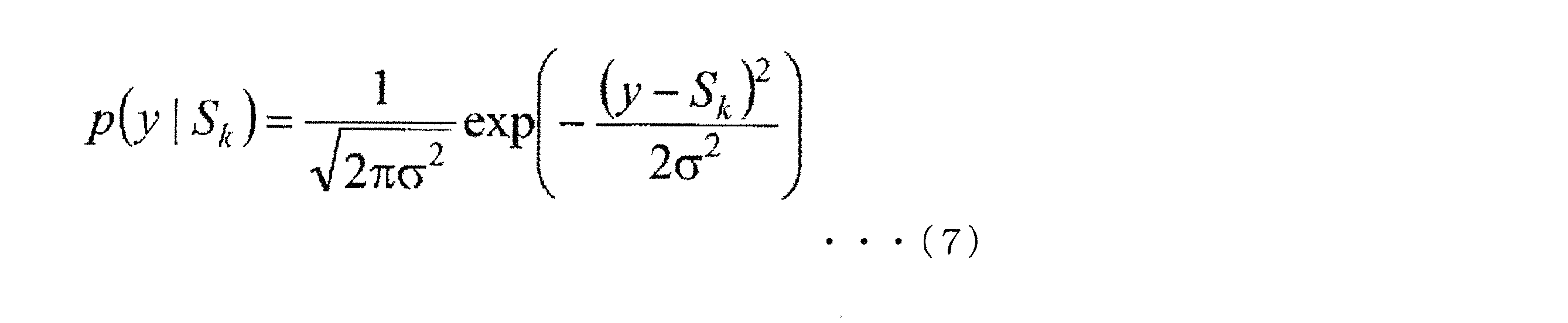

事前情報として、La(bj)が与えられたとすると、式(1)の最後の右辺の第2項より、式(9)であり、式(10)となる。


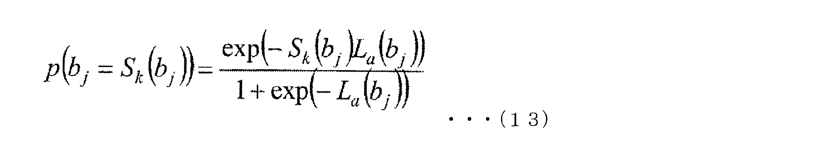
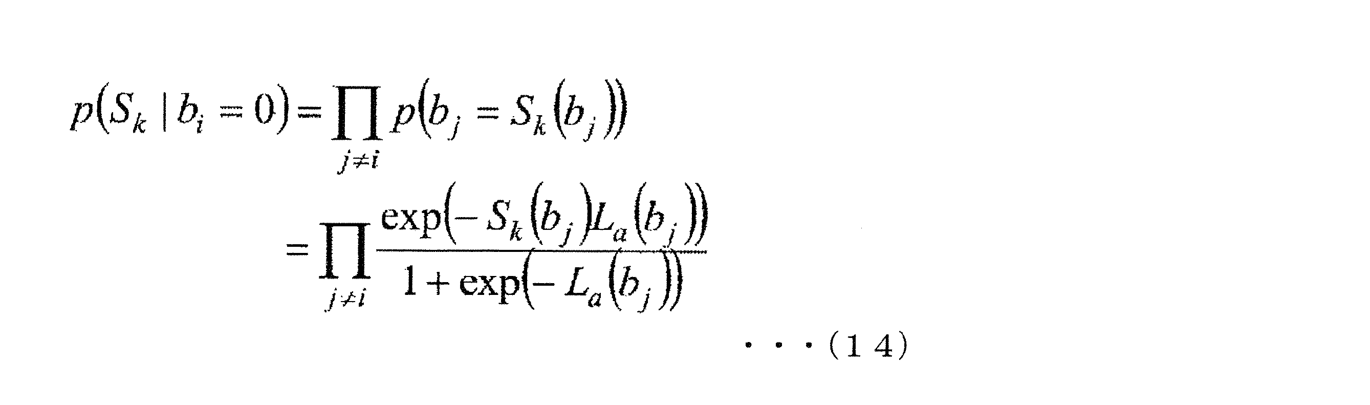
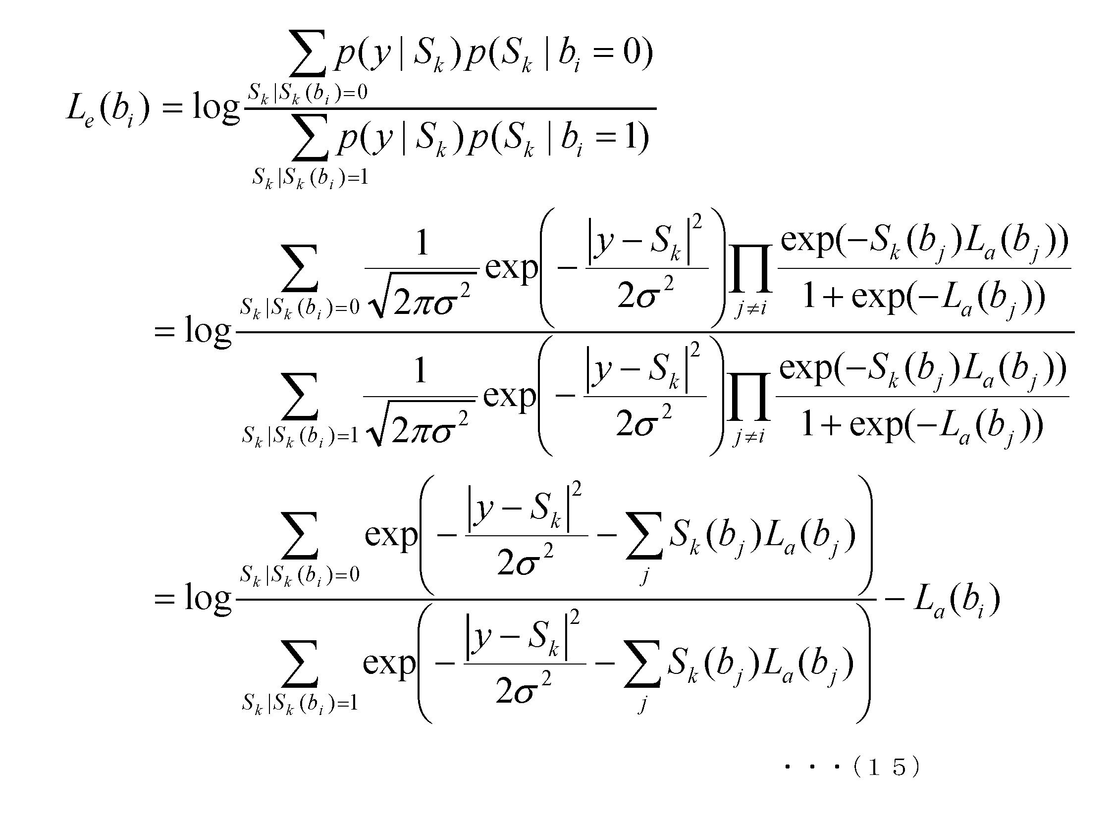
L(u1)が与えられたとすると、式(11)、式(12)より、式(16)、式(17)が成り立つ。

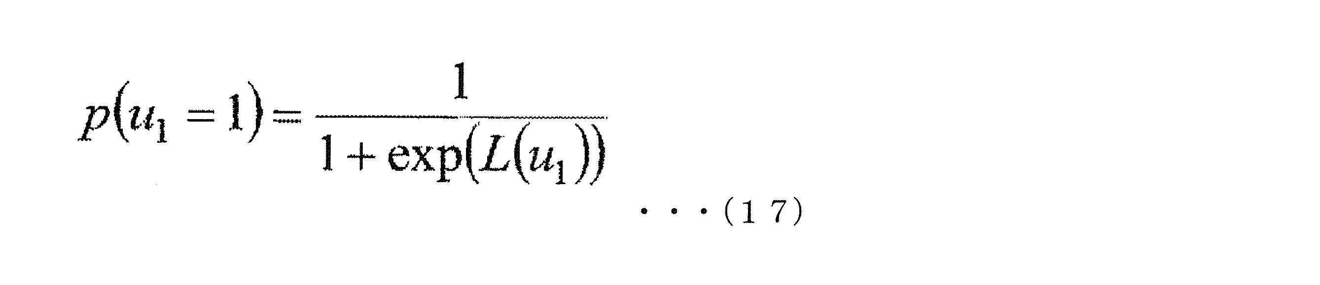
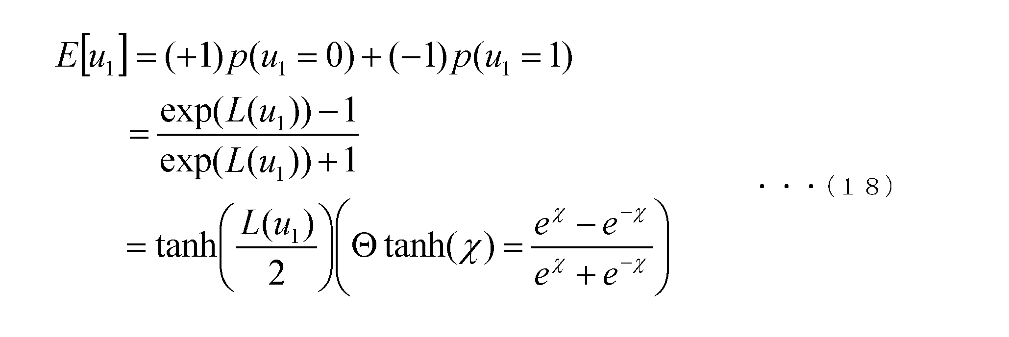



図7は、送信装置の構成図である。
次に、本実施の形態で重要となるマッピング部708が行う(12,4)16APSK、(8,8)16APSKのマッピングの信号点配置と各信号点へのビットの割り付け(ラベリング)について説明する。
信号点1-2[1000]・・・(R2cos(5π/12),R2sin(5π/12))
信号点1-3[1100]・・・(R1cos(π/4),R1sin(π/4))
信号点1-4[0100]・・・(R2cos(π/12),R2sin(π/12))
信号点2-1[0010]・・・(R2cos(3π/4),R2sin(3π/4))
信号点2-2[1010]・・・(R2cos(7π/12),R2sin(7π/12))
信号点2-3[1110]・・・(R1cos(3π/4),R1sin(3π/4))
信号点2-4[0110]・・・(R2cos(11π/12),R2sin(11π/12))
信号点3-1[0011]・・・(R2cos(-3π/4),R2sin(-3π/4))
信号点3-2[1011]・・・(R2cos(-7π/12),R2sin(-7π/12))
信号点3-3[1111]・・・(R1cos(-3π/4),R1sin(-3π/4))
信号点3-4[0111]・・・(R2cos(-11π/12),R2sin(-11π/12))
信号点4-1[0001]・・・(R2cos(-π/4),R2sin(-π/4))
信号点4-2[1001]・・・(R2cos(-5π/12),R2sin(-5π/12))
信号点4-3[1101]・・・(R1cos(-π/4),R1sin(-π/4))
信号点4-4[0101]・・・(R2cos(-π/12),R2sin(-π/12))
信号点1-1[0000]・・・(R2cos(π/4),R2sin(π/4))
と記載しているが、マッピング部708の入力となるデータにおいて、4つのビット[b3b2b1b0]=[0000]のとき、マッピング後のベースバンド信号の同相成分I、直交成分Qが、(I,Q)= (R2cos(π/4),R2sin(π/4))となることを意味している。もう一つの例で、
信号点4-4[0101]・・・(R2cos(-π/12),R2sin(-π/12))
と記載しているが、マッピング部708の入力となるデータにおいて、4つのビット[b3b2b1b0]=[0101]のとき、マッピング後のベースバンド信号の同相成分I、直交成分Qが、(I,Q)= (R2cos(-π/12),R2sin(-π/12))となることを意味している。
信号点1-1、信号点1-2、信号点1-3、信号点1-4、信号点2-1、信号点2-2、信号点2-3、信号点2-4、信号点3-1、信号点3-2、信号点3-3、信号点3-4、信号点4-1、信号点4-2、信号点4-3、信号点4-4についてすべて同様となる。
信号点1-2[0010]・・・(R1cos(3π/8),R1sin(3π/8))
信号点1-3[0110]・・・(R1cos(5π/8),R1sin(5π/8))
信号点1-4[0100]・・・(R1cos(7π/8),R1sin(7π/8))
信号点1-5[1100]・・・(R1cos(-7π/8),R1sin(-7π/8))
信号点1-6[1110]・・・(R1cos(-5π/8),R1sin(-5π/8))
信号点1-7[1010]・・・(R1cos(-3π/8),R1sin(-3π/8))
信号点1-8[1000]・・・(R1cos(-π/8),R1sin(-π/8))
信号点2-1[0001]・・・(R2cos(π/8),R2sin(π/8))
信号点2-2[0011]・・・(R2cos(3π/8),R2sin(3π/8))
信号点2-3[0111]・・・(R2cos(5π/8),R2sin(5π/8))
信号点2-4[0101]・・・(R2cos(7π/8),R2sin(7π/8))
信号点2-5[1101]・・・(R2cos(-7π/8),R2sin(-7π/8))
信号点2-6[1111]・・・(R2cos(-5π/8),R2sin(-5π/8))
信号点2-7[1011]・・・(R2cos(-3π/8),R2sin(-3π/8))
信号点2-8[1001]・・・(R2cos(-π/8),R2sin(-π/8))
信号点1-1[0000]・・・(R1cos(π/8),R1sin(π/8))
と記載しているが、マッピング部708の入力となるデータにおいて、4つのビット[b3b2b1b0]=[0000]のとき、マッピング後のベースバンド信号の同相成分I、直交成分Qが、(I,Q)= (R1cos(π/8),R1sin(π/8))となることを意味している。もう一つの例で、
信号点2-8[1001]・・・(R2cos(-π/8),R2sin(-π/8))
と記載しているが、マッピング部708の入力となるデータにおいて、4つのビット[b3b2b1b0]=[1001]のとき、マッピング後のベースバンド信号の同相成分I、直交成分Qが、(I,Q)= (R2cos(-π/8),R2sin(-π/8))となることを意味している。
信号点1-1、信号点1-2、信号点1-3、信号点1-4、信号点1-5、信号点1-6、信号点1-7、信号点1-8、信号点2-1、信号点2-2、信号点2-3、信号点2-4、信号点2-5、信号点2-6、信号点2-7、信号点2-8についてすべて同様となる。
上述した2種類の変調方式における送信出力を同一にするために、次のような正規化係数を用いることがある。


正規化前のベースバンド信号の同相成分をIb、直交成分をQbとする。そして、正規化後のベースバンド信号の同相成分をIn、直交成分をQnとする。すると、変調方式が(12,4)16APSKのとき、(In, Qn)=(a(12,4)×Ib, a(12,4)×Qb)が成立し、変調方式が(8,8)16APSKのとき、(In, Qn)=(a(8,8)×Ib, a(8,8)×Qb)が成立する。
・・・(In, Qn)=(a(12,4)×R2×cos(π/4), a(12,4)×R2×sin(π/4))
信号点1-2[1000]
・・・(In, Qn)=(a(12,4)×R2×cos(5π/12), a(12,4)×R2×sin(5π/12))
信号点1-3[1100]
・・・(In, Qn)=(a(12,4)×R1×cos(π/4), a(12,4)×R1×sin(π/4))
信号点1-4[0100]
・・・(In, Qn)=(a(12,4)×R2×cos(π/12), a(12,4)×R2×sin(π/12))
信号点2-1[0010]
・・・(In, Qn)=(a(12,4)×R2×cos(3π/4), a(12,4)×R2×sin(3π/4))
信号点2-2[1010]
・・・(In, Qn)=(a(12,4)×R2×cos(7π/12), a(12,4)×R2×sin(7π/12))
信号点2-3[1110]
・・・(In, Qn)=(a(12,4)×R1×cos(3π/4), a(12,4)×R1×sin(3π/4))
信号点2-4[0110]
・・・(In, Qn)=(a(12,4)×R2×cos(11π/12), a(12,4)×R2×sin(11π/12))
信号点3-1[0011]
・・・(In, Qn)=(a(12,4)×R2×cos(-3π/4), a(12,4)×R2×sin(-3π/4))
信号点3-2[1011]
・・・(In, Qn)=(a(12,4)×R2×cos(-7π/12), a(12,4)×R2×sin(-7π/12))
信号点3-3[1111]
・・・(In, Qn)=(a(12,4)×R1×cos(-3π/4), a(12,4)×R1×sin(-3π/4))
信号点3-4[0111]
・・・(In, Qn)=(a(12,4)×R2×cos(-11π/12), a(12,4)×R2×sin(-11π/12))
信号点4-1[0001]
・・・(In, Qn)=(a(12,4)×R2×cos(-π/4), a(12,4)×R2×sin(-π/4))
信号点4-2[1001]
・・・(In, Qn)=(a(12,4)×R2×cos(-5π/12), a(12,4)×R2×sin(-5π/12))
信号点4-3[1101]
・・・(In, Qn)=(a(12,4)×R1×cos(-π/4), a(12,4)×R1×sin(-π/4))
信号点4-4[0101]
・・・(In, Qn)=(a(12,4)×R2×cos(-π/12), a(12,4)×R2×sin(-π/12))
信号点1-1[0000]
・・・(In, Qn)=(a(12,4)×R2×cos(π/4), a(12,4)×R2×sin(π/4))と記載しているが、マッピング部708の入力となるデータにおいて、4つのビット[b3b2b1b0]=[0000]のとき、(In, Qn)=(a(12,4)×R2×cos(π/4), a(12,4)×R2×sin(π/4))となることを意味している。
もう一つの例で、
信号点4-4[0101]
・・・(In, Qn)=(a(12,4)×R2×cos(-π/12), a(12,4)×R2×sin(-π/12))と記載しているが、マッピング部708の入力となるデータにおいて、4つのビット[b3b2b1b0]=[0101]のとき、(In, Qn)=(a(12,4)×R2×cos(-π/12), a(12,4)×R2×sin(-π/12))となることを意味している。
信号点1-1、信号点1-2、信号点1-3、信号点1-4、信号点2-1、信号点2-2、信号点2-3、信号点2-4、信号点3-1、信号点3-2、信号点3-3、信号点3-4、信号点4-1、信号点4-2、信号点4-3、信号点4-4についてすべて同様となる。
同様に、(8,8)16APSKのとき、正規化前のベースバンド信号の同相成分をIb、直交成分をQbは、図9に基づきマッピングすることにより得られたマッピング後のベースバンド信号の同相成分I、直交成分Qとなる。したがって、(8,8)16APSKのとき、以下の関係が成立
する。
・・・(In, Qn)=(a(8,8)×R1×cos(π/8), a(8,8)×R1×sin(π/8))
信号点1-2[0010]
・・・(In, Qn)=(a(8,8)×R1×cos(3π/8), a(8,8)×R1×sin(3π/8))
信号点1-3[0110]
・・・(In, Qn)=(a(8,8)×R1×cos(5π/8), a(8,8)×R1×sin(5π/8))
信号点1-4[0100]
・・・(In, Qn)=(a(8,8)×R1×cos(7π/8), a(8,8)×R1×sin(7π/8))
信号点1-5[1100]
・・・(In, Qn)=(a(8,8)×R1×cos(-7π/8), a(8,8)×R1×sin(-7π/8))
信号点1-6[1110]
・・・(In, Qn)=(a(8,8)×R1×cos(-5π/8), a(8,8)×R1×sin(-5π/8))
信号点1-7[1010]
・・・(In, Qn)=(a(8,8)×R1×cos(-3π/8), a(8,8)×R1×sin(-3π/8))
信号点1-8[1000]
・・・(In, Qn)=(a(8,8)×R1×cos(-π/8), a(8,8)×R1×sin(-π/8))
信号点2-1[0001]
・・・(In, Qn)=(a(8,8)×R2×cos(π/8), a(8,8)×R2×sin(π/8))
信号点2-2[0011]
・・・(In, Qn)=(a(8,8)×R2×cos(3π/8), a(8,8)×R2×sin(3π/8))
信号点2-3[0111]
・・・(In, Qn)=(a(8,8)×R2×cos(5π/8), a(8,8)×R2×sin(5π/8))
信号点2-4[0101]
・・・(In, Qn)=(a(8,8)×R2×cos(7π/8), a(8,8)×R2×sin(7π/8))
信号点2-5[1101]
・・・(In, Qn)=(a(8,8)×R2×cos(-7π/8), a(8,8)×R2×sin(-7π/8))
信号点2-6[1111]
・・・(In, Qn)=(a(8,8)×R2×cos(-5π/8), a(8,8)×R2×sin(-5π/8))
信号点2-7[1011]
・・・(In, Qn)=(a(8,8)×R2×cos(-3π/8), a(8,8)×R2×sin(-3π/8))
信号点2-8[1001]
・・・(In, Qn)=(a(8,8)×R2×cos(-π/8), a(8,8)×R2×sin(-π/8))
信号点1-1[0000]
・・・(In, Qn)=(a(8,8)×R1×cos(π/8), a(8,8)×R1×sin(π/8))と記載しているが、マッピング部708の入力となるデータにおいて、4つのビット[b3b2b1b0]=[0000]のとき、(In, Qn)=(a(8,8)×R1×cos(π/8), a(8,8)×R1×sin(π/8))となることを意味している。もう一つの例で、
信号点2-8[1001]
・・・(In, Qn)=(a(8,8)×R2×cos(-π/8), a(8,8)×R2×sin(-π/8))と記載しているが、マッピング部708の入力となるデータにおいて、4つのビット[b3b2b1b0]=[1001]のとき、(In, Qn)=(a(8,8)×R2×cos(-π/8), a(8,8)×R2×sin(-π/8))となることを意味している。
信号点1-1、信号点1-2、信号点1-3、信号点1-4、信号点1-5、信号点1-6、信号点1-7、信号点1-8、信号点2-1、信号点2-2、信号点2-3、信号点2-4、信号点2-5、信号点2-6、信号点2-7、信号点2-8についてすべて同様となる。
そして、マッピング部708は、上述で説明したIn、Qnをベースバンド信号同相成分、直交成分として出力することになる。
次に、高度広帯域衛星デジタル放送に本実施の形態を適用した場合の変調信号のフレーム構成について説明する。
パイロット送出時:接点1=c,接点2=スロット(またはシンボル)に割り当てられた変調方式によりa~e 選択(なお、本発明の重要な点として、特にシンボル毎にb1,b2を交互に選択する場合がある。この点については、後で詳しく説明する。)
TMCC送出時:接点1=b,接点2=e
データ送出時:接点1=a,接点2=スロット(またはシンボル)に割り当てられた変調方式によりa~e 選択(なお、本発明の重要な点として、特にシンボル毎にb1,b2を交互に(あるいは、規則的に)選択する場合がある。この点については、後で詳しく説明する。)
なお、図11に示す並びとなるようにするための情報は、図10の制御信号に含まれているものとする。
マッピング部708は、制御信号の情報に基づき、選択部1001により選択された方式によりマッピングを行う。
変調部710は、制御信号の情報に基づき、時分割多重・直交変調、ルートロールオフフィルタに依る帯域制限等の処理を行い、変調波を出力する。
上述で説明したように、高度広帯域衛星デジタル放送では、同相I―直交Q平面において、16個の信号点、つまり、1シンボルにより、4ビットを伝送する変調方式として、(12,4)16APSKを採用している。その理由の一つとして、(12,4)16APSKのPAPRが、例えば、16QAMのPAPR, (8,8)16APSKのPAPRより小さく、放送局、つまり、衛星から送信する電波の平均送信電力を大きくすることができるという利点があるからである。よって、(12,4)16APSKは、16QAM、(8,8)16APSKより、BER特性が悪いが、平均送信電力を大きく設定できる点を考慮すると、受信可能なエリアを広く確保できる可能性が高い。(この点については、上述で説明したとおりである。)
「変調方式が(12,4)16APSKまたは(8,8)16APSKのいずれかであるシンボルが、3シンボル以上(または、4シンボル以上)連続するシンボル群において、(12,4)16APSKのシンボルが連続する部分が存在せず、かつ、(8,8)16APSKのシンボルが連続する部分が存在しない。」(ただし、以下で、この変形例について説明しているように、これを満たさない方法でも、上記のシンボル配置例と同様の効果を得ることができる送信方法はある。)
図11で示したData#7855の136シンボルは、図11で示しているように、時間軸方向に「第1番目のシンボル」「第2番目のシンボル」、「第3番目のシンボル」、・・・、「第135番目のシンボル」、「第136番目のシンボル」と並んでいるものとする。
「第51番目のシンボル」で伝送する4ビット[b3b2b1b0]=[1100]であり、図12に示すように●の信号点に相当するベースバンド信号の同相成分および直交成分を送信装置は送信する。(変調方式:(12,4)16APSK)
「第52番目のシンボル」で伝送する4ビット[b3b2b1b0]=[0101]であり、図12に示すように●の信号点に相当するベースバンド信号の同相成分および直交成分を送信装置は送信する。(変調方式:(8,8)16APSK)
「第53番目のシンボル」で伝送する4ビット[b3b2b1b0]=[0011]であり、図12に示すように●の信号点に相当するベースバンド信号の同相成分および直交成分を送信装置は送信する。(変調方式:(12,4)16APSK)
「第54番目のシンボル」で伝送する4ビット[b3b2b1b0]=[0110]であり、図12に示すように●の信号点に相当するベースバンド信号の同相成分および直交成分を送信装置は送信する。(変調方式:(8,8)16APSK)
「第55番目のシンボル」で伝送する4ビット[b3b2b1b0]=[1001]であり、図12に示すように●の信号点に相当するベースバンド信号の同相成分および直交成分を送信装置は送信する。(変調方式:(12,4)16APSK)
「第56番目のシンボル」で伝送する4ビット[b3b2b1b0]=[0010]であり、図12に示すように●の信号点に相当するベースバンド信号の同相成分および直交成分を送信装置は送信する。(変調方式:(8,8)16APSK)
本発明では、I-Q平面において、16個の信号点をもつ変調方式の中でも、特に、PAPRの小さい(12,4)16APSKとPAPRが若干大きい(8,8)16APSKにおいて、「変調方式が(12,4)16APSKまたは(8,8)16APSKのいずれかであるシンボルが、3シンボル以上(または、4シンボル以上)連続するシンボル群において、(12,4)16APSKのシンボルが連続する部分が存在せず、かつ、(8,8)16APSKのシンボルが連続する部分が存在しない。」ようにしている。
同様に、(8,8)16APSKのI-Q平面における信号点をあらわすのに用いたR1とR2より、(8,8)16APSKのリング比R(8,8)をR(8,8)=R2/R1とあらわすものとする。
「変調方式が(12,4)16APSKまたは(8,8)16APSKのいずれかであるシンボルが、3シンボル以上(または、4シンボル以上)連続するシンボル群において、(12,4)16APSKのシンボルが連続する部分が存在せず、かつ、(8,8)16APSKのシンボルが連続する部分が存在しない。」とした場合、ピーク電力を支配する可能性の高い変調方式は、(8,8)16APSKとなる。このとき、(8,8)16APSKで発生するピーク電力は、R(8,8)が大きくなるにつれ、大きくなる可能性が高い。したがって、ピーク電力を大きくしないためには、R(8,8)を小さく設定するとよいことになり、一方、(12,4)16APSKのR(12,4)は、BER特性がよくなる値に設定すればよく自由度が高い。このため、R(8,8)<R(12,4)という関係があるとよい可能性が高くなる。
したがって、BER特性を良くすることに着眼した場合に、R(8,8)>R(12,4)がよい場合もある。
上記、リング比の関係については、以下で説明する変形例(<変調方式等の切換のパターン>)の場合においても、同様である。
以上のように説明した実施の形態によれば、異なる変調方式のシンボルを交互に配置することで、PAPRが小さく、かつ、良好なデータの受信品質の提供に寄与することができる。
[(12,4)16APSKのラベリングについて]
ここでは、(12,4)16APSKのラベリングについて説明を行う。なお、ラベリングとは、入力となる4ビット[b3b2b1b0]と同相I―直交Q平面における信号点の配置の関係のことである。図8に(12,4)16APSKのラベリングの例を示したが、以下の<条件1>かつ<条件2>を満たすラベリングであれば構わない。
伝送する4ビットが[ba3ba2ba1ba0]のとき、同相I―直交Q平面において信号点Aを与えるものとし、伝送する4ビットが[bb3bb2bb1bb0]のとき、同相I―直交Q平面において信号点Bを与えるものとする。
このとき、「ba3=bb3かつba2=bb2かつba1=bb1かつba0=bb0」のときラベリングの異なるビット数を0と定義する。
「ba3≠bb3かつba2=bb2かつba1=bb1かつba0=bb0」のときラベリングの異なるビット数を1と定義する。
「ba3=bb3かつba2≠bb2かつba1=bb1かつba0=bb0」のときラベリングの異なるビット数を1と定義する。
「ba3=bb3かつba2=bb2かつba1≠bb1かつba0=bb0」のときラベリングの異なるビット数を1と定義する。
「ba3=bb3かつba2=bb2かつba1=bb1かつba0≠bb0」のときラベリングの異なるビット数を1と定義する。
「ba3≠bb3かつba2≠bb2かつba1=bb1かつba0=bb0」のときラベリングの異なるビット数を2と定義する。
「ba3≠bb3かつba2=bb2かつba1≠bb1かつba0=bb0」のときラベリングの異なるビット数を2と定義する。
「ba3≠bb3かつba2=bb2かつba1=bb1かつba0≠bb0」のときラベリングの異なるビット数を2と定義する。
「ba3=bb3かつba2≠bb2かつba1≠bb1かつba0=bb0」のときラベリングの異なるビット数を2と定義する。
「ba3=bb3かつba2≠bb2かつba1=bb1かつba0≠bb0」のときラベリングの異なるビット数を2と定義する。
「ba3=bb3かつba2=bb2かつba1≠bb1かつba0≠bb0」のときラベリングの異なるビット数を2と定義する。
「ba3=bb3かつba2≠bb2かつba1≠bb1かつba0≠bb0」のときラベリングの異なるビット数を3と定義する。
「ba3≠bb3かつba2=bb2かつba1≠bb1かつba0≠bb0」のときラベリングの異なるビット数を3と定義する。
「ba3≠bb3かつba2≠bb2かつba1=bb1かつba0≠bb0」のときラベリングの異なるビット数を3と定義する。
「ba3≠bb3かつba2≠bb2かつba1≠bb1かつba0=bb0」のときラベリングの異なるビット数を3と定義する。
「ba3≠bb3かつba2≠bb2かつba1≠bb1かつba0≠bb0」のときラベリングの異なるビット数を4と定義する。
図8の同相I―直交Q平面における(12,4)16APSKのラベリングと信号点配置において「信号点1-1、信号点1-2、信号点1-3、信号点1-4をグループ1」と定義する。同様に「信号点2-1、信号点2-2、信号点2-3、信号点2-4をグループ2」、「信号点3-1、信号点3-2、信号点3-3、信号点3-4をグループ3」、「信号点4-1、信号点4-2、信号点4-3、信号点4-4をグループ4」と定義する。
<条件1>:
Xは1,2,3,4であり、これを満たす、すべてのXで以下が成立する。
信号点X-2と信号点X-3のラベリングの異なるビット数は1
信号点X-3と信号点X-4のラベリングの異なるビット数は1
信号点X-4と信号点X-1のラベリングの異なるビット数は1
外円については、
信号点1-2と信号点2-2のラベリングの異なるビット数は1
信号点3-2と信号点4-2のラベリングの異なるビット数は1
信号点1-4と信号点4-4のラベリングの異なるビット数は1
信号点2-4と信号点3-4のラベリングの異なるビット数は1
が成立し、内円については、
信号点1-3と信号点2-3のラベリングの異なるビット数は1
信号点2-3と信号点3-3のラベリングの異なるビット数は1
信号点3-3と信号点4-3のラベリングの異なるビット数は1
信号点4-3と信号点1-3のラベリングの異なるビット数は1
が成立する。
上述では、図14の同相I―直交Q平面における信号点配置とラベリングについて説明したが、同相I―直交Q平面における信号点配置とラベリングの方法はこれに限ったものではない。例えば、(12,4)16APSK の各信号点のIQ平面上の座標、ラベリングとして、以下のものを考える。
(cosθ×R2×cos(π/4)-sinθ×R2×sin(π/4), sinθ×R2×cos(π/4)+ cosθ×R2×sin(π/4) )
信号点1-2のIQ平面上の座標:
(cosθ×R2×cos(5π/12)-sinθ×R2×sin(5π/12), sinθ×R2×cos(5π/12)+cosθ×R2×sin(5π/12) )
信号点1-3のIQ平面上の座標:
(cosθ×R1×cos(π/4)-sinθ×R1×sin(π/4), sinθ×R1×cos(π/4)+ cosθ×R1×sin(π/4) )
信号点1-4のIQ平面上の座標:
(cosθ×R2×cos(π/12)-sinθ×R2×sin(π/12), sinθ×R2×cos(π/12)+ cosθ×R2×sin(π/12) )
信号点2-1のIQ平面上の座標:
(cosθ×R2×cos(3π/4)-sinθ×R2×sin(3π/4), sinθ×R2×cos(3π/4)+ cosθ× R2×sin(3π/4))
信号点2-2のIQ平面上の座標:
(cosθR2×cos(7π/12)×-sinθ×R2×sin(7π/12), sinθ×R2×cos(7π/12)+ cosθ× R2×sin(7π/12))
信号点2-3のIQ平面上の座標:
(cosθ×R1×cos(3π/4)-sinθ×R1×sin(3π/4), sinθ×R1×cos(3π/4)+ cosθ× R1×sin(3π/4))
信号点2-4のIQ平面上の座標:
(cosθ×R2×cos(11π/12)-sinθ×R2×sin(11π/12), sinθ×R2×cos(11π/12)+cosθ×R2×sin(11π/12) )
信号点3-1のIQ平面上の座標:
(cosθ×R2×cos(-3π/4)-sinθ×R2×sin(-3π/4), sinθ×R2×cos(-3π/4)+cosθ×R2×sin(-3π/4) )
信号点3-2のIQ平面上の座標:
(cosθ×R2×cos(-7π/12)-sinθ×R2×sin(-7π/12), sinθ×R2×cos(-7π/12)+cosθ×R2×sin(-7π/12) )
信号点3-3のIQ平面上の座標:
(cosθ×R1×cos(-3π/4)-sinθ×R1×sin(-3π/4), sinθ×R1×cos(-3π/4)+cosθ×R1×sin(-3π/4) )
信号点3-4のIQ平面上の座標:
(cosθ×R2×cos(-11π/12)-sinθ×R2×sin(-11π/12), sinθ×R2×cos(-11π/12)+cosθ×R2×sin(-11π/12) )
信号点4-1のIQ平面上の座標:
(cosθ×R2×cos(-π/4)-sinθ×R2×sin(-π/4), sinθ×R2×cos(-π/4)+ cosθ× R2×sin(-π/4))
信号点4-2のIQ平面上の座標:
(cosθ×R2×cos(-5π/12)-sinθ×R2×sin(-5π/12), sinθ×R2×cos(-5π/12)+cosθ×R2×sin(-5π/12) )
信号点4-3のIQ平面上の座標:
(cosθ×R1×cos(-π/4)-sinθ×R1×sin(-π/4), sinθ×R1×cos(-π/4)+ cosθ× R1×sin(-π/4))
信号点4-4のIQ平面上の座標:
(cosθ×R2×cos(-π/12)-sinθ×R2×sin(-π/12), sinθ×R2×cos(-π/12)+ cosθ×R2×sin(-π/12))
(In, Qn)=(a(12,4)×cosθ×R2×cos(π/4)- a(12,4)×sinθ×R2×sin(π/4), a(12,4)×sinθ×R2×cos(π/4)+ a(12,4)×cosθ×R2×sin(π/4) )
信号点1-2のIQ平面上の座標:
(In, Qn)=(a(12,4)×cosθ×R2×cos(5π/12)- a(12,4)×sinθ×R2×sin(5π/12), a(12,4)×sinθ×R2×cos(5π/12)+ a(12,4)×cosθ×R2×sin(5π/12) )
信号点1-3のIQ平面上の座標:
(In, Qn)=(a(12,4)×cosθ×R1×cos(π/4)- a(12,4)×sinθ×R1×sin(π/4), a(12,4)×sinθ×R1×cos(π/4)+ a(12,4)×cosθ×R1×sin(π/4) )
信号点1-4のIQ平面上の座標:
(In, Qn)=(a(12,4)×cosθ×R2×cos(π/12)- a(12,4)×sinθ×R2×sin(π/12), a(12,4)×sinθ×R2×cos(π/12)+ a(12,4)× cosθ×R2×sin(π/12) )
信号点2-1のIQ平面上の座標:
(In, Qn)=(a(12,4)×cosθ×R2×cos(3π/4)- a(12,4)×sinθ×R2×sin(3π/4), a(12,4)×sinθ×R2×cos(3π/4)+ a(12,4)×cosθ× R2×sin(3π/4))
信号点2-2のIQ平面上の座標:
(In, Qn)=(a(12,4)×cosθR2×cos(7π/12)×- a(12,4)×sinθ×R2×sin(7π/12), a(12,4)×sinθ×R2×cos(7π/12)+ a(12,4)×cosθ× R2×sin(7π/12))
信号点2-3のIQ平面上の座標:
(In, Qn)=(a(12,4)×cosθ×R1×cos(3π/4)- a(12,4)×sinθ×R1×sin(3π/4), a(12,4)×sinθ×R1×cos(3π/4)+ a(12,4)×cosθ× R1×sin(3π/4))
信号点2-4のIQ平面上の座標:
(In, Qn)=(a(12,4)×cosθ×R2×cos(11π/12)- a(12,4)×sinθ×R2×sin(11π/12), a(12,4)×sinθ×R2×cos(11π/12)+ a(12,4)×cosθ×R2×sin(11π/12) )
信号点3-1のIQ平面上の座標:
(In, Qn)=(a(12,4)×cosθ×R2×cos(-3π/4)- a(12,4)×sinθ×R2×sin(-3π/4), a(12,4)×sinθ×R2×cos(-3π/4)+ a(12,4)×cosθ×R2×sin(-3π/4) )
信号点3-2のIQ平面上の座標:
(In, Qn)=(a(12,4)×cosθ×R2×cos(-7π/12)- a(12,4)×sinθ×R2×sin(-7π/12), a(12,4)×sinθ×R2×cos(-7π/12)+ a(12,4)×cosθ×R2×sin(-7π/12) )
信号点3-3のIQ平面上の座標:
(In, Qn)=(a(12,4)×cosθ×R1×cos(-3π/4)- a(12,4)×sinθ×R1×sin(-3π/4), a(12,4)×sinθ×R1×cos(-3π/4)+ a(12,4)×cosθ×R1×sin(-3π/4) )
信号点3-4のIQ平面上の座標:
(In, Qn)=(a(12,4)×cosθ×R2×cos(-11π/12)- a(12,4)×sinθ×R2×sin(-11π/12), a(12,4)×sinθ×R2×cos(-11π/12)+ a(12,4)×cosθ×R2×sin(-11π/12) )
信号点4-1のIQ平面上の座標:
(In, Qn)=(a(12,4)×cosθ×R2×cos(-π/4)- a(12,4)×sinθ×R2×sin(-π/4), a(12,4)×sinθ×R2×cos(-π/4)+ a(12,4)×cosθ× R2×sin(-π/4))
信号点4-2のIQ平面上の座標:
(In, Qn)=(a(12,4)×cosθ×R2×cos(-5π/12)- a(12,4)×sinθ×R2×sin(-5π/12), a(12,4)×sinθ×R2×cos(-5π/12)+ a(12,4)×cosθ×R2×sin(-5π/12) )
信号点4-3のIQ平面上の座標:
(In, Qn)=(a(12,4)×cosθ×R1×cos(-π/4)- a(12,4)×sinθ×R1×sin(-π/4), a(12,4)×sinθ×R1×cos(-π/4)+ a(12,4)× cosθ× R1×sin(-π/4))
信号点4-4のIQ平面上の座標:
(In, Qn)=(a(12,4)×cosθ×R2×cos(-π/12)- a(12,4)×sinθ×R2×sin(-π/12), a(12,4)×sinθ×R2×cos(-π/12)+ a(12,4)×cosθ× R2×sin(-π/12))
そして、「変調方式が(12,4)16APSKまたは(8,8)16APSKのいずれかであるシンボルが、3シンボル以上(または、4シンボル以上)連続するシンボル群において、(12,4)16APSKのシンボルが連続する部分が存在せず、かつ、(8,8)16APSKのシンボルが連続する部分が存在しない。」方式において、(12,4)16APSK の各信号点のIQ平面上の座標が上述で与えられ、かつ、<条件1>および<条件2>を満たす(12,4)16APSKであってもよい。
[(8,8)16APSKのラベリングについて]
ここでは、(8,8)16APSKのラベリングについて説明を行う。図9に(8,8)16APSKのラベリングの例を示したが、以下の<条件3>かつ<条件4>を満たすラベリングであれば構わない。
図16に示すように、
内円の円周上の8点の信号点「信号点1-1、信号点1-2、信号点1-3、信号点1-4、信号点1-5、信号点1-6、信号点1-7、信号点1-8」をグループ1と定義する。そして、外円の円周上の8点の信号点「信号点2-1、信号点2-2、信号点2-3、信号点2-4、信号点2-5、信号点2-6、信号点2-7、信号点2-8」をグループ2と定義する。
<条件3>:
Xは1,2であり、これを満たす、すべてのXで以下が成立する。
信号点X-2と信号点X-3のラベリングの異なるビット数は1
信号点X-3と信号点X-4のラベリングの異なるビット数は1
信号点X-4と信号点X-5のラベリングの異なるビット数は1
信号点X-5と信号点X-6のラベリングの異なるビット数は1
信号点X-6と信号点X-7のラベリングの異なるビット数は1
信号点X-7と信号点X-8のラベリングの異なるビット数は1
信号点X-8と信号点X-1のラベリングの異なるビット数は1
なお、ラベリングの異なるビット数の定義については、上述で説明したとおりである。
Zは1,2,3,4,5,6,7,8であり、これを満たす、すべてのZで以下が成立する。
信号点1-Zと信号点2-Zのラベリングの異なるビット数は1
以上をみたすことで、同相I―直交Q平面において、各信号点にとって近い距離にある信号点とのラベリングの異なるビット数が小さいため、受信装置は高いデータの受信品質を得ることができる可能性が高くなる。そして、これにより、受信装置が反復検波を行った際、高いデータの受信品質を得ることができる可能性が高くなる。
上述では、図16の同相I―直交Q平面における信号点配置とラベリングについて説明したが、同相I―直交Q平面における信号点配置とラベリングの方法はこれに限ったものではない。例えば、(8,8)16APSK の各信号点のIQ平面上の座標、ラベリングとして、以下のものを考える。
(cosθ×R1×cos(π/8)-sinθ×R1×sin(π/8), sinθ×R1×cos(π/8)+ cosθ×R1×sin(π/8))
信号点1-2のIQ平面上の座標:
(cosθ×R1×cos(3π/8)-sinθ×R1×sin(3π/8), sinθ×R1×cos(3π/8)+ cosθ×R1×sin(3π/8))
信号点1-3のIQ平面上の座標:
(cosθ×R1×cos(5π/8)-sinθ×R1×sin(5π/8), sinθ×R1×cos(5π/8)+ cosθ×R1×sin(5π/8))
信号点1-4のIQ平面上の座標:
(cosθ×R1×cos(7π/8)-sinθ×R1×sin(7π/8), sinθ×R1×cos(7π/8)+ cosθ×R1×sin(7π/8))
信号点1-5のIQ平面上の座標:
(cosθ×R1×cos(-7π/8)-sinθ×R1×sin(-7π/8), sinθ×R1×cos(-7π/8)+cosθ×R1×sin(-7π/8))
信号点1-6のIQ平面上の座標:
(cosθ×R1×cos(-5π/8)-sinθ×R1×sin(-5π/8), sinθ×R1×cos(-5π/8)+cosθ×R1×sin(-5π/8))
信号点1-7のIQ平面上の座標:
(cosθ×R1×cos(-3π/8)-sinθ×R1×sin(-3π/8), sinθ×R1×cos(-3π/8)+cosθ×R1×sin(-3π/8))
信号点1-8のIQ平面上の座標:
(cosθ×R1×cos(-π/8)-sinθ×R1×sin(-π/8), sinθ×R1×cos(-π/8)+ cosθ×R1×sin(-π/8))
信号点2-1のIQ平面上の座標:
(cosθ×R2×cos(π/8)-sinθ×R2×sin(π/8), sinθ×R2×cos(π/8)+ cosθ×R2×sin(π/8))
信号点2-2のIQ平面上の座標:
(cosθ×R2×cos(3π/8)-sinθ×R2×sin(3π/8), sinθ×R2×cos(3π/8)+ cosθ×R2×sin(3π/8))
信号点2-3のIQ平面上の座標:
(cosθ×R2×cos(5π/8)-sinθ×R2×sin(5π/8), sinθ×R2×cos(5π/8)+ cosθ×R2×sin(5π/8))
信号点2-4のIQ平面上の座標:
(cosθ×R2×cos(7π/8)-sinθ×R2×sin(7π/8), sinθ×R2×cos(7π/8)+ cosθ×R2×sin(7π/8))
信号点2-5のIQ平面上の座標:
(cosθ×R2×cos(-7π/8)-sinθ×R2×sin(-7π/8), sinθ×R2×cos(-7π/8)+cosθ×R2×sin(-7π/8))
信号点2-6のIQ平面上の座標:
(cosθ×R2×cos(-5π/8)-sinθ×R2×sin(-5π/8), sinθ×R2×cos(-5π/8)+cosθ×R2×sin(-5π/8))
信号点2-7のIQ平面上の座標:
(cosθ×R2×cos(-3π/8)-sinθ×R2×sin(-3π/8), sinθ×R2×cos(-3π/8)+cosθ×R2×sin(-3π/8))
信号点2-8のIQ平面上の座標:
(cosθ×R2×cos(-π/8)-sinθ×R2×sin(-π/8), sinθ×R2×cos(-π/8)+ cosθ×R2×sin(-π/8))
(In, Qn)=(a(8,8)×cosθ×R1×cos(π/8)- a(8,8)×sinθ×R1×sin(π/8), a(8,8)×sinθ×R1×cos(π/8)+ a(8,8)×cosθ×R1×sin(π/8))
信号点1-2のIQ平面上の座標:
(In, Qn)=(a(8,8)×cosθ×R1×cos(3π/8)- a(8,8)×sinθ×R1×sin(3π/8), a(8,8)×sinθ×R1×cos(3π/8)+a(8,8)×cosθ×R1×sin(3
π/8))
信号点1-3のIQ平面上の座標:
(In, Qn)=(a(8,8)×cosθ×R1×cos(5π/8)- a(8,8)×sinθ×R1×sin(5π/8), a(8,8)×sinθ×R1×cos(5π/8)+ a(8,8)×cosθ×R1×sin(5π/8))
信号点1-4のIQ平面上の座標:
(In, Qn)=(a(8,8)×cosθ×R1×cos(7π/8)- a(8,8)×sinθ×R1×sin(7π/8), a(8,8)×sinθ×R1×cos(7π/8)+ a(8,8)×cosθ×R1×sin(7π/8))
信号点1-5のIQ平面上の座標:
(In, Qn)=(a(8,8)×cosθ×R1×cos(-7π/8)- a(8,8)×sinθ×R1×sin(-7π/8), a(8,8)×sinθ×R1×cos(-7π/8)+ a(8,8)×cosθ×R1×sin(-7π/8))
信号点1-6のIQ平面上の座標:
(In, Qn)=(a(8,8)×cosθ×R1×cos(-5π/8)- a(8,8)×sinθ×R1×sin(-5π/8), a(8,8)×sinθ×R1×cos(-5π/8)+ a(8,8)×cosθ×R1×sin(-5π/8))
信号点1-7のIQ平面上の座標:
(In, Qn)=(a(8,8)×cosθ×R1×cos(-3π/8)- a(8,8)×sinθ×R1×sin(-3π/8), a(8,8)×sinθ×R1×cos(-3π/8)+ a(8,8)×cosθ×R1×sin(-3π/8))
信号点1-8のIQ平面上の座標:
(In, Qn)=(a(8,8)×cosθ×R1×cos(-π/8)- a(8,8)×sinθ×R1×sin(-π/8), a(8,8)×sinθ×R1×cos(-π/8)+ a(8,8)×cosθ×R1×sin(-π/8))
信号点2-1のIQ平面上の座標:
(In, Qn)=(a(8,8)×cosθ×R2×cos(π/8)- a(8,8)×sinθ×R2×sin(π/8), a(8,8)×sinθ×R2×cos(π/8)+ a(8,8)×cosθ×R2×sin(π/8))
信号点2-2のIQ平面上の座標:
(In, Qn)=(a(8,8)×cosθ×R2×cos(3π/8)- a(8,8)×sinθ×R2×sin(3π/8), a(8,8)×sinθ×R2×cos(3π/8)+ a(8,8)×cosθ×R2×sin(3π/8))
信号点2-3のIQ平面上の座標:
(In, Qn)=(a(8,8)×cosθ×R2×cos(5π/8)- a(8,8)×sinθ×R2×sin(5π/8), a(8,8)×sinθ×R2×cos(5π/8)+ a(8,8)×cosθ×R2×sin(5π/8))
信号点2-4のIQ平面上の座標:
(In, Qn)=(a(8,8)×cosθ×R2×cos(7π/8)- a(8,8)×sinθ×R2×sin(7π/8), a(8,8)×sinθ×R2×cos(7π/8)+ a(8,8)×cosθ×R2×sin(7π/8))
信号点2-5のIQ平面上の座標:
(In, Qn)=(a(8,8)×cosθ×R2×cos(-7π/8)- a(8,8)×sinθ×R2×sin(-7π/8), a(8,8)×sinθ×R2×cos(-7π/8)+ a(8,8)×cosθ×R2×sin(-7π/8))
信号点2-6のIQ平面上の座標:
(In, Qn)=(a(8,8)×cosθ×R2×cos(-5π/8)- a(8,8)×sinθ×R2×sin(-5π/8), a(8,8)×sinθ×R2×cos(-5π/8)+ a(8,8)×cosθ×R2×sin(-5π/8))
信号点2-7のIQ平面上の座標:
(In, Qn)=(a(8,8)×cosθ×R2×cos(-3π/8)- a(8,8)×sinθ×R2×sin(-3π/8), a(8,8)×sinθ×R2×cos(-3π/8)+ a(8,8)×cosθ×R2×sin(-3π/8))
信号点2-8のIQ平面上の座標:
(In, Qn)=(a(8,8)×cosθ×R2×cos(-π/8)- a(8,8)×sinθ×R2×sin(-π/8), a(8,8)×sinθ×R2×cos(-π/8)+ a(8,8)×cosθ×R2×sin(-π/8))
そして、「変調方式が(12,4)16APSKまたは(8,8)16APSKのいずれかであるシンボルが、3シンボル以上(または、4シンボル以上)連続するシンボル群において、(12,4)16APSKのシンボルが連続する部分が存在せず、かつ、(8,8)16APSKのシンボルが連続する部分が存在しない。」方式において、(8,8)16APSKの各信号点のIQ平面上の座標が上述で与えられ、かつ、<条件3>および<条件4>を満たす(8,8)16APSKであってもよい。
図12の例では、(12,4)16APSKのシンボルと(8,8)16APSKのシンボルとを交互に切り換える((12,4)16APSKのシンボルが連続することがなく、かつ、(8,8)16APSKのシンボルが連続することがない)例を説明した。以下では、上記方式の変形例について説明する。
変形例の特徴は、以下のとおりである。
・1周期は連続するM個のシンボルで構成されている。なお、以降の説明のために、1周期を構成する連続するM個のシンボルのことを「周期Mのシンボル群」と名付ける(定義する)。なお、以降で、図23を用いて説明する。
・連続するシンボルがM+1シンボル以上の場合、「周期Mのシンボル群」を複数個並べることになる。なお、この点については、図24を用いて以降で説明する。
図23に、「周期M=5のシンボル群」の場合のシンボル群の構成の一例を示す。図23における特徴は以下の2つを満たすことである。
・「周期M=5のシンボル群」において、(8,8)16APSKのシンボル数は、(12,4)16APSKのシンボル数より1多い、つまり、(12,4)16APSKのシンボル数は2であり、(8,8)16APSKのシンボル数は3となる。
・「周期M=5のシンボル群」において、(8,8)16APSKのシンボルが2シンボル連続するところがない、または、(8,8)16APSKのシンボルが2シンボル連続するところが1箇所存在する。(よって、(8,8)16APSKのシンボルが3シンボル以上連続するところは存在しない。)
・「周期Mのシンボル群」において、(8,8)16APSKのシンボル数は、(12,4)16APSKのシンボル数より1多い、つまり、(12,4)16APSKのシンボル数はNであり、(8,8)16APSKのシンボル数はN+1となる。なお、Nは自然数となる。
・「周期Mのシンボル群」において、(8,8)16APSKのシンボルが2シンボル連続するところがない、または、(8,8)16APSKのシンボルが2シンボル連続するところが1箇所存在する。(よって、(8,8)16APSKのシンボルが3シンボル以上連続するところは存在しない。)
・データシンボルが(12,4)16APSKのシンボル、(8,8)16APSKのシンボルのいずれかである場合、連続するデータシンボル群において、(8,8)16APSKのシンボルが3シンボル以上連続するところは存在しない。
上述のようにした場合、(8,8)16APSKのシンボルが2個連続する場合があるが、(8,8)16APSKのPAPRよりPAPRを小さくすることができるという効果を得ることができ、また、(12,4)16APSKより、データの受信品質を向上させることができるという効果を得ることができる。
2402、2405、2408、2411は「周期Mのシンボル群」の中間シンボル群である(「周期Mのシンボル群」において、最初のシンボルと最後のシンボルを除くシンボル群である)。
図24(b)の特徴的な点は、「その他のシンボル群」2409の後に、「周期Mのシンボル群」の中間シンボル群の残りの一部2408-2、そのあとに、「周期Mのシンボル群」の最後のシンボル2413を配置する点である。なお、「周期Mのシンボル群」の最初のシンボル2407、「周期Mのシンボル群」の中間シンボル群の一部2408、「周期Mのシンボル群」の中間シンボル群の残りの一部2408-2、「周期Mのシンボル群」の最後のシンボル2413により、「周期Mのシンボル群」を形成することになる。
「周期Mのシンボル群」の最後のシンボル2413の後に、「周期Mのシンボル群」の最初のシンボル2414、「周期Mのシンボル群」の中間シンボル群2415、「周期Mのシンボル群」の最後のシンボル2416で構成される「周期Mのシンボル群」が配置される。
これまで説明した例では、切換に用いる変調方式として16APSKを例に挙げたが、32APSK、64APSKのときも同様に実施することができる。
・同相I-直交Q平面において第1の信号点配置の第1の変調方式のシンボルおよび同相I-直交Q平面において第2の信号点配置の第2の変調方式のシンボルで「周期Mのシンボル群」で構成する。(ただし、第1の変調方式の同相I-直交Q平面における信号点の数と第2の変調方式の同相I-直交Q平面における信号点の数は等しい。)
・同相I-直交Q平面において第1の信号点配置の第1の変調方式または同相I-直交Q平面において第2の信号点配置の第2の変調方式のいずれかであるシンボルが、3シンボル以上(または、4シンボル以上)連続するシンボル群において、第1の変調方式のシンボルが連続する部分が存在せず、かつ、第2の変調方式のシンボル連続する部分が存在しない。」構成する(ただし、第1の変調方式の同相I-直交Q平面における信号点の数と第2の変調方式の同相I-直交Q平面における信号点の数は等しい。)とする。
上記の2種類の連続するシンボルの構成方法において、同相I-直交Q平面における信号点の数が32の二つの32APSKの方式の同相I-直交Q平面における信号点配置を図25に示す。
加えて、(4,12,16)32APSK、(8,8,16)32APSK、(16,16)32APSKと信号点配置の異なるγ方式の32APSKを考える。そして、図25(a)の(4,12,16)32APSK、γ方式の32APSKにより、上記の2種類の連続するシンボルの構成方法を実現してもよい。(つまり、上記の2種類の連続するシンボルの構成方法において、第1の変調方式、第2の変調方式は(4,12,16)32APSKとγ方式の32APSKとなる。)
<パイロットシンボルの例>
本実施の形態では、上記の実施の形態1で説明した送信方式におけるパイロットシンボルの構成例について説明する。
送信装置の電力増幅器の非線形性から、変調信号は、符号間(シンボル間)干渉が発生する。受信装置では、この符号間干渉を低減させることで、高いデータの受信品質を得ることができる。
「変調方式が(12,4)16APSKまたは(8,8)16APSKのいずれかであるシンボルが、3シンボル以上(または、4シンボル以上)連続するシンボル群において、(12,4)16APSKのシンボルが連続する部分が存在せず、かつ、(8,8)16APSKのシンボルが連続する部分が存在しない。」
が成立する場合、(12,4)16APSKが取り得る同相I―直交Q平面のすべての信号点に相当するベースバンド信号(つまり、伝送する4ビット[b3b2b1b0]が[0000]から[1111]の16個の信号点に相当するベースバンド信号)、および、(8,8)16APSKが取り得る同相I―直交Q平面のすべての信号点に相当するベースバンド信号(つまり、伝送する4ビット[b3b2b1b0]が[0000]から[1111]の16個の信号点に相当するベースバンド信号)を発生させ、パイロットシンボルとして送信する方法を提案する。
(12,4)16APSKの[b3b2b1b0]=[0000]に対応する信号点(ベースバンド信号)のシンボル、(8,8)16APSKの[b3b2b1b0]=[0000]に対応する信号点(ベースバンド信号)のシンボル、
(12,4)16APSKの[b3b2b1b0]=[0001]に対応する信号点(ベースバンド信号)のシンボル、(8,8)16APSKの[b3b2b1b0]=[0001]に対応する信号点(ベースバンド信号)のシンボル、
(12,4)16APSKの[b3b2b1b0]=[0010]に対応する信号点(ベースバンド信号)のシンボル、(8,8)16APSKの[b3b2b1b0]=[0010]に対応する信号点(ベースバンド信号)のシンボル、
(12,4)16APSKの[b3b2b1b0]=[0011]に対応する信号点(ベースバンド信号)のシンボル、(8,8)16APSKの[b3b2b1b0]=[0011]に対応する信号点(ベースバンド信号)のシンボル、
(12,4)16APSKの[b3b2b1b0]=[0100]に対応する信号点(ベースバンド信号)のシンボル、(8,8)16APSKの[b3b2b1b0]=[0100]に対応する信号点(ベースバンド信号)のシンボル、
(12,4)16APSKの[b3b2b1b0]=[0101]に対応する信号点(ベースバンド信号)のシンボル、(8,8)16APSKの[b3b2b1b0]=[0101]に対応する信号点(ベースバンド信号)のシンボル、
(12,4)16APSKの[b3b2b1b0]=[0110]に対応する信号点(ベースバンド信号)のシンボル、(8,8)16APSKの[b3b2b1b0]=[0110]に対応する信号点(ベースバンド信号)のシンボル、
(12,4)16APSKの[b3b2b1b0]=[0111]に対応する信号点(ベースバンド信号)のシンボル、(8,8)16APSKの[b3b2b1b0]=[0111]に対応する信号点(ベースバンド信号)のシンボル、
(12,4)16APSKの[b3b2b1b0]=[1000]に対応する信号点(ベースバンド信号)のシンボル、(8,8)16APSKの[b3b2b1b0]=[1000]に対応する信号点(ベースバンド信号)のシンボル、
(12,4)16APSKの[b3b2b1b0]=[1001]に対応する信号点(ベースバンド信号)のシンボル、(8,8)16APSKの[b3b2b1b0]=[1001]に対応する信号点(ベースバンド信号)のシンボル、
(12,4)16APSKの[b3b2b1b0]=[1010]に対応する信号点(ベースバンド信号)のシンボル、(8,8)16APSKの[b3b2b1b0]=[1010]に対応する信号点(ベースバンド信号)のシンボル、
(12,4)16APSKの[b3b2b1b0]=[1011]に対応する信号点(ベースバンド信号)のシンボル、(8,8)16APSKの[b3b2b1b0]=[1011]に対応する信号点(ベースバンド信号)のシンボル、
(12,4)16APSKの[b3b2b1b0]=[1100]に対応する信号点(ベースバンド信号)のシンボル、(8,8)16APSKの[b3b2b1b0]=[1100]に対応する信号点(ベースバンド信号)のシンボル、
(12,4)16APSKの[b3b2b1b0]=[1101]に対応する信号点(ベースバンド信号)のシンボル、(8,8)16APSKの[b3b2b1b0]=[1101]に対応する信号点(ベースバンド信号)のシンボル、
(12,4)16APSKの[b3b2b1b0]=[1110]に対応する信号点(ベースバンド信号)のシンボル、(8,8)16APSKの[b3b2b1b0]=[1110]に対応する信号点(ベースバンド信号)のシンボル、
(12,4)16APSKの[b3b2b1b0]=[1111]に対応する信号点(ベースバンド信号)のシンボル、(8,8)16APSKの[b3b2b1b0]=[1111]に対応する信号点(ベースバンド信号)のシンボル、
をパイロットシンボルとして送信する。
<1>(12,4)16APSKが取り得る同相I―直交Q平面のすべての信号点に相当するシンボル、つまり、
(12,4)16APSKの[b3b2b1b0]=[0000]に対応する信号点(ベースバンド信号)のシンボル、
(12,4)16APSKの[b3b2b1b0]=[0001]に対応する信号点(ベースバンド信号)のシンボル、
(12,4)16APSKの[b3b2b1b0]=[0010]に対応する信号点(ベースバンド信号)のシンボル、
(12,4)16APSKの[b3b2b1b0]=[0011]に対応する信号点(ベースバンド信号)のシンボル、
(12,4)16APSKの[b3b2b1b0]=[0100]に対応する信号点(ベースバンド信号)のシンボル、
(12,4)16APSKの[b3b2b1b0]=[0101]に対応する信号点(ベースバンド信号)のシンボル、
(12,4)16APSKの[b3b2b1b0]=[0110]に対応する信号点(ベースバンド信号)のシンボル、
(12,4)16APSKの[b3b2b1b0]=[0111]に対応する信号点(ベースバンド信号)のシンボル、
(12,4)16APSKの[b3b2b1b0]=[1000]に対応する信号点(ベースバンド信号)のシンボル、
(12,4)16APSKの[b3b2b1b0]=[1001]に対応する信号点(ベースバンド信号)のシンボル、
(12,4)16APSKの[b3b2b1b0]=[1010]に対応する信号点(ベースバンド信号)のシンボル、
(12,4)16APSKの[b3b2b1b0]=[1011]に対応する信号点(ベースバンド信号)のシンボル、
(12,4)16APSKの[b3b2b1b0]=[1100]に対応する信号点(ベースバンド信号)のシンボル、
(12,4)16APSKの[b3b2b1b0]=[1101]に対応する信号点(ベースバンド信号)のシンボル、
(12,4)16APSKの[b3b2b1b0]=[1110]に対応する信号点(ベースバンド信号)のシンボル、
(12,4)16APSKの[b3b2b1b0]=[1111]に対応する信号点(ベースバンド信号)のシンボル、
を送信するとともに、
(8,8)16APSKが取り得る同相I―直交Q平面のすべての信号点に相当するシンボル、
つまり、
(8,8)16APSKの[b3b2b1b0]=[0000]に対応する信号点(ベースバンド信号)のシンボル、
(8,8)16APSKの[b3b2b1b0]=[0001]に対応する信号点(ベースバンド信号)のシンボル、
(8,8)16APSKの[b3b2b1b0]=[0010]に対応する信号点(ベースバンド信号)のシンボル、
(8,8)16APSKの[b3b2b1b0]=[0011]に対応する信号点(ベースバンド信号)のシンボル、
(8,8)16APSKの[b3b2b1b0]=[0100]に対応する信号点(ベースバンド信号)のシンボル、
(8,8)16APSKの[b3b2b1b0]=[0101]に対応する信号点(ベースバンド信号)のシンボル、
(8,8)16APSKの[b3b2b1b0]=[0110]に対応する信号点(ベースバンド信号)のシンボル、
(8,8)16APSKの[b3b2b1b0]=[0111]に対応する信号点(ベースバンド信号)のシンボル、
(8,8)16APSKの[b3b2b1b0]=[1000]に対応する信号点(ベースバンド信号)のシンボル、
(8,8)16APSKの[b3b2b1b0]=[1001]に対応する信号点(ベースバンド信号)のシンボル、
(8,8)16APSKの[b3b2b1b0]=[1010]に対応する信号点(ベースバンド信号)のシンボル、
(8,8)16APSKの[b3b2b1b0]=[1011]に対応する信号点(ベースバンド信号)のシンボル、
(8,8)16APSKの[b3b2b1b0]=[1100]に対応する信号点(ベースバンド信号)のシンボル、
(8,8)16APSKの[b3b2b1b0]=[1101]に対応する信号点(ベースバンド信号)のシンボル、
(8,8)16APSKの[b3b2b1b0]=[1110]に対応する信号点(ベースバンド信号)のシンボル、
(8,8)16APSKの[b3b2b1b0]=[1111]に対応する信号点(ベースバンド信号)のシンボル、
を送信する。
図2において210は受信装置の構成である。図2のデマッピング部214は、送信装置が用いた変調方式のマッピングに対し、デマッピングを行い、例えば、各ビットの対数尤度比を求め、出力する。このとき、図2には図示していないが、デマッピングを精度良く行うためには、符号間干渉の推定、、送信装置と受信装置間の電波の伝搬環境の推定(チャネル推定)、送受信機間の時間同期・周波数オフセットの推定をするとよい。
(12,4)16APSKの[b3b2b1b0]=[0000]に対応する信号点(ベースバンド信号)のシンボル、
(12,4)16APSKの[b3b2b1b0]=[0001]に対応する信号点(ベースバンド信号)のシンボル、
(12,4)16APSKの[b3b2b1b0]=[0010]に対応する信号点(ベースバンド信号)のシンボル、
(12,4)16APSKの[b3b2b1b0]=[0011]に対応する信号点(ベースバンド信号)のシンボル、
(12,4)16APSKの[b3b2b1b0]=[0100]に対応する信号点(ベースバンド信号)のシンボル、
(12,4)16APSKの[b3b2b1b0]=[0101]に対応する信号点(ベースバンド信号)のシンボル、
(12,4)16APSKの[b3b2b1b0]=[0110]に対応する信号点(ベースバンド信号)のシンボル、
(12,4)16APSKの[b3b2b1b0]=[0111]に対応する信号点(ベースバンド信号)のシンボル、
(12,4)16APSKの[b3b2b1b0]=[1000]に対応する信号点(ベースバンド信号)のシンボル、
(12,4)16APSKの[b3b2b1b0]=[1001]に対応する信号点(ベースバンド信号)のシンボル、
(12,4)16APSKの[b3b2b1b0]=[1010]に対応する信号点(ベースバンド信号)のシンボル、
(12,4)16APSKの[b3b2b1b0]=[1011]に対応する信号点(ベースバンド信号)のシンボル、
(12,4)16APSKの[b3b2b1b0]=[1100]に対応する信号点(ベースバンド信号)のシンボル、
(12,4)16APSKの[b3b2b1b0]=[1101]に対応する信号点(ベースバンド信号)のシンボル、
(12,4)16APSKの[b3b2b1b0]=[1110]に対応する信号点(ベースバンド信号)のシンボル、
(12,4)16APSKの[b3b2b1b0]=[1111]に対応する信号点(ベースバンド信号)のシンボル、
(8,8)16APSKの[b3b2b1b0]=[0000]に対応する信号点(ベースバンド信号)のシンボル、
(8,8)16APSKの[b3b2b1b0]=[0001]に対応する信号点(ベースバンド信号)のシンボル、
(8,8)16APSKの[b3b2b1b0]=[0010]に対応する信号点(ベースバンド信号)のシンボル、
(8,8)16APSKの[b3b2b1b0]=[0011]に対応する信号点(ベースバンド信号)のシンボル、
(8,8)16APSKの[b3b2b1b0]=[0100]に対応する信号点(ベースバンド信号)のシンボル、
(8,8)16APSKの[b3b2b1b0]=[0101]に対応する信号点(ベースバンド信号)のシンボル、
(8,8)16APSKの[b3b2b1b0]=[0110]に対応する信号点(ベースバンド信号)のシンボル、
(8,8)16APSKの[b3b2b1b0]=[0111]に対応する信号点(ベースバンド信号)のシンボル、
(8,8)16APSKの[b3b2b1b0]=[1000]に対応する信号点(ベースバンド信号)のシンボル、
(8,8)16APSKの[b3b2b1b0]=[1001]に対応する信号点(ベースバンド信号)のシンボル、
(8,8)16APSKの[b3b2b1b0]=[1010]に対応する信号点(ベースバンド信号)のシンボル、
(8,8)16APSKの[b3b2b1b0]=[1011]に対応する信号点(ベースバンド信号)のシンボル、
(8,8)16APSKの[b3b2b1b0]=[1100]に対応する信号点(ベースバンド信号)のシンボル、
(8,8)16APSKの[b3b2b1b0]=[1101]に対応する信号点(ベースバンド信号)のシンボル、
(8,8)16APSKの[b3b2b1b0]=[1110]に対応する信号点(ベースバンド信号)のシンボル、
(8,8)16APSKの[b3b2b1b0]=[1111]に対応する信号点(ベースバンド信号)のシンボル、
の各シンボルの出現回数を等しくすることができるという利点がある。
<シグナリング>
本実施の形態では、上記の実施の形態1及び2で説明した送信方式を用いた送信信号を、受信装置側において円滑に受信できるようにするために、TMCC情報としてシグナリングされる様々な情報の構成例について説明する。
図18(a)は、横軸時間におけるフレーム構成を示しており、「#1のシンボル群」、「#2のシンボル群」、「#3のシンボル群」、・・・、と並んでいるものとする。このとき、「#1のシンボル群」、「#2のシンボル群」、「#3のシンボル群」、・・・の各シンボル群は、図18(a)に示すように、「同期シンボル群」「パイロットシンボル群」「TMCC情報シンボル群」「データシンボル群で構成されるスロット」で構成されているものとする。「同期シンボル群」は、例えば、受信装置が、時間同期・周波数同期を行うためのシンボルであり、「パイロットシンボル群」については、上記で説明したような処理のために、受信装置は、「パイロットシンボル群」を用いることになる。
示している。図18(c)は、「伝送モード1」から「伝送モード8」まで存在しているが、「#1のシンボル群のデータシンボル群で構成されるスロット」、「#2のシンボル群のデータシンボル群で構成されるスロット」、「#3のシンボル群のデータシンボル群で構成されるスロット」、・・・、は、「伝送モード1」から「伝送モード8」のいずれかに属することになる。
方法となるが、本明細書では、これ以外の送信方法(例えば実施の形態4など)についても説明している。)となる。
・・・
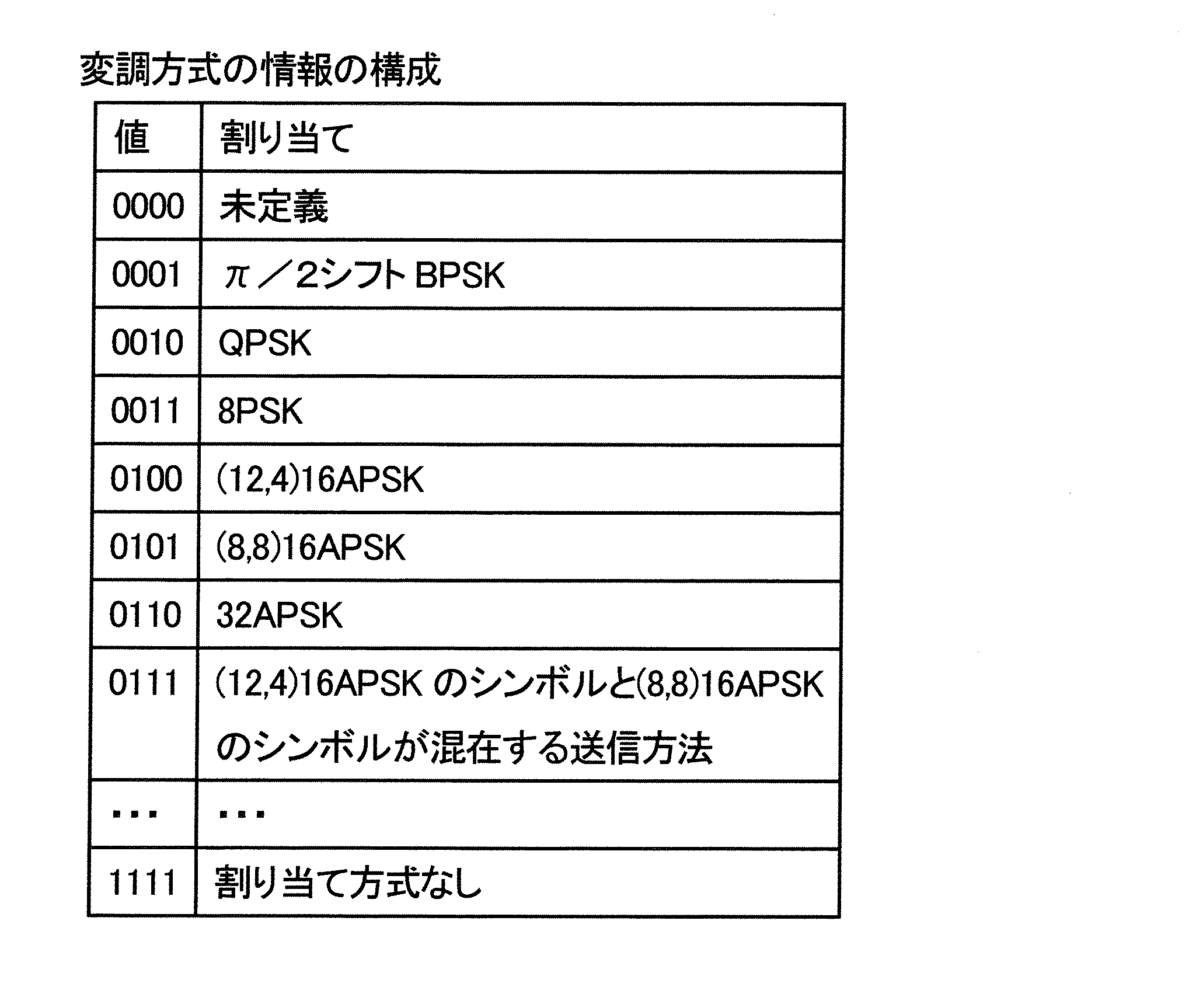
とを示している場合、(12,4)16APSKのリング比R(12,4)=2.97となる、ことを意味することになる。
・・・

・・・

・・・

図22(a)は、「ストリーム種別/相対ストリーム情報」の構成を示している。図22(a)では一例としてストリーム0からストリーム15のそれぞれのストリーム種別情報を伝送する構成をとっている。図22(a)の「相対ストリーム0のストリーム種別」とは、ストリーム0のストリーム種別情報であることを示している。
「相対ストリーム2のストリーム種別」とは、ストリーム2のストリーム種別情報であることを示している。
・・・
「相対ストリーム15のストリーム種別」とは、ストリーム15のストリーム種別情報であることを示している。
なお、各ストリームのストリーム種別情報は8ビットで構成されているものとする。(ただし、あくまでも例である。)
8ビットのストリーム種別情報が「00000000」は未定義である。
8ビットのストリーム種別情報が「00000001」のとき、ストリームがMPEG-2TS(Moving Picture Experts Group - 2 Transport Stream)であることを意味している。
8ビットのストリーム種別情報が「00000010」のとき、ストリームがTLV(Type Length Value)であることを意味している。
8ビットのストリーム種別情報が「00000011」のとき、ストリームが水平約4k(例えば3840)×垂直約2k(例えば2160)の画素数の映像(動画)であることを意味している。なお、映像符号化の情報を含んでいてもよい。
8ビットのストリーム種別情報が「00000100」のとき、ストリームが水平約8k(例えば7680)×垂直約4k(例えば4320)の画素数の映像(動画)であることを意味している。なお、映像符号化の情報を含んでいてもよい。
8ビットのストリーム種別情報が「00000101」のとき、ストリームが、水平約4k(例えば3840)×垂直約2k(例えば2160)の画素数の映像(動画)から水平約8k(例えば7680)×垂直約4k(例えば4320)の画素数の映像(動画)を生成するための差分情報であることを意味している。なお、映像符号化の情報を含んでいてもよい。また、この情報については、後で説明を付加する。
・・・
8ビットのストリーム種別情報が「11111111」は割り当て種別がない。
映像#Aのストリームが水平約4k(例えば3840)×垂直約2k(例えば2160)の画素数の映像(動画)で、送信装置は伝送するものとする。このとき、送信装置は8ビットのストリーム種別情報「00000011」を送信する。
また、受信装置は、ストリーム種別情報「00000011」を得、この情報から、ストリームが水平約4k(例えば3840)×垂直約2k(例えば2160)の画素数の映像(動画)であると判断し、加えて、ストリーム種別情報「00000101」を得、この情報から、ストリームが水平約4k(例えば3840)×垂直約2k(例えば2160)の画素数の映像(動画)から水平約8k(例えば7680)×垂直約4k(例えば4320)の画素数の映像(動画)を生成するための差分情報であると判断する。そして、受信装置は、この両者のストリームから、映像#Aの水平約8k(例えば7680)×垂直約4k(例えば4320)の画素数の映像(動画)を得ることができる。
次に、送信装置700が送信した無線信号を受信する受信装置の動作について、図19の受信装置の構成図を用いて説明する。
復調部1904は、ルートロールオフフィルタの処理等の処理を施し、フィルタ後のベースバンド信号を出力する。
デインターリーブ部1908は、対数尤度比を入力とし、蓄積し、送信装置が用いたインターリーブに対応するデインターリーブ(データの並び換え)を行い、デインターリーブ後の対数尤度比を出力する。

リング比に関する情報を伝送するシンボルにより、「00001」が伝送された場合、データシンボルは「(12,4)16APSKリング比4.10」のシンボルとなる。
リング比に関する情報を伝送するシンボルにより、「00010」が伝送された場合、データシンボルは「(12,4)16APSKリング比4.20」のシンボルとなる。
リング比に関する情報を伝送するシンボルにより、「00011」が伝送された場合、データシンボルは「(12,4)16APSKリング比4.30」のシンボルとなる。
リング比に関する情報を伝送するシンボルにより、「00101」が伝送された場合、データシンボルは「(8,8)16APSKリング比2.60」のシンボルとなる。
リング比に関する情報を伝送するシンボルにより、「00110」が伝送された場合、データシンボルは「(8,8)16APSKリング比2.70」のシンボルとなる。
リング比に関する情報を伝送するシンボルにより、「00111」が伝送された場合、データシンボルは「(8,8)16APSKリング比2.80」のシンボルとなる。
リング比に関する情報を伝送するシンボルにより、「01001」が伝送された場合、データシンボルは「(12,4)16APSKのシンボルと(8,8)16APSKのシンボルが混在する送信方法、(12,4)16APSKリング比4.00、(8,8)16APSKリング比2.60」のシンボルとなる。
リング比に関する情報を伝送するシンボルにより、「01010」が伝送された場合、データシンボルは「(12,4)16APSKのシンボルと(8,8)16APSKのシンボルが混在する送信方法、(12,4)16APSKリング比4.00、(8,8)16APSKリング比2.70」のシンボルとなる。
リング比に関する情報を伝送するシンボルにより、「01011」が伝送された場合、データシンボルは「(12,4)16APSKのシンボルと(8,8)16APSKのシンボルが混在する送信方法、(12,4)16APSKリング比4.00、(8,8)16APSKリング比2.80」のシンボルとなる。
リング比に関する情報を伝送するシンボルにより、「01101」が伝送された場合、データシンボルは「(12,4)16APSKのシンボルと(8,8)16APSKのシンボルが混在する送信方法、(12,4)16APSKリング比4.10、(8,8)16APSKリング比2.60」のシンボルとなる。
リング比に関する情報を伝送するシンボルにより、「01110」が伝送された場合、データシンボルは「(12,4)16APSKのシンボルと(8,8)16APSKのシンボルが混在する送信方法、(12,4)16APSKリング比4.10、(8,8)16APSKリング比2.70」のシンボルとなる。
リング比に関する情報を伝送するシンボルにより、「01111」が伝送された場合、データシンボルは「(12,4)16APSKのシンボルと(8,8)16APSKのシンボルが混在する送信方法、(12,4)16APSKリング比4.10、(8,8)16APSKリング比2.80」のシンボルとなる。
・・・・
また、変調方式を伝送するためのシンボルにおいて、リング比の情報を含んでいてもよい。例を以下に示す。

変調方式の情報を伝送するシンボルにより、「00001」が伝送された場合、データシンボルは「(12,4)16APSKリング比4.10」のシンボルとなる。
変調方式の情報を伝送するシンボルにより、「00010」が伝送された場合、データシンボルは「(12,4)16APSKリング比4.20」のシンボルとなる。
変調方式の情報を伝送するシンボルにより、「00011」が伝送された場合、データシンボルは「(12,4)16APSKリング比4.30」のシンボルとなる。
変調方式の情報を伝送するシンボルにより、「00101」が伝送された場合、データシンボルは「(8,8)16APSKリング比2.60」のシンボルとなる。
変調方式の情報を伝送するシンボルにより、「00110」が伝送された場合、データシンボルは「(8,8)16APSKリング比2.70」のシンボルとなる。
変調方式の情報を伝送するシンボルにより、「00111」が伝送された場合、データシンボルは「(8,8)16APSKリング比2.80」のシンボルとなる。
変調方式の情報を伝送するシンボルにより、「01001」が伝送された場合、データシンボルは「(12,4)16APSKのシンボルと(8,8)16APSKのシンボルが混在する送信方法、(12,4)16APSKリング比4.00、(8,8)16APSKリング比2.60」のシンボルとなる。
変調方式の情報を伝送するシンボルにより、「01010」が伝送された場合、データシンボルは「(12,4)16APSKのシンボルと(8,8)16APSKのシンボルが混在する送信方法、(12,4)16APSKリング比4.00、(8,8)16APSKリング比2.70」のシンボルとなる。
変調方式の情報を伝送するシンボルにより、「01011」が伝送された場合、データシンボルは「(12,4)16APSKのシンボルと(8,8)16APSKのシンボルが混在する送信方法、(12,4)16APSKリング比4.00、(8,8)16APSKリング比2.80」のシンボルとなる。
変調方式の情報を伝送するシンボルにより、「01101」が伝送された場合、データシンボルは「(12,4)16APSKのシンボルと(8,8)16APSKのシンボルが混在する送信方法、(12,4)16APSKリング比4.10、(8,8)16APSKリング比2.60」のシンボルとなる。
変調方式の情報を伝送するシンボルにより、「01110」が伝送された場合、データシンボルは「(12,4)16APSKのシンボルと(8,8)16APSKのシンボルが混在する送信方法、(12,4)16APSKリング比4.10、(8,8)16APSKリング比2.70」のシンボルとなる。
変調方式の情報を伝送するシンボルにより、「01111」が伝送された場合、データシンボルは「(12,4)16APSKのシンボルと(8,8)16APSKのシンボルが混在する送信方法、(12,4)16APSKリング比4.10、(8,8)16APSKリング比2.80」のシンボルとなる。
・・・・
変調方式の情報を伝送するシンボルにより、「11110」が伝送された場合、データシンボルは「QPSK」のシンボルとなる。
変調方式の情報を伝送するシンボルにより、「11111」が伝送された場合、データシンボルは「π/2シフトBPSK」のシンボルとなる。
本実施の形態では、データシンボルの生成の順番について説明する。
図18(a)において、「#1のシンボル群」、「#2のシンボル群」、「#3のシンボル群」、・・・、と並んでいるものとする。
このとき、「#1のシンボル群」、「#2のシンボル群」、「#3のシンボル群」、・・・の各シンボル群は、図18(a)に示すように、「同期シンボル群」「パイロットシンボル群」「TMCC情報シンボル群」「データシンボル群で構成されるスロット」で構成されているものとした。
ここでは、例えば、「#1のシンボル群」、「#2のシンボル群」、「#3のシンボル群」、・・・「#N-1のシンボル群」「#Nのシンボル群」のN個のシンボル群における「データシンボル群で構成されるスロット」を集めたデータシンボル群の構成方法について説明する。
・変調方式が(12,4)16APSKまたは(8,8)16APSKのいずれかであるシンボルが、3シンボル以上(または、4シンボル以上)連続するシンボル群において、(12,4)16APSKのシンボルが連続する部分が存在せず、かつ、(8,8)16APSKのシンボルが連続する部分が存在しない。
・図23を例とする、データシンボルが(12,4)16APSKのシンボル、(8,8)16APSKのシンボルのいずれかである場合、連続するデータシンボル群において、(8,8)16APSKのシンボルが3シンボル以上連続するところは存在しない。
のいずれかの送信方法によって生成されたシンボル群であることを意味する。
32APSKのデータシンボルが存在し、(8,8)16APSKのデータシンボルが存在しない場合、図20(a)に示すように、「32APSKのデータシンボル」のあとに「(8,8)16APSKのシンボルと(12,4)16APSKのシンボルが混在」のシンボルが存在する。
(8,8)16APSKのデータシンボルが存在する場合、図20(b)に示すように、「(8,8)16APSKのデータシンボル」のあとに「(8,8)16APSKのシンボルと(12,4)16APSKのシンボルが混在」のシンボルが存在する。
(12,4)16APSKのデータシンボルが存在する場合、図20(c)に示すように、「(8,8)16APSKのシンボルと(12,4)16APSKのシンボルが混在」のシンボルのあとに「(12,4)16APSKのデータシンボル」が存在する。
8PSKのデータシンボルが存在し、(12,4)16APSKのデータシンボルが存在しない場合、図20(d)に示すように、「(8,8)16APSKのシンボルと(12,4)16APSKのシンボルが混在」のシンボルのあとに「8PSKのデータシンボル」が存在する。
QPSKのデータシンボルが存在し、8PSKのデータシンボルが存在せず、また、(12,4)16APSKのデータシンボルが存在しない場合、図20(e)に示すように、「(8,8)16APSKのシンボルと(12,4)16APSKのシンボルが混在」のシンボルのあとに「QPSKのデータシンボル」が存在する。
π/2シフトBPSKのデータシンボルが存在し、QPSKのデータシンボルが存在せず、また、8PSKのデータシンボルが存在せず、また、(12,4)16APSKのデータシンボルが存在しない場合、図20(f)に示すように、「(8,8)16APSKのシンボルと(12,4)16APSKのシンボルが混在」のシンボルのあとに「π/2シフトBPSKのデータシンボル」が存在する。
誤り訂正符号の符号化率Xの「(8,8)16APSKのシンボルと(12,4)16APSKのシンボルが混在」のシンボルと誤り訂正符号の符号化率Yの「(8,8)16APSKのシンボルと(12,4)16APSKのシンボルが混在」のシンボルとが存在するものとする。そして、X>Yの関係が成立するものとする。
このとき、誤り訂正符号の符号化率Xの「(8,8)16APSKのシンボルと(12,4)16APSKのシンボルが混在」のシンボルのあとに誤り訂正符号の符号化率Yの「(8,8)16APSKのシンボルと(12,4)16APSKのシンボルが混在」のシンボルを配置する。
実施の形態1から実施の形態4では、送信フレームにおいて、(12,4)16APSKのシンボルと(8,8)16APSKのシンボルを切り替える方法、および、それに伴う、パイロットシンボルの構成方法、TMCCを含む制御情報の構成方法等について説明した。
したがって、本実施の形態では、(8,8)16APSKのシンボルのかわりに用いるNU-16QAMのシンボルの構成を中心に説明を行う。
図7のマッピング部708が行うNU-16QAMの信号点配置と各信号点へのビットの割り付け(ラベリング)について説明する。
信号点1-2[0001]・・・(R2,R1)
信号点1-3[0101]・・・(R2,-R1)
信号点1-4[0100]・・・(R2,-R2)
信号点2-1[0010]・・・(R1,R2)
信号点2-2[0011]・・・(R1,R1)
信号点2-3[0111]・・・(R1,-R1)
信号点2-4[0110]・・・(R1,-R2)
信号点3-1[1010]・・・(-R1,R2)
信号点3-2[1011]・・・(-R1,R1)
信号点3-3[1111]・・・(-R1,-R1)
信号点3-4[1110]・・・(-R1,-R2)
信号点4-1[1000]・・・(-R2,R2)
信号点4-2[1001]・・・(-R2,R1)
信号点4-3[1101]・・・(-R2,-R1)
信号点4-4[1100]・・・(-R2,-R2)
信号点1-1[0000]・・・(R2,R2)
と記載しているが、マッピング部708の入力となるデータにおいて、4つのビット[b3b2b1b0]=[0000]のとき、マッピング後のベースバンド信号の同相成分I、直交成分Qが、(I,Q)= (R2,R2)となることを意味している。もう一つの例で、
信号点4-4[1100]・・・(-R2,-R2)
と記載しているが、マッピング部708の入力となるデータにおいて、4つのビット[b3b2b1b0]=[1100]のとき、マッピング後のベースバンド信号の同相成分I、直交成分Qが、(I,Q)= (-R2,-R2)となることを意味している。
(12,4)16APSKのシンボルとNU-16QAMのシンボルにおける送信出力を同一にするために、次のような正規化係数を用いることがある。(12,4)16APSKのシンボルの正規化係数については、実施の形態1で説明したとおりである。NU-16QAMのシンボルの正規化係数は、次式で定義する。

信号点1-2[0001]・・・(In, Qn)=(aNU-16QAM×R2, aNU-16QAM×R1)
信号点1-3[0101]・・・(In, Qn)=(aNU-16QAM×R2,- aNU-16QAM×R1)
信号点1-4[0100]・・・(In, Qn)=(aNU-16QAM×R2,- aNU-16QAM×R2)
信号点2-1[0010]・・・(In, Qn)=(aNU-16QAM×R1, aNU-16QAM×R2)
信号点2-2[0011]・・・(In, Qn)=(aNU-16QAM×R1, aNU-16QAM×R1)
信号点2-3[0111]・・・(In, Qn)=(aNU-16QAM×R1,- aNU-16QAM×R1)
信号点2-4[0110]・・・(In, Qn)=(aNU-16QAM×R1,- aNU-16QAM×R2)
信号点3-1[1010]・・・(In, Qn)=(- aNU-16QAM×R1, aNU-16QAM×R2)
信号点3-2[1011]・・・(In, Qn)=(- aNU-16QAM×R1, aNU-16QAM×R1)
信号点3-3[1111]・・・(In, Qn)=(- aNU-16QAM×R1,- aNU-16QAM×R1)
信号点3-4[1110]・・・(In, Qn)=(- aNU-16QAM×R1,- aNU-16QAM×R2)
信号点4-1[1000]・・・(In, Qn)=(- aNU-16QAM×R2, aNU-16QAM×R2)
信号点4-2[1001]・・・(In, Qn)=(- aNU-16QAM×R2, aNU-16QAM×R1)
信号点4-3[1101]・・・(In, Qn)=(- aNU-16QAM×R2,- aNU-16QAM×R1)
信号点4-4[1100]・・・(In, Qn)=(- aNU-16QAM×R2,- aNU-16QAM×R2)
信号点1-1[0000]・・・(In, Qn)=(aNU-16QAM×R2, aNU-16QAM×R2)
と記載しているが、マッピング部708の入力となるデータにおいて、4つのビット[b3b2b1b0]=[0000]のとき、(In, Qn)=(aNU-16QAM×R2, aNU-16QAM×R2)となることを意味している。もう一つの例で、
信号点4-4[1100]・・・(In, Qn)=(- aNU-16QAM×R2,- aNU-16QAM×R2)
と記載しているが、マッピング部708の入力となるデータにおいて、4つのビット[b3b2b1b0]=[1100]のとき、(In, Qn)=(- aNU-16QAM×R2,- aNU-16QAM×R2)となることを意味している。
(12,4)16APSKのI-Q平面における信号点をあらわすのに用いたR1とR2より、(12,4)16APSKのリング比R(12,4)をR(12,4)=R2/R1とあらわすものとする。
このとき、「Ar<R(12,4)が成立すると、よりPAPRを小さくすることができる可能性が高くなる」という効果を得ることができる。
これは、ピーク電力を支配する可能性の高い変調方式は、NU-16QAMであるからである。このとき、NU-16QAMで発生するピーク電力は、Arが大きくなるにつれ、大きくなる可能性が高い。したがって、ピーク電力を大きくしないためには、Arを小さく設定するとよいことになり、一方、(12,4)16APSKのR(12,4)は、BER特性がよくなる値に設定すればよく自由度が高い。このため、Ar<R(12,4)という関係があるとよりPAPRを小さくすることができる可能性が高くなる。
ただし、Ar>R(12,4)であっても、NU-16QAMのPAPRより小さくできるという効果は得られる。したがって、BER特性を良くすることに着眼した場合に、Ar>R(12,4)がよい場合もある。
[NU-16QAMのラベリングについて]
ここでは、NU-16QAMのラベリングについて説明を行う。なお、ラベリングとは、入力となる4ビット[b3b2b1b0]と同相I―直交Q平面における信号点の配置の関係のことである。図26にNU-16QAMのラベリングの例を示したが、
以下の<条件5>かつ<条件6>を満たすラベリングであれば構わない。
伝送する4ビットが[ba3ba2ba1ba0]のとき、同相I―直交Q平面において信号点Aを与えるものとし、伝送する4ビットが[bb3bb2bb1bb0]のとき、同相I―直交Q平面において信号点Bを与えるものとする。このとき、
「ba3=bb3かつba2=bb2かつba1=bb1かつba0=bb0」のときラベリングの異なるビット数を0と定義する。
「ba3≠bb3かつba2=bb2かつba1=bb1かつba0=bb0」のときラベリングの異なるビット数を1と定義する。
「ba3=bb3かつba2≠bb2かつba1=bb1かつba0=bb0」のときラベリングの異なるビット数を1と定義する。
「ba3=bb3かつba2=bb2かつba1≠bb1かつba0=bb0」のときラベリングの異なるビット数を1と定義する。
「ba3=bb3かつba2=bb2かつba1=bb1かつba0≠bb0」のときラベリングの異なるビット数を1と定義する。
「ba3≠bb3かつba2≠bb2かつba1=bb1かつba0=bb0」のときラベリングの異なるビット数を2と定義する。
「ba3≠bb3かつba2=bb2かつba1≠bb1かつba0=bb0」のときラベリングの異なるビット数を2と定義する。
「ba3≠bb3かつba2=bb2かつba1=bb1かつba0≠bb0」のときラベリングの異なるビット数を2と定義する。
「ba3=bb3かつba2≠bb2かつba1≠bb1かつba0=bb0」のときラベリングの異なるビット数を2と定義する。
「ba3=bb3かつba2≠bb2かつba1=bb1かつba0≠bb0」のときラベリングの異なるビット数を2と定義する。
「ba3=bb3かつba2=bb2かつba1≠bb1かつba0≠bb0」のときラベリングの異なるビット数を2と定義する。
「ba3=bb3かつba2≠bb2かつba1≠bb1かつba0≠bb0」のときラベリングの異なるビット数を3と定義する。
「ba3≠bb3かつba2=bb2かつba1≠bb1かつba0≠bb0」のときラベリングの異なるビット数を3と定義する。
「ba3≠bb3かつba2≠bb2かつba1=bb1かつba0≠bb0」のときラベリングの異なるビット数を3と定義する。
「ba3≠bb3かつba2≠bb2かつba1≠bb1かつba0=bb0」のときラベリングの異なるビット数を3と定義する。
「ba3≠bb3かつba2≠bb2かつba1≠bb1かつba0≠bb0」のときラベリングの異なるビット数を4と定義する。
上述のNU-16QAMの説明における、信号点1-1、信号点1-2、信号点1-3、信号点1-4、信号点2-1、信号点2-2、信号点2-3、信号点2-4、信号点3-1、信号点3-2、信号点3-3、信号点3-4、信号点4-1、信号点4-2、信号点4-3、信号点4-4において、「信号点1-1、信号点1-2、信号点1-3、信号点1-4をグループ1」と定義する。同様に、「信号点2-1、信号点2-2、信号点2-3、信号点2-4をグループ2」、「信号点3-1、信号点3-2、信号点3-3、信号点3-4をグループ3」、「信号点4-1、信号点4-2、信号点4-3、信号点4-4をグループ4」と定義する。
<条件5>:
Xは1,2,3,4であり、これを満たす、すべてのXで以下が成立する。
信号点X-2と信号点X-3のラベリングの異なるビット数は1
信号点X-3と信号点X-4のラベリングの異なるビット数は1
uは1,2,3であり、vは1,2,3,4であり、これを満たす、すべてのu、ずべてのvで以下が成立する。
信号点u-vと信号点(u+1)-vのラベリングの異なるビット数は1
・変調方式が(12,4)16APSKまたはNU-16QAMのいずれかであるシンボルが、3シンボル以上(または、4シンボル以上)連続するシンボル群において、(12,4)16APSKのシンボルが連続する部分が存在せず、かつ、NU-16QAMのシンボルが連続する部分が存在しない。
・「周期Mのシンボル群」において、NU-16QAMのシンボル数は、(12,4)16APSKのシンボル数より1多い、つまり、(12,4)16APSKのシンボル数をNであり、NU-16QAMのシンボル数はN+1となる。(なお、Nは自然数となる。)そして、「周期Mのシンボル群」において、NU-16QAMのシンボルが2シンボル連続するところがない、または、NU-16QAMのシンボルが2シンボル連続するところが1箇所存在する。(よって、NU-16QAMのシンボルが3シンボル以上連続するところは存在しない。)
・データシンボルが(12,4)16APSKのシンボル、NU-16QAMのシンボルのいずれかである場合、連続するデータシンボル群において、NU-16QAMのシンボルが3シンボル以上連続するところは存在しない。
本実施の形態では、広帯域衛星デジタル放送に、実施の形態1から実施の形態5で説明した送信方法・送信装置、受信方法・受信装置を適用する場合の実施例を説明する。
本実施の形態では、実施の形態1、実施の形態2、実施の形態5等で説明した送信方法を用いた送信装置を受信側において、円滑に受信できるようにするためのTMCC情報としてシグナリングされる様々な情報の構成例について説明する。
広帯域衛星デジタル放送では、電力増幅器の歪みに関連して、TMCC情報において、「衛星出力バックオフ」の情報を送信装置が送信している。


実施の形態7では、実施の形態1から実施の形態4において、(8,8)16APSKのシンボルのかわりにNU-16QAMのシンボルを用いる場合について説明した。本実施の形態では、NU-16QAMの拡張として(4,8,4)16APSKを提案し(NU-16QAMは(4,8,4)16APSKの一つの例である。)、
実施の形態1から実施の形態4において、(8,8)16APSKのシンボルのかわりに(4,8,4)16APSKのシンボルを用いる場合について説明する。
実施の形態1から実施の形態4と同様な効果を得る方法としては、送信フレームにおいて、(12,4)16APSKのシンボルと(8,8)16APSKのシンボルを用いる方法に限ったものではなく、(12,4)16APSKのシンボルと(4,8,4)16APSKのシンボルを用いる方法でも、実施の形態1から実施の形態4と同様の効果を得ることができる。つまり、実施の形態1から実施の形態4において、(8,8)16APSKのシンボルのかわりに(4,8,4)16APSKのシンボルを用いればよいことになる(併用して用いる変調方式は(12,4)16APSKである。)。
図30に示すように、(4,8,4)16APSKマッピングの信号点は、同相I―直交Q平面において半径(振幅成分)の異なる3つの同心円に配置される。本明細書では、これらの同心円のうち、半径のR3の最も大きい円を「外円」、半径のR2の中間の大きさの円を「中円」、半径のR1の最も小さい円を「内円」と呼ぶ。なお、図30のようにR1、R2、R3を定義したとき(なお、R1は実数であり、R1>0とし、R2は実数であり、R2>0、R3は実数であり、R3>0、とする。また、R1<R2<R3とする。)
また、外円の円周上に4個の信号点、中円の円周上に8個の信号点、内円の円周上に4個の信号点が配置されている。(4,8,4)16APSKの(4,8,4)は、外円、中円、内円の順にそれぞれ4個、12個、4個の信号点があることを意味する。
信号点1-2[0001]・・・(R2cosλ,R2sinλ)
信号点1-3[0101]・・・(R2cos(-λ),R2sin(-λ))
信号点1-4[0100]・・・(R3cos(-π/4),R3sin(-π/4))
信号点2-1[0010]・・・(R2cos(-λ+π/2),R2sin(-λ+π/2))
信号点2-2[0011]・・・(R1cos(π/4),R1sin(π/4))
信号点2-3[0111]・・・(R1cos(-π/4),R1sin(-π/4))
信号点2-4[0110]・・・(R2cos(λ-π/2),R2sin(λ-π/2))
信号点3-1[1010]・・・(R2cos(λ+π/2),R2sin(λ+π/2))
信号点3-2[1011]・・・(R1cos(3π/4),R1sin(3π/4))
信号点3-3[1111]・・・(R1cos(-3π/4),R1sin(-3π/4))
信号点3-4[1110]・・・(R2cos(-λ-π/2),R2sin(-λ-π/2))
信号点4-1[1000]・・・(R3cos(3π/4),R3sin(3π/4))
信号点4-2[1001]・・・(R2cos(π-λ),R2sin(π-λ))
信号点4-3[1101]・・・(R2cos(-π+λ),R2sin(-π+λ))
信号点4-4[1100]・・・(R3cos(-3π/4),R3sin(-3π/4))
信号点1-1[0000]・・・(R3cos(π/4),R3sin(π/4))と記載しているが、マッピング部708の入力となるデータにおいて、4つのビット[b3b2b1b0]=[0000]のとき、マッピング後のベースバンド信号の同相成分I、直交成分Qが、(I,Q)= (R3cos(π/4),R3sin(π/4))となることを意味している。
信号点4-4[1100]・・・(R3cos(-3π/4),R3sin(-3π/4))と記載しているが、マッピング部708の入力となるデータにおいて、4つのビット[b3b2b1b0]=[1100]のとき、マッピング後のベースバンド信号の同相成分I、直交成分Qが、(I,Q)= (R3cos(-3π/4),R3sin(-3π/4))となることを意味している。
(12,4)16APSKのシンボルと(4,8,4)16APSKのシンボルにおける送信出力を同一にするために、次のような正規化係数を用いることがある。(12,4)16APSKのシンボルの正規化係数については、実施の形態1で説明したとおりである。(4,8,4)16APSKのシンボルの正規化係数は、次式で定義する。

信号点1-2[0001]・・・(In, Qn)=(a(4,8,4)×R2cosλ, a(4,8,4)×R2sinλ)
信号点1-3[0101]・・・(In, Qn)=(a(4,8,4)×R2cos(-λ), a(4,8,4)×R2sin(-λ))
信号点1-4[0100]・・・(In, Qn)=(a(4,8,4)×R3cos(-π/4), a(4,8,4)×R3sin(-π/4))
信号点2-1[0010]・・・(In, Qn)=(a(4,8,4)×R2cos(-λ+π/2), a(4,8,4)×R2sin(-λ+π/2))
信号点2-2[0011]・・・(In, Qn)=(a(4,8,4)×R1cos(π/4), a(4,8,4)×R1sin(π/4))
信号点2-3[0111]・・・(In, Qn)=(a(4,8,4)×R1cos(-π/4), a(4,8,4)×R1sin(-π/4))
信号点2-4[0110]・・・(In, Qn)=(a(4,8,4)×R2cos(λ-π/2), a(4,8,4)×R2sin(λ-π/2))
信号点3-1[1010]・・・(In, Qn)=(a(4,8,4)×R2cos(λ+π/2), a(4,8,4)×R2sin(λ+π/2))
信号点3-2[1011]・・・(In, Qn)=(a(4,8,4)×R1cos(3π/4), a(4,8,4)×R1sin(3π/4))
信号点3-3[1111]・・・(In, Qn)=(a(4,8,4)×R1cos(-3π/4), a(4,8,4)×R1sin(-3π/4))
信号点3-4[1110]・・・(In, Qn)=(a(4,8,4)×R2cos(-λ-π/2), a(4,8,4)×R2sin(-λ-π/2))
信号点4-1[1000]・・・(In, Qn)=(a(4,8,4)×R3cos(3π/4), a(4,8,4)×R3sin(3π/4))
信号点4-2[1001]・・・(In, Qn)=(a(4,8,4)×R2cos(π-λ), a(4,8,4)×R2sin(π-λ))
信号点4-3[1101]・・・(In, Qn)=(a(4,8,4)×R2cos(-π+λ), a(4,8,4)×R2sin(-π+λ))
信号点4-4[1100]・・・(In, Qn)=(a(4,8,4)×R3cos(-3π/4), a(4,8,4)×R3sin(-3π/4))
信号点1-1[0000]・・・(In, Qn)=(a(4,8,4)×R3cos(π/4), a(4,8,4)×R3sin(π/4))と記載しているが、マッピング部708の入力となるデータにおいて、4つのビット[b3b2b1b0]=[0000]のとき、(In, Qn)=(a(4,8,4)×R3cos(π/4), a(4,8,4)×R3sin(π/4))となることを意味している。もう一つの例で、
信号点4-4[1100]・・・(In, Qn)=(a(4,8,4)×R3cos(-3π/4), a(4,8,4)×R3sin(-3π/4))と記載しているが、マッピング部708の入力となるデータにおいて、4つのビット[b3b2b1b0]=[1100]のとき、(In, Qn)=(a(4,8,4)×R3cos(-3π/4), a(4,8,4)×R3sin(-3π/4))となることを意味している。
[(4,8,4)16APSKのラベリングについて]
ここでは、(4,8,4)16APSKのラベリングについて説明を行う。なお、ラベリングとは、入力となる4ビット[b3b2b1b0]と同相I―直交Q平面における信号点の配置の関係のことである。図30に(4,8,4)16APSKのラベリングの例を示したが、
以下の<条件7>かつ<条件8>を満たすラベリングであれば構わない。
伝送する4ビットが[ba3ba2ba1ba0]のとき、同相I―直交Q平面において信号点Aを与えるものとし、伝送する4ビットが[bb3bb2bb1bb0]のとき、同相I―直交Q平面において信号点Bを与えるものとする。このとき、
「ba3=bb3かつba2=bb2かつba1=bb1かつba0=bb0」のときラベリングの異なるビット数を0と定義する。
「ba3≠bb3かつba2=bb2かつba1=bb1かつba0=bb0」のときラベリングの異なるビット数を1と定義する。
「ba3=bb3かつba2≠bb2かつba1=bb1かつba0=bb0」のときラベリングの異なるビット数を1と定義する。
「ba3=bb3かつba2=bb2かつba1≠bb1かつba0=bb0」のときラベリングの異なるビット数を1と定義する。
「ba3=bb3かつba2=bb2かつba1=bb1かつba0≠bb0」のときラベリングの異なるビット数を1と定義する。
「ba3≠bb3かつba2≠bb2かつba1=bb1かつba0=bb0」のときラベリングの異なるビット数を2と定義する。
「ba3≠bb3かつba2=bb2かつba1≠bb1かつba0=bb0」のときラベリングの異なるビット数を2と定義する。
「ba3≠bb3かつba2=bb2かつba1=bb1かつba0≠bb0」のときラベリングの異なるビット数を2と定義する。
「ba3=bb3かつba2≠bb2かつba1≠bb1かつba0=bb0」のときラベリングの異なるビット数を2と定義する。
「ba3=bb3かつba2≠bb2かつba1=bb1かつba0≠bb0」のときラベリングの異なるビット数を2と定義する。
「ba3=bb3かつba2=bb2かつba1≠bb1かつba0≠bb0」のときラベリングの異なるビット数を2と定義する。
「ba3=bb3かつba2≠bb2かつba1≠bb1かつba0≠bb0」のときラベリングの異なるビット数を3と定義する。
「ba3≠bb3かつba2=bb2かつba1≠bb1かつba0≠bb0」のときラベリングの異なるビット数を3と定義する。
「ba3≠bb3かつba2≠bb2かつba1=bb1かつba0≠bb0」のときラベリングの異なるビット数を3と定義する。
「ba3≠bb3かつba2≠bb2かつba1≠bb1かつba0=bb0」のときラベリングの異なるビット数を3と定義する。
「ba3≠bb3かつba2≠bb2かつba1≠bb1かつba0≠bb0」のときラベリングの異なるビット数を4と定義する。
。同様に、「信号点2-1、信号点2-2、信号点2-3、信号点2-4をグループ2」、「信号点3-1、信号点3-2、信号点3-3、信号点3-4をグループ3」、「信号点4-1、信号点4-2、信号点4-3、信号点4-4をグループ4」と定義する。
<条件7>:
Xは1,2,3,4であり、これを満たす、すべてのXで以下が成立する。
信号点X-2と信号点X-3のラベリングの異なるビット数は1
信号点X-3と信号点X-4のラベリングの異なるビット数は1
uは1,2,3であり、vは1,2,3,4であり、これを満たす、すべてのu、ずべてのvで以下が成立する。
信号点u-vと信号点(u+1)-vのラベリングの異なるビット数は1
上述では、図30の同相I―直交Q平面における信号点配置とラベリングについて説明したが、同相I―直交Q平面における信号点配置とラベリングの方法はこれに限ったものではない。例えば、(4,8,4)16APSKの各信号点のIQ平面上の座標、ラベリングとして、以下のものを考える。
(cosθ×R3×cos(π/4)-sinθ×R3×sin(π/4), sinθ×R3×cos(π/4)+ cosθ×R3×sin(π/4))
信号点1-2[0001] のIQ平面上の座標:
(cosθ×R2×cosλ-sinθ×R2×sinλ, sinθ×R2×cosλ+ cosθ×R2×sinλ)
信号点1-3[0101] のIQ平面上の座標:
(cosθ×R2×cos(-λ)-sinθ×R2×sin(-λ), sinθ×R2×cos(-λ)+ cosθ×R2×sin(-λ))
信号点1-4[0100] のIQ平面上の座標:
(cosθ×R3×cos(-π/4)-sinθ×R3×sin(-π/4), sinθ×R3×cos(-π/4)+ cosθ×R3×sin(-π/4))
信号点2-1[0010] のIQ平面上の座標:
(cosθ×R2×cos(-λ+π/2)-sinθ×R2×sin(-λ+π/2), sinθ×R2×cos(-λ+π/2)+ cosθ×R2×sin(-λ+π/2))
信号点2-2[0011] のIQ平面上の座標:
(cosθ×R1×cos(π/4)-sinθ×R1×sin(π/4), sinθ×R1×cos(π/4)+ cosθ×R1×sin(π/4))
信号点2-3[0111] のIQ平面上の座標:
(cosθ×R1×cos(-π/4)-sinθ×R1×sin(-π/4), sinθ×R1×cos(-π/4)+ cosθ×R1×sin(-π/4))
信号点2-4[0110] のIQ平面上の座標:
(cosθ×R2×cos(λ-π/2)-sinθ×R2×sin(λ-π/2), sinθ×R2×cos(λ-π/2)+ cosθ×R2×sin(λ-π/2))
信号点3-1[1010] のIQ平面上の座標:
(cosθ×R2×cos(λ+π/2)-sinθ×R2×sin(λ+π/2), sinθ×R2×cos(λ+π/2)+ cosθ×R2×sin(λ+π/2))
信号点3-2[1011] のIQ平面上の座標:
(cosθ×R1×cos(3π/4)-sinθ×R1×sin(3π/4), sinθ×R1×cos(3π/4)+ cosθ×R1×sin(3π/4))
信号点3-3[1111] のIQ平面上の座標:
(cosθ×R1×cos(-3π/4)-sinθ×R1×sin(-3π/4), sinθ×R1×cos(-3π/4)+ cosθ×R1×sin(-3π/4))
信号点3-4[1110] のIQ平面上の座標:
(cosθ×R2×cos(-λ-π/2)-sinθ×R2×sin(-λ-π/2), sinθ×R2×cos(-λ-π/2)+ cosθ×R2×sin(-λ-π/2))
信号点4-1[1000] のIQ平面上の座標:
(cosθ×R3×cos(3π/4)-sinθ×R3×sin(3π/4), sinθ×R3×cos(3π/4)+ cosθ×R3×sin(3π/4))
信号点4-2[1001] のIQ平面上の座標:
(cosθ×R2×cos(π-λ)-sinθ×R2×sin(π-λ), sinθ×R2×cos(π-λ)+ cosθ×R2×sin(π-λ))
信号点4-3[1101] のIQ平面上の座標:
(cosθ×R2×cos(-π+λ)-sinθ×R2×sin(-π+λ), sinθ×R2×cos(-π+λ)+ cosθ×R2×sin(-π+λ))
信号点4-4[1100] のIQ平面上の座標:
(cosθ×R3×cos(-3π/4)-sinθ×R3×sin(-3π/4), sinθ×R3×cos(-3π/4)+ cosθ×R3×sin(-3π/4))
(In, Qn)=(a(4,8,4)×cosθ×R3×cos(π/4)- a(4,8,4)×sinθ×R3×sin(π/4), a(4,8,4)×sinθ×R3×cos(π/4)+ a(4,8,4)×cosθ×R3×sin(π/4))
信号点1-2[0001] のIQ平面上の座標:
(In, Qn)=(a(4,8,4)×cosθ×R2×cosλ- a(4,8,4)×sinθ×R2×sinλ, a(4,8,4)×sinθ×R2×cosλ+ a(4,8,4)×cosθ×R2×sinλ)
信号点1-3[0101] のIQ平面上の座標:
(In, Qn)=(a(4,8,4)×cosθ×R2×cos(-λ)- a(4,8,4)×sinθ×R2×sin(-λ), a(4,8,4)×sinθ×R2×cos(-λ)+ a(4,8,4)×cosθ×R2×sin(-λ))
信号点1-4[0100] のIQ平面上の座標:
(In, Qn)=(a(4,8,4)×cosθ×R3×cos(-π/4)- a(4,8,4)×sinθ×R3×sin(-π/4), a(4,8,4)×sinθ×R3×cos(-π/4)+ a(4,8,4)×cosθ×R3×sin(-π/4))
信号点2-1[0010] のIQ平面上の座標:
(In, Qn)=(a(4,8,4)×cosθ×R2×cos(-λ+π/2)- a(4,8,4)×sinθ×R2×sin(-λ+π/2), a(4,8,4)×sinθ×R2×cos(-λ+π/2)+ a(4,8,4)×cosθ×R2×sin(-λ+π/2))
信号点2-2[0011] のIQ平面上の座標:
(In, Qn)=(a(4,8,4)×cosθ×R1×cos(π/4)- a(4,8,4)×sinθ×R1×sin(π/4), a(4,8,4)×sinθ×R1×cos(π/4)+ a(4,8,4)×cosθ×R1×sin(π/4))
信号点2-3[0111] のIQ平面上の座標:
(In, Qn)=(a(4,8,4)×cosθ×R1×cos(-π/4)- a(4,8,4)×sinθ×R1×sin(-π/4), a(4,8,4)×sinθ×R1×cos(-π/4)+ a(4,8,4)×cosθ×R1×sin(-π/4))
信号点2-4[0110] のIQ平面上の座標:
(In, Qn)=(a(4,8,4)×cosθ×R2×cos(λ-π/2)- a(4,8,4)×sinθ×R2×sin(λ-π/2), a(4,8,4)×sinθ×R2×cos(λ-π/2)+ a(4,8,4)×cosθ×R2×sin(λ-π/2))
信号点3-1[1010] のIQ平面上の座標:
(In, Qn)=(a(4,8,4)×cosθ×R2×cos(λ+π/2)- a(4,8,4)×sinθ×R2×sin(λ+π/2), a(4,8,4)×sinθ×R2×cos(λ+π/2)+ a(4,8,4)× cosθ×R2×sin(λ+π/2))
信号点3-2[1011] のIQ平面上の座標:
(In, Qn)=(a(4,8,4)×cosθ×R1×cos(3π/4)- a(4,8,4)×sinθ×R1×sin(3π/4), a(4,8,4)×sinθ×R1×cos(3π/4)+ a(4,8,4)×cosθ×R1×sin(3π/4))
信号点3-3[1111] のIQ平面上の座標:
(In, Qn)=(a(4,8,4)×cosθ×R1×cos(-3π/4)- a(4,8,4)×sinθ×R1×sin(-3π/4), a(4,8,4)×sinθ×R1×cos(-3π/4)+ a(4,8,4)×cosθ×R1×sin(-3π/4))
信号点3-4[1110] のIQ平面上の座標:
(In, Qn)=(a(4,8,4)×cosθ×R2×cos(-λ-π/2)- a(4,8,4)×sinθ×R2×sin(-λ-π/2), a(4,8,4)×sinθ×R2×cos(-λ-π/2)+ a(4,8,4)×cosθ×R2×sin(-λ-π/2))
信号点4-1[1000] のIQ平面上の座標:
(In, Qn)=(a(4,8,4)×cosθ×R3×cos(3π/4)- a(4,8,4)×sinθ×R3×sin(3π/4), a(4,8,4)×sinθ×R3×cos(3π/4)+ a(4,8,4)×cosθ×R3×sin(3π/4))
信号点4-2[1001] のIQ平面上の座標:
(In, Qn)=(a(4,8,4)×cosθ×R2×cos(π-λ)- a(4,8,4)×sinθ×R2×sin(π-λ), a(4,8,4)×sinθ×R2×cos(π-λ)+ a(4,8,4)×cosθ×R2×sin(π-λ))
信号点4-3[1101] のIQ平面上の座標:
(In, Qn)=(a(4,8,4)×cosθ×R2×cos(-π+λ)- a(4,8,4)×sinθ×R2×sin(-π+λ), a(4,8,4)×sinθ×R2×cos(-π+λ)+ a(4,8,4)×cosθ×R2×sin(-π+λ))
信号点4-4[1100] のIQ平面上の座標:
(In, Qn)=(a(4,8,4)×cosθ×R3×cos(-3π/4)- a(4,8,4)×sinθ×R3×sin(-3π/4), a(4,8,4)×sinθ×R3×cos(-3π/4)+ a(4,8,4)×cosθ×R3×sin(-3π/4))
・変調方式が(12,4)16APSKまたは(4,8,4)16APSKのいずれかであるシンボルが、3シンボル以上(または、4シンボル以上)連続するシンボル群において、(12,4)16APSKのシンボルが連続する部分が存在せず、かつ、(4,8,4)16APSKのシンボルが連続する部分が存在しない。
・「周期Mのシンボル群」において、(4,8,4)16APSKのシンボル数は、(12,4)16APSKのシンボル数より1多い、つまり、(12,4)16APSKのシンボル数をNであり、(4,8,4)16APSKのシンボル数はN+1となる。(なお、Nは自然数となる。)そして、「周期Mのシンボル群」において、(4,8,4)16APSKのシンボルが2シンボル連続するところがない、または、(4,8,4)16APSKのシンボルが2シンボル連続するところが1箇所存在する。(よって、(4,8,4)16APSKのシンボルが3シンボル以上連続するところは存在しない。)
・データシンボルが(12,4)16APSKのシンボル、(4,8,4)16APSKのシンボルのいずれかである場合、連続するデータシンボル群において、(4,8,4)16APSKのシンボルが3シンボル以上連続するところは存在しない。
実施の形態8では、実施の形態1から実施の形態4において、(8,8)16APSKのシンボルのかわりに(4,8,4)16APSKのシンボルを用いる場合について説明した。本実施の形態では、実施の形態9で説明した(4,8,4)16APSK において、データの受信品質を向上させるための信号点配置に関する条件を説明する。
図30では、λ<π/8ラジアンとして、(4,8,4)16APSKの16個の信号点を描いている。
<条件9>
λ<π/8ラジアンであるとよい(高いデータの受信品質を得るための一つの条件となる)。
R1sin(π/4)<R2sinλ
「内円」に存在する4個の信号点のうち、最小のユークリッド距離をαとする。(信号点2-2と信号点2-3のユークリッド距離、信号点2-3と信号点3-3のユークリッド距離、信号点3-3と信号点3-2のユークリッド距離、信号点3-2と信号点2-2の距離はαとなる。)
「中円」の8個の信号点のうち、信号点1-2と信号点1-3のユークリッド距離をβとする。なお、信号点2-1と信号点3-1のユークリッド距離、信号点4-2と信号点4-3のユークリッド距離、信号点3-4と信号点2-4のユークリッド距離もβとなる。
R1sin(π/4)≠R2sinλ
信号点1-1の座標は、(R3cos(π/4),R3sin(π/4))であり、信号点1-2の座標は(R2cosλ,R2sinλ)である。そして、以下の条件を与える。
R2cosλ≠R3cos(π/4)
[1] 実施の形態8で述べた同相I―直交Qの(4,8,4)16APSKの信号点の配置(信号点の座標)に対し、<条件10>を満たす。(ただし、R1<R2<R3)
[2] 実施の形態8で述べた同相I―直交Qの(4,8,4)16APSKの信号点の配置(信号点の座標)に対し、<条件11>を満たす。(ただし、R1<R2<R3)
[3] 実施の形態8で述べた同相I―直交Qの(4,8,4)16APSKの信号点の配置(信号点の座標)に対し、<条件12>を満たす。(ただし、R1<R2<R3)
[4] 実施の形態8で述べた同相I―直交Qの(4,8,4)16APSKの信号点の配置(信号点の座標)に対し、<条件9>および<条件10>を満たす。(ただし、R1<R2<R3)
[5]実施の形態8で述べた同相I―直交Qの(4,8,4)16APSKの信号点の配置(信号点の
座標)に対し、<条件9>および<条件11>を満たす。(ただし、R1<R2<R3)
[6] 実施の形態8で述べた同相I―直交Qの(4,8,4)16APSKの信号点の配置(信号点の座標)に対し、<条件9>および<条件12>を満たす。(ただし、R1<R2<R3)
[7] 実施の形態8で述べた同相I―直交Qの(4,8,4)16APSKの信号点の配置(信号点の座標)に対し、<条件10>を満たし、λ=π/12ラジアンとする。(ただし、R1<R2<R3)
[8]実施の形態8で述べた同相I―直交Qの(4,8,4)16APSKの信号点の配置(信号点の座標)に対し、<条件11>を満たし、λ=π/12ラジアンとする。(ただし、R1<R2<R3)
[9] 実施の形態8で述べた同相I―直交Qの(4,8,4)16APSKの信号点の配置(信号点の座標)に対し、<条件12>を満たし、λ=π/12ラジアンとする。(ただし、R1<R2<R3)
[10] 実施の形態8で述べた同相I―直交Qの(4,8,4)16APSKの信号点の配置(信号点の座標)に対し、<条件10>を満たし、かつ、<条件7>および<条件8>を満たす。(ただし、R1<R2<R3)
[11] 実施の形態8で述べた同相I―直交Qの(4,8,4)16APSKの信号点の配置(信号点の座標)に対し、<条件11>を満たし、かつ、<条件7>および<条件8>を満たす。(ただし、R1<R2<R3)
[12] 実施の形態8で述べた同相I―直交Qの(4,8,4)16APSKの信号点の配置(信号点の座標)に対し、<条件12>を満たし、かつ、<条件7>および<条件8>を満たす。(ただし、R1<R2<R3)
[13] 実施の形態8で述べた同相I―直交Qの(4,8,4)16APSKの信号点の配置(信号点の座標)に対し、<条件9>および<条件10>を満たし、かつ、<条件7>および<条件8>を満たす。(ただし、R1<R2<R3)
[14]実施の形態8で述べた同相I―直交Qの(4,8,4)16APSKの信号点の配置(信号点の座標)に対し、<条件9>および<条件11>を満たし、かつ、<条件7>および<条件8>を満たす。(ただし、R1<R2<R3)
[15] 実施の形態8で述べた同相I―直交Qの(4,8,4)16APSKの信号点の配置(信号点の座標)に対し、<条件9>および<条件12>を満たし、かつ、<条件7>および<条件8>を満たす。(ただし、R1<R2<R3)
[16] 実施の形態8で述べた同相I―直交Qの(4,8,4)16APSKの信号点の配置(信号点の座標)に対し、<条件10>を満たし、λ=π/12ラジアンとし、かつ、<条件7>および<条件8>を満たす。(ただし、R1<R2<R3)
[17]実施の形態8で述べた同相I―直交Qの(4,8,4)16APSKの信号点の配置(信号点の座標)に対し、<条件11>を満たし、λ=π/12ラジアンとし、かつ、<条件7>および<条件8>を満たす。(ただし、R1<R2<R3)
[18] 実施の形態8で述べた同相I―直交Qの(4,8,4)16APSKの信号点の配置(信号点の座標)に対し、<条件12>を満たし、λ=π/12ラジアンとし、かつ、<条件7>および<条件8>を満たす。(ただし、R1<R2<R3)
実施の形態1から実施の形態4では、送信フレームにおいて、(12,4)16APSKのシンボルと(8,8)16APSKのシンボルを切り替える方法、および、それに伴う、パイロットシンボルの構成方法、TMCCを含む制御情報の構成方法等について説明した。そして、実施の形態7では、実施の形態1から実施の形態4に対し、(8,8)16APSKの代わりにNU-16QAMを用いる方法、そして、実施の形態8では、実施の形態1から実施の形態4に対し、(8,8)16APSKの代わりに(4,8,4)16APSKを用いる方法について説明した。
本実施の形態では、この点、つまり、データシンボルの変調方式として、(4,8,4)16APSKを指定することができる送信方法について説明する。
例えば、シングルキャリア伝送方式を用いている場合、時間軸方向に連続することになる。(図33参照)また、OFDM(Orthogonal Frequency Division Multiplexing)方式を例とするマルチキャリアの伝送方式を用いている場合、2シンボル以上連続する(4,8,4)16APSKのシンボルは、、時間軸方向で連続していてもよいし(図33参照)、周波数軸方向で連続していてもよい(図34参照)。
[1] 実施の形態8で述べた同相I―直交Qの(4,8,4)16APSKの信号点の配置(信号点の座標)に対し、<条件10>を満たす。(ただし、R1<R2<R3)
[2] 実施の形態8で述べた同相I―直交Qの(4,8,4)16APSKの信号点の配置(信号点の座標)に対し、<条件11>を満たす。(ただし、R1<R2<R3)
[3] 実施の形態8で述べた同相I―直交Qの(4,8,4)16APSKの信号点の配置(信号点の座標)に対し、<条件12>を満たす。(ただし、R1<R2<R3)
[4] 実施の形態8で述べた同相I―直交Qの(4,8,4)16APSKの信号点の配置(信号点の座標)に対し、<条件9>および<条件10>を満たす。(ただし、R1<R2<R3)
[5]実施の形態8で述べた同相I―直交Qの(4,8,4)16APSKの信号点の配置(信号点の座標)に対し、<条件9>および<条件11>を満たす。(ただし、R1<R2<R3)
[6] 実施の形態8で述べた同相I―直交Qの(4,8,4)16APSKの信号点の配置(信号点の座標)に対し、<条件9>および<条件12>を満たす。(ただし、R1<R2<R3)
[7] 実施の形態8で述べた同相I―直交Qの(4,8,4)16APSKの信号点の配置(信号点の座標)に対し、<条件10>を満たし、λ=π/12ラジアンとする。(ただし、R1<R2<R3)
[8]実施の形態8で述べた同相I―直交Qの(4,8,4)16APSKの信号点の配置(信号点の座標)に対し、<条件11>を満たし、λ=π/12ラジアンとする。(ただし、R1<R2<R3)
[9] 実施の形態8で述べた同相I―直交Qの(4,8,4)16APSKの信号点の配置(信号点の座標)に対し、<条件12>を満たし、λ=π/12ラジアンとする。(ただし、R1<R2<R3)
[10] 実施の形態8で述べた同相I―直交Qの(4,8,4)16APSKの信号点の配置(信号点の座標)に対し、<条件10>を満たし、かつ、<条件7>および<条件8>を満たす。(ただし、R1<R2<R3)
[11] 実施の形態8で述べた同相I―直交Qの(4,8,4)16APSKの信号点の配置(信号点の座標)に対し、<条件11>を満たし、かつ、<条件7>および<条件8>を満たす。(ただし、R1<R2<R3)
[12] 実施の形態8で述べた同相I―直交Qの(4,8,4)16APSKの信号点の配置(信号点の座標)に対し、<条件12>を満たし、かつ、<条件7>および<条件8>を満たす。(ただし、R1<R2<R3)
[13] 実施の形態8で述べた同相I―直交Qの(4,8,4)16APSKの信号点の配置(信号点の座標)に対し、<条件9>および<条件10>を満たし、かつ、<条件7>および<条件8>を満たす。(ただし、R1<R2<R3)
[14]実施の形態8で述べた同相I―直交Qの(4,8,4)16APSKの信号点の配置(信号点の座標)に対し、<条件9>および<条件11>を満たし、かつ、<条件7>および<条件8>を満たす。(ただし、R1<R2<R3)
[15] 実施の形態8で述べた同相I―直交Qの(4,8,4)16APSKの信号点の配置(信号点の座標)に対し、<条件9>および<条件12>を満たし、かつ、<条件7>および<条件8>を満たす。(ただし、R1<R2<R3)
[16] 実施の形態8で述べた同相I―直交Qの(4,8,4)16APSKの信号点の配置(信号点の座標)に対し、<条件10>を満たし、λ=π/12ラジアンとし、かつ、<条件7>および<条件8>を満たす。(ただし、R1<R2<R3)
[17]実施の形態8で述べた同相I―直交Qの(4,8,4)16APSKの信号点の配置(信号点の座標)に対し、<条件11>を満たし、λ=π/12ラジアンとし、かつ、<条件7>および<条件8>を満たす。(ただし、R1<R2<R3)
[18] 実施の形態8で述べた同相I―直交Qの(4,8,4)16APSKの信号点の配置(信号点の座標)に対し、<条件12>を満たし、λ=π/12ラジアンとし、かつ、<条件7>および<条件8>を満たす。(ただし、R1<R2<R3)
[19] 実施の形態8で述べた同相I―直交Qの(4,8,4)16APSKの信号点の配置(信号点の座標)に対し、<条件9>および<条件10>を満たす。(ただし、R1<R2<R3)
[20] 実施の形態8で述べた同相I―直交Qの(4,8,4)16APSKの信号点の配置(信号点の座標)に対し、<条件9>および<条件10>を満たし、かつ、<条件7>および<条件8>を満たす。(ただし、R1<R2<R3)
<パイロットシンボルの例>
本実施の形態では、上記の実施の形態10で説明した送信方式(データシンボルの変調方式が(4,8,4)16APSK)におけるパイロットシンボルの構成例について説明する。
送信装置の電力増幅器の非線形性から、変調信号は、符号間干渉が発生する。受信装置では、この符号間干渉を低減させることで、高いデータの受信品質を得ることができる。
「(4,8,4)16APSKのシンボルが2シンボル以上連続している」
が成立する場合、(4,8,4)16APSKが取り得る同相I―直交Q平面のすべての信号点に相当するベースバンド信号(つまり、伝送する4ビット[b3b2b1b0]が[0000]から[1111]の16個の信号点に相当するベースバンド信号)、を発生させ、パイロットシンボルとして送信する方法を提案する。これにより、受信装置は、(4,8,4)16APSKが取り得る同相I―直交Q平面のすべての信号点における符号間干渉を推定することができるので、高いデータの受信品質を得ることができる可能性が高い。
(4,8,4)16APSK 16APSKの[b3b2b1b0]=[0000]に対応する信号点(ベースバンド信号)のシンボル、
(4,8,4)16APSK 16APSKの[b3b2b1b0]=[0001]に対応する信号点(ベースバンド信号)のシンボル、
(4,8,4)16APSK 16APSKの[b3b2b1b0]=[0010]に対応する信号点(ベースバンド信号)のシンボル、
(4,8,4)16APSK 16APSKの[b3b2b1b0]=[0011]に対応する信号点(ベースバンド信号)のシンボル、
(4,8,4)16APSK 16APSKの[b3b2b1b0]=[0100]に対応する信号点(ベースバンド信号)のシンボル、
(4,8,4)16APSK 16APSKの[b3b2b1b0]=[0101]に対応する信号点(ベースバンド信号)のシンボル、
(4,8,4)16APSK 16APSKの[b3b2b1b0]=[0110]に対応する信号点(ベースバンド信号)のシンボル、
(4,8,4)16APSK 16APSKの[b3b2b1b0]=[0111]に対応する信号点(ベースバンド信号)のシンボル、
(4,8,4)16APSK 16APSKの[b3b2b1b0]=[1000]に対応する信号点(ベースバンド信号)のシンボル、
(4,8,4)16APSK 16APSKの[b3b2b1b0]=[1001]に対応する信号点(ベースバンド信号)のシンボル、
(4,8,4)16APSK 16APSKの[b3b2b1b0]=[1010]に対応する信号点(ベースバンド信号)のシンボル、
(4,8,4)16APSK 16APSKの[b3b2b1b0]=[1011]に対応する信号点(ベースバンド信号)のシンボル、
(4,8,4)16APSK 16APSKの[b3b2b1b0]=[1100]に対応する信号点(ベースバンド信号)のシンボル、
(4,8,4)16APSK 16APSKの[b3b2b1b0]=[1101]に対応する信号点(ベースバンド信号)のシンボル、
(4,8,4)16APSK 16APSKの[b3b2b1b0]=[1110]に対応する信号点(ベースバンド信号)のシンボル、
(4,8,4)16APSK 16APSKの[b3b2b1b0]=[1111]に対応する信号点(ベースバンド信号)のシンボル、
をパイロットシンボル(リファレンスシンボル)として送信する。
<1>((4,8,4)16APSKが取り得る同相I―直交Q平面のすべての信号点に相当するシンボル、つまり、
(4,8,4)16APSK 16APSKの[b3b2b1b0]=[0000]に対応する信号点(ベースバンド信号)のシンボル、
(4,8,4)16APSK 16APSKの[b3b2b1b0]=[0001]に対応する信号点(ベースバンド信号)のシンボル、
(4,8,4)16APSK 16APSKの[b3b2b1b0]=[0010]に対応する信号点(ベースバンド信号)のシンボル、
(4,8,4)16APSK 16APSKの[b3b2b1b0]=[0011]に対応する信号点(ベースバンド信号)のシンボル、
(4,8,4)16APSK 16APSKの[b3b2b1b0]=[0100]に対応する信号点(ベースバンド信号)のシンボル、
(4,8,4)16APSK 16APSKの[b3b2b1b0]=[0101]に対応する信号点(ベースバンド信号)のシンボル、
(4,8,4)16APSK 16APSKの[b3b2b1b0]=[0110]に対応する信号点(ベースバンド信号)のシンボル、
(4,8,4)16APSK 16APSKの[b3b2b1b0]=[0111]に対応する信号点(ベースバンド信号)のシンボル、
(4,8,4)16APSK 16APSKの[b3b2b1b0]=[1000]に対応する信号点(ベースバンド信号)のシンボル、
(4,8,4)16APSK 16APSKの[b3b2b1b0]=[1001]に対応する信号点(ベースバンド信号)のシンボル、
(4,8,4)16APSK 16APSKの[b3b2b1b0]=[1010]に対応する信号点(ベースバンド信号)のシンボル、
(4,8,4)16APSK 16APSKの[b3b2b1b0]=[1011]に対応する信号点(ベースバンド信号)のシンボル、
(4,8,4)16APSK 16APSKの[b3b2b1b0]=[1100]に対応する信号点(ベースバンド信号)のシンボル、
(4,8,4)16APSK 16APSKの[b3b2b1b0]=[1101]に対応する信号点(ベースバンド信号)のシンボル、
(4,8,4)16APSK 16APSKの[b3b2b1b0]=[1110]に対応する信号点(ベースバンド信号)のシンボル、
(4,8,4)16APSK 16APSKの[b3b2b1b0]=[1111]に対応する信号点(ベースバンド信号)のシンボル、
を送信することであり、送信する順番は、どのような順番であってもよい。
(4,8,4)16APSK 16APSKの[b3b2b1b0]=[0000]に対応する信号点(ベースバンド信号)のシンボル、
(4,8,4)16APSK 16APSKの[b3b2b1b0]=[0001]に対応する信号点(ベースバンド信号)のシンボル、
(4,8,4)16APSK 16APSKの[b3b2b1b0]=[0010]に対応する信号点(ベースバンド信号)のシンボル、
(4,8,4)16APSK 16APSKの[b3b2b1b0]=[0011]に対応する信号点(ベースバンド信号)のシンボル、
(4,8,4)16APSK 16APSKの[b3b2b1b0]=[0100]に対応する信号点(ベースバンド信号)のシンボル、
(4,8,4)16APSK 16APSKの[b3b2b1b0]=[0101]に対応する信号点(ベースバンド信号)のシンボル、
(4,8,4)16APSK 16APSKの[b3b2b1b0]=[0110]に対応する信号点(ベースバンド信号)のシンボル、
(4,8,4)16APSK 16APSKの[b3b2b1b0]=[0111]に対応する信号点(ベースバンド信号)のシンボル、
(4,8,4)16APSK 16APSKの[b3b2b1b0]=[1000]に対応する信号点(ベースバンド信号)のシンボル、
(4,8,4)16APSK 16APSKの[b3b2b1b0]=[1001]に対応する信号点(ベースバンド信号)のシンボル、
(4,8,4)16APSK 16APSKの[b3b2b1b0]=[1010]に対応する信号点(ベースバンド信号)のシンボル、
(4,8,4)16APSK 16APSKの[b3b2b1b0]=[1011]に対応する信号点(ベースバンド信号)のシンボル、
(4,8,4)16APSK 16APSKの[b3b2b1b0]=[1100]に対応する信号点(ベースバンド信号)のシンボル、
(4,8,4)16APSK 16APSKの[b3b2b1b0]=[1101]に対応する信号点(ベースバンド信号)のシンボル、
(4,8,4)16APSK 16APSKの[b3b2b1b0]=[1110]に対応する信号点(ベースバンド信号)のシンボル、
(4,8,4)16APSK 16APSKの[b3b2b1b0]=[1111]に対応する信号点(ベースバンド信号)のシンボル、
の各シンボルの出現回数を等しくすることができるという利点がある。
<シグナリング>
本実施の形態では、上記の実施の形態10で説明した送信方式を用いた送信信号を、受信装置側において円滑に受信できるようにするために、TMCC情報としてシグナリングされる様々な情報の構成例について説明する。
図18は、高度広帯域衛星デジタル放送における送信信号のフレーム構成のイメージ図を示している。(ただし、高度広帯域衛星デジタル放送のフレーム構成を正確に図示したものではない。)なお、詳細については実施の形態3で説明したので、ここでは説明を省略する。
・・・
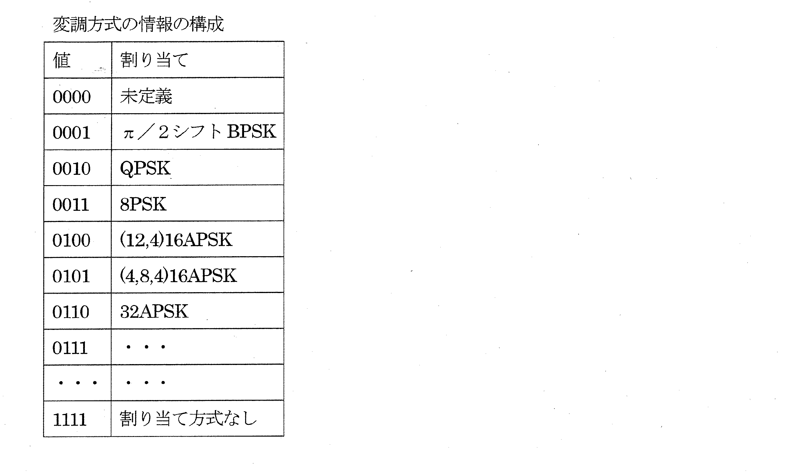
・・・

・・・

次に、送信装置700が送信した無線信号を受信する受信装置の動作について、図19の受信装置の構成図を用いて説明する。
復調部1904は、ルートロールオフフィルタの処理等の処理を施し、フィルタ後のベースバンド信号を出力する。
同期・チャネル推定部1914は、フィルタ後のベースバンド信号を入力とし、送信装置が送信した、例えば、「同期シンボル群」「パイロットシンボル群」を用いて、時間同期、周波数同期、チャネル推定を行い、推定信号を出力する。
制御情報推定部1916は、フィルタ後のベースバンド信号を入力とし、「TMCC情報シンボル群」のような制御情報を含むシンボルを抽出し、復調・復号を行い、制御信号を出力する。
デインターリーブ部1908は、対数尤度比を入力とし、蓄積し、送信装置が用いたインターリーブに対応するデインターリーブ(データの並び換え)を行い、デインターリーブ後の対数尤度比を出力する。
インターリーブ部1910は、復号後の各ビットの対数尤度比をインターリーブし(並び替えを行い)、インターリーブ後の対数尤度比を出力する。
である場合はリング比、半径・位相を推定し、復調・復号動作が可能となることを特徴としている。

リング比、半径・位相に関する情報を伝送するシンボルにより、「00001」が伝送された場合、データシンボルは「(12,4)16APSKリング比4.10」のシンボルとなる。
リング比、半径・位相に関する情報を伝送するシンボルにより、「00010」が伝送された場合、データシンボルは「(12,4)16APSKリング比4.20」のシンボルとなる。
リング比、半径・位相に関する情報を伝送するシンボルにより、「00011」が伝送された場合、データシンボルは「(12,4)16APSKリング比4.30」のシンボルとなる。
リング比、半径・位相に関する情報を伝送するシンボルにより、「00100」が伝送された場合、データシンボルは「(4,8,4)16APSK半径R1=1.00、半径R2=2.00、半径R3=2.20、位相λ=π/12ラジアン」のシンボルとなる。
リング比、半径・位相に関する情報を伝送するシンボルにより、「00101」が伝送された場合、データシンボルは「(4,8,4)16APSK半径R1=1.00 、半径R2=2.10、半径R3=2.20、位相λ=π/12ラジアン」のシンボルとなる。
リング比、半径・位相に関する情報を伝送するシンボルにより、「00110」が伝送された場合、データシンボルは「(4,8,4)16APSK半径R1=1.00、半径R2=2.20、半径R3=2.30、位相λ=π/10ラジアン」のシンボルとなる。
リング比、半径・位相に関する情報を伝送するシンボルにより、「00111」が伝送された場合、データシンボルは「(4,8,4)16APSK半径R1=1.00、半径R2=2.20、半径R3=2.30、位相λ=π/12ラジアン」のシンボルとなる。

変調方式の情報を伝送するシンボルにより、「00001」が伝送された場合、データシンボルは「(12,4)16APSKリング比4.10」のシンボルとなる。
変調方式の情報を伝送するシンボルにより、「00010」が伝送された場合、データシンボルは「(12,4)16APSKリング比4.20」のシンボルとなる。
変調方式の情報を伝送するシンボルにより、「00011」が伝送された場合、データシンボルは「(12,4)16APSKリング比4.30」のシンボルとなる。
変調方式の情報を伝送するシンボルにより、「00100」が伝送された場合、データシンボルは「(4,8,4)16APSK半径R1=1.00、半径R2=2.00、半径R3=2.20、位相λ=π/12ラジアン」のシンボルとなる。
変調方式の情報を伝送するシンボルにより、「00101」が伝送された場合、データシンボルは「4,8,4)16APSK半径R1=1.00 、半径R2=2.10、半径R3=2.20、位相λ=π/12ラジアン」のシンボルとなる。
変調方式の情報を伝送するシンボルにより、「00110」が伝送された場合、データシンボルは「(4,8,4)16APSK半径R1=1.00、半径R2=2.20、半径R3=2.30、位相λ=π/10ラジアン」のシンボルとなる。
変調方式の情報を伝送するシンボルにより、「00111」が伝送された場合、データシンボルは「(4,8,4)16APSK半径R1=1.00、半径R2=2.20、半径R3=2.30、位相λ=π/12ラジアン」のシンボルとなる。
変調方式の情報を伝送するシンボルにより、「11101」が伝送された場合、データシンボルは「8PSK」のシンボルとなる。
変調方式の情報を伝送するシンボルにより、「11110」が伝送された場合、データシンボルは「QPSK」のシンボルとなる。
変調方式の情報を伝送するシンボルにより、「11111」が伝送された場合、データシンボルは「π/2シフトBPSK」のシンボルとなる。
本実施の形態では、データシンボルの生成の順番について説明する。
32APSKのデータシンボルが存在し、(12,4)16APSKのデータシンボルが存在しない場合、図37(a)に示すように、「32APSKのデータシンボル」のあとに「(4,8,4)16APSKのデータシンボル」が存在する。
(12,4)16APSKのデータシンボルが存在する場合、図37(b)に示すように、「(12,4)16APSKのデータシンボルシンボル」のあとに「(4,8,4)16APSKのデータシンボル」が存在する。
(12,4)16APSKのデータシンボルが存在する場合、図37(c)に示すように、「(4,8,4)16APSKのデータシンボル」のあとに「(12,4)16APSKのデータシンボル」が存在する。
8PSKのデータシンボルが存在し、(12,4)16APSKのデータシンボルが存在しない場合、図37(d)に示すように、「(4,8,4)16APSKのデータシンボル」のあとに「8PSKのデータシンボル」が存在する。
QPSKのデータシンボルが存在し、8PSKのデータシンボルが存在せず、また、(12,4)16APSKのデータシンボルが存在しない場合、図37(e)に示すように、「(4,8,4)16APSKのデータシンボル」のあとに「QPSKのデータシンボル」が存在する。
π/2シフトBPSKのデータシンボルが存在し、QPSKのデータシンボルが存在せず、また、8PSKのデータシンボルが存在せず、また、(12,4)16APSKのデータシンボルが存在しない場合、図37(f)に示すように、「(4,8,4)16APSKのデータシンボル」のあとに「π/2シフトBPSKのデータシンボル」が存在する。
誤り訂正符号の符号化率Xの「(4,8,4)16APSKのデータシンボル」と誤り訂正符号の符号化率Yの「(4,8,4)16APSKのデータシンボル」とが存在するものとする。そして、X>Yの関係が成立するものとする。
このとき、誤り訂正符号の符号化率Xの「(4,8,4)16APSKのデータシンボル」のあとに誤り訂正符号の符号化率Yの「(4,8,4)16APSKのデータシンボル」を配置する。
この実施の形態では、誤り訂正符号の符号化率がある値の符号化率であっても(例えば、符号化率をKと設定する)、リング比(例えば、(12,4)16APSKのリング比)の選択ができる方式について説明する。この方式は、例えば変調方式などを切り換えるパターンのバリエーションの充実に寄与することができ、これにより、好適なリング比を設定することで、受信装置が高いデータの受信品質を得ることを可能とする。
図39は送信局の例である。
図39の送信系A101は、それぞれ映像データと音声データとを入力とし、制御信号A100にしたがって変調信号を生成する。
表14に変調方式が(12,4)16APSKのときの誤り訂正符号の符号化率とリング比の例を示す。

であり、(12,4)16APSKのリング比がR(12,4)=3.09となる」、ことを示す。
本実施の形態の送信方法に対応する受信装置について説明する。
受信RFA202は、受信した無線信号に対し、周波数変換、直交復調等の処理を施し、ベースバンド信号を出力する。
デインターリーブ部A208は、対数尤度比、制御信号を入力とし、蓄積し、送信装置が用いたインターリーブに対応するデインターリーブ(データの並び換え)を行い、デインターリーブ後の対数尤度比を出力する。
この実施の形態では、誤り訂正符号の符号化率がある値に設定されていても(例えば、符号化率をKと設定する)、チャネルごとに(12,4)16APSKのリング比の選択ができる方式について説明する。以下では、リング比を選択する変調方式として(12,4)16APSKを例に挙げるがこれに限られない。(これにより、チャネルごとに好適なリング比を設定することで、受信装置が高いデータの受信品質を得ることを可能とする。)
図41の送信局は、共通増幅する送信局の例である。
図44に信号(送信信号または変調信号)B401_1~B401_Nの周波数配置の例を示す。図44において、横軸は周波数、縦軸は、パワーとなる。図44に示すように、B401_1は図41、図42、図43の送信信号#1(変調信号#1)の周波数軸における位置を示しており、B401_2は図41、図42、図43の送信信号#2(変調信号#2)の周波数軸における位置を示しており、・・・、B401_Nは図41、図42、図43の送信信号#N(変調信号#N)の周波数軸における位置を示している。
図45の衛星において、受信アンテナB501は、送信局が送信した信号を受信し、受信信号B502を出力する。なお、受信信号B502は、図41、図42、図43、図44における、変調信号#1から変調信号#Nの成分を含んでいることになる。
図45のB503は無線処理部である。無線処理部B503は、無線処理B503_1~B503_Nを含んでいるものとする。
同様に、無線処理B503_2は、受信信号B502を入力とし、図41、図42、図43、図44における、変調信号#2の成分に対し、増幅、周波数変換等の信号処理を行い、信号処理後の変調信号#2を出力する。
・・・
無線処理B503_Nは、受信信号B502を入力とし、図41、図42、図43、図44における、変調信号#Nの成分に対し、増幅、周波数変換等の信号処理を行い、信号処理後の変調信号#Nを出力する。
増幅器B504_1は、信号処理後の変調信号#1を入力とし、増幅し、増幅後の変調信号#1を出力する。
増幅器B504_2は、信号処理後の変調信号#2を入力とし、増幅し、増幅後の変調信号#2を出力する。
・・・
増幅器B504_Nは、信号処理後の変調信号#2を入力とし、増幅し、増幅後の変調信号#Nを出力する。
このとき、衛星(中継器)が送信する信号の周波数配置について、図44を用いて説明する。
図41~図46で説明した衛星のシステムにおいて、チャネル#1からチャネル#Nにおいて、(12,4)16APSKのリング比(半径比)をチャネルごとに選定をする態様を説明する。
同様に、図41、図42、図43の(地上の)送信局は、変調信号#2のデータシンボルの変調方式を(12,4)16APSKとした場合、そのときに使用した(12,4)16APSKのリング比の情報を制御情報の一部として送信する。
・・・
同様に、図41、図42、図43の(地上の)送信局は、変調信号#Nのデータシンボルの変調方式を(12,4)16APSKとした場合、そのときに使用した(12,4)16APSKのリング比の情報を制御情報の一部として送信する。
本実施の形態の送信方法に対応する受信装置について説明する。
デインターリーブ部A208は、対数尤度比、制御信号を入力とし、蓄積し、送信装置が用いたインターリーブに対応するデインターリーブ(データの並び換え)を行い、デインターリーブ後の対数尤度比を出力する。
この実施の形態は、リング比(例えば、(12,4)16APSKのリング比)を端末に通知するためのシグナリング(制御情報の伝送方法)について説明する。
また、「方式B」を採用する場合には、TMCC情報を拡張するときであるとして、拡張識別をすべて"0"以外の値つまり"0000000000000000"以外の値をとるものとする。なお、方式A,Bのいずれの方式を採用するかは例えばユーザ設定により決められる。
「方式B」は、誤り訂正符号の符号化率がある値に設定された際、複数のリング比から使用するリング比を選択することができる伝送方式(例えば、衛星デジタル放送)である。
d0:衛星放送の方式を示す。
c0c1c2c3:テーブルを示す。
b0b1b2b3:符号化率を示す(リング比も示すことがある)。
x0x1x2x3x4x5:リング比を示す。
y0y1y2y3y4y5:リング比の差分を示す。
上記のビットに関して、詳細については、以降で説明する。
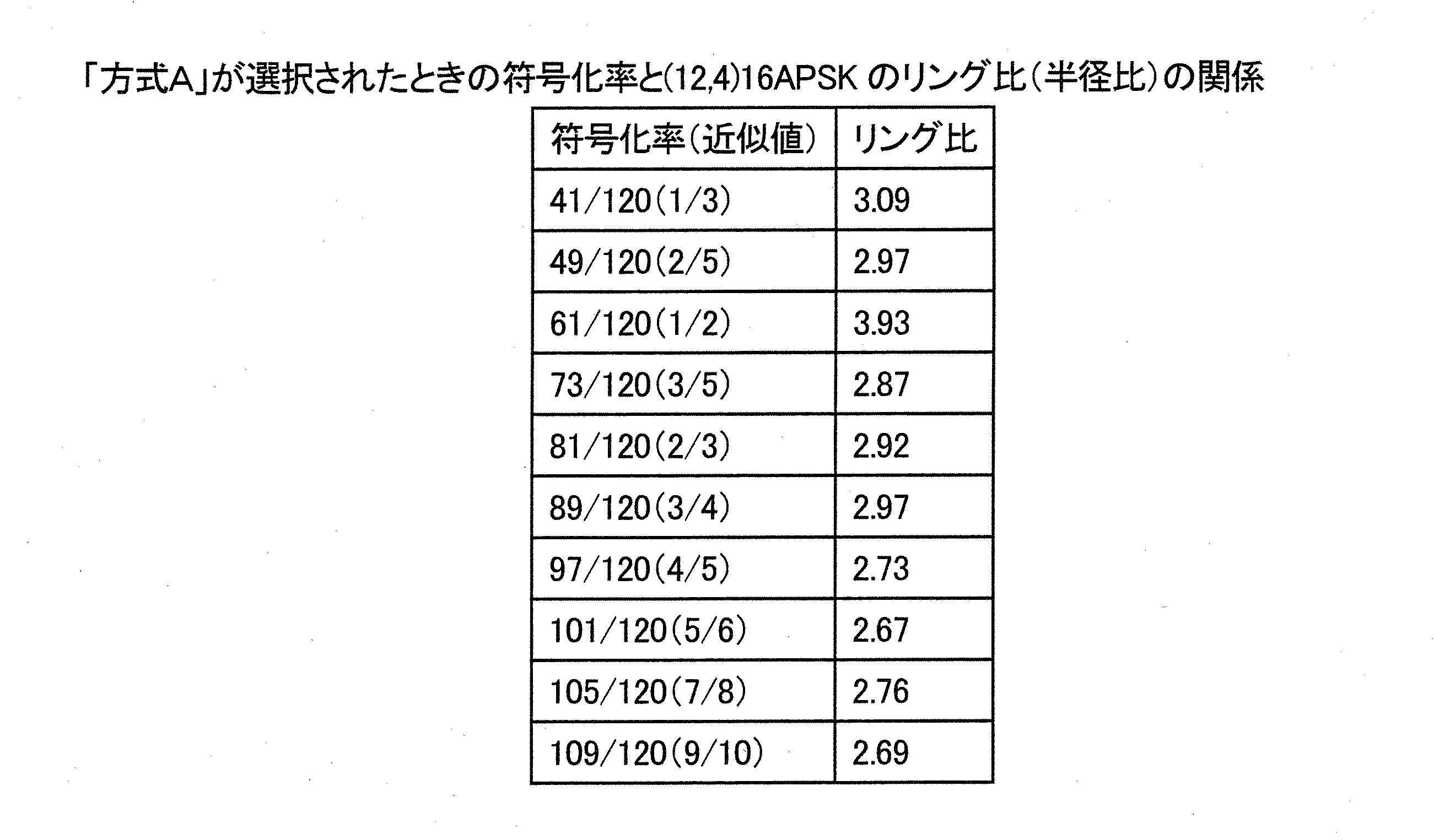
具体的には、上記で記載したb0、b1、b2、b3を使用する。b0、b1、b2、b3と誤り訂正符号の符号化率との関係は以下のとおりである。
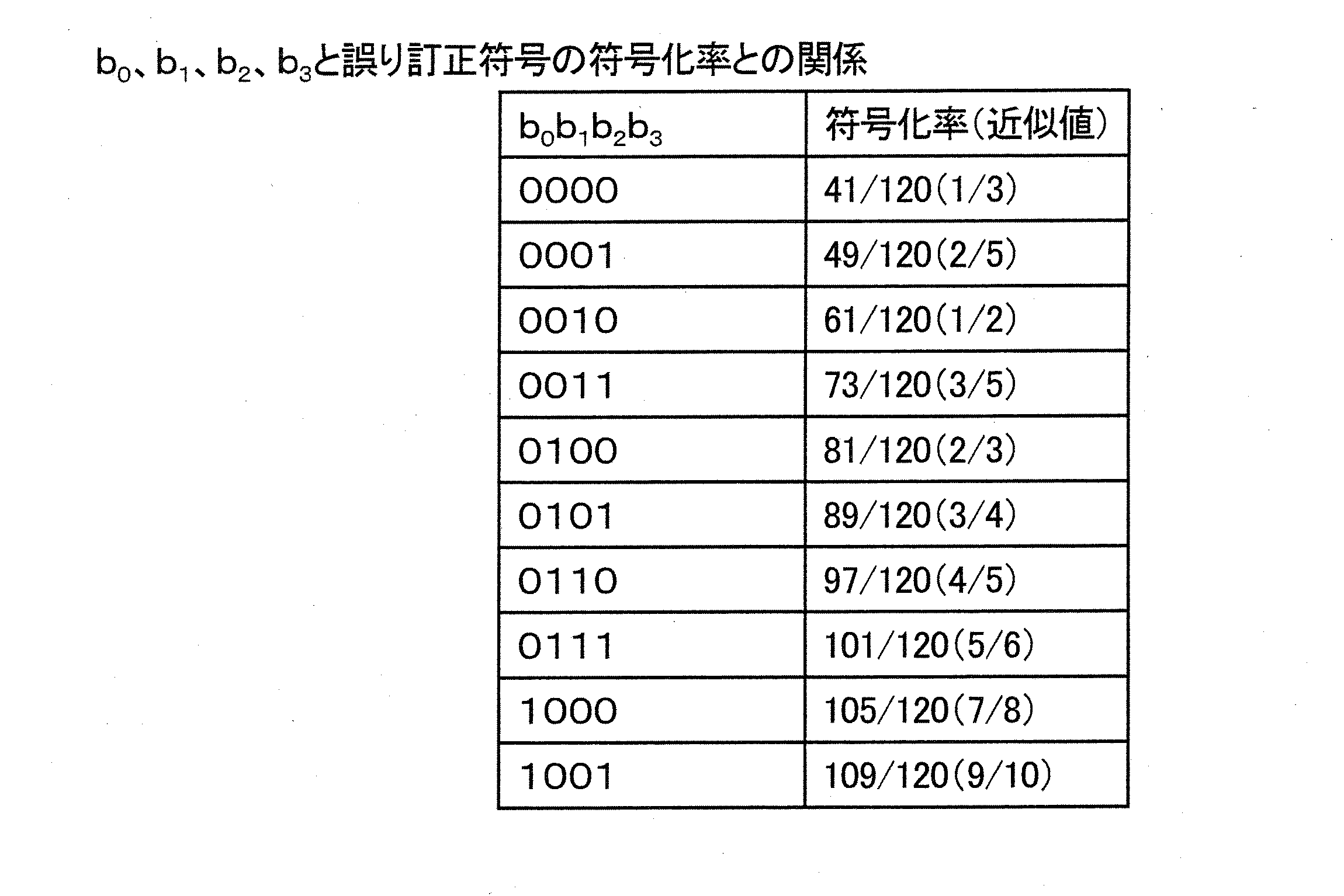
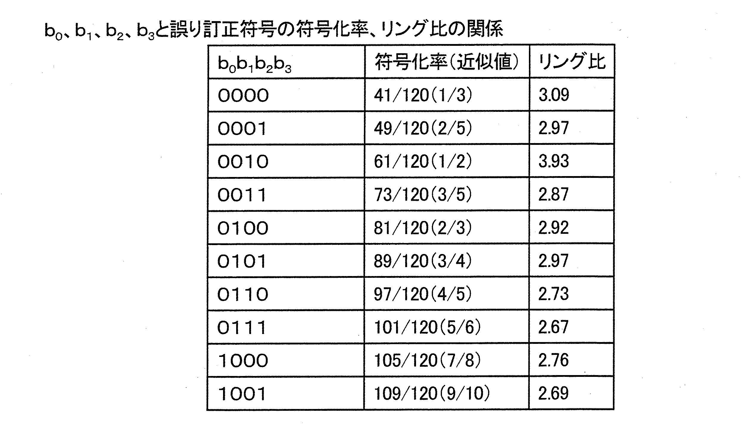
送信装置(送信局)が(b0b1b2b3)=(0000)と設定した場合、誤り訂正符号の符号化率は41/120であり、(12,4)16APSKを使用していた場合、リング比(半径比)は3.09となる。
送信装置(送信局)が(b0b1b2b3)=(0001)と設定した場合、誤り訂正符号の符号化率は49/120であり、(12,4)16APSKを使用していた場合、リング比(半径比)は2.97となる。
送信装置(送信局)が(b0b1b2b3)=(0010)と設定した場合、誤り訂正符号の符号化率は61/120であり、(12,4)16APSKを使用していた場合、リング比(半径比)は3.93となる。
送信装置(送信局)が(b0b1b2b3)=(0011)と設定した場合、誤り訂正符号の符号化率は73/120であり、(12,4)16APSKを使用していた場合、リング比(半径比)は2.87となる。
送信装置(送信局)が(b0b1b2b3)=(0100)と設定した場合、誤り訂正符号の符号化率は81/120であり、(12,4)16APSKを使用していた場合、リング比(半径比)は2.92となる。
送信装置(送信局)が(b0b1b2b3)=(0101)と設定した場合、誤り訂正符号の符号化率は89/120であり、(12,4)16APSKを使用していた場合、リング比(半径比)は2.97となる。
送信装置(送信局)が(b0b1b2b3)=(0110)と設定した場合、誤り訂正符号の符号化率は97/120であり、(12,4)16APSKを使用していた場合、リング比(半径比)は2.73となる。
送信装置(送信局)が(b0b1b2b3)=(0111)と設定した場合、誤り訂正符号の符号化率は101/120であり、(12,4)16APSKを使用していた場合、リング比(半径比)は2.67となる。
送信装置(送信局)が(b0b1b2b3)=(1000)と設定した場合、誤り訂正符号の符号化率は105/120であり、(12,4)16APSKを使用していた場合、リング比(半径比)は2.76となる。
送信装置(送信局)が(b0b1b2b3)=(1001)と設定した場合、誤り訂正符号の符号化率は109/120であり、(12,4)16APSKを使用していた場合、リング比(半径比)は2.69となる。
・「方式A」を使用していることを通知するために、TMCCの拡張識別をすべて"0"(16ビットすべてがゼロ)とし、TMCCの拡張領域の3598ビットをすべて"1"と設定する。
・誤り訂正符号の符号化率、(12,4)16APSKのリング比を推定可能とするために、b0b1b2b3を送信する。
を実施することになる。
そして、具体的な例として、<例1>~<例5>を以下で説明する。
例1では、「方式B」において、(12,4)16APSKのリング比のテーブルは複数種類用意されることで、ひとつの符号化率に対して異なるリング比が設定可能となっている。
図48に示すように、テーブル1、テーブル2、・・・、テーブル16、つまり、テーブル1からテーブル16の16種類のテーブルを用意する。
・・・
・誤り訂正符号の符号化率41/120、49/120、61/120、73/120、81/120、89/120、97/120、101/120、105/120、109/120それぞれに対し、b0b1b2b3の値、(12,4)16APSKのリ
ング比の関連づけが行われた複数のテーブルを用意する。
・使用したテーブルの情報を示すc0c1c2c3を送信装置(送信局)は送信する。
とすることで、送信装置は、データシンボルを生成するのに使用した(12,4)16APSKのリング比の情報を伝送することになる。
例2は、<例1>の変形例である。
そして、新たに、送信装置(送信局)はz0の設定を行う。「方式A」と同様の方法で(12,4)16APSKのリング比を決定する場合、z0=0と設定する。z0=0と設定した場合、b0、b1、b2、b3により、表16に基づき、誤り訂正符号の符号化率を指定し、表15から、(12,4)16APSKのリング比が決定することになる。(表17参照)
図49に示すように、テーブル1、テーブル2、・・・、テーブル16、つまり、テーブル1からテーブル16の16種類のテーブルを用意する。
・・・
例3は、リング比を示す値によりシグナリングを行うものであることを特徴としている。
例4は、メインテーブルにおける誤り訂正符号の符号化率および(12,4)16APSKのリング比を示すb0b1b2b3と、リング比の差分を示すy0y1y2y3y4y5とにより所望の(12,4)16APSKのリング比のシグナリングを実現するものである。
すると、以下のようになる。
・・・
(y0y1y2y3y4y5)=(011110)と送信装置(送信局)が設定した場合、(12,4)16APSKのリング比はh+0.4と設定するものとする。
(y0y1y2y3y4y5)=(011111)と送信装置(送信局)が設定した場合、(12,4)16APSKのリング比はh+0.2と設定するものとする。
(y0y1y2y3y4y5)=(100000)と送信装置(送信局)が設定した場合、(12,4)16APSKのリング比はh+0と設定するものとする。
(y0y1y2y3y4y5)=(100001)と送信装置(送信局)が設定した場合、(12,4)16APSKのリング比はh-0.2と設定するものとする。
(y0y1y2y3y4y5)=(100010)と送信装置(送信局)が設定した場合、(12,4)16APSKのリング比はh-0.4と設定するものとする。
・・・
したがって、送信装置は、(y0y1y2y3y4y5)を決定することで、メインテーブルにより決定した(12,4)16APSKのリング比hに対する補正値fが決定し、(12,4)16APSKのリング比をh+fに設定する。
例5は、メインテーブルにおける誤り訂正符号の符号化率および(12,4)16APSKのリング比を示すb0b1b2b3と、リング比の差分を示すy0y1y2y3y4y5とにより所望のリング比のシグナリングを実現するものである。
すると、以下のようになる。
・・・
(y0y1y2y3y4y5)=(011110)と送信装置(送信局)が設定した場合、(12,4)16APSKのリング比はh×1.2と設定するものとする。
(y0y1y2y3y4y5)=(011111)と送信装置(送信局)が設定した場合、(12,4)16APSKのリング比はh×1.1と設定するものとする。
(y0y1y2y3y4y5)=(100000)と送信装置(送信局)が設定した場合、(12,4)16APSKのリング比はh×1.0と設定するものとする。
(y0y1y2y3y4y5)=(100001)と送信装置(送信局)が設定した場合、(12,4)16APSKのリング比はh×0.9と設定するものとする。
(y0y1y2y3y4y5)=(100010)と送信装置(送信局)が設定した場合、(12,4)16APSKのリング比はh×0.8と設定するものとする。
・・・
したがって、送信装置は、(y0y1y2y3y4y5)を決定することで、メインテーブルにより決定した(12,4)16APSKのリング比hに対する補正係数gが決定し、(12,4)16APSKのリング比をh×gに設定する。
まず、送信装置は、「方式B」を選択しているのでd0="1"と設定する。
本実施の形態の送信方法に対応する受信装置について<例1>~<例5>に共通する構成について説明した後で各例の具体的な処理について説明する。
なお、本実施の形態で重要になることは、「TMCC情報シンボル群」に含まれる制御情報を制御情報推定部A216は推定し、制御信号として出力する点であり、このとき、制御信号には、上述のd0、z0、c0c1c2c3、b0b1b2b3、x0x1x2x3x4x5、y0y1y2y3y4y5の情報を含んでいるという点である。
デインターリーブ部A208は、対数尤度比、制御信号を入力とし、蓄積し、送信装置が用いたインターリーブに対応するデインターリーブ(データの並び換え)を行い、デインターリーブ後の対数尤度比を出力する。
・送信装置(送信局)が「方式A」で変調信号を送信した場合:
受信装置の制御情報推定部A216は、d0="0"と得られた場合、データシンボルは「方式A」で送信されたシンボルであると判断する。そして、b0b1b2b3の値を得ることで、データシンボルが(12,4)16APSKのシンボルであるとき、(12,4)16APSKのリング比を推定することになる。そして、デマッピング部A206は、これらの推定情報に基づき、データシンボルの復調を行う。
図53に示すように、受信装置の制御情報推定部A216は、d0="1"から「方式B」、c0c1c2c3="0001"およびb0b1b2b3="0000"からテーブル2の1行目の誤り訂正符号の符号化率41/120および(12,4)16APSKのリング比4.00と推定する。そして、デマッピング部A206は、これらの推定情報に基づき、データシンボルの復調を行う。
・送信装置(送信局)が「方式A」で変調信号を送信した場合:
受信装置の制御情報推定部A216は、d0="0"と得られた場合、データシンボルは「方式A」で送信されたシンボルであると判断する。そして、b0b1b2b3の値を得ることで、データシンボルが(12,4)16APSKのシンボルであるとき、(12,4)16APSKのリング比を推定することになる。そして、デマッピング部A206は、これらの推定情報に基づき、データシンボルの復調を行う。
図54に示すように、受信装置の制御情報推定部A216は、d0="1"、z0=0と得たとき、「方式Aのときと同様にリング比が設定されている」と判定し、b0、b1、b2、b3を得、表17から誤り訂正符号の符号化率と(12,4)16APSKのリング比を推定する。そして、デマッピング部A206は、これらの推定情報に基づき、データシンボルの復調を行う。
・送信装置(送信局)が「方式A」で変調信号を送信した場合:
受信装置の制御情報推定部A216は、d0="0"と得られた場合、データシンボルは「方式A」で送信されたシンボルであると判断する。そして、b0b1b2b3の値を得ることで、データシンボルが(12,4)16APSKのシンボルであるとき、(12,4)16APSKのリング比を推定することになる。そして、デマッピング部A206は、これらの推定情報に基づき、データシンボルの復調を行う。
図55に示すように、受信装置の制御情報推定部A216は、d0="1"から「方式B」、x0x1x2x3x4x5="000000"から(12,4)16APSKのリング比を2.00と推定する。そして、デマッピング部A206は、これらの推定情報に基づき、データシンボルの復調を行う。
・送信装置(送信局)が「方式A」で変調信号を送信した場合:
受信装置の制御情報推定部A216は、d0="0"と得られた場合、データシンボルは「方式A」で送信されたシンボルであると判断する。そして、b0b1b2b3の値を得ることで、データシンボルが(12,4)16APSKのシンボルであるとき、(12,4)16APSKのリング比を推定することになる。そして、デマッピング部A206は、これらの推定情報に基づき、データシンボルの復調を行う。
図56に示すように、受信装置の制御情報推定部A216は、d0="1"からデータシンボルは「方式B」のシンボルであると判断する。また、受信装置の制御情報推定部A216は、y0y1y2y3y4y5="011110"から差分を+0.4と推定する。また、b0b1b2b3="0000"を基に、差分を考慮する前の(12,4)16APSKのリング比を3.09と誤り訂正符号の符号化率を41/120と推定する。そして、両者を加算して3.09+0.4=3.49より(12,4)16APSKのリング比を3.49と推定する。そして、デマッピング部A206は、これらの推定情報に基づき、データシンボルの復調を行う。
・送信装置(送信局)が「方式A」で変調信号を送信した場合:
受信装置の制御情報推定部A216は、d0="0"と得られた場合、データシンボルは「方式A」で送信されたシンボルであると判断する。そして、b0b1b2b3の値を得ることで、データシンボルが(12,4)16APSKのシンボルであるとき、(12,4)16APSKのリング比を推定することになる。そして、デマッピング部A206は、これらの推定情報に基づき、データシンボルの復調を行う。
図57に示すように、受信装置の制御情報推定部A216は、d0="1"からデータシンボルは「方式B」のシンボルであると判断する。また、受信装置の制御情報推定部A216は、y0y1y2y3y4y5="100001"を基に差分を×0.9と推定する。また、b0b1b2b3="0000"を基に、差分を考慮する前の(12,4)16APSKのリング比を3.09と誤り訂
正符号の符号化率を41/120と推定する。そして、両者を乗算して3.09×0.9=2.78より(12,4)16APSKのリング比を2.78と推定する。そして、デマッピング部A206は、これらの推定情報に基づき、データシンボルの復調を行う。
この実施の形態では、実施の形態Cに基づいたパイロットシンボルの送信方法について説明する。
なお、リング比(例えば、(12,4)16APSKのリング比)の定義については、本実施の形態以前に定義したものであり、リング比は別の名称として、「半径比」と呼んでもよい。
本実施の形態では、上記の実施の形態Cで説明した送信方式(データシンボルの変調方式が(12,4)16APSK)におけるパイロットシンボルの構成例について説明する。
送信装置の電力増幅器の非線形性から、変調信号は、符号間(シンボル間)干渉が発生する。受信装置では、この符号間干渉を低減させることで、高いデータの受信品質を得ることができる。
送信装置(送信局)は、データシンボルを「衛星放送の方式を「方式B」、符号化率を41/120、(12,4)16APSKのリング比を4.00」で送信する場合、d0="1"、b0b1b2b3="0000"、c0c1c2c3="0001"とする。そして、「d0="1"、b0b1b2b3="0000"、c0c1c2c3="0001"」に基づき、送信装置(送信局)は、パイロットシンボルの変調方式・リング比をそれぞれ、(12,4)16APSK・リング比を4.00(ただし、(12,4)16APSK)と設定する。
(12,4)16APSKリング比4.00の[b3b2b1b0]=[0000]に対応する信号点(ベースバンド信号)のシンボル、
(12,4)16APSKリング比4.00の[b3b2b1b0]=[0001]に対応する信号点(ベースバンド信号)のシンボル、
(12,4)16APSKリング比4.00の[b3b2b1b0]=[0010]に対応する信号点(ベースバンド信号)のシンボル、
(12,4)16APSKリング比4.00の[b3b2b1b0]=[0011]に対応する信号点(ベースバンド信号)のシンボル、
(12,4)16APSKリング比4.00の[b3b2b1b0]=[0100]に対応する信号点(ベースバンド信号)のシンボル、
(12,4)16APSKリング比4.00の[b3b2b1b0]=[0101]に対応する信号点(ベースバンド信号)のシンボル、
(12,4)16APSKリング比4.00の[b3b2b1b0]=[0110]に対応する信号点(ベースバンド信号)のシンボル、
(12,4)16APSKリング比4.00の[b3b2b1b0]=[0111]に対応する信号点(ベースバンド信号)のシンボル、
(12,4)16APSKリング比4.00の[b3b2b1b0]=[1000]に対応する信号点(ベースバンド信号)のシンボル、
(12,4)16APSKリング比4.00の[b3b2b1b0]=[1001]に対応する信号点(ベースバンド信号)のシンボル、
(12,4)16APSKリング比4.00の[b3b2b1b0]=[1010]に対応する信号点(ベースバンド信号)のシンボル、
(12,4)16APSKリング比4.00の[b3b2b1b0]=[1011]に対応する信号点(ベースバンド信号)のシンボル、
(12,4)16APSKリング比4.00の[b3b2b1b0]=[1100]に対応する信号点(ベースバンド信号)のシンボル、
(12,4)16APSKリング比4.00の[b3b2b1b0]=[1101]に対応する信号点(ベースバンド信号)のシンボル、
(12,4)16APSKリング比4.00の[b3b2b1b0]=[1110]に対応する信号点(ベースバンド信号)のシンボル、
(12,4)16APSKリング比4.00の[b3b2b1b0]=[1111]に対応する信号点(ベースバンド信号)のシンボル、
をパイロットシンボルとして送信する。
(12,4)16APSKリング比Lの[b3b2b1b0]=[0000]に対応する信号点(ベースバンド信号)のシンボル、
(12,4)16APSKリング比Lの[b3b2b1b0]=[0001]に対応する信号点(ベースバンド信号)のシンボル、
(12,4)16APSKリング比Lの[b3b2b1b0]=[0010]に対応する信号点(ベースバンド信号)のシンボル、
(12,4)16APSKリング比Lの[b3b2b1b0]=[0011]に対応する信号点(ベースバンド信号)のシンボル、
(12,4)16APSKリング比Lの[b3b2b1b0]=[0100]に対応する信号点(ベースバンド信号)のシンボル、
(12,4)16APSKリング比Lの[b3b2b1b0]=[0101]に対応する信号点(ベースバンド信号)のシンボル、
(12,4)16APSKリング比Lの[b3b2b1b0]=[0110]に対応する信号点(ベースバンド信号)のシンボル、
(12,4)16APSKリング比Lの[b3b2b1b0]=[0111]に対応する信号点(ベースバンド信号)のシンボル、
(12,4)16APSKリング比Lの[b3b2b1b0]=[1000]に対応する信号点(ベースバンド信号)のシンボル、
(12,4)16APSKリング比Lの[b3b2b1b0]=[1001]に対応する信号点(ベースバンド信号)のシンボル、
(12,4)16APSKリング比Lの[b3b2b1b0]=[1010]に対応する信号点(ベースバンド信号)のシンボル、
(12,4)16APSKリング比Lの[b3b2b1b0]=[1011]に対応する信号点(ベースバンド信号)のシンボル、
(12,4)16APSKリング比Lの[b3b2b1b0]=[1100]に対応する信号点(ベースバンド信号)のシンボル、
(12,4)16APSKリング比Lの[b3b2b1b0]=[1101]に対応する信号点(ベースバンド信号)のシンボル、
(12,4)16APSKリング比Lの[b3b2b1b0]=[1110]に対応する信号点(ベースバンド信号)のシンボル、
(12,4)16APSKリング比Lの[b3b2b1b0]=[1111]に対応する信号点(ベースバンド信号)のシンボル、
をパイロットシンボルとして送信する。
送信装置(送信局)は、データシンボルを「衛星放送の方式を「方式B」、符号化率を41/120、(12,4)16APSKのリング比を4.00」で送信する場合、d0="1"、z0=1、b0b1b2b3="0000"、c0c1c2c3="0001"とする制御情報(TMCCの情報の一部)をデータシンボルとあわせて送信する。そして、「d0="1"、z0=1、b0b1b2b3="0000"、c0c1c2c3="0001"」に基づき、送信装置(送信局)は、パイロットシンボルの変調方式・リング比をそれぞれ、(12,4)16APSK・リング比を4.00(ただし、(12,4)16APSK)と設定する。
(12,4)16APSKリング比4.00の[b3b2b1b0]=[0000]に対応する信号点(ベースバンド信号)のシンボル、
(12,4)16APSKリング比4.00の[b3b2b1b0]=[0001]に対応する信号点(ベースバンド信号)のシンボル、
(12,4)16APSKリング比4.00の[b3b2b1b0]=[0010]に対応する信号点(ベースバンド信号)のシンボル、
(12,4)16APSKリング比4.00の[b3b2b1b0]=[0011]に対応する信号点(ベースバンド信号)のシンボル、
(12,4)16APSKリング比4.00の[b3b2b1b0]=[0100]に対応する信号点(ベースバンド信号)のシンボル、
(12,4)16APSKリング比4.00の[b3b2b1b0]=[0101]に対応する信号点(ベースバンド信号)のシンボル、
(12,4)16APSKリング比4.00の[b3b2b1b0]=[0110]に対応する信号点(ベースバンド信号)のシンボル、
(12,4)16APSKリング比4.00の[b3b2b1b0]=[0111]に対応する信号点(ベースバンド信号)のシンボル、
(12,4)16APSKリング比4.00の[b3b2b1b0]=[1000]に対応する信号点(ベースバンド信号)のシンボル、
(12,4)16APSKリング比4.00の[b3b2b1b0]=[1001]に対応する信号点(ベースバンド信号)のシンボル、
(12,4)16APSKリング比4.00の[b3b2b1b0]=[1010]に対応する信号点(ベースバンド信号)のシンボル、
(12,4)16APSKリング比4.00の[b3b2b1b0]=[1011]に対応する信号点(ベースバンド信号)のシンボル、
(12,4)16APSKリング比4.00の[b3b2b1b0]=[1100]に対応する信号点(ベースバンド信号)のシンボル、
(12,4)16APSKリング比4.00の[b3b2b1b0]=[1101]に対応する信号点(ベースバンド信号)のシンボル、
(12,4)16APSKリング比4.00の[b3b2b1b0]=[1110]に対応する信号点(ベースバンド信号)のシンボル、
(12,4)16APSKリング比4.00の[b3b2b1b0]=[1111]に対応する信号点(ベースバンド信号)のシンボル、
をパイロットシンボルとして送信する。
(12,4)16APSKリング比Lの[b3b2b1b0]=[0000]に対応する信号点(ベースバンド信号)のシンボル、
(12,4)16APSKリング比Lの[b3b2b1b0]=[0001]に対応する信号点(ベースバンド信号)のシンボル、
(12,4)16APSKリング比Lの[b3b2b1b0]=[0010]に対応する信号点(ベースバンド信号)のシンボル、
(12,4)16APSKリング比Lの[b3b2b1b0]=[0011]に対応する信号点(ベースバンド信号)のシンボル、
(12,4)16APSKリング比Lの[b3b2b1b0]=[0100]に対応する信号点(ベースバンド信号)のシンボル、
(12,4)16APSKリング比Lの[b3b2b1b0]=[0101]に対応する信号点(ベースバンド信号)のシンボル、
(12,4)16APSKリング比Lの[b3b2b1b0]=[0110]に対応する信号点(ベースバンド信号)のシンボル、
(12,4)16APSKリング比Lの[b3b2b1b0]=[0111]に対応する信号点(ベースバンド信号)のシンボル、
(12,4)16APSKリング比Lの[b3b2b1b0]=[1000]に対応する信号点(ベースバンド信号)のシンボル、
(12,4)16APSKリング比Lの[b3b2b1b0]=[1001]に対応する信号点(ベースバンド信号)のシンボル、
(12,4)16APSKリング比Lの[b3b2b1b0]=[1010]に対応する信号点(ベースバンド信号)のシンボル、
(12,4)16APSKリング比Lの[b3b2b1b0]=[1011]に対応する信号点(ベースバンド信号)のシンボル、
(12,4)16APSKリング比Lの[b3b2b1b0]=[1100]に対応する信号点(ベースバンド信号)のシンボル、
(12,4)16APSKリング比Lの[b3b2b1b0]=[1101]に対応する信号点(ベースバンド信号)のシンボル、
(12,4)16APSKリング比Lの[b3b2b1b0]=[1110]に対応する信号点(ベースバンド信号)のシンボル、
(12,4)16APSKリング比Lの[b3b2b1b0]=[1111]に対応する信号点(ベースバンド信号)のシンボル、
をパイロットシンボルとして送信する。
送信装置(送信局)は、データシンボルを「衛星放送の方式を「方式B」、 (12,4)16APSKのリング比を2.00」で送信する場合、d0="1"、x0x1x2x3x4x5="000000"とする制御情報(TMCCの情報の一部)をデータシンボルとあわせて送信する。そして、「d0="1"、x0x1x2x3x4x5="000000"」に基づき、送信装置(送信局)は、パイロットシンボルの変調方式・リング比をそれぞれ、(12,4)16APSK・リング比を2.00(ただし、(12,4)16APSK)と設定する。
(12,4)16APSKリング比2.00の[b3b2b1b0]=[0000]に対応する信号点(ベースバンド信号)のシンボル、
(12,4)16APSKリング比2.00の[b3b2b1b0]=[0001]に対応する信号点(ベースバンド信号)のシンボル、
(12,4)16APSKリング比2.00の[b3b2b1b0]=[0010]に対応する信号点(ベースバンド信号)のシンボル、
(12,4)16APSKリング比2.00の[b3b2b1b0]=[0011]に対応する信号点(ベースバンド信号)のシンボル、
(12,4)16APSKリング比2.00の[b3b2b1b0]=[0100]に対応する信号点(ベースバンド信号)のシンボル、
(12,4)16APSKリング比2.00の[b3b2b1b0]=[0101]に対応する信号点(ベースバンド信号)のシンボル、
(12,4)16APSKリング比2.00の[b3b2b1b0]=[0110]に対応する信号点(ベースバンド信号)のシンボル、
(12,4)16APSKリング比2.00の[b3b2b1b0]=[0111]に対応する信号点(ベースバンド信号)のシンボル、
(12,4)16APSKリング比2.00の[b3b2b1b0]=[1000]に対応する信号点(ベースバンド信号)のシンボル、
(12,4)16APSKリング比2.00の[b3b2b1b0]=[1001]に対応する信号点(ベースバンド信号)のシンボル、
(12,4)16APSKリング比2.00の[b3b2b1b0]=[1010]に対応する信号点(ベースバンド信号)のシンボル、
(12,4)16APSKリング比2.00の[b3b2b1b0]=[1011]に対応する信号点(ベースバンド信号)のシンボル、
(12,4)16APSKリング比2.00の[b3b2b1b0]=[1100]に対応する信号点(ベースバンド信号)のシンボル、
(12,4)16APSKリング比2.00の[b3b2b1b0]=[1101]に対応する信号点(ベースバンド信号)のシンボル、
(12,4)16APSKリング比2.00の[b3b2b1b0]=[1110]に対応する信号点(ベースバンド信号)のシンボル、
(12,4)16APSKリング比2.00の[b3b2b1b0]=[1111]に対応する信号点(ベースバンド信号)のシンボル、
をパイロットシンボルとして送信する。
(12,4)16APSKリング比Lの[b3b2b1b0]=[0000]に対応する信号点(ベースバンド信号)のシンボル、
(12,4)16APSKリング比Lの[b3b2b1b0]=[0001]に対応する信号点(ベースバンド信号)のシンボル、
(12,4)16APSKリング比Lの[b3b2b1b0]=[0010]に対応する信号点(ベースバンド信号)のシンボル、
(12,4)16APSKリング比Lの[b3b2b1b0]=[0011]に対応する信号点(ベースバンド信号)のシンボル、
(12,4)16APSKリング比Lの[b3b2b1b0]=[0100]に対応する信号点(ベースバンド信号)のシンボル、
(12,4)16APSKリング比Lの[b3b2b1b0]=[0101]に対応する信号点(ベースバンド信号)のシンボル、
(12,4)16APSKリング比Lの[b3b2b1b0]=[0110]に対応する信号点(ベースバンド信号)のシンボル、
(12,4)16APSKリング比Lの[b3b2b1b0]=[0111]に対応する信号点(ベースバンド信号)のシンボル、
(12,4)16APSKリング比Lの[b3b2b1b0]=[1000]に対応する信号点(ベースバンド信号)のシンボル、
(12,4)16APSKリング比Lの[b3b2b1b0]=[1001]に対応する信号点(ベースバンド信号)のシンボル、
(12,4)16APSKリング比Lの[b3b2b1b0]=[1010]に対応する信号点(ベースバンド信号)のシンボル、
(12,4)16APSKリング比Lの[b3b2b1b0]=[1011]に対応する信号点(ベースバンド信号)のシンボル、
(12,4)16APSKリング比Lの[b3b2b1b0]=[1100]に対応する信号点(ベースバンド信号)のシンボル、
(12,4)16APSKリング比Lの[b3b2b1b0]=[1101]に対応する信号点(ベースバンド信号)のシンボル、
(12,4)16APSKリング比Lの[b3b2b1b0]=[1110]に対応する信号点(ベースバンド信号)のシンボル、
(12,4)16APSKリング比Lの[b3b2b1b0]=[1111]に対応する信号点(ベースバンド信号)のシンボル、
をパイロットシンボルとして送信する。
送信装置(送信局)は、データシンボルを「衛星放送の方式を「方式B」、符号化率を41/120、(12,4)16APSKのリング比を3.49」で送信する場合、d0="1"、b0b1b2b3="0000"、y0y1y2y3y4y5="011110"とする制御情報(TMCCの情報の一部)をデータシンボルとあわせて送信する。そして、「d0="1"、b0b1b2b3="0000"、y0y1y2y3y4y5="011110"」に基づき、送信装置(送信局)は、パイロットシンボルの変調方式・リング比をそれぞれ、(12,4)16APSK・リング比を3.49(ただし、(12,4)16APSK)と設定する。
(12,4)16APSKリング比3.49の[b3b2b1b0]=[0000]に対応する信号点(ベースバンド信号)のシンボル、
(12,4)16APSKリング比3.49の[b3b2b1b0]=[0001]に対応する信号点(ベースバンド信号)のシンボル、
(12,4)16APSKリング比3.49の[b3b2b1b0]=[0010]に対応する信号点(ベースバンド信号)のシンボル、
(12,4)16APSKリング比3.49の[b3b2b1b0]=[0011]に対応する信号点(ベースバンド信号)のシンボル、
(12,4)16APSKリング比3.49の[b3b2b1b0]=[0100]に対応する信号点(ベースバンド信号)のシンボル、
(12,4)16APSKリング比3.49の[b3b2b1b0]=[0101]に対応する信号点(ベースバンド信号)のシンボル、
(12,4)16APSKリング比3.49の[b3b2b1b0]=[0110]に対応する信号点(ベースバンド信号)のシンボル、
(12,4)16APSKリング比3.49の[b3b2b1b0]=[0111]に対応する信号点(ベースバンド信号)のシンボル、
(12,4)16APSKリング比3.49の[b3b2b1b0]=[1000]に対応する信号点(ベースバンド信号)のシンボル、
(12,4)16APSKリング比3.49の[b3b2b1b0]=[1001]に対応する信号点(ベースバンド信号)のシンボル、
(12,4)16APSKリング比3.49の[b3b2b1b0]=[1010]に対応する信号点(ベースバンド信号)のシンボル、
(12,4)16APSKリング比3.49の[b3b2b1b0]=[1011]に対応する信号点(ベースバンド信号)のシンボル、
(12,4)16APSKリング比3.49の[b3b2b1b0]=[1100]に対応する信号点(ベースバンド信号)のシンボル、
(12,4)16APSKリング比3.49の[b3b2b1b0]=[1101]に対応する信号点(ベースバンド信号)のシンボル、
(12,4)16APSKリング比3.49の[b3b2b1b0]=[1110]に対応する信号点(ベースバンド信号)のシンボル、
(12,4)16APSKリング比3.49の[b3b2b1b0]=[1111]に対応する信号点(ベースバンド信号)のシンボル、
をパイロットシンボルとして送信する。
(12,4)16APSKリング比Lの[b3b2b1b0]=[0000]に対応する信号点(ベースバンド信号)のシンボル、
(12,4)16APSKリング比Lの[b3b2b1b0]=[0001]に対応する信号点(ベースバンド信号)のシンボル、
(12,4)16APSKリング比Lの[b3b2b1b0]=[0010]に対応する信号点(ベースバンド信号)のシンボル、
(12,4)16APSKリング比Lの[b3b2b1b0]=[0011]に対応する信号点(ベースバンド信号)のシンボル、
(12,4)16APSKリング比Lの[b3b2b1b0]=[0100]に対応する信号点(ベースバンド信号)のシンボル、
(12,4)16APSKリング比Lの[b3b2b1b0]=[0101]に対応する信号点(ベースバンド信号)のシンボル、
(12,4)16APSKリング比Lの[b3b2b1b0]=[0110]に対応する信号点(ベースバンド信号)のシンボル、
(12,4)16APSKリング比Lの[b3b2b1b0]=[0111]に対応する信号点(ベースバンド信号)のシンボル、
(12,4)16APSKリング比Lの[b3b2b1b0]=[1000]に対応する信号点(ベースバンド信号)のシンボル、
(12,4)16APSKリング比Lの[b3b2b1b0]=[1001]に対応する信号点(ベースバンド信号)のシンボル、
(12,4)16APSKリング比Lの[b3b2b1b0]=[1010]に対応する信号点(ベースバンド信号)のシンボル、
(12,4)16APSKリング比Lの[b3b2b1b0]=[1011]に対応する信号点(ベースバンド信号)のシンボル、
(12,4)16APSKリング比Lの[b3b2b1b0]=[1100]に対応する信号点(ベースバンド信号)のシンボル、
(12,4)16APSKリング比Lの[b3b2b1b0]=[1101]に対応する信号点(ベースバンド信号)のシンボル、
(12,4)16APSKリング比Lの[b3b2b1b0]=[1110]に対応する信号点(ベースバンド信号)のシンボル、
(12,4)16APSKリング比Lの[b3b2b1b0]=[1111]に対応する信号点(ベースバンド信号)のシンボル、
をパイロットシンボルとして送信する。
送信装置(送信局)は、データシンボルを「衛星放送の方式を「方式B」、符号化率を41/120、(12,4)16APSKのリング比を2.78」で送信する場合、d0="1"、b0b1b2b3="0000"、y0y1y2y3y4y5="100001"とする制御情報(TMCCの情報の一部)をデータシンボルとあわせて送信する。そして、「d0="1"、b0b1b2b3="0000"、y0y1y2y3y4y5="100001"」に基づき、送信装置(送信局)は、パイロットシンボルの変調方式・リング比をそれぞれ、(12,4)16APSK・リング比を2.78(ただし、(12,4)16APSK)と設定する。
(12,4)16APSKリング比2.78の[b3b2b1b0]=[0000]に対応する信号点(ベースバンド信号)のシンボル、
(12,4)16APSKリング比2.78の[b3b2b1b0]=[0001]に対応する信号点(ベースバンド信号)のシンボル、
(12,4)16APSKリング比2.78の[b3b2b1b0]=[0010]に対応する信号点(ベースバンド信号)のシンボル、
(12,4)16APSKリング比2.78の[b3b2b1b0]=[0011]に対応する信号点(ベースバンド信号)のシンボル、
(12,4)16APSKリング比2.78の[b3b2b1b0]=[0100]に対応する信号点(ベースバンド信号)のシンボル、
(12,4)16APSKリング比2.78の[b3b2b1b0]=[0101]に対応する信号点(ベースバンド信号)のシンボル、
(12,4)16APSKリング比2.78の[b3b2b1b0]=[0110]に対応する信号点(ベースバンド信号)のシンボル、
(12,4)16APSKリング比2.78の[b3b2b1b0]=[0111]に対応する信号点(ベースバンド信号)のシンボル、
(12,4)16APSKリング比2.78の[b3b2b1b0]=[1000]に対応する信号点(ベースバンド信号)のシンボル、
(12,4)16APSKリング比2.78の[b3b2b1b0]=[1001]に対応する信号点(ベースバンド信号)のシンボル、
(12,4)16APSKリング比2.78の[b3b2b1b0]=[1010]に対応する信号点(ベースバンド信号)のシンボル、
(12,4)16APSKリング比2.78の[b3b2b1b0]=[1011]に対応する信号点(ベースバンド信号)のシンボル、
(12,4)16APSKリング比2.78の[b3b2b1b0]=[1100]に対応する信号点(ベースバンド信号)のシンボル、
(12,4)16APSKリング比2.78の[b3b2b1b0]=[1101]に対応する信号点(ベースバンド信号)のシンボル、
(12,4)16APSKリング比2.78の[b3b2b1b0]=[1110]に対応する信号点(ベースバンド信号)のシンボル、
(12,4)16APSKリング比2.78の[b3b2b1b0]=[1111]に対応する信号点(ベースバンド信号)のシンボル、
をパイロットシンボルとして送信する。
(12,4)16APSKリング比Lの[b3b2b1b0]=[0000]に対応する信号点(ベースバンド信号)のシンボル、
(12,4)16APSKリング比Lの[b3b2b1b0]=[0001]に対応する信号点(ベースバンド信号)のシンボル、
(12,4)16APSKリング比Lの[b3b2b1b0]=[0010]に対応する信号点(ベースバンド信号)のシンボル、
(12,4)16APSKリング比Lの[b3b2b1b0]=[0011]に対応する信号点(ベースバンド信号)のシンボル、
(12,4)16APSKリング比Lの[b3b2b1b0]=[0100]に対応する信号点(ベースバンド信号)のシンボル、
(12,4)16APSKリング比Lの[b3b2b1b0]=[0101]に対応する信号点(ベースバンド信号)のシンボル、
(12,4)16APSKリング比Lの[b3b2b1b0]=[0110]に対応する信号点(ベースバンド信号)のシンボル、
(12,4)16APSKリング比Lの[b3b2b1b0]=[0111]に対応する信号点(ベースバンド信号)のシンボル、
(12,4)16APSKリング比Lの[b3b2b1b0]=[1000]に対応する信号点(ベースバンド信号)のシンボル、
(12,4)16APSKリング比Lの[b3b2b1b0]=[1001]に対応する信号点(ベースバンド信号)のシンボル、
(12,4)16APSKリング比Lの[b3b2b1b0]=[1010]に対応する信号点(ベースバンド信号)のシンボル、
(12,4)16APSKリング比Lの[b3b2b1b0]=[1011]に対応する信号点(ベースバンド信号)のシンボル、
(12,4)16APSKリング比Lの[b3b2b1b0]=[1100]に対応する信号点(ベースバンド信号)のシンボル、
(12,4)16APSKリング比Lの[b3b2b1b0]=[1101]に対応する信号点(ベースバンド信号)のシンボル、
(12,4)16APSKリング比Lの[b3b2b1b0]=[1110]に対応する信号点(ベースバンド信号)のシンボル、
(12,4)16APSKリング比Lの[b3b2b1b0]=[1111]に対応する信号点(ベースバンド信号)のシンボル、
をパイロットシンボルとして送信する。
送信装置(送信局)は、パイロットシンボルとして、
(12,4)16APSKリング比Lの[b3b2b1b0]=[0000]に対応する信号点(ベースバンド信号)のシンボルを複数回、
(12,4)16APSKリング比Lの[b3b2b1b0]=[0001]に対応する信号点(ベースバンド信号)のシンボルを複数回、
(12,4)16APSKリング比Lの[b3b2b1b0]=[0010]に対応する信号点(ベースバンド信号)のシンボルを複数回、
(12,4)16APSKリング比Lの[b3b2b1b0]=[0011]に対応する信号点(ベースバンド信号)のシンボルを複数回、
(12,4)16APSKリング比Lの[b3b2b1b0]=[0100]に対応する信号点(ベースバンド信号)のシンボルを複数回、
(12,4)16APSKリング比Lの[b3b2b1b0]=[0101]に対応する信号点(ベースバンド信号)のシンボルを複数回、
(12,4)16APSKリング比Lの[b3b2b1b0]=[0110]に対応する信号点(ベースバンド信号)のシンボルを複数回、
(12,4)16APSKリング比Lの[b3b2b1b0]=[0111]に対応する信号点(ベースバンド信号)のシンボルを複数回、
(12,4)16APSKリング比Lの[b3b2b1b0]=[1000]に対応する信号点(ベースバンド信号)のシンボルを複数回、
(12,4)16APSKリング比Lの[b3b2b1b0]=[1001]に対応する信号点(ベースバンド信号)のシンボルを複数回、
(12,4)16APSKリング比Lの[b3b2b1b0]=[1010]に対応する信号点(ベースバンド信号)のシンボルを複数回、
(12,4)16APSKリング比Lの[b3b2b1b0]=[1011]に対応する信号点(ベースバンド信号)のシンボルを複数回、
(12,4)16APSKリング比Lの[b3b2b1b0]=[1100]に対応する信号点(ベースバンド信号)のシンボルを複数回、
(12,4)16APSKリング比Lの[b3b2b1b0]=[1101]に対応する信号点(ベースバンド信号)のシンボルを複数回、
(12,4)16APSKリング比Lの[b3b2b1b0]=[1110]に対応する信号点(ベースバンド信号)のシンボルを複数回、
(12,4)16APSKリング比Lの[b3b2b1b0]=[1111]に対応する信号点(ベースバンド信号)のシンボルを複数回
送信してもよい。
(12,4)16APSKリング比Lの[b3b2b1b0]=[0000]に対応する信号点(ベースバンド信号)のシンボル、
(12,4)16APSKリング比Lの[b3b2b1b0]=[0001]に対応する信号点(ベースバンド信号)のシンボル、
(12,4)16APSKリング比Lの[b3b2b1b0]=[0010]に対応する信号点(ベースバンド信号)のシンボル、
(12,4)16APSKリング比Lの[b3b2b1b0]=[0011]に対応する信号点(ベースバンド信号)のシンボル、
(12,4)16APSKリング比Lの[b3b2b1b0]=[0100]に対応する信号点(ベースバンド信号)のシンボル、
(12,4)16APSKリング比Lの[b3b2b1b0]=[0101]に対応する信号点(ベースバンド信号)のシンボル、
(12,4)16APSKリング比Lの[b3b2b1b0]=[0110]に対応する信号点(ベースバンド信号)のシンボル、
(12,4)16APSKリング比Lの[b3b2b1b0]=[0111]に対応する信号点(ベースバンド信号)のシンボル、
(12,4)16APSKリング比Lの[b3b2b1b0]=[1000]に対応する信号点(ベースバンド信号)のシンボル、
(12,4)16APSKリング比Lの[b3b2b1b0]=[1001]に対応する信号点(ベースバンド信号)のシンボル、
(12,4)16APSKリング比Lの[b3b2b1b0]=[1010]に対応する信号点(ベースバンド信号)のシンボル、
(12,4)16APSKリング比Lの[b3b2b1b0]=[1011]に対応する信号点(ベースバンド信号)のシンボル、
(12,4)16APSKリング比Lの[b3b2b1b0]=[1100]に対応する信号点(ベースバンド信号)のシンボル、
(12,4)16APSKリング比Lの[b3b2b1b0]=[1101]に対応する信号点(ベースバンド信号)のシンボル、
(12,4)16APSKリング比Lの[b3b2b1b0]=[1110]に対応する信号点(ベースバンド信号)のシンボル、
(12,4)16APSKリング比Lの[b3b2b1b0]=[1111]に対応する信号点(ベースバンド信号)のシンボル、
の各シンボルの送信回数を等しくすると、高精度の伝搬路の歪み推定を、受信装置は行うことができるという利点がある。
当然であるが、本明細書において説明した実施の形態を複数組み合わせて、実施してもよい。
a, b) を対応させたとき、この点が極座標で[r, θ] とあらわされるなら、a=r×cosθ、b=r×sinθ


実施の形態12に、以下のように記載している。
「
<シグナリング>
本実施の形態では、上記の実施の形態10で説明した送信方式を用いた送信信号を、受信装置側において円滑に受信できるようにするために、TMCC情報としてシグナリングされる様々な情報の構成例について説明する。
図18は、高度広帯域衛星デジタル放送における送信信号のフレーム構成のイメージ図を示している。(ただし、高度広帯域衛星デジタル放送のフレーム構成を正確に図示したものではない。)なお、詳細については実施の形態3で説明したので、ここでは説明を省略する。
表18に変調方式の情報の構成を示している。表18において、例えば、「TMCC情報シンボル群」の「伝送モード/スロット情報」の伝送モードの変調方式を伝送するためのシンボルで伝送する4ビットが「0001」のとき、「データシンボル群で構成されるスロット」のシンボルを生成するための変調方式はπ/2シフトBPSK(Binary Phase Shift Keying)となる。
・・・

・・・

・・・

次に、送信装置700が送信した無線信号を受信する受信装置の動作について、図19の受信装置の構成図を用いて説明する。
同期・チャネル推定部1914は、フィルタ後のベースバンド信号を入力とし、送信装置が送信した、例えば、「同期シンボル群」「パイロットシンボル群」を用いて、時間同期、周波数同期、チャネル推定を行い、推定信号を出力する。
制御情報推定部1916は、フィルタ後のベースバンド信号を入力とし、「TMCC情報シンボル群」のような制御情報を含むシンボルを抽出し、復調・復号を行い、制御信号を出力する。
デインターリーブ部1908は、対数尤度比を入力とし、蓄積し、送信装置が用いたインターリーブに対応するデインターリーブ(データの並び換え)を行い、デインターリーブ後の対数尤度比を出力する。
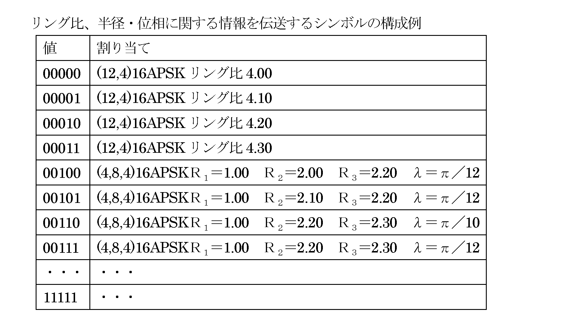
リング比、半径・位相に関する情報を伝送するシンボルにより、「00001」が伝送された場合、データシンボルは「(12,4)16APSKリング比4.10」のシンボルとなる。
リング比、半径・位相に関する情報を伝送するシンボルにより、「00010」が伝送された場合、データシンボルは「(12,4)16APSKリング比4.20」のシンボルとなる。
リング比、半径・位相に関する情報を伝送するシンボルにより、「00011」が伝送された場合、データシンボルは「(12,4)16APSKリング比4.30」のシンボルとなる。
リング比、半径・位相に関する情報を伝送するシンボルにより、「00100」が伝送された場合、データシンボルは「(4,8,4)16APSK半径R1=1.00、半径R2=2.00、半径R3=2.20、位相λ=π/12ラジアン」のシンボルとなる。
リング比、半径・位相に関する情報を伝送するシンボルにより、「00101」が伝送された場合、データシンボルは「(4,8,4)16APSK半径R1=1.00 、半径R2=2.10、半径R3=2.20、位相λ=π/12ラジアン」のシンボルとなる。
リング比、半径・位相に関する情報を伝送するシンボルにより、「00110」が伝送された場合、データシンボルは「(4,8,4)16APSK半径R1=1.00、半径R2=2.20、半径R3=2.30、位相λ=π/10ラジアン」のシンボルとなる。
リング比、半径・位相に関する情報を伝送するシンボルにより、「00111」が伝送された場合、データシンボルは「(4,8,4)16APSK半径R1=1.00、半径R2=2.20、半径R3=2.30、位相λ=π/12ラジアン」のシンボルとなる。
また、変調方式を伝送するためのシンボルにおいて、リング比、半径・位相の情報を含んでいてもよい。例を以下に示す。

変調方式の情報を伝送するシンボルにより、「00001」が伝送された場合、データシンボルは「(12,4)16APSKリング比4.10」のシンボルとなる。
変調方式の情報を伝送するシンボルにより、「00010」が伝送された場合、データシンボルは「(12,4)16APSKリング比4.20」のシンボルとなる。
変調方式の情報を伝送するシンボルにより、「00011」が伝送された場合、データシンボルは「(12,4)16APSKリング比4.30」のシンボルとなる。
変調方式の情報を伝送するシンボルにより、「00100」が伝送された場合、データシンボルは「(4,8,4)16APSK半径R1=1.00、半径R2=2.00、半径R3=2.20、位相λ=π/12ラジアン」のシンボルとなる。
変調方式の情報を伝送するシンボルにより、「00101」が伝送された場合、データシンボルは「4,8,4)16APSK半径R1=1.00 、半径R2=2.10、半径R3=2.20、位相λ=π/12ラジアン」のシンボルとなる。
変調方式の情報を伝送するシンボルにより、「00110」が伝送された場合、データシンボルは「(4,8,4)16APSK半径R1=1.00、半径R2=2.20、半径R3=2.30、位相λ=π/10ラジアン」のシンボルとなる。
変調方式の情報を伝送するシンボルにより、「00111」が伝送された場合、データシンボルは「(4,8,4)16APSK半径R1=1.00、半径R2=2.20、半径R3=2.30、位相λ=π/12ラジアン」のシンボルとなる。
変調方式の情報を伝送するシンボルにより、「11101」が伝送された場合、データシンボルは「8PSK」のシンボルとなる。
変調方式の情報を伝送するシンボルにより、「11110」が伝送された場合、データシンボルは「QPSK」のシンボルとなる。
変調方式の情報を伝送するシンボルにより、「11111」が伝送された場合、データシンボルは「π/2シフトBPSK」のシンボルとなる。
「第1の変調方式及び第2の変調方式を含む複数の変調方式から選択された変調方式を用いてデータシンボルを生成し、生成された前記データシンボルと前記選択された変調方式を示す制御情報とを送信する方法であって、前記第1の変調方式のマッピング及び第2の変調方式のマッピングは、
(i)送信データに応じて選択される信号点の数が互いに等しい、
(ii)同相I-直交Q平面において原点を中心とする複数の同心円に配置される信号点の数を、半径(振幅成分)の大きい円から順に並べた系列が同一ではない、
の両方を満たす」
となる。
「第1の変調方式及び第2の変調方式を含む複数の変調方式から選択された変調方式を用いてデータシンボルを生成し、生成された前記データシンボルと前記選択された変調方式を示す制御情報とを送信する方法であって、前記第1の変調方式のマッピング及び第2の変調方式のマッピングは、
(i)送信データに応じて選択される信号点の数が互いに等しい、
(ii)同相I-直交Q平面において原点を中心とする複数の同心円に配置される信号点の数を、半径(振幅成分)の大きい円から順に並べた系列が同一ではない、
の両方を満たし、
前記第1の変調方式及び前記第2の変調方式は、前記複数の同心円の半径(または直径)の比であるリング比を選択可能であり、前記制御情報は選択された変調方式とリング比を示す」となる。
Claims (2)
- 振幅および位相を偏移させる変調方式によりデータを送信する送信装置であって、
信号点配置および各信号点へのビットの割り付けが互いに相異なる第1変調方式と第2変調方式とを、シンボル毎に交互に選択する選択部と、
選択された変調方式に応じた信号点にマッピングを行うマッピング部と、
マッピングされた変調信号を送信する送信部とを備え、
前記第1変調方式は、IQ平面において、内円の円周上には4点の信号点が配置され、外円の円周上に12点の信号点が配置され、前記内円と外円とは同心円の関係にある16APSK変調であって、
16点の信号点を、内円の円周上の1点の信号点と前記IQ平面の原点から当該信号点に向けた方面にある外円の円周上の3点の信号点とからなる4つのグループに区分けした場合において、
同一グループ内における外円の円周上における隣接する信号点の組、および同一グループ内における外円の円周上の両端の信号点のいずれかと内円の信号点の組、のビットの割り付けの違いが1ビットであり、
異なるグループ間における、IQ平面上で最短となる、外円の円周上の信号点の組および内円の円周上の信号点の組、のビットの割り付けの違いが1ビットであり、
前記第2変調方式は、IQ平面において、内円の円周上には8点の信号点が配置され、外円の円周上に8点の信号点が配置され、前記内円と外円とは同心円の関係にある16APSK変調であって、
16点の信号点を、内円の円周上の8点の信号点からなる第1グループ、外円の円周上の8点の信号点からなる第2グループに区分けした場合において、
同一グループ内における円周上で隣接する信号点の組、のビットの割り付けの違いが1ビットである
ことを特徴とする送信装置。 - 前記第2変調方式における、内円の円周上の信号点と外円の円周上の信号点とは位相が揃っている請求項1記載の送信装置。
Priority Applications (10)
| Application Number | Priority Date | Filing Date | Title |
|---|---|---|---|
| CN201910047914.6A CN110086736B (zh) | 2013-04-12 | 2014-04-10 | 发送装置、发送方法、接收装置、接收方法 |
| JP2015511116A JP6350921B2 (ja) | 2013-04-12 | 2014-04-10 | 送信方法 |
| EP14783419.6A EP2985966B1 (en) | 2013-04-12 | 2014-04-10 | Transmission apparatus |
| EP17167201.7A EP3211848B1 (en) | 2013-04-12 | 2014-04-10 | Transmission method |
| US14/781,455 US9491026B2 (en) | 2013-04-12 | 2014-04-10 | Transmission method |
| CN201480020408.3A CN105103511B (zh) | 2013-04-12 | 2014-04-10 | 发送方法 |
| US15/271,626 US9942067B2 (en) | 2013-04-12 | 2016-09-21 | Transmission method |
| US15/904,579 US10177948B2 (en) | 2013-04-12 | 2018-02-26 | Transmission method |
| US16/201,389 US10476713B1 (en) | 2013-04-12 | 2018-11-27 | Transmission method |
| US16/585,522 US10742459B2 (en) | 2013-04-12 | 2019-09-27 | Transmission method |
Applications Claiming Priority (12)
| Application Number | Priority Date | Filing Date | Title |
|---|---|---|---|
| JP2013084271 | 2013-04-12 | ||
| JP2013-084270 | 2013-04-12 | ||
| JP2013084270 | 2013-04-12 | ||
| JP2013-084269 | 2013-04-12 | ||
| JP2013-084271 | 2013-04-12 | ||
| JP2013084269 | 2013-04-12 | ||
| JP2013099607 | 2013-05-09 | ||
| JP2013-099607 | 2013-05-09 | ||
| JP2013099606 | 2013-05-09 | ||
| JP2013-099606 | 2013-05-09 | ||
| JP2013-099605 | 2013-05-09 | ||
| JP2013099605 | 2013-05-09 |
Related Child Applications (2)
| Application Number | Title | Priority Date | Filing Date |
|---|---|---|---|
| US14/781,455 A-371-Of-International US9491026B2 (en) | 2013-04-12 | 2014-04-10 | Transmission method |
| US15/271,626 Continuation US9942067B2 (en) | 2013-04-12 | 2016-09-21 | Transmission method |
Publications (1)
| Publication Number | Publication Date |
|---|---|
| WO2014167861A1 true WO2014167861A1 (ja) | 2014-10-16 |
Family
ID=51689279
Family Applications (1)
| Application Number | Title | Priority Date | Filing Date |
|---|---|---|---|
| PCT/JP2014/002064 Ceased WO2014167861A1 (ja) | 2013-04-12 | 2014-04-10 | 送信方法 |
Country Status (5)
| Country | Link |
|---|---|
| US (5) | US9491026B2 (ja) |
| EP (2) | EP3211848B1 (ja) |
| JP (2) | JP6350921B2 (ja) |
| CN (2) | CN110086736B (ja) |
| WO (1) | WO2014167861A1 (ja) |
Cited By (4)
| Publication number | Priority date | Publication date | Assignee | Title |
|---|---|---|---|---|
| JP2019103115A (ja) * | 2017-11-29 | 2019-06-24 | パナソニックIpマネジメント株式会社 | 放送受信装置、テレビジョン受像機及び非線形歪みの推定方法 |
| KR20200083864A (ko) * | 2018-12-31 | 2020-07-09 | 강릉원주대학교산학협력단 | 직교진폭변조의 복조 장치 및 방법 |
| CN116097627A (zh) * | 2020-09-01 | 2023-05-09 | 奥兰治 | 利用相移极化星座降低papr的电信方法和对应装置 |
| US11996882B2 (en) | 2021-11-29 | 2024-05-28 | Uif (University Industry Foundation), Yonsei University | Impulse wireless communication system |
Families Citing this family (20)
| Publication number | Priority date | Publication date | Assignee | Title |
|---|---|---|---|---|
| WO2014167861A1 (ja) * | 2013-04-12 | 2014-10-16 | パナソニック インテレクチュアル プロパティ コーポレーション オブ アメリカ | 送信方法 |
| WO2016079180A1 (en) * | 2014-11-19 | 2016-05-26 | Lantiq Beteiligungs-GmbH & Co.KG | Link loss detection |
| JP6507047B2 (ja) * | 2015-02-10 | 2019-04-24 | 日本放送協会 | 送信装置、受信装置、及び半導体チップ |
| EP3223446A1 (en) * | 2016-03-22 | 2017-09-27 | Xieon Networks S.à r.l. | A method for protecting a link in an optical network |
| LU93085B1 (en) * | 2016-05-24 | 2017-11-29 | Univ Luxembourg | Data transmission method and device |
| CN107623565B (zh) * | 2016-07-15 | 2020-08-14 | 华为技术有限公司 | 基于多信道传输信号的方法和装置 |
| WO2018030204A1 (ja) * | 2016-08-12 | 2018-02-15 | パナソニック インテレクチュアル プロパティ コーポレーション オブ アメリカ | 送信装置、受信装置、送信方法および受信方法 |
| US20180124762A1 (en) * | 2016-10-31 | 2018-05-03 | Futurewei Technologies, Inc. | Quantization-Based Modulation and Coding Scheme for Mobile Fronthaul |
| US10585732B1 (en) * | 2017-01-11 | 2020-03-10 | Seagate Technology Llc | Error categorization based on bit information |
| US10320486B1 (en) | 2018-03-05 | 2019-06-11 | Mitsubishi Electric Research Laboratories, Inc. | Optical signal transmitter and optical signal encoder using constant modulus formats, and method for generating modulation codes |
| FR3093877B1 (fr) * | 2019-03-15 | 2022-04-01 | Commissariat Energie Atomique | Méthode de modulation numérique d’ordre élevé robuste au bruit de phase |
| CN113055067B (zh) * | 2019-12-27 | 2024-04-26 | 中兴通讯股份有限公司 | 下行信号处理方法、装置及基站 |
| CN113746775B (zh) * | 2020-05-30 | 2023-08-04 | 华为技术有限公司 | 一种信号发送方法、信号接收方法与相关装置 |
| WO2023283885A1 (zh) * | 2021-07-15 | 2023-01-19 | 株式会社Ntt都科摩 | 电子设备和调制方法 |
| EP4391469B1 (en) * | 2021-08-19 | 2026-04-15 | NTT, Inc. | Wireless communication system, wireless communication method, and reception apparatus |
| JP7647941B2 (ja) * | 2022-02-07 | 2025-03-18 | 日本電信電話株式会社 | 無線通信方法、無線通信システムおよび無線送信装置 |
| US11736320B2 (en) * | 2022-02-14 | 2023-08-22 | Ultralogic 6G, Llc | Multiplexed amplitude-phase modulation for 5G/6G noise mitigation |
| US12250100B2 (en) * | 2022-02-14 | 2025-03-11 | David E. Newman | Selecting a modulation scheme responsive to fault types in 5G/6G |
| US11799700B1 (en) * | 2022-08-31 | 2023-10-24 | Qualcomm Incorporated | Decoding multi-level coded (MLC) systems |
| CN120165808A (zh) * | 2023-12-14 | 2025-06-17 | 北京三星通信技术研究有限公司 | 由无线通信系统中的第一节点执行的方法以及第一节点 |
Citations (7)
| Publication number | Priority date | Publication date | Assignee | Title |
|---|---|---|---|---|
| JPH11220505A (ja) * | 1998-01-30 | 1999-08-10 | Matsushita Electric Ind Co Ltd | 変調方式とそれを用いた無線通信システム |
| JP2000216835A (ja) * | 1999-01-22 | 2000-08-04 | Hitachi Denshi Ltd | 畳み込み符号軟判定復号方式の受信装置 |
| JP2002261851A (ja) * | 2001-02-27 | 2002-09-13 | Matsushita Electric Ind Co Ltd | 通信装置及び伝送方式選択方法 |
| JP2004201286A (ja) * | 2002-12-04 | 2004-07-15 | Matsushita Electric Ind Co Ltd | データ送信方法とデータ受信方法およびそれらを用いた送信装置と受信装置 |
| JP2006217328A (ja) * | 2005-02-04 | 2006-08-17 | Sony Ericsson Mobilecommunications Japan Inc | 無線通信システム、送信装置、受信装置、送信方法および受信方法 |
| JP2009147637A (ja) * | 2007-12-13 | 2009-07-02 | Panasonic Corp | 無線送信装置、無線送信方法および無線通信システム |
| JP2013016953A (ja) | 2011-07-01 | 2013-01-24 | Hitachi Kokusai Electric Inc | 無線通信システム |
Family Cites Families (91)
| Publication number | Priority date | Publication date | Assignee | Title |
|---|---|---|---|---|
| US5068752A (en) * | 1987-09-29 | 1991-11-26 | Matsushita Electric Industrial Co., Ltd. | Apparatus for recording/reproducing a digital audio signal with a video signal |
| US5113412A (en) * | 1990-06-08 | 1992-05-12 | General Datacomm, Inc. | Method and apparatus for mapping an eight dimensional constellation of a convolutionally coded communication system |
| US5048056A (en) * | 1990-06-08 | 1991-09-10 | General Datacomm, Inc. | Method and apparatus for mapping an eight dimensional constellation of a convolutionally coded communication system |
| USRE42643E1 (en) * | 1991-03-27 | 2011-08-23 | Panasonic Corporation | Communication system |
| CA2106844C (en) * | 1991-03-28 | 1998-12-01 | John David Brownlie | Tcm scheme with fractional bit rates, framing signals and constellation shaping |
| US5119403A (en) * | 1991-04-09 | 1992-06-02 | Racal Data Communications Inc. | Superframes |
| US5185763A (en) * | 1991-04-09 | 1993-02-09 | Racal-Datacom, Inc. | Data bit to constellation symbol mapper |
| SG47627A1 (en) * | 1991-06-03 | 1998-04-17 | British Telecomm | Radio system |
| US5892879A (en) * | 1992-03-26 | 1999-04-06 | Matsushita Electric Industrial Co., Ltd. | Communication system for plural data streams |
| JPH06237275A (ja) * | 1993-02-10 | 1994-08-23 | Fujitsu Ltd | 特殊アイパターンおよび特殊アイパターンを用いた変復調方式 |
| US5467374A (en) * | 1993-10-29 | 1995-11-14 | General Electric Company | Low complexity adaptive equalizer for U.S. digital cellular radio receivers |
| US5371471A (en) * | 1993-10-29 | 1994-12-06 | General Electric Company | Low complexity adaptive equalizer radio receiver employing direct reference state updates |
| US5488635A (en) * | 1993-10-29 | 1996-01-30 | General Electric Company | Low complexity adaptive equalizer radio receiver employing reduced complexity branch metric calculation |
| JPH07143185A (ja) * | 1993-11-18 | 1995-06-02 | Toshiba Corp | 重み付け伝送方式及びその装置 |
| JPH07321765A (ja) * | 1994-05-30 | 1995-12-08 | Nippon Hoso Kyokai <Nhk> | 階層化変調方式および送受信装置 |
| US5659578A (en) * | 1994-11-23 | 1997-08-19 | At&T Wireless Services, Inc. | High rate Reed-Solomon concatenated trellis coded 16 star QAM system for transmission of data over cellular mobile radio |
| US5675590A (en) * | 1994-11-23 | 1997-10-07 | At&T Wireless Services, Inc. | Cyclic trellis coded modulation |
| US6889356B1 (en) * | 1994-11-23 | 2005-05-03 | Cingular Wireless Ii, Llc | Cyclic trellis coded modulation |
| JP3454623B2 (ja) * | 1995-11-28 | 2003-10-06 | 三洋電機株式会社 | π/4シフトQPSK直交変調装置 |
| US5815531A (en) * | 1996-06-12 | 1998-09-29 | Ericsson Inc. | Transmitter for encoded data bits |
| JP2978792B2 (ja) * | 1996-10-31 | 1999-11-15 | 株式会社次世代デジタルテレビジョン放送システム研究所 | 軟判定方式及び受信装置 |
| US6137829A (en) * | 1997-03-05 | 2000-10-24 | Paradyne Corporation | System and method for transmitting special marker symbols |
| US6046629A (en) * | 1997-06-12 | 2000-04-04 | Hitachi, Ltd. | Method of an apparatus for demodulating amplitude-modulated signals in an amplitude phase shift keying (APSK) system |
| US6005897A (en) * | 1997-12-16 | 1999-12-21 | Mccallister; Ronald D. | Data communication system and method therefor |
| DE69916151T2 (de) * | 1998-01-30 | 2005-04-21 | Matsushita Electric Industrial Co Ltd | Datenübertragung mit einer Zusammensetzung von Modulationsarten |
| JP3166705B2 (ja) * | 1998-04-16 | 2001-05-14 | 松下電器産業株式会社 | 無線装置及び送信方法 |
| US6567475B1 (en) * | 1998-12-29 | 2003-05-20 | Ericsson Inc. | Method and system for the transmission, reception and processing of 4-level and 8-level signaling symbols |
| US6608868B1 (en) * | 1999-01-19 | 2003-08-19 | Matsushita Electric Industrial Co., Ltd. | Apparatus and method for digital wireless communications |
| US6392500B1 (en) * | 1999-04-27 | 2002-05-21 | Sicom, Inc. | Rotationally invariant digital communications |
| US6259744B1 (en) * | 1999-06-01 | 2001-07-10 | Motorola, Inc. | Method and apparatus for mapping bits to an information burst |
| US6356586B1 (en) * | 1999-09-03 | 2002-03-12 | Lucent Technologies, Inc. | Methods and apparatus for parallel decision-feedback decoding in a communication system |
| US6400928B1 (en) * | 1999-11-19 | 2002-06-04 | Telefonaktiebolaget L M Ericsson (Publ) | Method and system for blind detection of modulation |
| US6421398B1 (en) * | 2000-01-28 | 2002-07-16 | Alcatel Canada Inc. | Modulation system having on-line IQ calibration |
| DE10008543A1 (de) * | 2000-02-24 | 2001-08-30 | Bosch Gmbh Robert | Codierverfahren und Verwendung eines Empfangsgeräts mit einem Faltungsdecoder |
| US6690738B1 (en) * | 2000-10-20 | 2004-02-10 | Lockheed Martin Corp. | Trellis coded modulation system employing a flexible trellis coded modulation decoder |
| EP1278344A1 (en) * | 2001-02-27 | 2003-01-22 | Matsushita Electric Industrial Co., Ltd. | Decoder and decoding method |
| US6865235B2 (en) * | 2001-03-06 | 2005-03-08 | Agere Systems Inc. | Multi-protocol modulator |
| US7006578B2 (en) * | 2001-10-23 | 2006-02-28 | Northrop Grumman Corporation | Constellation mapping for modulated communications |
| CN1493137A (zh) * | 2001-11-14 | 2004-04-28 | 连宇通信有限公司 | 一种用于数字移动通信系统的正交振幅调制方法 |
| US7062700B2 (en) * | 2002-05-31 | 2006-06-13 | Broadcom Corporation | 16 QAM and 16 APSK TTCM (Turbo Trellis Coded Modulation) with minimum bandwidth efficiency of 3 bit/s/Hz using a rate 2/4 constituent encoder |
| US7210092B1 (en) * | 2002-05-31 | 2007-04-24 | Broadcom Corporation | Symbol by symbol variable constellation type and/or mapping capable communication device |
| US7123663B2 (en) * | 2002-06-04 | 2006-10-17 | Agence Spatiale Europeenne | Coded digital modulation method for communication system |
| US7577207B2 (en) * | 2002-07-03 | 2009-08-18 | Dtvg Licensing, Inc. | Bit labeling for amplitude phase shift constellation used with low density parity check (LDPC) codes |
| EP1413059B9 (en) * | 2002-07-03 | 2015-09-02 | Dtvg Licensing, Inc | Bit-interleaved coded modulation using low density parity check (ldpc) codes |
| EP1537709B1 (en) * | 2002-08-28 | 2018-02-14 | Nxp B.V. | Method for generating a digital i/q signal in a tdma transmitter and corresponding modulator |
| JP3738997B2 (ja) * | 2002-12-05 | 2006-01-25 | 株式会社日立国際電気 | 通信方法 |
| US7376075B1 (en) * | 2003-09-26 | 2008-05-20 | Conexant Systems, Inc. | Circular constellations with coherent gain/differential phase and pilots |
| US7394869B2 (en) * | 2004-04-02 | 2008-07-01 | Broadcom Corporation | RF transmitter architecture for continuous switching between modulation modes |
| US7324613B2 (en) * | 2003-11-25 | 2008-01-29 | University Of Florida Research Foundation, Inc. | Multi-layer differential phase shift keying with bit-interleaved coded modulation and OFDM |
| KR100496155B1 (ko) * | 2003-12-27 | 2005-06-20 | 한국전자통신연구원 | 코셋 매핑을 이용한 터보 티씨엠 복호 장치 및 그 방법 |
| JP4341418B2 (ja) * | 2004-01-30 | 2009-10-07 | 日本電気株式会社 | 直交変調器の調整装置及び調整方法並びに通信装置とプログラム |
| US7958425B2 (en) * | 2004-02-19 | 2011-06-07 | Trelliware Technologies, Inc. | Method and apparatus for communications using turbo like codes |
| JP4448168B2 (ja) * | 2004-03-04 | 2010-04-07 | クゥアルコム・インコーポレイテッド | 異なる変調フォーマットにおいて送信された隣接するシンボルバースト間でスムーズな遷移を達成するための方法および装置 |
| US8009761B2 (en) * | 2004-06-24 | 2011-08-30 | Qualcomm Incorporation | Unified modulator for continuous phase modulation and phase-shift keying |
| US7515642B2 (en) * | 2004-08-25 | 2009-04-07 | Broadcom Corporation | LDPC (Low Density Parity Check) coded 128 DSQ (Double Square QAM) constellation modulation and associated labeling |
| EP1971098A4 (en) * | 2005-12-27 | 2012-05-02 | Fujitsu Ltd | DIGITAL WIRELESS COMMUNICATION PROCESS, TRANSMITTER AND RECEIVER WITH A MULTI-RANGE MODULATION SCHEME |
| EP1992137A2 (en) * | 2006-02-08 | 2008-11-19 | QUALCOMM Incorporated | Spectral shaping to reduce peak-to-average ratio in wireless communication |
| KR100795226B1 (ko) * | 2006-06-20 | 2008-01-17 | 강릉대학교산학협력단 | 삼각 형태의 성상도를 이용하는 디지털 신호 변조 방법 및장치 |
| US20110173509A1 (en) * | 2006-09-18 | 2011-07-14 | Availink, Inc. | Bit mapping scheme for an ldpc coded 16apsk system |
| WO2008034288A1 (en) * | 2006-09-18 | 2008-03-27 | Juntan Zhang | Bit mapping scheme for an ldpc coded 16apsk system |
| EP2129070B1 (en) * | 2007-02-23 | 2018-12-26 | Nippon Hoso Kyokai | Digital data transmitting device and digital data receiving device |
| JP2008245128A (ja) * | 2007-03-28 | 2008-10-09 | Toshiba Corp | Ofdmを用いた無線送信装置と方法及び無線受信装置と方法 |
| KR101276863B1 (ko) * | 2007-04-11 | 2013-06-18 | 엘지전자 주식회사 | 디지털 방송 신호 수신 장치 및 방법 |
| JP4455630B2 (ja) * | 2007-08-29 | 2010-04-21 | 株式会社東芝 | 送信機および受信機 |
| US8040985B2 (en) * | 2007-10-09 | 2011-10-18 | Provigent Ltd | Decoding of forward error correction codes in the presence of phase noise |
| FR2927754B1 (fr) * | 2008-02-19 | 2010-03-26 | Get Enst Bretagne Groupe Des E | Procede de transmission, dispositif, produit programme d'ordinateur et signal correspondants. |
| US8218679B2 (en) * | 2008-03-17 | 2012-07-10 | Modesat Communications OÜ | Method and system for creating quadrature modulation signal constellations with arbitrary spectral efficiency |
| JP5059949B2 (ja) * | 2008-11-28 | 2012-10-31 | 株式会社日立製作所 | 光電界送信器及び光伝送システム |
| US8406338B2 (en) * | 2009-03-04 | 2013-03-26 | Allen LeRoy Limberg | Terminated concatenated convolutional coding of M/H group data in 8VSB digital television signals |
| US8279964B2 (en) * | 2009-04-09 | 2012-10-02 | Indian Institute Of Science | Data transmission in wireless communication system |
| DE102009030675B4 (de) * | 2009-06-26 | 2019-05-16 | Rohde & Schwarz Gmbh & Co. Kg | Verfahren und Vorrichtung zum Senden und Empfangen von Signalen mit Modulationskompression |
| GB2471876B (en) * | 2009-07-15 | 2011-08-31 | Toshiba Res Europ Ltd | Data communication method and apparatus |
| US8793745B2 (en) * | 2010-04-14 | 2014-07-29 | Hughes Network Systems, Llc | Method and apparatus for data rate controller for a code block multiplexing scheme |
| CN102986155B (zh) * | 2010-06-17 | 2015-09-02 | 松下电器(美国)知识产权公司 | 预编码方法、发送装置 |
| WO2012004890A1 (ja) * | 2010-07-09 | 2012-01-12 | 株式会社日立製作所 | 光受信器及び光伝送システム |
| JP5578360B2 (ja) * | 2010-09-14 | 2014-08-27 | ソニー株式会社 | 受信装置および方法、並びにプログラム |
| CN103004121B (zh) * | 2010-12-10 | 2016-01-27 | 松下电器(美国)知识产权公司 | 信号生成方法及信号生成装置 |
| US20120224651A1 (en) * | 2011-03-03 | 2012-09-06 | Yutaka Murakami | Signal generation method and signal generation apparatus |
| US8656245B2 (en) * | 2011-04-13 | 2014-02-18 | California Institute Of Technology | Method of error floor mitigation in low-density parity-check codes |
| JP5657782B2 (ja) * | 2011-04-19 | 2015-01-21 | パナソニック インテレクチュアル プロパティ コーポレーション オブアメリカPanasonic Intellectual Property Corporation of America | 信号生成方法及び信号生成装置 |
| JP5618944B2 (ja) * | 2011-08-19 | 2014-11-05 | 株式会社東芝 | 無線受信装置 |
| US9634878B1 (en) * | 2011-09-08 | 2017-04-25 | See Scan, Inc. | Systems and methods for data transfer using self-synchronizing quadrature amplitude modulation (QAM) |
| US8693888B2 (en) * | 2012-01-10 | 2014-04-08 | Alcatel Lucent | Noise-resilient constellations for an optical transport system |
| US9049058B2 (en) * | 2012-12-21 | 2015-06-02 | Broadcom Corporation | Fine step blended modulation communications |
| KR102356963B1 (ko) * | 2013-01-11 | 2022-02-08 | 선 페이턴트 트러스트 | 데이터 처리방법, 프리코딩 방법, 통신장치 |
| WO2014123017A1 (ja) * | 2013-02-08 | 2014-08-14 | ソニー株式会社 | データ処理装置、及びデータ処理方法 |
| CN104969476B (zh) * | 2013-02-08 | 2019-05-07 | 索尼公司 | 数据处理装置以及数据处理方法 |
| US20150358032A1 (en) * | 2013-02-08 | 2015-12-10 | Sony Corporation | Data processing device and data processing method |
| WO2014167861A1 (ja) * | 2013-04-12 | 2014-10-16 | パナソニック インテレクチュアル プロパティ コーポレーション オブ アメリカ | 送信方法 |
| JP6323753B2 (ja) * | 2013-06-14 | 2018-05-16 | サン パテント トラスト | 送信方法 |
| WO2015001121A1 (en) * | 2013-07-05 | 2015-01-08 | Sony Corporation | Coding and modulation apparatus using non-uniform constellation |
-
2014
- 2014-04-10 WO PCT/JP2014/002064 patent/WO2014167861A1/ja not_active Ceased
- 2014-04-10 EP EP17167201.7A patent/EP3211848B1/en active Active
- 2014-04-10 US US14/781,455 patent/US9491026B2/en active Active
- 2014-04-10 CN CN201910047914.6A patent/CN110086736B/zh active Active
- 2014-04-10 CN CN201480020408.3A patent/CN105103511B/zh active Active
- 2014-04-10 JP JP2015511116A patent/JP6350921B2/ja active Active
- 2014-04-10 EP EP14783419.6A patent/EP2985966B1/en active Active
-
2016
- 2016-09-21 US US15/271,626 patent/US9942067B2/en active Active
-
2018
- 2018-02-26 US US15/904,579 patent/US10177948B2/en active Active
- 2018-05-23 JP JP2018098581A patent/JP6712790B2/ja active Active
- 2018-11-27 US US16/201,389 patent/US10476713B1/en active Active
-
2019
- 2019-09-27 US US16/585,522 patent/US10742459B2/en active Active
Patent Citations (7)
| Publication number | Priority date | Publication date | Assignee | Title |
|---|---|---|---|---|
| JPH11220505A (ja) * | 1998-01-30 | 1999-08-10 | Matsushita Electric Ind Co Ltd | 変調方式とそれを用いた無線通信システム |
| JP2000216835A (ja) * | 1999-01-22 | 2000-08-04 | Hitachi Denshi Ltd | 畳み込み符号軟判定復号方式の受信装置 |
| JP2002261851A (ja) * | 2001-02-27 | 2002-09-13 | Matsushita Electric Ind Co Ltd | 通信装置及び伝送方式選択方法 |
| JP2004201286A (ja) * | 2002-12-04 | 2004-07-15 | Matsushita Electric Ind Co Ltd | データ送信方法とデータ受信方法およびそれらを用いた送信装置と受信装置 |
| JP2006217328A (ja) * | 2005-02-04 | 2006-08-17 | Sony Ericsson Mobilecommunications Japan Inc | 無線通信システム、送信装置、受信装置、送信方法および受信方法 |
| JP2009147637A (ja) * | 2007-12-13 | 2009-07-02 | Panasonic Corp | 無線送信装置、無線送信方法および無線通信システム |
| JP2013016953A (ja) | 2011-07-01 | 2013-01-24 | Hitachi Kokusai Electric Inc | 無線通信システム |
Non-Patent Citations (4)
| Title |
|---|
| "Transmission System for Advanced Wide Band Digital Satellite Broadcasting", ARIB STANDARD STD-B44, July 2009 (2009-07-01) |
| A. CHINDAPOL; J. A. RITCEY: "Design, analysis, and performance evaluation for BICM-ID with square QAM constellations in Rayleigh fading channels", IEEE JOURNAL ON SELECTED AREAS IN COMMUNICATION, vol. L9, no. 5, May 2001 (2001-05-01), pages 944 - 957, XP001101014, DOI: doi:10.1109/49.924878 |
| C. ZHANG ET AL.: "Trellis design of APSK in satellite broadcasting", 2008 IEEE INTERNATIONAL CONFERENCE ON TELECOMMUNICATIONS ( 2008 . ICT, 2008, pages 1 - 7, XP031349896 * |
| See also references of EP2985966A4 |
Cited By (6)
| Publication number | Priority date | Publication date | Assignee | Title |
|---|---|---|---|---|
| JP2019103115A (ja) * | 2017-11-29 | 2019-06-24 | パナソニックIpマネジメント株式会社 | 放送受信装置、テレビジョン受像機及び非線形歪みの推定方法 |
| JP7122603B2 (ja) | 2017-11-29 | 2022-08-22 | パナソニックIpマネジメント株式会社 | 放送受信装置、テレビジョン受像機及び非線形歪みの推定方法 |
| KR20200083864A (ko) * | 2018-12-31 | 2020-07-09 | 강릉원주대학교산학협력단 | 직교진폭변조의 복조 장치 및 방법 |
| KR102133415B1 (ko) | 2018-12-31 | 2020-07-14 | 강릉원주대학교산학협력단 | 직교진폭변조의 복조 장치 및 방법 |
| CN116097627A (zh) * | 2020-09-01 | 2023-05-09 | 奥兰治 | 利用相移极化星座降低papr的电信方法和对应装置 |
| US11996882B2 (en) | 2021-11-29 | 2024-05-28 | Uif (University Industry Foundation), Yonsei University | Impulse wireless communication system |
Also Published As
| Publication number | Publication date |
|---|---|
| EP2985966A4 (en) | 2016-03-30 |
| US10177948B2 (en) | 2019-01-08 |
| JP2018164269A (ja) | 2018-10-18 |
| EP2985966B1 (en) | 2017-06-07 |
| JP6350921B2 (ja) | 2018-07-04 |
| US10476713B1 (en) | 2019-11-12 |
| JPWO2014167861A1 (ja) | 2017-02-16 |
| JP6712790B2 (ja) | 2020-06-24 |
| EP3211848B1 (en) | 2018-11-21 |
| US10742459B2 (en) | 2020-08-11 |
| EP3211848A1 (en) | 2017-08-30 |
| US9491026B2 (en) | 2016-11-08 |
| US20200028721A1 (en) | 2020-01-23 |
| US20180191538A1 (en) | 2018-07-05 |
| CN110086736B (zh) | 2022-09-23 |
| CN105103511B (zh) | 2019-02-15 |
| CN105103511A (zh) | 2015-11-25 |
| EP2985966A1 (en) | 2016-02-17 |
| US9942067B2 (en) | 2018-04-10 |
| CN110086736A (zh) | 2019-08-02 |
| US20160056989A1 (en) | 2016-02-25 |
| US20170012806A1 (en) | 2017-01-12 |
Similar Documents
| Publication | Publication Date | Title |
|---|---|---|
| JP6350921B2 (ja) | 送信方法 | |
| US11956068B2 (en) | Transmission method, transmission device, reception method, and reception device | |
| US9143377B2 (en) | Demapper for rotated QAM constellations | |
| US20080279307A1 (en) | Very High Data Rate Communications System | |
| CN101867437B (zh) | 通信系统的基带映射方法、映射器及发射机 | |
| JP6893314B2 (ja) | 送信方法 | |
| JP7550383B2 (ja) | 送信方法 | |
| KR20090061418A (ko) | 디지털 방송 시스템에서 신호 수신 장치 및 방법 | |
| WO2017081836A1 (ja) | 送信装置、送信方法、受信装置、受信方法 | |
| KR20150015091A (ko) | 비대칭적 변복조 성상도를 활용하는 송수신 방법 |
Legal Events
| Date | Code | Title | Description |
|---|---|---|---|
| WWE | Wipo information: entry into national phase |
Ref document number: 201480020408.3 Country of ref document: CN |
|
| 121 | Ep: the epo has been informed by wipo that ep was designated in this application |
Ref document number: 14783419 Country of ref document: EP Kind code of ref document: A1 |
|
| ENP | Entry into the national phase |
Ref document number: 2015511116 Country of ref document: JP Kind code of ref document: A |
|
| WWE | Wipo information: entry into national phase |
Ref document number: 14781455 Country of ref document: US |
|
| REEP | Request for entry into the european phase |
Ref document number: 2014783419 Country of ref document: EP |
|
| WWE | Wipo information: entry into national phase |
Ref document number: 2014783419 Country of ref document: EP |
|
| NENP | Non-entry into the national phase |
Ref country code: DE |