WO2014171100A1 - 車両用画像処理装置 - Google Patents
車両用画像処理装置 Download PDFInfo
- Publication number
- WO2014171100A1 WO2014171100A1 PCT/JP2014/001973 JP2014001973W WO2014171100A1 WO 2014171100 A1 WO2014171100 A1 WO 2014171100A1 JP 2014001973 W JP2014001973 W JP 2014001973W WO 2014171100 A1 WO2014171100 A1 WO 2014171100A1
- Authority
- WO
- WIPO (PCT)
- Prior art keywords
- image
- vehicle
- unit
- photographing
- images
- Prior art date
- Legal status (The legal status is an assumption and is not a legal conclusion. Google has not performed a legal analysis and makes no representation as to the accuracy of the status listed.)
- Ceased
Links
Images


Classifications
-
- B—PERFORMING OPERATIONS; TRANSPORTING
- B60—VEHICLES IN GENERAL
- B60R—VEHICLES, VEHICLE FITTINGS, OR VEHICLE PARTS, NOT OTHERWISE PROVIDED FOR
- B60R1/00—Optical viewing arrangements; Real-time viewing arrangements for drivers or passengers using optical image capturing systems, e.g. cameras or video systems specially adapted for use in or on vehicles
- B60R1/20—Real-time viewing arrangements for drivers or passengers using optical image capturing systems, e.g. cameras or video systems specially adapted for use in or on vehicles
- B60R1/22—Real-time viewing arrangements for drivers or passengers using optical image capturing systems, e.g. cameras or video systems specially adapted for use in or on vehicles for viewing an area outside the vehicle, e.g. the exterior of the vehicle
- B60R1/23—Real-time viewing arrangements for drivers or passengers using optical image capturing systems, e.g. cameras or video systems specially adapted for use in or on vehicles for viewing an area outside the vehicle, e.g. the exterior of the vehicle with a predetermined field of view
- B60R1/27—Real-time viewing arrangements for drivers or passengers using optical image capturing systems, e.g. cameras or video systems specially adapted for use in or on vehicles for viewing an area outside the vehicle, e.g. the exterior of the vehicle with a predetermined field of view providing all-round vision, e.g. using omnidirectional cameras
-
- G—PHYSICS
- G06—COMPUTING OR CALCULATING; COUNTING
- G06T—IMAGE DATA PROCESSING OR GENERATION, IN GENERAL
- G06T3/00—Geometric image transformations in the plane of the image
- G06T3/40—Scaling of whole images or parts thereof, e.g. expanding or contracting
- G06T3/4038—Image mosaicing, e.g. composing plane images from plane sub-images
-
- G—PHYSICS
- G06—COMPUTING OR CALCULATING; COUNTING
- G06V—IMAGE OR VIDEO RECOGNITION OR UNDERSTANDING
- G06V20/00—Scenes; Scene-specific elements
- G06V20/50—Context or environment of the image
- G06V20/56—Context or environment of the image exterior to a vehicle by using sensors mounted on the vehicle
-
- B—PERFORMING OPERATIONS; TRANSPORTING
- B60—VEHICLES IN GENERAL
- B60R—VEHICLES, VEHICLE FITTINGS, OR VEHICLE PARTS, NOT OTHERWISE PROVIDED FOR
- B60R2300/00—Details of viewing arrangements using cameras and displays, specially adapted for use in a vehicle
- B60R2300/60—Details of viewing arrangements using cameras and displays, specially adapted for use in a vehicle characterised by monitoring and displaying vehicle exterior scenes from a transformed perspective
- B60R2300/607—Details of viewing arrangements using cameras and displays, specially adapted for use in a vehicle characterised by monitoring and displaying vehicle exterior scenes from a transformed perspective from a bird's eye viewpoint
Definitions
- the present disclosure relates to an image processing apparatus for a vehicle that displays an image taken around the vehicle on a display device.
- a technique in which a situation around a vehicle is photographed by an in-vehicle camera, a plurality of images photographed by the in-vehicle camera are combined, and the combined image is displayed on a display device.
- image processing for a vehicle in which a front image captured by a front camera of a vehicle and a rear image captured by a rear camera are combined to create a bird's-eye image as a composite image and the bird's-eye image is displayed on a display device.
- An apparatus is known (for example, Patent Document 1).
- This indication is made in view of the above-mentioned subject, and aims at providing the image processing device for vehicles which can connect a plurality of pictures photoed by the photography part suitably, and can create an image. To do.
- the vehicle image processing apparatus is applied to a vehicle and mounted on the vehicle, and includes a photographing unit, a display unit, an image creation unit, a deviation calculation unit, a correction unit, and a display control unit.
- the photographing unit photographs a predetermined range around the vehicle.
- the display unit displays a display image created based on a plurality of captured images captured by the capturing unit.
- the image creation unit creates a display image to be displayed on the display unit by connecting a plurality of captured images captured by the imaging unit.
- the shift calculation unit calculates the shift between the images of the joined portions of the plurality of captured images in the display image when creating the display image.
- the correction unit corrects the display image based on the deviation.
- the display control unit displays the corrected display image on the display unit.
- FIG. 1 is a configuration diagram of an image display system according to an embodiment of the present disclosure.
- FIG. 2 is a diagram showing a camera and its shooting range.
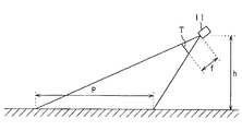
- FIG. 3 is a diagram showing a perspective transformation method.
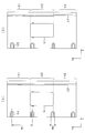
- 4 (a) and 4 (b) are diagrams showing a vehicle periphery image
- FIG. 5 is a diagram illustrating an overlapping area of the front past image and the back past image
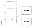
- FIG. 6 is a diagram showing a deviation calculation method.
- FIG. 7 is a diagram showing intermediate region images before and after correction
- FIG. 8 is a diagram showing a vehicle periphery image after correction
- FIG. 1 is a configuration diagram of an image display system according to an embodiment of the present disclosure.
- FIG. 2 is a diagram showing a camera and its shooting range.
- FIG. 3 is a diagram showing a perspective transformation method.
- 4 (a) and 4 (b) are diagrams showing a vehicle periphery image
- FIG. 5 is a diagram illustrating an overlapping area of
- FIG. 9 is a flowchart showing image creation processing.
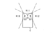
- FIG. 10 is a diagram showing a camera and its photographing range in the first modified example
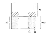
- FIG. 11 is a diagram showing a vehicle periphery image in the first modified example.
- FIG. 12 is a diagram showing a camera and its photographing range in the second modified example
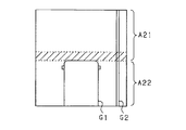
- FIG. 13 is a diagram showing a vehicle periphery image in the second modification example.
- FIG. 14 is a flowchart showing a deviation calculation process based on the periodicity of feature points.
- the present image display system includes a front camera 11 and a rear camera 12 as photographing units, an image processing unit 13 to which photographing data of the cameras 11 and 12 are input, and an image processing unit 13. And an in-vehicle monitor 14 as a display unit for displaying the created display image.
- the front camera 11 and the rear camera 12 are attached to the front side and the rear side of the vehicle, respectively.
- a predetermined range in front of the vehicle is photographed by the front camera 11, and a predetermined range in the rear of the vehicle is photographed by the rear camera 12.
- Each of these cameras 11 and 12 is a wide-angle camera capable of photographing in a wide-angle range.
- the cameras 11 and 12 can photograph at a viewing angle of 180 degrees in the front and rear of the vehicle.
- Each of the cameras 11 and 12 is a digital imaging system camera that performs imaging using a CCD image sensor or a CMOS image sensor.
- the front camera 11 is attached to the front side portion of the roof portion
- the rear camera 12 is attached to the rear side portion of the roof portion.
- the front camera 11 captures the front range R1
- the rear camera 12 captures the rear range R2.
- the front range R1 and the rear range R2 are arranged in front of and behind the vehicle C. For this reason, when the vehicle C moves forward, the range shot as the front range R1 by the front camera 11 is shot as the rear range R2 by the rear camera 12 as the vehicle C moves forward. Further, when the vehicle C moves backward, the range shot as the rear range R2 by the rear camera 12 is shot as the front range R1 by the front camera 11 as the vehicle C moves backward.
- both the front camera 11 and the rear camera 12 are arranged on the same line (on the center line X1) extending in the front-rear direction of the vehicle C, and photograph the front and rear of the vehicle with the center line X1 as the photographing center. .
- the front camera 11 cannot shoot the rear side of the vehicle, and the rear camera 12 cannot shoot the front side of the vehicle. Therefore, the left and right side portions of the vehicle C are in a range R3 (intermediate region) that is out of the field of view of both cameras 11 and 12.
- each camera 11, 12 shoots in front of the vehicle and behind the vehicle in a downward direction from the horizontal direction, so that the ground surface can be photographed. Therefore, the images taken by the cameras 11 and 12 include marking images such as white lines on the ground plane (on the road surface).
- the in-vehicle monitor 14 is provided in a position that can be visually recognized by the user while driving, for example, in the instrument panel.
- the shape and size of the in-vehicle monitor 14 may be arbitrary, in the present embodiment, since the vehicle peripheral image is displayed on the in-vehicle monitor 14 in a range including both the front and rear regions around the host vehicle, A vertically long display area is set on the display screen (see FIGS. 4A and 4B).
- the vehicle monitor 14 can display information other than the vehicle periphery image. When the vehicle periphery image is not displayed on the vehicle monitor 14, the vehicle front image (for example, darkness in front of the vehicle) is displayed on the display screen. Visual information) and various information other than the captured image may be displayed.
- the image processing unit 13 is an image processing device that creates a display image by combining the shooting data of the cameras 11 and 12 and displays the display image on the in-vehicle monitor 14.
- the display image created based on the shooting data of each camera 11 and 12 and displayed on the in-vehicle monitor 14 is also referred to as a composite image.
- the image processing unit 13 includes a first conversion circuit 21 that inputs the shooting data of the front camera 11 and a second conversion circuit 22 that inputs the shooting data of the rear camera 12. Performs perspective transformation on the respective shooting data of the front camera 11 and the rear camera 12 to create a bird's-eye view image.
- the bird's-eye view image is a bird's-eye view image in a state in which the shooting range of each camera 11, 12 is looked down vertically from the sky position.
- a front bird's-eye image and a rear bird's-eye image are created by the conversion circuits 21 and 22, respectively.
- Each of the cameras 11 and 12 captures the front of the vehicle and the rear of the vehicle at every predetermined time. According to each of the conversion circuits 21 and 22, the bird's-eye image at the front of the vehicle and the bird's-eye image at the rear of the vehicle at each predetermined time. Can be obtained.
- the image data of the bird's-eye view image created by the conversion circuits 21 and 22 is input to the CPU 23.
- the CPU 23 creates a vehicle peripheral image based on the front bird's-eye image and the rear bird's-eye image. This vehicle peripheral image is created as a bird's-eye view image, similar to the image after conversion by the conversion circuits 21 and 22.
- the range R3 outside the camera field of view is included in the vicinity (side of the vehicle) of the host vehicle, and therefore, the range R3 outside the camera field of view is taken by the front camera 11 (front bird's-eye view image). ) And any past image of the image captured by the rear camera 12 (rear bird's-eye view image).
- the image processing unit 13 has an image memory 24 for storing past images as a configuration for creating a vehicle peripheral image using past images.
- the vehicle C includes a vehicle speed sensor 16 that detects the vehicle speed, and a yaw rate sensor 17 that detects a yaw rate (a change speed of the rotation angle in the turning direction).
- the detection signals of the vehicle speed sensor 16 and the yaw rate sensor 17 are sequentially input to the CPU 23.
- the CPU 23 calculates the vehicle speed and yaw rate that are the running state of the vehicle based on the detection signals of the sensors 16 and 17. In this case, what is necessary is that the traveling state of the vehicle at the time of photographing with the cameras 11 and 12 can be grasped, and the moving distance and rotation angle of the vehicle C or the position and orientation of the vehicle C may be calculated. Further, the CPU 23 stores the past image of the front bird's-eye image and the past image of the rear bird's-eye image in association with the traveling information (vehicle speed and yaw rate) of the vehicle C at the time of image shooting in the image memory 24 at predetermined time intervals. .
- a photographed image (forward past image) photographed in the past by the front camera 11 is taken from the image memory 24 as an image in the range R3 outside the camera field of view. Read out. Then, a vehicle peripheral image is created from the current captured images (front current image and rear current image) by the cameras 11 and 12 and the past past image. If the vehicle is moving backward, a captured image (rear past image) captured in the past by the rear camera 12 is read from the image memory 24 as an image in the range R3 outside the camera field of view. Then, a vehicle peripheral image is created from the current captured image (front current image and rear current image) by the cameras 11 and 12 and the rear past image.
- the CPU 23 arranges and connects the front current image, the rear current image, and the front past image (or the back past image) side by side in the vehicle front-rear direction on the same plane.
- the past image is translated and rotated (Euclidean). Conversion), and each image is synthesized as one image.
- FIGS. 4 (a) and 4 (b) are diagrams showing a vehicle periphery image displayed on the display screen of the in-vehicle monitor 14.
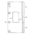
- FIG. In the same display screen, a front display area A1, a rear display area A2, and an intermediate display area A3 are defined. A front current image captured by the front camera 11 is displayed in the front display area A1, and a rear display is performed. In the area A2, the rear current image captured by the rear camera 12 is displayed, and in the intermediate display area A3, either the front past image or the rear past image is displayed.
- FIG. 4A and FIG. 4B it is assumed that the vehicle is moving forward, and a forward past image is displayed in the intermediate display area A3.
- the vehicle traveling direction is the y direction
- the direction orthogonal thereto is the x direction (the same applies to FIG. 5 described later).
- the length dimensions in the y direction of the display areas A1 to A3 may all be the same or different. Only the intermediate display region A3 may have a configuration in which the length dimension in the y direction is shorter than the other regions.
- the host vehicle image G1 is displayed at the center position of the display screen.
- the host vehicle image G1 is displayed at a position overlapping the forward past image (or the backward past image).
- the user can easily grasp the surrounding situation (relative positional relationship) with reference to the host vehicle.
- markings such as white lines drawn on the road surface are shown as information of the captured image.
- a straight line image G2 extending in the vehicle traveling direction is displayed on the right side of the vehicle, and a lane line image G3 attached to each parking section is displayed on the left side of the vehicle. It is displayed.
- the straight line image G2 is connected in a straight line in the vehicle traveling direction as shown in FIG. 4A. It will be.
- the lane line image G3 the interval between adjacent lane line images G3, that is, the width W1 of the parking space is uniform, and the lane line image G3 has a width in the arrangement direction of the plurality of parking spaces. In this case, the width W2 becomes uniform.
- Such a shift in the image joining portion is likely to occur at a portion where the images captured by different cameras are joined together. That is, when the vehicle C moves forward, a shift is likely to occur at the connecting portion between the rear current image displayed in the rear display area A2 and the front past image displayed in the intermediate display area A3. A shift is likely to occur at a joint portion between the front current image displayed in the display area A1 and the rear past image displayed in the intermediate display area A3.
- FIG. 4B shows a state in which there is a shift in the joined portion between the current rear image displayed in the rear display area A2 and the previous past image displayed in the intermediate display area A3. That is, in FIG. 4B, a deviation in the x direction occurs with respect to the straight line image G2. Further, the lane line image G3 is shifted in the y direction, and as a result, only the lane line image G3 in the image joining portion is crushed in the y direction compared to the other lane line images G3 (W2 is small). It has become).
- a vehicle peripheral image is appropriately created by calculating a shift in the joining portion of each image and correcting the image based on the shift.
- an overlapping region in which the rear current image and the front past image are overlapped and overlapped is set at the boundary portion of A3.
- the length dimension in the y direction of the forward past image is larger than the length dimension in the y direction of the intermediate display area A3, and the forward past image is displayed in the intermediate display area A3.
- an overlapping area Ap is defined at the boundary with the intermediate display area A3, and the front past image and the rear current image are overlapped in the overlapping area Ap.
- the CPU 23 extracts feature points for two images superimposed on each other in the overlapping area Ap, and compares the feature points of the same form to calculate the shift between the images. For example, a marking image on the road surface is extracted as a feature point, and a feature amount such as a luminance distribution around the feature point is compared to calculate a shift between the images.
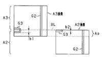
- FIG. 6 shows a backward current image displayed in the backward display area A2 and a forward past image displayed in the intermediate display area A3.
- A2 image and “A3 image”.
- the shifts in the x direction and the y direction are calculated by comparing the images in the overlapping portion in the overlapping region Ap. In this case, if the straight line image G2 as the feature point is shifted in the x direction in a state where the A2 image and the A3 image are superimposed, the shift amount is calculated as a shift in the x direction.
- the lengths b1 and b2 in the y direction of the partition line image G3 as feature points are calculated with reference to the boundary line BL between the rear display area A2 and the intermediate display area A3. , B2 to calculate the displacement in the y direction.
- an overlapping area Ap is set at the boundary between the front display area A1 and the intermediate display area A3, and in the overlapping area Ap, the overlapping area between the front current image and the rear past image A shift between images is calculated.
- the CPU 23 calculates a correction parameter for a past image (front past image or rear past image) as a correction target based on the shift between the images in the overlapping area Ap, and uses the correction parameter to calculate the past parameter. Perform correction by perspective transformation.
- perspective transformation is performed so that the past image is expanded and contracted in the x direction.
- perspective transformation is performed so that the past image is expanded and contracted in the y direction.
- the overlapping area Ap is set only at one end of the intermediate display area A3 in the y direction, and the past image in the intermediate display area A3 is based on the shift on the overlapping area Ap side.
- the whole of is to be corrected.
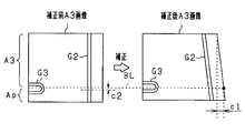
- the boundary line BL is expanded or contracted by c1 (expanded in FIG. 7).
- a correction in the y direction it is expanded or contracted by c2 on the boundary line BL (contracted in FIG. 7).
- the straight line image G2 in the corrected A3 image is converted so as to form an acute angle with the y direction, and the straight line image G2 in the A1 image and the straight line image G2 in the A2 image are converted. Tied. That is, the shift between the straight line image G2 in the A3 image and the straight line image G2 in the A2 image is eliminated while maintaining the connection between the straight line image G2 in the A1 image and the straight line image G2 in the A2 image. Further, compared to before correction (FIG. 4B), on the boundary line BL between the rear display area A2 and the intermediate display area A3, the lane marking image G3 in the A3 image is moved forward by c2 in the vehicle direction. .
- the position of the lane line image G3 in the corrected A3 image and the position of the lane line image G3 in the rear display area A2 are equal with respect to the boundary line BL between the rear display area A2 and the intermediate display area A3. Therefore, the distortion of the partition line image G3 at the boundary line BL is eliminated.
- the displacement of the white line or the like in the vehicle peripheral image displayed on the in-vehicle monitor 14 can be an obstacle when the host vehicle is traveling at a relatively low speed. Specifically, the vehicle is traveling in a parking lot. It is assumed that When traveling in a parking lot, it may be considered that the user often pays attention to markings on the road surface in order to park the vehicle in a desired parking section. Therefore, in the present embodiment, when the vehicle is traveling at a predetermined low speed, a vehicle peripheral image that is a bird's-eye view image is displayed on the in-vehicle monitor 14.
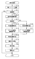
- FIG. 9 shows a flowchart of the image creation process in the present embodiment. This image creation process is performed at predetermined intervals by the CPU 23 of the image processing unit 13.
- step S10 the vehicle speed and yaw rate of the host vehicle are acquired.
- step S11 it is determined whether or not the host vehicle is in a predetermined low-speed traveling state. Specifically, it is determined whether or not the current vehicle speed is a predetermined value (for example, 30 km / h) or less.
- step S11 it may be determined whether or not the vehicle is currently traveling in the parking lot from information on the navigation device or the like. If step S11 is NO, the process ends. When step S11 is denied, information images other than vehicle periphery images, such as navigation information and a driving
- the image processing unit 13 may acquire the position of the vehicle from a GPS sensor mounted on the vehicle and determine that the vehicle is about to be parked.
- step S11 the process proceeds to step S12, and the bird's-eye view images (front current image and rear current image) after being converted by the first conversion circuit 21 and the second conversion circuit 22 are acquired.
- the front current image and the rear current image are temporarily stored in the working memory, and are also stored in the image memory 24 as history images.
- the storage in the image memory 24 is performed in association with the vehicle running state such as the vehicle speed and yaw rate at that time.
- the history image stored in the image memory 24 is also referred to as a past image.
- step S13 it is determined whether or not the host vehicle is in a forward traveling state. This determination is performed based on, for example, the shift position of the vehicle transmission. If the host vehicle is in the forward state, the process proceeds to step S14, and if the host vehicle is in the reverse state, the process proceeds to step S16.
- step S14 the forward past image is read from the image memory 24 as an image to be displayed in the intermediate display area A3. In this case, a plurality of forward past images are stored in the image memory 24 in chronological order, and a target image to be used for the current image generation may be determined based on the vehicle speed.
- step S15 an overlapping area Ap is set at the boundary between the rear display area A2 and the intermediate display area A3.
- step S16 the backward past image is read from the image memory 24 as an image to be displayed in the intermediate display area A3.
- a plurality of rear past images are stored in time series in the image memory 24, and an image to be used this time may be determined based on the vehicle speed.
- step S17 an overlapping area Ap is set at the boundary between the front display area A1 and the intermediate display area A3.
- step S18 the forward current image and backward current image acquired in step S11 and the forward past image or backward past image acquired in either step S14 or S16 are arranged on the same plane and synthesized as one image. By doing so, a vehicle periphery image is created. At this time, synthesis (joining) of the images is performed based on the vehicle travel information at the time of capturing the past image and the current vehicle travel state.
- step S19 a shift between images in the overlapping area Ap is calculated.
- step S20 the vehicle periphery image is corrected based on the shift between the images. At this time, image correction is performed on the past image displayed in the intermediate display area A3.
- step S21 the corrected vehicle periphery image is output to the in-vehicle monitor 14, and the process is terminated.
- the processes from S13 to S18 function as an image creation unit
- the process in S19 functions as a deviation calculation unit
- the process in S20 functions as a correction unit.
- the process of S21 functions as a display control part.
- each of the above parts is classified for convenience by focusing on the function of the vehicular image processing apparatus, and it is not necessary that the interior of the vehicular image processing apparatus is physically divided into seven parts.
- Each of the above sections can be realized by hardware using a logic circuit or CPU, or can be realized by software as a computer program or a part of a program.
- a plurality of photographed images photographed by the cameras 11 and 12 are connected to create a display image, and the created image is displayed on the in-vehicle monitor 14. Thereby, the image showing the range wider than the range image
- FIG. for example, if the installation positions of the cameras 11 and 12 are deviated from the initial positions, a deviation occurs between the two images when the images are joined. Therefore, the shift between the images in the joined portion is calculated. Specifically, the shift between the images is calculated in at least one of the joined portion of the front current image and the intermediate region image and the joined portion of the rear current image and the intermediate region image. Then, the display image is corrected based on the calculated deviation. Thereby, it becomes possible to display a display image on the vehicle-mounted monitor 14 suitably.
- the images are overlapped in the overlapping area Ap, and the shift between the images in the overlapping area Ap is calculated.
- an overlapping area Ap is set at the boundary between the display areas A2 and A3.
- an overlapping area is set at the boundary between the display areas A1 and A3. Ap is set. Accordingly, in the configuration in which the three images are combined as the vehicle peripheral image, the shift can be calculated and corrected at a portion where the shift between the images is likely to occur. In this case, it is possible to suppress an excessive increase in calculation load due to deviation calculation and correction.
- Sense of discomfort given to the user can be reduced by adopting a configuration in which the entire image is targeted for correction.
- the correction is performed for the end portion that is not the detection target of the shift, the correction causes a shift between the images. Therefore, by performing correction so that the end portion that is not the detection target of the shift is not changed while the entire image is set as the correction target, it is possible to eliminate the disadvantage that shift is caused by the correction.
- the overlapping area Ap is set only at one end of the intermediate display area A3 in the y direction, and the past image in the intermediate display area A3 is corrected based on the shift on the overlapping area Ap side.
- this may be changed as follows.
- Overlap areas Ap are set at both ends in the y direction of the intermediate display area A3, and the past image of the intermediate display area A3 is corrected based on the shift on the overlap area Ap side. That is, for example, when the vehicle is moving forward, a deviation between the front current image and the front past image is calculated, a deviation between the front past image and the rear current image is calculated, and the front past image is corrected based on both of the deviations.
- the vehicle peripheral image is created by using a plurality of photographing units (the front camera 11 and the rear camera 12) and combining the current image and the past image. You may change like a 1st modification and a 2nd modification.
- a vehicle peripheral image is created by combining a plurality of current images photographed by a plurality of photographing units.
- the past image is not used.
- the vehicle is provided with a first camera 31 for front-side shooting, a second camera 32 for right-side shooting, and a third camera 33 for left-side shooting.
- the captured images of these cameras 31 to 33 are input to the image processing unit 13.
- the image conversion processing in the image processing unit 13 is the same as described above.
- the photographing ranges of the cameras 31 to 33 are a front range R11, a right side range R12, and a left side range R13, respectively.
- the front range R11 and the right side range R12 partially overlap, and the front range R11 and the left side range R13. And are partially overlapping.
- the viewing angle of each camera is smaller than 180 degrees, but the angle is arbitrary, and the viewing angle may be 180 degrees as in FIG.
- FIG. 11 is a diagram showing a vehicle periphery image displayed on the display screen of the in-vehicle monitor 14.
- a vehicle peripheral image of a portion excluding the rear of the host vehicle image G1 is displayed.
- a front display area A11, a right side display area A12, and a left side display area A13 are defined around the host vehicle image G1, and the first to third cameras 31 to 33 are defined in each display area.
- the currently captured image is displayed.
- the left and right side display areas A12 and A13 are shaded.
- the CPU 23 calculates a shift between the images in the overlapping region of the images and corrects any image based on the shift.
- the correction by the perspective transformation may be performed with the display image of the right side display area A12 and the display image of the left side display area A13 as correction targets.
- a configuration in which a plurality of current images captured by a plurality of cameras are combined to create a vehicle peripheral image includes a front camera and a right-side camera (or a left-side camera).
- a configuration in which two captured images are combined, and a configuration in which the captured images of the front and rear and left and right four cameras are combined are conceivable.
- a vehicle peripheral image is created by synthesizing a current image and a past image taken by one photographing unit.
- a front camera 41 for front photographing is provided in the vehicle.
- the captured image of the front camera 41 is input to the image processing unit 13.
- the image conversion processing in the image processing unit 13 is the same as described above.
- the imaging range R21 of the front camera 41 may be the same as, for example, the front range R1 shown in FIG.
- the captured image in front of the vehicle is sequentially stored in the image memory as a past image in association with the vehicle running state (similar to the configuration in FIG. 1).
- FIG. 13 is a diagram showing a vehicle periphery image displayed on the display screen of the in-vehicle monitor 14.
- a front display area A21 is defined at a position in front of the host vehicle image G1
- a side display area A22 is defined at a position beside the host vehicle image G1, and each of these displays is displayed.
- the current image and the past image are displayed in the area.
- the CPU 23 joins the current image and the past image in a partially overlapping state at the boundary portion between the display regions A21 and A22, and calculates the shift between the images in the overlapping region (hatched portion in the figure).
- one of the images is corrected based on the deviation.
- correction for example, correction by perspective transformation may be performed with a past image as a correction target.
- the vehicle peripheral image is created using one current image and one past image, but in addition to this, one current image and two (or more) past images. It is good also as a structure which produces a vehicle periphery image using. In this case, it is preferable to use a past image to create an image behind the vehicle. Regarding the correction of the image, it is preferable to calculate a deviation for a joined portion of past images and perform a correction for eliminating the deviation.
- the shift is calculated by comparing the feature points of the image in the overlapping area Ap, and the correction is performed based on the calculated shift amount.
- FIG. 14 shows a flow chart of a shift calculation process based on the periodicity of feature points. This process is performed by the image processing unit 13 in step S19 in the image creation process shown in FIG.
- step S30 whether or not the display image that displays the periphery of the vehicle includes a plurality of images (repeated images) that have the same shape and size and are arranged side by side in the vehicle traveling direction. Determine whether. If the display image includes a repeated image (S30: YES), at step S31, at least one of the shape and size of the subject to be photographed at the joining portion between the images is other than the joining portion. It is determined whether or not the shape and size of the shooting target are different. If it is determined that there is a difference in the shape and size of the shooting target in the joint portion (S31: YES), in step S32, a deviation is calculated based on the difference in the shape and size of the shooting target. To finish the process.
- the display image includes a repeated image (S30: YES)
- step S31 at step S31, at least one of the shape and size of the subject to be photographed at the joining portion between the images is other than the joining portion. It is determined whether or not the shape and size of the shooting target are
- photographing objects having the same shape and size may repeatedly appear at predetermined intervals along the vehicle traveling direction.
- the display image (bird's-eye view image) including such an imaging target it is possible to suppress the inconvenience that the shape and size are different between the front side in the vehicle traveling direction and the rear side.
- -It is good also as a structure provided with the means to determine which is made into correction object about several images. For example, when vehicle vibration exceeding a predetermined level occurs during acquisition of any one of a plurality of captured images used for creating a display image, there is a high possibility that an error has occurred for that image. The image is targeted for correction.
- the past image is corrected based on the shift in the overlapping portion between the images, but the present image may be corrected. Moreover, it is good also as a structure which correct
- the image may be corrected when the yaw rate detected by the yaw rate sensor 17 is greater than a predetermined value.
- the larger the yaw rate the more likely the difference between the actual value and the calculated value of the vehicle position and the more likely the displacement between the images, so that the image can be corrected appropriately.
- the position and orientation of the vehicle may be obtained from a GPS sensor or a digital compass, respectively.
Landscapes
- Engineering & Computer Science (AREA)
- Multimedia (AREA)
- Physics & Mathematics (AREA)
- General Physics & Mathematics (AREA)
- Theoretical Computer Science (AREA)
- Mechanical Engineering (AREA)
- Closed-Circuit Television Systems (AREA)
- Image Processing (AREA)
- Image Analysis (AREA)
Abstract
車両用画像処理装置は、車両に適用され、該車両に搭載され、撮影部(11,12)、表示部(14)、画像作成部、ずれ算出部、補正部と表示制御部を備える。撮影部は、車両の周辺の所定範囲を撮影する。表示部は、撮影部により撮影された複数の撮影画像に基づいて作成された表示画像を表示する。画像作成部は、撮影部により撮影された複数の撮影画像を繋ぎ合わせることにより、表示部で表示させるための表示画像を作成する。ずれ算出部は、表示画像の作成に際し、表示画像における複数の撮影画像の繋ぎ合わせ部分の画像同士のずれを算出する。補正部は、ずれに基づいて表示画像を補正する。表示制御部は、補正後の表示画像を表示部に表示させる。
Description
本開示は、2013年4月15日に出願された日本出願番号2013-084843号に基づくもので、ここにその記載内容を援用する。
本開示は、車両周辺について撮影された画像を表示装置に表示する車両用画像処理装置に関するものである。
車両周囲の状況を車載カメラで撮影するとともに、その車載カメラで撮影した複数の画像を合成し、その合成後の画像を表示装置に表示する技術が知られている。例えば、車両の前方カメラにより撮影した前方画像と、後方カメラにより撮影した後方画像とを合成して合成画像として鳥瞰画像を作成し、その鳥瞰画像を表示装置に表示させるようにした車両用画像処理装置が知られている(例えば特許文献1)。
複数の画像を合成して1つの鳥瞰画像を作成する場合、画像同士の繋ぎ合わせ部分においてずれが生じることが考えられ、そのずれが生じると、表示画像を見たユーザが違和感を覚えたり、同ユーザに路面上の白線の位置などの情報が正しく伝わらなかったりすることが懸念される。画像同士のずれが生じる原因としては、カメラの設置位置や設置方向が画像処理装置側の認識と異なっていることや、複数の画像の属性情報(撮影時の車速等)に誤りがあることで繋ぎ合わせに不備が生じていることなどが考えられる。
本開示は、上記課題に鑑みてなされたものであり、撮影部によって撮影された複数の画像を好適に繋ぎ合わせて画像を作成することが可能な車両用画像処理装置を提供することを目的とする。
本開示の一態様による車両用画像処理装置は、車両に適用され、該車両に搭載され、撮影部、表示部、画像作成部、ずれ算出部、補正部と表示制御部を備える。撮影部は、車両の周辺の所定範囲を撮影する。表示部は、撮影部により撮影された複数の撮影画像に基づいて作成された表示画像を表示する。画像作成部は、撮影部により撮影された複数の撮影画像を繋ぎ合わせることにより、表示部で表示させるための表示画像を作成する。ずれ算出部は、表示画像の作成に際し、表示画像における複数の撮影画像の繋ぎ合わせ部分の画像同士のずれを算出する。補正部は、ずれに基づいて表示画像を補正する。表示制御部は、補正後の表示画像を表示部に表示させる。
上記装置によると、撮影部によって撮影された複数の画像を好適に繋ぎ合わせて画像を作成することが可能である。
本開示についての上記目的およびその他の目的、特徴や利点は、添付の図面を参照しながら下記の詳細な記述により、より明確になる。その図面は、
図1は、本開示の一実施形態による画像表示システムの構成図であり、
図2は、カメラとその撮影範囲を示す図であり、
図3は、透視変換の方法を示す図であり、
図4(a)と図4(b)は、車両周辺画像を示す図であり、
図5は、前方過去画像と後方過去画像の重複領域を示す図であり、
図6は、ずれ算出方法を示す図であり、
図7は、補正の前後における中間領域画像を示す図であり、
図8は、補正後の車両周辺画像を示す図であり、
図9は、画像作成処理を示すフロー図であり、
図10は、第1変形例におけるカメラとその撮影範囲を示す図であり、
図11は、第1変形例における車両周辺画像を示す図であり、
図12は、第2変形例におけるカメラとその撮影範囲を示す図であり、
図13は、第2変形例における車両周辺画像を示す図であり、
図14は、特徴点の周期性に基づくずれ算出処理を示すフロー図である。
以下、車両用画像処理装置としての画像処理ユニットを車両(自動車)の画像表示システムに適用した一実施形態について、図面を参照しつつ説明する。
図1に示すように、本画像表示システムは、撮影部としての前方カメラ11及び後方カメラ12と、それら各カメラ11,12の撮影データが入力される画像処理ユニット13と、画像処理ユニット13により作成された表示用画像を表示する表示部としての車載モニタ14とを有している。
前方カメラ11及び後方カメラ12は、車両の前側及び後側にそれぞれ取り付けられており、前方カメラ11により車両前方の所定範囲が撮影され、後方カメラ12により車両後方の所定範囲が撮影される。これら各カメラ11,12は、広角範囲での撮影が可能な広角カメラであり、例えば車両前方及び車両後方において180度の視野角で撮影可能となっている。各カメラ11,12は、CCDイメージセンサやCMOSイメージセンサによる撮影を行うデジタル撮影方式のカメラである。
より具体的には、図2に示すように、車両Cには、例えばルーフ部分の前側部に前方カメラ11が取り付けられるとともに、ルーフ部分の後側部に後方カメラ12が取り付けられている。そして、前方カメラ11は前方範囲R1を撮影し、後方カメラ12は後方範囲R2を撮影する。前方範囲R1と後方範囲R2とは車両Cの前方及び後方に並んでいる。このため、車両Cが前進する場合には、前方カメラ11によって前方範囲R1として撮影された範囲が、車両Cの前進に伴い、後方カメラ12によって後方範囲R2として撮影される。また、車両Cが後退する場合には、後方カメラ12によって後方範囲R2として撮影された範囲が、車両Cの後退に伴い、前方カメラ11によって前方範囲R1として撮影される。なお、前方カメラ11及び後方カメラ12は、いずれも車両Cの前後方向に延びる同一線上(中心線X1上)に配置されており、その中心線X1を撮影中心として車両前方及び車両後方を撮影する。
前方カメラ11はそれよりも車両後方側の撮影が不可であり、後方カメラ12はそれよりも車両前方側の撮影が不可である。そのため、車両Cの左右の側方部は、両カメラ11,12の視野外となる範囲R3(中間領域)となっている。
また、各カメラ11,12は、水平方向よりも下向きで車両前方、車両後方をそれぞれ撮影し、地上面の撮影が可能になっている。したがって、各カメラ11,12により撮影された画像には、地上平面上(路面上)における白線等のマーキング画像が含まれるようになっている。
図1の説明に戻り、車載モニタ14は、車室内においてユーザが運転中に視認可能な位置、例えばインパネ部に設けられている。車載モニタ14の形状及び大きさは任意でよいが、本実施形態では、自車両を中心としてその前後両方の領域を含む範囲で車両周辺画像を車載モニタ14に表示することから、車載モニタ14の表示画面に縦長の表示エリアが設定されている(図4(a)と図4(b)参照)。なお、車載モニタ14には、車両周辺画像以外の情報を表示することが可能であり、車載モニタ14に車両周辺画像を表示しない場合には、その表示画面に車両前方画像(例えば車両前方の暗視画像)や、撮影画像以外の各種情報が表示されるとよい。
画像処理ユニット13は、各カメラ11,12の撮影データを合成して表示用画像を作成し、その表示用画像を車載モニタ14に表示させる画像処理装置である。各カメラ11,12の撮影データに基づいて作成され、車載モニタ14に表示される表示用画像は、合成画像とも称する。画像処理ユニット13は、前方カメラ11の撮影データを入力する第1変換回路21と、後方カメラ12の撮影データを入力する第2変換回路22とを有しており、これら各変換回路21,22は、前方カメラ11及び後方カメラ12の各撮影データについてそれぞれ透視変換を行い、鳥瞰画像を作成する。鳥瞰画像は、各カメラ11,12の撮影範囲を上空位置から鉛直方向に見下ろした状態の俯瞰画像である。各変換回路21,22により、それぞれ前方鳥瞰画像、後方鳥瞰画像が作成される。
各カメラ11,12は、所定時間ごとに車両前方及び車両後方をそれぞれ撮影するものであり、各変換回路21,22によれば、所定時間ごとに車両前方の鳥瞰画像と車両後方の鳥瞰画像とが得られるようになっている。
各変換回路21,22における透視変換について補足の説明をする。図3に示すように、地上面から高さhの位置に設けられた前方カメラ11で地上面を撮影する場合、撮影画像として、カメラ位置から所定の焦点距離fにあるスクリーン平面T上の撮影画像が得られる。この場合、前方カメラ11が地上平面を撮影することは、地上平面座標からスクリーン平面T上の二次元座標への透視変換が実行されることと等しい。そこで、各変換回路21,22では、各カメラ11,12によって撮影された撮影画像に対して、上記透視変換と逆の透視変換を行うことで、スクリーン平面T上の座標から地上平面上の座標への変換を行い、それにより地上面上の画像である鳥瞰画像(図3のPの範囲の平面画像)を作成する。
各変換回路21,22により作成された鳥瞰画像の画像データはCPU23に入力される。CPU23は、前方鳥瞰画像と後方鳥瞰画像とに基づいて車両周辺画像を作成する。この車両周辺画像は、各変換回路21,22での変換後の画像と同様、鳥瞰画像として作成される。
本実施形態の画像表示システムでは、自車両の周辺(車両側方)にカメラ視野外の範囲R3が含まれるため、そのカメラ視野外の範囲R3については、前方カメラ11の撮影画像(前方鳥瞰画像)、及び後方カメラ12の撮影画像(後方鳥瞰画像)のいずれかの過去画像を用いることとしている。そして、過去画像を用いて車両周辺画像を作成するための構成として、画像処理ユニット13は、過去画像を記憶する画像メモリ24を有している。また、車両Cは、車速を検出する車速センサ16と、ヨーレイト(旋回方向への回転角の変化速度)を検出するヨーレイトセンサ17とを備えている。
車速センサ16及びヨーレイトセンサ17の検出信号はCPU23に逐次入力される。CPU23は、これら各センサ16,17の検出信号に基づいて、車両の走行状態である車速及びヨーレイトを算出する。このとき要は、各カメラ11,12での撮影時における車両の走行状態が把握できればよく、車両Cの移動距離及び回転角、或いは車両Cの位置及び向きが算出されればよい。また、CPU23は、所定時間ごとに、前方鳥瞰画像の過去画像と後方鳥瞰画像の過去画像とを、画像撮影時の車両Cの走行情報(車速やヨーレイト)に対応付けて画像メモリ24に記憶する。
車両周辺画像を作成する場合に、車両が前進しているのであれば、カメラ視野外の範囲R3の画像として、前方カメラ11により過去に撮影された撮影画像(前方過去画像)が画像メモリ24から読み出される。そして、各カメラ11,12による今現在の撮影画像(前方現在画像及び後方現在画像)と前方過去画像とにより車両周辺画像が作成される。また、車両が後退しているのであれば、カメラ視野外の範囲R3の画像として、後方カメラ12により過去に撮影された撮影画像(後方過去画像)が画像メモリ24から読み出される。そして、各カメラ11,12による今現在の撮影画像(前方現在画像及び後方現在画像)と後方過去画像とにより車両周辺画像が作成される。
車両周辺画像の作成に際し、CPU23は、前方現在画像と後方現在画像と前方過去画像(又は後方過去画像)とを、同一平面上において車両前後方向に並べて配置し繋ぎ合わせる。このとき、今現在の車両Cの走行状態(車速やヨーレイト)と、過去画像が撮影された時の車両Cの走行状態(車速やヨーレイト)とに基づいて、過去画像の平行移動及び回転(ユークリッド変換)を行い、各画像を一画像として合成する。
図4(a)と図4(b)は、車載モニタ14の表示画面に表示される車両周辺画像を示す図である。同表示画面においては、前方表示領域A1と後方表示領域A2と中間表示領域A3とが定められており、前方表示領域A1には、前方カメラ11により撮影された前方現在画像が表示され、後方表示領域A2には、後方カメラ12により撮影された後方現在画像が表示され、中間表示領域A3には、前方過去画像及び後方過去画像のいずれかが表示される。図4(a)と図4(b)においては、車両の前進時が想定され、中間表示領域A3には前方過去画像が表示されている。説明の便宜上、図4(a)と図4(b)では、車両進行方向をy方向、それに直交する方向をx方向としている(後述の図5等も同様)。なお、各表示領域A1~A3のy方向の長さ寸法は全て同じであってもよいし、各々異なっていてもよい。中間表示領域A3だけが、他領域よりもy方向の長さ寸法が短い構成であってもよい。
中間表示領域A3には、表示画面の中央となる位置に自車両画像G1が表示されている。この自車両画像G1は、前方過去画像(又は後方過去画像)に重複する位置に表示されている。車両周辺画像中に自車両画像G1が表示されることで、ユーザが自車両を基準として周囲の状況(相対的な位置関係)を把握しやすくなるようになっている。また、図4(a)と図4(b)の車両周辺画像には、撮影画像の情報として、路面上に引かれた白線等のマーキングが示されている。ここでは、車両Cが駐車場を走行する場合を想定しており、車両右側には車両走行方向に延びる直線画像G2が表示され、車両左側には駐車区画ごとに付された区画線画像G3が表示されている。
ここで、車載モニタ14の各表示領域A1~A3に各々表示される画像がずれなく適正に繋ぎ合わされていれば、図4(a)に示すように車両走行方向において直線画像G2が一直線に繋がることとなる。また、区画線画像G3については、隣合う区画線画像G3同士の間隔、すなわち駐車スペースの幅W1が均等になるとともに、区画線画像G3が複数の駐車スペースの並び方向に幅を有している場合に、その幅W2が均等になる。
しかしながら、各カメラ11,12の取り付けの状態や車両の走行状態によっては、各表示領域A1~A3における表示画像の繋ぎ合わせ部分でずれが生じることが考えられる。すなわち、各カメラ11,12の取り付け誤差に起因してカメラ撮影方向がずれていると、各変換回路21,22で変換した鳥瞰画像を繋ぎ合わせる際に、図4(a)と図4(b)のx方向及びy方向の少なくともいずれかでずれが生じる。また、車速センサ16やヨーレイトセンサ17で検出される車両走行状態が、実際の車両走行状態と異なっている場合には、過去画像の平行移動及び回転が適正に行われず、やはり画像繋ぎ合わせ部分でのずれが生じる。車両走行状態の検出誤差が生じる要因としては、車両挙動の過渡変化に正しく追従できないことや、タイヤのスリップにより車速が誤検出されること等が考えられる。
こうした画像繋ぎ合わせ部分におけるずれは、異なるカメラの撮影画像同士が繋ぎ合わされる部位で生じやすい。つまり、車両Cの前進時には、後方表示領域A2に表示される後方現在画像と、中間表示領域A3に表示される前方過去画像との繋ぎ合わせ部分でずれが生じやすく、車両Cの後退時には、前方表示領域A1に表示される前方現在画像と、中間表示領域A3に表示される後方過去画像との繋ぎ合わせ部分でずれが生じやすい。
図4(b)には、後方表示領域A2に表示される後方現在画像と、中間表示領域A3に表示される前方過去画像との繋ぎ合わせ部分でずれが生じている状態を示している。すなわち、図4(b)では、直線画像G2についてx方向のずれが生じている。また、区画線画像G3についてy方向のずれが生じており、その結果、画像繋ぎ合わせ部分における区画線画像G3だけが、他の区画線画像G3に比べてy方向に潰れた状態(W2が小さくなった状態)となっている。
そこで、本実施形態においては、各画像の繋ぎ合わせ部分におけるずれを算出するとともに、そのずれに基づいて画像の補正を行うことで、車両周辺画像を適正に作成するようにしている。
まずは、画像繋ぎ合わせ部分におけるずれ算出について説明する。なおここでは、車両Cの前進時を想定している。
車両の前進時には、上述したとおり後方表示領域A2に表示される後方現在画像と、中間表示領域A3に表示される前方過去画像との繋ぎ合わせ部分でずれが生じやすくなっており、その表示領域A2及びA3の境界部分に、後方現在画像と前方過去画像とが重複して重ね合わされる重複領域が設定される。具体的には、図5に示すように、前方過去画像のy方向の長さ寸法は、中間表示領域A3のy方向の長さ寸法よりも大きくなっており、前方過去画像を中間表示領域A3に配置すると、その前方過去画像の一部が後方表示領域A2に重ねられる。この場合、後方表示領域A2には、中間表示領域A3との境界部分に重複領域Apが定められており、その重複領域Apには前方過去画像と後方現在画像とが重複して配置される。
CPU23は、重複領域Apで互いに重ね合わされた2つの画像について特徴点を抽出し、同じ形態の特徴点同士を比較することで、画像同士のずれを算出する。例えば、路面上のマーキング画像を特徴点として抽出し、その特徴点周辺の輝度の分布などの特徴量を比較することで、画像同士のずれを算出する。
ずれ算出について図6を用いてより具体的に説明する。図6には、後方表示領域A2に表示される後方現在画像と、中間表示領域A3に表示される前方過去画像とを示しており、ここでは便宜上、それらを「A2画像」、「A3画像」と称する。A2画像及びA3画像では、重複領域Apでの重複部分において画像同士の比較によりx方向及びy方向のずれがそれぞれ算出される。この場合、A2画像及びA3画像を重ね合わせた状態で、特徴点としての直線画像G2がx方向にずれていれば、そのずれ分がx方向のずれとして算出される。
また、A2画像及びA3画像について、後方表示領域A2と中間表示領域A3との境界線BLを基準として、特徴点としての区画線画像G3のy方向長さb1,b2がそれぞれ算出され、それらb1,b2の比較により、y方向のずれが算出される。
なお、車両の後退時には、上記とは異なり、前方表示領域A1及び中間表示領域A3の境界部分に重複領域Apが設定され、その重複領域Apにおいて、前方現在画像と後方過去画像との重なり部分により画像同士のずれが算出される。
また、CPU23は、重複領域Apでの画像同士のずれに基づいて過去画像(前方過去画像又は後方過去画像)を補正対象として補正パラメータを算出し、その補正パラメータを用いて、過去画像に対して透視変換による補正を実施する。この場合、重複領域Apにおいて、現在画像の特徴点と過去画像の特徴点とがx方向にずれている場合は、そのx方向に過去画像を伸縮させるように透視変換を実施する。また、現在画像の特徴点と過去画像の特徴点とがy方向にずれている場合は、そのy方向に過去画像を伸縮させるように透視変換を実施する。
本実施形態では、中間表示領域A3のy方向の両端のうち一方の端部にのみ重複領域Apが設定されており、重複領域Ap側でのずれに基づいて、中間表示領域A3での過去画像の全体が補正されるようになっている。この場合、ずれが算出されていない側の端部については、画像が伸縮されないようにして補正が行われる。つまり、中間表示領域A3のy方向の両端のうち重複領域Ap側では補正量=最大、その反対側では補正量=0として、透視変換による補正が行われる。
具体的には、図7に示すように、重複領域Apでのx方向のずれがc1、y方向のずれがc2である場合に、重複領域Ap側でのx方向の補正量=c1、y方向の補正量=c2として、矩形状の補正前画像が台形状に透視変換される。この場合、特に、x方向の補正として、境界線BL上でc1分だけ伸縮(図7では伸張)される。また、y方向の補正として、境界線BL上でc2分だけ伸縮(図7では収縮)される。
図8に示すように、透視変換による補正に伴って、補正後A3画像における直線画像G2はy方向と鋭角を為すように変換され、A1画像における直線画像G2とA2画像における直線画像G2とが結ばれる。つまり、A1画像における直線画像G2とA2画像における直線画像G2の繋がりが保たれつつ、A3画像における直線画像G2とA2画像における直線画像G2とのずれが解消される。また、補正前(図4(b))と比較すると、後方表示領域A2と中間表示領域A3との境界線BL上において、A3画像における区画線画像G3は車両方向前方にc2だけ移動している。この移動に伴って、後方表示領域A2と中間表示領域A3との境界線BLを基準として、補正後A3画像における区画線画像G3の位置と後方表示領域A2における区画線画像G3の位置とが等しくなるため、境界線BLにおける区画線画像G3のゆがみが解消されている。
また、車載モニタ14に表示された車両周辺画像について白線等のずれが支障となり得るのは、自車両が比較的低い速度で走行している場合であり、具体的には駐車場内を走行している場合が想定される。駐車場での走行時には、所望の駐車区画内に自車両を駐車させるために、路面上のマーキングを注視することが多いとも考えられる。そこで本実施形態では、車両が所定の低速状態で走行している場合に、鳥瞰画像である車両周辺画像を車載モニタ14に表示させるようにしている。
本実施形態における画像作成処理のフローチャートを図9に示す。この画像作成処理は、画像処理ユニット13のCPU23によって所定周期ごとに実施される。
まずステップS10では、自車両の車速とヨーレイトとを取得する。続くステップS11では、自車両が所定の低速走行状態にあるか否かを判定する。具体的には、今現在の車速が所定値(例えば、30km/h)以下か否かを判定する。なお、ステップS11において、ナビゲーション装置の情報等から、今現在、駐車場内の走行中であるか否かを判定するようにしてもよい。そして、ステップS11がNOであれば、処理を終了する。ステップS11が否定される場合、車載モニタ14には、ナビゲーション情報や走行状態情報など、車両周辺画像以外の情報画像が表示される。
駐車時において、ユーザは白線などの目標物を基準にして車両を操作するため、画像にずれが生じていると車両と目標物との把握が困難になる。そこで、車両が駐車されようとしている場合に、画像の補正を行い補正後の画像を車載モニタ14に表示することで、ユーザに対して好適に情報を提示することが可能となる。なお、画像処理ユニット13が、車両に搭載されているGPSセンサから車両の位置を取得して、車両が駐車されようとしていると判定する構成としてもよい。
また、ステップS11がYESであればステップS12に進み、第1変換回路21及び第2変換回路22による変換後の鳥瞰画像(前方現在画像及び後方現在画像)を取得する。このとき、前方現在画像及び後方現在画像を、それぞれ作業用メモリに一時記憶するとともに、画像メモリ24に履歴画像として記憶する。画像メモリ24への記憶は、その時の車速やヨーレイトといった車両走行状態に対応付けた上で行われる。以下、画像メモリ24に記憶されている履歴画像は、過去画像とも称する。
その後、ステップS13では、自車両が前進状態にあるか否かを判定する。この判定は、例えば車両変速装置のシフト位置に基づいて実施される。自車両が前進状態にあればステップS14に進み、自車両が後退状態にあればステップS16に進む。ステップS14では、画像メモリ24から、中間表示領域A3に表示する画像として前方過去画像を読み出す。この場合、画像メモリ24には時系列で複数の前方過去画像が記憶されており、そのうちから今回の画像作成に使用する対象画像が車速に基づいて決定されるとよい。また、ステップS15では、後方表示領域A2と中間表示領域A3との境界部分に重複領域Apを設定する。
一方、ステップS16では、画像メモリ24から、中間表示領域A3に表示する画像として後方過去画像を読み出す。この場合、画像メモリ24には時系列で複数の後方過去画像が記憶されており、そのうちから今回使用する画像が車速に基づいて決定されるとよい。また、ステップS17では、前方表示領域A1と中間表示領域A3との境界部分に重複領域Apを設定する。
その後、ステップS18では、ステップS11で取得した前方現在画像及び後方現在画像と、ステップS14又はS16のいずれかで取得した前方過去画像又は後方過去画像とを同一平面上に配置して一画像として合成することで、車両周辺画像を作成する。このとき、過去画像の撮影時点の車両走行情報と今現在の車両走行状態とに基づいて、各画像の合成(繋ぎ合わせ)が実施される。
その後、ステップS19では、重複領域Apでの画像同士のずれを算出する。続くステップS20では、画像同士のずれに基づいて車両周辺画像の補正を実施する。このとき、中間表示領域A3に表示される過去画像を対象にして画像補正を実施する。ステップS21では、補正後の車両周辺画像を車載モニタ14に出力して処理を終了する。
上記画像処理ユニット13のCPU23により実行される画像作成処理において、S13からS18の処理が、画像作成部として機能し、S19の処理が、ずれ算出部として機能し、S20の処理が補正部として機能し、S21の処理が表示制御部として機能する。
尚、上記各部は、車両用画像処理装置の機能に着目して便宜的に分類したものであり、車両用画像処理装置の内部が物理的に7つの部分に区分されている必要はない。また、上記各部は、論理回路あるいはCPUなどを用いてハードウェア的に実現することもできるし、コンピュータープログラムあるいはプログラムの一部としてソフトウェア的に実現することもできる。
以下、本実施形態の効果について述べる。
カメラ11,12によって撮影された複数の撮影画像を繋ぎ合わせて表示画像を作成し、その作成された画像を車載モニタ14に表示する。これにより、一の画像として撮影された範囲より広い範囲を表す画像を車載モニタ14に表示することができる。ここで、例えば、カメラ11,12の設置位置などが初期位置からずれると、画像を繋ぎ合わせるときに二枚の画像間においてずれが生じる。そこで、繋ぎ合わせ部分の画像同士のずれを算出する。具体的には、前方現在画像及び中間領域画像の繋ぎ合わせ部分と、後方現在画像及び中間領域画像の繋ぎ合わせ部分との少なくともいずれかで画像同士のずれを算出する。そして、その算出されたずれに基づいて、表示画像を補正する。これにより、好適に表示画像を車載モニタ14に表示することが可能になる。
重複領域Apにおいて画像同士を重複させ、重複領域Apでの画像同士のずれを算出する。これにより、各画像の並び方向(y方向)及びそれに直交する方向(x方向)のいずれの方向についてもずれの算出を容易に実施できる。特に、各画像の並び方向(y方向)のずれについて算出することが容易になる。そして、その算出されたずれに基づいて補正を行うことで好適に画像同士を繋ぎ合わせることが可能になる。
複数のカメラ11,12による複数の撮影画像を繋ぎ合わせる場合に、カメラ11,12の取り付け誤差に起因してカメラ撮影方向がずれると、撮影画像の繋ぎ合わせ部分においてずれが生じる。そこで、異なる複数のカメラ11,12によって撮影された撮影画像について、繋ぎ合わせ部分の画像同士のずれに基づいて表示画像を補正することで、好適に表示画像を車載モニタ14に表示することが可能になる。
車両の走行状態に基づいて、複数の画像を繋ぎ合わせる場合に、取得した走行状態が適切でない場合、過去画像と現在画像との繋ぎ合わせにおいてずれが生じることになる。そこで、過去画像と現在画像とにおける画像同士のずれを算出して、そのずれに基づいて表示画像を補正することで、取得した走行状態が適切でない場合であっても好適にその画像を表示することが可能になる。
車両の前進時か後退時かを判定するとともに、車両の前進時には、表示領域A2及びA3の境界部分に重複領域Apを設定し、車両の後退時には、表示領域A1及びA3の境界部分に重複領域Apを設定する構成とした。これにより、3画像が車両周辺画像として合成される構成において、画像同士のずれが生じやすい部位でずれの算出及び補正を実施できる。この場合、ずれ算出及び補正により演算負荷が過剰に増えることを抑制できる。
画像全体を補正対象とする構成とすることで、ユーザに対して与える違和感を軽減することができる。ただし、ずれの検出対象でない端部について補正を行うと、補正を行うことでかえって画像同士にずれが生じることになる。そこで、画像全体を補正対象としつつ、ずれの検出対象とされていない端部に変化がないように補正を実施することで、補正によってかえってずれが生じるという不都合を解消することができる。
(他の実施形態)
上記実施形態を例えば次のように変更してもよい。
上記実施形態を例えば次のように変更してもよい。
・上記実施形態では、中間表示領域A3のy方向の両端のうち一方の端部にのみ重複領域Apを設定し、重複領域Ap側でのずれに基づいて、中間表示領域A3の過去画像を補正する構成としたが、これを以下のように変更してもよい。中間表示領域A3のy方向の両端にそれぞれ重複領域Apを設定し、各重複領域Ap側でのずれに基づいて、中間表示領域A3の過去画像を補正する。つまり、例えば車両前進時には、前方現在画像と前方過去画像とのずれを算出するとともに、前方過去画像と後方現在画像とのずれを算出し、それら両方のずれに基づいて前方過去画像を補正する。
・上記実施形態では、複数の撮影部(前方カメラ11、後方カメラ12)を用い、かつ現在画像と過去画像とを合成することで、車両周辺画像を作成する構成としたが、これを以下の第1変形例、第2変形例のように変更してもよい。
(第1変形例)
複数の撮影部により各々撮影された複数の現在画像を合成することで、車両周辺画像を作成する。この場合、過去画像は用いない。具体的には、図10に示すように、車両に前方撮影用の第1カメラ31と、右側方撮影用の第2カメラ32と、左側方撮影用の第3カメラ33とが設けられている。そして、それら各カメラ31~33の撮影画像が画像処理ユニット13に入力される。画像処理ユニット13における画像変換処理等は上記と同様である。各カメラ31~33の撮影範囲は、それぞれ前方範囲R11、右側方範囲R12、左側方範囲R13であり、前方範囲R11と右側方範囲R12とが一部重複し、前方範囲R11と左側方範囲R13とが一部重複している。なお、図10では各カメラの視野角を180度よりも小さくしているが、その角度は任意であり、図2と同様に視野角=180度であってもよい。
複数の撮影部により各々撮影された複数の現在画像を合成することで、車両周辺画像を作成する。この場合、過去画像は用いない。具体的には、図10に示すように、車両に前方撮影用の第1カメラ31と、右側方撮影用の第2カメラ32と、左側方撮影用の第3カメラ33とが設けられている。そして、それら各カメラ31~33の撮影画像が画像処理ユニット13に入力される。画像処理ユニット13における画像変換処理等は上記と同様である。各カメラ31~33の撮影範囲は、それぞれ前方範囲R11、右側方範囲R12、左側方範囲R13であり、前方範囲R11と右側方範囲R12とが一部重複し、前方範囲R11と左側方範囲R13とが一部重複している。なお、図10では各カメラの視野角を180度よりも小さくしているが、その角度は任意であり、図2と同様に視野角=180度であってもよい。
図11は、車載モニタ14の表示画面に表示される車両周辺画像を示す図である。同表示画面においては、自車両画像G1の後方を除く部位の車両周辺画像が表示されている。そして、その自車両画像G1の周りに、前方表示領域A11と右側方表示領域A12と左側方表示領域A13とが定められており、それら各表示領域に、第1~第3カメラ31~33の現在撮影画像が表示される。なお、左右の側方表示領域A12,A13には網掛けを付している。
この場合、表示領域A11及びA12の境界部分、表示領域A11及びA13の境界部分では、各々異なるカメラでの撮影画像が繋ぎ合わされ、その繋ぎ合わせ部分で画像同士のずれが生じることが考えられる。この点、各カメラの31~33の撮影範囲が重複しており、そのために前方表示領域A11用の撮影画像と、側方表示領域A12,A13用の撮影画像とが重複領域(図のハッチング部分)を有している。そこで、CPU23は、画像の重複領域で画像同士のずれを算出するとともに、そのずれに基づいていずれかの画像を補正する。補正に関しては、例えば右側方表示領域A12の表示画像、左側方表示領域A13の表示画像を補正対象にして、透視変換による補正が実施されるとよい。
なお、複数のカメラにより各々撮影された複数の現在画像を合成して車両周辺画像を作成する構成として、上記以外に、前方用カメラと右側方用のカメラ(又は左側方用のカメラ)との2つの撮影画像を合成する構成や、前後及び左右の4つのカメラの撮影画像を合成する構成が考えられる。
複数のカメラ31~33によって撮影された画像を繋ぎ合わせることで、車載モニタ14において、一のカメラで撮影された画像を表示する場合に比べてより広い領域を表示することが可能になる。ここで、カメラ31~33の撮影領域が重複している場合に、その重複領域において画像同士のずれを検出し、そのずれに基づいて画像を補正することで、繋ぎ合わせた後の画像を好適に表示することができる。特に、いずれか一方のカメラの設置位置が初期位置から変化して、正しく画像を繋ぎ合わせることができないような場合に、当該補正によって正しく画像を表示できるようになる。
(第2変形例)
1つの撮影部により撮影された現在画像と過去画像とを合成することで、車両周辺画像を作成する。具体的には、図12に示すように、車両に前方撮影用の前方カメラ41が設けられている。そして、その前方カメラ41の撮影画像が画像処理ユニット13に入力される。画像処理ユニット13における画像変換処理等は上記と同様である。前方カメラ41の撮影範囲R21は、例えば図2に示す前方範囲R1と同じであるとよい。画像処理ユニット13では、車両前方の撮影画像が、車両走行状態に対応付けて過去画像として画像メモリに逐次記憶される(図1の構成と同様)。
1つの撮影部により撮影された現在画像と過去画像とを合成することで、車両周辺画像を作成する。具体的には、図12に示すように、車両に前方撮影用の前方カメラ41が設けられている。そして、その前方カメラ41の撮影画像が画像処理ユニット13に入力される。画像処理ユニット13における画像変換処理等は上記と同様である。前方カメラ41の撮影範囲R21は、例えば図2に示す前方範囲R1と同じであるとよい。画像処理ユニット13では、車両前方の撮影画像が、車両走行状態に対応付けて過去画像として画像メモリに逐次記憶される(図1の構成と同様)。
図13は、車載モニタ14の表示画面に表示される車両周辺画像を示す図である。同表示画面においては、自車両画像G1の前方となる位置に前方表示領域A21が定められるとともに、自車両画像G1の側方となる位置に側方表示領域A22が定められており、それら各表示領域に、現在画像と過去画像とがそれぞれ表示される。この場合、CPU23は、表示領域A21及びA22の境界部分において、現在画像と過去画像とを一部重複させた状態で繋ぎ合わせ、その重複領域(図のハッチング部分)で画像同士のずれを算出するとともに、そのずれに基づいていずれかの画像を補正する。補正に関しては、例えば過去画像を補正対象にして、透視変換による補正が実施されるとよい。
なお、図13では、1つの現在画像と1つの過去画像とを用いて車両周辺画像を作成する構成としているが、これ以外に、1つの現在画像と2つ(又は2つ以上)の過去画像とを用いて車両周辺画像を作成する構成としてもよい。この場合、過去画像を用いて車両後方の画像を作成する構成にするとよい。画像の補正に関しては、過去画像同士の繋ぎ合わせ部分についてもずれを算出し、そのずれを解消する補正を実施するとよい。
・上記実施形態では、重複領域Apでの画像の特徴点を比較してずれを算出し、その算出されたずれの量に基づいて補正を行う構成とした。これに加えて、現在画像及び過去画像における特徴点の周期性に基づいて画像のずれを算出し、その算出されたずれの量に基づいて補正を行う構成としてもよい。
図14に特徴点の周期性に基づくずれの算出処理のフロー図を示す。この処理は、画像処理ユニット13によって、図9に示す画像作成処理におけるステップS19で行われる。
ステップS30において、車両の周囲を表示する表示画像において、それぞれ同一の形状及び大きさを有しかつ車両走行方向に並んで配置された複数の撮影対象の画像(繰り返し画像)が含まれているか否かを判定する。そして、表示画像中に繰り返し画像が含まれている場合(S30:YES)、ステップS31において、画像同士の繋ぎ合わせ部分で撮影対象の形状及び大きさの少なくともいずれかが、当該繋ぎ合わせ部分以外における撮影対象の形状及び大きさと相違しているか否かを判定する。そして、繋ぎ合わせ部分において撮影対象の形状及び大きさの相違が生じている旨判定された場合(S31:YES)、ステップS32において、撮影対象の形状及び大きさの相違に基づいてずれを算出して処理を終了する。
車両の前方及び後方を含む範囲で車両の周囲を鳥瞰画像で表示する場合には、車両走行方向に沿って、同一の形状及び大きさを有する撮影対象が所定間隔ごとに繰り返し現れることがある。この場合、上記構成によれば、こうした撮影対象を含む表示画像(鳥瞰画像)において、車両走行方向の前側とそれよりも後方の側とで、形状や大きさが相違するといった不都合を抑制できる。
例えば、図4(a)と図4(b)のように複数の駐車区画ごとに白線が引かれている駐車場において、それら駐車区画の並び方向に車両を走行させる場合には、撮影対象としての白線が所定間隔ごとに繰り返し現れることになる。かかる場合に、各画像の繋ぎ合わせ部分で白線の形状及び大きさのいずれかが、他と相違していてもそれを解消できる。これにより、いずれも同一の形状及び大きさを有する白線を、実際と同様の形態で表示させることが可能となる。
・複数の画像についていずれを補正対象にするかを決定する手段を備える構成としてもよい。例えば、表示画像の作成に用いる複数の撮影画像のうちいずれかの撮影画像の取得時に所定レベルを超える車両振動が生じていた場合には、その画像について誤差が生じている可能性が高いため、その画像を補正対象にする。
・上記実施形態では、画像同士の重複部分におけるずれに基づいて過去画像を補正する構成としたが、現在画像を補正する構成としてもよい。また、現在画像と過去画像とを共に補正する構成としてもよい。
・ヨーレイトセンサ17によって検出されるヨーレイトが所定値より大きい場合に、画像の補正を行う構成としてもよい。ヨーレイトが大きいほど、車両位置の実際値と算出値とに差が生じ易く、画像間のずれが生じ易いため、好適に画像を補正することができる。
・車両の位置及び向きは、それぞれGPSセンサや、デジタルコンパスから取得する構成としてもよい。
本開示は、実施例に準拠して記述されたが、本開示は当該実施例や構造に限定されるものではないと理解される。本開示は、様々な変形例や均等範囲内の変形をも包含する。加えて、様々な組み合わせや形態、さらには、それらに一要素のみ、それ以上、あるいはそれ以下、を含む他の組み合わせや形態をも、本開示の範疇や思想範囲に入るものである。
Claims (14)
- 車両に適用され、該車両に搭載され、
該車両の周辺の所定範囲を撮影する撮影部(11,12)と、
前記撮影部により撮影された複数の撮影画像に基づいて作成された表示画像を表示する表示部(14)と、
前記撮影部により撮影された前記複数の撮影画像を繋ぎ合わせることにより、前記表示部で表示させるための前記表示画像を作成する画像作成部と、
前記表示画像の作成に際し、前記表示画像における前記複数の撮影画像の繋ぎ合わせ部分の画像同士のずれを算出するずれ算出部と、
前記ずれに基づいて前記表示画像を補正する補正部と、
補正後の前記表示画像を前記表示部に表示させる表示制御部と、
を備える車両用画像処理装置。 - 前記画像作成部は、前記複数の撮影画像の繋ぎ合わせ部分で画像同士を重複させ、
前記ずれ算出部は、前記複数の撮影画像のうち重複した部分の対比により前記ずれを算出する請求項1に記載の車両用画像処理装置。 - 前記撮影部は、撮影範囲がそれぞれ異なる複数の撮影装置(11,12)を備え、
前記画像作成部は、前記複数の撮影装置によってそれぞれ撮影された前記複数の撮影画像を繋ぎ合わせる請求項1又は2に記載の車両用画像処理装置。 - 前記撮影部の撮影時における前記車両の走行状態を取得する状態取得部と、
前記撮影画像が履歴画像として記憶される記憶部と、
をさらに備え、
前記画像作成部は、前記状態取得部により取得した走行状態に基づいて、前記記憶部に記憶されている履歴画像と前記撮影部により撮影されている現在画像とを繋ぎ合わせて前記表示画像を作成し、
前記ずれ算出部は、前記履歴画像と前記現在画像とにおける画像同士のずれを算出する請求項1乃至3のいずれか1項に記載の車両用画像処理装置。 - 前記車両は、前記撮影部として、車両前方を撮影範囲とする前方撮影装置(11)と、車両後方を撮影範囲とする後方撮影装置(12)とを有しており、それら両撮影装置の撮影画像を用い、前記車両を囲む範囲を車両周辺画像により前記表示部に表示させる車両用画像処理装置であって、
前記車両の周囲には、前記両撮影装置のいずれの撮影範囲でもなく、かつそれらの撮影範囲の間となる中間領域(R3)が存在しており、
前記画像作成部は、前記中間領域の画像である中間領域画像として前記両撮影装置のうち車両走行方向の前側となる方の撮影装置の履歴画像を用い、前記前方撮影装置の撮影画像と前記後方撮影装置の撮影画像と前記中間領域画像とを繋ぎ合わせることにより、前記車両周辺画像を前記表示画像として作成し、
前記ずれ算出部は、前記前方撮影装置の撮影画像及び前記中間領域画像の繋ぎ合わせ部分と、前記後方撮影装置の撮影画像及び前記中間領域画像の繋ぎ合わせ部分との少なくともいずれかで画像同士のずれを算出する請求項4に記載の車両用画像処理装置。 - 前記車両が前進状態にあるか後退状態にあるかを判定する判定部をさらに備え、
前記画像作成部は、前記車両が前進及び後退のいずれの状態にあるかに基づいて、前記前方撮影装置の撮影画像及び前記中間領域画像の繋ぎ合わせ部分と、前記後方撮影装置の撮影画像及び前記中間領域画像の繋ぎ合わせ部分とのいずれかにおいて画像を重複させ、
前記ずれ算出部は、前記重複が行われた画像の繋ぎ合わせ部分で前記ずれを算出する請求項5に記載の車両用画像処理装置。 - 前記補正部は、前記前方撮影装置の撮影画像及び前記中間領域画像の繋ぎ合わせ部分と、前記後方撮影装置の撮影画像及び前記中間領域画像の繋ぎ合わせ部分とのいずれかで前記画像同士のずれを算出し、前記中間領域画像において、前記ずれの算出を行った側の端部では前記ずれを減少させ、かつ、その反対側の端部では変化がないように変換を行うことで前記補正を実施する請求項5又は6に記載の車両用画像処理装置。
- 前記撮影画像において、それぞれ同一の形状及び大きさを有しかつ車両走行方向に並んで配置された複数の撮影対象(G3)が前記撮影画像に含まれている場合に、前記撮影画像同士の繋ぎ合わせ部分で前記撮影対象の形状及び大きさの少なくともいずれかが、当該繋ぎ合わせ部分以外における前記撮影対象の形状及び大きさと相違していることを判定する相違判定部をさらに備え、
前記補正部は、前記相違判定部が前記繋ぎ合わせ部分において前記撮影対象の形状及び大きさの相違が生じていると判定した場合に、その相違を解消するように前記表示画像を補正する請求項5乃至7のいずれか1項に記載の車両用画像処理装置。 - 前記撮影部の撮影時における前記車両の走行状態を取得する状態取得部と、
所定周期ごとに前記撮影部により撮影された前記複数の撮影画像を履歴画像として記憶する記憶部と、
をさらに備え、
前記画像作成部は、前記状態取得部により取得した走行状態に基づいて、前記記憶部に記憶されている前記複数の履歴画像のうち一つを対象画像として決定し、前記対象画像と前記撮影部により現時点で撮影された撮影画像である現在画像とを繋ぎ合わせて前記表示画像を作成し、
前記ずれ算出部は、前記対象画像と前記現在画像とにおけるずれを算出する請求項1乃至3のいずれか1項に記載の車両用画像処理装置。 - 前記撮影部は、
前記車両の前方を撮影範囲とする前方撮影装置(11)と、
前記車両の後方を撮影範囲とする後方撮影装置(12)とを有しており、
前記車両の周囲には、前記前方撮影装置と前記後方撮影装置のいずれの撮影範囲にも含まれなく、かつ前記前方撮影装置の撮影範囲と前記後方撮影装置の撮影範囲の間となる中間領域(R3)が存在しており、
前記画像作成部は、前記前方撮影装置と前記後方撮影装置のうち車両走行方向の前側となる方の撮影装置により撮影され前記記憶部に記憶された複数の履歴画像から決定した前記対象画像を前記中間領域を表す中間領域画像として用い、前記前方撮影装置により現時点で撮影された現在画像と前記後方撮影装置により現時点で撮影された現在画像と前記中間領域画像とを繋ぎ合わせることにより、前記車両を囲む範囲を表す車両周辺画像を作成し、
前記ずれ算出部は、前記前方撮影装置の現在画像及び前記中間領域画像の繋ぎ合わせ部分と、前記後方撮影装置の現在画像及び前記中間領域画像の繋ぎ合わせ部分との少なくともいずれかで画像同士のずれを算出し、
前記補正部は、前記ずれ算出部により算出されたずれに基づいて前記車両周辺画像を補正し、
前記表示制御部は、前記補正部により補正された前記車両周辺画像を前記表示画像として前記表示部に表示させる請求項9に記載の車両用画像処理装置。 - 前記車両が前進状態にあるか後退状態にあるかを判定する判定部をさらに備え、
前記判定部により前記車両が前記前進状態にあると判定された場合、前記画像作成部は、前記後方撮影装置の現在画像及び前記中間領域画像を前記繋ぎ合わせ部分において重複させ、
前記判定部により前記車両が前記後退状態にあると判定された場合、前記画像作成部は、前記前方撮影装置の現在画像及び前記中間領域画像を前記繋ぎ合わせ部分において重複させ、
前記ずれ算出部は、前記後方撮影装置の現在画像と前記中間領域画像の前記繋ぎ合わせ部分或いは前記前方撮影装置の現在画像及び前記中間領域画像の繋ぎ合わせ部分において前記ずれを算出する請求項10に記載の車両用画像処理装置。 - 前記補正部は、
(i)前記判定部により前記車両が前記後退状態にあると判定され、前記ずれ算出部により前記前方撮影装置の現在画像及び前記中間領域画像の前記繋ぎ合わせ部分において前記ずれが算出された場合、前記中間領域画像において、前記前方撮影装置の現在画像と繋ぎ合わせを行った側の端部では前記ずれを減少させ、かつ、前記前方撮影装置の現在画像と繋ぎ合わせを行った側の反対側の端部では変化がないように前記中間領域画像を補正し、
(ii)前記判定部により前記車両が前記前進状態にあると判定され、前記ずれ算出部により前記後方撮影装置の現在画像及び前記中間領域画像の前記繋ぎ合わせ部分において前記ずれが算出された場合、前記中間領域画像において、前記後方撮影装置の現在画像と繋ぎ合わせを行った側の端部では前記ずれを減少させ、かつ、前記後方撮影装置の現在画像と繋ぎ合わせを行った側の反対側の端部では変化がないように前記中間領域画像を補正する請求項10又は11に記載の車両用画像処理装置。 - 前記撮影画像において、それぞれ同一の形状及び大きさを有しかつ前記車両の走行方向に並んで配置された複数の撮影対象(G3)が前記現在画像に含まれている場合に、前記現在画像と繋ぎ合わせを行う対象である前記対象画像の繋ぎ合わせ部分で前記撮影対象の形状及び大きさの少なくともいずれかが、当該繋ぎ合わせ部分以外における前記撮影対象の形状及び大きさと相違していることを判定する相違判定部をさらに備え、
前記補正部は、前記相違判定部が前記繋ぎ合わせ部分において前記撮影対象の形状及び大きさの相違が生じていると判定した場合に、その相違を解消するように前記表示画像を補正する請求項10乃至12のいずれか1項に記載の車両用画像処理装置。 - 前記車両は、前記撮影部として撮影範囲が一部重複する複数の撮影装置(31,32,33)を備え、
前記ずれ算出部は、前記複数の撮影装置により撮影され、前記撮影範囲が一部重複している前記撮影画像同士のずれを算出する請求項1乃至13のいずれか1項に記載の車両用画像処理装置。
Priority Applications (2)
| Application Number | Priority Date | Filing Date | Title |
|---|---|---|---|
| CN201480021984.XA CN105144707B (zh) | 2013-04-15 | 2014-04-07 | 车辆用图像处理装置 |
| EP14785250.3A EP2988496B1 (en) | 2013-04-15 | 2014-04-07 | Vehicular image processing device |
Applications Claiming Priority (2)
| Application Number | Priority Date | Filing Date | Title |
|---|---|---|---|
| JP2013-084843 | 2013-04-15 | ||
| JP2013084843A JP6024581B2 (ja) | 2013-04-15 | 2013-04-15 | 車両用画像処理装置 |
Publications (1)
| Publication Number | Publication Date |
|---|---|
| WO2014171100A1 true WO2014171100A1 (ja) | 2014-10-23 |
Family
ID=51731063
Family Applications (1)
| Application Number | Title | Priority Date | Filing Date |
|---|---|---|---|
| PCT/JP2014/001973 Ceased WO2014171100A1 (ja) | 2013-04-15 | 2014-04-07 | 車両用画像処理装置 |
Country Status (4)
| Country | Link |
|---|---|
| EP (1) | EP2988496B1 (ja) |
| JP (1) | JP6024581B2 (ja) |
| CN (1) | CN105144707B (ja) |
| WO (1) | WO2014171100A1 (ja) |
Cited By (2)
| Publication number | Priority date | Publication date | Assignee | Title |
|---|---|---|---|---|
| WO2018070338A1 (ja) * | 2016-10-14 | 2018-04-19 | 株式会社デンソー | 表示制御装置 |
| CN113170079A (zh) * | 2018-07-30 | 2021-07-23 | 小马智行 | 用于校准车载摄像头的系统和方法 |
Families Citing this family (10)
| Publication number | Priority date | Publication date | Assignee | Title |
|---|---|---|---|---|
| JP6327160B2 (ja) * | 2014-09-02 | 2018-05-23 | 株式会社デンソー | 車両用画像処理装置 |
| DK3488303T3 (da) * | 2016-08-23 | 2023-07-03 | Siemens Mobility GmbH | Overvågning af en visning af et førerhus af et transportmiddel |
| EP3451279B8 (en) * | 2017-08-30 | 2025-05-14 | SMR Patents S.à.r.l. | Rear view mirror simulation |
| JP7109715B2 (ja) * | 2017-10-25 | 2022-08-01 | アルパイン株式会社 | 画像処理装置およびその方法 |
| JP6939580B2 (ja) * | 2018-01-10 | 2021-09-22 | 株式会社デンソー | 車両用画像合成装置 |
| JP2019215702A (ja) * | 2018-06-13 | 2019-12-19 | 株式会社Subaru | 画像処理装置 |
| TWI705011B (zh) | 2019-03-12 | 2020-09-21 | 緯創資通股份有限公司 | 車載鏡頭偏移檢測方法與車載鏡頭偏移檢測系統 |
| WO2020245927A1 (ja) * | 2019-06-04 | 2020-12-10 | 日本電信電話株式会社 | 画像処理方法、画像処理装置、画像処理システムおよびプログラム |
| CN115100034A (zh) * | 2022-06-07 | 2022-09-23 | 广州小鹏汽车科技有限公司 | 图像处理方法、拍摄系统、车辆及存储介质 |
| NL2039746B1 (en) * | 2024-02-08 | 2025-11-25 | Mobileye Vision Technologies Ltd | Parking and driving visualization |
Citations (3)
| Publication number | Priority date | Publication date | Assignee | Title |
|---|---|---|---|---|
| JP2003189292A (ja) | 2001-12-18 | 2003-07-04 | Denso Corp | 車両周辺画像処理装置及び記録媒体 |
| JP2007288282A (ja) * | 2006-04-12 | 2007-11-01 | Toyota Motor Corp | 車両周辺監視装置 |
| JP2010109452A (ja) * | 2008-10-28 | 2010-05-13 | Panasonic Corp | 車両周囲監視装置及び車両周囲監視方法 |
Family Cites Families (1)
| Publication number | Priority date | Publication date | Assignee | Title |
|---|---|---|---|---|
| JP4156214B2 (ja) * | 2001-06-13 | 2008-09-24 | 株式会社デンソー | 車両周辺画像処理装置及び記録媒体 |
-
2013
- 2013-04-15 JP JP2013084843A patent/JP6024581B2/ja active Active
-
2014
- 2014-04-07 WO PCT/JP2014/001973 patent/WO2014171100A1/ja not_active Ceased
- 2014-04-07 CN CN201480021984.XA patent/CN105144707B/zh not_active Expired - Fee Related
- 2014-04-07 EP EP14785250.3A patent/EP2988496B1/en not_active Not-in-force
Patent Citations (3)
| Publication number | Priority date | Publication date | Assignee | Title |
|---|---|---|---|---|
| JP2003189292A (ja) | 2001-12-18 | 2003-07-04 | Denso Corp | 車両周辺画像処理装置及び記録媒体 |
| JP2007288282A (ja) * | 2006-04-12 | 2007-11-01 | Toyota Motor Corp | 車両周辺監視装置 |
| JP2010109452A (ja) * | 2008-10-28 | 2010-05-13 | Panasonic Corp | 車両周囲監視装置及び車両周囲監視方法 |
Non-Patent Citations (1)
| Title |
|---|
| See also references of EP2988496A4 |
Cited By (2)
| Publication number | Priority date | Publication date | Assignee | Title |
|---|---|---|---|---|
| WO2018070338A1 (ja) * | 2016-10-14 | 2018-04-19 | 株式会社デンソー | 表示制御装置 |
| CN113170079A (zh) * | 2018-07-30 | 2021-07-23 | 小马智行 | 用于校准车载摄像头的系统和方法 |
Also Published As
| Publication number | Publication date |
|---|---|
| EP2988496B1 (en) | 2018-02-28 |
| CN105144707A (zh) | 2015-12-09 |
| CN105144707B (zh) | 2018-10-26 |
| JP6024581B2 (ja) | 2016-11-16 |
| EP2988496A4 (en) | 2016-12-21 |
| JP2014207605A (ja) | 2014-10-30 |
| EP2988496A1 (en) | 2016-02-24 |
Similar Documents
| Publication | Publication Date | Title |
|---|---|---|
| JP6024581B2 (ja) | 車両用画像処理装置 | |
| US8139114B2 (en) | Surroundings monitoring apparatus and surroundings monitoring method for reducing distortion caused by camera position displacement | |
| CN109360245B (zh) | 无人驾驶车辆多相机系统的外参数标定方法 | |
| CN104335241B (zh) | 车辆周围图像显示控制装置、显示方法及图像处理方法 | |
| CN103763517B (zh) | 一种车载环视显示方法及系统 | |
| JP5190712B2 (ja) | 障害物検出装置 | |
| JP6028848B2 (ja) | 車両の制御装置、及びプログラム | |
| CN109948398B (zh) | 全景泊车的图像处理方法及全景泊车装置 | |
| JP5729158B2 (ja) | 駐車支援装置および駐車支援方法 | |
| EP2181898A1 (en) | Driving assistance system and connected vehicles | |
| JP7000383B2 (ja) | 画像処理装置および画像処理方法 | |
| JP6586849B2 (ja) | 情報表示装置及び情報表示方法 | |
| JP6375633B2 (ja) | 車両周辺画像表示装置、車両周辺画像表示方法 | |
| KR20190047027A (ko) | 차량의 차량 주변 리어뷰 미러 조망을 제공하는 방법 | |
| US11055541B2 (en) | Vehicle lane marking and other object detection using side fisheye cameras and three-fold de-warping | |
| WO2010109730A1 (ja) | カメラ校正装置 | |
| JP2008013015A (ja) | 車両周辺画像生成装置および画像切替方法 | |
| JP6471522B2 (ja) | カメラパラメータ調整装置 | |
| CN118279414A (zh) | 一种外参标定方法、装置及设备 | |
| JP5226621B2 (ja) | 車両用画像表示装置 | |
| US20220222947A1 (en) | Method for generating an image of vehicle surroundings, and apparatus for generating an image of vehicle surroundings | |
| JP4679293B2 (ja) | 車載パノラマカメラシステム | |
| CN104601942A (zh) | 停车区域跟踪装置及其方法 | |
| WO2016047037A1 (ja) | 車両用画像処理装置 | |
| JP4905812B2 (ja) | カメラ校正装置 |
Legal Events
| Date | Code | Title | Description |
|---|---|---|---|
| WWE | Wipo information: entry into national phase |
Ref document number: 201480021984.X Country of ref document: CN |
|
| 121 | Ep: the epo has been informed by wipo that ep was designated in this application |
Ref document number: 14785250 Country of ref document: EP Kind code of ref document: A1 |
|
| NENP | Non-entry into the national phase |
Ref country code: DE |
|
| WWE | Wipo information: entry into national phase |
Ref document number: 2014785250 Country of ref document: EP |