WO2014171420A1 - 音響装置、音響システム及び方法 - Google Patents
音響装置、音響システム及び方法 Download PDFInfo
- Publication number
- WO2014171420A1 WO2014171420A1 PCT/JP2014/060598 JP2014060598W WO2014171420A1 WO 2014171420 A1 WO2014171420 A1 WO 2014171420A1 JP 2014060598 W JP2014060598 W JP 2014060598W WO 2014171420 A1 WO2014171420 A1 WO 2014171420A1
- Authority
- WO
- WIPO (PCT)
- Prior art keywords
- speaker
- unit
- terminal device
- acoustic
- speakers
- Prior art date
- Legal status (The legal status is an assumption and is not a legal conclusion. Google has not performed a legal analysis and makes no representation as to the accuracy of the status listed.)
- Ceased
Links
Images


Classifications
-
- H—ELECTRICITY
- H04—ELECTRIC COMMUNICATION TECHNIQUE
- H04R—LOUDSPEAKERS, MICROPHONES, GRAMOPHONE PICK-UPS OR LIKE ACOUSTIC ELECTROMECHANICAL TRANSDUCERS; ELECTRIC HEARING AIDS; PUBLIC ADDRESS SYSTEMS
- H04R5/00—Stereophonic arrangements
- H04R5/02—Spatial or constructional arrangements of loudspeakers
-
- H—ELECTRICITY
- H04—ELECTRIC COMMUNICATION TECHNIQUE
- H04R—LOUDSPEAKERS, MICROPHONES, GRAMOPHONE PICK-UPS OR LIKE ACOUSTIC ELECTROMECHANICAL TRANSDUCERS; ELECTRIC HEARING AIDS; PUBLIC ADDRESS SYSTEMS
- H04R29/00—Monitoring arrangements; Testing arrangements
- H04R29/001—Monitoring arrangements; Testing arrangements for loudspeakers
-
- H—ELECTRICITY
- H04—ELECTRIC COMMUNICATION TECHNIQUE
- H04S—STEREOPHONIC SYSTEMS
- H04S7/00—Indicating arrangements; Control arrangements, e.g. balance control
- H04S7/30—Control circuits for electronic adaptation of the sound field
-
- H—ELECTRICITY
- H04—ELECTRIC COMMUNICATION TECHNIQUE
- H04R—LOUDSPEAKERS, MICROPHONES, GRAMOPHONE PICK-UPS OR LIKE ACOUSTIC ELECTROMECHANICAL TRANSDUCERS; ELECTRIC HEARING AIDS; PUBLIC ADDRESS SYSTEMS
- H04R2205/00—Details of stereophonic arrangements covered by H04R5/00 but not provided for in any of its subgroups
- H04R2205/024—Positioning of loudspeaker enclosures for spatial sound reproduction
Definitions
- the present invention relates to an apparatus for calculating the position of a speaker.
- This application claims priority based on Japanese Patent Application No. 2013-086875 filed in Japan on April 17, 2013, the contents of which are incorporated herein by reference.
- An acoustic device that forms a sound field by a synthesized sound image with a plurality of speakers is known.
- an audio source in which a multichannel audio signal such as 5.1 channel is recorded, such as a DVD (Digital Versatile Disc).
- An audio device for reproducing such an audio source is becoming popular in general households. If each speaker is arranged at a recommended position in the listening room, sound reproduction effects such as surround sound can be obtained by reproducing the audio source using the sound device. On the other hand, when the arrangement of the speakers is different from the recommended position, the sound image localization may become inappropriate.
- a technique for forming a desired sound field by calculating the deviation of the position of the speaker by collecting the sound output from the speaker with a microphone and correcting the sound output from the speaker based on the calculation result is known. (For example, refer to Patent Document 1).
- the conventional acoustic device four microphones are required to specify the three-dimensional position of the speaker. Even if the deviation in the height direction is ignored, three microphones are required to specify the two-dimensional position of the speaker. In either case, there is a problem that the audio system becomes expensive. If the measurement is performed four times or three times by moving one microphone, the position of the speaker can be specified by one microphone. However, in this case, there is a problem that measurement takes time. In addition, there is a problem that a pedestal or the like is required to accurately move the microphone.
- the present invention has been made in view of the above-described circumstances.
- An example of an object of the present invention is to specify the position of a speaker with a simple configuration.
- An acoustic device obtains first information indicating an arrangement direction of the first speaker, measured by the terminal device in a state where the terminal device is directed to the first speaker. And a calculating unit that calculates the position of the first speaker based at least on the distance from the reference position to the first speaker and the first information.
- the calculation unit calculates the placement position of the speaker based on the two elements of distance and direction. Therefore, when the distance from the reference position to the speaker is known, the position of the speaker can be specified only by acquiring the speaker arrangement direction. Moreover, an acoustic effect can be provided based on the specified position of the speaker. The distance to the speaker can be measured with a simple configuration. Therefore, even when the speaker is deviated from the ideal position, a desired acoustic effect can be imparted by a simple method.
- the information indicating the arrangement direction of the speakers acquired by the acquisition unit may indicate the arrangement direction viewed from the reference position serving as the reference of the distance, or may indicate the arrangement direction viewed from an arbitrary position.
- the acquisition unit may acquire the arrangement direction of the speaker viewed from the arbitrary position and the relative position between the arbitrary position and the reference position.
- the calculation unit may calculate the position of the speaker based on the relative position, the arrangement direction of the speaker viewed from an arbitrary position, and the distance between the speaker and the reference position. More specifically, the calculation unit may convert information indicating the position direction of the speaker viewed from the arbitrary position into information indicating the arrangement direction of the speaker viewed from the reference position based on the relative position. Furthermore, the calculation unit may calculate the position of the speaker based on the conversion result and the distance between the speaker and the reference position.
- An acoustic system includes: a direction measuring unit that measures first information indicating an arrangement direction of the first speaker in a state where the terminal device is directed to the first speaker; A calculation unit that calculates a position of the first speaker based on at least the distance to the first speaker and the first information.
- the distance to the speaker can be measured with a simple configuration.
- the calculation unit calculates the position of the speaker based on the two elements of distance and direction. Therefore, even when the speaker is deviated from the ideal position, a desired acoustic effect can be imparted by a simple method.
- a method for an acoustic system measures first information indicating an arrangement direction of the first speaker in a state in which a terminal device is directed to the first speaker, and the first information is measured from a reference position. Calculating the position of the first speaker based at least on the distance to the first speaker and the first information.
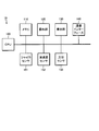
- FIG. 1 shows a configuration example of an acoustic system 1A according to the first embodiment of the present invention.
- the acoustic system 1A includes a terminal device 10, an acoustic device 20, and a plurality of speakers SP1 to SP5.
- the terminal device 10 may be a communication device such as a smartphone, for example.
- the terminal device 10 can communicate with the acoustic device 20.
- the terminal device 10 and the acoustic device 20 may communicate by either wireless or wired.
- the terminal device 10 and the acoustic device 20 may communicate via a wireless LAN (Local Area Network).
- the terminal device 10 can download an application program from a predetermined website on the Internet.
- the application program includes a program used for measuring each direction of the plurality of speakers SP1 to SP5.
- the acoustic device 20 may be a so-called multi-channel amplifier.
- the acoustic device 20 generates output audio signals OUT1 to OUT5 obtained by applying acoustic effects to the input audio signals IN1 to IN5, and supplies the output audio signals OUT1 to OUT5 to the speakers SP1 to SP5.
- the speakers SP1 to SP5 are connected to the acoustic device 20 by wire or wirelessly.
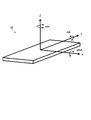
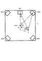
- FIG. 2 shows an arrangement example of the speakers SP1 to SP5 in the listening room R of the acoustic system 1A.
- five speakers SP1 to SP5 are arranged in the listening room R.
- the number of speakers is not limited to five, but may be four or less, or may be six or more.
- the number of input audio signals may be 4 or less, or 6 or more.
- the acoustic system 1A may be a so-called 5.1 surround system including a subwoofer speaker.
- the speaker SP1 is arranged in front of the user A.
- the speaker SP2 is disposed diagonally forward to the right of the user A.
- the speaker SP3 is disposed diagonally to the right of the user A.
- the speaker SP4 is disposed diagonally to the left of the user A.
- the speaker SP5 is arranged diagonally to the left of the user A. The user A feels as if there is a sound source at a specific position by simultaneously listening to the sounds emitted from the speakers SP1 to SP5.
- the acoustic device 20 generates output audio signals OUT1 to OUT5 that sound as if sound is being emitted from a desired position based on the positions where the plurality of speakers SP1 to SP5 are arranged. Further, the acoustic device 20 outputs the generated output audio signals OUT1 to OUT5. Each position of the plurality of speakers SP1 to SP5 is measured in advance.
- FIG. 3 shows an example of the hardware configuration of the terminal device 10.
- the terminal device 10 includes a CPU 100, a memory 110, an operation unit 120, a display unit 130, a communication interface 140, a gyro sensor 151, an acceleration sensor 152, and an orientation sensor 153.
- the CPU 100 functions as a control center for the entire apparatus.
- the memory 110 stores a program such as an application program and functions as a work area for the CPU 100.
- the operation unit 120 accepts input of instructions from the user.
- the display unit 130 displays operation details and the like.
- the communication interface 140 communicates with the outside.
- the X axis coincides with the width direction of the terminal device 10.
- the Y axis coincides with the height direction of the terminal device 10.
- the Z axis coincides with the thickness direction of the terminal device 10.
- the X axis, the Y axis, and the Z axis are orthogonal to each other.
- the pitch angle, the roll angle, and the yaw angle are rotation angles around the X axis, the Y axis, and the Z axis, respectively.
- the gyro sensor 151 detects and outputs the pitch angle, roll angle, and yaw angle of the terminal device 10. From these rotation angles, the direction in which the terminal device 10 is facing can be specified.
- the acceleration sensor 152 measures the X-axis, Y-axis, and Z-axis direction components of the acceleration applied to the terminal device 10.
- the acceleration measured by the acceleration sensor 152 is represented by a three-dimensional vector. Based on the three-dimensional vector, it is possible to identify the direction in which the terminal device 10 is facing.
- the direction sensor 153 measures the direction in which the direction sensor 153 is directed, for example, by detecting geomagnetism. With this orientation, the direction in which the terminal device 10 is facing can be specified.
- the signals output from the gyro sensor 151 and the acceleration sensor 152 are a three-axis coordinate system of the terminal device 10 and are not a coordinate system fixed to the listening dream.
- the direction measured by the gyro sensor 151 and the acceleration sensor 152 is a relative orientation. That is, when the gyro sensor 151 or the acceleration sensor 152 is used, an arbitrary target fixed in the listening room R is used as a reference, and an angle with respect to the reference is obtained as a relative direction.
- the signal output from the orientation sensor 153 is an orientation on the earth and indicates an absolute direction.
- the CPU 100 measures the direction in which the terminal device 10 is directed by using at least one output of the gyro sensor 151, the acceleration sensor 152, and the direction sensor 153 by executing the application program.
- the terminal device 10 includes the gyro sensor 151, the acceleration sensor 152, and the direction sensor 153, but is not limited to such a configuration.
- the terminal device 10 may include only one of the gyro sensor 151, the acceleration sensor 152, and the direction sensor 153.
- the gyro sensor 151 and the acceleration sensor 152 output an angle.
- the angle is a value with respect to an arbitrary reference.
- the reference target may be arbitrarily selected from those in the listening room R.
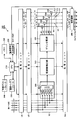
- the acoustic apparatus 20 includes a CPU 210, a communication interface 220, a memory 230, an external interface 240, a reference signal generation circuit 250, a selection circuit 260, and m processing units U1 to Um.
- the CPU 210 functions as a control center for the entire apparatus.
- the communication interface 220 performs communication with the outside.
- the memory 230 stores programs and data and functions as a work area for the CPU 210.
- the external interface 240 receives an input of a signal from an external device such as a microphone and supplies the signal to the CPU 210.
- the reference signal generation circuit 250 generates reference signals Sr1 to Sr5.
- the processing units U1 to Um and the CPU 210 generate output audio signals OUT1 to OUT5 obtained by applying acoustic effects to the input audio signals IN1 to IN5 based on the positions of the plurality of speakers SP1 to SP5.
- the output audio signals OUT1 to OUT5 are signals supplied to the speakers SP1 to SP5, respectively.
- the j-th processing unit Uj includes a virtual sound source generation unit (hereinafter simply referred to as a conversion unit) 300, a frequency correction unit 310, a gain distribution unit 320, and adders 331 to 335 (where “j” is 1 ⁇ j ⁇ any natural number satisfying m).
- the processing units U1, U2,... Uj-1, Uj + 1,... Um are configured in the same manner as the processing unit Uj.
- the conversion unit 300 generates an audio signal of a virtual sound source based on the input audio signals IN1 to IN5.
- the conversion unit 300 includes five switches SW1 to SW5 and a mixer 301.
- the CPU 210 controls the conversion unit 300. More specifically, the CPU 210 stores a virtual sound source management table for managing m virtual sound sources in the memory 230, and controls the conversion unit 300 with reference to the virtual sound source management table.
- the virtual sound source management table stores reference data indicating which input audio signals IN1 to IN5 should be mixed for each virtual sound source.
- the reference data may be, for example, a channel identifier indicating a channel to be mixed, a logical value indicating whether to mix each channel, or the like.
- the CPU 210 refers to the virtual sound source management table and sequentially turns on the switch corresponding to the input audio signal to be mixed among the input audio signals IN1 to IN5 to take in the input audio signal to be mixed.
- input audio signals to be mixed are input audio signals IN1, IN2, and IN5 will be described. In this case, first, the CPU 210 switches on the switch SW1 corresponding to the input audio signal IN1, and switches off the other switches SW2 to SW5.
- the CPU 210 switches on the switch SW2 corresponding to the input audio signal IN2, and switches off the other switches SW1, SW3 to SW5.
- the CPU 210 switches on the switch SW5 corresponding to the input audio signal IN5 and switches off the other switches SW1 to SW4.
- the frequency correction unit 310 performs frequency correction on the output signal of the conversion unit 300. Specifically, under the control of the CPU 210, the frequency correction unit 310 corrects the frequency characteristics of the output signal according to the distance from the position of the virtual sound source to the reference position Pref. More specifically, the frequency correction unit 310 corrects the frequency characteristics of the output signal so that the higher frequency components are attenuated as the distance from the position of the virtual sound source to the reference position Pref increases. This is for reproducing the acoustic characteristic that the attenuation amount of the high frequency component increases as the distance from the virtual sound source to the reference position Pref increases.
- the memory 230 stores an attenuation table in advance.
- the attenuation amount table stores data representing the relationship between the distance from the virtual sound source to the reference position Pref and the attenuation amount of each frequency component.
- the virtual sound source management table stores data representing the position of each virtual sound source.
- the position of the virtual sound source is represented by, for example, three-dimensional orthogonal coordinates, two-dimensional orthogonal coordinates, or polar coordinates with the reference position Pref as the origin.
- the CPU 210 executes the following first to third processes.
- the CPU 210 reads the contents of the virtual sound source management table stored in the memory 230 as the first process. Further, the CPU 210 calculates the distance from each virtual sound source to the reference position Pref based on the contents of the read virtual sound source management table.
- the CPU 210 refers to the attenuation amount table and acquires the attenuation amount of each frequency corresponding to the calculated distance to the reference position Pref.
- the CPU 210 controls the frequency correction unit 310 so that a frequency characteristic corresponding to the acquired attenuation amount is obtained.
- the gain distribution unit 320 distributes the output signal of the frequency correction unit 310 to a plurality of audio signals Aj [1] to Aj [5] for the speakers SP1 to SP5 under the control of the CPU 210. At this time, gain distribution section 320 amplifies the output signal of frequency correction section 310 at a predetermined ratio for each of audio signals Aj [1] to Aj [5]. The magnitude of the gain of the audio signal with respect to the output signal decreases as the distance between each of the speakers SP1 to SP5 and the virtual sound source increases. By such processing, it is possible to form a sound field as if sound is radiated from a place set as the position of the virtual sound source.
- the magnitude of each of the audio signals Aj [1] to Aj [5] may be proportional to the reciprocal of the distance between each of the speakers SP1 to SP5 and the virtual sound source.
- the magnitude of the gain may be set to be proportional to the square or the inverse of the fourth power of the distance between each of the speakers SP1 to SP5 and the virtual sound source.
- the memory 230 stores, for example, a speaker management table.
- a speaker management table data indicating the positions of the speakers SP1 to SP5 and data indicating the distances between the speakers SP1 to SP5 and the reference position Pref are associated with the identifiers of the speakers SP1 to SP5.
- the positions of the speakers SP1 to SP5 are represented by, for example, three-dimensional orthogonal coordinates with the reference position Pref as the origin, polar coordinates, or the like.
- the CPU 210 refers to the virtual sound source management table and the speaker management table stored in the memory 230, and calculates the distance between each speaker SP1 to SP5 and each virtual sound source.
- the CPU 210 calculates the gains of the audio signals Aj [1] to Aj [5] for the speakers SP1 to SP5 based on the calculated distances, and sends control signals for specifying the gains to the processing units U1 to U1. Supply to Um.
- the reference signal generation circuit 250 generates reference signals Sr1 to Sr5 used for measuring the distance between the speakers SP1 to SP5 and the reference position Pref (microphone M) under the control of the CPU 210, and outputs them to the selection circuit 260.
- the CPU 210 causes the reference signal generation circuit 250 to generate the reference signals Sr1 to Sr5 when measuring the distance between each of the plurality of speakers SP1 to SP5 and the position Pref.
- the CPU 210 selects the reference signals Sr1 to Sr5 and controls the selection circuit 260 so as to be supplied to each of the plurality of speakers SP1 to SP5.
- the CPU 210 selects the audio signals Om [1] to Om [5] and applies the output audio signals OUT1 to OUT5 to each of the plurality of speakers SP1 to SP5 when applying the acoustic effect. To control.
- ⁇ Operation of acoustic system> Next, the operation of the acoustic system will be described separately for the specification of the position of the speaker and the specification of the position of the virtual sound source.
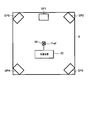
- ⁇ Speaker position identification process> In specifying the position of the speaker, first to third processes are executed. As a first process, the distance between each of the plurality of speakers SP1 to SP5 and the reference position Pref is measured. As a second process, the direction in which each of the plurality of speakers SP1 to SP5 is arranged is measured. As a third process, each position of the plurality of speakers SP1 to SP5 is specified based on the measured distance and direction.
- the microphone M is arranged at the reference position Pref as shown in FIG. 6, and the microphone M is connected to the acoustic device 20.
- the output signal of the microphone M is supplied to the CPU 210 via the external interface 240.
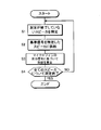
- FIG. 7 shows the contents of the distance measurement processing between the plurality of speakers SP1 to SP5 and the reference position Pref executed by the CPU 210 of the acoustic device 20.
- Step S1 The CPU 210 identifies one speaker that has not been measured as a speaker to be measured. For example, when the distance between the speaker SP1 and the reference position Pref is not measured, the CPU 210 specifies the speaker SP1 as the measurement target speaker.
- Step S2 The CPU 210 controls the reference signal generation circuit 250 so as to generate a reference signal corresponding to the measurement target speaker among the reference signals Sr1 to Sr5. Furthermore, the CPU 210 controls the selection circuit 260 so that the generated reference signal is supplied to the measurement target speaker. At this time, the generated reference signal is output as one of the output audio signals OUT1 to OUT5 corresponding to the measurement target speaker.
- the CPU 210 controls the selection circuit 260 so that the generated reference signal Sr1 is output as the output audio signal OUT1 corresponding to the measurement target speaker SP1.
- Step S3 Based on the output signal of the microphone M, the CPU 210 calculates the distance between the speaker to be measured and the reference position Pref. Further, the CPU 210 records the calculated distance in the speaker management table in association with the identifier of the speaker to be measured.
- Step S4 The CPU 210 determines whether the measurement has been completed for all speakers. If there is a speaker whose measurement has not been completed (NO in step S4), CPU 210 returns the process to step S1, and repeats the process from step S1 to step S4 until the measurement is completed for all speakers. When the measurement is completed for all speakers (YES in step S4), CPU 210 ends the process. With the above processing, the distance from the reference position Pref to the plurality of speakers SP1 to SP5 is measured.
- the distance from the reference position Pref to the speaker SP1 is “L”.
- the position of the speaker SP1 is specified by measuring the direction of the speaker SP1 viewed from the reference position Pref using the terminal device 10.
- FIG. 9 shows the contents of the direction measurement process executed by the CPU 100 of the terminal device 10.
- each direction of the plurality of speakers SP1 to SP5 is specified using at least one of the gyro sensor 151 and the acceleration sensor 152.
- the gyro sensor 151 and the acceleration sensor 152 output an angle.
- the angle reference is the speaker whose arrangement direction is measured first.
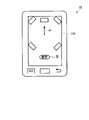
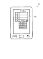
- Step S20 When the direction measurement processing application is activated, the CPU 100 causes the display unit 130 to display an image that prompts the user to perform a setting operation with the terminal device 10 facing the first speaker. For example, when the arrangement direction of the speaker SP1 is set to the first, the CPU 100 displays an arrow a1 directed to the speaker SP1 on the display unit 130 as illustrated in FIG. (Step S21)
- the CPU 100 determines whether a setting operation has been performed by the user. Specifically, the CPU 100 determines whether or not the user has pressed the setting button B (a part of the operation unit 120 described above) shown in FIG. When the setting operation is not performed, the CPU 100 repeats the determination until the setting operation is performed.
- Step S22 When the setting operation is performed, the CPU 100 sets the measurement angle measured by the gyro sensor 151 or the acceleration sensor 152 at the time of the operation as a reference angle. That is, the CPU 100 sets the direction from the reference position Pref toward the speaker SP1 to 0 degrees.
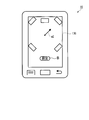
- Step S23 The CPU 100 causes the display unit 130 to display an image that prompts the user to perform the setting operation with the terminal device 10 facing the next speaker. For example, when the arrangement direction of the speaker SP2 is set to the second position, the CPU 100 causes the display unit 130 to display an arrow a2 toward the speaker SP2 as illustrated in FIG.
- Step S24 The CPU 100 determines whether a setting operation has been performed by the user. Specifically, the CPU 100 determines whether or not the user has pressed the setting button B shown in FIG. When the setting operation is not performed, the CPU 100 repeats the determination until the setting operation is performed. (Step S25) When the setting operation is performed, the CPU 100 stores the angle with respect to the reference of the speaker to be measured in the memory 110 using the output value of the gyro sensor 151 or the acceleration sensor 152 at the time of the operation.
- Step S26 The CPU 100 determines whether or not the measurement has been completed for all the speakers. If there is a speaker whose measurement has not been completed (NO in step S26), CPU 100 returns the process to step S23, and repeats the process from step S23 to step S26 until the measurement is completed for all speakers.
- Step S27 When the direction measurement for all the speakers is completed, the CPU 100 transmits the measurement result to the acoustic device 20 using the communication interface 140.
- the direction in which each of the plurality of speakers SP1 to SP5 is arranged is measured. In the example described above, the measurement results are collectively transmitted to the acoustic device 20, but the present invention is not limited to such processing.
- the CPU 100 may transmit the measurement result to the acoustic device 20 every time the arrangement direction of one speaker is measured.
- the arrangement direction of the speaker SP1 as the first measurement object serves as a reference for the angles of the other speakers SP2 to SP5, and the angle with respect to the speaker SP1 is 0 degree. For this reason, transmission of the measurement result regarding the speaker SP1 may be omitted.
- the burden on the user can be reduced by setting the reference to one of the plurality of speakers SP1 to SP5. .
- the reference of the angle does not correspond to any of the plurality of speakers SP1 to SP5 and the target is an arbitrary target arranged in the listening room R will be described.
- the user sets the reference angle by directing the terminal device 10 toward the target and performing a predetermined operation in that state.
- the user designates the direction by performing a predetermined operation with the terminal device 10 facing each of the plurality of speakers SP1 to SP5. Therefore, in the case of an arbitrary target placed in the listening room R, an extra operation is required to be performed with the terminal device 10 facing the target.
- the target is any one of the plurality of speakers SP1 to SP5
- the input operation can be simplified.
- the CPU 210 of the acoustic device 20 uses the communication interface 220 to acquire the arrangement direction (information indicating) of each of the plurality of speakers SP1 to SP5.
- CPU 210 calculates the position of each of the plurality of speakers SP1 to SP5 based on the arrangement direction and distance of each of the plurality of speakers SP1 to SP5. That is, the CPU 210 and the communication interface 220 function as an acquisition unit that acquires the arrangement direction of each of the plurality of speakers SP1 to SP5.
- the arrangement direction of the speaker SP3 is an angle ⁇ and the distance to the speaker SP3 is L3 as shown in FIG.
- the CPU 210 calculates the coordinates (x3, y3) of the speaker SP3 according to the following formula (A).
- (X3, y3) (L3sin ⁇ , L3cos ⁇ ) Equation (A)
- coordinates (x, y) are calculated for the other speakers SP1, SP2, SP4, and SP5.
- CPU 210 calculates the position of each of the plurality of speakers SP1 to SP5 based on the distance from the reference position Pref to each of the plurality of speakers SP1 to SP5 and the arrangement direction of each of the plurality of speakers SP1 to SP5.
- FIG. 13 shows the contents of the virtual sound source position designation process executed by the CPU 100 of the terminal device 10.
- the CPU 100 causes the display unit 130 to display an image that prompts the user to select a channel that is the target of the virtual sound source, and acquires the channel number selected by the user.
- the CPU 100 causes the display unit 130 to display the screen illustrated in FIG.
- the number of virtual sound sources is five. Numbers “1” to “5” are assigned to the respective virtual sound sources.
- the channel can be selected by a pull-down menu. In FIG.
- the channel corresponding to the virtual sound source number 5 is displayed in a pull-down menu.
- the channel includes center, right front, left front, right surround, and left surround.
- Step S31 The CPU 100 causes the display unit 130 to display an image that prompts the user to perform the setting operation with the terminal device facing the target.
- the target is preferably matched with the target used as the reference of the speaker angle in the speaker position specifying process. Specifically, it is preferable to set the target to the speaker SP1 that performs the first setting. In this case, the CPU 100 displays the screen shown in FIG. 10 on the display unit 130 and prompts the user to perform a setting operation.
- Step S32 The CPU 100 determines whether a setting operation has been performed by the user. Specifically, the CPU 100 determines whether or not the user has pressed the setting button B shown in FIG. When the setting operation is not performed, the CPU 100 repeats the determination until the setting operation is performed.
- Step S33 When the setting operation is performed, the CPU 100 sets the measurement angle measured by the gyro sensor 151 or the like at the time of the operation as a reference angle. That is, the CPU 100 sets the direction from the reference position Pref toward the speaker SP1 (target) to 0 degrees.
- Step S34 CPU 100 causes display unit 130 to display an image that prompts the user to perform a setting operation in a state in which the terminal device is oriented in the direction in which the virtual sound source is to be arranged. For example, the CPU 100 causes the display unit 130 to display the screen illustrated in FIG. 15A.
- Step S35 The CPU 100 determines whether a setting operation has been performed by the user. Specifically, the CPU 100 determines whether or not the user has pressed the setting button B shown in FIG. 15A. When the setting operation is not performed, the CPU 100 repeats the determination until the setting operation is performed.
- Step S36 When the setting operation is performed, the CPU 100 stores an angle with respect to the reference of the virtual sound source in the memory 110 using the output value of the gyro sensor 151 and the like at the time of the operation.
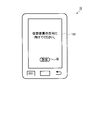
- Step S37 The CPU 100 receives an input of the distance of the virtual sound source from the reference position Pref.
- the CPU 100 displays the screen illustrated in FIG. 15B on the display unit 130 and prompts the user to input the distance to the virtual sound source.
- the CPU 100 acquires the distance input as the distance from the reference position Pref to the virtual sound source.
- Step S38 The CPU 100 transmits the virtual sound source arrangement direction (information indicating) and the distance to the virtual sound source to the acoustic device 20 as a setting result.
- the CPU 210 of the audio device 20 receives the setting result using the communication interface 220.
- the CPU 210 calculates the position of the virtual sound source by a method similar to the calculation of the absolute position of the speaker from the direction and distance of the speaker. Based on the position of the virtual sound source and the positions of the plurality of speakers SP1 to SP5, the CPU 210 controls the processing units U1 to Um so that sound can be heard from the position of the virtual sound source.
- output audio signals OUT1 to OUT5 that have been subjected to acoustic processing so that the sound of the designated channel can be heard from the position of the virtual sound source are generated.
- the arrangement direction of the virtual sound source and the distance to the virtual sound source are transmitted from the terminal device 10 to the acoustic device 20 as a designated position indicating the position of the virtual sound source.
- the terminal device 10 may calculate the coordinates of the designated position from the arrangement direction of the virtual sound source and the distance to the virtual sound source, and may transmit the coordinates to the acoustic device 20.
- any format of information may be transmitted from the terminal device 10 to the audio device 20 as long as the specified position can be specified.
- the angle reference of the plurality of speakers SP1 to SP5 is matched with the angle reference of the virtual sound source. Therefore, the placement direction of the virtual sound source can be executed by the same process as the placement direction of each of the plurality of speakers SP1 to SP5. For this reason, since two processes can be made common, it becomes possible to carry out using the same program module as the specification of the position of the speaker and the specification of the position of the virtual sound source. Further, since the user uses a common target (speaker SP1 in this example) as a reference for the angle, it is not necessary to store individual targets.
- the acoustic system 1 ⁇ / b> A includes the terminal device 10 and the acoustic device 20.
- the terminal device 10 and the acoustic device 20 share various functions.
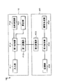
- FIG. 16 shows functions shared by the terminal device 10 and the acoustic device 20 in the acoustic system 1A.
- the terminal device 10 includes an input unit F11, a direction measurement unit F12, a first communication unit F13, and a first control unit F14.
- the input unit F11 receives an instruction input from the user.
- the direction measuring unit F12 measures the arrangement direction of each of the plurality of speakers SP1 to SP5.
- the first communication unit F13 communicates with the acoustic device 20.
- the input unit F11 corresponds to the operation unit 120 described above.
- the first communication unit F13 corresponds to the communication interface 140 described above.
- the direction measuring unit F12 corresponds to the gyro sensor 151, the acceleration sensor 152, the direction sensor 153, and the CPU 100.
- the first control unit F14 corresponds to the CPU 100.
- the first control unit F14 measures the direction in which the speaker is arranged.
- F12 is controlled (step S25 described above).
- the first control unit F14 controls the first communication unit F13 to transmit the arrangement direction of each of the plurality of speakers SP1 to SP5 measured by the direction measurement unit F12 to the acoustic device 20 (step S27 described above). .
- the acoustic device 20 includes a second communication unit F23, a calculation unit F21, a signal generation unit F22, a storage unit F25, and a second control unit F24.
- the second communication unit F23 communicates with the terminal device 10.
- the calculation unit F21 calculates the position of each of the plurality of speakers SP1 to SP5 based on the distance from the reference position Pref to each of the plurality of speakers SP1 to SP5 and the arrangement direction of each of the plurality of speakers SP1 to SP5.
- the signal generation unit F22 generates output audio signals OUT1 to OUT5 generated by applying acoustic effects to the input audio signals IN1 to IN5 for the plurality of speakers SP1 to SP5 based on the positions of the plurality of speakers SP1 to SP5. To do.
- the storage unit F25 stores the distances from the reference position Pref to each of the plurality of speakers SP1 to SP5.
- the second control unit F24 supplies the received arrangement direction of each of the plurality of speakers SP1 to SP5 to the calculation unit F21 and also stores the storage unit
- the distance from the reference position Pref read from F25 to each of the plurality of speakers SP1 to SP5 is supplied to the calculation unit F21.
- the second communication unit F23 corresponds to the communication interface 220 described above.
- the calculation unit F21 and the second control unit F24 correspond to the CPU 210.
- the signal generation unit F22 corresponds to the CPU 210 and the processing units U1 to Um.
- the storage unit F25 corresponds to the memory 230.
- the distance from the reference position Pref to each of the plurality of speakers SP1 to SP5 is measured in advance.
- the terminal device 10 is used to measure the arrangement direction of each of the plurality of speakers SP1 to SP5, and the measurement result is transmitted to the acoustic device 20.
- the calculation unit F21 of the acoustic device 20 can calculate the position of each of the plurality of speakers SP1 to SP5.
- the signal generation unit F22 generates output audio signals OUT1 to OUT5 to which acoustic effects are given based on the calculated positions of the plurality of speakers SP1 to SP5. For this reason, even if the plurality of speakers SP1 to SP5 are not arranged at ideal positions, it is possible to realize acoustic effects such as placement of virtual sound sources and surround in consideration of actual positions.
- FIG. 17 shows a configuration example of an acoustic system 1B according to the first modification.
- the acoustic system 1B is configured in the same manner as the acoustic system 1A illustrated in FIG. 16 except that the calculation unit F21 is deleted from the acoustic device 20 and the calculation unit F21 is provided in the terminal device 10.
- the second control unit F24 controls the second communication unit F23 so as to transmit the distance to each of the plurality of speakers SP1 to SP5 read from the storage unit F25 to the terminal device 10.
- the second control unit F24 supplies the position of each of the plurality of speakers SP1 to SP5 received using the second communication unit F23 to the signal generation unit F22.
- the first control unit F14 measures the arrangement direction of the speakers.
- the direction measuring unit F12 is controlled to do so.
- the first control unit F14 has a plurality of units based on the directions of the plurality of speakers SP1 to SP5 measured by the direction measuring unit F12 and the distances of the plurality of speakers SP1 to SP5 received using the first communication unit F13.
- the calculation unit F21 is controlled so as to calculate the position of each of the speakers SP1 to SP5.
- the first control unit F14 controls the first communication unit F13 to transmit the positions of the plurality of speakers SP1 to SP5 calculated by the calculation unit F21 to the acoustic device 20.
- the terminal device 10 calculates the position of each of the plurality of speakers SP1 to SP5. Therefore, the processing load of the audio device 20 can be reduced.
- the acoustic device 20 stores the positions of the plurality of speakers SP1 to SP5 received from the terminal device 10, and these positions can be used for the subsequent application of acoustic effects.
- the storage unit F25 provided in the acoustic device 20 stores the distances between the plurality of speakers SP1 to SP5.
- the terminal device 10 may include a storage unit F25.
- the terminal device 10 transmits the arrangement direction of each of the plurality of speakers SP1 to SP5 measured by the direction measuring unit F12 and the distance of each of the plurality of speakers SP1 to SP5 stored in the storage unit F25 to the acoustic device 20. To do.
- the calculation unit F21 of the acoustic device 20 calculates the position of each of the plurality of speakers SP1 to SP5 based on the arrangement direction of each of the plurality of speakers SP1 to SP5 and the distance to each of the plurality of speakers SP1 to SP5.
- the terminal device 10 may include a storage unit F25 and a calculation unit F21.
- the calculation unit F21 may transmit the calculated positions of the plurality of speakers SP1 to SP5 to the acoustic device 20.
- the positions of the plurality of speakers SP1 to SP5 may be stored in the memory 230 of the acoustic device 20.
- output audio signals OUT1 to OUT5 to which acoustic effects are given may be generated based on the stored positions of the plurality of speakers SP1 to SP5.
- the measurement of the arrangement direction of each of the plurality of speakers SP1 to SP5 is measured at the reference position Pref when the position where the user A views in the listening room R is the reference position Pref.
- the arrangement direction of each of the plurality of speakers SP1 to SP5 may be measured at an arbitrary position. In this case, the following processing is performed. That is, the relative positional relationship between the arbitrary position and the reference position is transmitted from the terminal device 10 to the acoustic device 20.
- the calculation unit F21 is based on the relative positional relationship, the arrangement direction of the plurality of speakers SP1 to SP5 viewed from an arbitrary position, and the distance between each of the plurality of speakers SP1 to SP5 and the reference position Pref.
- the position of each of the plurality of speakers SP1 to SP5 is calculated. More specifically, the calculation unit F21 determines the direction of the relative positional relationship of the plurality of speakers viewed from the arbitrary position based on the relative positional relationship, and the direction of the plurality of speakers SP1 to SP5 viewed from the reference position Pref. Convert to In addition, the calculation unit F21 calculates the position of each of the plurality of speakers SP1 to SP5 based on the conversion result and the distance between each of the plurality of speakers SP1 to SP5 and the reference position Pref.
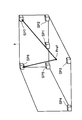
- the angle conversion method will be described with reference to FIG.
- the arbitrary position P is determined as a position moved by ( ⁇ x, ⁇ y) from the reference position Pref.
- the distance from the reference position Pref to the speaker SP1 is defined as “L 1 ”.
- the distance from the reference position Pref to the speaker SP2 is defined as “L 2 ”.
- the distance from the reference position Pref to the predetermined position P is defined as “L 3 ”.
- the distance from the predetermined position P to the speaker SP2 is defined as “L 4 ”.
- the angle of the speaker SP2 with respect to the speaker SP1 when viewed from the reference position Pref is defined as ⁇ .
- the angle of the speaker SP2 with respect to the speaker SP1 when viewed from the predetermined position P is defined as “ ⁇ ′”.
- the angles ⁇ b, ⁇ c, ⁇ d, and ⁇ e are determined as shown in FIG.
- L 4 2 L 2 2 + L 3 2 + 2L 2 L 3 cos ( ⁇ e) (8)
- ⁇ e can be expressed by equation (9).
- cos ( ⁇ e) (L 2 + L 3 2 ⁇ L 4 2 ) / (2L 2 L 3 )
- ⁇ e acos ⁇ (L 2 2 + L 3 2 ⁇ L 4 2 ) / (2L 2 L 3 ) ⁇ Equation (9)
- Equation (11) “ ⁇ ′” and “L 2 ” are known. “L 3 ” is also known from Equation (7). “ ⁇ d” is also known from Equation (6). Therefore, “L 4 ” can be obtained by substituting Equations (6) and (7) into Equation (11). Furthermore, if “L 4 ” calculated by equation (11), “L 3 ” calculated by equation (7), and known “L 2 ” are substituted into equation (9), “ ⁇ e” is calculated. it can. “ ⁇ ” can be obtained by substituting “ ⁇ e” and “ ⁇ b” calculated by Equation (4) into Equation (1).
- “ ⁇ x” and “ ⁇ y” are relative coordinates from the predetermined position P to the reference position Pref. Therefore, “ ⁇ x” and “ ⁇ y” can be obtained by using the integration result of the output signal of the triaxial acceleration sensor 152 of the draft device 10 and the output signal of the direction sensor 153. Specifically, when the user inputs a start instruction using the operation unit 120 at an arbitrary position P, integration starts, and after the user moves to the reference position Pref, the user uses the operation unit 120 to end the operation. If you enter, the integration should be terminated. Further, the user may input “ ⁇ x” and “ ⁇ y” using the operation unit 120.
- the direction measuring unit F12 outputs the angle with respect to the reference as the direction, with the speaker SP1 as the reference.
- the present invention is not limited to such a configuration.
- An arbitrary target placed in the listening room R may be used as a reference, and an angle with respect to the reference may be measured as a direction.
- the direction measuring unit F12 may set the television as a target, output the angle relative to the reference as a direction, with the television (target) as a reference. .
- the first control unit F14 sets a reference angle when the user uses the input unit F11 to input that the user is facing the terminal device 10 on a television serving as a reference target.
- the direction measuring unit F12 is controlled so that When the user operates the input unit F11 with the terminal device 10 facing each of the plurality of speakers SP1 to SP5, the first control unit F14 sets the direction measuring unit F12 to measure the direction of the speaker. Control.
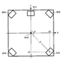
- a plurality of speakers SP1 to SP7 may be arranged three-dimensionally as shown in FIG.
- the speaker SP6 is arranged obliquely upward on the left front when viewed from the reference position Pref.
- a speaker SP7 is disposed obliquely on the right front side. Even when a plurality of speakers SP1 to SP7 are arranged three-dimensionally in this way, the direction of each of the plurality of speakers SP1 to SP7 can be measured, and the angle of each speaker SP2 to SP7 can be measured with respect to the speaker SP1. That's fine.
- the information which shows the arrangement direction of the speaker measured in the terminal device is transmitted to an audio equipment. For this reason, when the distance to the speaker is known, even if the speaker is deviated from the ideal position, the actual positions of the plurality of speakers can be calculated by the acoustic device, and a desired acoustic effect can be imparted. In addition, since the user only has to operate the input unit with the terminal device directed toward the target speaker in the direction measurement, the user can easily measure the speaker arrangement direction.
- the distance to the speaker is transmitted from the acoustic device to the terminal device. The position of the speaker is calculated based on the arrangement direction of the speaker measured by the terminal device and the received distance.
- the acoustic device does not need to include a calculation unit, and the configuration of the acoustic device can be simplified.
- the acceleration sensor and gyro sensor which detect a relative direction as a direction measurement part, it can set on the basis of a target. For this reason, the angle which the arrangement direction of a target object and the arrangement direction of a speaker comprise can be obtained.
- the specified direction is input based on the same target as the reference in the measurement of the speaker arrangement direction. To do. Therefore, the angle with respect to the reference of the virtual sound source can be handled in the same manner as the angle with respect to the reference of the speaker.
- the virtual sound source arrangement process can be simplified in the signal generation unit. Further, by using the same target as a reference, a relative angular error between the speaker and the virtual sound source can be reduced. According to the above embodiment, it is possible to simplify the labor of inputting the reference by using the target as the predetermined speaker.
- the order in which the user designates the speaker arrangement direction using the input unit may be determined in advance.
- the target may be a speaker designated first among a plurality of speakers. In this case, information indicating the arrangement direction of the second and subsequent speakers is given as an angle with respect to the first speaker.
- the predetermined speaker may be a speaker in an arbitrary order. In this case, a predetermined speaker angle may be subtracted from the angles of other speakers to specify the arrangement direction of the plurality of speakers.
- the present invention can be applied to an acoustic device, an acoustic system, and a method.
Landscapes
- Physics & Mathematics (AREA)
- Engineering & Computer Science (AREA)
- Acoustics & Sound (AREA)
- Signal Processing (AREA)
- Health & Medical Sciences (AREA)
- General Health & Medical Sciences (AREA)
- Otolaryngology (AREA)
- Stereophonic System (AREA)
- Stereophonic Arrangements (AREA)
Abstract
音響装置は、第1のスピーカに端末装置が向けられた状態で前記端末装置によって測定された、前記第1のスピーカの配置方向を示す第1情報を取得する取得部と、基準位置から前記第1のスピーカまでの距離と、前記第1情報とに少なくとも基づいて、前記第1のスピーカの位置を算出する算出部とを備える。
Description
この発明は、スピーカの位置を算出する装置に関する。
本願は、2013年4月17日に、日本に出願された特願2013-086875号に基づき優先権を主張し、その内容をここに援用する。
本願は、2013年4月17日に、日本に出願された特願2013-086875号に基づき優先権を主張し、その内容をここに援用する。
複数のスピーカで合成音像による音場を形成する音響装置が知られている。例えば、DVD(Digital Versatile Disc)のように5.1チャンネル等のマルチチャンネル音声信号が記録されているオーディオソースがある。このようなオーディオソースを再生する音響装置が一般家庭でも普及しつつある。リスニングルーム内の推奨位置に各スピーカが配置されていれば、音響装置を用いてオーディオソースを再生すると、サラウンドなどの音響再生効果が得られる。一方、スピーカの配置が推奨位置と異なる場合には、音像定位が不適切になる可能性があった。スピーカから出た音をマイクロフォンで収音することで、スピーカの位置のずれを算出し、算出結果に基づいてスピーカが出す音を補正することにより、所望の音場を形成する技術が知られている(例えば、特許文献1参照)。
しかしながら、従来の音響装置では、スピーカの三次元的な位置を特定するためには、マイクロフォンが4個必要となる。高さ方向のずれを無視することとしても、スピーカの二次元的な位置を特定するためには、マイクロフォンが3個必要となる。いずれの場合においても、オーディオシステムが高価になるという課題がある。
1個のマイクロフォンを移動させて4回あるいは3回測定を行えば、1個のマイクロフォンでスピーカの位置を特定できる。しかしながら、この場合、測定に時間がかかるという課題がある。また、マイクロフォンを正確に移動させるため、台座などが必要になるという課題がある。
1個のマイクロフォンを移動させて4回あるいは3回測定を行えば、1個のマイクロフォンでスピーカの位置を特定できる。しかしながら、この場合、測定に時間がかかるという課題がある。また、マイクロフォンを正確に移動させるため、台座などが必要になるという課題がある。
本発明は、上述した事情に鑑みてなされた。本発明の目的の一例は、簡易な構成で、スピーカの位置を特定することである。
本発明の実施態様に係る音響装置は、第1のスピーカに端末装置が向けられた状態で前記端末装置によって測定された、前記第1のスピーカの配置方向を示す第1情報を取得する取得部と、基準位置から前記第1のスピーカまでの距離と、前記第1情報とに少なくとも基づいて、前記第1のスピーカの位置を算出する算出部とを備える。
上記の音響装置によれば、算出部は、距離および方向という2つの要素に基づいて、スピーカの配置位置を算出する。よって、基準位置からスピーカまでの距離が既知の場合、スピーカの配置方向を取得するだけでスピーカの位置を特定することができる。また、特定したスピーカの位置に基づいて音響効果を付与することができる。スピーカまでの距離は簡易な構成で測定することができる。よって、スピーカが理想位置からずれている場合でも、簡易な方法で、所望の音響効果を付与することができる。
取得部が取得するスピーカの配置方向を示す情報は、距離の基準となる基準位置から見た配置方向を示してもよいし、任意位置から見た配置方向を示してもよい。情報が任意位置から見た配置方向を示す場合は、取得部は、任意位置から見たスピーカの配置方向及び任意位置と基準位置との相対位置とを取得してもよい。また、算出部は、相対位置と、任意位置から見たスピーカの配置方向と、スピーカと基準位置との間の距離とに基づいて、スピーカの位置を算出してもよい。より具体的には、算出部は、相対位置に基づいて、任意位置から見たスピーカの位置方向示す情報を基準位置から見たスピーカの配置方向を示す情報に変換してもよい。さらに、算出部は、変換結果およびスピーカと基準位置との間の距離に基づいて、スピーカの位置を算出してもよい。
本発明の実施態様に係る音響システムは、第1のスピーカに端末装置が向けられた状態で前記第1のスピーカの配置方向を示す第1情報を測定する方向測定部と、基準位置から前記第1のスピーカまでの距離と、前記第1情報とに少なくとも基づいて、前記第1のスピーカの位置を算出する算出部とを備える。
スピーカまでの距離は簡易な構成で測定することが可能である。上記の音響システムによれば、算出部は、距離および方向という2つの要素に基づいて、スピーカの位置を算出する。よって、スピーカが理想位置からずれている場合でも、簡易な方法で、所望の音響効果を付与することができる。
スピーカまでの距離は簡易な構成で測定することが可能である。上記の音響システムによれば、算出部は、距離および方向という2つの要素に基づいて、スピーカの位置を算出する。よって、スピーカが理想位置からずれている場合でも、簡易な方法で、所望の音響効果を付与することができる。
本発明の実施態様に係る音響システムのための方法は、第1のスピーカに端末装置が向けられた状態で前記第1のスピーカの配置方向を示す第1情報を測定し、基準位置から前記第1のスピーカまでの距離と、前記第1情報とに少なくとも基づいて、前記第1のスピーカの位置を算出することを含む。
以下、本発明の実施形態について図面を参照しつつ説明する。
<音響システムの構成>
図1に、本発明の第1実施形態に係る音響システム1Aの構成例を示す。音響システム1Aは、端末装置10と、音響装置20と、複数のスピーカSP1~SP5とを備える。端末装置10は、例えば、スマートフォンなどの通信機器であってもよい。端末装置10は、音響装置20と通信可能である。端末装置10と音響装置20とは無線又は有線のいずれにより通信を行ってもよい。例えば、端末装置10と音響装置20とは、無線LAN(Local Area Network)を介して通信してもよい。端末装置10は、インターネット上の所定のウェブサイトからアプリケーションプログラムをダウンロードすることができる。アプリケーションプログラムには、複数のスピーカSP1~SP5の各方向を測定するために用いるプログラムが含まれる。
音響装置20は、いわゆるマルチチャネルアンプであってもよい。音響装置20は、入力オーディオ信号IN1~IN5に音響効果を付与した出力オーディオ信号OUT1~OUT5を生成し、出力オーディオ信号OUT1~OUT5をスピーカSP1~SP5に供給する。スピーカSP1~SP5は、音響装置20と有線又は無線にて接続されている。
図2に、音響システム1AのリスニングルームR内のスピーカSP1~SP5の配置例を示す。この例では、5つのスピーカSP1~SP5がリスニングルームR内に配置されている。しかしながら、スピーカの数は、5つに限らず、4つ以下であってもよいし、6つ以上であってもよい。同様に、入力オーディオ信号の数も、4つ以下であってもよいし、6つ以上であってもよい。例えば、音響システム1Aは、サブウーハのスピーカを含む、いわゆる5.1サラウンドシステムであってもよい。
利用者Aは、あらかじめ定められた位置(以下「基準位置」と称する。)Prefで、スピーカSP1~SP5から放音された音を視聴する。この例では、スピーカSP1は利用者Aの正面に配置されている。スピーカSP2は利用者Aの右斜め前方に配置されている。スピーカSP3は利用者Aの右斜め後方に配置されている。スピーカSP4は利用者Aの左斜め後方に配置されている。スピーカSP5は利用者Aの左斜め前方に配置される。利用者Aは、スピーカSP1~SP5から放音された音を同時に聞くことにより、特定の位置に音源があるかのように感じる。
音響装置20は、複数のスピーカSP1~SP5が配置された位置に基づいて、所望の位置から音が出ているように聞こえる出力オーディオ信号OUT1~OUT5を生成する。さらに、音響装置20は、生成した出力オーディオ信号OUT1~OUT5を出力する。複数のスピーカSP1~SP5の各位置は、あらかじめ測定される。
図3に、端末装置10のハードウェア構成の一例を示す。図3に示す例において、端末装置10は、CPU100、メモリ110、操作部120、表示部130、通信インターフェース140、ジャイロセンサ151、加速度センサ152、及び方位センサ153を備える。CPU100は、装置全体の制御中枢として機能する。メモリ110は、アプリケーションプログラムなどのプログラムを記憶し、またCPU100の作業領域として機能する。操作部120は、利用者からの指示の入力を受け付ける。表示部130は、操作内容などを表示する。通信インターフェース140は、外部と通信を行う。
図4に示す例において、X軸は端末装置10の幅方向と一致する。Y軸は端末装置10の高さ方向と一致する。Z軸は端末装置10の厚み方向と一致する。X軸、Y軸及びZ軸は互いに直交する。ピッチ角(pitch)、ロール角(roll)、及びヨー角(yaw)はそれぞれ、X軸、Y軸、及びZ軸周りの回転角である。ジャイロセンサ151は、端末装置10のピッチ角、ロール角及びヨー角を検出および出力する。これらの回転角度から、端末装置10の向いている方向を特定することができる。加速度センサ152は、端末装置10に加えられた加速度のX軸、Y軸及びZ軸方向成分を測定する。この場合、加速度センサ152が測定する加速度は、三次元ベクトルで表わされる。三次元ベクトルに基づいて端末装置10の向いている方向を特定することができる。方位センサ153は、例えば、地磁気を検出することにより、方位センサ153が向いている方位を測定する。この方位により、端末装置10の向いている方向を特定することができる。ジャイロセンサ151及び加速度センサ152が出力する信号は、端末装置10の有する3軸の座標系であって、リスニングリームに固定の座標系では無い。従って、ジャイロセンサ151及び加速度センサ152で測定される方向は相対的な方位である。即ち、ジャイロセンサ151または加速度センサ152を用いた場合、リスニングルームR内に固定されている任意の目標物を基準とし、基準に対する角度が相対的な方向として得られる。一方、方位センサ153が出力する信号は、地球上の方位であり、絶対的な方向を示す。
CPU100は、アプリケーションプログムを実行することによって、ジャイロセンサ151、加速度センサ152、及び方位センサ153のうち少なくとも一つの出力を用いて、端末装置10が向いている方向を測定する。図3に示す例では、端末装置10は、ジャイロセンサ151、加速度センサ152、及び方位センサ153を備えるが、このような構成に限られない。端末装置10は、ジャイロセンサ151、加速度センサ152、及び方位センサ153のうちの一つのみを備えていてもよい。ジャイロセンサ151及び加速度センサ152は、角度を出力する。角度は任意の基準に対する値である。基準となる目標物は、リスニングルームR内の物から任意に選択してよい。具体例として、複数のスピーカSP1~SP5のうち第1番目にその方向が測定されるスピーカが目標物として選択される場合を後述する。
一方、方位センサ153を用いて、複数のスピーカSP1~SP5の方向を測定する場合は、基準の方向の入力は不要である。その理由は、方位センサ153からは、絶対的な方向を示す値が出力されるからである。
一方、方位センサ153を用いて、複数のスピーカSP1~SP5の方向を測定する場合は、基準の方向の入力は不要である。その理由は、方位センサ153からは、絶対的な方向を示す値が出力されるからである。
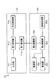
図5に示される例において、音響装置20は、CPU210、通信インターフェース220、メモリ230、外部インターフェース240、基準信号生成回路250、選択回路260、及びm個の処理ユニットU1~Umを備える。CPU210は、装置全体の制御中枢として機能する。通信インターフェース220は、外部と通信を実行する。メモリ230は、プログラムやデータを記憶し、またCPU210の作業領域として機能する。外部インターフェース240は、マイクロフォンなどの外部装置からの信号の入力を受け付け、その信号をCPU210に供給する。基準信号生成回路250は、基準信号Sr1~Sr5を生成する。処理ユニットU1~Um及びCPU210は、複数のスピーカSP1~SP5の各位置に基づいて、入力オーディオ信号IN1~IN5に音響効果を付与した出力オーディオ信号OUT1~OUT5を生成する。出力オーディオ信号OUT1~OUT5はそれぞれ、スピーカSP1~SP5に供給される信号である。
j番目の処理ユニットUjは、仮想音源化部(以下、単に変換部と称する)300、周波数補正部310、ゲイン分配部320、及び加算器331~335を有する(“j”は1≦j≦mを満たす任意の自然数である)。処理ユニットU1、U2、…Uj-1、Uj+1、…Umは、処理ユニットUjと同様に構成されている。
変換部300は、入力オーディオ信号IN1~IN5に基づいて、仮想音源のオーディオ信号を生成する。この例では、m個の処理ユニットU1~Umが設けられているので、m個の仮想音源に対応した出力オーディオ信号OUT1~OUT5を生成することができる。変換部300は、5個のスイッチSW1~SW5とミキサ301とを備える。CPU210は変換部300を制御する。より具体的には、CPU210は、メモリ230にm個の仮想音源を管理する仮想音源管理テーブルを記憶しておき、仮想音源管理テーブルを参照して変換部300を制御する。仮想音源管理テーブルには、各仮想音源について、どの入力オーディオ信号IN1~IN5をミキシングすればよいかを表わす参照データが格納されている。参照データは、例えば、ミキシングするチャネルを示すチャネル識別子や、それぞれのチャネルについてミキシングするか否かを表わす論理値などであってもよい。CPU210は、仮想音源管理テーブルを参照して入力オーディオ信号IN1~IN5のうちミキシングの対象となる入力オーディオ信号に対応するスイッチを順次にオンにして、ミキシングの対象となる入力オーディオ信号を取り込む。具体例として、ミキシングの対象となる入力オーディオ信号が入力オーディオ信号IN1、IN2及びIN5である場合について説明する。この場合、まず、CPU210は、入力オーディオ信号IN1に対応するスイッチSW1をオンに切り替え、他のスイッチSW2~SW5をオフに切り替える。次に、CPU210は、入力オーディオ信号IN2に対応するスイッチSW2をオンに切り替え、他のスイッチSW1、SW3~SW5をオフに切り替える。その次に、CPU210は、入力オーディオ信号IN5に対応するスイッチSW5をオンに切り替え、他のスイッチSW1~SW4をオフに切り替える。
周波数補正部310は、変換部300の出力信号に周波数補正を施す。具体的には、CPU210の制御の下、周波数補正部310は、仮想音源の位置から基準位置Prefまでの距離に応じて、出力信号の周波数特性を補正する。より具体的には、周波数補正部310は、仮想音源の位置から基準位置Prefまでの距離が遠いほど、高域の周波数成分を大きく減衰させるように出力信号の周波数特性を補正する。これは、仮想音源から基準位置Prefまでの距離が大きいほど、高周波成分の減衰量が大きくなるという音響特性を再現するためである。
メモリ230は、減衰量テーブルをあらかじめ記憶している。減衰量テーブルには、仮想音源から基準位置Prefまでの距離と各周波数成分の減衰量との関係を表わすデータが格納されている。仮想音源管理テーブルには、それぞれの仮想音源の位置を表わすデータが格納されている。仮想音源の位置は、例えば、基準位置Prefを原点とする三次元直交座標、二次元直交座標、あるいは極座標などによって表わされる。
CPU210は、以下の第1~第3の処理を実行する。CPU210は、第1の処理として、メモリ230が記憶した仮想音源管理テーブルの内容を読み出する。さらに、CPU210は、読み出した仮想音源管理テーブルの内容に基づいて、それぞれの仮想音源から基準位置Prefまでの距離を算出する。CPU210は、第2の処理として、減衰量テーブルを参照して、算出した基準位置Prefまでの距離に応じた各周波数の減衰量を取得する。CPU210は、第3の処理として、取得した減衰量に応じた周波数特性が得られるように周波数補正部310を制御する。
ゲイン分配部320は、CPU210の制御の下、周波数補正部310の出力信号をスピーカSP1~SP5用に複数のオーディオ信号Aj[1]~Aj[5]に分配する。この時、ゲイン分配部320は、周波数補正部310の出力信号を、オーディオ信号Aj[1]~Aj[5]ごとに、所定の割合で増幅する。出力信号に対するオーディオ信号のゲインの大きさは、スピーカSP1~SP5各々と仮想音源との間の距離が遠いほど小さくなる。このような処理により、あたかも仮想音源の位置として設定された場所から音が放射されているかような音場を形成することができる。例えば、オーディオ信号Aj[1]~Aj[5]各々のゲインの大きさは、スピーカSP1~SP5各々と仮想音源との間の距離の逆数に比例してもよい。別法として、ゲインの大きさは、スピーカSP1~SP5各々と仮想音源との間の距離の二乗あるいは四乗の逆数に比例するように設定してもよい。スピーカSP1~SP5のいずれかと仮想音源との間の距離がほぼ0である場合は、それ以外のスピーカSP1~SP5に対するオーディオ信号Aj[1]~Aj[5]のゲインを0に設定してもよい。
メモリ230は、例えば、スピーカ管理テーブルを記憶している。スピーカ管理テーブルには、各スピーカSP1~SP5の識別子と対応づけられた状態で、各スピーカSP1~SP5の位置を示すデータ及び各スピーカSP1~SP5と基準位置Prefとの間の距離を示すデータが格納される。スピーカSP1~SP5の位置は、例えば、基準位置Prefを原点とする三次元直交座標や、極座標などによって表わされる。
CPU210は、第1の処理として、メモリ230に格納した仮想音源管理テーブルとスピーカ管理テーブルとを参照して、各スピーカSP1~SP5と各仮想音源との間の距離を算出する。CPU210は、第2の処理として、算出した距離に基づいて各スピーカSP1~SP5に対するオーディオ信号Aj[1]~Aj[5]のゲインを算出し、ゲインを指定する制御信号を各処理ユニットU1~Umに供給する。
処理ユニットUjの加算器331~335は、ゲイン分配部320から出力されるオーディオ信号Aj[1]~Aj[5]と、前段の処理ユニットUj-1から供給されるオーディオ信号Oj-1[1]~Oj-1[5]とを加算して、オーディオ信号Oj[1]~Oj[5]を出力する。その結果、処理ユニットUmから出力されるオーディオ信号Om[k]は、Om[k]=A1[k]+A2[k]+…+Aj[k]+…+Am[k]となる(“k”は1から5までの任意の自然数である)。
基準信号生成回路250は、CPU210の制御の下、スピーカSP1~SP5と基準位置Pref(マイクロフォンM)と間の距離の測定に用いられる基準信号Sr1~Sr5を生成して選択回路260に出力する。CPU210は、複数のスピーカSP1~SP5各々と位置Prefと間の距離を測定する際に、基準信号生成回路250に基準信号Sr1~Sr5を生成させる。CPU210は、複数のスピーカSP1~SP5各々までの距離を測定する場合には、基準信号Sr1~Sr5を選択し、複数のスピーカSP1~SP5の各々に供給するように選択回路260を制御する。CPU210は、音響効果を付与する場合には、オーディオ信号Om[1]~Om[5]を選択し、出力オーディオ信号OUT1~OUT5を複数のスピーカSP1~SP5の各々に供給するように選択回路260を制御する。
<音響システムの動作>
次に、音響システムの動作を、スピーカの位置の特定と、仮想音源の位置の指定とに分けて説明する。
<スピーカの位置の特定処理>
スピーカの位置の特定では、第1~第3の処理を実行する。第1の処理として、複数のスピーカSP1~SP5各々と基準位置Prefとの間の距離を測定する。第2の処理として、複数のスピーカSP1~SP5各々が配置されている方向を測定する。第3の処理として、測定された距離及び方向に基づいて、複数のスピーカSP1~SP5の各位置を特定する。
次に、音響システムの動作を、スピーカの位置の特定と、仮想音源の位置の指定とに分けて説明する。
<スピーカの位置の特定処理>
スピーカの位置の特定では、第1~第3の処理を実行する。第1の処理として、複数のスピーカSP1~SP5各々と基準位置Prefとの間の距離を測定する。第2の処理として、複数のスピーカSP1~SP5各々が配置されている方向を測定する。第3の処理として、測定された距離及び方向に基づいて、複数のスピーカSP1~SP5の各位置を特定する。
距離の測定においては、図6に示すようにマイクロフォンMを基準位置Prefに配置し、マイクロフォンMを音響装置20に接続する。マイクロフォンMの出力信号は外部インターフェース240を介してCPU210に供給される。図7に、音響装置20のCPU210が実行する複数のスピーカSP1~SP5と基準位置Prefとの間の距離の測定処理の内容を示す。
(ステップS1)
CPU210は、測定対象のスピーカとして、測定が終了していないスピーカを一つ特定する。例えば、スピーカSP1と基準位置Prefとの間の距離の測定を行っていない場合、CPU210は、測定対象のスピーカとして、スピーカSP1を特定する。
(ステップS2)
CPU210は、基準信号Sr1~Sr5のうち、測定対象のスピーカと対応する基準信号を生成するように基準信号生成回路250を制御する。さらに、CPU210は、生成された基準信号が測定対象のスピーカに供給されるように選択回路260を制御する。このとき、生成された基準信号は、測定対象のスピーカに対応する出力オーディオ信号OUT1~OUT5のいずれかとして出力される。例えば、CPU210は、生成された基準信号Sr1を、測定対象のスピーカSP1に対応する出力オーディオ信号OUT1として出力されるように選択回路260を制御する。
(ステップS3)
CPU210はマイクロフォンMの出力信号に基づいて、測定対象のスピーカと基準位置Prefとの間の距離を算出する。さらに、CPU210は、測定対象のスピーカの識別子と対応づけて、算出した距離をスピーカ管理テーブルに記録する。
(ステップS4)
CPU210は、全てのスピーカについて測定が終了したか否かを判定する。測定が終了していないスピーカがある場合には(ステップS4においてNO)、CPU210は処理をステップS1に戻し、全てのスピーカについて測定が終了するまで、ステップS1からステップS4までの処理を繰り返す。全てのスピーカについて測定が終了すると(ステップS4においてYES)、CPU210は処理を終了する。
以上の処理によって基準位置Prefから複数のスピーカSP1~SP5までの距離が測定される。
例えば、基準位置PrefからスピーカSP1までの距離が“L”であると仮定する。この場合、図8に示すようにスピーカSP1は、基準位置Prefから半径Lの円上に存在することが分かる。しかしながら、スピーカSP1が、円上のどの位置に存在するかは特定されない。そこで、本実施形態では、端末装置10を用いて、基準位置Prefから見たスピーカSP1の方向を測定することによって、スピーカSP1の位置を特定する。
図9は、端末装置10のCPU100が実行する方向測定処理の内容を示す。この例では、ジャイロセンサ151及び加速度センサ152の少なくとも一方を用いて複数のスピーカSP1~SP5の各方向を特定する。上述したようにジャイロセンサ151及び加速度センサ152は角度を出力する。この例において、角度の基準は、第1番目に配置方向が測定されるスピーカである。
(ステップS20)
方向測定処理のアプリケーションが起動されると、CPU100は、利用者に第1番目のスピーカに端末装置10を向けた状態で設定操作を行うように促す画像を表示部130に表示させる。例えば、スピーカSP1の配置方向を第1番目に設定する場合、CPU100は、図10に示すようにスピーカSP1に向けた矢印a1を表示部130に表示する。
(ステップS21)
CPU100は、利用者によって設定操作がなされたか否かを判定する。具体的にはCPU100は、図10に示す設定ボタンB(上述した操作部120の一部)を利用者が押下したか否かを判定する。設定操作がなされていない場合は、CPU100は、設定操作がなされるまで判定を繰り返す。
(ステップS22)
CPU100は、設定操作がなされると、その操作時点においてジャイロセンサ151または加速度センサ152によって測定された測定角度を基準となる角度に設定する。即ち、CPU100は、基準位置PrefからスピーカSP1に向かう方向を0度に設定する。
(ステップS23)
CPU100は、次のスピーカに端末装置10を向けた状態で設定操作を行うように促す画像を表示部130に表示させる。例えば、スピーカSP2の配置方向を第2番目に設定する場合、CPU100は、図11に示すようにスピーカSP2に向けた矢印a2を表示部130に表示させる。
CPU100は、次のスピーカに端末装置10を向けた状態で設定操作を行うように促す画像を表示部130に表示させる。例えば、スピーカSP2の配置方向を第2番目に設定する場合、CPU100は、図11に示すようにスピーカSP2に向けた矢印a2を表示部130に表示させる。
(ステップS24)
CPU100は、利用者によって設定操作がなされたか否かを判定する。具体的には、CPU100は、図11に示す設定ボタンBを利用者が押下したか否かを判定する。設定操作がなされていない場合は、CPU100は、設定操作がなされるまで判定を繰り返す。
(ステップS25)
CPU100は、設定操作がなされると、その操作時点におけるジャイロセンサ151または加速度センサ152の出力値を用いて、測定対象のスピーカの基準に対する角度をメモリ110に記憶する。
CPU100は、利用者によって設定操作がなされたか否かを判定する。具体的には、CPU100は、図11に示す設定ボタンBを利用者が押下したか否かを判定する。設定操作がなされていない場合は、CPU100は、設定操作がなされるまで判定を繰り返す。
(ステップS25)
CPU100は、設定操作がなされると、その操作時点におけるジャイロセンサ151または加速度センサ152の出力値を用いて、測定対象のスピーカの基準に対する角度をメモリ110に記憶する。
(ステップS26)
CPU100は、全てのスピーカについて測定が終了したか否かを判定する。測定が終了していないスピーカがある場合には(ステップS26においてNO)、CPU100は処理をステップS23に戻し、全てのスピーカについて測定が終了するまで、ステップS23からステップS26までの処理を繰り返す。
(ステップS27)
全てのスピーカについて方向の測定が終了すると、CPU100は、通信インターフェース140を用いて測定結果を音響装置20に送信する。
以上の処理により、複数のスピーカSP1~SP5各々の配置されている方向が測定される。上述した例では測定結果をまとめて音響装置20に送信したが、このような処理に限られない。CPU100は、一つのスピーカの配置方向が測定される度に、測定結果を音響装置20に送信してもよい。上記のように、第1番目の測定対象であるスピーカSP1の配置方向は、他のスピーカSP2~SP5の角度の基準としてはたらき、スピーカSP1に関する角度は0度である。このため、スピーカSP1に関する測定結果の送信は省略してもよい。
このように複数のスピーカSP1~SP5各々の配置方向を基準に対する角度を用いて特定する場合に、基準を複数のスピーカSP1~SP5の一つとすることで、利用者の負担を軽減することができる。
ここで、角度の基準が複数のスピーカSP1~SP5のいずれにも該当せず、リスニングルームR内に配置されている任意の目標物である場合について説明する。この場合、利用者は目標物に端末装置10を向けて、その状態で所定の操作を行うことにより基準角度の設定を行う。さらに、利用者は端末装置10を複数のスピーカSP1~SP5の各々に向けた状態で所定の操作を行うことにより、方向の指定を行う。
よって、リスニングルームR内に配置されている任意の目標物である場合、目標物に端末装置10を向けた状態で行う操作が余分に必要となる。一方で、目標物を複数のスピーカSP1~SP5のいずれか一つにすることによって、入力操作を簡略化できる。
音響装置20のCPU210は、通信インターフェース220を用いて複数のスピーカSP1~SP5各々の配置方向(を示す情報)を取得する。CPU210は、複数のスピーカSP1~SP5各々の配置方向と距離に基づいて、複数のスピーカSP1~SP5各々の位置を算出する。即ち、CPU210及び通信インターフェース220は、複数のスピーカSP1~SP5各々の配置方向を取得する取得部として機能する。
具体例として、図12に示すようにスピーカSP3の配置方向が角度θであって、スピーカSP3まで距離がL3である場合について説明する。この場合,CPU210は、以下に示す式(A)に従ってスピーカSP3の座標(x3,y3)を算出する。
(x3,y3)=(L3sinθ,L3cosθ) …式(A)
他のスピーカSP1,SP2,SP4,SP5についても同様に座標(x,y)を計算する。
CPU210は、基準位置Prefから複数のスピーカSP1~SP5各々までの距離と、複数のスピーカSP1~SP5各々の配置方向とに基づいて、複数のスピーカSP1~SP5各々の位置を算出する。
具体例として、図12に示すようにスピーカSP3の配置方向が角度θであって、スピーカSP3まで距離がL3である場合について説明する。この場合,CPU210は、以下に示す式(A)に従ってスピーカSP3の座標(x3,y3)を算出する。
(x3,y3)=(L3sinθ,L3cosθ) …式(A)
他のスピーカSP1,SP2,SP4,SP5についても同様に座標(x,y)を計算する。
CPU210は、基準位置Prefから複数のスピーカSP1~SP5各々までの距離と、複数のスピーカSP1~SP5各々の配置方向とに基づいて、複数のスピーカSP1~SP5各々の位置を算出する。
<仮想音源の位置の指定処理>
次に、仮想音源の位置の指定処理について説明する。本実施形態では、端末装置10を用いて仮想音源の位置の指定を行う。
図13は、端末装置10のCPU100が実行する仮想音源の位置の指定処理の内容を示す。
(ステップS30)
CPU100は、表示部130に仮想音源の対象となるチャネルの選択を促す画像を表示させ、利用者によって選択されたチャネルの番号を取得する。例えば、CPU100は、図14に示す画面を表示部130に表示させる。この例では、仮想音源数は5個である。各仮想音源に「1」~「5」の番号が割り当てられている。チャネルはプルダウンメニューによって選択できるようになっている。図14では仮想音源番号5に対応するチャネルをプルダウンメニューで表示している。チャネルは、センタ、右フロント、左フロント、右サラウンド、左サラウンドを含む。利用者がプルダウンメニューから任意のチャネルを選択すると、CPU100は選択されたチャネルを取得する。
(ステップS31)
CPU100は、目標物に端末装置を向けた状態で設定操作を行うように促す画像を表示部130に表示させる。目標物は、スピーカの位置の特定処理においてスピーカの角度の基準として用いた目標物と一致させることが好ましい。具体的には、目標物を第1番目に設定を行うスピーカSP1に設定することが好ましい。この場合、CPU100は図10に示す画面を表示部130に表示させ、利用者に設定操作を促す。
CPU100は、目標物に端末装置を向けた状態で設定操作を行うように促す画像を表示部130に表示させる。目標物は、スピーカの位置の特定処理においてスピーカの角度の基準として用いた目標物と一致させることが好ましい。具体的には、目標物を第1番目に設定を行うスピーカSP1に設定することが好ましい。この場合、CPU100は図10に示す画面を表示部130に表示させ、利用者に設定操作を促す。
(ステップS32)
CPU100は、利用者によって設定操作がなされたか否かを判定する。具体的には、CPU100は、図10に示す設定ボタンBを利用者が押下したか否かを判定する。設定操作がなされていない場合は、CPU100は、設定操作がなされるまで判定を繰り返す。
(ステップS33)
CPU100は、設定操作がなされると、その操作時点においてジャイロセンサ151等によって測定された測定角度を基準となる角度に設定する。即ち、CPU100は、基準位置PrefからスピーカSP1(目標物)に向かう方向を0度に設定する。
CPU100は、利用者によって設定操作がなされたか否かを判定する。具体的には、CPU100は、図10に示す設定ボタンBを利用者が押下したか否かを判定する。設定操作がなされていない場合は、CPU100は、設定操作がなされるまで判定を繰り返す。
(ステップS33)
CPU100は、設定操作がなされると、その操作時点においてジャイロセンサ151等によって測定された測定角度を基準となる角度に設定する。即ち、CPU100は、基準位置PrefからスピーカSP1(目標物)に向かう方向を0度に設定する。
(ステップS34)
CPU100は、端末装置を仮想音源を配置したい方向に向けた状態で設定操作を行うように促す画像を表示部130に表示させる。例えば、CPU100は、図15Aに示す画面を表示部130に表示させる。
(ステップS35)
CPU100は、利用者によって設定操作がなされたか否かを判定する。具体的には、CPU100は、図15Aに示す設定ボタンBを利用者が押下したか否かを判定する。設定操作がなされていない場合は、CPU100は、設定操作がなされるまで判定を繰り返す。
(ステップS36)
CPU100は、設定操作がなされると、その操作時点におけるジャイロセンサ151等の出力値を用いて、仮想音源の基準に対する角度をメモリ110に記憶する。
(ステップS37)
CPU100は、基準位置Prefから仮想音源の距離の入力を受け付ける。例えば、CPU100は、図15Bに示す画面を表示部130に表示させ、利用者に仮想音源までの距離の入力を促す。利用者が入力ボックスFに距離を入力して設定ボタンBを押下すると、CPU100は基準位置Prefから仮想音源までの距離として入力された距離を取得する。
CPU100は、基準位置Prefから仮想音源の距離の入力を受け付ける。例えば、CPU100は、図15Bに示す画面を表示部130に表示させ、利用者に仮想音源までの距離の入力を促す。利用者が入力ボックスFに距離を入力して設定ボタンBを押下すると、CPU100は基準位置Prefから仮想音源までの距離として入力された距離を取得する。
(ステップS38)
CPU100は、仮想音源の配置方向(を示す情報)と仮想音源までの距離を設定結果として音響装置20に送信する。
音響装置20のCPU210は、通信インターフェース220を用いて、設定結果を受信する。CPU210は、スピーカの方向と距離からスピーカの絶対位置を算出したのと同様の方法により仮想音源の位置を算出する。CPU210は、仮想音源の位置と複数のスピーカSP1~SP5の位置に基づいて、仮想音源の位置から音が聞こえるように処理ユニットU1~Umを制御する。この結果、端末装置10を用いて、指定したチャネルの音が、仮想音源の位置から聞こえるように音響処理が施された出力オーディオ信号OUT1~OUT5が生成される。この例では、仮想音源の配置方向と仮想音源まで距離とを、仮想音源の位置を示す指定位置として端末装置10から音響装置20に送信している。しかしながら、このような処理に限られない。端末装置10は、仮想音源の配置方向と仮想音源まで距離とから指定位置の座標を算出し、その座標を音響装置20に送信してもよい。要は、指定位置を特定できるのであれば、どのような形式の情報を端末装置10から音響装置20に送信してもよい。
上記の処理においては、複数のスピーカSP1~SP5の角度の基準と、仮想音源の角度の基準とを一致させている。よって、仮想音源の配置方向の特定を複数のスピーカSP1~SP5各々の配置方向の特定と同じ処理で実行することができる。このため、2つの処理を共通化できるので、スピーカの位置の特定と仮想音源の位置の特定と同じプログラムモジュールを用いて行うことが可能となる。また、利用者は共通の目標物(この例では、スピーカSP1)を角度の基準として用いるので、個別の目標物を記憶しておく必要がない。
<音響システム1Aの機能構成>
上述したように音響システム1Aは、端末装置10と音響装置20とを含む。端末装置10と音響装置20とは、各種の機能を分担している。図16は、音響システム1Aにおいて端末装置10と音響装置20とで分担する機能を示す。
端末装置10は、入力部F11と、方向測定部F12と、第1通信部F13と、第1制御部F14とを備える。入力部F11は、利用者から指示の入力を受け付ける。方向測定部F12は、複数のスピーカSP1~SP5各々の配置方向を測定する。第1通信部F13は、音響装置20と通信する。入力部F11は、上述した操作部120に対応している。第1通信部F13は、上述した通信インターフェース140に対応している。方向測定部F12は、ジャイロセンサ151、加速度センサ152、及び方位センサ153、並びにCPU100に対応している。第1制御部F14はCPU100に対応している。第1制御部F14は、端末装置10を複数のスピーカSP1~SP5のいずれかに向けたことを利用者が入力部F11を用いて入力すると、そのスピーカの配置方向を測定するように方向測定部F12を制御する(上述したステップS25)。また、第1制御部F14は、方向測定部F12によって測定された複数のスピーカSP1~SP5各々の配置方向を音響装置20に送信するように第1通信部F13を制御する(上述したステップS27)。
音響装置20は、第2通信部F23と、算出部F21と、信号生成部F22と、記憶部F25と、第2制御部F24とを備える。第2通信部F23は、端末装置10と通信する。算出部F21は、基準位置Prefから複数のスピーカSP1~SP5各々までの距離と、複数のスピーカSP1~SP5各々の配置方向とに基づいて、複数のスピーカSP1~SP5各々の位置を算出する。信号生成部F22は、複数のスピーカSP1~SP5各々の位置に基づいて、入力オーディオ信号IN1~IN5に音響効果を付与することにより生成した出力オーディオ信号OUT1~OUT5を複数のスピーカSP1~SP5について生成する。記憶部F25は、基準位置Prefから複数のスピーカSP1~SP5各々までの距離を記憶している。第2制御部F24は、第2通信部F23が複数のスピーカSP1~SP5各々の配置方向を受信すると、受信した複数のスピーカSP1~SP5各々の配置方向を算出部F21に供給すると共に、記憶部F25から読み出した基準位置Prefから複数のスピーカSP1~SP5各々までの距離を算出部F21へ供給する。
第2通信部F23は上述した通信インターフェース220に対応している。算出部F21及び第2制御部F24はCPU210に対応している。信号生成部F22は、CPU210及び処理ユニットU1~Umに対応している。記憶部F25はメモリ230に対応している。
第2通信部F23は上述した通信インターフェース220に対応している。算出部F21及び第2制御部F24はCPU210に対応している。信号生成部F22は、CPU210及び処理ユニットU1~Umに対応している。記憶部F25はメモリ230に対応している。
以上説明したように、本実施形態によれば、事前に基準位置Prefから複数のスピーカSP1~SP5各々までの距離を測定しておく。端末装置10を用いて複数のスピーカSP1~SP5各々の配置方向を測定し、測定結果を音響装置20に送信する。以上の処理を行うことによって、音響装置20の算出部F21で複数のスピーカSP1~SP5各々の位置を算出することができる。そして、信号生成部F22は、算出した複数のスピーカSP1~SP5各々の位置に基づいて、音響効果を付与した出力オーディオ信号OUT1~OUT5を生成する。このため、複数のスピーカSP1~SP5が理想的な位置に配置されていなくても、実際の位置を考慮して、仮想音源の配置やサラウンドといった音響効果を実現することができる。
<変形例>
本発明は、上述した実施形態に限定されない。上述した実施形態の変形例について以下に述べる。各変形例と上述した実施形態は適宜組み合わせることができる。
本発明は、上述した実施形態に限定されない。上述した実施形態の変形例について以下に述べる。各変形例と上述した実施形態は適宜組み合わせることができる。
(第1の変形例)
上述した実施形態では、複数のスピーカSP1~SP5各々の位置を音響装置20に設けられた算出部F21で算出したが、本発明はこのような構成に限定されない。端末装置10が複数のスピーカSP1~SP5各々の位置を算出してもよい。
図17は、第1の変形例に係る音響システム1Bの構成例を示す。音響システム1Bは、音響装置20から算出部F21を削除し、端末装置10に算出部F21を設けた点を除いて、図16に示す音響システム1Aと同様に構成されている。
上述した実施形態では、複数のスピーカSP1~SP5各々の位置を音響装置20に設けられた算出部F21で算出したが、本発明はこのような構成に限定されない。端末装置10が複数のスピーカSP1~SP5各々の位置を算出してもよい。
図17は、第1の変形例に係る音響システム1Bの構成例を示す。音響システム1Bは、音響装置20から算出部F21を削除し、端末装置10に算出部F21を設けた点を除いて、図16に示す音響システム1Aと同様に構成されている。
音響システム1Bの音響装置20において、第2制御部F24は、記憶部F25から読み出した複数のスピーカSP1~SP5各々までの距離を端末装置10に送信するように第2通信部F23を制御する。また、第2制御部F24は、第2通信部F23を用いて受信した複数のスピーカSP1~SP5各々の位置を信号生成部F22に供給する。
端末装置10において、第1制御部F14は、端末装置10を複数のスピーカSP1~SP5のいずれかに向けたことを利用者Aが入力部F11を用いて入力すると、そのスピーカの配置方向を測定するように方向測定部F12を制御する。また、第1制御部F14は、方向測定部F12で測定した複数のスピーカSP1~SP5各々の方向と第1通信部F13を用いて受信した複数のスピーカSP1~SP5各々の距離とに基づいて複数のスピーカSP1~SP5各々の位置を算出するように算出部F21を制御する。さらに、第1制御部F14は、算出部F21が算出した複数のスピーカSP1~SP5各々の位置を音響装置20に送信するように第1通信部F13を制御する。
この第1の変形例によれば、複数のスピーカSP1~SP5各々の位置の算出を端末装置10で実行する。よって、音響装置20の処理負荷を軽減することができる。なお、音響装置20は端末装置10から受信した複数のスピーカSP1~SP5各々の位置を記憶し、これらの位置を以後の音響効果の付与に用いることができる。
この第1の変形例によれば、複数のスピーカSP1~SP5各々の位置の算出を端末装置10で実行する。よって、音響装置20の処理負荷を軽減することができる。なお、音響装置20は端末装置10から受信した複数のスピーカSP1~SP5各々の位置を記憶し、これらの位置を以後の音響効果の付与に用いることができる。
(第2の変形例)
上述した実施形態では、複数のスピーカSP1~SP5各々の距離を音響装置20に設けられた記憶部F25が記憶している。しかしながら、本発明はこのような構成に限定されない。端末装置10が記憶部F25を備えていてもよい。この場合、端末装置10は、方向測定部F12で測定した複数のスピーカSP1~SP5各々の配置方向と、記憶部F25に記憶されている複数のスピーカSP1~SP5各々の距離を音響装置20に送信する。そして、音響装置20の算出部F21は、複数のスピーカSP1~SP5各々の配置方向及び複数のスピーカSP1~SP5各々までの距離に基づいて、複数のスピーカSP1~SP5各々の位置を算出する。
端末装置10は、記憶部F25及び算出部F21を備えていてもよい。算出部F21は、算出した複数のスピーカSP1~SP5各々の位置を音響装置20に送信してもよい。この場合、複数のスピーカSP1~SP5各々の位置を音響装置20のメモリ230に記憶してもよい。また、記憶された複数のスピーカSP1~SP5各々の位置に基づいて音響効果を付与した出力オーディオ信号OUT1~OUT5を生成してもよい。
(第3の変形例)
上述した実施形態では、複数のスピーカSP1~SP5各々の配置方向の測定は、利用者AがリスニングルームR内で視聴する位置を基準位置Prefとした場合、基準位置Prefにおいて測定している。しかしながら、本発明はこのような構成に限定されない。任意位置において複数のスピーカSP1~SP5各々の配置方向を測定してもよい。この場合は、以下のような処理を行う。すなわち、任意位置と基準位置との相対的な位置関係を端末装置10から音響装置20に送信する。算出部F21は、相対的な位置関係と、任意位置から見た複数のスピーカSP1~SP5の配置方向と、複数のスピーカSP1~SP5の各々と基準位置Prefとの間の距離とに基づいて、複数のスピーカSP1~SP5の各々の位置を算出する。より具体的には、算出部F21は、相対的な位置関係に基づいて、任意位置から見た複数のスピーカ相対的な位置関係の方向を基準位置Prefから見た複数のスピーカSP1~SP5の方向に変換する。また、算出部F21は、変換結果と複数のスピーカSP1~SP5の各々と基準位置Prefとの間の距離とに基づいて、複数のスピーカSP1~SP5の各々の位置を算出する。
上述した実施形態では、複数のスピーカSP1~SP5各々の配置方向の測定は、利用者AがリスニングルームR内で視聴する位置を基準位置Prefとした場合、基準位置Prefにおいて測定している。しかしながら、本発明はこのような構成に限定されない。任意位置において複数のスピーカSP1~SP5各々の配置方向を測定してもよい。この場合は、以下のような処理を行う。すなわち、任意位置と基準位置との相対的な位置関係を端末装置10から音響装置20に送信する。算出部F21は、相対的な位置関係と、任意位置から見た複数のスピーカSP1~SP5の配置方向と、複数のスピーカSP1~SP5の各々と基準位置Prefとの間の距離とに基づいて、複数のスピーカSP1~SP5の各々の位置を算出する。より具体的には、算出部F21は、相対的な位置関係に基づいて、任意位置から見た複数のスピーカ相対的な位置関係の方向を基準位置Prefから見た複数のスピーカSP1~SP5の方向に変換する。また、算出部F21は、変換結果と複数のスピーカSP1~SP5の各々と基準位置Prefとの間の距離とに基づいて、複数のスピーカSP1~SP5の各々の位置を算出する。
図18を参照して、角度の変換方法について説明する。任意位置Pは基準位置Prefから(Δx,Δy)だけ移動した位置と定める。基準位置PrefからスピーカSP1までの距離を“L1”と定める。基準位置PrefからスピーカSP2までの距離を“L2”と定める。基準位置Prefから所定位置Pまでの距離を“L3”と定める。所定位置PからスピーカSP2までの距離を“L4”と定める。基準位置Prefから見てスピーカSP1を基準とするスピーカSP2の角度をθと定める。所定位置Pから見てスピーカSP1を基準とするスピーカSP2の角度を“θ'”と定める。角度θb、θc、θd、及びθeを図18に示すように定める。
“θ”は、以下に示す式(1)で与えられる。従って、“θe”及び“θb”を既知の値で表すことができれば、“θ'”を“θ”に変換することができる。
θ=180°-θe-θb…式(1)
まず、“θa”と“θc”は、以下に示す式(2)、(3)で与えられる。
θa=atan(Δx/(L1+Δy))…式(2)
θc=atan(Δy/Δx)…式(3)
さらに、θb=90°-θcである。式(3)を代入すると、式(4)が得られる。
θb=90°-atan(Δy/Δx)…式(4)
θ=180°-θe-θb…式(1)
まず、“θa”と“θc”は、以下に示す式(2)、(3)で与えられる。
θa=atan(Δx/(L1+Δy))…式(2)
θc=atan(Δy/Δx)…式(3)
さらに、θb=90°-θcである。式(3)を代入すると、式(4)が得られる。
θb=90°-atan(Δy/Δx)…式(4)
また、θb+θc=90°、θa+θd+θc=90°である。これらから、式(5)が得られる。
θd=θb-θa…式(5)
式(5)に式(4)及び式(2)を代入すると式(6)が得られる。
θd=90°-atan(Δy/Δx)
-atan(Δx/(L1+Δy))…式(6)
θd=θb-θa…式(5)
式(5)に式(4)及び式(2)を代入すると式(6)が得られる。
θd=90°-atan(Δy/Δx)
-atan(Δx/(L1+Δy))…式(6)
また、“L3”は、以下に示す式(7)で与えられる。“L4”については式(8)が成り立つ。
L3=(Δx2+Δy2)1/2…式(7)
L4 2=L2 2+L3 2+2L2L3cos(θe)…式(8)
式(8)を変形すると、“θe”は式(9)で表すことができる。
cos(θe)=(L2 2+L3 2-L4 2)/(2L2L3)
θe=acos{(L2 2+L3 2-L4 2)/(2L2L3)}…式(9)
L3=(Δx2+Δy2)1/2…式(7)
L4 2=L2 2+L3 2+2L2L3cos(θe)…式(8)
式(8)を変形すると、“θe”は式(9)で表すことができる。
cos(θe)=(L2 2+L3 2-L4 2)/(2L2L3)
θe=acos{(L2 2+L3 2-L4 2)/(2L2L3)}…式(9)
さらに、“L4”については、式(10)が成り立つ。
L2 2=L3 2+L4 2-2L3L4cos(θ'+θd)…式(10)
式(10)を“L4”について解くと、式(11)が成り立つ。
L4={-b±(b2-4c)1/2}/2…式(11)
但し、b=-2L3cos(θ'+θd)、c=L3 2-L2 2
ここで、“L4”として、正の値を選ぶ。
L2 2=L3 2+L4 2-2L3L4cos(θ'+θd)…式(10)
式(10)を“L4”について解くと、式(11)が成り立つ。
L4={-b±(b2-4c)1/2}/2…式(11)
但し、b=-2L3cos(θ'+θd)、c=L3 2-L2 2
ここで、“L4”として、正の値を選ぶ。
式(11)において、“θ'”及び“L2”は既知である。式(7)より“L3”も既知である。式(6)より“θd”も既知である。従って、式(6)及び(7)を式(11)に代入すれば、“L4”を求めることができる。さらに、式(11)によって算出された“L4”、式(7)より算出された“L3”、及び既知の“L2”を式(9)に代入すれば、“θe”を算出できる。この“θe”と式(4)で算出される“θb”を式(1)に代入することによって、“θ”を得ることができる。
“Δx”、“Δy”は、所定位置Pから基準位置Prefに至る相対的な座標である。よって、“Δx”、“Δy”は、端案装置10の3軸の加速度センサ152の出力信号の積分結果と方位センサ153の出力信号を用いることによって得ることができる。具体的には、利用者が任意位置Pにおいて操作部120を用いて開始指示を入力すると積分が開始され、利用者が基準位置Prefに移動した後、利用者が操作部120を用いて終了指示を入力すると積分を終了するようにすればよい。また、利用者が操作部120を用いて“Δx”及び“Δy”を入力してもよい。
(第4変形例)
上述した実施形態では、複数のスピーカSP1~SP5各々の配置方向の測定において、方向測定部F12はスピーカSP1を基準とし、基準に対する角度を方向として出力している。しかしながら、本発明は、このような構成に限定されない。リスニングルームRに配置されている任意の目標物を基準とし、基準に対する角度を方向として測定してもよい。
例えば、リスニングルームR内にテレビが配置されている場合に、方向測定部F12は、テレビを目標物に設定し、テレビ(目標物)を基準とし、基準に対する角度を方向として出力してもよい。この場合、第1制御部F14は、利用者が基準となる目標物としてはたらくテレビに端末装置10を向いていることを利用者が入力部F11を用いて入力すると、基準となる角度が設定されるように方向測定部F12を制御する。そして、利用者が端末装置10を複数のスピーカSP1~SP5の各々に向けた状態で入力部F11を操作すると、第1制御部F14は、そのスピーカの方向を測定するように方向測定部F12を制御する。
(第5の変形例)
上述した実施形態では、複数のスピーカSP1~SP5が、2次元に配置されている場合について説明した。しかしながら、図19に示すように3次元に複数のスピーカSP1~SP7を配置してもよい。この例では、基準位置Prefから見て、左前方の斜め上にスピーカSP6が配置されている。また、右前方の斜め上にスピーカSP7が配置されている。このように3次元に複数のスピーカSP1~SP7が配置されている場合であっても、複数のスピーカSP1~SP7各々の配置方向を、スピーカSP1を基準として各スピーカSP2~SP7の角度を測定すればよい。
上述した実施形態では、複数のスピーカSP1~SP5が、2次元に配置されている場合について説明した。しかしながら、図19に示すように3次元に複数のスピーカSP1~SP7を配置してもよい。この例では、基準位置Prefから見て、左前方の斜め上にスピーカSP6が配置されている。また、右前方の斜め上にスピーカSP7が配置されている。このように3次元に複数のスピーカSP1~SP7が配置されている場合であっても、複数のスピーカSP1~SP7各々の配置方向を、スピーカSP1を基準として各スピーカSP2~SP7の角度を測定すればよい。
上記の実施形態によれば、端末装置において測定したスピーカの配置方向を示す情報を音響装置に送信する。このため、スピーカまでの距離が既知である場合に、スピーカが理想位置からずれている場合でも、実際の複数のスピーカの位置を音響装置において算出し、所望の音響効果を付与することができる。また、利用者は、方向の測定において、目標とするスピーカに端末装置を向けて入力部を操作するだけでよいので、簡単にスピーカの配置方向を測定することができる。
上記の実施形態の第1の変形例によれば、スピーカまでの距離を音響装置から端末装置に送信する。端末装置が測定したスピーカの配置方向と受信した距離に基づいて、スピーカの位置を算出する。よって、音響装置は算出部を備える必要がなく、音響装置の構成を簡素化することができる。
上記の実施形態によれば、方向測定部として、相対的な方向を検出する加速度センサやジャイロセンサを用いる場合に、目標物を基準に設定できる。このため、目標物の配置方向とスピーカの配置方向との成す角度を得ることができる。
上記の実施形態によれば、端末装置を用いて仮想音源が位置する指定方向を入力する場合に、スピーカの配置方向の測定において基準とした目標物と同一の目標物を基準として指定方向を入力する。従って、仮想音源の基準に対する角度をスピーカの基準に対する角度と同じように取り扱うことができる。その結果、信号生成部において仮想音源の配置処理を簡素化することができる。また、同じ目標物を基準とすることによって、スピーカと仮想音源との相対的な角度誤差を低減することができる。
上記の実施形態によれば、目標物を所定のスピーカとすることによって、基準を入力する手間を簡略化できる。
利用者が入力部を用いてスピーカの配置方向を指定する順番は予め定められていてもよい。また、目標物は、複数のスピーカのうち第1番目に指定するスピーカであってもよい。この場合は、第2番目以降のスピーカの配置方向を示す情報は、第1番目のスピーカを基準とする角度として与えられる。また、所定のスピーカは任意の順番のスピーカであってもよい。この場合は、他のスピーカの角度から所定のスピーカの角度を減算して複数のスピーカの配置方向を特定すればよい。
本発明は、音響装置、音響システム及び方法に適用し得る。
1A,1B…音響システム
10…端末装置
20…音響装置
F11…入力部
F12…方向測定部
F13…第1通信部
F14…第1制御部
F21…算出部
F22…信号生成部
F23…第2通信部
F24…第2制御部
F25…記憶部
10…端末装置
20…音響装置
F11…入力部
F12…方向測定部
F13…第1通信部
F14…第1制御部
F21…算出部
F22…信号生成部
F23…第2通信部
F24…第2制御部
F25…記憶部
Claims (10)
- 第1のスピーカに端末装置が向けられた状態で前記端末装置によって測定された、前記第1のスピーカの配置方向を示す第1情報を取得する取得部と、
基準位置から前記第1のスピーカまでの距離と、前記第1情報とに少なくとも基づいて、前記第1のスピーカの位置を算出する算出部と
を備える音響装置。 - 第1のスピーカに端末装置が向けられた状態で前記第1のスピーカの配置方向を示す第1情報を測定する方向測定部と、
基準位置から前記第1のスピーカまでの距離と、前記第1情報とに少なくとも基づいて、前記第1のスピーカの位置を算出する算出部と
を備える音響システム。 - 前記端末装置と、音響装置とをさらに備え、
前記端末装置は、
前記方向測定部と、
利用者から指示の入力を受け付ける入力部と、
前記音響装置と通信する第1通信部と、
前記第1のスピーカに前記端末装置が向けられた状態で前記入力部が前記利用者から入力を受け付けると前記方向測定部に前記第1情報を測定させ、また、前記第1通信部に前記第1情報を前記音響装置に向けて送信させる第1制御部とを備え、
前記音響装置は、
前記算出部と、
前記端末装置と通信する第2通信部と、
前記第2通信部が前記第1情報を受信すると、前記第1情報を前記算出部に供給する第2制御部とを備える
請求項2に記載の音響システム。 - 端末装置と、音響装置とをさらに備え、
前記端末装置は、
前記方向測定部と、
前記算出部と、
利用者から指示の入力を受け付ける入力部と、
前記音響装置と通信する第1通信部と、
前記第1のスピーカに前記端末装置が向けられた状態で前記入力部が前記利用者から入力を受け付けると、前記方向測定部に前記第1情報を測定させ、前記算出部に前記第1のスピーカの位置を算出させ、前記第1通信部に前記第1情報を前記音響装置に向けて送信させる第1制御部とを備え、
前記音響装置は、
前記第1のスピーカまでの距離を記憶する記憶部と、
前記端末装置と通信する第2通信部と、
前記第2通信部に前記記憶部から読み出した前記第1のスピーカまでの距離を前記端末装置に向けて送信させ、前記第2通信部によって受信された前記第1のスピーカの位置を前記信号生成部に供給する第2制御部を備える
請求項2に記載の音響システム。 - 前記方向測定部は、目標物に前記端末装置が向けられた状態で前記目標物の配置方向を示す第2情報を測定し、
前記第1制御部は、前記目標物の配置方向を基準に設定する
請求項3又は4に記載の音響システム。 - 前記方向測定部は、前記第1情報として、前記目標物の配置方向と前記第1のスピーカの配置方向との成す角度を測定する
請求項5に記載の音響システム。 - 前記目標物は、前記第1のスピーカとは異なる第2のスピーカであり、
前記第1制御部は、前記方向測定部に、前記第1情報として、前記第2のスピーカの配置方向と前記第1のスピーカの配置方向との成す角度を測定させる
請求項5に記載の音響システム。 - 前記第1制御部は、仮想音源の配置方向に前記端末装置が向けられた状態で前記入力部が入力を受け付けると、前記方向測定部に、前記目標物の配置方向と仮想音源の配置方向と成す角度を測定させる請求項5~7のいずれか一項に記載の音響システム。
- 前記音響装置は信号生成部をさらに備え、
前記信号生成部は、前記第1のスピーカの位置に少なくとも基づいて、仮想音源の配置方向である指定方向と前記仮想音源までの距離とから定まる指定位置から音が出ているように聞こえる出力オーディオ信号を生成し、
前記第1制御部は、前記指定方向に前記端末装置が向けられた状態で前記入力部が前記利用者から入力を受け付けると、前記方向測定部に前記目標物の配置方向と前記指定方向との成す角度を測定させ、
前記第1制御部は、前記第1通信部に、前記指定位置を前記音響装置に向けて送信させ、
前記第2制御部は、前記第2通信部が前記指定位置を受信すると、前記指定位置を前記信号生成部に供給する
請求項5に記載の音響システム。 - 第1のスピーカに端末装置が向けられた状態で前記第1のスピーカの配置方向を示す第1情報を測定し、
基準位置から前記第1のスピーカまでの距離と、前記第1情報とに少なくとも基づいて、前記第1のスピーカの位置を算出する
ことを含む音響システムのための方法。
Priority Applications (2)
| Application Number | Priority Date | Filing Date | Title |
|---|---|---|---|
| EP14785595.1A EP2988533A4 (en) | 2013-04-17 | 2014-04-14 | AUDIO DEVICE, AUDIO SYSTEM AND METHOD |
| US14/784,669 US20160066112A1 (en) | 2013-04-17 | 2014-04-14 | Audio Device, Audio System, and Method |
Applications Claiming Priority (2)
| Application Number | Priority Date | Filing Date | Title |
|---|---|---|---|
| JP2013086875A JP6255703B2 (ja) | 2013-04-17 | 2013-04-17 | オーディオ信号処理装置及びオーディオ信号処理システム |
| JP2013-086875 | 2013-04-17 |
Publications (1)
| Publication Number | Publication Date |
|---|---|
| WO2014171420A1 true WO2014171420A1 (ja) | 2014-10-23 |
Family
ID=51731361
Family Applications (1)
| Application Number | Title | Priority Date | Filing Date |
|---|---|---|---|
| PCT/JP2014/060598 Ceased WO2014171420A1 (ja) | 2013-04-17 | 2014-04-14 | 音響装置、音響システム及び方法 |
Country Status (4)
| Country | Link |
|---|---|
| US (1) | US20160066112A1 (ja) |
| EP (1) | EP2988533A4 (ja) |
| JP (1) | JP6255703B2 (ja) |
| WO (1) | WO2014171420A1 (ja) |
Cited By (1)
| Publication number | Priority date | Publication date | Assignee | Title |
|---|---|---|---|---|
| US10448193B2 (en) | 2016-02-24 | 2019-10-15 | Visteon Global Technologies, Inc. | Providing an audio environment based on a determined loudspeaker position and orientation |
Families Citing this family (4)
| Publication number | Priority date | Publication date | Assignee | Title |
|---|---|---|---|---|
| JP2016100689A (ja) * | 2014-11-19 | 2016-05-30 | ヤマハ株式会社 | 端末装置、およびオーディオ信号処理システム |
| JP2016100688A (ja) * | 2014-11-19 | 2016-05-30 | ヤマハ株式会社 | 端末装置、オーディオ信号処理システムおよび端末装置のプログラム |
| US20220400352A1 (en) * | 2021-06-11 | 2022-12-15 | Sound Particles S.A. | System and method for 3d sound placement |
| JP7546707B2 (ja) | 2023-02-03 | 2024-09-06 | 任天堂株式会社 | 情報処理プログラム、情報処理方法、情報処理システム、および、情報処理装置 |
Citations (3)
| Publication number | Priority date | Publication date | Assignee | Title |
|---|---|---|---|---|
| JP2000354300A (ja) | 1999-06-11 | 2000-12-19 | Accuphase Laboratory Inc | マルチチャンネルオーディオ再生装置 |
| JP2007208778A (ja) * | 2006-02-03 | 2007-08-16 | Sharp Corp | オーディオシステム |
| WO2010140088A1 (en) * | 2009-06-03 | 2010-12-09 | Koninklijke Philips Electronics N.V. | Estimation of loudspeaker positions |
Family Cites Families (8)
| Publication number | Priority date | Publication date | Assignee | Title |
|---|---|---|---|---|
| JP2897627B2 (ja) * | 1993-12-24 | 1999-05-31 | 日本電気株式会社 | 会議環境制御装置 |
| US8620009B2 (en) * | 2008-06-17 | 2013-12-31 | Microsoft Corporation | Virtual sound source positioning |
| JP5401864B2 (ja) * | 2008-08-01 | 2014-01-29 | ヤマハ株式会社 | 音響装置及びプログラム |
| US9094645B2 (en) * | 2009-07-17 | 2015-07-28 | Lg Electronics Inc. | Method for processing sound source in terminal and terminal using the same |
| US20120113224A1 (en) * | 2010-11-09 | 2012-05-10 | Andy Nguyen | Determining Loudspeaker Layout Using Visual Markers |
| US9609141B2 (en) * | 2012-10-26 | 2017-03-28 | Avago Technologies General Ip (Singapore) Pte. Ltd. | Loudspeaker localization with a microphone array |
| US9277321B2 (en) * | 2012-12-17 | 2016-03-01 | Nokia Technologies Oy | Device discovery and constellation selection |
| US9106821B1 (en) * | 2013-03-13 | 2015-08-11 | Amazon Technologies, Inc. | Cues for capturing images |
-
2013
- 2013-04-17 JP JP2013086875A patent/JP6255703B2/ja not_active Expired - Fee Related
-
2014
- 2014-04-14 EP EP14785595.1A patent/EP2988533A4/en not_active Withdrawn
- 2014-04-14 WO PCT/JP2014/060598 patent/WO2014171420A1/ja not_active Ceased
- 2014-04-14 US US14/784,669 patent/US20160066112A1/en not_active Abandoned
Patent Citations (3)
| Publication number | Priority date | Publication date | Assignee | Title |
|---|---|---|---|---|
| JP2000354300A (ja) | 1999-06-11 | 2000-12-19 | Accuphase Laboratory Inc | マルチチャンネルオーディオ再生装置 |
| JP2007208778A (ja) * | 2006-02-03 | 2007-08-16 | Sharp Corp | オーディオシステム |
| WO2010140088A1 (en) * | 2009-06-03 | 2010-12-09 | Koninklijke Philips Electronics N.V. | Estimation of loudspeaker positions |
Non-Patent Citations (1)
| Title |
|---|
| See also references of EP2988533A4 |
Cited By (1)
| Publication number | Priority date | Publication date | Assignee | Title |
|---|---|---|---|---|
| US10448193B2 (en) | 2016-02-24 | 2019-10-15 | Visteon Global Technologies, Inc. | Providing an audio environment based on a determined loudspeaker position and orientation |
Also Published As
| Publication number | Publication date |
|---|---|
| US20160066112A1 (en) | 2016-03-03 |
| EP2988533A4 (en) | 2016-12-21 |
| JP2014212400A (ja) | 2014-11-13 |
| EP2988533A1 (en) | 2016-02-24 |
| JP6255703B2 (ja) | 2018-01-10 |
Similar Documents
| Publication | Publication Date | Title |
|---|---|---|
| JP4488036B2 (ja) | スピーカアレイ装置 | |
| EP3103269B1 (en) | Audio signal processing device and method for reproducing a binaural signal | |
| JP5572701B2 (ja) | ラウドスピーカの位置の推定 | |
| EP2922313B1 (en) | Audio signal processing device and audio signal processing system | |
| JP6455686B2 (ja) | 分散型無線スピーカシステム | |
| US10754608B2 (en) | Augmented reality mixing for distributed audio capture | |
| WO2014171420A1 (ja) | 音響装置、音響システム及び方法 | |
| US12425798B2 (en) | Non-transitory computer-readable medium having computer-readable instructions and system | |
| US9686626B2 (en) | Audio system and method | |
| KR20070119542A (ko) | 음상 제어 장치 및 음상 제어 방법 | |
| JP2011004077A (ja) | スピーカ位置検出システム及びスピーカ位置検出方法 | |
| US11979735B2 (en) | Apparatus, method, sound system | |
| JP4780057B2 (ja) | 音場形成装置 | |
| JP6111611B2 (ja) | オーディオアンプ | |
| JP6201431B2 (ja) | 端末装置のプログラム及びオーディオ信号処理システム | |
| JP2014093698A (ja) | 音響再生システム | |
| WO2016080507A1 (ja) | 端末装置、移動軌跡取得方法、およびオーディオ信号処理システム | |
| US11277706B2 (en) | Angular sensing for optimizing speaker listening experience | |
| US11114082B1 (en) | Noise cancelation to minimize sound exiting area | |
| WO2016080504A1 (ja) | 端末装置、制御対象特定方法、オーディオ信号処理システムおよび端末装置のプログラム | |
| JP7457893B2 (ja) | 制御装置、制御装置の処理方法、および、プログラム |
Legal Events
| Date | Code | Title | Description |
|---|---|---|---|
| 121 | Ep: the epo has been informed by wipo that ep was designated in this application |
Ref document number: 14785595 Country of ref document: EP Kind code of ref document: A1 |
|
| WWE | Wipo information: entry into national phase |
Ref document number: 14784669 Country of ref document: US |
|
| NENP | Non-entry into the national phase |
Ref country code: DE |
|
| WWE | Wipo information: entry into national phase |
Ref document number: 2014785595 Country of ref document: EP |