WO2014171555A1 - 吸気装置 - Google Patents
吸気装置 Download PDFInfo
- Publication number
- WO2014171555A1 WO2014171555A1 PCT/JP2014/061502 JP2014061502W WO2014171555A1 WO 2014171555 A1 WO2014171555 A1 WO 2014171555A1 JP 2014061502 W JP2014061502 W JP 2014061502W WO 2014171555 A1 WO2014171555 A1 WO 2014171555A1
- Authority
- WO
- WIPO (PCT)
- Prior art keywords
- intake device
- rectifying member
- suction hood
- shape
- suction
- Prior art date
- Legal status (The legal status is an assumption and is not a legal conclusion. Google has not performed a legal analysis and makes no representation as to the accuracy of the status listed.)
- Ceased
Links
Images


Classifications
-
- A—HUMAN NECESSITIES
- A61—MEDICAL OR VETERINARY SCIENCE; HYGIENE
- A61C—DENTISTRY; APPARATUS OR METHODS FOR ORAL OR DENTAL HYGIENE
- A61C17/00—Devices for cleaning, polishing, rinsing or drying teeth, teeth cavities or prostheses; Saliva removers; Dental appliances for receiving spittle
- A61C17/06—Saliva removers; Accessories therefor
- A61C17/08—Aspiration nozzles
-
- A—HUMAN NECESSITIES
- A61—MEDICAL OR VETERINARY SCIENCE; HYGIENE
- A61G—TRANSPORT, PERSONAL CONVEYANCES, OR ACCOMMODATION SPECIALLY ADAPTED FOR PATIENTS OR DISABLED PERSONS; OPERATING TABLES OR CHAIRS; CHAIRS FOR DENTISTRY; FUNERAL DEVICES
- A61G15/00—Operating chairs; Dental chairs; Accessories specially adapted therefor, e.g. work stands
- A61G15/14—Dental work stands; Accessories therefor
-
- A—HUMAN NECESSITIES
- A61—MEDICAL OR VETERINARY SCIENCE; HYGIENE
- A61C—DENTISTRY; APPARATUS OR METHODS FOR ORAL OR DENTAL HYGIENE
- A61C17/00—Devices for cleaning, polishing, rinsing or drying teeth, teeth cavities or prostheses; Saliva removers; Dental appliances for receiving spittle
- A61C17/06—Saliva removers; Accessories therefor
- A61C17/12—Control devices, e.g. for suction
-
- B—PERFORMING OPERATIONS; TRANSPORTING
- B08—CLEANING
- B08B—CLEANING IN GENERAL; PREVENTION OF FOULING IN GENERAL
- B08B15/00—Preventing escape of dirt or fumes from the area where they are produced; Collecting or removing dirt or fumes from that area
- B08B15/04—Preventing escape of dirt or fumes from the area where they are produced; Collecting or removing dirt or fumes from that area from a small area, e.g. a tool
-
- F—MECHANICAL ENGINEERING; LIGHTING; HEATING; WEAPONS; BLASTING
- F24—HEATING; RANGES; VENTILATING
- F24F—AIR-CONDITIONING; AIR-HUMIDIFICATION; VENTILATION; USE OF AIR CURRENTS FOR SCREENING
- F24F13/00—Details common to, or for air-conditioning, air-humidification, ventilation or use of air currents for screening
- F24F13/08—Air-flow control members, e.g. louvres, grilles, flaps or guide plates
- F24F13/082—Grilles, registers or guards
- F24F2013/088—Air-flow straightener
Definitions
- the present invention relates to an intake device provided with a rectifying member at an opening portion of a suction hood.
- an object of the present invention is to provide an intake device having a flow regulating member at the opening portion of the suction hood in order to improve the suction force.
- the air intake apparatus provided by the present invention is specifically the following air intake apparatus.
- an intake device having a suction hood provided with a convex rectifying member with the direction in which the fluid flows as an upper side.
- the second invention provides an air intake device in which the rectifying member is any one selected from a substantially egg shape, a substantially conical shape, a substantially pyramidal shape, and a substantially partial spherical shape based on the first invention.
- the third invention provides an air intake device in which the suction hood inner surface has a megaphone inner surface shape on the basis of either the first invention or the second invention.
- an intake device in which the rectifying member is completely accommodated in the suction hood based on any one of the first to third aspects of the invention.
- the fifth aspect of the invention provides an intake device in which the rectifying member is provided so as to protrude beyond the suction hood based on any one of the first to third aspects of the invention.
- an intake device having a rectifying member portion protruding beyond the suction hood and having a convex rectifying member portion with the direction in which the fluid flows as an upper side, based on the fifth invention.
- an intake device capable of efficiently sucking dust and splashes scattered over a wide range.
- the intake device of the present embodiment is characterized in that the suction hood is provided with a convex rectifying member with the direction in which the fluid flows upward.
- the intake device of the present embodiment has a suction hood provided with a rectifying member, and may further have a main body, an arm, and the like. Please refer to FIG. FIG. 1 is a conceptual diagram showing the entire intake device of the present embodiment.
- the “main body” (0101) is provided with a mechanism for generating a negative pressure in order to perform suction. Specifically, when the power is turned on, the motor starts rotating, and a member connected to the rotating shaft of the motor rotates to generate a negative pressure inside the main body.
- the “arm” (0102) is a component connected to the main body and has a function of supporting a suction hood described in detail later. As shown in FIG. 1, it is desirable that the arm has several joints. With this configuration, the position of the suction hood connected to the tip of the arm can be easily adjusted.
- FIG. 2 is an enlarged view of a suction hood portion in the intake device of the present embodiment.
- the part drawn with the dotted line has shown the structure inside suction hood.
- the suction hood inner surface is configured to have a megaphone inner surface shape.
- the “rectifying member” (0204) is a part arranged inside the suction hood and has a function of introducing air sucked from the suction port (0205) into the cavity.
- the rectifying member according to the present embodiment is characterized by a convex shape with the direction in which the fluid flows as an upper side.
- the convex shape with the fluid flowing direction as the upper side means a convex shape toward the discharge port (0206) as shown in FIG.
- the flow regulating member is fixed inside the suction hood by a support base (0207).
- FIG. 3 is a conceptual diagram showing a state of rectification in the prior art. As shown in FIG. 3, the plate-like rectifying member as in the prior art cannot sufficiently prevent the generation of vortices.
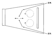
- FIG. 4 is a conceptual diagram showing a state of rectification in the intake device of the present embodiment.
- the rectifying member when the rectifying member is formed in a substantially partial spherical shape that is convex toward the discharge port, the sucked air is introduced along the convex surface, so that vortex is not generated and smooth. To the outlet.
- the distance x from the end of the rectifying member to the discharge port is preferably shorter.
- the shape of the rectifying member may be a substantially egg shape as shown in FIG. 5, a substantially conical shape as shown in FIG. 6, or as shown in FIG. It is conceivable to use a substantially pyramid shape. In any shape, the sucked air is smoothly conveyed to the discharge port along the convex surface of the rectifying member.
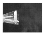
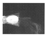
- FIGS. 8a to 8d are photographs taken of the intake device sucking smoke.
- FIG. 8a is a photograph when the rectifying member is configured in a planar shape
- FIG. 8b is a photograph when the rectifying member is configured in a convex shape with the direction in which the fluid flows downward
- FIG. FIG. 8D is a photograph of the rectifying member formed into a substantially partial spherical shape having a convex shape with the direction in which the fluid flows as an upper side
- FIG. It is the photograph at the time of comprising in a substantially egg shape.
- FIGS. 8c and d the smoke lines drawn are clearly shown compared to FIGS. 8a and b. Therefore, it was shown that the rectification member as in the present embodiment prevents the generation of vortices in the vicinity of the discharge port and improves the suction linear velocity.
- ⁇ Embodiment 1 Effect>
- Embodiment 2 the intake device which can attract
- Embodiment 2 the intake device which can attract
- the intake device of the first embodiment when a part of the rectifying member is disposed outside the suction hood, the air introduced along the part does not immediately flow to the discharge port, and part of dust and splashes. Has the problem of splashing around.
- the air intake device of the present embodiment is characterized in that the rectifying member is completely accommodated in the suction hood.
- the intake device of this embodiment includes a main body, an arm, a suction hood, and a rectifying member. Since the main body, the arm, and the suction hood are the same as those described in the first embodiment, the description thereof is omitted.
- the rectifying member is the same as that described in the first embodiment except for the points described below.
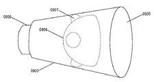
- FIG. 9 is an enlarged view of a suction hood portion in the intake device of the present embodiment.
- the “rectifying member” (0904) in the present embodiment is disposed so as to be completely accommodated in the suction hood.
- straightening member will flow to a discharge port, and the suction efficiency of dust or a droplet improves.
- Embodiment 2 Effect>
- Embodiment 3 >> ⁇ Embodiment 3: Overview>
- the intake device of the present embodiment is characterized in that a part of the flow regulating member is provided so as to protrude outside the suction hood, and the portion provided so as to protrude is convex with the direction in which the fluid flows upward.
- a part of the flow regulating member is provided so as to protrude outside the suction hood, and the portion provided so as to protrude is convex with the direction in which the fluid flows upward.
- the intake device of this embodiment includes a main body, an arm, a suction hood, and a rectifying member. Since the main body, the arm, and the suction hood are the same as those described in the first embodiment, the description thereof is omitted.
- the rectifying member is the same as that described in the first embodiment except for the points described below.
- FIG. 10 is an enlarged view of a suction hood portion in the intake device of the present embodiment.
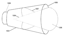
- the “rectifying member” (1004) in the present embodiment is provided so as to protrude beyond the suction hood, and the protruding rectifying member portion (1008) has an upward direction in which the fluid flows. As a convex shape.
- the rectifying member portion provided outside the suction hood has a convex shape, the air introduced along the rectifying member portion is smoothly carried into the suction hood, and the dust And splashes do not scatter around. Further, when the rectifying member is configured as shown in FIG. 10, the distance from the end of the rectifying member to the discharge port is shortened, and the generation of vortices can be more effectively prevented. ⁇ Embodiment 3: Effect>
- an intake device capable of efficiently sucking dust and splashes scattered over a wide range.
- Conceptual diagram showing the state of rectification in the prior art The conceptual diagram which shows the mode of the rectification
- the figure which shows an example of the shape of a baffle member The figure which shows an example of the shape of a baffle member
- the figure which shows an example of the shape of a baffle member The figure which shows an example of the shape of a baffle member
- a photograph of the air intake device sucking smoke when the flow straightening member is configured to be a convex, partially spherical shape with the fluid flow direction on the top
Landscapes
- Health & Medical Sciences (AREA)
- Life Sciences & Earth Sciences (AREA)
- Animal Behavior & Ethology (AREA)
- General Health & Medical Sciences (AREA)
- Public Health (AREA)
- Veterinary Medicine (AREA)
- Dentistry (AREA)
- Epidemiology (AREA)
- Ventilation (AREA)
Abstract
【課題】 従来技術においては、口腔外吸気装置の吸引力が弱かったり、吸引フードと口腔との間の距離や位置関係が適切でなかったりすることによって、診療中に口腔外へ飛散する歯や補修物の削りかす、唾液、細菌、血液、洗浄水、歯面清掃剤等の粉塵や飛沫を完全に吸引できないという問題点があった。 【解決方法】 本発明は、吸引力を向上させるために、吸引フードの開口部分に流体の流れてゆく向きを上側として凸形状の整流部材を備えた、広範囲に飛散する粉塵や飛沫を効率良く吸引可能な吸気装置を提供する。
Description
本発明は、吸引フードの開口部分に整流部材を備えた吸気装置に関する。
歯科治療においては、診療中に口腔外へ飛散する歯や補修物の削りかす、唾液、細菌、血液、洗浄水、歯面清掃剤等の粉塵や飛沫を患者の口元で吸引し、患者や歯科医療従事者の健康を守ると同時に診療室内を清潔に保つために、口腔外吸気装置が利用されている。
しかしながら、上記従来技術においては、吸引力が弱かったり、吸引フードと口腔との間の距離や位置関係が適切でなかったりすることによって、これらの粉塵や飛沫を完全に吸引できないという問題点があった。
そこで、本発明は、吸引力を向上させるために、吸引フードの開口部分に整流部材を備えた吸気装置を提供することを課題とする。
本発明が提供する吸気装置は、具体的には、次のような吸気装置である。
第1発明では、流体の流れてゆく向きを上側として凸形状の整流部材を備えた吸引フードを有する吸気装置を提供する。
第2発明では、第1発明を基本として、整流部材が略卵型、略円錐型、略角錐型、略部分球型から選ばれるいずれか一の型である吸気装置を提供する。
第3発明では、第1発明又は第2発明のいずれか一を基本として、吸引フード内面がメガフォン内面形状である吸気装置を提供する。
第4発明では、第1発明から第3発明のいずれか一を基本として、整流部材が吸引フード内に完全に収容される吸気装置を提供する。
第5発明では、第1発明から第3発明のいずれか一を基本として、整流部材が吸引フード外にもはみだして設けられる吸気装置を提供する。
第6発明では、第5発明を基本として、吸引フード外にはみだして設けられる整流部材部分が流体の流れてくる向きを上側として凸形状の整流部材部分である吸気装置を提供する。
本発明によれば、広範囲に飛散する粉塵や飛沫を効率良く吸引可能な吸気装置を提供できる。
以下に、図を用いて本発明の実施の形態を説明する。なお、本発明はこれらの実施の形態に何ら限定されるものではなく、その要旨を逸脱しない範囲において、種々なる態様で実施しうる。なお、実施形態1は、主に請求項1ないし3について説明する。実施形態2は、主に請求項4について説明する。実施形態3は、主に請求項5及び6について説明する。
≪実施形態1≫
<実施形態1:概要>
≪実施形態1≫
<実施形態1:概要>
本実施形態の吸気装置は、吸引フードに、流体の流れてゆく向きを上側として凸形状の整流部材が備えられていることを特徴とする。
<実施形態1:構成>
<実施形態1:構成>
本実施形態の吸気装置は、整流部材を備えた吸引フードを有し、他に、本体やアーム等を有していても良い。図1を参照する。図1は、本実施形態の吸気装置の全体を示す概念図である。
「本体」(0101)には、吸引を行うために負圧を発生させる機構が備えられている。具体的には、電源を入れることでモーターが回転を開始し、モーターの回転軸に接続された部材が回転して本体内部に負圧を発生させる、といった具合である。
「アーム」(0102)とは、本体に接続される部品であって、後に詳述する吸引フードを支持する機能を有する。図1に示すように、アームにはいくつかの関節が備えられていることが望ましい。このように構成することによって、アームの先端に接続される吸引フードの位置を容易に調整することが可能となる。
「吸引フード」(0103)とは、アームの先端に接続される部品であって、粉塵や飛沫を捕集する機能を有する。ここで、図2を参照する。図2は、本実施形態の吸気装置における吸引フード部分を拡大した図である。なお、点線で描かれた部分は、吸引フード内部の構造を示している。図2に示すように、本実施形態においては、吸引フード内面がメガフォン内面形状となるよう構成されている。このように構成することによって、捕集空間がより広くなり、広範囲に飛散する粉塵や飛沫を効率良く吸引することが可能となる。
「整流部材」(0204)は、吸引フード内部に配置される部品であって、吸引口(0205)から吸引された空気を空洞部内に導入する機能を有する。本実施形態の整流部材は、流体の流れてゆく向きを上側として凸形状であることを特徴とする。流体の流れてゆく向きを上側として凸形状とは、図2に示すように、排出口(0206)に向かって凸形状であることを意味する。整流部材は、支持台(0207)によって吸引フード内部に固定されている。
図3を参照する。図3は、従来技術における整流の様子を示す概念図である。図3に示すように、従来技術におけるような板状の整流部材では、渦の発生を十分に防止することができなかった。
図4を参照する。図4は、本実施形態の吸気装置における整流の様子を示す概念図である。図4に示すように、整流部材を排出口に向かって凸形状の略部分球型に構成した場合、吸引された空気は凸面に沿って導入されるため、渦を発生させることがなく、スムーズに排出口まで運ばれる。なお、渦の発生しうる捕集空間の体積を最小化するために、整流部材の端から排出口までの距離xは、短い方がより望ましい。
なお、整流部材の形状としては、略部分球型以外にも、図5に示すように略卵型とすることや、図6に示すように略円錐型とすることや、図7に示すように略角錐型とすることが考えられる。いずれの形状においても、吸引された空気は整流部材の凸面に沿ってスムーズに排出口まで運ばれることとなる。
図8aないしdは、吸気装置が煙を吸引する様子を撮影した写真である。図8aは、整流部材を平面状に構成した場合の写真であり、図8bは、整流部材を、流体の流れてゆく向きを下側として凸形状に構成した場合の写真であり、図8cは、整流部材を、流体の流れてゆく向きを上側として凸形状の略部分球型に構成した場合の写真であり、図8dは、整流部材を、流体の流れてゆく向きを上側として凸形状の略卵型に構成した場合の写真である。図8c及びdには、図8a及びbと比較して、吸引される煙の筋が明瞭に表れている。したがって、本実施形態のように整流部材を構成することで、排出口付近における渦の発生が防止され、吸引線速度が向上することが示された。
<実施形態1:効果>
<実施形態1:効果>
本発明によれば、広範囲に飛散する粉塵や飛沫を効率良く吸引可能な吸気装置を提供できる。
<<実施形態2>>
<実施形態2:概要>
<<実施形態2>>
<実施形態2:概要>
実施形態1の吸気装置においては、整流部材の一部が吸引フードの外に配置されている場合、当該部分に沿って導入された空気は直ちに排出口まで流れていかず、粉塵や飛沫の一部が周辺に飛び散るという問題点がある。
本実施形態の吸気装置は、かかる問題点を解決するために、整流部材を吸引フード内に完全に収容したことを特徴とする。
<実施形態2:構成>
<実施形態2:構成>
本実施形態の吸気装置は、本体と、アームと、吸引フードと、整流部材と、からなる。本体、アーム、及び吸引フードに関しては、実施形態1で説明したところと同様であるので、説明を省略する。また、整流部材に関しては、以下に述べる点を除いて、実施形態1で説明したところと同様である。
図9を参照する。図9は、本実施形態の吸気装置における吸引フード部分を拡大した図である。図9に示すように、本実施形態における「整流部材」(0904)は、吸引フード内に完全に収容されるように配置されている。このように構成することによって、整流部材の凸面に沿って導入された空気が全て排出口まで流れてゆくこととなり、粉塵や飛沫の吸引効率が向上する。
<実施形態2:効果>
<実施形態2:効果>
本発明によれば、広範囲に飛散する粉塵や飛沫を効率良く吸引可能な吸気装置を提供できる。
<<実施形態3>>
<実施形態3:概要>
<<実施形態3>>
<実施形態3:概要>
本実施形態の吸気装置は、整流部材の一部が吸引フード外にはみだして設けられ、かつ、はみだして設けられる部分は流体の流れてくる向きを上側として凸形状であることを特徴とする。
<実施形態3:構成>
<実施形態3:構成>
本実施形態の吸気装置は、本体と、アームと、吸引フードと、整流部材と、からなる。本体、アーム、及び吸引フードに関しては、実施形態1で説明したところと同様であるので、説明を省略する。また、整流部材に関しては、以下に述べる点を除いて、実施形態1で説明したところと同様である。
ここで、図10を参照する。図10は、本実施形態の吸気装置における吸引フード部分を拡大した図である。図10に示すように、本実施形態における「整流部材」(1004)は、吸引フード外にもはみだして設けられ、はみだして設けられる整流部材部分(1008)は、流体の流れてくる向きを上側として凸形状となるよう構成されている。
本実施形態の吸気装置においては、吸引フード外にはみだして設けられた整流部材部分が凸形状であるため、当該整流部材部分に沿って導入された空気がスムーズに吸引フード内に運ばれ、粉塵や飛沫が周辺に飛び散ることがない。また、整流部材を図10に示すような形状に構成した場合、整流部材の端から排出口までの距離が短くなり、渦の発生をより効果的に防止できる。
<実施形態3:効果>
<実施形態3:効果>
本発明によれば、広範囲に飛散する粉塵や飛沫を効率良く吸引可能な吸気装置を提供できる。
0101 本体
0102 アーム
0103 吸引フード
0204 整流部材
0205 吸引口
0206 排出口
0207 支持台
1008 はみだして設けられる整流部材部分
0102 アーム
0103 吸引フード
0204 整流部材
0205 吸引口
0206 排出口
0207 支持台
1008 はみだして設けられる整流部材部分
Claims (6)
- 流体の流れてゆく向きを上側として凸形状の整流部材を備えた吸引フードを有する吸気装置。
- 前記整流部材は略卵型、略円錐型、略角錐型、略部分球型から選ばれるいずれか一の型である請求項1に記載の吸気装置。
- 前記吸引フード内面は、メガフォン内面形状である請求項1又は2に記載の吸気装置。
- 前記整流部材は、前記吸引フード内に完全に収容される請求項1から3のいずれか一に記載の吸気装置。
- 前記整流部材は、前記吸引フード外にもはみだして設けられる請求項1から3のいずれか一に記載の吸気装置。
- 前記吸引フード外にはみだして設けられる整流部材部分は、流体の流れてくる向きを上側として凸形状の整流部材部分である請求項5に記載の吸気装置。
Priority Applications (2)
| Application Number | Priority Date | Filing Date | Title |
|---|---|---|---|
| US14/779,745 US9888989B2 (en) | 2013-04-18 | 2014-04-17 | Intake device |
| EP14786090.2A EP2987462B1 (en) | 2013-04-18 | 2014-04-17 | Intake device |
Applications Claiming Priority (2)
| Application Number | Priority Date | Filing Date | Title |
|---|---|---|---|
| JP2013-087134 | 2013-04-18 | ||
| JP2013087134A JP6332841B2 (ja) | 2013-04-18 | 2013-04-18 | 吸気装置 |
Publications (1)
| Publication Number | Publication Date |
|---|---|
| WO2014171555A1 true WO2014171555A1 (ja) | 2014-10-23 |
Family
ID=51731487
Family Applications (1)
| Application Number | Title | Priority Date | Filing Date |
|---|---|---|---|
| PCT/JP2014/061502 Ceased WO2014171555A1 (ja) | 2013-04-18 | 2014-04-17 | 吸気装置 |
Country Status (4)
| Country | Link |
|---|---|
| US (1) | US9888989B2 (ja) |
| EP (1) | EP2987462B1 (ja) |
| JP (1) | JP6332841B2 (ja) |
| WO (1) | WO2014171555A1 (ja) |
Families Citing this family (10)
| Publication number | Priority date | Publication date | Assignee | Title |
|---|---|---|---|---|
| TWI517905B (zh) * | 2012-09-08 | 2016-01-21 | 西凱渥資訊處理科技公司 | 於射頻模組製造期間關於漆霧收集之裝置及方法 |
| CN106151107A (zh) * | 2016-08-02 | 2016-11-23 | 南通白云环保工程设备有限公司 | 一种带减速器式集风罩 |
| US10829228B2 (en) | 2017-01-17 | 2020-11-10 | Itt Manufacturing Enterprises, Llc | Fluid straightening connection unit |
| USD942617S1 (en) | 2020-01-08 | 2022-02-01 | Mark George Smith | Dental suction attachment |
| US12440319B2 (en) * | 2020-05-04 | 2025-10-14 | Stoma Ventures, LLC | Disposable dental aerosol device |
| ES1251709Y (es) * | 2020-06-05 | 2020-11-16 | Bonnin Bernardo Gabriel Trigo | Dispositivo de protección |
| WO2021252072A1 (en) * | 2020-06-08 | 2021-12-16 | Perio Dome Inc | Aerosol reduction systems and methods |
| US20210401557A1 (en) * | 2020-06-24 | 2021-12-30 | Shu-Chuan SHEU | Oral medical assist device |
| US11723760B2 (en) * | 2021-08-06 | 2023-08-15 | Gregory Prior | Aerosol deflecting dental shield and containment device |
| WO2026050443A1 (en) * | 2024-08-30 | 2026-03-05 | The Regents Of The University Of Colorado, A Body Corporate | Surgical aerosol mitigation tool |
Citations (4)
| Publication number | Priority date | Publication date | Assignee | Title |
|---|---|---|---|---|
| JPH0938112A (ja) * | 1995-07-26 | 1997-02-10 | Tokyo Giken:Kk | 歯科用吸引フード装置 |
| JP2004033474A (ja) * | 2002-07-03 | 2004-02-05 | Osada Res Inst Ltd | 歯科用呼吸器官保護装置 |
| JP2011122738A (ja) * | 2009-12-08 | 2011-06-23 | Taikisha Ltd | 補助噴出口付き排気器具、及び、その補助噴出口付き排気器具を用いた排気ユニット |
| JP2013096318A (ja) * | 2011-11-01 | 2013-05-20 | Arimi Miyawaki | 整流装置を内蔵した水流コーン体 |
Family Cites Families (25)
| Publication number | Priority date | Publication date | Assignee | Title |
|---|---|---|---|---|
| JPS4996752U (ja) * | 1972-12-08 | 1974-08-21 | ||
| JPS56109536U (ja) * | 1980-01-25 | 1981-08-25 | ||
| USD287402S (en) * | 1983-06-17 | 1986-12-23 | Orsing Ernst L | Nozzle for a suction drainage device for performing surgery in the mouth |
| US4776793A (en) * | 1987-09-17 | 1988-10-11 | Rocca Nina | Dental aspirator |
| USD312872S (en) * | 1987-11-09 | 1990-12-11 | Thomas Mahl | Dental suction head |
| US4865545A (en) * | 1988-07-27 | 1989-09-12 | Rocca Nina | Dental aspirator |
| JPH0725537Y2 (ja) * | 1989-04-03 | 1995-06-07 | 大阪瓦斯株式会社 | 家庭用レンジフード |
| NO971697L (no) * | 1997-04-14 | 1998-10-15 | Vidar Wiik | Anordning til fjerning av gass og partikler i forbindelse med sveising/skjµrebrenning |
| US6186783B1 (en) * | 1997-10-17 | 2001-02-13 | Dentsply Research & Development Corp. | Evacuation hand piece for use during dental procedures |
| DE29900106U1 (de) | 1999-01-07 | 1999-04-08 | Lauer, Oliver, Dipl.-Ing., 54295 Trier | Erfassungshaube, insbesondere für Schweißrauche und Schleifstäube |
| US6308707B1 (en) * | 1999-02-10 | 2001-10-30 | Li-Chow Lu | Vacuum equipment for medical tables |
| JP2000256980A (ja) * | 1999-03-11 | 2000-09-19 | Sumiju Ahlstrom Kk | パルプ処理装置 |
| JP2003514210A (ja) * | 1999-11-05 | 2003-04-15 | デラウェア キャピタル フォーメーション インコーポレイテッド | 煙吸引装置及びアセンブリー |
| DE10347829A1 (de) * | 2003-10-10 | 2005-05-25 | Coltène/Whaledent GmbH + Co. KG | Zweikomponenten-Absaugkanüle |
| US6776710B1 (en) * | 2003-10-24 | 2004-08-17 | Unico, Inc. | Vent structure for slotted outlet with uniform velocity profile |
| US20110262880A1 (en) * | 2004-04-22 | 2011-10-27 | Mccary Charles | Method for filtering and treating dental solid waste |
| US7238023B1 (en) * | 2004-12-14 | 2007-07-03 | Enos Denise A | Saliva ejector or eductor |
| US7625207B2 (en) * | 2006-12-15 | 2009-12-01 | Kimberly-Clark Worldwide, Inc. | Yankauer suction device with sleeve and wiper |
| US8012141B2 (en) * | 2007-03-29 | 2011-09-06 | Wright Clifford A | Suction wand |
| US8460417B2 (en) * | 2008-11-11 | 2013-06-11 | Great Lakes Air Systems, Inc. | Portable air filtration system |
| US8398398B1 (en) * | 2010-02-25 | 2013-03-19 | William L. Barham | Foam pad used with tubular member to vacuum fluids from an oral cavity |
| SE535187C2 (sv) * | 2010-09-10 | 2012-05-15 | Fumex Ab | Ledkonstruktion, ventilationsarm och ventilationssystem |
| JP5627095B2 (ja) | 2010-10-01 | 2014-11-19 | 株式会社東京技研 | 歯科用口腔外バキューム装置 |
| JP2012112311A (ja) * | 2010-11-25 | 2012-06-14 | Toyota Boshoku Corp | エアフィルタ及びエアクリーナ |
| US9872705B2 (en) * | 2013-10-07 | 2018-01-23 | Regentis Biomaterials Ltd. | Treatment of cavities in a human body |
-
2013
- 2013-04-18 JP JP2013087134A patent/JP6332841B2/ja active Active
-
2014
- 2014-04-17 WO PCT/JP2014/061502 patent/WO2014171555A1/ja not_active Ceased
- 2014-04-17 US US14/779,745 patent/US9888989B2/en active Active
- 2014-04-17 EP EP14786090.2A patent/EP2987462B1/en active Active
Patent Citations (4)
| Publication number | Priority date | Publication date | Assignee | Title |
|---|---|---|---|---|
| JPH0938112A (ja) * | 1995-07-26 | 1997-02-10 | Tokyo Giken:Kk | 歯科用吸引フード装置 |
| JP2004033474A (ja) * | 2002-07-03 | 2004-02-05 | Osada Res Inst Ltd | 歯科用呼吸器官保護装置 |
| JP2011122738A (ja) * | 2009-12-08 | 2011-06-23 | Taikisha Ltd | 補助噴出口付き排気器具、及び、その補助噴出口付き排気器具を用いた排気ユニット |
| JP2013096318A (ja) * | 2011-11-01 | 2013-05-20 | Arimi Miyawaki | 整流装置を内蔵した水流コーン体 |
Non-Patent Citations (1)
| Title |
|---|
| See also references of EP2987462A4 * |
Also Published As
| Publication number | Publication date |
|---|---|
| US9888989B2 (en) | 2018-02-13 |
| EP2987462B1 (en) | 2018-06-13 |
| JP6332841B2 (ja) | 2018-05-30 |
| EP2987462A4 (en) | 2017-01-11 |
| US20160100922A1 (en) | 2016-04-14 |
| JP2014210003A (ja) | 2014-11-13 |
| EP2987462A1 (en) | 2016-02-24 |
Similar Documents
| Publication | Publication Date | Title |
|---|---|---|
| JP6332841B2 (ja) | 吸気装置 | |
| CN105050480B (zh) | 用于牙科检查且具有手柄的镜子 | |
| JP5318273B1 (ja) | 歯科口腔外作業用のフード付簡易吸引トレイ | |
| JP6416747B2 (ja) | 歯科用ミラー付吸引路管 | |
| US20220395358A1 (en) | Systems and methods for an evacuator adapter | |
| CN208958069U (zh) | 一种多功能口镜 | |
| CN211985364U (zh) | 一种口腔显微治疗专用防雾口镜 | |
| CN205514990U (zh) | 口腔外抽吸机 | |
| CN212346780U (zh) | 一种带侧枝管道的面罩式强吸吸引器 | |
| US20230380946A1 (en) | Aerosol deflecting dental shield and containment device | |
| CN212699207U (zh) | 一种吸臂结构 | |
| CN209577691U (zh) | 一种笔式医用抽烟装置 | |
| CN111568583A (zh) | 一种口腔生物滤清器 | |
| CN207912788U (zh) | 一种可拆卸设置的吸引臂 | |
| CN113041160A (zh) | 一种介入手术室用呕吐物收集装置 | |
| CN221904153U (zh) | 一种牙科手术弯吸管辅助器 | |
| CN213851190U (zh) | 一种弱吸发生器 | |
| CN219614084U (zh) | 一种强吸用吸唾装置 | |
| CN211723504U (zh) | 一种口腔咬合垫式多孔开口器 | |
| KR200497429Y1 (ko) | 파티클을 흡입하는 소음저감기 | |
| CN214911139U (zh) | 一种便携式一次性负压吸痰器 | |
| JP6139933B2 (ja) | 取り付け部材、吸引用器具、管状部材、および、診療用装置 | |
| CN214908524U (zh) | 一种开口器 | |
| US11786349B1 (en) | Protective devices for managing aerodynamics around dental patients | |
| CN213406380U (zh) | 一种新型双功能可拆卸式吸唾管-牙龈瓣牵拉器 |
Legal Events
| Date | Code | Title | Description |
|---|---|---|---|
| 121 | Ep: the epo has been informed by wipo that ep was designated in this application |
Ref document number: 14786090 Country of ref document: EP Kind code of ref document: A1 |
|
| WWE | Wipo information: entry into national phase |
Ref document number: 2014786090 Country of ref document: EP |
|
| WWE | Wipo information: entry into national phase |
Ref document number: 14779745 Country of ref document: US |
|
| NENP | Non-entry into the national phase |
Ref country code: DE |