WO2014171558A2 - 電動機 - Google Patents
電動機 Download PDFInfo
- Publication number
- WO2014171558A2 WO2014171558A2 PCT/JP2014/065066 JP2014065066W WO2014171558A2 WO 2014171558 A2 WO2014171558 A2 WO 2014171558A2 JP 2014065066 W JP2014065066 W JP 2014065066W WO 2014171558 A2 WO2014171558 A2 WO 2014171558A2
- Authority
- WO
- WIPO (PCT)
- Prior art keywords
- permanent magnet
- rotor core
- flux barrier
- electric motor
- rotor
- Prior art date
- Legal status (The legal status is an assumption and is not a legal conclusion. Google has not performed a legal analysis and makes no representation as to the accuracy of the status listed.)
- Ceased
Links
Images


Classifications
-
- H—ELECTRICITY
- H02—GENERATION; CONVERSION OR DISTRIBUTION OF ELECTRIC POWER
- H02K—DYNAMO-ELECTRIC MACHINES
- H02K1/00—Details of the magnetic circuit
- H02K1/06—Details of the magnetic circuit characterised by the shape, form or construction
- H02K1/22—Rotating parts of the magnetic circuit
- H02K1/27—Rotor cores with permanent magnets
- H02K1/2706—Inner rotors
- H02K1/272—Inner rotors the magnetisation axis of the magnets being perpendicular to the rotor axis
- H02K1/274—Inner rotors the magnetisation axis of the magnets being perpendicular to the rotor axis the rotor consisting of two or more circumferentially positioned magnets
- H02K1/2753—Inner rotors the magnetisation axis of the magnets being perpendicular to the rotor axis the rotor consisting of two or more circumferentially positioned magnets the rotor consisting of magnets or groups of magnets arranged with alternating polarity
- H02K1/276—Magnets embedded in the magnetic core, e.g. interior permanent magnets [IPM]
- H02K1/2766—Magnets embedded in the magnetic core, e.g. interior permanent magnets [IPM] having a flux concentration effect
-
- H—ELECTRICITY
- H02—GENERATION; CONVERSION OR DISTRIBUTION OF ELECTRIC POWER
- H02K—DYNAMO-ELECTRIC MACHINES
- H02K1/00—Details of the magnetic circuit
- H02K1/06—Details of the magnetic circuit characterised by the shape, form or construction
- H02K1/22—Rotating parts of the magnetic circuit
- H02K1/32—Rotating parts of the magnetic circuit with channels or ducts for flow of cooling medium
-
- H—ELECTRICITY
- H02—GENERATION; CONVERSION OR DISTRIBUTION OF ELECTRIC POWER
- H02K—DYNAMO-ELECTRIC MACHINES
- H02K21/00—Synchronous motors having permanent magnets; Synchronous generators having permanent magnets
- H02K21/02—Details
- H02K21/04—Windings on magnets for additional excitation ; Windings and magnets for additional excitation
- H02K21/046—Windings on magnets for additional excitation ; Windings and magnets for additional excitation with rotating permanent magnets and stationary field winding
-
- H—ELECTRICITY
- H02—GENERATION; CONVERSION OR DISTRIBUTION OF ELECTRIC POWER
- H02K—DYNAMO-ELECTRIC MACHINES
- H02K5/00—Casings; Enclosures; Supports
- H02K5/04—Casings or enclosures characterised by the shape, form or construction thereof
- H02K5/20—Casings or enclosures characterised by the shape, form or construction thereof with channels or ducts for flow of cooling medium
- H02K5/203—Casings or enclosures characterised by the shape, form or construction thereof with channels or ducts for flow of cooling medium specially adapted for liquids, e.g. cooling jackets
-
- H—ELECTRICITY
- H02—GENERATION; CONVERSION OR DISTRIBUTION OF ELECTRIC POWER
- H02K—DYNAMO-ELECTRIC MACHINES
- H02K9/00—Arrangements for cooling or ventilating
- H02K9/19—Arrangements for cooling or ventilating for machines with closed casing and closed-circuit cooling using a liquid cooling medium, e.g. oil
Definitions
- the present invention relates to an electric motor, and more particularly to an improvement in a fixing structure of a permanent magnet used in a rotor of an embedded permanent magnet type synchronous motor.
- a permanent magnet is inserted into a plurality of holes provided in a rotor core, and an adhesive is applied to a gap formed between the outer surface of the permanent magnet and the inner surface of the hole. It is known to fill and thus fix the permanent magnet to the rotor core (see, for example, Patent Documents 1 and 2).
- an adhesive is filled in a gap formed at a position on the inner peripheral side of the rotor core among the gaps between the hole and the permanent magnet.
- the permanent magnet is pushed to the outer peripheral side of the rotor core and brought into contact with the inner surface of the hole located on the outer peripheral side of the rotor core. For this reason, no gap is formed on the outer peripheral side, and the adhesive does not rotate. Therefore, the adhesive is mainly filled in the gap formed at the position on the inner peripheral side, but if a situation where the gap is not sufficiently filled occurs, the fixing strength of the permanent magnet is remarkably lowered. When a large centrifugal force generated during high load and high rotation is repeatedly applied, the permanent magnet may fall off in the hole.
- An object of the present invention is to provide an electric motor that can easily perform adhesive filling work and can reliably hold a permanent magnet.
- An electric motor includes an annular stator mounted in a housing, a rotor disposed in the stator and rotatably supported by the housing, and a plurality of permanent magnets in a rotor core of the rotor.
- the rotor core is provided with embedded holes into which the permanent magnets are fitted, and the permanent magnets in the embedded holes are diagonally positioned in the axial direction of the rotor core.
- a continuous filling hole is formed along the surface.
- the rotor core is provided with a flux barrier by an end portion of the embedded hole, and the flux barrier is an oil passage through which cooling oil flows.
- the rotor core is provided with a flux barrier by an end portion of the embedded hole, and the flux barrier is provided with a support portion for supporting the permanent magnet.
- the support portion is provided on the opposite side of the filling hole across the corner portion of the permanent magnet having a prismatic shape.
- An electric motor includes an annular stator mounted in a housing, and a rotor disposed in the stator and rotatably supported by the housing.
- the rotor core of the rotor has a plurality of rectangular cross sections.
- a continuous filling hole is formed along the axial direction of the rotor core, and the inner flux barrier is an oil passage through which cooling oil flows, and the outer peripheral flux barrier and the inner flux
- the barrier is provided with a support portion that abuts a part of the end face of the permanent magnet and supports the permanent magnet, and the support portion sandwiches the corner portion of the permanent magnet having a prismatic shape, and fills the hole. It is characterized by being provided on the opposite side.
- the permanent magnet is bonded to the rotor core only at the portions corresponding to the two diagonal positions, the filling amount of the adhesive or the like can be greatly reduced, and the filling operation can be performed quickly and easily.
- the permanent magnet since the permanent magnet is fitted into the embedded hole, even if it is fixed by adhesion at only two locations, it can sufficiently resist the centrifugal force when the rotor rotates, and the permanent magnet is securely held in the embedded hole. It is possible to leave.
- the flux barrier since the flux barrier is not filled with the adhesive, the flux barrier can be reliably secured as an oil passage for circulating the cooling oil, and the permanent magnet and the rotor core can be cooled well.
- the support portion since the support portion is provided on the flux barrier, the permanent magnet fitted in the embedded hole can be more reliably fixed, and the permanent magnet can be prevented from falling off in the embedded hole.
- the support portion since the support portion is provided on the side opposite to the adhesive filling hole across the corner portion of the permanent magnet, the filling hole and the support portion can be sufficiently large and fixed at positions where they do not interfere with each other. Strength and durability can be improved.
- the effects of the first to fourth aspects can be obtained similarly.
- a sectional view showing the whole electric motor concerning one embodiment of the present invention The figure which shows the rotor core of the said electric motor.
- the enlarged view which expands and shows the principal part of the said rotor core.
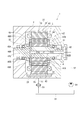
- FIG. 1 is a cross-sectional view showing the entire electric motor 1 of the present embodiment.
- FIG. 2 is a view showing the rotor core 41 of the electric motor 1.
- an electric motor 1 includes an annular stator 3 mounted in a housing 2 and a rotor 4 that is disposed in the stator 3 and is rotatably supported in the housing 2.
- Such an electric motor 1 is configured as an embedded permanent magnet type synchronous motor in which a permanent magnet 43 is embedded in a rotor core 41 of a rotor 4.
- the stator 3 includes a stator core 31 formed by laminating a large number of electromagnetic steel plates along the axial direction.
- the stator core 31 includes an outer peripheral yoke 32 continuous in the circumferential direction and a plurality of teeth 33 protruding from the yoke 32 toward the central rotor 4 side.
- the plurality of teeth 33 are provided at equal intervals along the circumferential direction of the yoke 32.
- An electromagnetic coil 34 is wound around such a tooth 33.
- the rotor 4 includes an annular rotor core 41 configured by laminating a large number of electromagnetic steel plates along the axial direction in the same manner as the stator core 31, and a rotor shaft 42 inserted through an insertion hole 41A provided in the center of the rotor core 41. And a total of 16 prismatic permanent magnets 43 fitted into the embedded holes 41B (see FIG. 2) of the rotor core 41.
- the embedded hole 41B of the rotor core 41 is provided in a V shape so as to be symmetric when viewed from the axial center side.
- a pair of such embedded holes 41B is taken as one set, and one magnetic pole is formed by a pair of permanent magnets 43 embedded in the set of embedded holes 41B. That is, the number of poles of the rotor 4 of this embodiment is eight. The polarities of adjacent magnetic poles are different from each other.
- the magnetic poles are formed at equal intervals along the circumferential direction of the rotor core 41.
- one end in the longitudinal direction of the embedded hole 41B whose opening shape is a long hole is a flux barrier 41C made of a gap.
- one end surface 43B (see FIG. 3) is positioned on the flux barrier 41C.
- the other end in the longitudinal direction of the embedded hole 41B is a similar flux barrier 41D on which the other end face 43B of the permanent magnet 43 is located. That is, a pair of side surfaces 43A (see FIG. 3) on the long side of the permanent magnet 43 are in contact with the inner surface of the embedded hole 41B except for a part of an end surface 43B that comes into contact with support portions 71 and 72 described later. is doing.
- the flux barrier 41 ⁇ / b> C located on the outer peripheral side of the rotor core 41 is provided in order to reduce the leakage magnetic flux from the permanent magnet 43.
- the flux barrier 41D located on the inner side far from the outer peripheral surface of the rotor core 41 is provided to reduce leakage magnetic flux from the permanent magnet 43 and to constitute a part of a cooling structure described later.
- a side bridge 44 is provided between the flux barrier 41C and the outer peripheral surface of the rotor core 41, and a center bridge 45 is provided between the flux barriers 41D adjacent to each other on the center side of the magnetic pole. The side bridge 44 will be described later.
- the annular end plates 46 and 47 are attached to both sides of the rotor core 41 in the axial direction.
- the end plate 46 attached to the rotor core 41 communicates the portion corresponding to the flux barrier 41D of the rotor core 41 and the rotor shaft 42 side.
- a path 46A is provided along the radial direction.
- a discharge hole 46B opened in the housing 2 is provided at the end of the oil passage 46A.
- the other end plate 47 is provided with a discharge opening 47A at a position corresponding to the flux barrier 41D, and the flux barrier 41D communicates with the inside of the housing 2.
- the horizontal electric motor 1 in which the axial direction of the rotor shaft 42 is substantially horizontal is described.
- the vertical electric motor in which the axial direction of the rotor shaft is substantially vertical is described.
- An electric motor may be used.
- the discharge hole 46B may be omitted.
- an oil passage 42B that opens on the opposite side to the output part 42A and extends toward the output part 42A along the axial direction.
- the end portion on the output portion 42A side of the oil passage 42B communicates with the oil passage 42C penetrating in the radial direction.
- the oil passage 42 ⁇ / b> C communicates with the oil passage 46 ⁇ / b> A of the end plate 46.
- a rare earth permanent magnet such as neodymium or dysprosium is preferably used.
- a permanent magnet 43 is fixed by an adhesive in a state of being fitted in the embedded hole 41B of the rotor core 41.
- the fixing structure of the permanent magnet 43 will be described later.
- the supply flow path 52 from the cooling oil tank 51 is connected to the opening side of the oil path 42B provided in the rotor shaft 42 of the electric motor 1.
- a drain passage 53 to the cooling oil tank 51 is connected to a drain opening 2 ⁇ / b> A provided in the bottom portion of the housing 2 constituting the electric motor 1.
- the supply passage 52 is provided with a hydraulic pump 54, and the drain passage 53 is provided with an oil cooler 55.
- the cooling oil sucked up by the hydraulic pump 54 from the cooling oil tank 51 enters the oil passage 42B of the rotor shaft 42, flows in the oil passage 42B from one end side to the other end side along the axial direction, and the other end. It flows into the oil passage 46A of the end plate 46 through the radial oil passage 42C provided on the side.
- a portion of the cooling oil that has entered the oil passage 46A is injected into the housing 2 from the discharge hole 46B, thereby cooling the rotor core 41 and the electromagnetic coil 34. Further, the other cooling oil that has entered the oil passage 46A enters the flux barrier 41D of the rotor core 41 and cools the rotor core 41 and the permanent magnet 43 by flowing in the flux barrier 41D along the axial direction. The cooling oil that has finished flowing through the flux barrier 41D is injected into the housing 2 from the discharge opening 47A of the end plate 47, and also cools the rotor core 41 and the electromagnetic coil 34.
- the cooling oil sprayed from the discharge hole 46B and the discharge opening 47A cools the rotor core 41 and the electromagnetic coil 34, and cools the bearings 21 and 22 that support the rotation of the rotor shaft 42.
- the cooling oil that has cooled them is dropped into the housing 2 and collected in the oil reservoir 23 at the bottom.
- the collected cooling oil flows from the oil reservoir 23 through the drain opening 2 ⁇ / b> A through the drain passage 53, is cooled by the oil cooler 55, and then returns to the cooling oil tank 51.
- FIG. 3 is an enlarged view showing a main part of the rotor core 41 in an enlarged manner.
- two adjacent poles are shown.
- the outer peripheral surface of the rotor core 41 is provided with a first recess 61 and a second recess 62 that are recessed inward in the vicinity of the flux barrier 41 ⁇ / b> C located near the outer periphery.
- the first recesses 61 are provided at positions on the outer side in the circumferential direction with respect to the center of the magnetic pole
- the second recesses 62 are provided at positions on the inner side in the circumferential direction with respect to the center of the magnetic pole.
- interval of the circumferential direction of the 1st recessed part 61 and the 2nd recessed part 62 is a magnitude
- the side bridge 44 has a substantially uniform thickness (a radial thickness) in the circumferential direction of the rotor core 41 in relation to the opening shape of the flux barrier 41 ⁇ / b> C, and on the outer side in the radial direction of the rotor core 41. It is formed in an arch shape curved so as to protrude. That is, the first recess 61 and the second recess 62 are provided on the base end side of the arched side bridge 44.
- the curvature radius of the side bridge 44 is smaller than the radius of the outer periphery of the rotor core 41.
- stress concentration occurs due to the centrifugal force accompanying the rotation of the rotor 4, but the places where the side bridges 44 occur are near both ends in the circumferential direction and the center in the circumferential direction.
- stress is generated by being dispersed at three locations, that is, the bottom portions of the first recess portion 61 and the second recess portion 62 and the inner surface side portion of the side bridge 44 (flux barrier 41C). Therefore, stress concentration does not occur at one point, the stress generated at each location can be reduced, and durability is improved.
- the second recess 62 can function as a portion that reduces torque pulsation, iron loss, magnetic flux harmonics, or cogging torque, The characteristics of the electric motor 1 can be improved.
- the support portion 72 on the flux barrier 41D side is provided at the base end portion on the outer side of the center bridge 45, and the other end surface 43B of the permanent magnet 43 is on the edge closer to the outer peripheral surface of the rotor core 41. It is in contact.
- the permanent magnet 43 is supported by the rotor core 41 at two diagonal positions on the opposite short side edge.
- the contact width at which the support portions 71 and 72 are in contact with the end surface 43B of the permanent magnet 43 is approximately 1/5 (5 minutes) with respect to the entire width on the short side of the permanent magnet 43 provided with the end surface 43B. It is desirable to be shorter than 1). By being shorter than 1/5, the leakage magnetic flux from the end face 43B can be reduced. Further, the contact portion of the support portions 71 and 72 on the end surface 43 ⁇ / b> B may be separated from the end portion in the width direction of the end surface 43 ⁇ / b> B that is a corner portion of the permanent magnet 43.
- the extended part 73 is provided in the position on the opposite side to the support parts 71 and 72 across the corner part of the permanent magnet 43.
- the extended portion 73 is provided by extending a part of the embedded hole 41 ⁇ / b> B in order to form a slight gap with the side surface 43 ⁇ / b> A of the permanent magnet 43.
- the extension part 73 is also provided in all the steel plates 7 to be laminated.
- the laminated steel plates 7 all have the same shape, and by aligning each, an embedded hole 41B communicating with the lamination direction (same as the axial direction of the rotor core 41) is formed, and the permanent magnet 43 is formed in the embedded hole 41B. Can be incorporated.
- the filling holes 48 penetrating the rotor core 41 along the axial direction are formed in two locations at different diagonal positions of the permanent magnet 43 in the embedded hole 41B by all the extended portions 73 communicating in the stacking direction. Is done. That is, such a filling hole 48 is formed between the permanent magnet 43 and the extended portion 73 in a state where the permanent magnet 43 is incorporated in the embedded hole 41B.
- a resin material such as a molding material may be used as the adhesive.
- the permanent magnet 43 is fitted in the embedded hole 41B, and the side surfaces 43A on both sides of the permanent magnet 43 are in contact with the inner surface of the embedded hole 41B. Therefore, the permanent magnet 43 can be reliably held in the embedded hole 41B with at least an adhesive filling amount.
- the present invention is not limited to the above-described embodiments, and modifications, improvements, and the like within the scope that can achieve the object of the present invention are included in the present invention.
- the filling hole 48 is formed along the axial direction of the rotor core 41.
- a communication portion that communicates the filling hole 48 with the flux barriers 41C and 41D may be further provided. In such a configuration, the air in the filling hole 48 can be extracted through the communication portion, and the filling hole 48 can be easily filled with the adhesive.
- an adhesive filling needle can be inserted into the cross section of the filling hole 48 formed by the expansion portion 73. It may be provided as large as possible. Then, after inserting such a needle to the back side of the filling hole 48, the adhesive is filled through the needle while returning from the back side to the front side.
- the adhesive in a pre-process in which the end plates 46 and 47 are provided on the rotor core 41, that is, in a stage where the end of the filling hole 48 is open.
- the end plates 46 and 47 are provided in the rotor core 41, for example, by providing a communication hole in the end plate 46 in advance for communicating the filling hole 48 and the outside. It is also possible to configure such that the air vent is removed when the adhesive is filled through such a communication hole.
- the first and second recesses 61 and 62 are provided on the outer peripheral surface of the rotor core 41.
- the second recess 62 that functions to improve the characteristics of the generator 1 is provided. Even when the concave portion 61 is omitted or when both the first and second concave portions 61 and 62 are absent, the present invention includes the present invention.
- the present invention is used for vehicles such as an electric vehicle, a hybrid vehicle, an electric construction machine, and a hybrid construction machine, and can be preferably used as an electric motor for running these construction machines.
- SYMBOLS 1 Electric motor, 2 ... Housing, 3 ... Stator, 4 ... Rotor, 41 ... Rotor core, 41B ... Embedded hole, 41C, 41D ... Flux barrier, 43 ... Permanent magnet, 48 ... Filling hole, 71, 72 ... Support part.
Landscapes
- Engineering & Computer Science (AREA)
- Power Engineering (AREA)
- Permanent Field Magnets Of Synchronous Machinery (AREA)
- Iron Core Of Rotating Electric Machines (AREA)
Abstract
ハウジング内に装着された環状のステータと、ステータ内に配置されてハウジングに回転可能に支持されたロータとを備えるとともに、ロータのロータコア(41)に複数の永久磁石(43)が埋め込まれている電動機であって、ロータコア(41)には、永久磁石(43)が嵌合される埋込孔(41B)が設けられ、埋込孔(41B)における永久磁石(43)の対角位置には、ロータコア(41)の軸方向に沿って連続した充填孔(48)が形成されている。
Description
本発明は、電動機に係り、特に埋込永久磁石型同期電動機のロータに用いられる永久磁石の固定構造の改良に関する。
従来、埋込永久磁石型同期電動機のロータでは、ロータコアに設けられた複数の穴部内に永久磁石を挿入し、永久磁石の外表面と穴部内面との間に形成される隙間に接着剤を充填し、よって永久磁石をロータコアに固定することが知られている(例えば、特許文献1,2参照)。
しかし、従来では、永久磁石の外表面と穴部内面との間の広い範囲に接着剤を充填するため、充填作業に手間がかかるという問題がある。特に特許文献1では、穴部に連続して設けられたフラックスバリアまでもが接着剤で満たされており、充填作業に余計に時間がかかって作業性が悪い。
しかも、従来では、穴部と永久磁石との隙間の中でも、ロータコアの内周側の位置に形成される隙間に接着剤を充填している。こうすることで、永久磁石をロータコアの外周側に押しやり、ロータコアの外周側に位置する穴部内面に当接させている。このため、外周側では隙間が形成されず、接着剤が回っていない。従って、接着剤が内周側の位置に形成される隙間に主に充填されることとなるが、この隙間に十分に充填されていない事態が生じると、永久磁石の固定強度が格段に低下し、高負荷、高回転時に生じる大きな遠心力が繰り返し作用した場合に、永久磁石が穴部内で脱落する可能性がある。
また、従来においては、接着剤を圧送して充填する構成であるため、圧送用のポンプ等が必要になるなど、設備が高価になるという問題がある。
さらに、特許文献1,2にあっては、永久磁石やロータコアの冷却に関しては一切触れられておらず、冷却不足を招く可能性がある。
さらに、特許文献1,2にあっては、永久磁石やロータコアの冷却に関しては一切触れられておらず、冷却不足を招く可能性がある。
本発明の目的は、接着剤の充填作業を容易にでき、かつ永久磁石を確実に保持できる電動機を提供することにある。
第1発明に係る電動機は、ハウジング内に装着された環状のステータと、前記ステータ内に配置されて前記ハウジングに回転可能に支持されたロータとを備えるとともに、前記ロータのロータコアに複数の永久磁石が埋め込まれている電動機であって、前記ロータコアには、前記永久磁石が嵌合される埋込孔が設けられ、前記埋込孔における前記永久磁石の対角位置には、前記ロータコアの軸方向に沿って連続した充填孔が形成されることを特徴とする。
第2発明に係る電動機では、前記ロータコアには、前記埋込孔の端部によりフラックスバリアが設けられ、前記フラックスバリアは、冷却油が流通する油路になっていることが望ましい。
第3発明に係る電動機では、前記ロータコアには、前記埋込孔の端部によりフラックスバリアが設けられ、前記フラックスバリアには、前記永久磁石を支持する支持部が設けられることが望ましい。
第4発明に係る電動機では、前記支持部は、角柱状とされた前記永久磁石の角部を挟んで前記充填孔とは反対側に設けられることが望ましい。
第5発明に係る電動機は、ハウジング内に装着された環状のステータと、前記ステータ内に配置されて前記ハウジングに回転可能に支持されたロータとを備えるとともに、前記ロータのロータコアに複数の断面矩形状の永久磁石が埋め込まれている電動機であって、前記ロータの軸中心から見てV字形状に配置された一対の前記永久磁石により1つの磁極が形成され、前記ロータコアには、前記永久磁石が嵌合される埋込孔と、前記埋込孔の一方の端部により形成され、かつ前記ロータコアの外周寄りに位置した外周側のフラックスバリアと、前記埋込孔の他方の端部により形成され、かつ前記外周側のフラックスバリアよりも内方側に位置した内方側のフラックスバリアとが設けられ、前記埋込孔における前記永久磁石の対角位置には、前記ロータコアの軸方向に沿って連続した充填孔が形成され、前記内方側のフラックスバリアは、冷却油が流通する油路になっており、前記外周側のフラックスバリアおよび前記内方側のフラックスバリアには、前記永久磁石の端面の一部と当接して該永久磁石を支持する支持部が設けられ、前記支持部は、角柱状とされた前記永久磁石の角部を挟んで前記充填孔とは反対側に設けられることを特徴とする。
第1発明によれば、永久磁石をその対角の2箇所に対応した部分のみでロータコアに接着するため、接着剤等の充填量を大幅に少なくでき、充填作業を迅速かつ容易にできる。また、永久磁石を埋込孔に嵌合させるので、2箇所のみの接着による固定であっても、ロータ回転時の遠心力に十分に対抗でき、永久磁石を埋込穴内に確実に保持させておくことが可能である。
第2発明によれば、フラックスバリア内が接着剤で満たされることがないから、そのフラックスバリアを冷却油流通用の油路として確実に確保でき、永久磁石やロータコアを良好に冷却できる。
第3発明によれば、フラックスバリアに支持部を設けるので、埋込穴内に嵌合された永久磁石をより確実に固定でき、埋込孔内での永久磁石の脱落をより確実に防止できる。
第4発明によれば、支持部を永久磁石の角部を挟んで接着剤の充填孔とは反対側に設けるため、充填孔および支持部を互いに干渉されない位置で十分な大きさにでき、固定強度や耐久性を向上させることができる。
第5発明によれば、第1発明ないし第4発明での作用効果を同様に得ることができる。
第3発明によれば、フラックスバリアに支持部を設けるので、埋込穴内に嵌合された永久磁石をより確実に固定でき、埋込孔内での永久磁石の脱落をより確実に防止できる。
第4発明によれば、支持部を永久磁石の角部を挟んで接着剤の充填孔とは反対側に設けるため、充填孔および支持部を互いに干渉されない位置で十分な大きさにでき、固定強度や耐久性を向上させることができる。
第5発明によれば、第1発明ないし第4発明での作用効果を同様に得ることができる。
〔電動機の全体構成〕
以下、本発明の一実施形態を図面に基づいて説明する。
図1は、本実施形態の電動機1の全体を示す断面図である。図2は、電動機1のロータコア41を示す図である。
以下、本発明の一実施形態を図面に基づいて説明する。
図1は、本実施形態の電動機1の全体を示す断面図である。図2は、電動機1のロータコア41を示す図である。
図1において、電動機1は、ハウジング2の内部に装着された環状のステータ3と、ステータ3内に配置されるとともに、ハウジング2内で回転可能に支持されたロータ4とを備える。このような電動機1は、ロータ4のロータコア41内に永久磁石43が埋め込まれた埋込永久磁石型同期電動機として構成されている。
〔ステータ〕
ステータ3は、図には明示していないが、電磁鋼板を軸方向に沿って多数積層することにより構成されたステータコア31を備える。ステータコア31は、周方向に連続した外周側のヨーク32と、ヨーク32から中央のロータ4側に向けて突出した複数のティース33とを備える。複数のティース33は、ヨーク32の周方向に沿って互いに等間隔で設けられている。このようなティース33には、電磁コイル34が巻線されている。
ステータ3は、図には明示していないが、電磁鋼板を軸方向に沿って多数積層することにより構成されたステータコア31を備える。ステータコア31は、周方向に連続した外周側のヨーク32と、ヨーク32から中央のロータ4側に向けて突出した複数のティース33とを備える。複数のティース33は、ヨーク32の周方向に沿って互いに等間隔で設けられている。このようなティース33には、電磁コイル34が巻線されている。
〔ロータ〕
ロータ4は、ステータコア31と同様に電磁鋼板を軸方向に沿って多数積層することにより構成された環状のロータコア41と、ロータコア41の中央に設けられた挿通孔41Aに挿通されたロータシャフト42と、ロータコア41の埋込孔41B(図2参照)内に嵌合された合計16個の角柱状の永久磁石43とを備える。
ロータ4は、ステータコア31と同様に電磁鋼板を軸方向に沿って多数積層することにより構成された環状のロータコア41と、ロータコア41の中央に設けられた挿通孔41Aに挿通されたロータシャフト42と、ロータコア41の埋込孔41B(図2参照)内に嵌合された合計16個の角柱状の永久磁石43とを備える。
図2において、ロータコア41の埋込孔41Bは、軸心側から見て対称となるようにV字形状に設けられている。このような埋込孔41Bの一対を一組とし、この一組の埋込孔41B内に埋め込まれた一対の永久磁石43により1つの磁極が形成される。すなわち、本実施形態のロータ4の極数は、8極である。隣り合う磁極の極性は、互いに相違している。それぞれの磁極は、ロータコア41の周方向に沿って等間隔で形成されている。
ロータコア41において、開口形状が長孔とされた埋込孔41Bの長手方向の一端は、空隙からなるフラックスバリア41Cになっている。このフラックスバリア41Cには、断面矩形状の永久磁石43の短辺側の一対の端面43B、43Bのうち、一方の端面43B(図3参照)が位置する。同様に埋込孔41Bの長手方向の他端は、永久磁石43の他方の端面43Bが位置する同様なフラックスバリア41Dになっている。つまり、埋込孔41Bの内面に対しては、後述の支持部71,72に当接する端面43Bの一部を除き、永久磁石43の長辺側の一対の側面43A(図3参照)が接触している。
フラックスバリア41C,41Dのうち、ロータコア41の外周側に位置するフラックスバリア41Cは、永久磁石43からの漏れ磁束を低減するために設けられている。ロータコア41の外周表面から遠い内方側に位置したフラックスバリア41Dは、永久磁石43からの漏れ磁束の低減、および後述する冷却構造の一部を構成するために設けられている。なお、フラックスバリア41Cとロータコア41の外周表面との間は、サイドブリッジ44となっており、磁極の中心側で隣設し合うフラックスバリア41Dの間は、センタブリッジ45となっている。サイドブリッジ44については後述する。
このようなロータコア41の軸方向の両側には、環状のエンドプレート46,47が取り付けられている。ロータシャフト42の出力部42A(図1中の左側)側にて、ロータコア41に取り付けられたエンドプレート46には、ロータコア41のフラックスバリア41Dに対応した部位とロータシャフト42側とを連通させる油路46Aが、径方向に沿って設けられている。油路46Aの端部には、ハウジング2内に開口した吐出孔46Bが設けられている。もう一方のエンドプレート47には、フラックスバリア41Dに対応した位置に吐出開口47Aが設けられ、フラックスバリア41Dとハウジング2内とが連通している。なお、本実施形態では、ロータシャフト42の軸方向が略水平とされた横置きの電動機1について説明しているが、本発明としては、ロータシャフトの軸方向が略鉛直とされた縦置きの電動機であってもよい。そして、縦置きとした場合には、吐出孔46Bを省略してもよい。
ロータシャフト42の中央には、出力部42Aとは反対側に開口し、軸方向に沿って出力部42A側に向かって延びた油路42Bが設けられている。油路42Bの出力部42A側の端部は、径方向に貫通した油路42Cと連通している。油路42Cは、エンドプレート46の油路46Aと連通している。
永久磁石43としては、ネオジウムやジスプロシウムなどの希土類永久磁石が好適に用いられる。このような永久磁石43は、ロータコア41の埋込孔41B内に嵌合された状態で接着剤により固定される。永久磁石43の固定構造に関しては後述する。
〔冷却構造〕
電動機1では、ヒステリシス損や渦電流損を要因とする発熱によってステータコア31、電磁コイル34、ロータコア41、永久磁石43が高温状態となる。このため、本実施形態においては、ハウジング2の内部と、外部の冷却油タンク51との間で冷却油が循環し、電動機1を冷却する構造を採用している。
電動機1では、ヒステリシス損や渦電流損を要因とする発熱によってステータコア31、電磁コイル34、ロータコア41、永久磁石43が高温状態となる。このため、本実施形態においては、ハウジング2の内部と、外部の冷却油タンク51との間で冷却油が循環し、電動機1を冷却する構造を採用している。
本構造において、電動機1のロータシャフト42に設けられた油路42Bの開口側には、冷却油タンク51からの供給流路52が接続されている。一方、電動機1を構成するハウジング2の底部分に設けられたドレン開口2Aには、冷却油タンク51へのドレン流路53が接続されている。供給流路52には油圧ポンプ54が設けられ、ドレン流路53にはオイルクーラ55が設けられている。
冷却油タンク51から油圧ポンプ54にて吸い上げられた冷却油は、ロータシャフト42の油路42Bに入り込み、油路42B内を軸方向に沿って一端側から他端側に向けて流れ、他端側に設けられた径方向の油路42Cを通ってエンドプレート46の油路46Aに流れ込む。
油路46Aに入り込んだ冷却油の一部は、吐出孔46Bからハウジング2内に噴射され、ロータコア41および電磁コイル34を冷却する。また、油路46Aに入り込んだ他の冷却油は、ロータコア41のフラックスバリア41Dに入り込み、フラックスバリア41D内を軸方向に沿って流れることでロータコア41および永久磁石43を冷却する。フラックスバリア41Dを流れ終えた冷却油は、エンドプレート47の吐出開口47Aからハウジング2内に噴射され、やはりロータコア41および電磁コイル34を冷却する。
吐出孔46Bおよび吐出開口47Aから噴射された冷却油は、ロータコア41および電磁コイル34を冷却する他、ロータシャフト42を回転支持するベアリング21,22を冷却する。これらを冷却した冷却油は、ハウジング2内を滴下等して底部分の油溜部23に集約される。集約された冷却油は、油溜部23からドレン開口2Aを通してドレン流路53を流れ、オイルクーラ55にて冷却された後に冷却油タンク51に戻る。
〔サイドブリッジ〕
図3は、ロータコア41の要部を拡大して示す拡大図である。この図3には、隣り合う2極分が示されている。
図3に示すように、ロータコア41の外周表面には、この外周寄りに位置したフラックスバリア41Cの近傍において、内方に向けて窪んだ第1凹部61および第2凹部62が設けられている。各磁極では、第1凹部61同士が磁極の中心に対して周方向の外側の位置に設けられ、第2凹部62同士が磁極の中心に対して周方向の内側の位置に設けられている。そして、第1凹部61および第2凹部62の周方向の間隔は、フラックスバリア41Cを周方向に跨ぐ程度の大きさである。すなわち、第1凹部61とロータコア41の軸中心とを結ぶ線をL1とし、第2凹部62とロータコア41の軸中心とを結ぶ線をL2としたとき、線L1,L2の間にフラックスバリア41Cが設けられている。この結果、フラックスバリア41Cとロータコア41の外周表面との間の薄肉部分により、第1凹部61および第2凹部62の間を連結するサイドブリッジ44が形成される。
サイドブリッジ44は、フラックスバリア41Cの開口形状との関係で、ロータコア41の周方向において略均一な厚さ(径方向の肉厚)を有しているとともに、ロータコア41の径方向の外方に突出するように湾曲したアーチ状に形成されている。つまり、アーチ状とされたサイドブリッジ44の基端側に第1凹部61および第2凹部62が設けられている。サイドブリッジ44の曲率半径は、ロータコア41の外周の半径よりも小さい。
このような形状のサイドブリッジ44では、ロータ4の回転に伴う遠心力によって応力集中が生じるが、生じる箇所は、サイドブリッジ44の周方向の両端部および周方向の中央付近である。具体的には、第1凹部61および第2凹部62の底部分と、サイドブリッジ44(フラックスバリア41C)の内面側の部分との3箇所に分散して応力が生じる。従って、1点に応力集中が生じることがなく、各箇所で生じる応力を小さくでき、耐久性が向上する。また、第1凹部61および第2凹部62のうち、本実施形態では特に、第2凹部62をトルク脈動や、鉄損、磁束高調波、あるいはコギングトルクを低下させる部位として機能させることができ、電動機1の特性を良好にできる。
〔永久磁石の固定構造〕
以下には、図3に基づき、永久磁石43の固定構造について説明する。
図3に示すように、鋼板7のフラックスバリア41C,41Dを形成する部分には、永久磁石43の2箇所の対角位置に向けて突出した支持部71,72が設けられている。フラックスバリア41C側の支持部71は、永久磁石43の一方の端面43Bの中でも、ロータコア41の外周表面から遠い方の辺縁に当接している。フラックスバリア41D側の支持部72は、センタブリッジ45の外方側の基端部分に設けられており、永久磁石43の他方の端面43Bの中でも、ロータコア41の外周表面に近い方の辺縁に当接している。このように、永久磁石43は、対向する短辺側の辺縁の2箇所の対角位置にてロータコア41に支持されている。
ここで、支持部71,72が永久磁石43の端面43Bに当接する当接幅は、端面43Bが設けられている永久磁石43の短辺側の全幅に対して、略1/5(5分の1)よりも短いことが望ましい。1/5よりも短いことで、端面43Bからの漏れ磁束を低減できる。また、支持部71,72の端面43Bでの当接箇所は、永久磁石43の角部である端面43Bの幅方向の端部から離れていてもよい。
そして、鋼板7の埋込孔41Bを形成する部分には、支持部71,72とは永久磁石43の角部を挟んで反対側の位置に拡張部73が設けられている。拡張部73は、永久磁石43の側面43Aとの間に僅かな隙間を形成するために、埋込孔41Bの一部を拡張して設けられている。拡張部73はまた、積層される全ての鋼板7に設けられている。積層される鋼板7は全て同一形状であり、それぞれを位置合わせすることで積層方向(ロータコア41の軸方向と同じ)に連通した埋込孔41Bが形成され、この埋込孔41Bに永久磁石43を組み込むことが可能である。
また、積層方向に連通した全ての拡張部73により、埋込孔41Bにおける永久磁石43の別の対角位置にある2箇所には、ロータコア41を軸方向に沿って貫通した充填孔48が形成される。つまり、このような充填孔48は、永久磁石43が埋込孔41Bに組み込まれた状態で、永久磁石43と拡張部73との間に形成される。軸方向に連続した充填孔48に対して接着剤を充填することにより、永久磁石43の対向する長辺側の辺縁の2箇所の対向位置がロータコア41に固定されることになる。なお、モールド材等の樹脂材料などを接着剤として用いてもよい。
従って、本実施形態では、永久磁石43の側面43A全体に接着剤を回して固定する必要がなく、接着剤を充填する手間を大幅に省くことができ、組立作業を容易にできる。しかも、永久磁石43は埋込孔41B内に嵌合されており、永久磁石43の両側の側面43Aが埋込孔41Bの内面と接触した状態にある。従って、接着剤の充填量が少なくとも、永久磁石43を埋込孔41B内に確実に保持しておくことができる。
〔変形例〕
なお、本発明は前述の実施形態に限定されるものではなく、本発明の目的を達成できる範囲での変形、改良等は本発明に含まれるものである。
例えば、前記実施形態では、ロータコア41の軸方向に沿って充填孔48が形成されていたが、このような充填孔48とフラックスバリア41C,41Dとを連通させる連通部をさらに設けてもよい。このような構成では、連通部を通して充填孔48内の空気を抜くことが可能であり、充填孔48内に接着剤を容易に充填できる。
なお、本発明は前述の実施形態に限定されるものではなく、本発明の目的を達成できる範囲での変形、改良等は本発明に含まれるものである。
例えば、前記実施形態では、ロータコア41の軸方向に沿って充填孔48が形成されていたが、このような充填孔48とフラックスバリア41C,41Dとを連通させる連通部をさらに設けてもよい。このような構成では、連通部を通して充填孔48内の空気を抜くことが可能であり、充填孔48内に接着剤を容易に充填できる。
また、そのような連通部が設けられない場合でも、接着剤をよりスムーズに充填するために、例えば、拡張部73によって形成される充填孔48の断面を、接着剤充填用のニードルが挿入可能な程度に大きく設けておいてもよい。そして、そのようなニードルを充填孔48の奥側まで挿入させた後、奥側から手前に戻しながらニードルを通して接着剤を充填する。
また、ロータコア41にエンドプレート46,47が設けられる前工程、つまり充填孔48の端部が開放された状態にある段階で、接着剤を充填することも可能である。
加えて、ロータコア41にエンドプレート46,47を設けられた後の工程であっても、例えば、エンドプレート46に充填孔48と外部とを連通させる連通孔を予め設けておくことで、そのような連通孔を通して接着剤充填時に空気抜きが抜けるように構成してもよい。
加えて、ロータコア41にエンドプレート46,47を設けられた後の工程であっても、例えば、エンドプレート46に充填孔48と外部とを連通させる連通孔を予め設けておくことで、そのような連通孔を通して接着剤充填時に空気抜きが抜けるように構成してもよい。
前記実施形態では、ロータコア41の外周表面には、第1、第2凹部61,62が設けられていたが、発電機1の特性向上のために機能する第2凹部62のみを設け、第1凹部61を省いた場合や、第1、第2凹部61,62の両方がない場合でも、本発明に含まれる。
本発明は、電動自動車、ハイブリッド自動車、電動建設機械、ハイブリッド建設機械等の車両に用いられ、好ましくはこれら建設機械の走行用の電動機として利用できる。
1…電動機、2…ハウジング、3…ステータ、4…ロータ、41…ロータコア、41B…埋込孔、41C,41D…フラックスバリア、43…永久磁石、48…充填孔、71,72…支持部。
Claims (5)
- ハウジング内に装着された環状のステータと、前記ステータ内に配置されて前記ハウジングに回転可能に支持されたロータとを備えるとともに、前記ロータのロータコアに複数の永久磁石が埋め込まれている電動機であって、
前記ロータコアには、前記永久磁石が嵌合される埋込孔が設けられ、
前記埋込孔における前記永久磁石の対角位置には、前記ロータコアの軸方向に沿って連続した充填孔が形成される
ことを特徴とする電動機。 - 請求項1に記載の電動機において、
前記ロータコアには、前記埋込孔の端部によりフラックスバリアが設けられ、
前記フラックスバリアは、冷却油が流通する油路になっている
ことを特徴とする電動機。 - 請求項1または請求項2に記載の電動機において
前記ロータコアには、前記埋込孔の端部によりフラックスバリアが設けられ、
前記フラックスバリアには、前記永久磁石を支持する支持部が設けられる
ことを特徴とする電動機。 - 請求項3に記載の電動機において、
前記支持部は、角柱状とされた前記永久磁石の角部を挟んで前記充填孔とは反対側に設けられる
ことを特徴とする電動機。 - ハウジング内に装着された環状のステータと、前記ステータ内に配置されて前記ハウジングに回転可能に支持されたロータとを備えるとともに、前記ロータのロータコアに複数の断面矩形状の永久磁石が埋め込まれている電動機であって、
前記ロータの軸中心から見てV字形状に配置された一対の前記永久磁石により1つの磁極が形成され、
前記ロータコアには、
前記永久磁石が嵌合される埋込孔と、
前記埋込孔の一方の端部により形成され、かつ前記ロータコアの外周寄りに位置した外周側のフラックスバリアと、
前記埋込孔の他方の端部により形成され、かつ前記外周側のフラックスバリアよりも内方側に位置した内方側のフラックスバリアとが設けられ、
前記埋込孔における前記永久磁石の対角位置には、前記ロータコアの軸方向に沿って連続した充填孔が形成され、
前記内方側のフラックスバリアは、冷却油が流通する油路になっており、
前記外周側のフラックスバリアおよび前記内方側のフラックスバリアには、前記永久磁石の端面の一部と当接して該永久磁石を支持する支持部が設けられ、
前記支持部は、角柱状とされた前記永久磁石の角部を挟んで前記充填孔とは反対側に設けられる
ことを特徴とする電動機。
Priority Applications (4)
| Application Number | Priority Date | Filing Date | Title |
|---|---|---|---|
| PCT/JP2014/065066 WO2014171558A2 (ja) | 2014-06-06 | 2014-06-06 | 電動機 |
| EP14785383.2A EP2980962B1 (en) | 2014-06-06 | 2014-06-06 | Electric machine |
| US14/889,969 US10211688B2 (en) | 2014-06-06 | 2014-06-06 | Electric machine |
| CN201480021841.9A CN105379070A (zh) | 2014-06-06 | 2014-06-06 | 电动机 |
Applications Claiming Priority (1)
| Application Number | Priority Date | Filing Date | Title |
|---|---|---|---|
| PCT/JP2014/065066 WO2014171558A2 (ja) | 2014-06-06 | 2014-06-06 | 電動機 |
Publications (2)
| Publication Number | Publication Date |
|---|---|
| WO2014171558A2 true WO2014171558A2 (ja) | 2014-10-23 |
| WO2014171558A3 WO2014171558A3 (ja) | 2014-12-11 |
Family
ID=51731934
Family Applications (1)
| Application Number | Title | Priority Date | Filing Date |
|---|---|---|---|
| PCT/JP2014/065066 Ceased WO2014171558A2 (ja) | 2014-06-06 | 2014-06-06 | 電動機 |
Country Status (4)
| Country | Link |
|---|---|
| US (1) | US10211688B2 (ja) |
| EP (1) | EP2980962B1 (ja) |
| CN (1) | CN105379070A (ja) |
| WO (1) | WO2014171558A2 (ja) |
Families Citing this family (15)
| Publication number | Priority date | Publication date | Assignee | Title |
|---|---|---|---|---|
| EP3192156A4 (en) * | 2014-09-11 | 2018-05-23 | Nissan Motor Co., Ltd | Permanent magnet synchronous motor |
| JP2016082696A (ja) * | 2014-10-16 | 2016-05-16 | アイシン精機株式会社 | 埋込磁石型モータおよび埋込磁石型モータのロータ |
| CN109565200B (zh) * | 2016-08-09 | 2021-01-15 | 日本电产株式会社 | 马达 |
| CN107819365B (zh) * | 2016-09-13 | 2019-06-14 | 南京德朔实业有限公司 | 转子冲片 |
| CN106571699A (zh) * | 2016-10-13 | 2017-04-19 | 珠海格力节能环保制冷技术研究中心有限公司 | 驱动电机和电动汽车 |
| CN106787318A (zh) * | 2016-12-28 | 2017-05-31 | 卧龙电气集团股份有限公司 | 永磁同步电机用永磁转子冲片以及永磁同步电机 |
| US11283332B2 (en) * | 2017-07-05 | 2022-03-22 | Mitsubishi Electric Corporation | Rotating electric machine |
| FR3071370B1 (fr) * | 2017-09-18 | 2019-09-13 | IFP Energies Nouvelles | Isthmes de ponts magnetiques d'un rotor de machine electrique |
| US11476733B2 (en) * | 2019-11-01 | 2022-10-18 | GM Global Technology Operations LLC | Electric machine with forced convection-based rotor cooling of rotor magnets |
| EP4068575A4 (en) * | 2019-11-25 | 2023-01-11 | Kabushiki Kaisha Toyota Jidoshokki | ROTOR FOR DYNAMOELECTRIC MACHINE |
| GB2590677B (en) * | 2019-12-23 | 2023-09-27 | Dyson Technology Ltd | A motor core |
| DE102020106341B4 (de) * | 2020-03-09 | 2022-08-04 | Audi Aktiengesellschaft | Elektrische Maschine |
| KR102618055B1 (ko) * | 2021-05-20 | 2023-12-27 | 현대모비스 주식회사 | 로터 조립체 및 이를 포함하는 모터 |
| EP4429078A4 (en) | 2021-11-05 | 2025-06-18 | Kabushiki Kaisha Toshiba | Rotor for rotary electric machine |
| JP7816111B2 (ja) * | 2022-12-07 | 2026-02-18 | トヨタ自動車株式会社 | ロータ |
Citations (2)
| Publication number | Priority date | Publication date | Assignee | Title |
|---|---|---|---|---|
| JP2007236020A (ja) | 2006-02-27 | 2007-09-13 | Toyota Motor Corp | ロータおよび電動車両 |
| JP2009303445A (ja) | 2008-06-17 | 2009-12-24 | Honda Motor Co Ltd | 永久磁石電動機 |
Family Cites Families (19)
| Publication number | Priority date | Publication date | Assignee | Title |
|---|---|---|---|---|
| JP4005988B2 (ja) | 2004-07-15 | 2007-11-14 | 三菱電機株式会社 | 回転電機の回転子 |
| JP4867194B2 (ja) | 2005-04-28 | 2012-02-01 | トヨタ自動車株式会社 | ロータ |
| JP4660406B2 (ja) * | 2005-09-07 | 2011-03-30 | 株式会社東芝 | 回転電機 |
| US7705503B2 (en) * | 2005-09-07 | 2010-04-27 | Kabushiki Kaisha Toshiba | Rotating electrical machine |
| US8080908B2 (en) | 2005-11-09 | 2011-12-20 | Kabushiki Kaisha Toshiba | Cooling structure for rotor core in electric rotating machine |
| JP4131276B2 (ja) | 2005-12-19 | 2008-08-13 | ダイキン工業株式会社 | 電動機並びにその回転子及び回転子用磁心 |
| WO2008137709A2 (en) * | 2007-05-04 | 2008-11-13 | A. O. Smith Corporation | Interior permanent magnet motor and rotor |
| JP5373370B2 (ja) | 2007-11-28 | 2013-12-18 | アスモ株式会社 | 埋込磁石型モータ |
| US7800272B2 (en) | 2007-11-28 | 2010-09-21 | Asmo Co., Ltd. | Embedded magnet motor and manufacturing method of the same |
| JP2009171785A (ja) * | 2008-01-18 | 2009-07-30 | Toyota Motor Corp | 回転電機 |
| JP5443778B2 (ja) | 2009-01-30 | 2014-03-19 | 東芝産業機器製造株式会社 | 永久磁石式回転電機の回転子及びその回転電機 |
| JP5542423B2 (ja) * | 2009-12-22 | 2014-07-09 | 東芝産業機器システム株式会社 | 回転電機の回転子、および回転電機 |
| US9154005B2 (en) | 2010-06-14 | 2015-10-06 | Toyota Jidosha Kabushiki Kaisha | Rotor core for rotating electrical machine, and manufacturing method thereof |
| JP2012186889A (ja) | 2011-03-03 | 2012-09-27 | Nippon Soken Inc | 回転電機 |
| US8674574B2 (en) * | 2011-03-30 | 2014-03-18 | GM Global Technology Operations LLC | Rotor assembly with cooling mechanism |
| JP2013017297A (ja) | 2011-07-04 | 2013-01-24 | Toyota Motor Corp | 回転電機のロータ |
| JP2013021811A (ja) * | 2011-07-11 | 2013-01-31 | Toyota Motor Corp | 回転電機のロータ |
| KR20130019088A (ko) | 2011-08-16 | 2013-02-26 | 엘지이노텍 주식회사 | 모터의 적층 로터 코어 |
| JP2014064471A (ja) * | 2014-01-17 | 2014-04-10 | Nippon Soken Inc | 回転電機 |
-
2014
- 2014-06-06 WO PCT/JP2014/065066 patent/WO2014171558A2/ja not_active Ceased
- 2014-06-06 CN CN201480021841.9A patent/CN105379070A/zh active Pending
- 2014-06-06 US US14/889,969 patent/US10211688B2/en not_active Expired - Fee Related
- 2014-06-06 EP EP14785383.2A patent/EP2980962B1/en active Active
Patent Citations (2)
| Publication number | Priority date | Publication date | Assignee | Title |
|---|---|---|---|---|
| JP2007236020A (ja) | 2006-02-27 | 2007-09-13 | Toyota Motor Corp | ロータおよび電動車両 |
| JP2009303445A (ja) | 2008-06-17 | 2009-12-24 | Honda Motor Co Ltd | 永久磁石電動機 |
Non-Patent Citations (1)
| Title |
|---|
| See also references of EP2980962A4 |
Also Published As
| Publication number | Publication date |
|---|---|
| WO2014171558A3 (ja) | 2014-12-11 |
| EP2980962A4 (en) | 2017-03-01 |
| EP2980962A2 (en) | 2016-02-03 |
| US10211688B2 (en) | 2019-02-19 |
| EP2980962B1 (en) | 2020-04-29 |
| US20160301268A1 (en) | 2016-10-13 |
| CN105379070A (zh) | 2016-03-02 |
Similar Documents
| Publication | Publication Date | Title |
|---|---|---|
| WO2014171558A2 (ja) | 電動機 | |
| JP6133657B2 (ja) | 電動機 | |
| JP6336711B2 (ja) | 電動機 | |
| JP2015053757A (ja) | 電動機、ロータコア、および積層鋼板 | |
| CN101978584B (zh) | 轴向间隙型电机及其转子制造方法 | |
| US9484790B2 (en) | Rotor for electric rotating machine and method of manufacturing the same | |
| JP5757281B2 (ja) | 回転電機のロータ | |
| EP1973217A2 (en) | Electromagnetic steel plate lamination; electromagnetic core, rotor and permanent magnet type synchronous rotating electric machine provided with the same | |
| US20100219712A1 (en) | Rotor of rotary electric machine, and production method therefor | |
| US20130221772A1 (en) | Cooling structure of rotor for rotary electric machine, and rotary electric machine | |
| US10069385B2 (en) | Pole-piece bonding | |
| CN109690910B (zh) | 旋转电机 | |
| US10199891B2 (en) | Rotor having end plates and molding flash | |
| US20150295462A1 (en) | Rotor for a rotary electric machine | |
| JP2012165480A (ja) | 回転電機用回転子、および、その製造方法 | |
| JP6200920B2 (ja) | 永久磁石モータ | |
| JPWO2007055192A1 (ja) | 回転電機用回転子及び回転電機 | |
| JP2011120402A (ja) | 回転電機 | |
| JP2014075892A (ja) | 回転電機のロータ | |
| CN101107762A (zh) | 转子、轴向间隙型电动机、电动机的驱动方法、及压缩机 | |
| CN104838565B (zh) | 永磁体嵌入式旋转电机 | |
| JP2017204984A (ja) | 回転電機のロータ、回転電機、および回転電機のロータの製造方法 | |
| JP2013183481A (ja) | 回転電機用ロータの冷却構造、および、回転電機 | |
| JP2014155415A (ja) | 磁石埋込型ロータ及び磁石埋込型ロータの製造方法 | |
| JP2015089178A (ja) | 永久磁石埋込型回転電機 |
Legal Events
| Date | Code | Title | Description |
|---|---|---|---|
| 121 | Ep: the epo has been informed by wipo that ep was designated in this application |
Ref document number: 14785383 Country of ref document: EP Kind code of ref document: A2 |
|
| WWE | Wipo information: entry into national phase |
Ref document number: 2014785383 Country of ref document: EP |
|
| WWE | Wipo information: entry into national phase |
Ref document number: 14889969 Country of ref document: US |
|
| NENP | Non-entry into the national phase |
Ref country code: DE |
|
| NENP | Non-entry into the national phase |
Ref country code: JP |