WO2014174553A1 - 画像処理装置 - Google Patents
画像処理装置 Download PDFInfo
- Publication number
- WO2014174553A1 WO2014174553A1 PCT/JP2013/002829 JP2013002829W WO2014174553A1 WO 2014174553 A1 WO2014174553 A1 WO 2014174553A1 JP 2013002829 W JP2013002829 W JP 2013002829W WO 2014174553 A1 WO2014174553 A1 WO 2014174553A1
- Authority
- WO
- WIPO (PCT)
- Prior art keywords
- image
- metal piece
- original
- processing
- original image
- Prior art date
- Legal status (The legal status is an assumption and is not a legal conclusion. Google has not performed a legal analysis and makes no representation as to the accuracy of the status listed.)
- Ceased
Links
Images


Classifications
-
- G—PHYSICS
- G06—COMPUTING OR CALCULATING; COUNTING
- G06T—IMAGE DATA PROCESSING OR GENERATION, IN GENERAL
- G06T7/00—Image analysis
- G06T7/0002—Inspection of images, e.g. flaw detection
- G06T7/0012—Biomedical image inspection
-
- A—HUMAN NECESSITIES
- A61—MEDICAL OR VETERINARY SCIENCE; HYGIENE
- A61B—DIAGNOSIS; SURGERY; IDENTIFICATION
- A61B6/00—Apparatus or devices for radiation diagnosis; Apparatus or devices for radiation diagnosis combined with radiation therapy equipment
- A61B6/02—Arrangements for diagnosis sequentially in different planes; Stereoscopic radiation diagnosis
- A61B6/025—Tomosynthesis
-
- A—HUMAN NECESSITIES
- A61—MEDICAL OR VETERINARY SCIENCE; HYGIENE
- A61B—DIAGNOSIS; SURGERY; IDENTIFICATION
- A61B6/00—Apparatus or devices for radiation diagnosis; Apparatus or devices for radiation diagnosis combined with radiation therapy equipment
- A61B6/12—Arrangements for detecting or locating foreign bodies
-
- A—HUMAN NECESSITIES
- A61—MEDICAL OR VETERINARY SCIENCE; HYGIENE
- A61B—DIAGNOSIS; SURGERY; IDENTIFICATION
- A61B6/00—Apparatus or devices for radiation diagnosis; Apparatus or devices for radiation diagnosis combined with radiation therapy equipment
- A61B6/50—Apparatus or devices for radiation diagnosis; Apparatus or devices for radiation diagnosis combined with radiation therapy equipment specially adapted for specific body parts; specially adapted for specific clinical applications
- A61B6/505—Apparatus or devices for radiation diagnosis; Apparatus or devices for radiation diagnosis combined with radiation therapy equipment specially adapted for specific body parts; specially adapted for specific clinical applications for diagnosis of bone
-
- A—HUMAN NECESSITIES
- A61—MEDICAL OR VETERINARY SCIENCE; HYGIENE
- A61B—DIAGNOSIS; SURGERY; IDENTIFICATION
- A61B6/00—Apparatus or devices for radiation diagnosis; Apparatus or devices for radiation diagnosis combined with radiation therapy equipment
- A61B6/52—Devices using data or image processing specially adapted for radiation diagnosis
- A61B6/5211—Devices using data or image processing specially adapted for radiation diagnosis involving processing of medical diagnostic data
- A61B6/5252—Devices using data or image processing specially adapted for radiation diagnosis involving processing of medical diagnostic data removing objects from field of view, e.g. removing patient table from a CT image
-
- G—PHYSICS
- G06—COMPUTING OR CALCULATING; COUNTING
- G06T—IMAGE DATA PROCESSING OR GENERATION, IN GENERAL
- G06T5/00—Image enhancement or restoration
- G06T5/20—Image enhancement or restoration using local operators
-
- G—PHYSICS
- G06—COMPUTING OR CALCULATING; COUNTING
- G06T—IMAGE DATA PROCESSING OR GENERATION, IN GENERAL
- G06T7/00—Image analysis
- G06T7/10—Segmentation; Edge detection
- G06T7/12—Edge-based segmentation
-
- G—PHYSICS
- G06—COMPUTING OR CALCULATING; COUNTING
- G06T—IMAGE DATA PROCESSING OR GENERATION, IN GENERAL
- G06T7/00—Image analysis
- G06T7/10—Segmentation; Edge detection
- G06T7/136—Segmentation; Edge detection involving thresholding
-
- G—PHYSICS
- G06—COMPUTING OR CALCULATING; COUNTING
- G06T—IMAGE DATA PROCESSING OR GENERATION, IN GENERAL
- G06T7/00—Image analysis
- G06T7/10—Segmentation; Edge detection
- G06T7/162—Segmentation; Edge detection involving graph-based methods
-
- G—PHYSICS
- G06—COMPUTING OR CALCULATING; COUNTING
- G06T—IMAGE DATA PROCESSING OR GENERATION, IN GENERAL
- G06T2207/00—Indexing scheme for image analysis or image enhancement
- G06T2207/10—Image acquisition modality
- G06T2207/10024—Color image
-
- G—PHYSICS
- G06—COMPUTING OR CALCULATING; COUNTING
- G06T—IMAGE DATA PROCESSING OR GENERATION, IN GENERAL
- G06T2207/00—Indexing scheme for image analysis or image enhancement
- G06T2207/10—Image acquisition modality
- G06T2207/10072—Tomographic images
- G06T2207/10112—Digital tomosynthesis [DTS]
-
- G—PHYSICS
- G06—COMPUTING OR CALCULATING; COUNTING
- G06T—IMAGE DATA PROCESSING OR GENERATION, IN GENERAL
- G06T2207/00—Indexing scheme for image analysis or image enhancement
- G06T2207/10—Image acquisition modality
- G06T2207/10116—X-ray image
-
- G—PHYSICS
- G06—COMPUTING OR CALCULATING; COUNTING
- G06T—IMAGE DATA PROCESSING OR GENERATION, IN GENERAL
- G06T2207/00—Indexing scheme for image analysis or image enhancement
- G06T2207/20—Special algorithmic details
- G06T2207/20024—Filtering details
- G06T2207/20032—Median filtering
-
- G—PHYSICS
- G06—COMPUTING OR CALCULATING; COUNTING
- G06T—IMAGE DATA PROCESSING OR GENERATION, IN GENERAL
- G06T2207/00—Indexing scheme for image analysis or image enhancement
- G06T2207/30—Subject of image; Context of image processing
- G06T2207/30004—Biomedical image processing
- G06T2207/30008—Bone
-
- G—PHYSICS
- G06—COMPUTING OR CALCULATING; COUNTING
- G06T—IMAGE DATA PROCESSING OR GENERATION, IN GENERAL
- G06T2207/00—Indexing scheme for image analysis or image enhancement
- G06T2207/30—Subject of image; Context of image processing
- G06T2207/30004—Biomedical image processing
- G06T2207/30052—Implant; Prosthesis
Definitions
- the present invention relates to an image processing apparatus that improves the visibility of a radiographic image, and more particularly to an image processing apparatus that can provide an image with high visibility even if a metal piece is reflected in the radiographic image.
- Such a radiation imaging apparatus includes an image processing apparatus that displays an image with high visibility on a display monitor by performing image processing on the original image.
- the original image before image processing is an image that has been shot and has not been processed yet. Even if such an original image is displayed on the display monitor as it is, the original image is not always displayed on the display monitor with high visibility.
- the image processing apparatus improves the visibility of an image reflected on a display monitor by applying image processing to the original image.
- the image processing apparatus can improve the visibility of an image by performing color tone correction on the original image (see, for example, Patent Document 1).
- the visibility of the image is not sufficiently improved. This is because the image processing apparatus attempts to improve the visibility of the entire image including an extremely dark portion on the original image. Therefore, in order to reliably improve the visibility of the original image, it is necessary to perform color correction by excluding extremely dark portions derived from metal pieces. According to this method, the color tone of the metal piece on the original image is not corrected, and the visibility of portions other than the metal piece in the original image is reliably improved.
- the reason why the visibility is improved even though the color correction is performed only on the portion that is not the metal piece in the original image will be described. Since the metal piece on the original image is not a living tissue in the subject, it cannot be a target of diagnosis. In other words, from the viewpoint of a diagnostician who diagnoses an image, what is desired to be diagnosed is a portion other than the metal piece in the original image. As described above, when color tone correction is performed on a portion other than the metal piece in the original image, the visibility of the portion is reliably improved without being affected by the metal piece on the original image. Further, the portion subjected to the color tone correction coincides with the portion where the diagnostician wants to perform image diagnosis. Thus, when the metal piece is reflected in the original image, the visibility is improved by performing the color tone correction by removing the metal piece.
- the graph cut method is used at this time.
- the graph cut method is based on whether the pixel belongs to a metal piece on the original image in consideration of the brightness of the pixel itself constituting the image and the difference in the pixel value between the pixel and the adjacent pixel. This is a technique for determining whether or not (see, for example, Non-Patent Document 1).
- This graph cut method needs to specify the brightness of the metal piece on the original image prior to the operation.
- the designation at this time is made by selecting a part of the metal piece on the original image. This selection requires strictness. This is because if the selected range includes a portion that is not a metal piece, the shape of the metal piece is not accurately recognized by the graph cut method, and the visibility of the image after color tone correction that is finally obtained is adversely affected.
- image binarization processing is used to specify the brightness of the metal piece on the original image described above.
- the metal piece on the original image is extremely dark in the image. Therefore, if the binarization process is performed so that the dark part on the original image is raised, the metal piece can be specified.
- the binarization processing of the image is also used for image processing other than the color tone correction.
- a false image is generated around a metal piece image that is reflected in a tomographic image generated by performing image reconstruction processing on the original image continuously shot while changing the imaging position of the subject. It is used to prevent it from appearing (see Patent Document 2).
- the conventional configuration as described above has the following problems. That is, in the method using the binarization process in the conventional configuration, the designation of the metal piece becomes inaccurate.
- the first half is in charge of image binarization
- the second half is in charge of a graph cut operation.
- the binarization process is performed by comparing the pixel values of the pixels constituting the original image with a predetermined threshold value. Therefore, depending on the threshold value, pixels other than the metal piece on the original image may be mistakenly positioned on the metal piece. Once such a misperception occurs, the subsequent graph cut operation will not correct it. Therefore, it is necessary to ensure that the above-described misidentification does not occur at the time of binarization processing.
- the conventional configuration is configured to perform the same binarization process on different original images. Because of such circumstances, in the binarization processing in the conventional method, when extracting a metal piece on the original image, a portion that is not a metal piece on the original image is included in a portion indicating the metal piece. This causes misrecognition of the recognition of the metal piece on the original image, and adversely affects color tone correction and tomographic image generation processing applied to the original image.
- the present invention has been made in view of such circumstances, and the purpose of the present invention is to accurately discriminate between a metal piece and other parts with respect to an image in which the metal piece is reflected.
- An object of the present invention is to provide an image processing apparatus capable of reliably improving the visibility of a portion other than a metal piece reflected in the image.
- an image processing apparatus is an image processing apparatus that performs image processing on an original image in which a metal piece obtained by radiographic imaging of a subject in which a metal piece is embedded,
- binarizing means for generating a binarized image in which a rough image of a metal piece reflected in the original image by binarizing the image and by performing edge extraction processing on the original image
- Edge extraction processing means for generating an edge extraction image in which a boundary indicating a position near the center of an intermediate band between a portion with high radiation exposure and a portion with low exposure is extracted, and a binarized image and an edge extraction image
- an image composition means for generating a composite image in which the image on the binarized image is divided near the center of the intermediate band, and the contour of the image on the composite image is deleted by deleting the contour of the image on the composite image.
- the intermediate zone from the statue The contour deletion processing means for generating the removed contour deleted metal map, and the graph cut processing is performed on the original image by recognizing that the image on the contour deleted metal map forms part of the metal piece reflected in the original image. And a graph cut processing means for generating an extracted image in which an image of the metal piece reflected in the original image is extracted.
- an accurate binary image can be generated. That is, the image processing apparatus according to the present invention performs a graph cut process on an intermediate band between a portion where the radiation exposure is high and a portion where the exposure is low in the original image to determine whether this portion belongs to the metal piece. I try to make a decision. Thereby, the outline of the metal piece reflected in the original image is accurately extracted.
- the image processing apparatus includes a binarization unit that generates a binarized image in which a rough image of a metal piece that is reflected in an original image by binarizing the original image, and the original image Edge extraction processing means for extracting a position near the center of the intermediate band in the image, an image composition means for generating a composite image in which the image on the binarized image is divided near the center of the intermediate band, and an image on the composite image Contour deletion processing means for deleting the intermediate band by deleting the contour.
- the above-described image processing apparatus further includes median filter processing means for performing a median filter on the original image.
- the original image referred to by the binarization means, the edge extraction means, and the graph cut processing means is subjected to the median filter. It is more desirable if it is made.
- the edge extraction processing means operates by applying a Laplacian filter to the original image.
- the above-described configuration more specifically represents the image processing apparatus of the present invention.
- the edge extraction processing means can reliably extract the vicinity of the center of the intermediate band by applying a Laplacian filter to the original image. This is because the Laplacian filter is a spatial differential filter.
- a reversing unit that generates a reversed binarized image in which a rough image of a portion other than a metal piece that is captured in the original image is captured by performing a reversal process on the binarized image.
- the image synthesizing unit generates a synthesized image related to inversion in which the image on the inverted binarized image is divided near the center of the intermediate band by superimposing the inverted binarized image and the edge extracted image.
- the contour deletion processing means generates a contour deleted non-metallic map in which the intermediate band is deleted from the image on the composite image by deleting the contour of the image on the composite image related to inversion, and the graph cut processing means It is more desirable to recognize that the image on the deleted non-metal map forms a part of a part other than the metal piece reflected in the original image and subject the original image to graph cut processing.
- the image processing apparatus generates an inverted binary image in which a rough image of a portion other than a metal piece that is reflected in the original image is generated, and an image on the inverted binary image is generated based on this image.
- Is configured to generate a composite image related to inversion divided near the center of the intermediate band, and then delete the intermediate band from the image on the composite image by deleting the outline of the image on the composite image related to this inversion Is done.
- the above-described image processing apparatus includes a color tone correction processing unit that performs color tone correction processing on a portion other than the metal piece in the original image with reference to the extracted image.
- the image processing apparatus of the present invention can be used for color tone correction.
- the metal piece reflected in the original image with reference to the extracted image obtained by extracting the image of the metal piece from each of the original images continuously taken while changing the imaging direction with respect to the subject A metal piece removal process for generating a metal piece removal image by erasing the image from the original image, and a metal piece removal tomographic image generation process for generating a metal piece removal tomographic image by performing an image reconstruction process on a plurality of metal piece removal images.
- a metal piece trimming process for generating a trimming image obtained by extracting a portion corresponding to a metal piece from each of the original images, and an image reconstruction process for a plurality of trimmed images to obtain a metal piece tomographic image
- a tomographic image generation means for executing a generated metal piece tomographic image generation process and a tomographic image addition process for adding a metal piece removal tomographic image and a metal piece tomographic image to generate a composite tomographic image.
- the image processing apparatus of the present invention can be used when generating a tomographic image so as not to generate a false image around a metal piece.
- the image processing apparatus can generate a binarized image with improved reliability by extracting the metal piece of the original image by the graph cut process.
- the image processing apparatus is an intermediate in which it is difficult to determine whether a metal piece belongs to a metal piece with respect to an image on a binarized image in which the metal piece is roughly extracted. After being divided in the vicinity of the center of the belt, the image is cut from the center of the intermediate belt. By doing so, it is possible to reliably remove the intermediate band while minimizing the range where the image is sharpened.
- FIG. 1 is a functional block diagram illustrating an overall configuration of an image processing apparatus according to a first embodiment. It is a schematic diagram explaining the median filter process which concerns on Example 1.
- FIG. It is a schematic diagram explaining the binarization process which concerns on Example 1.
- FIG. 3 is a schematic diagram illustrating an intermediate band according to Embodiment 1.
- FIG. It is a schematic diagram explaining the binarization process which concerns on Example 1.
- FIG. It is a schematic diagram explaining the edge extraction process which concerns on Example 1.
- FIG. It is a schematic diagram explaining the edge extraction process which concerns on Example 1.
- FIG. It is a schematic diagram explaining the edge extraction process which concerns on Example 1.
- FIG. It is a schematic diagram explaining the edge extraction process which concerns on Example 1.
- FIG. It is a schematic diagram explaining the edge extraction process which concerns on Example 1.
- FIG. It is a schematic diagram explaining the edge extraction process which concerns on Example 1.
- FIG. 6 is a schematic diagram illustrating image composition processing according to the first embodiment. It is a schematic diagram explaining the outline removal process which concerns on Example 1.
- FIG. It is a schematic diagram explaining the outline removal process which concerns on Example 1.
- FIG. It is a schematic diagram explaining the outline removal process which concerns on Example 1.
- FIG. It is a schematic diagram explaining the outline removal process which concerns on Example 1.
- FIG. It is a schematic diagram explaining the outline removal process which concerns on Example 1.
- FIG. It is a schematic diagram explaining the map which concerns on Example 1.
- FIG. It is a schematic diagram explaining the graph cut process which concerns on Example 1.
- FIG. It is a schematic diagram explaining the graph cut process which concerns on Example 1.
- FIG. It is a schematic diagram explaining the graph cut process which concerns on Example 1.
- FIG. It is a schematic diagram explaining the graph cut process which concerns on Example 1.
- FIG. It is a schematic diagram explaining the graph cut process which concerns on Example 1.
- FIG. It is a schematic diagram explaining the graph cut process which concerns on Example 1.
- FIG. 6 is a schematic diagram illustrating color tone correction processing according to the first embodiment. 6 is a functional block diagram illustrating a configuration of an X-ray tomography apparatus according to Embodiment 2.
- FIG. FIG. 10 is a schematic diagram for explaining a tomographic image acquisition principle according to the second embodiment.
- FIG. 10 is a schematic diagram illustrating a tomographic image acquisition operation according to the second embodiment.
- FIG. 10 is a schematic diagram illustrating a tomographic image acquisition operation according to the second embodiment.
- FIG. 10 is a schematic diagram illustrating a tomographic image acquisition operation according to the second embodiment.
- FIG. 10 is a schematic diagram illustrating a tomographic image acquisition operation according to the second embodiment.
- FIG. 10 is a schematic diagram illustrating a tomographic image acquisition operation according to the second embodiment.
- FIG. 10 is a schematic diagram illustrating a tomographic image acquisition operation according to the second embodiment.
- FIG. 10 is a schematic diagram illustrating a tomographic image acquisition operation according
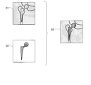
- the image processing apparatus is an image processing apparatus that performs image processing on an original image P0 in which a metal piece obtained by radiographing a subject with a metal piece embedded therein is captured.
- modes for carrying out the present invention will be described.
- the image processing apparatus 1 is configured to output a color tone corrected image P7 obtained by correcting the color tone of the original image P0 when the original image P0 is input.
- the original image P0 is an image obtained by X-ray imaging of a subject in which a metal piece is embedded.
- the original image P0 includes an image of a metal piece in the subject. That is, the metal piece m0 which comprises an artificial joint is shown by the original image P0 of FIG.
- the portion other than the metal piece m0 in the original image P0 is composed of pixels having similar pixel values, and it cannot be said that the visibility is high.
- tone correction is performed on the original image P0.
- the pixel values of the pixels constituting the original image P0 are converted to a color correction image P7 that has undergone a certain adjustment and improved in visibility.
- the image processing apparatus 1 excludes the metal piece m0 that appears in the original image P0, and performs image processing only on a portion other than the metal piece m0. Therefore, the metal piece m0 reflected in the original image P0 is in a state of being copied from the original image P0 to the tone correction image P7 without image processing.
- the portions other than the metal piece m7 of the color tone correction image P7 have improved visibility from the viewpoint of the diagnostician. That is, the metal piece m0 reflected in the original image P0 is not a living tissue in the subject, but the diagnostician is interested in a portion other than the metal piece m0 in the original image P0.
- This portion is composed of pixels having similar pixel values on the original image P0, and the structure is not clear and the visibility is low. However, in this portion, the contrast of the pixel value is adjusted in the color tone correction image P7, and the visibility is improved.
- the diagnostician can accurately diagnose portions other than the metal piece m0 whose visibility has been improved by using the color tone correction image P7 for diagnosis.
- the image processing apparatus 1 is configured to perform the color tone correction by excluding the metal piece m0 from the original image P0, so that it is necessary to surely improve the visibility of portions other than the metal piece m0. Because there is.
- the image processing apparatus 1 includes the metal piece m0 and corrects the color tone of the original image P0, the metal value on the original image P0 is affected by the pixel value of the metal piece m0 that appears extremely whitish in the original image P0.
- the part other than the piece m0 becomes blackish as a whole, and the visibility of the part other than the metal piece m0 is not improved so much. Therefore, the image processing apparatus 1 according to the first embodiment operates so as to recognize the shape of the metal piece m0 reflected in the original image P0 before the color tone correction and to perform the color tone correction on a portion other than the metal piece m0.
- the image processing apparatus 1 includes units 11, 12, 12a, 13, 14, 15, and 16 for the purpose of extracting the metal piece m0 from the original image P0.
- the median filter processing unit 11 performs a median filter on the original image P0 to generate a filtered image P1.
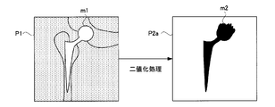
- the binarization unit 12a performs binarization processing on the filtered image P1 to generate a binarized image P2a.
- the inversion unit 12b inverts the binarized image P2a to generate an inverted binarized image P2b.
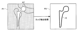
- the edge extraction unit 13 performs edge extraction processing on the filtered image P1 to generate an edge extracted image P3.
- the image synthesizing unit 14 superimposes the binarized image P2a and the edge extracted image P3 to generate a synthesized image P4a, and superimposes the inverted binarized image P2b and the edge extracted image P3 to relate to the inversion.
- a composite image P4b is generated.
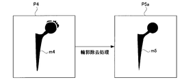
- the contour deletion unit 15 generates a contour deletion metal map P5a by performing contour deletion processing on the composite image P4a, and performs contour deletion processing on the composite image P4b related to inversion to perform contour deletion nonmetal map.
- P5b is generated.
- the graph cut processing unit 16 generates an extracted image P6 in which the metal piece m0 is extracted from the original image P0 based on the original image P0, the contour deleted metal map P5a, and the contour deleted non-metal map P5b.
- the median filter processing unit 11 corresponds to the median filter processing unit of the present invention
- the binarization unit 12a corresponds to the binarization unit of the present invention
- the inversion unit 12b includes the inversion unit of the present invention. It corresponds to.
- the edge extraction unit 13 corresponds to the edge extraction processing unit of the present invention
- the image synthesis unit 14 corresponds to the image synthesis unit of the present invention.
- the contour deletion unit 15 corresponds to the contour deletion processing unit of the present invention
- the graph cut processing unit 16 corresponds to the graph cut processing unit of the present invention.
- the image processing apparatus 1 recognizes the position, size, and range of the metal piece m0 on the original image P0 based on the extracted image P6, and performs color tone correction on portions other than the metal piece m0 on the original image P0.
- a color correction image P7 is generated.
- the color correction unit 17 performs this color correction.
- specific operations of these units will be described in order.
- the color tone correction unit 17 corresponds to a color tone correction processing unit of the present invention.
- FIG. 2 illustrates the filtering process that the median filter processing unit 11 performs on the original image P0.
- the original image P0 includes noise on fine grains. Such noise is either extremely dark or extremely bright in the original image P0. Such noise hinders extraction of the metal piece m0 to be performed. Therefore, according to the present invention, the median filter processing unit 11 erases the on-grain noise on the original image P0 prior to the extraction operation. Specifically, the noise is eliminated by the median filter processing unit 11 applying a median filter to the original image P0. The image generated by this process will be called a filtered image P1.
- Median filter processing is a kind of matrix filter used in image processing, and is image processing in which pixel values of pixels constituting an image are replaced with pixels around the pixels. Thereby, the pixel value of the pixel is replaced with an intermediate pixel value among the pixel values of the surrounding pixels. With this operation, the noise on the grains that appeared in the original image P0 is removed. In this way, the median filter processing unit 11 performs a median filter on the original image P0.
- the filtered image P1 is sent to the binarization unit 12a.
- the binarization unit 12a provisionally extracts the metal piece m0 on the original image P0 based on a preset threshold value. That is, the binarization unit 12a compares the pixel value of the pixel constituting the original image P0 with the threshold value, so that the pixel belongs to a portion where the radiation exposure is high or low in the original image P0. Determine whether.
- the binarization unit 12a performs this determination for all the pixels on the original image P0, and outputs the determination result as a binarized image P2a as shown in FIG. In the case of FIG. 3, the black portion is a portion determined to have little exposure to radiation.
- the white portion in FIG. 3 is a portion determined to have a lot of radiation exposure.
- the pixel value of the black portion is 1, and the pixel value of the white portion is 0.
- the binarization unit 12a binarizes the original image P0, thereby generating a binarized image P2a in which a rough image of the metal piece m0 reflected in the original image P0 is captured.
- the reversing unit 12b inverts the binarized image P2a to generate an inverted binarized image P2b.
- the inverted binary image P2b will be described later.
- the reversing unit 12b performs reversal processing on the binarized image P2a, thereby generating a reversal binarized image P2b in which a rough image of a portion other than the metal piece m0 in the original image P0 is captured.
- the binarized image P2a obtained in this way roughly represents the position of the metal piece m0 in the original image P0.
- Metals have a characteristic of extremely absorbing X-rays compared to bones constituting the subject. Accordingly, the metal piece m0 is extremely less exposed to X-rays in the original image P0.
- the original image P0 is a photograph obtained by exposing X-rays. Therefore, if the pixels of the original image P0 are divided into two groups according to the size of the pixel value, the group of pixels grouped with those with less radiation exposure is a metal piece m0 with extremely less X-ray exposure. Should be configured.
- FIG. 4 explains the reason.
- a part of the filtered image P1 is enlarged, it can be seen that a gradation appears between the metal piece m1 on the filtered image P1 and the other part. That is, there is an intermediate band C between the metal piece m1 and the other part that is difficult to distinguish at first glance as to which part belongs to each other.
- the intermediate band C many pixels having a pixel value similar to the pixel value indicated by the above-described threshold value can be seen. Therefore, when the binarization process is performed on the intermediate band C, misjudgment occurs in the determination as to whether or not it belongs to the metal piece m1.
- the shape of the metal piece m2 on the binarized image P2a is different from that of the metal piece m1 on the filtered image P1. This is because the shape of the metal piece m2 on the binarized image P2a is disturbed due to the erroneous determination that occurs on the intermediate band C as described above.
- FIG. 5 is a partially enlarged view of the binarized image P2a representing the state.
- the metal piece m2 on the binarized image P2a protrudes into the intermediate band C that covers a portion that can be recognized as a metal piece in the broken line.
- the shape of the metal piece m2 on the binarized image P2a is inaccurate at the boundary of the shape.
- the intermediate zone C where it is difficult to determine whether it belongs to such a metal piece, in order to accurately identify the metal piece, it is necessary to use a binarization process or another method.
- the boundary between the metal piece and the portion other than the metal piece is determined with uncertainty based on the original judgment.
- a portion corresponding to the intermediate band C on the binarized image P2a is excluded from the metal piece m2, and then the excluded portion is analyzed in detail as to whether it is a metal piece by a more reliable method. There is a need to. In order to perform such an operation, it is first necessary to know the shape of the intermediate band C.
- the edge extraction unit 13 is provided for the purpose of extracting the above-described intermediate band C from the filtered image P1.
- FIG. 6 illustrates what kind of edge extraction processing the edge extraction image P3 performs on the filtered image P1.
- generated by edge extraction processing is not a binary image, in FIG. 6, it demonstrates as a binary image for convenience of explanation.
- This edge extraction process is executed by applying a Laplacian filter process to the image.
- Laplacian filter processing is a type of image processing that can enhance the boundary between an image reflected in an image and the background by performing differential processing on the image.
- FIG. 7 shows an operation in which the edge extraction unit 13 performs an edge extraction process on the filtered image P1 to generate an edge extracted image P3.
- the edge extraction image P3 is an image in which the boundary between the metal piece m1 and the background (portion other than the metal piece m1) of the filtered image P1 is extracted.
- FIG. 8 explains the reason why such a phenomenon occurs.
- the left side of FIG. 8 is an enlarged view of a part of the filtered image P1.
- the right side of FIG. 8 illustrates an edge E obtained by performing edge extraction processing on the filtered image P1 shown on the left side of FIG.
- the right side of FIG. 8 shows two of the edge E and the filtered image P1 that is the basis of the edge extraction process overlapped.
- the edge E is located near the center of the intermediate band C due to the nature of image processing.
- FIG. 9 explains the reason why the edge E is located near the center of the intermediate zone C.
- the graph of FIG. 9 is a graph in which the pixel value and the position on the filtered image P1 are related.
- the left side of the graph corresponds to a portion where a portion other than the metal piece m1 on the filtered image P1 is reflected, and the right side of the graph corresponds to a portion where the metal piece m1 on the filtered image P1 is reflected.
- the middle zone C is in the middle of each part.
- Edge extraction by the edge extraction unit 13 is performed by spatially differentiating pixels.
- the edge extraction unit 13 performs edge extraction processing on the original image P0, so that the position in the vicinity of the center of the intermediate band C between the portion with high radiation exposure and the portion with low exposure in the original image P0.
- the edge extraction image P3 from which the edge E indicating is extracted is generated.
- a binarized image P2a and an edge extracted image P3 are sent to the image composition unit.
- the image composition unit 14 superimposes the binarized image P2a and the edge extracted image P3 to replace the pixel value of the binarized image P2a on which the edge E is overlapped with the edge extracted image P3 with 0.
- FIG. 10 shows the operation at this time.
- a metal piece m4 that appears to be similar to the metal piece m2 on the binarized image P2a is reflected, but when viewed closely, they are different from each other.
- the metal piece m2 appears on the image as a single lump, whereas the metal piece m4 has a notch derived from the edge E.
- the metal piece m4 is divided into a plurality of parts.
- the image composition unit 14 generates the composite image P4a in which the image on the binary image P2a is divided near the center of the intermediate band by superimposing the binary image P2a and the edge extraction image P3. To do.
- FIG. 11 illustrates a part of each image in an enlarged manner as to which part of the metal piece m2 on the binarized image P2a is cut by the image composition processing. Since the metal piece m2 protrudes from the intermediate band C and the edge E is located at the center of the intermediate band C, the metal piece m4 in the composite image P4a clearly belongs to the metal piece (in other words, No cut is made in the portion that does not belong to the intermediate band C). Rather, the metal piece m4 has a notch in the protruding portion indicated by A in FIG. In the metal piece m2, the protruding portion is a large protruding portion that exists over almost the entire area of the intermediate band C beyond the center of the intermediate band C.
- the pixel value of the pixel located at the center of the intermediate band C on the binarized image P2a is converted to 0. Therefore, this protruding portion is caused by the channel generated by the pixel value conversion. Isolated from metal pieces on the image. Therefore, in the metal piece m4 in FIG. 11, the part A is represented like an isolated island. In this way, the pixel at the position near the center of the intermediate band C in the binarized image P2a is excluded from the metal piece by the image synthesis process. However, in this image processing, as shown in the lower side of FIG. 11, not all protruding portions (portions outside the broken line) are excluded from the metal pieces.
- the contour deleting unit 15 is provided for the purpose of setting the pixel value of the protruding portion still remaining in the composite image P4a to zero. Thereby, the entire region of the protruding portion that protrudes into the intermediate band C among the metal piece m2 on the binarized image P2a is excluded from the metal piece m2. In this way, the contour deletion unit 15 generates the contour deletion metal map P5a in which the intermediate band C is deleted from the image on the composite image P4a by deleting the contour of the image on the composite image P4a.
- the contour deleting unit 15 cuts the metal piece m4 on the composite image P4a by a predetermined width.
- the cutting performed by the contour deleting unit 15 is an operation for setting a pixel value of pixels constituting the contour to 0 for a block of pixels appearing on the image, and is different from general graphic reduction. It is a concept.
- FIG. 12 shows a contour deletion process performed by the contour deletion unit 15. For example, it is assumed that there is an image in which an annular image is reflected as shown on the left side of FIG. When the contour deletion process is performed on this image, as shown on the right side of FIG. 11, the contour portion of the annular image is cut and the ring becomes thin. The dotted line on the right side of FIG. 11 represents the contour of the image before cutting.
- FIG. 13 specifically illustrates the contour deletion processing performed by the contour deletion unit 15 on the composite image P4a.
- the contour deleting unit 15 continues the operation of scraping the block of pixels constituting the metal piece m4 from the contour until there are no pixels belonging to the intermediate band C (pixels belonging to the protruding portion). Therefore, the width of the intermediate band C must be acquired in advance prior to this image processing.
- the width of the intermediate band C can be easily obtained by observing the original image P0.
- the acquired width can be used for contour deletion processing for other X-ray images. This is because the width of the intermediate band C does not vary so much between X-ray images.
- the contour deletion process is an image process that cuts the contour of the metal piece m4. Therefore, if the position is in the vicinity of the center of the intermediate band C indicated by the point p in FIG. 13, the contour is cut from two directions. That is, one is the cutting in the direction from the point p that cuts the metal piece m4 main body downward. The other is the cutting in the direction from the point p that cuts the isolated island A upward. The solitary island A disappears by this upper cutting.
- the width of the solitary island A across the intermediate zone C is less than half the width of the intermediate zone C. This is because the protrusion A appearing in the binarized image P2a is a pixel that is distributed as a pixel with less exposure by the binarization process, and is within the width of the intermediate band C in the first place. Therefore, the outline deletion process is performed by cutting the metal piece m4 from the vicinity of the center of the intermediate band C by a thickness that is half the width of the intermediate band C. If the strength of this contour deletion processing is this level, the isolated island A that is less than half the thickness of the intermediate zone C is surely erased.
- FIG. 14 illustrates a case where the contour deletion process is performed directly on the binarized image P2a.
- the binarized image P2a has a protrusion A.
- the protrusion A is not an isolated island as in the composite image P4a, but rather is a peninsula protruding from the metal piece main body.
- the contour deletion process is performed on such a binarized image P2a, as shown in the lower side of FIG. 14, a part of the protruding portion remains without being cut off.
- the contour deletion process is an image process in which a layer having a certain thickness is removed from an image on the image.
- the protrusion A has a peninsular shape, the protruding portion of this portion is too thick as indicated by an arrow, and the entire contour cannot be deleted by the contour deletion processing. Such a situation is undesirable from the viewpoint of the accuracy of image processing.
- the protruding portion from the center of the intermediate band C exposed by the overlap of the edge E can be cut. That is, in the composite image P4a, since the thickness of the protruding portion around the metal piece is uniform, the protruding portion can be deleted without excess or shortage by stripping the uniform thickness from the image.
- the contour deleted metal map P5a is generated in which the protruding portion remaining in the composite image P4a is removed.
- This map represents the distribution of metal pieces in the original image P0, and the portion recognized as a metal piece does not include any portion other than the metal piece. However, this map only maps a portion that can be reliably identified as a metal piece in the original image P0.
- the pixel located in the intermediate band C is handled as not constituting a metal piece.
- FIG. 15 shows a state in which a contour deletion metal map P5a is generated from the composite image P4a by the contour deletion processing as described above.
- the metal piece m5 on the map is slightly smaller than the metal m4 due to the cutting operation.
- the small isolated island created by dividing the metal piece m2 at the edge E when the composite image P4a is generated is erased in the contour deleted metal map P5a.
- FIG. 16 is a diagram for explaining a part of the generated contour deleted metal map P5a in an enlarged manner. As shown in FIG. 16, the metal piece m5 does not include the intermediate band C.
- the image composition unit 14 and the contour deletion unit 15 perform the same operation as that performed on the binarized image P2a for the inverted binarized image P2b, and are located in the intermediate band C in the inverted binarized image P2b.
- a contour deleted non-metal map P5b is generated by excluding pixels from portions other than metal pieces.
- the image composition unit 14 superimposes the inverted binarized image P2b and the edge extracted image P3, so that the image on the inverted binarized image P2b is divided in the vicinity of the center of the intermediate band.
- P4b is generated.
- the contour deleting unit 15 generates a contour deleted non-metallic map P5b in which the intermediate band C is deleted from the image on the image by deleting the contour of the image on the composite image P4b related to inversion.
- This map represents the distribution of the part other than the metal piece m0 in the original image P0, and the metal piece m0 is not mixed in the part recognized as other than the metal piece m0.
- this map is only a map of a portion that can be reliably identified as a portion other than the metal piece m0 in the original image P0.
- the pixel located in the intermediate band C in the contour deleted non-metal map P5b is handled as not constituting any part other than the metal piece m0.
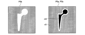
- the contour deleted non-metallic map P5b generated in this way is shown on the left side of FIG.
- FIG. 17 The right side of FIG. 17 is a diagram when the contour deleted metal map P5a and the contour deleted non-metal map P5b are overlaid. From this superposition diagram, it can be noticed that an intermediate band that does not belong to either of the metal piece m5 and the non-metal region n5 appears.
- the band that appears white in this figure is the intermediate band C that is difficult to determine whether it belongs to a metal piece.
- the determination of the pixels constituting the intermediate band C is performed by the following image processing.
- the graph cut processing unit 16 receives the filtered image P1, the contour deleted metal map P5a, and the contour deleted nonmetal map P5b.
- the graph cut processing unit 16 analyzes pixels belonging to the intermediate band C by graph cut processing based on these images. Pixels that have been subjected to the graph cut processing are accurately assigned to belong to a metal piece or a non-metal region.
- the graph cut processing unit 16 recognizes that the image on the contour-removed metal map P5a forms part of the metal piece m1 reflected in the filtered image P1, and applies the graph cutting process to the filtered image P1. Then, an extracted image P6 is generated by extracting the image of the metal piece m1 reflected in the filtered image P1.
- the graph cut processing unit 16 recognizes that the image on the contour-removed non-metallic map P5b forms part of the portion other than the metal piece m1 reflected in the filtered image P1, and creates the filtered image P1. A graph cut process is performed.
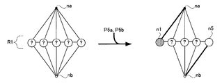
- FIG. 18 explains the concept of node n used in the graph cut method. Assume that there is an image composed of pixels a arranged two-dimensionally on the left side of FIG. In the graph cut method, these pixels a are interpreted as nodes n connected to each other. Each of the nodes n corresponds to each of the pixels a. Therefore, the nodes n are two-dimensionally arranged. Each of the two-dimensionally arranged nodes n is connected to a node n adjacent to each other. Nodes n connected to each other are deeply related, and form one lump. From this, by releasing the connection between the nodes n one after another, the lump that is one in the entire image is decomposed into two lumps. One of the blocks thus decomposed is composed of only a node n corresponding to a pixel belonging to a metal piece. The other block is composed of only nodes n corresponding to pixels belonging to the non-metal region.
- FIG. 19 shows the first stage of the graph cut method.
- the node na is a virtual node that represents a pixel belonging to a metal piece. This node na is connected to all the nodes n.
- the node nb is a virtual node representing a pixel belonging to the non-metal region. This node nb is also connected to all the nodes n.
- the graph cut processing unit 16 distributes the node n with reference to the contour deleted metal map P5a and the contour deleted non-metal map P5b.
- the node n corresponding to the pixel belonging to the metal piece in the contour deleted metal map P5a is strongly tied to the node na and is disconnected from the node nb.
- the node n corresponding to the pixel that belongs to the nonmetal region in the contour deleted nonmetal map P5b is strongly tied to the node nb, and the connection with the node na is released. This operation is not a burden on the arithmetic device that implements the graph cut method.
- a node n2 shown in FIG. 20 is a pixel belonging to a so-called intermediate zone C that has not received any authorization in any of the maps P5a and P5b.
- the graph cut processing unit 16 pays attention to the connection line connected to the node n2. These connection lines are assigned evaluation values called costs.
- the graph cut processing unit 16 cuts the connection line by comparing the costs. This cost is determined by the pixel value of the pixel corresponding to the node n. That is, when the pixel values of adjacent pixels are similar, the cost of the connection line between the nodes n corresponding to the adjacent pixels is set low.
- the cost of the connection line between the node n and the node na corresponding to this pixel is set low.
- the cost of the connection line between the node n and the node nb corresponding to this pixel is set low.
- the low cost represents the depth of relevance between nodes.
- the graph cut processing unit 16 repeats cutting the connection line while maintaining the connection line with low cost. For example, in the example of FIG. 20, the node n2 has been determined that the connection between the node n and the node nb on the right is released and the pixel a corresponding to the node n2 belongs to the metal piece. Such processing for connection lines places a heavy burden on the arithmetic unit that implements the graph cut method.
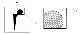
- FIG. 21 shows the node n that has been classified as an image by the graph cut method.
- the diagram generated in this way will be referred to as an extracted image P6 from which a metal piece reflected in the original image P0 is extracted.
- this extracted image P6 is enlarged, the shape of the smooth metal piece is faithfully represented.
- the extracted image P6 is an image in which the metal piece is correctly extracted for the intermediate band C as well.
- the extracted image P6 is sent to the color tone correction unit 17.
- the color correction unit 17 performs color correction on the original image P0 with reference to the extracted image P6 to generate a color correction image P7.
- the color tone correction unit 17 performs dynamic range processing and contrast adjustment processing on the portion of the original image P0 excluding the metal piece.
- FIG. 22 shows such a state. As shown in FIG. 22, the color tone correction unit 17 operates only for portions other than the metal piece indicated by the oblique lines in the original image P0. The metal piece that appears in the original image P0 at this time does not constitute the original image P0. Accordingly, the color tone correction unit 17 does not read the pixel value or convert the pixel value for the metal piece.
- the color tone correction unit 17 converts the pixel value of the pixel located in the shaded portion shown on the left side of FIG. 22 into a highly visible one.
- the pixel values of the pixels located in the shaded area are similar, and the difference between the pixels is not clear.
- the difference in pixel values is emphasized by the color correction. Therefore, the color tone correction image P7 generated by the color tone correction has high visibility.
- the color tone correction image P7 is not processed for the metal piece. This is convenient for improving the visibility of the color tone correction image P7.
- the metal piece is not a part of interest to the diagnostician, and it is not affected by extreme pixel values derived from the metal piece during color tone correction, and the visibility of the part other than the metal piece does not deteriorate. It is.
- the color tone correction unit 17 refers to the extracted image P6 and performs color tone correction processing on a portion other than the metal piece in the original image P0.
- the image processing apparatus of the present invention it is possible to perform color correction that achieves both reliability and high speed. That is, the image processing apparatus according to the present invention performs graph cut processing on an intermediate band between a portion where the radiation exposure is high and a portion where the exposure is low in the original image P0, thereby determining whether this portion belongs to the metal piece. Judgment is made. Thereby, the outline of the metal piece reflected in the original image P0 is accurately extracted.
- This graph cut processing has a drawback that it is highly reliable but has a large calculation load. Therefore, according to the present invention, a contrivance is made to reduce this calculation load as much as possible.
- the image processing apparatus binarizes the original image P0 to generate a binarized image P2a that includes a rough image of a metal piece that is reflected in the original image P0.
- an edge extraction unit 13 that extracts a position near the center of the intermediate band C in the original image P0, and an image composition that generates a composite image P4a in which the image on the binarized image P2a is divided near the center of the intermediate band C.
- Unit 14 and a contour deleting unit 15 that deletes the intermediate band by deleting the contour of the image on the composite image P4a.
- the image on the binarized image P2a is divided in the vicinity of the center of the intermediate band, and then the image is trimmed from the vicinity of the center of the intermediate band in order to make the outline deletion process light. It has a configuration. By doing so, it is possible to minimize the range where the image is sharpened. As a result, the number of pixels that have to be subjected to the graph cut processing in the original image P0 is reduced, and the image processing is speeded up.
- the median filter is applied to the original image P0 referred to by the binarization unit 12a and the edge extraction unit and the graph cut processing unit 16 as in the above-described configuration, the noise component seen in the original image P0 Are removed by the filtering process, so that the metal piece reflected in the original image P0 can be extracted more accurately.
- the edge extraction unit 13 applies a Laplacian filter to the original image P0, so that the vicinity of the center of the intermediate band can be reliably extracted.
- the Laplacian filter is a spatial differential filter.
- the above-described configuration also shows the operation of the original image P0 other than the metal piece. That is, the image processing apparatus according to the present invention generates an inverted binarized image P2b in which a rough image of a portion other than a metal piece reflected in the original image P0 is captured, and based on this, the inverted binarized image P2b is generated.
- An image on the composite image P4b related to the inversion is generated by generating a composite image P4b related to the inversion in which the upper image is divided in the vicinity of the center of the intermediate band and then deleting the outline of the image on the composite image P4b related to the inversion. Configured to delete the intermediate band from
- the internal shape of the part other than the metal piece reflected in the original image P0 is reliably extracted. Since this internal shape surely constitutes a portion other than the metal piece without performing the graph cut processing, the graph cut processing of this portion can be omitted.
- the image on the binarized image P2a is divided in the vicinity of the center of the intermediate band, and then the image is trimmed from the vicinity of the center of the intermediate band in order to make the outline deletion process light. It has a configuration. By doing so, it is possible to minimize the range where the image is sharpened. As a result, the number of pixels that have to be subjected to the graph cut processing in the original image P0 is reduced, and the image processing is speeded up.
- the configuration of the second embodiment is devised so as to make the tomographic image clear by the image processing apparatus of the present invention.
- the tomographic image here is an image in which an image obtained when the subject M is cut at a certain cutting plane is reflected, and is generated using a radiation imaging apparatus.
- the image processing apparatus 22 according to the second embodiment includes the units 11, 12a, 12b, 13, 14, 15, 16 in the first embodiment. Note that, unlike the first embodiment, the image processing apparatus 22 according to the second embodiment does not include the color tone correction unit 17.
- Example An example of a radiation tomography apparatus capable of generating a tomographic image according to Example 2 will be described with reference to the drawings.
- the X-ray in an Example is corresponded to the radiation of the structure of this invention.
- FPD is an abbreviation for flat panel X-ray detector (flat panel detector).
- the X-ray imaging apparatus 50 of the present invention is for follow-up after an artificial joint replacement operation.
- FIG. 23 is a functional block diagram illustrating the configuration of the X-ray imaging apparatus 50 according to the first embodiment.
- the X-ray imaging apparatus 50 according to the first embodiment includes a top plate 2 on which a subject M, which is a target of X-ray tomography, and an upper portion of the top plate 2 (1 of the top plate 2).
- An X-ray tube 3 that irradiates the subject M with a cone-shaped X-ray beam toward the subject M, and a lower portion of the top 2 (the other side of the top).
- the X-ray tube 3 and the FPD 4 are respectively connected to the FPD 4 that detects X-rays transmitted through the subject M, and the center axis of the cone-shaped X-ray beam and the center point of the FPD 4 are always coincident with each other.
- a synchronous movement mechanism 7 that moves synchronously in opposite directions across the region of interest
- a synchronous movement control unit 8 that controls the synchronous movement mechanism 7, and scattered X-rays provided so as to cover the X-ray detection surface that detects the X-rays of the FPD 4
- an X-ray grid 5 that absorbs.
- the top plate 2 is disposed at a position sandwiched between the X-ray tube 3 and the FPD 4.
- the synchronous movement mechanism 7 includes an X-ray tube movement mechanism 7a that moves the X-ray tube 3 in the body axis direction A with respect to the subject M, and an FPD movement mechanism that moves the FPD 4 in the body axis direction A with respect to the subject M. 7b.
- the synchronous movement control unit 8 includes an X-ray tube movement control unit 8a that controls the X-ray tube movement mechanism 7a and an FPD movement control unit 8b that controls the FPD movement mechanism 7b.
- the synchronous movement control unit 8 moves the X-ray tube 3 and the FPD 4 in opposite directions when the original image P0 is continuously shot.
- the X-ray tube 3 is configured to repeatedly irradiate the subject M with a cone-shaped and pulsed X-ray beam in accordance with the control of the X-ray tube control unit 6.
- the X-ray tube 3 is provided with a collimator that collimates the X-ray beam into a cone shape that is a pyramid.
- the X-ray tube 3 and the FPD 4 generate imaging systems 3 and 4 that capture an X-ray projection image.
- the X-ray tube control unit 6 controls the X-ray tube 3 according to set values indicating tube current, tube voltage, pulse width, etc. when the X-ray tube 3 is controlled.
- the synchronous movement mechanism 7 is configured to move the X-ray tube 3 and the FPD 4 in synchronization with the subject M.
- the synchronous movement mechanism 7 linearly moves the X-ray tube 3 along a linear trajectory (longitudinal direction of the top 2) parallel to the body axis direction A of the subject M according to the control of the synchronous movement control unit 8.
- the moving direction of the X-ray tube 3 and the FPD 4 coincides with the longitudinal direction of the top 2.
- the cone-shaped X-ray beam irradiated by the X-ray tube 3 is always irradiated toward the region of interest of the subject M.
- the X-ray irradiation angle is determined by the X-ray tube 3.
- the initial angle is changed from ⁇ 20 ° to the final angle of 20 °.
- Such an X-ray irradiation angle change is performed by the X-ray tube tilting mechanism 9.
- the X-ray tube tilt control unit 10 is provided for the purpose of controlling the X-ray tube tilt mechanism 9.
- the X-ray imaging apparatus 50 further includes a main control unit 25 that controls the control units 6, 8, 10, 11, and 12 in an integrated manner, and a display unit 27 that displays a tomographic image. ing.
- the main control unit 25 is constituted by a CPU, and realizes the control units 6, 8, 10 and the later-described units 21, 22, 23 by executing various programs.
- the storage unit 28 stores all data related to control of the X-ray imaging apparatus 50 such as parameters related to control of the X-ray tube 3.
- the console 26 allows the operator to input each operation on the X-ray imaging apparatus 50.
- the synchronous movement mechanism 7 synchronizes with the linear movement of the X-ray tube 3 described above, and causes the FPD 4 provided at the lower part of the top 2 to move in the body axis direction A (the longitudinal direction of the top 2) of the subject M. Move straight ahead.
- the moving direction is opposite to the moving direction of the X-ray tube 3.
- a cone-shaped X-ray beam whose focal position and irradiation direction change as the X-ray tube 3 moves is always received by the entire surface of the X-ray detection surface of the FPD 4. Yes.
- the FPD 4 acquires, for example, 74 projected images while moving in synchronization with the X-ray tube 3 in the opposite directions.
- the imaging systems 3 and 4 are opposed to the position indicated by the alternate long and short dash line illustrated in FIG. 23 via the position indicated by the broken line, with the position of the solid line as the initial position. That is, a plurality of X-ray projection images are taken while changing the positions of the X-ray tube 3 and the FPD 4.
- the central axis of the cone-shaped X-ray beam during imaging always coincides with the center point of the FPD 4.
- the center of the FPD 4 moves straight, but this movement is in the direction opposite to the movement of the X-ray tube 3. That is, the X-ray tube 3 and the FPD 4 are moved in the body axis direction A synchronously and in directions opposite to each other.
- FIG. 24 is a diagram for explaining a tomographic image acquisition method of the X-ray imaging apparatus according to Embodiment 1.
- a virtual plane reference cut surface MA
- points P and Q positioned on the reference cut surface MA are always set.
- the FPD 4 is synchronized with the opposite direction of the X-ray tube 3 in accordance with the irradiation direction of the cone-shaped X-ray beam B by the X-ray tube 3 so as to be projected onto the fixed points p and q of the X-ray detection surface of the FPD 4.
- a series of original images P1 and P2 are generated by the image generation unit 21 while being moved.
- the projected image of the subject M is reflected while changing the position.
- images for example, fixed points p and q
- the point I not located on the reference cut surface MA is reflected as a point i in a series of subject M images while changing the projection position on the FPD 4.
- a point i is blurred without forming an image when the tomographic image generation unit 23 superimposes the X-ray projection images.
- an X-ray tomographic image in which only an image positioned on the reference cut surface MA of the subject M is reflected is obtained.
- the tomographic image generation unit 23 corresponds to the tomographic image generation means of the present invention.
- the tomographic image generation unit 23 can obtain a similar tomographic image even at an arbitrary cut surface horizontal to the reference cut surface MA.
- the projection position of the point i moves in the FPD 4, but this moving speed increases as the separation distance between the point I before projection and the reference cut surface MA increases.
- reconstruction is performed while shifting the acquired series of subject M images in the body axis direction A at a predetermined pitch, and a tomographic image at a cutting plane parallel to the reference cutting plane MA is obtained. It is done.
- Such a series of tomographic image reconstruction is performed by the tomographic image generation unit 23.
- the image processing apparatus 22 has a configuration in which the units 11, 12a, 12b, 13, 14, 15, and 16 described in the first embodiment are collectively expressed.
- the image processing device 22 binarizes each of the 74 original images P0 to generate 74 extracted images P6 (see FIG. 25).
- the extracted image P6 is a binarized image in which metal pieces that are reflected in the original image P0 are extracted.
- a tomographic image is generated by performing image reconstruction processing on 74 original images P0 by the tomographic image generating unit 23. Therefore, if only the tomographic image is generated, it is not necessary to generate the extracted image P6 by the image processing device 22. However, if the original image P0 is simply reconstructed, only a tomographic image in which a false image appears can be obtained. This is because a metal piece is reflected in each of the original images P0. Since this metal piece has an extreme pixel value, it cannot be sufficiently blurred by overlapping the original image P0. Therefore, an afterimage of the metal piece that cannot be canceled out by superimposing the images appears around the metal piece in the tomographic image. This afterimage is a false image that appears in the tomographic image.
- the X-ray tomography apparatus according to the second embodiment is devised so that such a false image does not occur in the tomographic image. That is, the X-ray tomography apparatus according to the second embodiment is configured such that a false image does not appear in the tomographic image by devising the superposition of metal pieces by the function of the image processing apparatus 22. That is, the tomographic image in the second embodiment is not generated by superimposing the original image P0 as it is. That is, as shown in FIG. 25, the tomographic image is generated by the tomographic image generation unit 23 while referring to the extracted image P6 in which the metal piece is extracted from each of the original images P0. The extracted image P6 is made when the image processing device 22 performs metal piece extraction processing on each of the 74 original images P0. Therefore, 74 extracted images P6 are generated.
- the tomographic image generation unit 23 generates a tomographic image while referring to the extracted image P6 generated by the image processing device 22. This situation will be specifically described.
- the tomographic image generation unit 23 performs image processing for erasing the image of the metal piece reflected in each of the original images P0. That is, as shown in FIG. 26, the tomographic image generation unit 23 refers to the extracted image P6 to grasp the position / size / range of the metal piece reflected in the original image P0. Then, the tomographic image generation unit 23 converts the pixel value of the pixel inside the metal piece into the pixel value of the pixel around the metal piece.
- the pixel value related to the conversion at this time is, for example, an average value of pixel values of pixels around the metal piece.
- a metal piece removal image P8 is generated in which the metal piece reflected in the original image P0 is assimilated around.
- This metal piece removal image P8 is generated for each of the 74 original images P0.
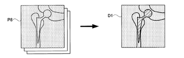
- the tomographic image generation unit 23 refers to the extracted image P6 in which the image of the metal piece is extracted from each of the original images P0 continuously captured while changing the imaging direction with respect to the subject M, and the original image A metal piece removal process is performed to erase the metal piece reflected in P0 from the original image P0 and generate a metal piece removal image P8.
- the tomographic image generation unit 23 performs image reconstruction processing on the 74 pieces of metal piece removed images P8 to generate a tomographic image.
- the image generated at this time is called a metal piece removal tomographic image D1 for distinction. Since the metal piece removal tomographic image D1 is generated by performing image reconstruction processing on an image in which the metal piece is assimilated with the periphery of the metal piece, no false image appears around the metal piece. . However, the portion corresponding to the metal piece indicated by the hatched portion in the metal piece removal tomographic image D1 in FIG. 27 is filled with incorrect pixel values.
- the tomographic image generator 23 operates to bring the pixel value of the metal piece portion in the metal piece removal tomographic image D1 closer to the correct one.
- the tomographic image generation unit 23 performs the metal piece removal tomographic image generation process for generating the metal piece removal tomographic image D1 by performing the image reconstruction process on the plurality of metal piece removal images P8.
- the extracted image P6 is a binarized image and represents the shape of the metal piece on the original image P0, whereas the trimmed image P9 has not only the shape of the metal piece but also the shading inside the metal piece.
- the image is shown.
- the metal piece in the trimmed image P9 appears to be thinner than the metal piece reflected in the original image P0.
- the pixel value of the metal piece of the metal piece removal image P8 (the pixel value of the pixels around the metal piece in the original image P0) is subtracted from the pixel value of the pixel on the metal piece of the original image P0. Because.
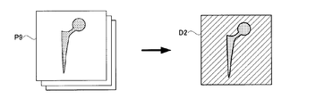
- the tomographic image generation unit 23 performs the metal piece trimming process for generating the trimming image P9 in which the portion corresponding to the metal piece is extracted from each of the original images P0 with reference to the extracted image P6.
- ⁇ Operation of the tomographic image generation unit 23 generation of a metal piece tomographic image>
- the tomographic image generation unit 23 performs image reconstruction processing on 74 trimmed images P9 to generate a tomographic image.
- the image generated at this time is called a metal piece tomographic image D2 for distinction.
- the metal piece tomographic image D2 is a tomographic image having a cut surface in common with the metal piece removal tomographic image D1. Further, since the metal piece tomographic image D2 is generated by performing image reconstruction processing on an image in which only the metal piece is reflected, the tomographic image of the metal piece is captured.
- the tomographic image generation unit 23 performs the metal piece tomographic image generation process for generating the metal piece tomographic image D2 by performing the image reconstruction process on the plurality of trimmed images P9.
- the tomographic image generation unit 23 generates two different types of tomographic images. Finally, the tomographic image generation unit 23 performs a process of adding the tomographic images D1 and D2 as shown in FIG.
- the tomographic image generated in this way is referred to as a synthetic tomographic image D3 for distinction.
- This synthetic tomographic image D3 is excellent in visibility. That is, since the portion other than the metal piece in the composite tomographic image D3 is derived from the metal piece removal tomographic image D1, no false image appears.
- the tomographic image generation unit 23 adds the metal piece removal tomographic image D1 and the metal piece tomographic image D2 to generate a composite tomographic image D3.
- the composite tomographic image D3 is displayed on the display unit 27, and the operation of the apparatus according to the second embodiment is completed.
- the image processing apparatus 1 of the present invention can be used when generating a tomographic image.
- the present invention is not limited to the configuration described above, and can be modified as follows.
- the edge extraction unit 13 described above is not limited to a Laplacian filter, and can be operated by a differential filter for edge extraction.
- the intensity of the cutting is obtained by actually measuring the width of the intermediate band C. Instead of this configuration, all the isolated islands in which the composite image P4a appears are deleted. You may make it perform an outline deletion process.
- the above-described invention is suitable for the medical field.
Landscapes
- Engineering & Computer Science (AREA)
- Health & Medical Sciences (AREA)
- Life Sciences & Earth Sciences (AREA)
- Physics & Mathematics (AREA)
- Medical Informatics (AREA)
- Computer Vision & Pattern Recognition (AREA)
- Radiology & Medical Imaging (AREA)
- General Physics & Mathematics (AREA)
- Theoretical Computer Science (AREA)
- General Health & Medical Sciences (AREA)
- Nuclear Medicine, Radiotherapy & Molecular Imaging (AREA)
- Biomedical Technology (AREA)
- Public Health (AREA)
- Optics & Photonics (AREA)
- High Energy & Nuclear Physics (AREA)
- Heart & Thoracic Surgery (AREA)
- Molecular Biology (AREA)
- Surgery (AREA)
- Animal Behavior & Ethology (AREA)
- Biophysics (AREA)
- Pathology (AREA)
- Veterinary Medicine (AREA)
- Orthopedic Medicine & Surgery (AREA)
- Dentistry (AREA)
- Oral & Maxillofacial Surgery (AREA)
- Quality & Reliability (AREA)
- Image Processing (AREA)
- Image Analysis (AREA)
- Apparatus For Radiation Diagnosis (AREA)
Abstract
Description
すなわち、本発明に係る画像処理装置は、内部に金属片が埋め込まれた被検体を放射線撮影することで得られる金属片を写し込んだ元画像に画像処理を施す画像処理装置であって、元画像を二値化することにより元画像に写り込む金属片の大まかな像を写し込んだ二値化画像を生成する二値化手段と、元画像にエッジ抽出処理を施すことにより、元画像における放射線の露光が多い部分と露光が少ない部分との間にある中間帯の中央付近の位置を示す境界が抽出されたエッジ抽出画像を生成するエッジ抽出処理手段と、二値化画像とエッジ抽出画像とを重ね合わせることにより、二値化画像上の像が中間帯の中央付近で分断された合成画像を生成する画像合成手段と、合成画像上の像の輪郭を削除することにより合成画像上の像から中間帯が削除された輪郭削除金属マップを生成する輪郭削除処理手段と、輪郭削除金属マップ上の像が元画像に写り込んだ金属片の一部をなすものと認識して元画像に対しグラフカット処理を施すことにより、元画像に写り込む金属片の像が抽出された抽出画像を生成するグラフカット処理手段とを備えることを特徴とするものである。
これら各手段により、元画像に写り込む金属片以外の部分の内部形状が確実に抽出される。すなわちこれら手段により、金属境界において金属であると誤検出された金属以外の領域の指定を解除することができる。
図2は、メディアンフィルタ処理部11が元画像P0に対して行うフィルタ処理について説明している。元画像P0には、図2の左側に示すように、細かな粒上のノイズを含んでいる。この様なノイズは、元画像P0において極端に暗いか、または極端に明るいかのどちらかとなっている。この様なノイズは、これから行おうとする金属片m0の抽出の妨げとなる。そこで、メディアンフィルタ処理部11は、本発明によれば、抽出動作に先立ち元画像P0上の粒上ノイズを消去しておく。このノイズの消去は、具体的にはメディアンフィルタ処理部11が元画像P0にメディアンフィルタを施すことによりなされる。この処理により生成された画像をフィルタ処理画像P1と呼ぶことにする。
フィルタ処理画像P1は、二値化部12aに送出される。二値化部12aは、予め設定された閾値に基づいて元画像P0上の金属片m0を暫定的に抽出する。すなわち、二値化部12aは、元画像P0を構成する画素の画素値と閾値とを比較することで、当該画素が元画像P0において放射線の露光が多い部分に属するか、それとも少ない部分に属するかを判定する。二値化部12aは、この判定を元画像P0上の全ての画素について行い、判定結果を図3に示すように二値化画像P2aとして出力する。図3の場合、黒い部分が放射線の露光が少ないと判定された部分である。また、図3の白い部分は放射線の露光が多いと判定された部分である。二値化画像P2aにおける黒い部分の画素の画素値は1であり、白い部分の画素値は0である。このように、二値化部12aは、元画像P0を二値化することにより元画像P0に写り込む金属片m0の大まかな像を写し込んだ二値化画像P2aを生成する。
エッジ抽出部13は、上述の中間帯Cをフィルタ処理画像P1から抽出する目的で設けられている。図6は、このエッジ抽出画像P3がフィルタ処理画像P1に行うエッジ抽出処理がいかなるものか説明している。まず、図6左側にあるように暗い画像の中に円形の明るい像が写り込んだ画像があるとする。この様な画像にエッジ抽出を行うと、図6右側に示すように円環状の部分とそれ以外の部分とで色分けがされた画像が取得できる。なお、エッジ抽出処理により生成される画像は二値画像ということではないが、図6においては説明の便宜上、二値画像として説明している。このエッジ抽出処理は、画像にラプラシアンフィルタ処理を施すことにより実行される。ラプラシアンフィルタ処理は、画像に微分処理を施すことにより画像に写り込む像と背景との境界を強調することができる画像処理の一種である。
画像合成部14には、二値化画像P2aとエッジ抽出画像P3とが送られてくる。画像合成部14は、二値化画像P2aとエッジ抽出画像P3を重ね合わせることにより、エッジ抽出画像P3でエッジEが重ねられる二値化画像P2aの画素値を0に置き換える。図10はこのときの動作を表している。この様にして得られた合成画像P4aには、二値化画像P2a上の金属片m2と一見同じような金属片m4が写り込んでいるが、よく見るとそれらは互いに異なっている。すなわち、金属片m2は一つのまとまった塊として画像上に現れていたのに対し、金属片m4は、エッジEに由来する切れ込みが入れられている。このように金属片m4は複数のパーツに分断されていることになる。このように、画像合成部14は、二値化画像P2aとエッジ抽出画像P3とを重ね合わせることにより、二値化画像P2a上の像が中間帯の中央付近で分断された合成画像P4aを生成する。
輪郭削除部15は、合成画像P4aにおいて未だ残存しているはみ出し部の画素値を0とする目的で設けられている。これにより、二値化画像P2a上の金属片m2のうち中間帯Cにはみ出しているはみ出し部の全域が金属片m2から除外されることになる。このように輪郭削除部15は、合成画像P4a上の像の輪郭を削除することにより合成画像P4a上の像から中間帯Cが削除された輪郭削除金属マップP5aを生成する。
画像合成部14,および輪郭削除部15は、反転二値化画像P2bについても同様の動作を行う。この反転二値化画像P2bは、X線の露光が多い金属片以外の部分が写り込んでいるはずである。しかし、二値化処理によっては、金属片以外部分の形状を正確に知ることはできない。この理由は図4を用いて説明した通りである。つまり、中間帯Cに対して二値化処理を施すと、金属片以外の部分に属するかどうかの判定に誤認が生じるのである。
グラフカット処理部16には、フィルタ処理画像P1,輪郭削除金属マップP5aおよび輪郭削除非金属マップP5bが送られる。グラフカット処理部16はこれら画像を基にグラフカット処理により、中間帯Cに属する画素の解析を行う。グラフカット処理された画素は、金属片に属するのかそれとも非金属領域に属するのか正確に振り分けられることになる。グラフカット処理部16は、輪郭削除金属マップP5a上の像がフィルタ処理画像P1に写り込んだ金属片m1の一部をなすものと認識してフィルタ処理画像P1に対しグラフカット処理を施すことにより、フィルタ処理画像P1に写り込む金属片m1の像が抽出された抽出画像P6を生成する。また、グラフカット処理部16は、同様に輪郭削除非金属マップP5b上の像がフィルタ処理画像P1に写り込んだ金属片m1以外の部分の一部をなすものと認識してフィルタ処理画像P1に対しグラフカット処理を施す。
抽出画像P6は、色調補正部17に送出される。色調補正部17は、抽出画像P6を参照して元画像P0に色調補正を施して色調補正画像P7を生成する。このとき、色調補正部17は、元画像P0における金属片を除外した部分についてダイナミックレンジ処理やコントラスト調整処理を施すのである。図22はその様子を表している。図22に示すように、色調補正部17は、元画像P0における斜線で示す金属片以外の部分ついてのみ動作する。このときの元画像P0に写り込む金属片は、元画像P0を構成しないものされる。従って、色調補正部17は、金属片について画素値の読み込みも行わないし画素値の変換も行わない。
続いて、実施例1に係るX線撮影装置50の断層画像の取得原理について説明する。実施例1の構成では、被検体Mを平面上で裁断したときの画像である断層画像を複数生成することにより断層画像を生成する。図24は、実施例1に係るX線撮影装置の断層画像の取得方法を説明する図である。例えば、天板2に平行な(鉛直方向に対して水平な)仮想平面(基準裁断面MA)について説明すると、図24に示すように、基準裁断面MAに位置する点P,Qが、常にFPD4のX線検出面の不動点p,qのそれぞれに投影されるように、X線管3によるコーン状のX線ビームBの照射方向に合わせてFPD4をX線管3の反対方向に同期移動させながら一連の元画像P1,P2が画像生成部21にて生成される。一連の元画像P1,P2には、被検体Mの投影像が位置を変えながら写り込んでいる。そして、この一連の元画像P1,P2を断層画像生成部23にて再構成すれば、基準裁断面MAに位置する像(たとえば、不動点p,q)が集積され、X線断層画像としてイメージングされることになる。一方、基準裁断面MAに位置しない点Iは、FPD4における投影位置を変化させながら一連の被検体M画像に点iとして写り込んでいる。この様な点iは、不動点p,qとは異なり、断層画像生成部23でX線投影画像を重ね合わせる段階で像を結ばずにボケる。このように、一連の投影画像の重ね合わせを行うことにより、被検体Mの基準裁断面MAに位置する像のみが写り込んだX線断層画像が得られる。このように、投影画像を単純に重ね合わせると、基準裁断面MAにおける断層画像が得られる。断層画像生成部23は、本発明の断層画像生成手段に相当する。
次に、X線撮影装置の動作について説明する。X線撮影装置の動作としては、まず、被検体Mを天板2に載置する。その後、術者が操作卓26を通じて元画像P0の撮影開始の指示をX線撮影装置に与えると、X線管3からX線の照射が開始される。その際、撮像系3,4は、図1に示す実線の位置から破線の位置を介して一点鎖線の位置まで移動される。この間に74枚の元画像P0が取得され、これらは画像処理装置22に送信される。画像処理装置22は、実施例1で説明した各部11,12a,12b,13,14,15,16をまとめて表現した構成である。画像処理装置22は、74枚の元画像P0の各々を二値化処理して74枚の抽出画像P6を生成する(図25参照)。この抽出画像P6は、元画像P0に写り込む金属片が抽出された二値化画像となっている。
実施例2の断層画像生成部23は、画像処理装置22が生成した抽出画像P6を参照しながら断層画像を生成する。この様子について具体的に説明する。断層画像生成部23は、まず、元画像P0の各々に写り込んでいる金属片の像を消去する画像処理を行う。すなわち、断層画像生成部23は、図26に示すように、抽出画像P6を参照して元画像P0に写り込んでいる金属片の位置・大きさ・範囲を把握する。そして、断層画像生成部23は、金属片内部の画素の画素値を金属片の周りの画素の画素値に変換する。このときの変換に係る画素値は、例えば、金属片の周りの画素の画素値の平均値である。この様にして、元画像P0に写り込んでいる金属片が周囲に同化したような金属片除去画像P8が生成される。この金属片除去画像P8は、74枚ある元画像P0の各々について生成される。このように、断層画像生成部23は、被検体Mに対して撮影方向を変えながら連写された元画像P0の各々から金属片の像が抽出された抽出画像P6を参照して、元画像P0に写り込む金属片を元画像P0から消去して金属片除去画像P8を生成する金属片除去処理を行う。
断層画像生成部23は、図27に示すように74枚ある金属片除去画像P8に画像再構成処理を施して断層画像を生成する。このとき生成された画像を区別のため金属片除去断層画像D1と呼ぶことにする。この金属片除去断層画像D1は、金属片が金属片の周りと同化したような画像に画像再構成処理を施して生成されたものであるので、金属片の周りには、偽像が現れない。しかしながら、図27の金属片除去断層画像D1における斜線部に示す金属片に相当する部分は、正しくない画素値で埋め尽くされている。金属片除去断層画像D1の基になった金属片除去画像P8における金属片内部の画素の画素値は、本来とは異なる画素値に変換されたからである。以降、断層画像生成部23は、この金属片除去断層画像D1における金属片の部分の画素値を正しいものに近づけるような動作をする。このように断層画像生成部23は、複数の金属片除去画像P8に画像再構成処理を施して金属片除去断層画像D1を生成する金属片除去断層画像生成処理を行う。
すなわち、断層画像生成部23は、74枚の元画像P0に対して別の画像処理をする。断層画像生成部23は、図28に示すように元画像P0の各々から対応する金属片除去画像P8を減算する。元画像P0と金属片除去画像P8とは、金属片以外の部分は同じ画像であるから、減算処理によりこの同じ部分が相殺されて消去されることになる。つまり、断層画像生成部23の減算処理により、元画像P0の各々から金属片に相当する部分がトリミングされたようなトリミング画像P9が生成される。このトリミング画像P9は、上述の抽出画像P6とは似て非なるものである。抽出画像P6は、二値化画像であり、元画像P0上の金属片の形状を表しているのに対し、トリミング画像P9は、金属片の形状のみならず、金属片の内部の濃淡をも表した画像となっている。ちなみに、トリミング画像P9における金属片は、元画像P0に写り込む金属片を薄くしたように見える。画像同士の減算処理の際、元画像P0の金属片上の画素の画素値から金属片除去画像P8の金属片の画素値(元画像P0における金属片の周りの画素の画素値)が減算されるからである。このように、断層画像生成部23は、抽出画像P6を参照して、元画像P0の各々から金属片に相当する部分を取り出したトリミング画像P9を生成する金属片トリミング処理を行う。
断層画像生成部23は、図29に示すように74枚あるトリミング画像P9に画像再構成処理を施して断層画像を生成する。このとき生成された画像を区別のため金属片断層画像D2と呼ぶことにする。この金属片断層画像D2は、裁断面が金属片除去断層画像D1と共通となっている断層画像である。また、この金属片断層画像D2は、金属片のみが写り込んだ画像に画像再構成処理を施して生成されたものであるので、金属片の断層画像を写し込んだものとなっている。したがって、図29の金属片断層画像D2における斜線部に示す金属片の周りに相当する部分は、何ら画像化がされていない。このように、断層画像生成部23は、複数のトリミング画像P9に画像再構成処理を施して金属片断層画像D2を生成する金属片断層画像生成処理を行う。
このように、断層画像生成部23は、異なる2系統の断層画像を生成する。断層画像生成部23は、最後に図30に示すように、これら断層画像D1,D2を加算する処理を行う。この様に生成された断層画像を区別のため合成断層画像D3と呼ぶことにする。この合成断層画像D3は、視認性に優れたものとなっている。すなわち、合成断層画像D3における金属片以外の部分は、金属片除去断層画像D1に由来するので、偽像が現れていない。そして、合成断層画像D3における金属片の部分は金属片断層画像D2に由来するので、画素値の信頼性が高い。このように、断層画像生成部23は、金属片除去断層画像D1と金属片断層画像D2とを加算して合成断層画像D3を生成する。合成断層画像D3が表示部27に表示されて実施例2に係る装置の動作は終了となる。
P2a 二値化画像
P2b 反転二値化画像
P3 エッジ抽出画像
P4a 合成画像
P4b 反転に係る合成画像
P5a 輪郭削除金属マップ
P5b 輪郭削除非金属マップ
P6 抽出画像
11 メディアンフィルタ処理部(メディアンフィルタ処理手段)
12a 二値化部(二値化手段)
12b 反転部(反転手段)
13 エッジ抽出部(エッジ抽出処理手段)
14 画像合成部(画像合成手段)
15 輪郭削除部(輪郭削除処理手段)
16 グラフカット処理部(グラフカット処理手段)
17 色調補正部(色調補正処理手段)
23 断層画像生成部(断層画像生成手段)
Claims (6)
- 内部に金属片が埋め込まれた被検体を放射線撮影することで得られる金属片を写し込んだ元画像に画像処理を施す画像処理装置であって、
前記元画像を二値化することにより前記元画像に写り込む金属片の大まかな像を写し込んだ二値化画像を生成する二値化手段と、
前記元画像にエッジ抽出処理を施すことにより、前記元画像における放射線の露光が多い部分と露光が少ない部分との間にある中間帯の中央付近の位置を示す境界が抽出されたエッジ抽出画像を生成するエッジ抽出処理手段と、
前記二値化画像と前記エッジ抽出画像とを重ね合わせることにより、前記二値化画像上の像が前記中間帯の中央付近で分断された合成画像を生成する画像合成手段と、
前記合成画像上の像の輪郭を削除することにより前記合成画像上の像から前記中間帯が削除された輪郭削除金属マップを生成する輪郭削除処理手段と、
前記輪郭削除金属マップ上の像が前記元画像に写り込んだ金属片の一部をなすものと認識して前記元画像に対しグラフカット処理を施すことにより、前記元画像に写り込む金属片の像が抽出された抽出画像を生成するグラフカット処理手段とを備えることを特徴とする画像処理装置。 - 請求項1に記載の画像処理装置において、
前記元画像に対しメディアンフィルタを施すメディアンフィルタ処理手段を備え、
前記二値化手段および、エッジ抽出手段および前記グラフカット処理手段とが参照する前記元画像は、メディアンフィルタが施されたものであることを特徴とする画像処理装置。 - 請求項1または請求項2に記載の画像処理装置において、
前記エッジ抽出処理手段は、前記元画像にラプラシアンフィルタを施すことで動作することを特徴とする画像処理装置。 - 請求項1ないし請求項3のいずれかに記載の画像処理装置において、
前記二値化画像に対し反転処理を施すことにより、前記元画像に写り込む金属片以外の部分の大まかな像を写し込んだ反転二値化画像を生成する反転手段を備え、
前記画像合成手段は、前記反転二値化画像と前記エッジ抽出画像とを重ね合わせることにより、前記反転二値化画像上の像が前記中間帯の中央付近で分断された反転に係る合成画像を生成し、
前記輪郭削除処理手段は、前記反転に係る合成画像上の像の輪郭を削除することにより前記合成画像上の像から前記中間帯が削除された輪郭削除非金属マップを生成し、
前記グラフカット処理手段は、前記輪郭削除非金属マップ上の像が前記元画像に写り込んだ金属片以外の部分の一部をなすものと認識して前記元画像に対しグラフカット処理を施すことを特徴とする画像処理装置。 - 請求項1ないし請求項4のいずれかに記載の画像処理装置において、
前記抽出画像を参照して前記元画像における金属片以外の部分に対して色調の補正処理を施す色調補正処理手段を備えることを特徴とする画像処理装置。 - 請求項1ないし請求項5のいずれかに記載の画像処理装置において、
被検体に対して撮影方向を変えながら連写された元画像の各々から金属片の像が抽出された抽出画像を参照して、前記元画像に写り込む金属片を前記元画像から消去して金属片除去画像を生成する金属片除去処理と、
複数の前記金属片除去画像に画像再構成処理を施して金属片除去断層画像を生成する金属片除去断層画像生成処理と、
前記抽出画像を参照して、前記元画像の各々から金属片に相当する部分を取り出したトリミング画像を生成する金属片トリミング処理と、
複数の前記トリミング画像に画像再構成処理を施して金属片断層画像を生成する金属片断層画像生成処理と、
前記金属片除去断層画像と金属片断層画像とを加算して合成断層画像を生成する断層画像加算処理とを実行する断層画像生成手段を備えることを特徴とする画像処理装置。
Priority Applications (5)
| Application Number | Priority Date | Filing Date | Title |
|---|---|---|---|
| PCT/JP2013/002829 WO2014174553A1 (ja) | 2013-04-25 | 2013-04-25 | 画像処理装置 |
| US14/785,758 US10395363B2 (en) | 2013-04-25 | 2013-04-25 | Image processing device |
| EP13882674.8A EP2989983B1 (en) | 2013-04-25 | 2013-04-25 | Image processing device |
| CN201380075976.9A CN105142523B (zh) | 2013-04-25 | 2013-04-25 | 图像处理装置 |
| JP2015513362A JP5967298B2 (ja) | 2013-04-25 | 2013-04-25 | 画像処理装置 |
Applications Claiming Priority (1)
| Application Number | Priority Date | Filing Date | Title |
|---|---|---|---|
| PCT/JP2013/002829 WO2014174553A1 (ja) | 2013-04-25 | 2013-04-25 | 画像処理装置 |
Publications (1)
| Publication Number | Publication Date |
|---|---|
| WO2014174553A1 true WO2014174553A1 (ja) | 2014-10-30 |
Family
ID=51791165
Family Applications (1)
| Application Number | Title | Priority Date | Filing Date |
|---|---|---|---|
| PCT/JP2013/002829 Ceased WO2014174553A1 (ja) | 2013-04-25 | 2013-04-25 | 画像処理装置 |
Country Status (5)
| Country | Link |
|---|---|
| US (1) | US10395363B2 (ja) |
| EP (1) | EP2989983B1 (ja) |
| JP (1) | JP5967298B2 (ja) |
| CN (1) | CN105142523B (ja) |
| WO (1) | WO2014174553A1 (ja) |
Cited By (1)
| Publication number | Priority date | Publication date | Assignee | Title |
|---|---|---|---|---|
| CN112070708A (zh) * | 2020-08-21 | 2020-12-11 | 杭州睿琪软件有限公司 | 图像处理方法、图像处理装置、电子设备、存储介质 |
Families Citing this family (5)
| Publication number | Priority date | Publication date | Assignee | Title |
|---|---|---|---|---|
| WO2016208001A1 (ja) * | 2015-06-24 | 2016-12-29 | オリンパス株式会社 | 画像処理装置、内視鏡装置、プログラム及び画像処理方法 |
| CN105396229B (zh) * | 2015-12-28 | 2018-05-04 | 上海联影医疗科技有限公司 | 一种放射治疗设备的成像装置和方法 |
| EP4428818A3 (en) | 2019-05-24 | 2024-12-18 | Shanghai United Imaging Healthcare Co., Ltd. | Systems and methods for processing x-ray images |
| CN110443254B (zh) * | 2019-08-02 | 2023-06-20 | 上海联影医疗科技股份有限公司 | 图像中金属区域的检测方法、装置、设备和存储介质 |
| JP7356873B2 (ja) * | 2019-11-15 | 2023-10-05 | 花王株式会社 | エンボスパターン及び吸収性物品の検査方法、並びに吸収性物品の製造方法 |
Citations (5)
| Publication number | Priority date | Publication date | Assignee | Title |
|---|---|---|---|---|
| JPH08140964A (ja) * | 1994-11-22 | 1996-06-04 | Hitachi Medical Corp | X線ct装置 |
| JP2001022916A (ja) * | 1999-07-08 | 2001-01-26 | Hitachi Medical Corp | 医用画像処理装置 |
| JP2007289687A (ja) | 2006-04-21 | 2007-11-08 | Siemens Medical Solutions Usa Inc | 血管の3次元画像を作成する方法 |
| JP2012027696A (ja) * | 2010-07-23 | 2012-02-09 | Canon Inc | 画像処理装置及び画像処理方法 |
| WO2012164921A1 (ja) * | 2011-05-31 | 2012-12-06 | 株式会社島津製作所 | 放射線断層画像生成方法および放射線断層画像生成プログラム |
Family Cites Families (7)
| Publication number | Priority date | Publication date | Assignee | Title |
|---|---|---|---|---|
| US6904163B1 (en) | 1999-03-19 | 2005-06-07 | Nippon Telegraph And Telephone Corporation | Tomographic image reading method, automatic alignment method, apparatus and computer readable medium |
| DE102005028746B4 (de) * | 2005-06-21 | 2018-02-22 | Siemens Healthcare Gmbh | Verfahren zum Ermitteln der Position und Orientierung eines Objekts, insbesondere eines Katheters, aus zweidimonsionalen Röntgenbildern |
| JP5631030B2 (ja) * | 2010-03-16 | 2014-11-26 | キヤノン株式会社 | 放射線画像処理装置、画像処理方法、放射線撮影システムおよびプログラム |
| JP5994858B2 (ja) * | 2012-08-31 | 2016-09-21 | 株式会社島津製作所 | 放射線断層画像生成装置および放射線断層画像生成方法 |
| US8983029B2 (en) | 2013-02-22 | 2015-03-17 | Shimadzu Corporation | Radiographic apparatus and method for the same |
| US9125619B2 (en) | 2013-03-07 | 2015-09-08 | Shimadzu Corporation | Radiographic examination apparatus and method for the same |
| US8908832B2 (en) | 2013-03-11 | 2014-12-09 | Shimadzu Corporation | Radiographic apparatus and method for the same |
-
2013
- 2013-04-25 JP JP2015513362A patent/JP5967298B2/ja active Active
- 2013-04-25 EP EP13882674.8A patent/EP2989983B1/en not_active Not-in-force
- 2013-04-25 US US14/785,758 patent/US10395363B2/en active Active
- 2013-04-25 CN CN201380075976.9A patent/CN105142523B/zh active Active
- 2013-04-25 WO PCT/JP2013/002829 patent/WO2014174553A1/ja not_active Ceased
Patent Citations (5)
| Publication number | Priority date | Publication date | Assignee | Title |
|---|---|---|---|---|
| JPH08140964A (ja) * | 1994-11-22 | 1996-06-04 | Hitachi Medical Corp | X線ct装置 |
| JP2001022916A (ja) * | 1999-07-08 | 2001-01-26 | Hitachi Medical Corp | 医用画像処理装置 |
| JP2007289687A (ja) | 2006-04-21 | 2007-11-08 | Siemens Medical Solutions Usa Inc | 血管の3次元画像を作成する方法 |
| JP2012027696A (ja) * | 2010-07-23 | 2012-02-09 | Canon Inc | 画像処理装置及び画像処理方法 |
| WO2012164921A1 (ja) * | 2011-05-31 | 2012-12-06 | 株式会社島津製作所 | 放射線断層画像生成方法および放射線断層画像生成プログラム |
Non-Patent Citations (3)
| Title |
|---|
| BOYKOV ET AL.: "Interactive graph cuts for optimal boundary & region segmentation of objects in N-D images", COMPUTER VISION,2001. ICCV 2001. PROCEEDINGS. EIGHTH IEEE INTERNATIONAL CONFERENCE, vol. 1, 2001, pages 105 - 112, XP055157349 * |
| See also references of EP2989983A4 |
| YURI Y. BOYKOV; MARIE-PIERRE JOLLY: "Interactive Graph Cuts for Optimal Boundary & Region Segmentation of Objects in N-D Images", PROCEEDINGS OF ''INTERNATIONAL CONFERENCE ON COMPUTER VISION, vol. 1, July 2001 (2001-07-01), pages 105 |
Cited By (3)
| Publication number | Priority date | Publication date | Assignee | Title |
|---|---|---|---|---|
| CN112070708A (zh) * | 2020-08-21 | 2020-12-11 | 杭州睿琪软件有限公司 | 图像处理方法、图像处理装置、电子设备、存储介质 |
| CN112070708B (zh) * | 2020-08-21 | 2024-03-08 | 杭州睿琪软件有限公司 | 图像处理方法、图像处理装置、电子设备、存储介质 |
| US11985287B2 (en) | 2020-08-21 | 2024-05-14 | Hangzhou Glority Software Limited | Image processing method, image processing device, electronic apparatus and storage medium |
Also Published As
| Publication number | Publication date |
|---|---|
| US20160071262A1 (en) | 2016-03-10 |
| EP2989983A4 (en) | 2016-05-04 |
| CN105142523A (zh) | 2015-12-09 |
| EP2989983A1 (en) | 2016-03-02 |
| JPWO2014174553A1 (ja) | 2017-02-23 |
| CN105142523B (zh) | 2017-12-01 |
| EP2989983B1 (en) | 2017-11-08 |
| US10395363B2 (en) | 2019-08-27 |
| JP5967298B2 (ja) | 2016-08-10 |
Similar Documents
| Publication | Publication Date | Title |
|---|---|---|
| JP5967298B2 (ja) | 画像処理装置 | |
| JP5162182B2 (ja) | 異常陰影の検出のために放射線画像を処理するための方法 | |
| KR101389841B1 (ko) | 파노라마 영상 데이터 제공 방법 및 장치 | |
| JP5971411B2 (ja) | 画像処理装置 | |
| EP2512343B1 (en) | X-ray image processing apparatus, x-ray image processing method, and storage medium for computer program | |
| CN104602606B (zh) | 放射线断层图像生成装置以及放射线断层图像生成方法 | |
| US10521934B2 (en) | Method, X-ray unit and computer program product for determining a three-dimensional image data set | |
| JP6284898B2 (ja) | ノイズ抑制処理装置および方法並びにプログラム | |
| CN108888284A (zh) | 图像调整方法、装置及设备、存储介质 | |
| CN102711616B (zh) | 放射线断层摄影装置 | |
| KR20120054920A (ko) | 영상에서 종괴의 경계 검출 방법 | |
| TWI583192B (zh) | 影像處理裝置 | |
| CN104146768B (zh) | 用于生成显示图像数据的方法 | |
| US9867586B2 (en) | Stereo X-ray tube based suppression of outside body high contrast objects | |
| JP2009178517A (ja) | 画像処理装置及びx線ct装置 | |
| JP6430238B2 (ja) | 放射線撮影装置 | |
| CN112545541B (zh) | 医用图像处理装置以及医用图像处理方法 | |
| CN109223011B (zh) | 用于透视检查中的自动强度适应的方法和装置 | |
| CN104680503A (zh) | 医学图像处理方法、医学图像处理装置及医学x线影像设备 | |
| US12533101B2 (en) | Methods and systems for assisted diagnostic scan acquisition | |
| JP2012105924A (ja) | 放射線撮影装置 | |
| KR102422613B1 (ko) | 인공지능 기반 실시간 자동 엑스레이 폐결절 판독 방법 및 시스템 | |
| Ivanova et al. | A Filtering Algorithm to Improve the Visibility of the Mandibular Canal Projection on the CT Scan Images of the Jaw | |
| JP2021194450A (ja) | X線画像の生成方法、学習モデルの学習方法、および、x線位相画像撮影装置 |
Legal Events
| Date | Code | Title | Description |
|---|---|---|---|
| WWE | Wipo information: entry into national phase |
Ref document number: 201380075976.9 Country of ref document: CN |
|
| 121 | Ep: the epo has been informed by wipo that ep was designated in this application |
Ref document number: 13882674 Country of ref document: EP Kind code of ref document: A1 |
|
| ENP | Entry into the national phase |
Ref document number: 2015513362 Country of ref document: JP Kind code of ref document: A |
|
| WWE | Wipo information: entry into national phase |
Ref document number: 14785758 Country of ref document: US |
|
| REEP | Request for entry into the european phase |
Ref document number: 2013882674 Country of ref document: EP |
|
| WWE | Wipo information: entry into national phase |
Ref document number: 2013882674 Country of ref document: EP |
|
| NENP | Non-entry into the national phase |
Ref country code: DE |