WO2014174624A1 - 車両用制御装置 - Google Patents
車両用制御装置 Download PDFInfo
- Publication number
- WO2014174624A1 WO2014174624A1 PCT/JP2013/062132 JP2013062132W WO2014174624A1 WO 2014174624 A1 WO2014174624 A1 WO 2014174624A1 JP 2013062132 W JP2013062132 W JP 2013062132W WO 2014174624 A1 WO2014174624 A1 WO 2014174624A1
- Authority
- WO
- WIPO (PCT)
- Prior art keywords
- lid
- shaft
- bearing
- housing
- vehicle control
- Prior art date
- Legal status (The legal status is an assumption and is not a legal conclusion. Google has not performed a legal analysis and makes no representation as to the accuracy of the status listed.)
- Ceased
Links
Images


Classifications
-
- E—FIXED CONSTRUCTIONS
- E05—LOCKS; KEYS; WINDOW OR DOOR FITTINGS; SAFES
- E05D—HINGES OR SUSPENSION DEVICES FOR DOORS, WINDOWS OR WINGS
- E05D13/00—Accessories for sliding or lifting wings, e.g. pulleys, safety catches
- E05D13/003—Anti-dropping devices
-
- B—PERFORMING OPERATIONS; TRANSPORTING
- B60—VEHICLES IN GENERAL
- B60R—VEHICLES, VEHICLE FITTINGS, OR VEHICLE PARTS, NOT OTHERWISE PROVIDED FOR
- B60R11/00—Arrangements for holding or mounting articles, not otherwise provided for
- B60R11/02—Arrangements for holding or mounting articles, not otherwise provided for for radio sets, television sets, telephones, or the like; Arrangement of controls thereof
- B60R11/0264—Arrangements for holding or mounting articles, not otherwise provided for for radio sets, television sets, telephones, or the like; Arrangement of controls thereof for control means
-
- E—FIXED CONSTRUCTIONS
- E05—LOCKS; KEYS; WINDOW OR DOOR FITTINGS; SAFES
- E05D—HINGES OR SUSPENSION DEVICES FOR DOORS, WINDOWS OR WINGS
- E05D7/00—Hinges or pivots of special construction
- E05D7/10—Hinges or pivots of special construction to allow easy separation or connection of the parts at the hinge axis
- E05D7/1044—Hinges or pivots of special construction to allow easy separation or connection of the parts at the hinge axis in an axial direction
- E05D7/105—Hinges or pivots of special construction to allow easy separation or connection of the parts at the hinge axis in an axial direction requiring a specific angular position
-
- E—FIXED CONSTRUCTIONS
- E05—LOCKS; KEYS; WINDOW OR DOOR FITTINGS; SAFES
- E05D—HINGES OR SUSPENSION DEVICES FOR DOORS, WINDOWS OR WINGS
- E05D7/00—Hinges or pivots of special construction
- E05D7/10—Hinges or pivots of special construction to allow easy separation or connection of the parts at the hinge axis
- E05D7/1083—Hinges or pivots of special construction to allow easy separation or connection of the parts at the hinge axis facilitating simultaneous assembly of a plurality of hinges, e.g. for mounting heavy wings
- E05D2007/1088—Hinges or pivots of special construction to allow easy separation or connection of the parts at the hinge axis facilitating simultaneous assembly of a plurality of hinges, e.g. for mounting heavy wings using hinge pins having different lengths
-
- E—FIXED CONSTRUCTIONS
- E05—LOCKS; KEYS; WINDOW OR DOOR FITTINGS; SAFES
- E05D—HINGES OR SUSPENSION DEVICES FOR DOORS, WINDOWS OR WINGS
- E05D3/00—Hinges with pins
- E05D3/02—Hinges with pins with one pin
-
- E—FIXED CONSTRUCTIONS
- E05—LOCKS; KEYS; WINDOW OR DOOR FITTINGS; SAFES
- E05Y—INDEXING SCHEME ASSOCIATED WITH SUBCLASSES E05D AND E05F, RELATING TO CONSTRUCTION ELEMENTS, ELECTRIC CONTROL, POWER SUPPLY, POWER SIGNAL OR TRANSMISSION, USER INTERFACES, MOUNTING OR COUPLING, DETAILS, ACCESSORIES, AUXILIARY OPERATIONS NOT OTHERWISE PROVIDED FOR, APPLICATION THEREOF
- E05Y2900/00—Application of doors, windows, wings or fittings thereof
- E05Y2900/50—Application of doors, windows, wings or fittings thereof for vehicles
- E05Y2900/53—Type of wing
- E05Y2900/544—Tailboards, tailgates or sideboards opening downwards
Definitions
- the present invention relates to a vehicle control device.
- Vehicles such as railways are provided with a vehicle control device that supplies electric power to installed equipment.
- This vehicle control device is housed in a housing provided with an opening, and maintenance and the like are performed through this opening.
- the opening of the casing is usually covered with a cover (hereinafter referred to as a lid).
- Such a case is installed under the floor of the vehicle or on the roof. Since the work space is often limited under the floor and the roof, it is required to open and close the lid in a smaller space. Therefore, a detachable lid is employed in the vehicle control device. The lid is removed from the housing and attached after the work so as not to obstruct the work during maintenance work of the vehicle control device.
- the attachment / detachment of the lid is performed, for example, by screwing the lid to the housing and removing or tightening the screws or bolts.
- Patent Document 1 includes an axis whose thickness varies depending on the direction, and a cylinder formed with a cut larger than the minimum thickness of the axis.
- a vehicular cover plate (hereinafter referred to as a lid) mounting and fixing device is disclosed.
- two of the above-mentioned shafts are arranged on both sides of the upper side of the lid, and fixed with a stopper so that the tip of each shaft faces the center of the side.
- the bearings corresponding to these shafts are arranged on the center side of the upper side of the lid with respect to the stoppers of the shafts.
- the mounting and fixing device of Patent Document 1 employs a structure in which two shafts sandwich the corresponding bearings from both sides, so that the lid does not slip out from side to side and fall off. Further, by rotating the shaft in the direction indicating the minimum thickness so that the shaft position and the notch of the bearing coincide with each other, the shaft and the bearing can be separated and the lid can be removed.
- the present invention has been made to solve the above-described problems, and an object of the present invention is to prevent a lid from falling off and facilitate attachment and detachment in a vehicle control device.
- a vehicle control device includes a housing, a lid, and a connecting member.
- the housing is mounted on the vehicle and houses a vehicle control device that controls the vehicle.
- the lid covers an opening provided in the housing.
- the connecting member connects the lid and the housing with the lid so that the opening can be opened and closed, and includes a first shaft support portion, a second shaft support portion, and an extension portion.
- the first support portion is connected to either the housing or the lid and supports the shaft.
- the second support portion supports the shaft adjacent to the first support portion in the axial direction.
- the extension portion extends from the second support portion in a direction intersecting with the shaft, and is connected to the other of the housing and the lid.
- At least one of the first support part and the second support part rotatably supports the shaft, and the extension part and the second support part are rotatable with respect to the first support part. At least one of the first support portion and the second support portion can insert and withdraw the shaft.
- the connecting member further has a stopper.
- the stopper has a shaft inserted into at least one of the first support portion and the second support portion, and the extension portion is the first support portion in a state where the first support portion and the second support portion are adjacent to each other.
- the extension portion is not adjacent to the extension portion in the axial direction when the extension portion is in the second angle range with respect to the first support portion.
- the first support portion adjacent to each other in the axial direction, and the extending portion is disposed at a position sandwiching in the axial direction.
- the stopper when the extension portion is in the first angle range with respect to the first support portion, the stopper is not adjacent to the extension portion, so that the lid can be attached and detached. Since the lid can be attached and detached depending on the angle formed by the extension portion and the first support portion, the lid can be easily attached and detached according to the present invention. Further, when the extension portion is in the second angle range with respect to the first support portion, the stopper is positioned adjacent to the extension portion and sandwiched between the extension portion and the first support portion in the axial direction. Since it is arranged, it is possible to prevent the lid from falling off.
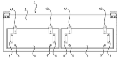
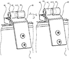
- FIG. 1 is a front view showing a vehicle control apparatus according to an embodiment of the present invention.
- a vehicle control device 1 shown in FIG. 1 is a control device for controlling the supply of electric power to a device (also referred to as a vehicle device) mounted on a vehicle such as a railway.
- the vehicle control device 1 includes a housing 2 and a lid 3.
- the housing 2 is a rectangular parallelepiped case for housing the vehicle control device 1 and mounting it on the vehicle.
- the housing 2 is installed under the floor of the vehicle, and an opening 21 (see FIG. 2) for inspecting or removing the control device housed in the housing 2 is formed on the side surface of the housing 2.
- a lid 3 is attached to the housing 2, and the opening 21 is covered with the lid 3.
- the lid 3 is supported by the connecting members 4A and 4B so that the opening 21 can be opened and closed.
- the lid 3 is made of a rectangular plate-shaped member and can be opened and closed with the upper side as an axis. As will be described below, the lid 3 can be opened and closed with the lower side raised, and can be removed from the opening 21 of the housing 2.
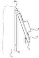
- FIG. 2 is an enlarged perspective view of the lid portion when the lid of the vehicle control device is opened.
- FIG. 3 is an enlarged side view of the lid portion when the lid of the vehicle control device is opened.
- the lid 3 shown in FIGS. 2 and 3 covers an opening 21 provided in the housing 2 and its frame 22.
- the lid 3 is supported by the casing 2 by connecting members 4A and 4B, and a latch 5 and a handle 6 are provided.
- the latch 5 is a stopper or a latch for fixing the lid 3 to the housing 2.
- the latch 5 is composed of a rotating shaft and an engaging body interlocking with the rotating shaft.
- the engaging body engages with the frame 22 of the housing 2, whereby the lid 3 is fixed to the housing 2. When the engagement body is disengaged, the lid 3 can be opened.
- the handle 6 is a member protruding from the lid 3 provided so that the lid 3 can be easily opened and closed.
- the lid 3 can be opened and closed by pulling the handle 6 toward the front side and lifting the lower side of the lid 3 with the engaging body of the latch 5 disengaged.
- the connecting members 4A and 4B are members that connect the housing 2 and the lid 3 so that the opening 21 can be opened and closed and removed by the lid 3.
- it is a member called a hinge or a hinge.
- the connecting members 4A and 4B are arranged in a straight line on the upper side of the lid 3 that faces in the horizontal direction, and connects the lid 3 and the housing 2 near the upper side of the frame 22. .
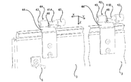
- FIG. 4 is an enlarged perspective view of the connecting member portion when the lid of the vehicle control device is opened. 4 includes a shaft support portion 42, shafts 41A and 41B, a bearing 43, a first extending portion 44, and a stopper 46.
- the shaft support portion 42 is a member that supports the shafts 41A and 41B.
- a columnar member formed integrally with the shafts 41A and 41B, a columnar shape in which the shafts 41A and 41B are fitted and fixed, or A cylindrical member corresponds to this.
- a cylindrical member is employed as the shaft support portion 42.
- the shaft support portion 42 is formed in a cylindrical shape, and one ends of the shafts 41A and 41B are inserted into the center of the cylinder.
- the shafts 41A and 41B are fixed inside the cylinder.
- a housing fixing portion is provided on a cylindrical side surface of the shaft support portion 42, and the shaft support portion 42 is connected to the housing 2 by the housing fixing portion.
- the shafts 41 ⁇ / b> A and 41 ⁇ / b> B are fixed to the housing 2 via the shaft support portion 42.
- the shafts 41A and 41B are cylindrical rods, and their lengths differ depending on the connecting members. That is, at least one of the connecting members 4A and 4B has a longer shaft than the other connecting members. For example, the shaft 41A of the connecting member 4A is longer than the shaft 41B of the connecting member 4B. Thereby, when attaching to the lid
- the shafts 41A and 41B are inserted into the bearing 43, and the bearing 43 is adjacent to the cylinder of the shaft support portion 42 in the axial direction of the shafts 41A and 41B.
- the bearing 43 is a cylindrical member similar to the shaft support portion 42.
- the bearing 43 supports the shafts 41A and 41B and allows the shafts 41A and 41B to be inserted and extracted. That is, the bearing 43 has a hole into which the shafts 41A and 41B are inserted, and can rotate with respect to the shaft support portion 42 in a state in which the shafts 41A and 41B are inserted.
- the bearing 43 is formed in a cylindrical shape, and a through-hole having an inner diameter substantially the same as that of the shafts 41A and 41B is formed in the cylinder.
- the first extending portion 44 is disposed so as to extend.
- the first extending portion 44 is a member for connecting the bearing 43 to the lid 3 and is formed so as to extend from the cylindrical side surface of the bearing 43 in a direction intersecting with the axial direction of the cylinder.
- the first extending portion 44 is integrally formed with the bearing 43 and is formed with a screw hole for fixing to the lid 3.
- the 1st extension part 44 and the bearing 43 are formed with a plate-shaped member (for example, sheet metal).
- a cylindrical bearing 43 formed by bending a plate-like member is disposed at one end, and a first extending portion 44 in which a screw hole for fixing to the lid 3 is formed at the other end is a cylinder of the bearing 43. It is arranged so as to protrude from.
- the protruding portion is planar, and is bent so that its tip follows the shape of the lid 3.
- the first extending portion 44 Since the first extending portion 44 is integral with the bearing 43, the first extending portion 44 can rotate with respect to the shaft support portion 42 in a state where the shafts 41A and 41B are inserted into the bearing 43. Since the shafts 41 ⁇ / b> A and 41 ⁇ / b> B are disposed in the vicinity of the upper side of the frame 22 surrounding the opening 21, the lid 3 connected to the first extending portion 44 can be opened and closed with the upper side of the opening 21 as the center. . When the lid 3 closes the opening 21, a stopper 46 is adjacent to the side of the first extension 44 (X direction shown in FIG. 4).
- the first extending portion 44 and the bearing 43 move in the axial direction of the shafts 41A and 41B (the X direction shown in FIG. 4, hereinafter, also simply referred to as the axial direction), and drop off from the shafts 41A and 41B.
- the stopper 46 is a plate-like structure having an L-shaped cross section, and one end is connected to the shaft support portion 42 and the other end is disposed on the side surface of the first extension portion 44. The stopper 46 restricts the movement in the axial direction adjacent to the first extending portion 44 in the axial direction.
- the fixed position is a position that does not interfere with the bearing 43. For example, it is outside the side surface of the cylinder of the bearing 43 (for example, the lower side of the cylinder, the Z direction shown in FIG. 4). For example, at one end, the plate-like portion is disposed along the surface of the housing 2.
- the other end of the stopper 46 is bent from the one end and extends in a direction crossing the axial direction of the shafts 41A and 41B.
- the stopper 46 has a plate-like portion that extends in a direction substantially parallel to the cylindrical bottom surface of the bearing 43.
- the plate-like portion is disposed adjacent to the first extending portion 44 in the axial direction and sandwiching the first extending portion 44 with the shaft support portion 42.
- the relationship between the opening and closing of the lid 3 and the stopper 46 will be described.
- FIG. 5 is an enlarged side view of the connecting member portion when the lid of the vehicle control device is closed.
- the stopper 46 shown in FIG. 5 is the first extension portion when the lid 3 is in a closed state, that is, when the first extension portion 44 is at an angle C shown in FIG. 5 with respect to the shaft support portion 42. 44 is adjacent in the axial direction. For this reason, the movement of the first extending portion 44 in the axial direction is restricted by the stopper 46.
- the bearing 43 formed integrally with the first extending portion 44 is adjacent to the shaft support portion 42 in the axial direction. For this reason, the movement of the bearing 43 in the axial direction is restricted by the shaft support portion 42.
- the first extending portion 44 and the bearing 43 are sandwiched between the shaft support portion 42 and the stopper 46 and cannot be removed in the axial direction. That is, the first extension 44 and the bearing 43 do not fall off the shaft 41A.
- the bearing 43 and the first extending portion 44 rotate with respect to the shaft support portion 42, and the first extending portion 44 is in FIG. 5 with respect to the shaft support portion 42.
- the angle formed by the first extending portion 44 with respect to the shaft support portion 42 is referred to as the opening angle of the first extending portion 44
- the first extending portion 44 It comes into contact with the guide surface 46A at the tip.
- the stopper 46 is not adjacent to the first extending portion 44 and the movement of the bearing 43 in the axial direction is not restricted.
- the stopper 46 is moved to the first extending portion. 44 is not completely adjacent.
- the opening angle of the first extending portion 44 is in the range between the angle C and the angle D, that is, in the angle range A (see FIG. 5), the bearing 43 and the first extending portion 44 are removed in the axial direction. However, when it is in the range of the angle D or more, that is, in the angle range B, these can be removed in the axial direction.
- the angle range B has an opening angle of the first extending portion 44, the lid 3 can be attached and detached. Below, the attachment and removal method of the lid
- FIG. 6 is a perspective view showing a positional relationship when the shaft of the connecting member of the vehicle control device is attached to the bearing.
- the lid 3 is attached by inserting the shafts 41A and 41B fixed to the housing 2 into the bearings 43 connected to the lid 3, respectively.
- the lid 3 is inclined with respect to the housing 2 so that the lid 3 is opened.
- the first extending portion 44 is in the angle range B described above.
- the longer shaft that is, the shaft 41A is inserted into the corresponding bearing 43.
- the shorter shaft 41B may not have the corresponding bearing 43 and the position thereof.
- the shaft 41B is inserted into the corresponding bearing 43.
- the shaft 41A is also inserted into the corresponding bearing 43 at the same time.
- the lid 3 is attached to the housing 2. In this way, the lid 3 is attached by inserting the bearings 43 in order from the longest one.
- the lid 3 is closed after the lid 3 is attached, the lid 3 fixed to the first extending portion 44 is not dropped from the shaft 41A by the stopper 46. Removal of the lid 3 is performed in the reverse procedure.
- the first extending portion 44 can be inclined to the angle range B by using the stopper 46.
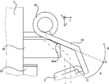
- FIG. 7 is a side view showing the relationship between the stopper of the vehicle control device and the first extending portion.
- the stopper 46 shown in FIG. 7 has a guide surface 46 ⁇ / b> A formed on a plate-like portion at the other end of the stopper 46.
- the guide surface 46A is formed in a shape having a surface substantially in the same direction as the surface of the first extension portion 44 in a state where the opening angle of the first extension portion 44 is in the angle range B.
- the guide surface 46A is substantially the same as the surface on the lid 3 side of the first extending portion 44 (the surface on the Z-axis side shown in FIG. 7) when the opening angle of the first extending portion 44 forms the angle D. They are formed at substantially the same inclination at the same position. For this reason, the bearing 42 and the first extending portion 44 are rotated so that the opening angle of the first extending portion 44 becomes the angle D, and the bearing 43 is moved in the direction to be extracted from the shaft 41A, thereby the first extending portion. When 44 and the stopper 46 are adjacent to each other in the direction intersecting the axis, the stopper 46 can support the first extending portion 44 by the guide surface 46A.
- the first extending portion 44 When the first extending portion 44 is placed on the guide surface 46A and the first extending portion 44 is supported by the guide surface 46A, the first extending portion 44 and the stopper 46 are adjacent to each other in the direction intersecting the axis. Therefore, the movement of the first extending portion 44 in the axial direction is not restricted by the stopper 46. Therefore, when the bearing 43 is inserted into the shaft 41 ⁇ / b> A or 41 ⁇ / b> B, the first extending portion 44 is placed on the guide surface 46 ⁇ / b> A so that the angle of the first extending portion 44 is inclined to an angle that allows insertion into the bearing 43. It is possible.
- the lid 3 can be easily attached by placing the first extending portion 44 on the guide surface 46A and sliding it, and inserting the shafts 41A and 41B into the corresponding bearings 43. Since the load on the lid 3 can be supported by the guide surface 46A, the burden on the operator is reduced.
- the connecting members 4A and 4B that connect the housing 2 and the lid 3 are respectively associated with the bearings 43 with the lid 3 inclined with respect to the housing 2.
- the lid 3 can be attached and detached by inserting or removing it. Therefore, compared with the conventional vehicle control device (for example, when the mounting and fixing device of Patent Document 1 is used), the vehicle control device 1 according to the embodiment can easily attach and detach the lid 3.
- the first extending portion 44 has a predetermined angular range with respect to the shaft support portion 42 (FIG. 5). 7 is arranged in the angle range A) shown in FIG. Therefore, the stopper 46 is adjacent to the first extending portion 44 in the axial direction. At this time, the first extending portion 44 and the bearing 43 are sandwiched between the shaft support portion 42 and the stopper 46. As a result, the vehicular control device 1 prevents the lid 3 from falling off the shaft 41A.
- the vehicle control device 1 is easy to attach the lid 3.
- the vehicle control apparatus 1 includes a plurality of connecting members, if the shafts of all the connecting members have the same length, it is necessary to simultaneously insert the shafts of all the connecting members into the bearing. According to this form, it is only necessary to insert the longer one of the connecting members 4A and 4B into the bearing 43. Since it is sufficient to insert into the bearing 43 in order from the longest shaft, the lid 3 can be easily attached. Also, if a long shaft is inserted first, the load on the lid 3 can be supported by the long shaft, so the burden on the operator is reduced.
- FIG. 8 is a perspective view showing a modification of the connecting member of the vehicle control device.
- the shaft support portion 42 has shafts 41C and 41D fixed thereto to support them and is connected to the second extending portion 45.
- the bearing 43 is connected to the stopper 46.
- the shaft 41C has a longer shaft length than the shaft 41D, and the shafts 41C and 41D are inserted into the bearings 43, respectively.
- the bearing 43 is a cylindrical member and supports the shafts 41C and 41D.
- a case fixing portion is provided on the side surface of the cylinder, and is fixed to the case 2 by this.
- the bearing 43 is adjacent to the shaft support portion 42 in the axial direction.
- the shaft support portion 42 is formed integrally with the second extending portion 45 and is fixed to the lid 3.
- it forms with a plate-shaped member (for example, sheet metal).
- a cylindrical shaft support portion 42 formed to be bent so as to surround the shafts 41C and 41D is disposed at one end, and a second extending portion 45 protruding from the cylindrical shaft support portion 42 is disposed at the other end. Be placed.
- the protruding portion has a flat shape, the tip thereof is bent, and a screw hole for fixing to the lid 3 is formed.
- the second extending portion 45 is adjacent to the stopper 46 when the lid 3 is in a closed state.
- the shape and arrangement of the stopper 46 are the same as in the first embodiment.
- One end of the stopper 46 is fixed to the housing 2 and connected to the bearing 43 via the housing 2.
- the other end of the stopper 46 is adjacent to the second extending portion 45 in the axial direction when the lid 3 is in a closed state. Further, when the lid 3 is in the opened state, it is not adjacent to the second extending portion 45.
- the lid 3 can be attached and detached while the lid 3 is inclined with respect to the housing 2. Further, the lid 3 is prevented from falling off the shaft 41C from the bearing 43 in a state where the lid 3 is closed with respect to the housing 2. Moreover, since what is necessary is just to insert in the bearing 43 in an order from the long thing of an axis
- the vehicle control device 1 may include one lid 3, and the lid 3 and the housing 2 may be coupled by three or more coupling members.
- the connection member of the said embodiment may be arrange
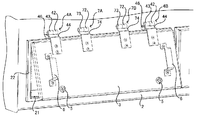
- FIG. 9 is a perspective view showing a modified example of the lid of the vehicle control device.
- the lid 3 shown in FIG. 9 is arranged so that the connecting members 4A, 7A, 7B, and 4B are aligned in the horizontal direction along the upper side, and these connecting members connect the casing 2 and the lid 3 together. is doing.
- the axes of the connecting members 4A, 7A, 7B, 4B are arranged substantially in a straight line.
- Connection members 4A and 4B are disposed at both ends of the above-mentioned side.
- the connecting members 4A and 4B are the same connecting members as those in the above-described embodiment, and the connecting members 7A and 7B include the shaft support portion 72, the bearing 73, and the third extending portion 74, but do not include the stopper 46. It is a connecting member.
- the connecting members 4A and 4B including the stopper 46 are disposed at both ends of the above-described side, and the connecting members 7A and 7B not including the stopper 46 are disposed inside thereof.
- the shafts of the connecting members 7A and 7B have the same length as the shaft 41B of the connecting member 4B according to the above embodiment.
- the axis of the connecting member 4A is longer than the axes of the other connecting members.
- the lid 3 can be easily attached because it is only necessary to insert the bearings 43 and 73 in order from the longest shaft.
- the connecting members 4A and 4B are arranged at both ends of the lid 3 as in the above embodiment. And compared with the case where it arrange
- FIG. 10 is a perspective view showing a modified example of the combination of connecting members used in the vehicle control device.
- the combination of the connecting members shown in FIG. 10 is a combination of the connecting member 7B that includes the shaft support portion 72, the bearing 73, and the third extending portion 74, and does not include the stopper 46, and the connecting member 4A of the above embodiment.
- the shaft 71B of the connecting member 7B has the same length as the shaft 41B of the connecting member 4B and is shorter than the shaft 41A of the connecting member 4A.
- any of the above embodiments can be variously modified within the scope of the gist of the present invention.
- the above embodiments are for explaining the present invention, and are not intended to limit the scope of the present invention.
- the cylindrical member that supports the shaft in a fixed state is described as the shaft support portion 42
- the cylindrical member that supports the shafts 41 ⁇ / b> A and 41 ⁇ / b> B so that they can be inserted and removed is described as the bearing 43.
- the shaft support portion 42 and the bearing 43 are both support members that support the shafts 41A and 41B, and may be referred to as support portions.
- the shaft may be inserted and removed from the shaft support portion 42, and this may be referred to as a support portion.
- any member or both members of the shaft support portion 42 and the bearing 43 support the shafts 41A and 41B in a rotatable manner.
- the shaft support portion 42 may rotatably support the shafts 41A and 41B, and the shaft may not be inserted or removed.
- the shaft support 42 and the bearing 43 are described separately from the shafts 41A and 41B.
- the present invention is not limited to this.
- Any member of the shaft support portion 42 and the bearing 43 may be formed integrally with the shafts 41A and 41B.
- a structure in which the shaft support portion 42 and the shaft 41A are integrated by cutting out a metal material may be adopted.
- the connection form of any member of the shaft support part 42 and the bearing 43 and the shafts 41A and 41B is not limited to the above embodiment.
- the shaft support portion 42 and the bearing 43 have a cylindrical shape, but the shapes of the shaft support portion 42 and the bearing 43 are not limited thereto.
- the present invention is a housing that is installed under the floor of a vehicle and has the opening 21 on the bottom surface side. You may apply to the control apparatus 1 for vehicles provided with the body 2 and the lid
- the present invention may be applied to the vehicle control device 1 that is provided on the roof and includes the housing 2 provided with the opening 21 on the upper surface side and the lid 3 that covers the opening 21.
- connection members 4A, 4B or 4C, 4D are arranged on the upper side of the lid 3.
- connection members 4A, 4B or 4C, 4D are provided on the lower side or the side sides. It may be arranged.
- the stopper 46 may be directly fixed to the shaft support portion 42.
- the shaft support portion 42 may be fixed to the cylindrical side surface of the shaft support portion 42, or the shaft support portion 42 and the stopper 46 may be integrally formed.
- 1 vehicle control device 2 housing, 21 opening, 22 frame, 3 lid, 4A, 4B, 4C, 4D connecting member, 41A, 41B, 41C, 41D shaft, 42 shaft support portion, 42A housing fixing portion, 43 bearing, 44 first extending portion, 45 second extending portion, 46 stopper, 46A guide surface, 5 latch, 6 handle, 7A, 7B connecting member, 71B shaft, 72 shaft support portion, 73 bearing, 74 third Extension part.
Landscapes
- Engineering & Computer Science (AREA)
- Mechanical Engineering (AREA)
- Casings For Electric Apparatus (AREA)
- Hinges (AREA)
- Motorcycle And Bicycle Frame (AREA)
- Vehicle Body Suspensions (AREA)
- Pivots And Pivotal Connections (AREA)
Abstract
Description
図1は本発明の実施の形態に係る車両用制御装置を示す正面図である。図1に示す車両用制御装置1は、鉄道等の車両に搭載した機器(車両機器ともいう)への電力の供給を制御するための制御装置である。車両用制御装置1は、筐体2と、蓋3とを備えている。
実施の形態1では、軸受43と第1延在部44が接続され、軸支持部42とストッパー46が連結された形態について説明したが、軸受43と軸支持部42とが置き換わった形態であってもよい。
軸受43は、円筒形の部材であり、軸41C,41Dを支持する。円筒の側面には、筐体固定部が設けられこれによって筐体2に固定されている。軸受43は軸方向に軸支持部42と隣接している。
上記実施の形態では、1つの蓋3に対して連結部材が2つある場合を説明したが、この数は任意である。例えば、車両用制御装置1が1つの蓋3を備え、3以上の数の連結部材で蓋3と筐体2とを連結してもよい。その場合に、蓋3両端に、上記実施の形態の連結部材が配置されてもよい。
Claims (7)
- 車両に搭載されて、前記車両を制御する車両用制御装置を収容する筐体と、
前記筐体に形成された開口を覆うための蓋と、
前記蓋と前記筐体とを、前記蓋で前記開口を開閉可能に連結する連結部材と、
を備え、
前記連結部材は、
前記筐体および前記蓋のいずれか一方に接続されて、軸を支持する第1の支持部と、
前記第1の支持部と前記軸の方向に隣接して、前記軸を支持する第2の支持部と、
前記第2の支持部から前記軸と交わる方向に延び、前記筐体および前記蓋の他方に接続される延在部と、
を有し、
前記第1の支持部および前記第2の支持部の少なくとも1つは、前記軸を回転可能に支持し、前記延在部および前記第2の支持部は、前記第1の支持部に対して回転可能であり、
前記第1の支持部および前記第2の支持部の少なくとも1つは、前記軸の挿入および抜出が可能であって、
前記第1の支持部および前記第2の支持部の少なくとも1つに前記軸が挿入されて前記第1の支持部および前記第2の支持部が隣接する状態で、前記延在部が前記第1の支持部に対して第1の角度範囲にある場合に、前記延在部と前記軸の方向に隣接せず、前記延在部が前記第1の支持部に対して第2の角度範囲にある場合に、前記延在部と前記軸の方向に隣接して前記第1の支持部とで前記延在部を前記軸の方向に挟み込む位置に配置される、ストッパーを有する、
車両用制御装置。 - 1つの前記蓋に対して複数の前記連結部材を備え、
前記複数の連結部材のうちの、少なくとも1つの前記連結部材の軸は、他のいずれか1つの前記連結部材の軸よりも長い、
請求項1に記載の車両用制御装置。 - 前記第1の角度範囲には、前記蓋が前記開口を閉じられている場合に、前記延在部が前記第1の支持部に対して形成する角度が含まれず、
前記第2の角度範囲には、前記蓋が前記開口を閉じられている場合に、前記延在部が前記第1の支持部に対して形成する角度が含まれる、
請求項1に記載の車両用制御装置。 - 前記ストッパーは、前記延在部が前記第1の支持部に対して特定の角度を形成し、かつ前記第1の支持部または前記第2の支持部のいずれか一方が前記軸の抜出方向に移動して前記延在部と前記ストッパーが前記軸と交わる方向に隣接する状態で、前記延在部を支持する形状に形成され、
前記特定の角度は、前記第1の角度範囲に含まれる、
請求項1に記載の車両用制御装置。 - 前記延在部は、平面状の板状部を有し、
前記ストッパーは、前記延在部が前記第1の支持部に対して前記特定の角度を形成した状態における前記板状部と平行な平面を有する形状に形成された、
請求項4に記載の車両用制御装置。 - 1つの前記蓋に対して複数の前記連結部材を備え、
前記複数の連結部材の軸は、水平方向かつ一直線上に並ぶように配置された、
請求項1に記載の車両制御装置。 - 前記連結部材と、
前記第1の支持部、前記第2の支持部および前記延在部を有し、前記ストッパーを有しない、他の連結部材と、
を1つの前記蓋に対して合計で少なくとも2以上備え、
前記合計で少なくとも2以上の、前記連結部材および前記他の連結部材のうち、少なくとも1つの前記軸は、他の連結部材の前記軸よりも長い、
請求項1に記載の車両用制御装置。
Priority Applications (8)
| Application Number | Priority Date | Filing Date | Title |
|---|---|---|---|
| EP13883227.4A EP2990293B1 (en) | 2013-04-24 | 2013-04-24 | Vehicle control apparatus |
| HK16102026.6A HK1214218B (zh) | 2013-04-24 | 车用控制装置 | |
| PCT/JP2013/062132 WO2014174624A1 (ja) | 2013-04-24 | 2013-04-24 | 車両用制御装置 |
| MX2015008749A MX358462B (es) | 2013-04-24 | 2013-04-24 | Aparato de control de vehiculo. |
| US14/758,674 US9470027B2 (en) | 2013-04-24 | 2013-04-24 | Vehicle control apparatus |
| JP2015513422A JP5925386B2 (ja) | 2013-04-24 | 2013-04-24 | 車両用制御装置 |
| CN201380075823.4A CN105143011B (zh) | 2013-04-24 | 2013-04-24 | 车用控制装置 |
| CA2898085A CA2898085C (en) | 2013-04-24 | 2013-04-24 | Cover connecting member for vehicle control apparatus housing |
Applications Claiming Priority (1)
| Application Number | Priority Date | Filing Date | Title |
|---|---|---|---|
| PCT/JP2013/062132 WO2014174624A1 (ja) | 2013-04-24 | 2013-04-24 | 車両用制御装置 |
Publications (1)
| Publication Number | Publication Date |
|---|---|
| WO2014174624A1 true WO2014174624A1 (ja) | 2014-10-30 |
Family
ID=51791232
Family Applications (1)
| Application Number | Title | Priority Date | Filing Date |
|---|---|---|---|
| PCT/JP2013/062132 Ceased WO2014174624A1 (ja) | 2013-04-24 | 2013-04-24 | 車両用制御装置 |
Country Status (7)
| Country | Link |
|---|---|
| US (1) | US9470027B2 (ja) |
| EP (1) | EP2990293B1 (ja) |
| JP (1) | JP5925386B2 (ja) |
| CN (1) | CN105143011B (ja) |
| CA (1) | CA2898085C (ja) |
| MX (1) | MX358462B (ja) |
| WO (1) | WO2014174624A1 (ja) |
Cited By (2)
| Publication number | Priority date | Publication date | Assignee | Title |
|---|---|---|---|---|
| CN105197114A (zh) * | 2015-09-21 | 2015-12-30 | 常州市海盈汽车部件有限公司 | 儿童汽车控制板装置 |
| JP2017210045A (ja) * | 2016-05-24 | 2017-11-30 | 株式会社総合車両製作所 | 車両床下構造及び鉄道車両 |
Families Citing this family (9)
| Publication number | Priority date | Publication date | Assignee | Title |
|---|---|---|---|---|
| US9528309B2 (en) * | 2012-10-15 | 2016-12-27 | Husqvarna Ab | Outdoor power equipment hood hinge |
| EP2990293B1 (en) * | 2013-04-24 | 2018-09-26 | Mitsubishi Electric Corporation | Vehicle control apparatus |
| DE102016117378B3 (de) * | 2016-09-15 | 2017-05-18 | Rittal Gmbh & Co. Kg | Scharnieranordnung für einen Schaltschrank |
| US10280664B1 (en) * | 2017-10-26 | 2019-05-07 | GM Global Technology Operations LLC | Hinge system for a storage bin in the cargo area of a vehicle |
| CN110877780B (zh) | 2018-09-06 | 2024-06-21 | 南通中集特种运输设备制造有限公司 | 门楣连接组件及包括其的开顶式集装箱 |
| DE102019103997B3 (de) * | 2019-02-18 | 2020-06-25 | Rittal Gmbh & Co. Kg | Scharnieranordnung für einen Schaltschrank und ein entsprechendes Verfahren |
| JP7170900B2 (ja) * | 2019-11-07 | 2022-11-14 | 三菱電機株式会社 | 車載機器 |
| FR3113693B1 (fr) * | 2020-08-31 | 2023-03-31 | Alstom Transp Tech | Charnière de trappe, véhicule et procédé d’assemblage associés |
| CN113738211B (zh) * | 2021-09-03 | 2022-12-13 | 上海机电工程研究所 | 可调互锁角度的可分离式铰链 |
Citations (4)
| Publication number | Priority date | Publication date | Assignee | Title |
|---|---|---|---|---|
| JPS5182222U (ja) * | 1974-12-24 | 1976-07-01 | ||
| JPS58116461U (ja) * | 1982-02-04 | 1983-08-09 | 三菱電機株式会社 | 車輌用制御箱 |
| JPH0930413A (ja) | 1995-07-20 | 1997-02-04 | Kawasaki Heavy Ind Ltd | 車両用側ふさぎ板の取付固定装置 |
| JP2008038953A (ja) * | 2006-08-02 | 2008-02-21 | Nippon Sharyo Seizo Kaisha Ltd | 車両 |
Family Cites Families (19)
| Publication number | Priority date | Publication date | Assignee | Title |
|---|---|---|---|---|
| US2677147A (en) | 1950-10-07 | 1954-05-04 | Int Harvester Co | Separable hinge |
| GB1521690A (en) | 1974-12-11 | 1978-08-16 | Ici Ltd | Production of isocyanates |
| JPS61127278U (ja) * | 1985-01-29 | 1986-08-09 | ||
| JPH06180085A (ja) * | 1992-12-14 | 1994-06-28 | Mitsubishi Electric Corp | 2部品のはめ込み式組立構造 |
| JPH08270300A (ja) | 1995-03-30 | 1996-10-15 | Showa Alum Corp | 蝶番を用いた扉等の取付け構造 |
| CN2295033Y (zh) * | 1996-07-23 | 1998-10-21 | 杜德斌 | 易安装脱卸合页 |
| DE29711491U1 (de) | 1997-07-01 | 1997-09-04 | Brügge, Heinrich, 33604 Bielefeld | Scharniersatz |
| US6070297A (en) | 1997-12-29 | 2000-06-06 | Square D Company | Concealed hinge for removable cover enclosures |
| US6244647B1 (en) * | 1999-11-18 | 2001-06-12 | Visteon Corporation | Controlled rate hinge responsive to weight |
| US20070205334A1 (en) * | 2003-05-09 | 2007-09-06 | Boyean Kim | Office work apparatus for cars |
| DE102004025655B3 (de) * | 2004-05-26 | 2005-10-27 | Lisa Dräxlmaier GmbH | Klapp-Deckel eines Gehäuses |
| TWM265263U (en) * | 2004-07-08 | 2005-05-21 | Pei-Shiou Huang | In-vehicle removable mounting rack |
| JP4772541B2 (ja) * | 2006-03-14 | 2011-09-14 | 株式会社ニフコ | 両開きリッド装置及びセンターコンソールボックス |
| DE102007061055B4 (de) * | 2007-12-18 | 2022-06-15 | Dr. Ing. H.C. F. Porsche Aktiengesellschaft | Klappenanordnung |
| US8701953B2 (en) * | 2009-10-09 | 2014-04-22 | Raytheon Company | Electronic flight bag mounting system |
| FR2979859B1 (fr) * | 2011-09-13 | 2014-01-31 | Delphi Tech Inc | Module de controle integrant un dispositif d'aide a l'assemblage. |
| DE112012006568T5 (de) * | 2012-06-20 | 2015-03-12 | Faurecia Interior Systems India Pvt. Ltd. | Zum Öffnen in zwei verschiedene Richtungen eingerichtete Aufbewahrungsvorrichtung |
| CN202745570U (zh) * | 2012-07-26 | 2013-02-20 | 宁波永发集团有限公司 | 能对门体开启角度进行限定的外门铰链结构 |
| EP2990293B1 (en) * | 2013-04-24 | 2018-09-26 | Mitsubishi Electric Corporation | Vehicle control apparatus |
-
2013
- 2013-04-24 EP EP13883227.4A patent/EP2990293B1/en active Active
- 2013-04-24 US US14/758,674 patent/US9470027B2/en active Active
- 2013-04-24 JP JP2015513422A patent/JP5925386B2/ja active Active
- 2013-04-24 WO PCT/JP2013/062132 patent/WO2014174624A1/ja not_active Ceased
- 2013-04-24 CN CN201380075823.4A patent/CN105143011B/zh active Active
- 2013-04-24 MX MX2015008749A patent/MX358462B/es active IP Right Grant
- 2013-04-24 CA CA2898085A patent/CA2898085C/en active Active
Patent Citations (4)
| Publication number | Priority date | Publication date | Assignee | Title |
|---|---|---|---|---|
| JPS5182222U (ja) * | 1974-12-24 | 1976-07-01 | ||
| JPS58116461U (ja) * | 1982-02-04 | 1983-08-09 | 三菱電機株式会社 | 車輌用制御箱 |
| JPH0930413A (ja) | 1995-07-20 | 1997-02-04 | Kawasaki Heavy Ind Ltd | 車両用側ふさぎ板の取付固定装置 |
| JP2008038953A (ja) * | 2006-08-02 | 2008-02-21 | Nippon Sharyo Seizo Kaisha Ltd | 車両 |
Cited By (2)
| Publication number | Priority date | Publication date | Assignee | Title |
|---|---|---|---|---|
| CN105197114A (zh) * | 2015-09-21 | 2015-12-30 | 常州市海盈汽车部件有限公司 | 儿童汽车控制板装置 |
| JP2017210045A (ja) * | 2016-05-24 | 2017-11-30 | 株式会社総合車両製作所 | 車両床下構造及び鉄道車両 |
Also Published As
| Publication number | Publication date |
|---|---|
| JP5925386B2 (ja) | 2016-05-25 |
| MX358462B (es) | 2018-08-22 |
| HK1214218A1 (zh) | 2016-07-22 |
| JPWO2014174624A1 (ja) | 2017-02-23 |
| US9470027B2 (en) | 2016-10-18 |
| EP2990293B1 (en) | 2018-09-26 |
| CN105143011A (zh) | 2015-12-09 |
| CN105143011B (zh) | 2017-09-19 |
| EP2990293A4 (en) | 2016-04-27 |
| CA2898085C (en) | 2017-07-25 |
| US20150337581A1 (en) | 2015-11-26 |
| MX2015008749A (es) | 2015-11-13 |
| CA2898085A1 (en) | 2014-10-30 |
| EP2990293A1 (en) | 2016-03-02 |
Similar Documents
| Publication | Publication Date | Title |
|---|---|---|
| JP5925386B2 (ja) | 車両用制御装置 | |
| EP2626234A2 (en) | Charging station for use in charging electrically powered vehicles | |
| US7942459B2 (en) | Mounting device for a line replaceable unit in an aircraft and a method for using the same | |
| JP5651409B2 (ja) | 火災感知器用点検ボックス | |
| US20160208521A1 (en) | Bowden cable bearing for a motor vehicle lock | |
| EP2397371B1 (en) | Dashboard of a vehicle, in particular of an industrial vehicle | |
| CN205422299U (zh) | 连接系统 | |
| JP4961010B2 (ja) | 脱着機構及びそれを用いた電子装置 | |
| HK1214218B (zh) | 车用控制装置 | |
| JP2014104813A (ja) | スライドドアの取付け位置調整治具 | |
| JP4438996B2 (ja) | 装置の筐体構造およびサブカバー開閉構造 | |
| JP4555315B2 (ja) | 収納ボックス | |
| JP4774385B2 (ja) | 圧縮空気除湿装置の配電盤 | |
| WO2011092730A1 (ja) | 表示機器 | |
| JP2009522165A (ja) | 航空機操縦室開閉ガラス窓のケーブル保護誘導装置 | |
| JP5914105B2 (ja) | 扉取付構造及びそれを備えた鉄道車両の機器収納箱 | |
| JP4740044B2 (ja) | 機器収納キャビネット | |
| WO2019180918A1 (ja) | 鉄道車両用制御装置 | |
| JP3218769U (ja) | 溝蓋用受枠 | |
| JP6925820B2 (ja) | スイッチギヤの換気装置 | |
| CN107639652A (zh) | 一种自动化机械手方便拆卸的防护装置 | |
| JP4977578B2 (ja) | ドアクローザ | |
| JP3141276U (ja) | 電気機器収納箱 | |
| JP2009289811A (ja) | 機器筐体 | |
| JP3122236U (ja) | パッチパネルのパネルとブラケット構造 |
Legal Events
| Date | Code | Title | Description |
|---|---|---|---|
| WWE | Wipo information: entry into national phase |
Ref document number: 201380075823.4 Country of ref document: CN |
|
| 121 | Ep: the epo has been informed by wipo that ep was designated in this application |
Ref document number: 13883227 Country of ref document: EP Kind code of ref document: A1 |
|
| ENP | Entry into the national phase |
Ref document number: 2015513422 Country of ref document: JP Kind code of ref document: A |
|
| WWE | Wipo information: entry into national phase |
Ref document number: 14758674 Country of ref document: US |
|
| WWE | Wipo information: entry into national phase |
Ref document number: MX/A/2015/008749 Country of ref document: MX |
|
| ENP | Entry into the national phase |
Ref document number: 2898085 Country of ref document: CA |
|
| WWE | Wipo information: entry into national phase |
Ref document number: 2013883227 Country of ref document: EP |
|
| NENP | Non-entry into the national phase |
Ref country code: DE |