WO2014174717A1 - エンジンシステムおよびそれを備えた車両 - Google Patents
エンジンシステムおよびそれを備えた車両 Download PDFInfo
- Publication number
- WO2014174717A1 WO2014174717A1 PCT/JP2013/082078 JP2013082078W WO2014174717A1 WO 2014174717 A1 WO2014174717 A1 WO 2014174717A1 JP 2013082078 W JP2013082078 W JP 2013082078W WO 2014174717 A1 WO2014174717 A1 WO 2014174717A1
- Authority
- WO
- WIPO (PCT)
- Prior art keywords
- detection
- engine
- detection body
- ignition
- energization
- Prior art date
- Legal status (The legal status is an assumption and is not a legal conclusion. Google has not performed a legal analysis and makes no representation as to the accuracy of the status listed.)
- Ceased
Links
Images





Classifications
-
- F—MECHANICAL ENGINEERING; LIGHTING; HEATING; WEAPONS; BLASTING
- F02—COMBUSTION ENGINES; HOT-GAS OR COMBUSTION-PRODUCT ENGINE PLANTS
- F02P—IGNITION, OTHER THAN COMPRESSION IGNITION, FOR INTERNAL-COMBUSTION ENGINES; TESTING OF IGNITION TIMING IN COMPRESSION-IGNITION ENGINES
- F02P7/00—Arrangements of distributors, circuit-makers or -breakers, e.g. of distributor and circuit-breaker combinations or pick-up devices
- F02P7/06—Arrangements of distributors, circuit-makers or -breakers, e.g. of distributor and circuit-breaker combinations or pick-up devices of circuit-makers or -breakers, or pick-up devices adapted to sense particular points of the timing cycle
- F02P7/067—Electromagnetic pick-up devices, e.g. providing induced current in a coil
-
- F—MECHANICAL ENGINEERING; LIGHTING; HEATING; WEAPONS; BLASTING
- F02—COMBUSTION ENGINES; HOT-GAS OR COMBUSTION-PRODUCT ENGINE PLANTS
- F02D—CONTROLLING COMBUSTION ENGINES
- F02D41/00—Electrical control of supply of combustible mixture or its constituents
- F02D41/009—Electrical control of supply of combustible mixture or its constituents using means for generating position or synchronisation signals
-
- F—MECHANICAL ENGINEERING; LIGHTING; HEATING; WEAPONS; BLASTING
- F02—COMBUSTION ENGINES; HOT-GAS OR COMBUSTION-PRODUCT ENGINE PLANTS
- F02P—IGNITION, OTHER THAN COMPRESSION IGNITION, FOR INTERNAL-COMBUSTION ENGINES; TESTING OF IGNITION TIMING IN COMPRESSION-IGNITION ENGINES
- F02P5/00—Advancing or retarding ignition; Control therefor
- F02P5/04—Advancing or retarding ignition; Control therefor automatically, as a function of the working conditions of the engine or vehicle or of the atmospheric conditions
- F02P5/145—Advancing or retarding ignition; Control therefor automatically, as a function of the working conditions of the engine or vehicle or of the atmospheric conditions using electrical means
- F02P5/15—Digital data processing
- F02P5/1502—Digital data processing using one central computing unit
- F02P5/1506—Digital data processing using one central computing unit with particular means during starting
-
- G—PHYSICS
- G01—MEASURING; TESTING
- G01D—MEASURING NOT SPECIALLY ADAPTED FOR A SPECIFIC VARIABLE; ARRANGEMENTS FOR MEASURING TWO OR MORE VARIABLES NOT COVERED IN A SINGLE OTHER SUBCLASS; TARIFF METERING APPARATUS; MEASURING OR TESTING NOT OTHERWISE PROVIDED FOR
- G01D5/00—Mechanical means for transferring the output of a sensing member; Means for converting the output of a sensing member to another variable where the form or nature of the sensing member does not constrain the means for converting; Transducers not specially adapted for a specific variable
- G01D5/12—Mechanical means for transferring the output of a sensing member; Means for converting the output of a sensing member to another variable where the form or nature of the sensing member does not constrain the means for converting; Transducers not specially adapted for a specific variable using electric or magnetic means
- G01D5/244—Mechanical means for transferring the output of a sensing member; Means for converting the output of a sensing member to another variable where the form or nature of the sensing member does not constrain the means for converting; Transducers not specially adapted for a specific variable using electric or magnetic means influencing characteristics of pulses or pulse trains; generating pulses or pulse trains
- G01D5/245—Mechanical means for transferring the output of a sensing member; Means for converting the output of a sensing member to another variable where the form or nature of the sensing member does not constrain the means for converting; Transducers not specially adapted for a specific variable using electric or magnetic means influencing characteristics of pulses or pulse trains; generating pulses or pulse trains using a variable number of pulses in a train
- G01D5/2454—Encoders incorporating incremental and absolute signals
- G01D5/2455—Encoders incorporating incremental and absolute signals with incremental and absolute tracks on the same encoder
- G01D5/2457—Incremental encoders having reference marks
-
- G—PHYSICS
- G01—MEASURING; TESTING
- G01P—MEASURING LINEAR OR ANGULAR SPEED, ACCELERATION, DECELERATION, OR SHOCK; INDICATING PRESENCE, ABSENCE, OR DIRECTION, OF MOVEMENT
- G01P3/00—Measuring linear or angular speed; Measuring differences of linear or angular speeds
- G01P3/42—Devices characterised by the use of electric or magnetic means
- G01P3/44—Devices characterised by the use of electric or magnetic means for measuring angular speed
- G01P3/48—Devices characterised by the use of electric or magnetic means for measuring angular speed by measuring frequency of generated current or voltage
- G01P3/481—Devices characterised by the use of electric or magnetic means for measuring angular speed by measuring frequency of generated current or voltage of pulse signals
-
- F—MECHANICAL ENGINEERING; LIGHTING; HEATING; WEAPONS; BLASTING
- F02—COMBUSTION ENGINES; HOT-GAS OR COMBUSTION-PRODUCT ENGINE PLANTS
- F02D—CONTROLLING COMBUSTION ENGINES
- F02D41/00—Electrical control of supply of combustible mixture or its constituents
- F02D41/009—Electrical control of supply of combustible mixture or its constituents using means for generating position or synchronisation signals
- F02D2041/0092—Synchronisation of the cylinders at engine start
-
- Y—GENERAL TAGGING OF NEW TECHNOLOGICAL DEVELOPMENTS; GENERAL TAGGING OF CROSS-SECTIONAL TECHNOLOGIES SPANNING OVER SEVERAL SECTIONS OF THE IPC; TECHNICAL SUBJECTS COVERED BY FORMER USPC CROSS-REFERENCE ART COLLECTIONS [XRACs] AND DIGESTS
- Y02—TECHNOLOGIES OR APPLICATIONS FOR MITIGATION OR ADAPTATION AGAINST CLIMATE CHANGE
- Y02T—CLIMATE CHANGE MITIGATION TECHNOLOGIES RELATED TO TRANSPORTATION
- Y02T10/00—Road transport of goods or passengers
- Y02T10/10—Internal combustion engine [ICE] based vehicles
- Y02T10/40—Engine management systems
Definitions
- the present invention relates to an engine system provided with an engine (internal combustion engine) that sparks a spark plug in a combustion chamber to burn fuel, and a vehicle provided with the engine system.
- an engine internal combustion engine
- the fuel injection type engine is provided with a crank angle detection device for detecting the rotation angle of the crankshaft.
- the crank angle detection device includes a rotor that rotates with the crankshaft, and a pickup that generates a detection signal as the rotor rotates. Detection teeth are provided at equal intervals on the outer periphery of the rotor. The detection signal output by the pickup fluctuates as the detection teeth pass. By shaping this detection signal, a crank pulse is generated.
- conventional crank angle detection devices there is one in which a missing tooth position in which a detection tooth is missing is provided at one position on the outer periphery of a rotor. Since no crank pulse is generated at this missing tooth position, the crank pulse interval becomes long before and after the missing tooth position. Thereby, the reference rotational position of the crankshaft can be obtained.
- the crank angle can be determined by counting the crank pulses (counting the detected teeth) based on the reference rotational position. Fuel injection control and ignition control are performed based on the crank angle thus determined.
- Patent Document 1 discloses a crank angle detection device in which a plurality of convex portions are arranged on the outer peripheral surface of a rotor so that the rear end positions are equally spaced, and the convex portions are detected by a pickup to generate crank pulses. ing.
- One of the plurality of projections has a length from the rear end to the front end that is longer than the other projections, and is a projection that indicates a reference angle of the crank angle (hereinafter referred to as "reference projection"). It is assumed.
- the reference convex portion is disposed immediately before the crank angle (top dead center position) corresponding to the top dead center of the piston.
- the pick-up generates a negative pulse at each front end of the plurality of protrusions and a positive pulse at the rear end of each protrusion.
- the negative pulse and the positive pulse are shaped into the front end position pulse and the rear end position pulse, respectively.
- An interrupt to the CPU is generated at the generation timing of the front end position pulse, whereby the generation interval of the front end position pulse is measured.
- an interrupt to the CPU is generated at the generation timing of the rear end position pulse, whereby the generation interval of the rear end position pulse is measured.
- the rear end position of the reference convex portion is based on the ratio of the generation interval of the front end position pulse and the generation interval of the rear end position pulse. Is detected. In synchronization with this, energization of the ignition coil is started. Then, when the rear end position of the convex portion next to the reference convex portion is detected, the energization to the ignition coil is stopped, spark discharge of the spark plug is generated, and the first explosion ignition is performed. Thus, the correct crank angle can be detected before the crankshaft makes one rotation, and an appropriate first firing timing can be given.
- a rotor for crank angle detection is provided with a single protrusion, and based on the detection of the protrusion, the energization of the ignition coil and the spark discharge of the spark plug are controlled. Therefore, when the cranking is started, the ignition control can be started promptly, so the startability is good.
- the plurality of convex portions are disposed around the rotor, and each has a function, so the convex portion of which function is the convex portion Ignition control can not be started in a period before it is determined whether the More specifically, for example, a configuration is provided in which a signal serving as a reference is output from, for example, projections or chipped teeth having a shape different from that of other projections.
- the convex portion is determined based on the reference signal. Therefore, the ignition control can not be started until the reference signal is output.
- a signal serving as a reference may be output only after crossing over the compression top dead center from the start of cranking by the starter motor. Therefore, since it takes a long time to start ignition control, the startability of the engine is poor.
- the starter motor may be designed as small as possible so as to obtain an output capable of reliably crossing the first compression top dead center and rotating the crankshaft.
- the arrangement for generating a reference signal such as the aforementioned missing teeth is usually arranged such that the rotational speed of the crankshaft is detected by the pickup at a stable crank angle. With this configuration, the above-described problem in the prior art of Patent Document 1 does not occur. However, since the stop position of the engine is often before the compression stroke, in a normal arrangement such as a missing tooth, it is a reference only after exceeding the first compression top dead center immediately after starting cranking. Often it is not possible to generate a signal.
- an object of the present invention is to provide an engine system capable of igniting the engine in the first compression stroke after the start of cranking to improve startability.
- an engine having a crankshaft, a rotating member that rotates around a rotation axis with the crankshaft, a plurality of first detection bodies provided on the rotating member, and a first member similarly provided on the rotating member
- An engine system includes a second detector, first and second detectors that respectively detect first and second detectors, and an ignition controller.
- the engine includes a spark plug that sparks in a combustion chamber, a spark coil that stores energy to be supplied to the spark plug, and a crankshaft.
- the plurality of first detection bodies are arranged at equal intervals along the rotation direction of the rotating member.
- the second detection body is disposed at a position different from the first detection body in the direction along the rotation axis.
- the first detection means has a first detection area at a fixed position on a track through which the first detection body passes as the rotation member rotates, and the first detection area of the first detection body passes Output a detection signal that fluctuates along with the
- the second detection means has a second detection area at a fixed position on a track through which the second detection body passes as the rotating member rotates, and the second detection area of the second detection body passes And outputs a detection signal that fluctuates along with the second detection object in the compression stroke of the engine.
- the ignition control means starts energization control for energizing the ignition coil in response to the detection of the second detection body by the second detection means.
- the "energization control" means control for energizing the ignition coil.
- the energization control includes detection or determination of the energization start timing to the ignition coil as well as energization to the ignition coil.
- the start of energization control is the start of control for determining the energization start timing.
- the start of the energization control is the start of energization of the ignition coil.
- the rotating member is provided with the plurality of first detection bodies and the second detection bodies.
- the plurality of first detection bodies are arranged at equal intervals along the rotational direction of the rotating member.
- the second detection body is disposed at a position different from the first detection body in the direction along the rotation axis of the rotation member. That is, the second detection body is provided on the rotation member at a position shifted from the first detection body along the rotation axis of the rotation member.
- the second detection body passes through the second detection area of the second detection means in the compression stroke of the engine.
- energization control for energizing the ignition coil is started. Therefore, the energization control to the ignition coil can be started in the first compression stroke after engine cranking is started. This can improve the engine startability in the first compression stroke.
- control of the engine thereafter can also be started promptly.
- the second detection body is arranged to be offset from the first detection body along the rotation axis direction, and the second detection means for detecting the second detection body detects the first detection body.
- the energization timing of the ignition coil is defined by the rotational position of the crankshaft. Therefore, it is preferable that the second detection body be detected by the second detection means at or immediately before the rotational position of the crankshaft is a position where energization of the ignition coil should be started. That is, it is preferable that the relative position between the second detection area of the second detection means and the second detection body be determined so as to satisfy this condition. Therefore, for example, the arrangement of the second detection means can be determined, and the arrangement of the second detection body on the rotating member can be determined according to the arrangement. Therefore, the degree of freedom of the arrangement of the second detection means is high, and the design conditions for arranging the second detection means are mild. Thus, for example, the second detection means can be arranged by selecting a space around the rotation member.
- the plurality of first detection bodies include an ignition detection body that provides ignition timing of the spark plug, and the ignition control means detects the ignition detection body by the first detection means. In response to the switching, the ignition coil is de-energized to spark the spark plug.
- the second detection means detects the second detection body
- energization control to the ignition coil is started, and thereafter, when the first detection means detects the ignition detection body, the energization to the ignition coil is stopped.
- the spark plug sparks and discharges. As a result, the fuel in the combustion chamber of the engine is ignited and explodes.
- the arrangement of the second detection body and the second detection area is preferably set such that the second detection body is detected by the second detection means immediately before the first detection means detects the ignition detection body.
- the plurality of first detectors may include an energization start detector and an ignition detector.
- the arrangement of the second detection body and the second detection area is such that the second detection body is detected by the second detection means simultaneously with or immediately before the timing at which the first detection means detects the energization start detection body. It is preferable to set to. In the case of the arrangement in which the second detection body is detected by the second detection means immediately before the timing when the first detection means detects the energization start detection body, any other detection may be performed after the second detection means detects the second detection body.
- the first detection means detect the energization start detection body earlier than the first detection body.
- the energization start detector may be disposed on the rotating member so as to pass through the first detection region immediately before the ignition detector.
- the first detection body that first passes the first detection area after the energization start detection body passes the first detection area may be the ignition detection body.
- the arrangement is determined such that the second detection body is detected by the second detection means at the same time as the energization start detection body is detected by the first detection means, and the second detection body is detected by the second detection means In response to (in synchronization with), the energization of the ignition coil may be started.
- the second detection body is disposed so as to be detected by the second detection means before the energization start detection body is detected by the first detection means, and the detection of the second detection body is waited for before the detection of the first detection body.
- the ignition coil may be energized.
- the second detection body be detected by the second detection means at a timing between the detection timing of the energization start detection body and the detection timing of the first detection body immediately before that. That is, the second detection body is detected by the second detection means before a first detection body is detected by the first detection means, and then another first detection body is detected by the first detection means. Then, the arrangement in which the detection of the start of energization is detected earlier than any other first detection object is preferable.
- the “energization control” in the above case is started in response to (in synchronization with) the detection of the first detection body, which is started in response to (in synchronization with) the detection of the second detection body, and the detection of the current supply start detection body. And energizing the ignition coil. Such “energization control” is started in response to the detection of the second detection body.
- the second detection body is disposed at the same position as any one of the plurality of first detection bodies in the circumferential direction of the rotating member. According to this configuration, when the first detection means detects the first detection body, even if the second detection body responds simultaneously (that is, the second detection body is also detected), the first detection is performed. The output signal of the means is not significantly affected. In addition, since the first detection body and the second detection body may be disposed close to each other, the size of the rotation member in the rotation axis direction can be reduced. Thereby, the engine system can be miniaturized.
- the second detection body is integrated with any one of the plurality of first detection bodies. According to this configuration, the engine can be stably controlled with less erroneous detection, and the rotating member can be further miniaturized. Further, in the manufacturing process, when the first detection body is arranged, since the second detection body can be arranged at the same time, the number of manufacturing steps can be reduced.
- the first detection means and the second detection means are disposed at different positions with respect to the direction along the rotation axis. With this configuration, since the first detection area and the second detection area can be easily shifted in the rotation axis direction, erroneous detection can be reduced and the arrangement of the first and second detection means can be facilitated.
- the first and second detection means may be disposed at the same position with respect to the rotational direction of the rotating member, or may be disposed at different positions. From the viewpoint of easiness of securing the arrangement space, the first and second detection means are preferably arranged at different positions with respect to the rotational direction of the rotary member. As described above, as long as the relative position between the second detection area and the second detection body is appropriately set, the second detection area can be freely disposed around the rotating member. Therefore, the second detection means may be arranged by selecting a space which is easy to arrange.
- the first detection area and the second detection area are arranged at different positions in the circumferential direction of the rotating member.
- the first and second detection means can be easily disposed at different positions in the circumferential direction, so that, for example, a design for downsizing the engine system is facilitated.
- the rotating member includes a cylindrical portion having a width in a direction along the rotation axis, and the first detection body is at a central position in the width direction of the cylindrical portion. It is disposed to be shifted in one direction along the rotation axis. According to this configuration, since the first detection body and the second detection body can be disposed by effectively utilizing the width of the cylindrical portion, the width of the cylindrical portion can be reduced. Thereby, the rotating member can be miniaturized, and as a result, the engine system can be miniaturized.
- the second detection body is arranged to be shifted in the other direction along the rotation axis with respect to the center position in the width direction of the cylindrical portion.
- the first and second detection bodies are distributed on both sides with respect to the center in the width direction of the cylindrical portion.
- the width of the cylindrical portion can be reduced, so that the rotating member can be miniaturized.
- “distributed to both sides” means that the respective center-of-gravity positions are located on the opposite sides of the center in the width direction of the cylindrical portion. Therefore, at least one of the first detection body and the second detection body may be disposed across the center in the width direction of the cylindrical portion.
- the second detection body passes the second detection area when the second detection area is a rotational position immediately before a top dead center position of the crankshaft. Is located in With this configuration, when the engine is started, energization of the ignition coil can be started before the rotational position of the crankshaft reaches the top dead center position, whereby the engine can be started quickly. In addition, before the rotational position of the crankshaft reaches the top dead center position, a reference regarding the rotational position of the crankshaft is obtained, and in accordance therewith, it is possible to determine the first detection body. As a result, the engine can be started quickly.
- the crankshaft When the rotational position of the crankshaft is immediately before the compression top dead center position, the load required to rotate the crankshaft (cranking load) is maximized. Therefore, when the engine is stopped, the crankshaft is stopped at a rotational position before the compression top dead center with high probability. Therefore, the first top dead center position after engine start is almost always the compression top dead center position. Therefore, since the second detection body is detected by the second detection means immediately before the first top dead center position after engine start, ignition control can be promptly started to quickly start the engine. That is, the engine is preferably configured such that the first top dead center position after the start of cranking is the compression top dead center position.
- the “rotational position immediately before the top dead center position” is a rotational position within a predetermined range before the top dead center, and more specifically, within the rotational position range within 180 degrees immediately before the top dead center position.
- the position of That is, in a four-stroke engine in which one cycle consists of four strokes of intake, compression, explosion and exhaust, the rotational position of the crankshaft in the compression stroke or exhaust stroke corresponds.
- the "rotational position immediately before the top dead center position” is the rotational position within 90 degrees immediately before the top dead center position, that is, the rotational position of the crankshaft in the second half of the compression stroke or the second half of the exhaust stroke. May be
- the engine system is provided on the rotating member so as to pass through the first detection area, and the first detection body and the second detection system are based on an output signal of the first detection means.
- the first detection body is detected based on the reference position detection unit or the second detection body based on the reference position detection unit distinguishable from the detection body, and the output signals of the first detection means and the second detection means.
- the plurality of first detection bodies further include an energization start detection body for giving timing to start energization of the ignition coil, and the detection body discrimination means further includes start detection of the engine.
- the detection of the energization start detector is performed based on which of the second detector and the reference position detector is detected earlier, whichever is earlier.
- the energization start detector is determined based on the reference position detection unit without using the output of the second detection unit, and the ignition control unit determines by the detection unit determination unit In response to (in synchronization with) the detection of the energization start detection body, energization of the ignition coil is started.
- the reference position detection unit is provided separately from the second detection body, if any one of the second detection body and the reference position detection unit is detected, it is possible to determine the first detection body Become. After the start of the engine start, before the engine is completed, the energization start detection body and the ignition detection body based on which of the second detection body and the reference position detection unit is detected earlier. Is determined. As a result, when the second detection body is detected first after the engine is started, energization start detection is performed based on the second detection body, and when the reference position detection unit is detected first, based on the reference position detection unit. The body and the ignition detector are determined.
- the rotation of the crankshaft is not always stable immediately before the top dead center position where the reference convex portion is provided.
- the rotation of the cranking axis is the most unstable. Therefore, the detection of the reference convex portion based on the position immediately before the top dead center is not always stable, and accordingly, accurate engine control may be inhibited, which may result in deterioration of the operating efficiency of the engine.
- the second detection body with priority given to starting the ignition control early when starting the engine, after the engine start is complete, not the second detection body, but the reference position detection unit It is preferable to set it as the standard for. As a result, the determination accuracy of the first detection body can be enhanced, and accordingly, accurate and efficient engine control can be realized.
- the second detection body is detected immediately before (or shortly before) detection of the energization start detection body first. Therefore, the energization start detection body is promptly determined to the ignition coil. Power can be started. Thereby, the engine can be started quickly.
- the reference position detection unit when the rotational position of the crankshaft is in the vicinity of a bottom dead center position (a predetermined range so as to include the bottom dead center position), the reference position detection unit The rotating member is disposed to pass through. Since the rotation of the crankshaft is stable near the bottom dead center position, the reference position detection unit can be detected reliably.
- the reference position detection unit be disposed so as to be detected by the first detection unit after passing through the first detection region in the expansion stroke or intake stroke of the engine.
- One embodiment of the present invention provides a vehicle having an engine system having the above-described features and powered by the engine.
- FIG. 1 is an illustrative side view for describing a configuration of a motorcycle that is an example of a straddle-type vehicle to which an engine system according to an embodiment of the present invention is applied.
- FIG. 2 is a perspective view showing a configuration example of a handle of the motorcycle.
- FIG. 3 is a horizontal sectional view of the power unit of the motorcycle.
- FIG. 4 is a schematic view for explaining a configuration related to an engine provided in the power unit.
- FIG. 5 is a schematic side view for explaining a configuration for detecting a rotational position of a crankshaft of the engine, that is, a crank angle.
- FIG. 6 is a schematic view in which an outer peripheral surface of a rotor for detecting a crank angle of the engine is developed.
- FIG. 1 is an illustrative side view for describing a configuration of a motorcycle that is an example of a straddle-type vehicle to which an engine system according to an embodiment of the present invention is applied.
- FIG. 2
- FIG. 7 is a block diagram for explaining an electrical configuration related to control of the engine.
- FIG. 8 is a block diagram for explaining a functional configuration of an ECU (electronic control unit) that controls the engine.
- FIG. 9 is a flowchart for explaining the details of the engine start control.
- FIG. 10 is a waveform diagram showing a waveform example of a crank pulse and an ignition signal at the time of engine start.
- FIG. 1 is a schematic side view for illustrating the configuration of a straddle-type vehicle to which an engine system according to an embodiment of the present invention is applied.
- FIG. 1 shows a scooter type motorcycle 1 which is an example of a straddle type vehicle.
- the front, rear, left, right, upper and lower directions of the motorcycle 1 are indicated based on the viewpoint of the rider (driver) who got on the motorcycle 1.
- the motorcycle 1 includes a vehicle body 2, front wheels 3 and rear wheels 4.
- Vehicle body 2 includes a vehicle body frame 5, a steering wheel 6, a seat 7 and a power unit 8.
- the vehicle body frame 5 has a down tube 9 disposed forward and a pair of left and right side frames 10 disposed rearward of the down tube 9.
- the down tube 9 extends obliquely upward toward the front, and a head pipe 11 is fixed to the upper end thereof.
- the steering shaft 20 is rotatably supported by the head pipe 11.
- the left and right front forks 12 are fixed to the lower end of the steering shaft 20.
- the steering wheel 6 is attached to the upper end portion of the steering shaft 20, and the front wheel 3 is rotatably attached to the lower end portion of the front fork 12.
- the side frame 10 is curved in a substantially S-shape, and extends obliquely upward from the lower end of the down tube 9 rearward.
- a boat-shaped seat 7 is supported on the side frame 10.
- a bracket 13 is fixed near the middle portion of the side frame 10.
- the power unit 8 is supported by the bracket 13 via the pivot shaft 14 so as to be vertically swingable.
- the power unit 8 is a unit swing type engine unit.
- An air cleaner 23 is disposed above the power unit 8 to clean the air drawn into the engine.
- a cushion unit 15 is bridged between the vicinity of the rear end of the side frame 10 and the rear end of the power unit 8.
- the rear wheel 4 is rotatably supported at the rear end of the power unit 8.
- the body frame 5 is covered with a resin body cover 16.
- the body cover 16 is provided on the lower front of the seat 7 to provide a footrest, a front cover 18 covering the head pipe 11, a side cover 19 covering the area under the seat 7, and a handle And 6 a handle cover 21 covering the cover.
- the battery 25 is accommodated in the space covered by the side cover 19 below the seat 7 and supported by the vehicle body frame 5.
- a headlight 22 is provided to be exposed forward from the handle cover 21, and is supported by the handle 6.
- Main switch 40 for energizing electric power stored in battery 25 to motorcycle 1 is disposed, for example, on the rear surface of front cover 18 (surface facing seat 7).
- the main switch 40 may be a key switch operated by using a key held by the user.
- FIG. 2 is a perspective view showing a configuration example of the steering wheel 6, and shows a configuration as viewed from the driver sitting on the seat 7.
- the handle 6 includes a handle bar 30 extending left and right, and grips 31 and 32 provided on the left end and the right end of the handle bar 30, respectively.
- a rear wheel brake lever 38 for operating the rear wheel brake is disposed in front of the left grip 31, and a front wheel brake lever 39 for operating the front wheel brake is disposed in front of the right grip 32.
- the right grip 32 is rotatably mounted within a certain angular range around the axis of the handlebar 30, and is an accelerator grip for accelerator operation.
- the handle bar 30 is covered by a handle cover 21.
- the steering wheel cover 21 is provided with a speedometer 33 and an engine rotational speed meter 34.
- a starter button 35 for starting the engine is disposed in the vicinity of the accelerator grip 32.
- a blinker switch 36, a headlight switch 37 and the like are arranged.
- FIG. 3 is a horizontal cross-sectional view of the power unit 8 and shows a cross section viewed from the upper side, the upper side being the front of the motorcycle 1 and the lower side being the rear of the motorcycle 1.
- the power unit 8 includes a starter motor 43, a generator 44, an engine 45, a V-belt type continuously variable transmission 46, and a centrifugal clutch 47.
- the engine 45 is a four-stroke gasoline engine in which one cycle consists of four strokes of intake, compression, explosion, and exhaust, and is a drive source of the motorcycle 1.
- the engine 45 includes a crank shaft 48 extending to the left and right, a crank case 49 accommodating the crank shaft 48, a cylinder block 50 extending forward from the crank case 49, and a cylinder fixed to the tip of the cylinder block 50.
- a head 51 and a head cover 52 fixed to the tip of the cylinder head 51 are included.
- a cylinder 53 is configured by the cylinder block 50 and the cylinder head 51.
- a piston 54 is slidably accommodated in the cylinder block 50. The piston 54 and the crankshaft 48 are connected by a connecting rod 55.
- a combustion chamber 56 is defined by the cylinder block 50, the cylinder head 51 and the piston 54.
- a generator 44 is disposed on the right side of the crankcase 49.
- the generator 44 has a rotor 58 coupled to the right end of the crankshaft 48 and a stator coil 59 supported by the crankcase 49.
- the rotation of the crankshaft 48 causes the rotor 58 to rotate around the stator coil 59 and generate an electromotive force in the stator coil 59.
- the battery 25 (see FIG. 1) is charged by the electromotive force generated in the stator coil 59.
- the V-belt type continuously variable transmission 46 includes a transmission case 60, a drive pulley 61, a driven pulley 62, and a V-belt 63 wound around them.
- the drive pulley 61 is attached to the left end of the crankshaft 48.
- the driven pulley 62 is rotatably attached to the main shaft 65 around the main shaft 65. More specifically, the driven pulley 62 includes a movable pulley piece 62a whose position in the axial direction of the main shaft 65 changes, and a fixed pulley piece 62b whose position in the axial direction does not change. Both pulley pieces 62 a and 62 b are rotatable relative to the main shaft 65.
- the main shaft 65 is rotatably held by the transmission case 60.
- the rotation of the main shaft 65 is transmitted to the rear wheel shaft 67 via a gear mechanism 66.
- the rear wheel shaft 67 is rotatably supported by the transmission case 60.
- the rear wheel 4 is fixed to the rear wheel shaft 67.
- the rotation of the driven pulley 62 is transmitted to the main shaft 65 via the centrifugal clutch 47.
- the centrifugal clutch 47 includes a primary side rotor 71 rotatably supported by the main shaft 65, and a secondary side rotor 72 as a clutch plate coupled to the main shaft 65 and rotating with the main shaft 65.
- the secondary side rotor 72 has a tubular portion surrounding the primary side rotor 71.
- the driven pulley 62 is coupled to the primary side rotor 71, and the primary side rotor 71 rotates with the driven pulley 62.
- the movable pulley piece 62 a is displaceable along the axial direction of the main shaft 65, and a compression coil spring 70 is interposed between the movable pulley piece 62 a and the primary side rotor 71.
- the primary side rotor 71 is provided with a shoe 73. The shoe 73 is configured to contact the inner surface of the cylindrical portion of the secondary rotor 72 when the rotational speed of the primary rotor 71 increases to a predetermined speed.
- the drive pulley 61 includes a movable pulley piece 61 a disposed in the crankcase 49 and a fixed pulley piece 61 b disposed on the side far from the crankcase 49.
- the movable pulley piece 61 a is axially displaceable with respect to the crankshaft 48, and is coupled to rotate with the crankshaft 48.
- the fixed pulley piece 61 b is fixed to the crankshaft 48 and rotates together with the crankshaft 48 without being displaced in the axial direction.
- a holder plate 64 is fixed to the crankshaft 48 on the crankcase 49 side with respect to the movable pulley piece 61a.
- a roller 68 is disposed between the holder plate 64 and the movable pulley piece 61a.
- the roller 68 is located near the rotation center when the rotational speed of the crankshaft 48 is low, and accordingly, the movable pulley piece 61a is located closer to the crankcase 49. On the other hand, as the rotational speed of the crankshaft 48 is higher, the roller 68 is separated from the center of rotation by centrifugal force, and pushes the movable pulley piece 61a closer to the fixed pulley piece 61b.
- V-belt 63 When the rotational speed of the crankshaft 48, that is, the engine rotational speed is low and the distance between the movable pulley piece 61a and the fixed pulley piece 61b is wide, the V-belt 63 is located at a small diameter position close to the crankshaft 48. Accordingly, V-belt 63 is located at a large diameter position away from main shaft 65 in driven pulley 62. This state is shown in FIG. In this state, since the rotational speed of the driven pulley 62 is low, the centrifugal clutch 47 is kept in the disengaged state.
- the starter motor 43 is fixed to the crankcase 49 and operates by the power supplied from the battery 25.
- the rotational force of the starter motor 43 is transmitted to the crankshaft 48 by a gear mechanism 69 housed in the crankcase 49. Therefore, when the engine 45 is started, the starter motor 43 is operated, whereby the crankshaft 48 is rotated.
- the starter motor 43 may be designed as small as possible so as to obtain an output capable of reliably crossing the first compression top dead center and rotating the crankshaft 48.
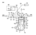
- FIG. 4 is a schematic view for explaining a configuration related to the engine 45.
- An intake port 81 and an exhaust port 82 facing the combustion chamber 56 are formed in the cylinder head 51.
- an ignition plug 80 is disposed in the cylinder head 51 so as to face the combustion chamber 56.
- An ignition coil 79 is connected to the ignition plug 80.
- the ignition coil 79 stores electrical energy for causing the spark plug 80 to spark discharge.
- An intake valve 83 is disposed at the intake port 81, and an exhaust valve 84 is disposed at the exhaust port 82.
- the intake valve 83 opens and closes the intake port 81, and the exhaust valve 84 opens and closes the exhaust port 82.
- the intake valve 83 and the exhaust valve 84 are driven by a valve gear (not shown) interlocked with the crankshaft 48.
- the intake port 81 is connected to the intake port 85
- the exhaust port 82 is connected to the exhaust port 86.
- the engine 45 is a fuel injection type engine in this embodiment. That is, the injector 87 is disposed at the intake port 85 on the upstream side of the intake valve 83. The injector 87 is arranged to inject fuel toward the intake port 81. Fuel is supplied to the injector 87 from a fuel tank 88 via a fuel hose 89. A fuel pump 90 is disposed in the fuel tank 88. The fuel pump 90 pumps the fuel in the fuel tank 88 to the fuel hose 89.
- a throttle body 91 is disposed upstream of the injector 87 in the intake port 85.
- the throttle body 91 holds a throttle valve 92, an intake pressure sensor 93, an intake temperature sensor 94, and a throttle opening degree sensor 95.
- the throttle valve 92 may be, for example, a butterfly valve including a plate-like valve body rotatably disposed in the intake port 85.
- the throttle valve 92 is mechanically coupled to the accelerator grip 32 via a wire 99 in this embodiment. That is, when the accelerator grip 32 is operated, the throttle valve 92 is displaced (angular displacement in this embodiment) according to the operation direction and the operation amount, and the throttle opening degree is changed. The position of the throttle valve 92 is detected by a throttle opening degree sensor 95.
- the throttle opening sensor 95 detects the throttle opening and also detects the accelerator opening as an accelerator command value. It also functions as an accelerator operation detection unit.
- the accelerator opening degree is an operation amount of the accelerator grip 32.
- the intake pressure sensor 93 detects the pressure of the air taken in.
- the intake air temperature sensor 94 detects the temperature of the air taken in.
- the crankcase 49 is attached with a crank angle sensor SE1 for detecting the rotation angle of the crankshaft 48.
- the crankcase 49 is further provided with a reference angle sensor SE2 that gives a reference angular position of the crankshaft 48 when the engine is started.
- an engine temperature sensor 97 for detecting the temperature of the engine 45 is attached to the cylinder block 50.
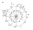
- FIG. 5 and FIG. 6 are schematic diagrams for explaining the configuration of the rotor 75 etc. for detecting the rotational position of the crankshaft 48, that is, the crank angle.
- FIG. 5 is a side view taken along the rotation axis C of the crankshaft 48
- FIG. 6 is a schematic view in which the outer peripheral surface of the rotor 75 is developed in a band shape.
- a rotor 75 which is a rotating member for detecting a crank angle, is fixed to the crankshaft 48.
- the rotor 75 rotates around a common rotation axis C with the crankshaft 48.
- the crankshaft 48 and the rotor 75 rotate in the rotational direction R1.
- Rotor 75 may be shared with rotor 58 for generator 44, as shown in FIG.
- a crank angle sensor SE1 is disposed to face the rotor 75, and a crank angle detection unit is configured by the rotor 75 and the crank angle sensor SE1.
- the crank angle sensor SE1 is, for example, an electromagnetic pickup or an optical pickup, and is a first detection unit that outputs an electric signal in response to an object passing through the first detection area SR1.
- a reference angle sensor SE2 for detecting a reference crank angle for ignition control when the engine 45 is started is disposed to face the rotor 75.
- the reference angle sensor SE2 may have the same configuration as the crank angle sensor SE1.
- the reference angle sensor SE2 is configured of an electromagnetic pickup or an optical pickup and is an electric signal responsive to an object passing through the second detection area SR2. Is a second detection unit that outputs
- the first detection area SR1 and the second detection area SR2 are arranged at different positions. Accordingly, the crank angle sensor SE1 and the reference angle sensor SE2 are disposed at different positions. More specifically, the first and second detection areas SR1 and SR2 are disposed at different positions with respect to the rotational direction R1 of the rotor 75, and are also disposed at different positions with respect to the direction along the rotation axis C of the rotor 75. ing. Accordingly, the crank angle sensor SE1 and the reference angle sensor SE2 are disposed at different positions with respect to the rotational direction R1 of the rotor 75, and also at different positions with respect to the direction along the rotation axis C of the rotor 75.
- the rotor 75 has a circular outer circumferential surface 75 a in a side view as viewed in the direction of the rotation axis C of the crankshaft 48. That is, the outer circumferential surface 75 a forms a cylindrical surface along the rotational direction R 1 of the crankshaft 48, that is, an endless belt-like surface. A configuration in which this endless belt-like surface is developed into a plane is shown in FIG.
- first detection bodies P1, P2,..., P11 are arranged at equal intervals along the circumferential direction, that is, along the rotational direction R1 of the crankshaft 48.
- the first detection bodies P1, P2,..., P11 are flat protrusions (detection teeth) projecting outward from the outer peripheral surface 75a by a fixed height outward in the rotation radius.
- the crank angle sensor SE1 is disposed so that the outer surface 75a of the rotor 75 and the trajectories through which the first detection bodies P1, P2,..., P11 pass cross the first detection area SR1.
- the crank angle sensor SE1 outputs a detection signal that fluctuates each time the first detection bodies P1, P2,..., P11 pass as the rotor 75 rotates.
- Each of the first detection bodies P1, P2, ..., P11 has a front end located downstream with respect to the rotational direction R1 and a rear end located upstream with respect to the rotational direction R1.
- the output signal of the crank angle sensor SE1 fluctuates according to the passage of the front end and the passage of the rear end of each detector.
- the rear end of each of the first detection bodies P1, P2, ..., P11 is used as a detection edge. That is, from the output signal of the crank angle sensor SE1, a signal corresponding to the rear end of the first detection object P1, P2, ..., P11 is extracted as a significant signal to generate a crank pulse. Therefore, the plurality of first detection bodies P1, P2,..., P11 are arranged on the outer peripheral surface 75a of the rotor 75 so that the respective rear ends are equally spaced.
- each first rear end is aligned with 11 of the 12 positions obtained by equally dividing the full angular range of 360 degrees around the crankshaft 48 into 12 by 30 degrees, and 11 first detection bodies P1,1 are obtained.
- P2, ..., P11 are arranged.
- the eleven first detection bodies P1 to P11 have the same circumferential length of the rotor 75, and as a result, their front ends are also equally spaced along the circumferential direction of the rotor 75.
- One position where the first detection objects P1, P2, ..., P11 are missing is a missing tooth position N. Since the distance between the first detection bodies P1 and P11 before and after the missing tooth position N is long, the interval between crank pulses becomes long.
- the reference position of the crankshaft 48 can be determined, and from the reference position, a crank pulse generated along with the passage of the first detection bodies P1, P2, ..., P11.
- the rotational position (crank angle) of the crankshaft 48 can be determined by counting.
- the missing tooth position N is a reference position detection unit that gives a reference position of the crank angle.
- the missing tooth position N is, for example, located at a position where it enters the first detection area SR1 in the vicinity of the bottom dead center position (a range including the bottom dead center position) which is a crank angle where the piston 54 approaches the crankshaft 48 most. There is. Further, the missing tooth position N is arranged to pass through the first detection area SR1 in the expansion stroke or intake stroke of the engine 45 and be detected by the crank angle sensor SE1. Then, for example, the sixth first detection body P6 counted from the missing tooth position N is an energization start detection body which gives the energization start timing to the ignition coil 79, and the seventh first detection body P7 next to it is , And an ignition detector that provides ignition timing for causing spark discharge with the spark plug 80.
- the ignition detector P7 is arranged, for example, to face the crank angle sensor SE1 immediately before the top dead center position where the piston 54 is the crank angle at which the piston 54 is most separated from the crank shaft 48. That is, the ignition detection body P7 is the first detection body closest to the top dead center position on the downstream side of the rotation direction R1 of the top dead center position among the plurality of first detection bodies P1 to P11.
- the second detection body S is disposed on the outer circumferential surface 75a of the rotor 75 at a position shifted in the direction of the rotation axis C with respect to the first detection bodies P1 to P11. .
- the second detection body S has the same position as one of the plurality of first detection bodies P1 to P11 (the first detection body P9 in FIGS. 5 and 6) with respect to the rotational direction R1 of the rotor 75.
- the second detection body S is integrally formed with one first detection body P9. That is, one of the protrusions constituting the plurality of first detection bodies P1 to P11 (protrusions corresponding to the first detection bodies P9) extends long in the rotation axis C direction.
- a part of the elongated projection constitutes the first detection body P9, and the other part constitutes the second detection body S.
- the outer peripheral surface 75a of the rotor 75 is equally divided into two regions by the widthwise center line 76 in the direction of the rotation axis C, the row of first detection bodies P1 to P11 is disposed in one of the regions, the other region The second detection body S is disposed on the Thus, the first detection bodies P1 to P11 and the second detection bodies S are arranged at different positions with respect to the rotation axis C direction.
- the second detection body S and the second detection area SR2 are arranged such that the second detection body S enters the second detection area SR2 immediately before the energization start detection body P6 enters the first detection area SR1.
- the relative arrangement of In this embodiment the second detection body S has a detection edge at the rear end. Then, immediately before the rear end of the energization start detector P6 is detected by the crank angle sensor SE1, the rear end of the second detector S is detected by the reference angle sensor SE2.
- the reference angle sensor SE2 detects the rear end of the second detection body S. Therefore, the reference angle sensor SE2 detects the second detection body S in the compression stroke of the engine 45.
- the long projections constituting the first detection body P9 and the second detection body S have the length in the direction along the rotation axis C longer than the other first detection bodies P1 to P8, P10 and P11, and the other long projections It has the same configuration as that of the first detection objects P1 to P8, P10, and P11.
- the arrangement of the second detection body S is not limited to the arrangement example shown in FIG. 5 and FIG. 6, but the rotation axis is in the same position as any of the first detection bodies P1 to P11 in the rotational direction R1. It may be arranged to be shifted from the first detection objects P1 to P11 in the C direction.
- the arrangement of the reference angle sensor SE2 may be used as a reference. Specifically, when the arrangement of the reference angle sensor SE2 is determined in search of a space where the reference angle sensor SE2 can be arranged around the rotor 75, the second detection area SR2 is determined.
- the first detection body which is to align with the second detection area SR2 in the direction of the rotation axis C immediately before being detected by the crank angle sensor SE1 by the energization start detection body P6 entering the first detection area SR1 is specified .
- the second detection body S may be disposed at the same position in the direction of the rotation axis C and the specified first detection body.
- the second detection body S is detected by the reference angle sensor SE2 immediately before the detection of the energization start detection body P6 by the crank angle sensor SE1. That is, after the second detection body S is detected by the reference angle sensor SE2, the energization start detection body P6 is detected by the crank angle sensor SE earlier than any other first detection body.
- the rotational load of the engine 45 is most increased immediately before the compression top dead center. Therefore, the angular position of the crankshaft 48 when the engine 45 stops often comes before compression top dead center. More specifically, the load when the first detection body P7 (ignition detection body) immediately before the compression top dead center is opposed to the crank angle sensor SE1 is the largest, and 90 degrees with respect to the angular position at that time. In many cases, the engine 45 is stopped at an angular position about a degree ago. That is, as shown in FIG. 5, when the engine 45 is stopped, the range from the fourth first detection body P4 to the fifth first detection body P5 counted from the missing tooth position N is the crank angle The probability of being located in the first detection area SR1 of the sensor SE1 is high.
- the second detection body S When cranking is started from the state shown in FIG. 5, the second detection body S promptly enters the second detection area SR2 in the first compression stroke, and immediately thereafter, the energization start detection body P6 is the first detection area Enter SR1. Therefore, if the discrimination of the first detection bodies P1 to P11 is started on the basis of the timing at which the reference angle sensor SE2 detects the rear end edge of the second detection body S, the energization start detection is performed in the first compression stroke after the cranking start.
- the body P6 can be determined immediately, and energization of the ignition coil 79 can be started. Thus, ignition control can be started immediately after the start of cranking.
- the engine 45 can be started quickly without waiting for the detection of the missing tooth position N. Specifically, the engine 45 can be started by igniting when the crankshaft 48 first passes over the compression top dead center after the start of cranking. Thereby, the engine start in the first compression stroke can be reliably performed.
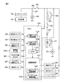
- FIG. 7 is a block diagram for illustrating an electrical configuration related to control of engine 45.
- the outputs of the sensors 93 to 95, 97, SE1, and SE2 are input to an ECU (Electronic Control Unit) 100.
- Other sensors such as a vehicle speed sensor 98 may be connected to the ECU 100 as necessary.
- the vehicle speed sensor 98 is a sensor that detects the vehicle speed of the motorcycle 1 and may be a wheel speed sensor that detects the rotational speed of the wheels 3 and 4.
- the ECU 100 has an interface circuit for capturing signals output from the sensors 93 to 95, 97, 98, SE1, and SE2.
- the interface circuit includes a one-side edge detection circuit 106 which is a crank pulse generation unit that shapes the output signal of the crank angle sensor SE1 to generate a crank pulse.
- the one-side edge detection circuit 106 detects a signal corresponding to the rear end of the first detection body P1 to P11 from the output signal of the crank angle sensor SE1 and generates a crank pulse.
- the interface circuit includes a one-side edge detection circuit 107 that performs waveform shaping on the output signal of the reference angle sensor SE2 to generate a reference angle pulse.
- the one-side edge detection circuit 107 detects a signal corresponding to the rear end of the second detection body S from the output signal of the reference angle sensor SE2, and generates a reference angle pulse.
- the ECU 100 includes a CPU 110.
- the CPU 110 drives the fuel pump 90 and the injector 87 based on output signals from the sensors 93 to 95, 97, SE1, SE2, etc., thereby controlling the fuel injection amount and the fuel injection timing.
- an ignition coil 79 is connected to the ECU 100.
- the ignition coil 79 stores electric power for causing spark discharge of the spark plug 80 (see FIG. 4).
- the CPU 110 controls energization of the ignition coil 79 based on output signals of the sensors 93 to 95, 97, SE1, SE2, etc., thereby controlling the ignition timing (discharge timing of the ignition plug 80).
- the CPU 110 controls the energization of the starter motor 43, thereby controlling the start of the engine 45.
- the battery 25 is connected to the feed line 26 via the fuse 27.
- the power stored in the battery 25 is supplied to the starter motor 43, the ECU 100, the ignition coil 79, the injector 87, the fuel pump 90, and the like through the feed line 26. Further, the battery 25 is supplied with the power generated by the generator 44 and rectified and regulated by the regulator 78. Thereby, the battery 25 is charged while the engine 45 is in operation.
- a main switch 40 is interposed in the feed line 26.
- a parallel circuit of brake switches 135 and 136 is connected to the feed line 26 on the opposite side of the main switch 40 from the battery 25.
- the brake switch 135 is a switch that conducts when the rear wheel brake lever 38 is operated and is disconnected when the rear wheel brake lever 38 is not operated.
- the brake switch 136 is a switch which is turned on when the front wheel brake lever 39 is operated and is turned off when the front wheel brake lever 39 is not operated.
- a starter button 35 is connected in series to the parallel circuit of the brake switches 135 and 136, a diode 137 is connected in series to the starter button 35, and a coil of the relay 77 is connected to the diode 137. ing.
- the starter motor 43 is connected to the feed line 26 via the relay 77. Therefore, when the starter button 35 is turned on in a state in which the rear wheel brake lever 38 or the front wheel brake lever 39 is operated, the relay 77 conducts, and the power of the battery 25 is supplied to the starter motor 43.
- the ECU 100, the ignition coil 79, the injector 87, the fuel pump 90, and the like are connected to the main switch 40 on the opposite side to the battery 25. That is, when the main switch 40 conducts, power is supplied to the ECU 100, and the control operation by the ECU 100 is started.
- the ECU 100 includes a drive control unit 101 for driving actuators such as an ignition coil 79, an injector 87, a fuel pump 90, and a relay 77.
- the drive control unit 101 includes a plurality of drive circuits for energizing the actuators.
- the plurality of drive circuits include an ignition coil drive circuit 103 for energizing the ignition coil 79 and an injector drive circuit 104 for driving the injector 87.
- the CPU 110 controls energization of the actuators by controlling their drive circuits.
- the drive control unit 101 of the ECU 100 is connected between the diode 137 and the coil of the relay 77. Therefore, even when the starter button 35 is off, the ECU 100 can drive the relay 77 to operate the starter motor 43.
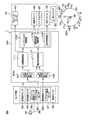
- FIG. 8 is a block diagram for explaining a functional configuration of ECU 100.
- the ECU 100 and the sensors 93 to 95, 97, SE1, SE2 constitute an engine control device for controlling the engine 45. And an engine system is constituted including this engine control device and engine 45.
- the ECU 100 incorporates the CPU 110. When the CPU 110 executes a program, each function of the function processing unit described below is realized.
- the ECU 100 includes a start control unit 111, an engine output control unit 112, and a detected body determination unit 113 as a function processing unit.
- the engine output control unit 112 controls the output of the engine 45.
- engine output control unit 112 includes a fuel supply control unit 115 and an ignition control unit 116.
- the fuel supply control unit 115 controls the fuel pump 90 and the injector 87 to control the fuel injection amount and the fuel injection timing.
- the ignition control unit 116 controls the spark discharge timing (ignition timing) of the spark plug 80 by controlling energization of the ignition coil 79.
- the output of the engine 45 can be controlled by controlling one or both of the fuel injection amount and the ignition timing. In addition, if the fuel injection amount is zero and fuel cut is performed, the engine 45 can be stopped.
- the start control unit 111 determines that cranking is being performed, and performs control for starting the engine. That is, the start control unit 111 instructs the engine output control unit 112 to execute fuel supply control and ignition control. Thus, the fuel is injected from the injector 87 in synchronization with the rotation of the crankshaft 48, and the energization control of the ignition coil 79 is performed to start the engine 45.
- the CPU 110 may further include an idle stop control unit as a function processing unit. That is, the CPU 110 may stop the engine 45 and shift to the idle stop state if the idle stop condition is satisfied while the engine 45 is in the idle state.
- the idle state is a state in which the throttle opening is fully closed and the engine rotational speed is a value within an idle rotational speed range (for example, 2500 rpm or less).
- the idle stop state refers to a state in which the operation of the engine 45 is automatically stopped under the control of the CPU 110. Specifically, the CPU 110 stops the fuel supply to the engine 45 by giving a fuel cut command to the engine output control unit 112, thereby stopping the engine 45.
- the CPU 110 may further include, as a function processing unit, an engine restart control unit that restarts the engine 45 when a predetermined operation of the accelerator grip 32 is detected while the engine 45 is in the idle stop state.
- Restarting means that the engine 45 in the idle stop state is started.
- the CPU 110 operates the starter motor 43 by controlling the drive control unit 101 to cause the relay 77 (see FIG. 7) to conduct, and performs fuel supply control and ignition to the engine output control unit 112. Give control command. Thereby, the starter motor 43 is operated, fuel is injected from the injector 87, spark discharge of the ignition coil 79 is performed, and the engine 45 is restarted.
- the detection body determination unit 113 is a detection body determination unit that determines the detection bodies P1 to P11 detected by the crank angle sensor SE1.
- the detection body determination unit 113 detects the crank pulse generated by the one-side edge detection circuit 106 (see FIG. 7) based on the output signal of the crank angle sensor SE1 and the one-side edge detection circuit 107 based on the output signal of the reference angle sensor SE2.
- the detection object identification unit 113 uses the reference angular pulse generated by Specifically, based on the crank pulse and the reference angular pulse generated in response to the passage of the rear end of the detection objects P1 to P11, S, the detection object identification unit 113 detects the missing tooth position N or the second detection object. S is detected as a reference position.
- the detection body determination unit 113 determines the plurality of first detection bodies P1 to P11 including the energization start detection body P6 and the ignition detection body P7 by counting the crank pulses from the reference position. The determination result is provided to the fuel supply control unit 115 and the ignition control unit 116.
- the ignition control unit 116 starts energization of the ignition coil 79 when the energization start detector P6 or the second detector S is detected. Further, when the ignition detection body P7 is detected, the ignition control unit 116 shuts off the energization to the ignition coil 79. Thereby, the energy stored in the ignition coil 79 is supplied to the spark plug 80, and the spark plug 80 causes spark discharge in the combustion chamber 56.
- FIG. 9 is a flowchart for explaining the details of the engine start control.
- the CPU 110 executes interrupt processing each time a crank pulse or a reference angle pulse is input. First, the CPU 110 determines whether or not the missing tooth position N has already been detected (step S1). If the missing tooth position N has been detected (step S1: YES), the CPU 110 determines whether the crank pulse corresponds to the energization start detection object P6 (step S3). That is, it is determined whether or not the detected body detected by the crank angle sensor SE1 is the energization start detected body P6.
- step S3 If it is the energization start detector P6 (step S3: YES), the CPU 110 starts energization to the ignition coil 79 (step S4), otherwise (step S3: NO), the CPU 110 energizes the ignition coil 79 (Step S5). That is, the CPU 110 maintains the shutoff state if the energization of the ignition coil 79 is already in the cutoff state, and shuts off the energization when the ignition coil 79 is being energized. By interrupting from the energized state, the energy stored in the ignition coil 79 is supplied to the spark plug 80, and spark discharge occurs in the spark plug 80. Thereafter, other interrupt processing is further executed (step S6).
- the other interrupt processing includes the determination of the first detection bodies P1 to P5 and P7 to P11 corresponding to the crank pulse that has caused the interrupt, the detection of the missing tooth position N, the fuel injection control and the like.
- the second detection body S may be determined earlier than the missing tooth position N (step S2).
- the detection of the energization start detection body P6 is performed with the position of the second detection body S as a reference position (step S3). Therefore, it is possible to control energization of the ignition coil 79 without waiting for detection of the missing tooth position N. That is, when the engine is started, the energization control to the ignition coil 79 and the determination of the first detection bodies P1 to P11 are performed based on which one of the missing tooth position N and the second detection body S is detected earlier. .
- step S1 YES
- the interrupt processing in response to the reference angular pulse corresponding to the second detection body S is omitted thereafter. Therefore, when the missing tooth position N is detected earlier than the second detection body S at engine startup, ignition control, fuel injection control, and other interrupt processing are executed solely on the basis of the missing tooth position N.
- the second detection body S is arranged to be detected immediately before the energization start detection body P6. That is, the first detection body detected first after the second detection body S is detected is the energization start detection body P6. Therefore, at the time of engine startup, the second detection body S can reliably provide the reference position before the energization start detection body P6 first passes through the detection region SR1 of the crank angle sensor SE1. That is, when the energization start detection object P6 is detected by the crank angle sensor SE1 first, energization of the ignition coil 79 can be reliably started. Thus, ignition control can be started promptly at the time of engine start.
- the second detection body S is arranged to be detected by the reference angle sensor SE2 in the vicinity of the top dead center position (a predetermined range before the top dead center position), and the missing tooth position N is the bottom dead center
- the crank angle sensor SE1 is disposed so as to be detected near the position (a predetermined range so as to include the bottom dead center position). That is, the rotation of the crankshaft 48 is more stable when the missing tooth position N is detected by the crank angle sensor SE1 than when the second detection body S is detected by the reference angle sensor SE2. Therefore, after start-up of engine 45 is completed, determination of each of the first detection bodies P1 to P11 can be made more accurately by using the missing tooth position N as a reference position, so the control of the engine 45 can be made more accurately. It can do.
- FIG. 10 is a waveform diagram showing an example of waveforms of a crank pulse, a reference angle pulse and an ignition signal at the time of engine start.
- the main switch 40 is turned on at time t1, and the starter button 35 is operated at time t2.
- the rotation of the crankshaft 48 is started, and a crank pulse is generated in response to the passage of the detection bodies P1 to P11.
- a crank pulse corresponding to the rear end of the third first detection body P3 counted from the missing tooth position N first occurs.
- a reference angular pulse corresponding to the rear end of the second detection body S is generated.
- a crank pulse corresponding to the rear end of the energization start detector P6 is generated.
- the CPU 110 When the second detection body S is detected, the CPU 110 thereafter starts energizing the ignition coil 79 at time t3 in synchronization with the crank pulse corresponding to the energization start detection body P6. Then, in synchronization with the crank pulse corresponding to the ignition detector P7 detected next to the energization start detector P6, the CPU 110 stops the energization of the ignition coil 79 at time t4.
- crank pulses corresponding to the first detection objects P8 to P11 are generated, and the CPU 110 executes necessary processing at each angular position.
- the CPU 110 detects the missing tooth position N by monitoring the time interval of the crank pulse.
- crank pulses corresponding to the first detection bodies P1 to P11 are counted with the missing tooth position N as a reference position, and necessary processing is executed at angular positions corresponding to the first detection bodies P1 to P11.
- the energization start detection object P6 is determined only after the crankshaft 48 rotates approximately once, and ignition control is started. Therefore, the time until the engine 45 starts up becomes longer.
- the ignition control can be started by determining the energization start detection body P6 before the crankshaft 48 makes one rotation. Can improve the startability of the
- the rotor 75 is provided with the plurality of first detection bodies P1 to P11 and the second detection body S.
- the plurality of first detection bodies P1 to P11 are arranged at equal intervals along the rotational direction R1 of the rotor 75.
- the second detection body S is disposed at a position different from the first detection bodies P1 to P11 in the direction along the rotation axis C of the rotor 75. That is, the second detection body S is provided on the rotor 75 at a position shifted from the first detection bodies P1 to P11 along the rotation axis C of the rotor 75.
- the plurality of first detection bodies P1 to P11 pass detection regions SR1 of the crank angle sensor SE1 one after another, and crank pulses are generated accordingly.
- the second detection body S passes through the detection region SR2 of the reference angle sensor SE2 in the compression stroke of the engine 45, whereby a reference angle pulse is generated.
- the first detection bodies P1 to P11 are determined with reference to the reference angular pulse, and in response to the detection of the energization start detection body P6, energization of the ignition coil 79 is promptly started.
- the reliability of the engine start in the first compression stroke can be improved.
- the plurality of first detection bodies P1 to P11 can be determined using the output signal of the reference angle sensor SE2, control of the engine 45 thereafter can also be started promptly.
- the second detection body S is arranged to be displaced from the first detection bodies P1 to P11 along the direction of the rotation axis C, and the reference angle sensor SE2 for detecting the second detection body S It is provided separately from the crank angle sensor SE1 for detecting one of the detection objects P1 to P11.
- the reference angle sensor SE2 may detect the second detection body S immediately before the crank angle sensor SE1 detects the energization start detection body P6, the arrangement of the reference angle sensor SE2 may be freely determined around the rotor 75. Can. Therefore, the degree of freedom in the arrangement of the reference angle sensor SE2 is high, and the space having a margin around the rotor 75 can be selected to arrange the reference angle sensor SE2.
- the second detection body S is formed at the same position as one first detection body with respect to the rotational direction R1 of the rotor 75. More specifically, the second detection body S is integrated with one first detection body, and forms one long protrusion extending in the direction along the rotation axis C. As a result, even when the crank angle sensor SE1 responds to the second detection body S simultaneously (that is, simultaneously detects the second detection S) when the crank angle sensor SE1 detects the first detection body, the crank angle sensor SE1 There is no significant effect on the output signal. In addition, since the first detection bodies P1 to P11 and the second detection bodies S may be disposed close to each other, the size of the rotor 75 in the rotation axis C direction can be reduced.
- the engine system can be miniaturized.
- the erroneous detection can be reduced and the engine 45 can be stably controlled, and the rotor 75 can be further miniaturized.
- the manufacturing process when arranging the first detection bodies P1 to P11, since the second detection bodies S can be arranged simultaneously, the number of manufacturing steps can be reduced. Specifically, when the detection bodies P1 to P11 are sequentially formed by pressing into a cylindrical body, the second detection body S can be formed in the same process as the formation of one first detection body.
- crank angle sensor SE1 and the reference angle sensor SE2 are disposed at different positions with respect to the direction along the rotation axis C.
- the detection areas SR1 and SR2 of the sensors SE1 and SE2 can be easily shifted in the direction of the rotation axis C, so that erroneous detection can be reduced and the arrangement of the sensors SE1 and SE2 can be facilitated.
- the detection regions SR1 and SR2 of the sensors SE1 and SE2 are disposed at different positions in the circumferential direction of the rotor 75.
- the sensors SE1 and SE2 can be easily disposed at different positions in the circumferential direction, so that, for example, a design for downsizing the engine system is facilitated.
- the first detection bodies P1 to P11 and the second detection body S are distributed to both sides of the widthwise center line 76 of the cylindrical portion of the rotor 75.
- the width of the cylindrical portion can be reduced.
- the rotor 75 can be miniaturized, and as a result, the engine system can be miniaturized.
- the arrangement of the second detection body S and the detection area SR2 is set such that the second detection body S is detected by the reference angle sensor SE2 immediately before the top dead center position.
- the reference position is set based on which of the second detection body S and the missing tooth position N is detected earlier, and the energization start detection body P6 and the ignition detection body P7 based on the reference position. Is determined. Therefore, after the starter motor 43 is started, it is possible to quickly determine the energization start detector P6, that is, before the crankshaft 48 makes one rotation. Therefore, ignition control can be started promptly after the starter motor 43 is started, and the engine 45 can be started promptly.
- the second detection body S is detected by the reference angle sensor SE2 immediately before the conduction start detection body P6 is detected by the crank angle sensor SE1. P6 can be determined promptly and reliably. Thereby, the engine 45 can be started promptly.
- the energization start detector P6 and the ignition detector P7 are determined based on the missing tooth position N without using the second detector S as a reference. That is, in this embodiment, although the second detection body S is used with priority given to starting ignition control early at the time of engine start, after the engine start is completed, not the second detection body S but the missing tooth position N
- the first detection objects P1 to P11 are determined as a reference. Since the missing tooth position N is disposed near the bottom dead center position and detected in the expansion stroke or intake stroke of the engine 45, the rotation of the crank shaft 48 at the time of detection is stable. As a result, after completion of the engine start, the determination accuracy of the first detection bodies P1 to P11 can be further enhanced, and accurate and efficient engine control can be realized.
- step S1 may be omitted in the flowchart of FIG. Even in this case, ignition control at the time of engine start can be started early, and subsequent engine control can be performed without any problem.
- the first detection bodies P1 to P11 and the second detection body S are configured by the projections provided on the outer peripheral surface 75a of the rotor 75.
- these detection bodies may be concave portions formed in the outer peripheral surface 75a, or may be magnetic members embedded in the outer peripheral surface 75a.
- the reference position detection unit is configured by the missing tooth position N, but the reference position detection unit may be configured by a protrusion or a recess or a magnetic body.
- the front ends of the first detection bodies P1 to P11 are arranged at equal intervals
- the front ends of P1 to P11 and S may be used as detection edges.
- the output signal of the crank angle sensor SE1 is stable, and accordingly, stable detection is possible.
- the first detection body detected immediately after the detection of the second detection body S is the energization start detection body P6 at the time of engine startup, and responds to (is synchronized with) the determination.
- energization of the ignition coil 79 is started.
- the arrangement of the second detection body S and the reference angle sensor SE2 is arranged so that the detection of the second detection body S and the detection of the energization start detection body P6 are simultaneously performed.
- the energization of the ignition coil 79 may be started in response to (in synchronization with) the detection.
- the reference position may be given by the second detection body S, and the first detection body may be determined from the ignition detection body P7.
- the second detection body S is a protrusion separated from the first detection bodies P1 to P11. Or the like. Furthermore, the first detection bodies P1 to P11 and the second detection body S do not have to have the same length in the circumferential direction of the rotor 75. Further, the second detection body S may be different in circumferential position of the rotor 75 from any of the first detection bodies P1 to P11.
- the centrifugal clutch 47 is used to connect / disconnect the power transmission path between the engine 45 and the drive wheel (rear wheel 4), but the clutch for connecting / disconnecting the power transmission path is It may be another form such as a hydraulic clutch, an electromagnetic clutch or the like.
- the ECU 100 controls a hydraulic clutch, an electromagnetic clutch or the like according to the engine rotation speed, the same operation as in the case of using the centrifugal clutch 47 can be realized.
- the throttle valve 92 mechanically interlocked with the accelerator grip 32 by the wire 99 has been described.
- a so-called electronic throttle device may be applied. That is, while the throttle valve 92 is driven by a throttle actuator such as an electric motor, an accelerator opening sensor may be provided which detects an operation amount (accelerator opening) of the accelerator grip 32. In this case, the output signal of the accelerator opening sensor is input to the ECU 100. The ECU 100 drives the throttle actuator according to the output signal of the accelerator opening sensor to adjust the throttle opening.
- scooter type motorcycle 1 was mentioned as an example in the above-mentioned embodiment, the present invention can be applied to other types of motorcycles such as a moped type and a sports type. Furthermore, the present invention can be applied not only to motorcycles but also to straddle type vehicles such as all-terrain vehicles and snowmobiles. Furthermore, the present invention can be applied not only to straddle type vehicles, but also to engines for other types of vehicles and engines for applications other than vehicles such as generators.
Landscapes
- Engineering & Computer Science (AREA)
- Physics & Mathematics (AREA)
- Chemical & Material Sciences (AREA)
- Combustion & Propulsion (AREA)
- Mechanical Engineering (AREA)
- General Engineering & Computer Science (AREA)
- General Physics & Mathematics (AREA)
- Electromagnetism (AREA)
- Theoretical Computer Science (AREA)
- Signal Processing (AREA)
- Combined Controls Of Internal Combustion Engines (AREA)
Abstract
クランク軸を有するエンジンと、クランク軸とともに回転軸線まわりに回転する回転部材と、回転部材に設けられた複数の第1検出体と、同じく回転部材に設けられた第2検出体と、第1および第2検出体をそれぞれ検出する第1および第2検出手段と、点火制御手段とを含むエンジンシステムが提供される。複数の第1検出体は、回転部材の回転方向に沿って等間隔に配置されている。第2検出体は、前記回転軸線に沿う方向において第1検出体とは異なる位置に配置されている。第1検出手段は、回転部材の回転に伴って第1検出体が通過する軌道上の固定位置に第1検出領域を有する。第2検出手段は、回転部材の回転に伴って第2検出体が通過する軌道上の固定位置に第2検出領域を有し、エンジンの圧縮行程において第2検出体を検出する。点火制御手段は、第2検出手段によって第2検出体が検出されたことに応答して点火コイルへの通電のための通電制御を開始する。
Description
この発明は、燃焼室内で点火プラグを火花放電させて燃料を燃焼させるエンジン(内燃機関)を備えたエンジンシステム、および前記エンジンシステムを備えた車両に関する。
燃料噴射式のエンジンは、クランク軸の回転角度を検出するためのクランク角検出装置を備えている。クランク角検出装置は、クランク軸とともに回転するロータと、ロータの回転にともなって検出信号を発生するピックアップとを含む。ロータの外周には、等間隔に検出歯が設けられている。ピックアップが出力する検出信号は、検出歯の通過に伴って変動する。この検出信号を整形することによって、クランクパルスが生成される。従来のクランク角検出装置のなかには、ロータ外周の一箇所に、検出歯を欠落させた欠け歯位置が設けられたものがある。この欠け歯位置ではクランクパルスが発生しないので、欠け歯位置の前後においてクランクパルスの間隔が長くなる。これにより、クランク軸の基準回転位置が得られる。この基準回転位置を基準としてクランクパルスを計数(検出歯を計数)することによって、クランク角を求めることができる。こうして求められたクランク角に基づいて、燃料噴射制御および点火制御が行われる。
特許文献1は、ロータの外周面に、後端位置が等間隔となるように複数の凸部を配置し、その凸部をピックアップで検出してクランクパルスを発生するクランク角検出装置を開示している。複数の凸部のうちの一つは、後端から前端までの長さが他の凸部よりも長くなっており、クランク角の基準角度を示す凸部(以下「基準凸部」という。)とされている。この基準凸部は、ピストンの上死点に対応したクランク角(上死点位置)の直前に配置されている。ピックアップは、複数の凸部の各前端で負パルスを生成し、各凸部の後端で正パルスを生成する。負パルスおよび正パルスはそれぞれ波形整形されて前端位置パルスおよび後端位置パルスとなる。前端位置パルスの発生タイミングでCPUに対する割り込みが発生し、それによって、前端位置パルスの発生間隔が計測される。また、後端位置パルスの発生タイミングでもCPUに対する割り込みが発生し、それによって、後端位置パルスの発生間隔が計測される。基準凸部の前端位置とその直前の凸部の前端位置との間隔は短いので、前端位置パルスの発生間隔と後端位置パルスの発生間隔との比に基づいて、基準凸部の後端位置が検出される。これに同期して、点火コイルへの通電が開始される。そして、基準凸部の次の凸部の後端位置が検出されると、点火コイルへの通電が停止させられ、点火プラグの火花放電を生じさせて、初爆点火が実行される。こうして、クランク軸が1回転するまでに正確なクランク角を検出して、適切な初爆タイミングを与えることができる。
キャブレター式のエンジンでは、クランク角検出のためのロータには、ただ一つの突起が設けられており、その突起の検出に基づいて点火コイルへの通電および点火プラグの火花放電が制御される。したがって、クランキングを開始すると、速やかに点火制御を開始できるから、始動性がよい。
それに対して、燃料噴射式のエンジンでは、前述のように、複数の凸部がロータの周囲に配置されており、それぞれに機能を持たせているので、それらの凸部がどの機能の凸部であるのかが判別される以前の期間には、点火制御を開始することができない。より具体的には、たとえば他の凸部と異なる形状の凸部や欠け歯などから基準となる信号が出力される構成が備えられる。その基準となる信号に基づいて凸部が判別される。したがって、その基準となる信号が出力されるまで、点火制御を開始できない。ところが、エンジンの停止位置によっては、スタータモータによるクランキングの開始から圧縮上死点を一度乗り越えてから、はじめて基準となる信号が出力される場合がある。したがって、点火制御の開始までに長い時間を要するので、エンジンの始動性が悪い。スタータモータは、最初の圧縮上死点を確実に乗り越えてクランク軸を回転させることができる出力が得られるように、可能な限り小型に設計されていてもよい。
特許文献1の先行技術では、上死点位置の直前に周方向の長さが他の凸部とは異なる基準凸部が配置されている。したがって、この先行技術に係る装置は、適切な初爆タイミングを与えることができる。
しかし、とくにクランキングを開始した直後の最初の圧縮上死点を乗り越えるときに、ロータの回転速度は、圧縮上死点に近づくに従って零に近づく。したがって、ピックアップが出力する信号の時間間隔は、圧縮上死点に近くなるに従って大きくなる。そのため、基準凸部の検出に基づく信号か否かの判別が困難になる。その結果、クランキングを開始した後の最初の圧縮行程でエンジンを確実に始動することができない。
前述の欠け歯等の基準となる信号を発生するための構成は、クランク軸の回転速度が安定するクランク角でピックアップに検出されるように配置されるのが通常である。この構成であれば、特許文献1の先行技術における前述の課題は生じない。しかし、エンジンの停止位置は、圧縮行程の前であることが多いから、欠け歯等の通常配置では、クランキングを開始した直後の最初の圧縮上死点を超えた後でなければ基準となる信号を生成できないことが多い。
このように、これまで提案されてきた燃料噴射式のエンジンでは、クランク軸の基準位置を確実に検出し、かつクランキング開始後の最初の圧縮行程で点火してエンジンを始動することは難しかった。
そこで、この発明の目的は、クランキング開始後の最初の圧縮行程でエンジンを点火し、始動性を改善できるエンジンシステムを提供することである。
この発明の一実施形態は、クランク軸を有するエンジンと、クランク軸とともに回転軸線まわりに回転する回転部材と、回転部材に設けられた複数の第1検出体と、同じく回転部材に設けられた第2検出体と、第1および第2検出体をそれぞれ検出する第1および第2検出手段と、点火制御手段とを含むエンジンシステムを提供する。前記エンジンは、燃焼室内で火花放電する点火プラグと、前記点火プラグに供給するためのエネルギーを蓄える点火コイルと、クランク軸とを有する。前記複数の第1検出体は、前記回転部材の回転方向に沿って等間隔に配置されている。前記第2検出体は、前記回転軸線に沿う方向において前記第1検出体とは異なる位置に配置されている。前記第1検出手段は、前記回転部材の回転に伴って前記第1検出体が通過する軌道上の固定位置に第1検出領域を有し、前記第1検出体の前記第1検出領域の通過に伴って変動する検出信号を出力する。前記第2検出手段は、前記回転部材の回転に伴って前記第2検出体が通過する軌道上の固定位置に第2検出領域を有し、前記第2検出体の前記第2検出領域の通過に伴って変動する検出信号を出力し、前記エンジンの圧縮行程において前記第2検出体を検出する。前記点火制御手段は、前記第2検出手段によって前記第2検出体が検出されたことに応答して前記点火コイルへの通電のための通電制御を開始する。「通電制御」とは、点火コイルへの通電のための制御を意味する。通電制御は、点火コイルへの通電のほか、点火コイルへの通電開始タイミングの検出または判定を含む。一つの実施形態では、通電制御の開始は、通電開始タイミング判定のための制御の開始である。また、他の実施形態では、通電制御の開始は、点火コイルへの通電の開始である。
上記の構成によれば、回転部材には、複数の第1検出体と、第2検出体とが設けられている。複数の第1検出体は回転部材の回転方向に沿って等間隔に配置されている。第2検出体は、回転部材の回転軸線に沿う方向に関して、第1検出体とは異なる位置に配置されている。すなわち、第2検出体は、回転部材の回転軸線に沿って、第1検出体からずらされた配置で回転部材に設けられている。回転部材が回転すると、複数の第1検出体は、第1検出手段の第1検出領域を次々と通過する。これにより、第1検出手段の出力信号を用いてクランクパルスを生成することができる。一方、回転部材が回転すると、第2検出体は、エンジンの圧縮行程において、第2検出手段の第2検出領域を通過する。この第2検出手段の出力信号に応答して、点火コイルへの通電のための通電制御が開始される。したがって、エンジンのクランキングが開始された後の最初の圧縮行程において、点火コイルへの通電制御を開始できる。これにより、最初の圧縮行程でのエンジン始動性を向上できる。また、第2検出手段の出力信号を用いて複数の第1検出体を判別できるので、その後のエンジンの制御も速やかに開始できる。しかも、第2検出体は、第1検出体とは回転軸線方向に沿ってずれて配置されており、その第2検出体を検出するための第2検出手段が、第1検出体を検出するための第1検出手段とは別に設けられている。そのため、回転部材の回転が高速であるか低速であるかにかかわりなく、誤検出が生じ難いから、最初の圧縮行程での始動の確実性と安定したエンジン制御とを確保できる。こうして、最初の圧縮行程で確実にエンジンを点火し、始動性を改善できるエンジンシステムを提供できる。
点火コイルへの通電タイミングは、クランク軸の回転位置によって規定される。したがって、クランク軸の回転位置が点火コイルへの通電を開始すべき位置であるときまたはその直前に、第2検出体が第2検出手段に検出されることが好ましい。つまり、この条件を満たすように、第2検出手段の第2検出領域と第2検出体との相対位置を定められることが好ましい。そこで、たとえば、第2検出手段の配置を定め、その配置に応じて第2検出体の回転部材上における配置を定めることができる。したがって、第2検出手段の配置の自由度が高く、第2検出手段を配置するための設計条件が緩やかである。よって、たとえば、回転部材の周囲の余裕のあるスペースを選んで第2検出手段を配置できる。
この発明の一実施形態では、前記複数の第1検出体が、前記点火プラグの点火タイミングを与える点火検出体を含み、前記点火制御手段が、前記第1検出手段によって前記点火検出体が検出されたことに応答して前記点火コイルへの通電を停止して前記点火プラグを火花放電させる。この構成によれば、第2検出手段が第2検出体を検出すると点火コイルへの通電制御が開始され、その後、第1検出手段が点火検出体を検出すると、点火コイルへの通電が停止されて、点火プラグが火花放電する。これにより、エンジンの燃焼室内の燃料が着火して爆発する。
第2検出体および第2検出領域の配置は、第1検出手段が点火検出体を検出する直前に第2検出体が第2検出手段によって検出されるように設定されていることが好ましい。たとえば、複数の第1検出体は、通電開始検出体および点火検出体を含んでいてもよい。この場合に、第2検出体および第2検出領域の配置は、第1検出手段が通電開始検出体を検出するタイミングと同時またはその直前に第2検出体が第2検出手段によって検出されるように設定されていることが好ましい。第1検出手段が通電開始検出体を検出するタイミングの直前に第2検出体が第2検出手段に検出される配置の場合、第2検出手段が第2検出体を検出した後、他のいずれの第1検出体よりも早く通電開始検出体が第1検出手段に検出される配置が好ましい。通電開始検出体は、点火検出体の直前に第1検出領域を通過するように回転部材上に配置されていてもよい。換言すれば、通電開始検出体が第1検出領域を通過した後、最初に第1検出領域を通過する第1検出体が点火検出体であってもよい。
たとえば、通電開始検出体が第1検出手段によって検出されるのと同時に、第2検出体が第2検出手段によって検出されるように配置を定め、第2検出体が第2検出手段によって検出されたことに応答(同期)して、点火コイルへの通電を開始してもよい。
また、通電開始検出体が第1検出手段によって検出されるよりも前に第2検出体が第2検出手段によって検出される配置とし、第2検出体の検出を待って第1検出体の判別を開始し、通電開始検出体の検出に応答(同期)して、点火コイルへの通電を開始してもよい。この場合、通電開始検出体の検出タイミングとその直前の第1検出体の検出タイミングとの間のタイミングで、第2検出体が第2検出手段に検出される配置とすることが好ましい。つまり、或る第1検出体が第1検出手段によって検出され、次に別の第1検出体が第1検出手段によって検出されるよりも前に第2検出体が第2検出手段によって検出され、次いで、他のいずれの第1検出体よりも早く通電開始検出体が検出される配置が好ましい。
上記の場合の「通電制御」は、第2検出体の検出に応答(同期)して開始される第1検出体の判別と、通電開始検出体の検出に応答(同期)して開始される点火コイルへの通電とを含む。このような「通電制御」が第2検出体の検出に応答して開始される。
この発明の一実施形態では、前記第2検出体が、前記回転部材の周方向に関して、前記複数の第1検出体のいずれかと同じ位置に配置されている。この構成によれば、第1検出手段が、第1検出体を検出するときに、第2検出体にも同時に応答(すなわち、第2検出体も検出)してしまったとしても、第1検出手段の出力信号に大きな影響が生じない。しかも、第1検出体および第2検出体を接近して配置しても差し支えないので、回転部材の回転軸線方向の大きさを小さくできる。これにより、エンジンシステムを小型化できる。
この発明の一実施形態では、前記第2検出体が、前記複数の第1検出体のいずれかと一体化している。この構成により、誤検出を少なくしてエンジンを安定に制御できるうえに、回転部材をより小型化できる。また、製造工程において、第1検出体を配置するときに、第2検出体を同時に配置できるので、製造工数を少なくすることができる。
この発明の一実施形態では、前記第1検出手段および前記第2検出手段が、前記回転軸線に沿う方向に関して異なる位置に配置されている。この構成により、第1検出領域および第2検出領域を回転軸線方向に容易にずらすことができるので、誤検出を少なくでき、かつ第1および第2検出手段の配置も容易になる。
第1および第2検出手段は、回転部材の回転方向に関して同位置に配置されていてもよく、異なる位置に配置されていてもよい。配置スペースの確保の容易性の観点からは、第1および第2検出手段は、回転部材の回転方向に関して異なる位置に配置されていることが好ましい。前述のとおり、第2検出領域と第2検出体との相対位置が適切に設定されている限りにおいて、第2検出領域は回転部材の周囲に自由に配置できる。したがって、配置が容易なスペースを選択して第2検出手段を配置すればよい。
この発明の一実施形態では、前記第1検出領域および前記第2検出領域が、前記回転部材の周方向に関して異なる位置に配置されている。この構成により、第1および第2検出手段を周方向の異なる位置に容易に配置できるので、たとえば、エンジンシステムの小型化を図る設計が容易になる。
この発明の一実施形態では、前記回転部材が、前記回転軸線に沿う方向に幅を有する筒状部を備えており、前記第1検出体が、前記筒状部の幅方向の中心位置に対して前記回転軸線に沿う一方向にずらして配置されている。この構成により、筒状部の幅を有効に利用して第1検出体および第2検出体を配置できるので、筒状部の幅を小さくできる。それによって、回転部材を小型化でき、その結果、エンジンシステムを小型化できる。
この発明の一実施形態では、前記第2検出体が、前記筒状部の幅方向の中心位置に対して前記回転軸線に沿う他方向にずらして配置されている。この構成により、第1および第2検出体が、筒状部の幅方向中心に対して両側に振り分けられている。それによって、筒状部の幅を小さくできるので、回転部材の小型化を図ることができる。なお、「両側に振り分けられている」とは、それぞれの重心位置が筒状部の幅方向の中心に対して互いに反対側に位置していることを意味している。したがって、第1検出体および第2検出体の少なくとも一方が、筒状部の幅方向中心を跨いで配置されていてもよい。
この発明の一実施形態では、前記第2検出領域が、前記クランク軸の回転位置が上死点位置の直前の回転位置であるときに前記第2検出体が前記第2検出領域を通過するように配置されている。この構成により、エンジン始動時に、クランク軸の回転位置が上死点位置に達するよりも前に点火コイルへの通電を開始して、エンジンを速やかに始動できる。また、クランク軸の回転位置が上死点位置に達するよりも前に、クランク軸の回転位置に関する基準が得られ、それに応じて、第1検出体の判別が可能になる。その結果、エンジンを速やかに始動できる。
クランク軸の回転位置が圧縮上死点位置の直前であるとき、クランク軸を回転させるために必要な負荷(クランキング負荷)は、極大となる。そのため、エンジンを停止すると、高い確率で、圧縮上死点の前の回転位置でクランク軸が停止する。したがって、エンジン始動後の最初の上死点位置は、ほとんどの場合、圧縮上死点位置である。よって、エンジン始動後の最初の上死点位置の直前で第2検出体が第2検出手段によって検出されることにより、速やかに点火制御を開始して、エンジンを速やかに始動できる。すなわち、エンジンは、クランキング開始後の最初の上死点位置が圧縮上死点位置であるように構成されていることが好ましい。
「上死点位置の直前の回転位置」は、上死点の前の予め定める範囲内の回転位置であり、より具体的には、上死点位置の直前の180度以内の回転位置範囲内の位置であってもよい。すなわち、吸気、圧縮、爆発および排気の4行程で1サイクルが構成される4ストロークエンジンにおいては、圧縮行程または排気行程におけるクランク軸の回転位置が該当する。より好ましくは、「上死点位置の直前の回転位置」は、上死点位置の直前の90度以内の回転位置、すなわち、圧縮行程の後半または排気行程の後半におけるクランク軸の回転位置であってもよい。
この発明の一実施形態では、前記エンジンシステムは、前記第1検出領域を通過するように前記回転部材に設けられ、前記第1検出手段の出力信号に基づいて前記第1検出体および前記第2検出体から識別可能な基準位置検出部と、前記第1検出手段および前記第2検出手段の出力信号に基づいて、前記基準位置検出部または前記第2検出体を基準に前記第1検出体を判別する検出体判別手段と、をさらに含み、前記複数の第1検出体は、前記点火コイルへの通電開始タイミングを与える通電開始検出体を含み、前記検出体判別手段は、前記エンジンの始動開始後、前記エンジンが始動完了する以前において、前記第2検出体および前記基準位置検出部のうちのいずれか早く検出された方を基準として、前記通電開始検出体を判別する一方、前記エンジンが始動完了した後は、前記第2検出手段の出力を用いず、前記基準位置検出部を基準として、前記通電開始検出体を判別し、前記点火制御手段は、前記検出体判別手段によって前記通電開始検出体が判別されたことに応答(同期)して前記点火コイルへの通電を開始する。
この構成によれば、第2検出体とは別に基準位置検出部を設けているので、第2検出体および基準位置検出部のいずれかが検出されれば、第1検出体の判別が可能になる。エンジンの始動開始後、エンジンが始動完了する以前においては、前記第2検出体および前記基準位置検出部のうちのいずれか早く検出された方を基準として、前記通電開始検出体および前記点火検出体が判別される。これにより、エンジン始動後に第2検出体が先に検出されれば第2検出体を基準として、また、基準位置検出部が先に検出されれば当該基準位置検出部を基準として、通電開始検出体および点火検出体が判別される。そして、通電開始検出体が判別されると、点火コイルへの通電が開始される。これにより、確実に、エンジン始動時の点火制御を早期に開始できる。その一方で、前記エンジンが始動完了した後は、第2検出手段の出力を用いずに、前記基準位置検出部を基準として通電開始検出体が判別されると、それに応答(同期)して点火コイルへの通電が開始される。
特許文献1の先行技術では、エンジン始動完了後においても、基準凸部によってクランク軸の基準位置が与えられ、その基準位置に基づいて、他の凸部が判別される。そして、その判別結果に基づいて、点火制御および燃料噴射制御を含む各種のエンジン制御が実行される。
ところが、基準凸部が設けられた上死点位置の直前においては、クランク軸の回転は、必ずしも安定していない。とくに、圧縮上死点付近においては、クランキング負荷が最大となるから、クランキング軸の回転は最も不安定である。したがって、上死点位置の直前に基づく基準凸部の検出は、必ずしも安定せず、それに応じて、正確なエンジン制御が阻害され、ひいてはエンジンの運転効率が悪くなるおそれがある。
そこで、エンジン始動時には点火制御を早期に開始することを優先して第2検出体を用いるとしても、エンジン始動完了後には、第2検出体ではなく、基準位置検出部を第1検出体判別のための基準とすることが好ましい。これにより、第1検出体の判別精度を高め、それに応じて、正確で効率的なエンジン制御を実現できる。
この発明の一実施形態では、前記第2検出体および前記第2検出領域の位置関係が、前記第2検出手段によって前記第2検出体が検出された後に最初に検出される前記第1検出体が前記通電開始検出体であるように定められている。すなわち、通電開始検出体が検出されるタイミングと、その一つ前の第1検出体が検出されるタイミングとの間で、第2検出体が検出される。これにより、クランキングを開始した後、最初に通電開始検出体が検出される直前(寸前)に第2検出体が検出されるので、通電開始検出体を速やかに判別して、点火コイルへの通電を開始できる。それによって、エンジンを速やかに始動できる。
この発明の一実施形態では、前記基準位置検出部が、前記クランク軸の回転位置が下死点位置付近(下死点位置を含むように予め定める範囲)であるときに前記第1検出領域を通過するように前記回転部材に配置されている。下死点位置付近ではクランク軸の回転が安定しているので、基準位置検出部を確実に検出できる。
同様の理由で、基準位置検出部は、前記エンジンの膨張行程または吸気行程で前記第1検出領域を通過して前記第1検出手段によって検出されるように配置されていることが好ましい。
この発明の一実施形態は、上記のような特徴を有するエンジンシステムを備え、前記エンジンを動力源とした車両を提供する。
本発明における上述の、またはさらに他の目的、特徴および効果は、添付図面を参照して次に述べる実施形態の説明により明らかにされる。
図1は、この発明の一実施形態に係るエンジンシステムが適用された鞍乗型車両の構成を説明するための図解的な側面図である。図1には、鞍乗型車両の一例であるスクータ型の自動二輪車1が示されている。以下の説明では、便宜上、自動二輪車1に乗車したライダー(運転者)の視点に基づいて、自動二輪車1の前後左右および上下の各方向を表す。
自動二輪車1は、車両本体2と、前輪3と、後輪4とを備えている。車両本体2は、車体フレーム5と、ハンドル6と、シート7と、パワーユニット8とを含む。車体フレーム5は、前方に配置されたダウンチューブ9と、ダウンチューブ9の後方に配置された左右一対のサイドフレーム10とを有している。ダウンチューブ9は、前方に向かって斜め上方に延びており、その上端部にはヘッドパイプ11が固定されている。このヘッドパイプ11にステアリングシャフト20が回動自在に支持されている。ステアリングシャフト20の下端に左右一対のフロントフォーク12が固定されている。そして、ステアリングシャフト20の上端部にハンドル6が取り付けられており、フロントフォーク12の下端部に前輪3が回転自在に取り付けられている。サイドフレーム10は、ほぼS字形状をなすように湾曲しており、ダウンチューブ9の下端から、後方に向けて斜め上方に延びている。サイドフレーム10の上に鞍型のシート7が支持されている。サイドフレーム10の中間部付近には、ブラケット13が固定されている。ブラケット13には、ピボット軸14を介してパワーユニット8が上下方向に揺動可能に支持されている。パワーユニット8は、ユニットスイング式のエンジンユニットである。パワーユニット8の上方には、エンジンに吸入される空気を清浄化するためのエアクリーナ23が配置されている。サイドフレーム10の後端部付近とパワーユニット8の後端部との間には、クッションユニット15が架け渡されている。そして、パワーユニット8の後端部に後輪4が回転自在に支持されている。
車体フレーム5は、樹脂製の車体カバー16で覆われている。車体カバー16は、シート7の前方の下方に設けられて足載せ部を提供するフットボード17と、ヘッドパイプ11を覆うフロントカバー18と、シート7の下方の領域を覆うサイドカバー19と、ハンドル6を覆うハンドルカバー21とを含む。シート7の下方においてサイドカバー19によって覆われた空間にバッテリ25が収容され、車体フレーム5に支持されている。ハンドルカバー21から前方に露出するように前照灯22が設けられており、ハンドル6に支持されている。バッテリ25に蓄えられた電力を自動二輪車1に通電するためのメインスイッチ40は、たとえば、フロントカバー18の後面(シート7に対向する表面)に配置されている。メインスイッチ40は、使用者が保持するキーを用いて操作されるキースイッチであってもよい。
図2は、ハンドル6の構成例を示す斜視図であり、シート7に着座した運転者から見下ろした構成を表してある。ハンドル6は、左右に延びたハンドルバー30と、ハンドルバー30の左端および右端にそれぞれ設けられたグリップ31,32とを含む。左グリップ31の前方には後輪ブレーキを作動させるための後輪ブレーキレバー38が配置されており、右グリップ32の前方には前輪ブレーキを作動させるための前輪ブレーキレバー39が配置されている。右グリップ32は、ハンドルバー30の軸回りに一定の角度範囲内で回動可能に取り付けられており、アクセル操作のためのアクセルグリップである。ハンドルバー30は、ハンドルカバー21によって覆われている。ハンドルカバー21には、スピードメータ33およびエンジン回転速度メータ34が設けられている。アクセルグリップ32の近傍には、エンジンを始動するためのスタータボタン35が配置されている。また、左グリップ31の近傍には、ウィンカースイッチ36、ヘッドライトスイッチ37等が配置されている。
図3は、パワーユニット8の水平断面図であり、上方から見た断面を示していて、上側が自動二輪車1の前方であり、下側が自動二輪車1の後方に相当している。パワーユニット8は、スタータモータ43と、発電機44と、エンジン45と、Vベルト式無段変速機46と、遠心クラッチ47とを備えている。エンジン45は、この実施形態では、吸気、圧縮、爆発および排気の4行程で1サイクルが構成される4ストロークガソリンエンジンであり、自動二輪車1の駆動源である。
エンジン45は、左右に延びたクランク軸48と、クランク軸48を収容するクランクケース49と、クランクケース49から前方に向かって延びたシリンダブロック50と、シリンダブロック50の先端部に固定されたシリンダヘッド51と、シリンダヘッド51の先端部に固定されたヘッドカバー52とを含む。シリンダブロック50およびシリンダヘッド51によってシリンダ53が構成されている。シリンダブロック50内には、ピストン54が摺動自在に収容されている。ピストン54と、クランク軸48とは、コンロッド55によって連結されている。シリンダブロック50と、シリンダヘッド51と、ピストン54とによって、燃焼室56が区画されている。
クランクケース49の右側に発電機44が配置されている。発電機44は、クランク軸48の右端部に結合されたロータ58と、クランクケース49に支持されたステータコイル59とを有している。クランク軸48が回転することにより、ロータ58がステータコイル59のまわりで回転し、ステータコイル59に起電力が生じる。このステータコイル59に生じた起電力によってバッテリ25(図1参照)が充電される。
Vベルト式無段変速機46は、変速機ケース60と、駆動プーリ61と、従動プーリ62と、これらに巻き掛けられたVベルト63とを含む。駆動プーリ61は、クランク軸48の左端部に取り付けられている。従動プーリ62は、メイン軸65に対して、当該メイン軸65まわりで回転自在に取り付けられている。より具体的には、従動プーリ62は、メイン軸65の軸方向に関する位置が変化する可動プーリ片62aと、当該軸方向に関する位置が変化しない固定プーリ片62bとを含む。いずれのプーリ片62a,62bもメイン軸65に対して回転自在である。メイン軸65は、変速機ケース60に回転自在に保持されている。メイン軸65の回転は、ギヤ機構66を介して、後輪軸67に伝達される。後輪軸67は、変速機ケース60に回転自在に支持されている。後輪軸67には、後輪4が固定されている。
従動プーリ62の回転は、遠心クラッチ47を介してメイン軸65に伝達される。遠心クラッチ47は、メイン軸65に回転自在に支持された一次側ロータ71と、メイン軸65に結合されて当該メイン軸65とともに回転するクラッチ板としての二次側ロータ72とを含む。二次側ロータ72は、一次側ロータ71を取り囲む筒状部を有している。一次側ロータ71に従動プーリ62が結合されており、一次側ロータ71は従動プーリ62とともに回転する。ただし、可動プーリ片62aは、メイン軸65の軸方向に沿って変位自在とされていて、可動プーリ片62aと一次側ロータ71との間には圧縮コイルばね70が介装されている。また、一次側ロータ71にはシュー73が備えられている。シュー73は、一次側ロータ71の回転速度が予め定める速度まで増大すると、二次側ロータ72の筒状部の内面に当接するように構成されている。したがって、従動プーリ62の回転速度が増大すると、シュー73が二次側ロータ72に当接し、それによって、従動プーリ62の回転が遠心クラッチ47を介してメイン軸65に伝達され、後輪4に駆動力が与えられる。
駆動プーリ61は、クランクケース49に配置された可動プーリ片61aと、クランクケース49から遠い側に配置された固定プーリ片61bとを含む。可動プーリ片61aは、クランク軸48に対して、その軸方向に変位可能であって、クランク軸48とともに回転するように結合されている。固定プーリ片61bは、クランク軸48に固定されており、その軸方向に変位しない状態で、クランク軸48とともに回転する。可動プーリ片61aに対してクランクケース49側には、ホルダプレート64がクランク軸48に固定されている。ホルダプレート64と可動プーリ片61aとの間には、ローラ68が配置されている。ローラ68は、クランク軸48の回転速度が低いときには回転中心付近に位置しており、それに応じて可動プーリ片61aはクランクケース49寄りに位置している。一方、クランク軸48の回転速度が高いほど、ローラ68は、遠心力によって、回転中心から離れ、可動プーリ片61aを押して固定プーリ片61bに近づける。
クランク軸48の回転速度、すなわちエンジン回転速度が低く、可動プーリ片61aと固定プーリ片61bとの間隔が広いときには、Vベルト63はクランク軸48に近い小径位置に位置している。それに応じて、Vベルト63は、従動プーリ62においては、メイン軸65から離れた大径位置に位置している。この状態が、図3に示されている。この状態では、従動プーリ62の回転速度は低いので、遠心クラッチ47は遮断状態に保たれる。エンジン回転速度が増大すると、ローラ68が遠心力によってクランク軸48から離れる方向に変位し、それによって、可動プーリ片61aが固定プーリ片61bに近づくので、Vベルト63は、駆動プーリ61の大径位置へと移動する。これにより、従動プーリ62においては、Vベルト63が、圧縮コイルバネ70のばね力に抗して可動プーリ片62aと固定プーリ片62bとの間隔を押し広げて、小径位置へと移動する。その結果、従動プーリ62の回転速度が高まるので、遠心クラッチ47が接続状態へと移行し、エンジン45の駆動力が後輪4に伝達される状態となる。遠心クラッチ47は、したがって、エンジン回転速度に応じて接続状態となる回転速度応答クラッチである。遠心クラッチ47が接続状態となるときの最小エンジン回転速度を「伝達回転速度」と呼ぶ。
スタータモータ43は、クランクケース49に固定されており、バッテリ25から供給される電力によって作動する。スタータモータ43の回転力は、クランクケース49に収容されたギヤ機構69によって、クランク軸48に伝達されるようになっている。したがって、エンジン45の始動時には、スタータモータ43が作動させられ、それによって、クランク軸48が回転させられる。スタータモータ43は、最初の圧縮上死点を確実に乗り越えてクランク軸48を回転させることができる出力が得られるように、可能な限り小型に設計されていてもよい。
図4は、エンジン45に関連する構成を説明するための模式図である。シリンダヘッド51には、燃焼室56に臨む吸気口81および排気口82が形成されている。さらに、シリンダヘッド51には、燃焼室56に臨んで、点火プラグ80が配置されている。点火プラグ80には、点火コイル79が接続されている。点火コイル79は、点火プラグ80に火花放電を生じさせるための電気エネルギーを蓄える。吸気口81には吸気バルブ83が配置されており、排気口82には排気バルブ84が配置されている。吸気バルブ83は吸気口81を開閉し、排気バルブ84は排気口82を開閉する。吸気バルブ83および排気バルブ84は、クランク軸48と連動する動弁装置(図示せず)によって駆動される。吸気口81は吸気ポート85に連なっており、排気口82は排気ポート86に連なっている。
エンジン45は、この実施形態では、燃料噴射式のエンジンである。すなわち、吸気ポート85には、吸気バルブ83よりも上流側にインジェクタ87が配置されている。インジェクタ87は、吸気口81に向けて燃料を噴射するように配置されている。インジェクタ87には、燃料タンク88から燃料ホース89を介して燃料が供給される。燃料タンク88内には燃料ポンプ90が配置されている。燃料ポンプ90は、燃料タンク88内の燃料を燃料ホース89へと圧送する。
吸気ポート85においてインジェクタ87よりも上流側には、スロットルボディ91が配置されている。スロットルボディ91は、スロットルバルブ92、吸気圧センサ93、吸気温センサ94、およびスロットル開度センサ95を保持している。スロットルバルブ92は、たとえば、吸気ポート85内に回動可能に配置された板状の弁体を含むバタフライバルブであってもよい。スロットルバルブ92は、この実施形態では、ワイヤ99を介して、アクセルグリップ32に機械的に結合されている。すなわち、アクセルグリップ32が操作されると、その操作方向および操作量に応じてスロットルバルブ92が変位(この実施形態では角変位)し、スロットル開度を変更させる。スロットルバルブ92の位置がスロットル開度センサ95によって検出される。スロットルバルブ92とアクセルグリップ32とが機械的に連結されているので、この実施形態では、スロットル開度センサ95は、スロットル開度を検出するとともに、アクセル指令値としてのアクセル開度をも検出するアクセル操作検出部としても機能することになる。アクセル開度とは、アクセルグリップ32の操作量である。吸気圧センサ93は、吸入される空気の圧力を検出する。吸気温センサ94は、吸入される空気の温度を検出する。
クランクケース49には、クランク軸48の回転角を検出するためのクランク角センサSE1が取り付けられている。クランクケース49には、さらに、エンジン始動時にクランク軸48の基準角度位置を与える基準角センサSE2が取り付けられている。また、シリンダブロック50には、エンジン45の温度を検出するためのエンジン温度センサ97が取り付けられている。
図5および図6は、クランク軸48の回転位置、すなわちクランク角を検出するためのロータ75等の構成を説明するための模式図である。図5はクランク軸48の回転軸線Cに沿ってみた側面図であり、図6はロータ75の外周面を帯状に展開した模式図である。クランク軸48には、クランク角検出用の回転部材であるロータ75が固定されている。ロータ75は、クランク軸48と共通の回転軸線Cまわりに回転する。エンジン45の運転時には、クランク軸48およびロータ75は、回転方向R1に回転する。ロータ75は、図3に示すように、発電機44のためのロータ58と共用されてもよい。
ロータ75に対向するように、クランク角センサSE1が配置されており、ロータ75およびクランク角センサSE1によって、クランク角検出ユニットが構成されている。クランク角センサSE1は、たとえば、電磁ピックアップまたは光ピックアップで構成されており、第1検出領域SR1内を通過する物体に応答する電気信号を出力する第1検出手段である。
さらに、この実施形態では、エンジン45の始動時に点火制御の基準クランク角を検出するための基準角センサSE2がロータ75に対向するように配置されている。基準角センサSE2は、クランク角センサSE1と同様の構成を有していてもよく、たとえば、電磁ピックアップまたは光ピックアップで構成されていて、第2検出領域SR2内を通過する物体に応答する電気信号を出力する第2検出手段である。
第1検出領域SR1および第2検出領域SR2は、異なる位置に配置されている。それに応じて、クランク角センサSE1と基準角センサSE2とは、異なる位置に配置されている。より具体的には、第1および第2検出領域SR1,SR2は、ロータ75の回転方向R1に関して異なる位置に配置されており、かつロータ75の回転軸線Cに沿う方向に関しても異なる位置に配置されている。それに応じて、クランク角センサSE1および基準角センサSE2は、ロータ75の回転方向R1に関して異なる位置に配置されており、かつロータ75の回転軸線Cに沿う方向に関しても異なる位置に配置されている。
ロータ75は、クランク軸48の回転軸線C方向に沿ってみた側面視において円形の外周面75aを有している。すなわち、外周面75aは、クランク軸48の回転方向R1に沿った円筒面、すなわち無端状の帯状面を形成している。この無端状の帯状面を平面に展開した構成が図6に示されている。外周面75aには、その周方向に沿って、すなわちクランク軸48の回転方向R1に沿って、等間隔に第1検出体P1,P2,……,P11が配置されている。第1検出体P1,P2,……,P11は、この実施形態では、外周面75aから一定の高さだけ回転半径外方側に突出した扁平な突起(検出歯)である。
クランク角センサSE1は、ロータ75の外周面75aおよび第1検出体P1,P2,……,P11が通過する軌道が第1検出領域SR1を横切るように配置されている。クランク角センサSE1は、ロータ75の回転にともなって、第1検出体P1,P2,……,P11が通過するたびに変動する検出信号を出力する。各第1検出体P1,P2,……,P11は、回転方向R1に関して下流側に位置する前端と、回転方向R1に関して上流側に位置する後端とを有している。クランク軸48が回転方向R1に回転するとき、各検出体の前端が第1検出領域SR1に進入し、その後に当該検出体の後端が第1検出領域SR1に進入する。クランク角センサSE1の出力信号は、各検出体の前端の通過および後端の通過に応じて変動する。この実施形態では、各第1検出体P1,P2,……,P11の後端が検出エッジとされている。すなわち、クランク角センサSE1の出力信号から、第1検出体P1,P2,……,P11の後端に対応する信号が有意な信号として抽出されて、クランクパルスが生成される。そこで、複数の第1検出体P1,P2,……,P11は、各後端が等間隔となるように、ロータ75の外周面75aに配置されている。より具体的には、クランク軸48まわりの360度の全角度範囲を30度ずつに12等分した12箇所のうちの11箇所に各後端を整合させて11個の第1検出体P1,P2,……,P11が配置されている。ただし、この実施形態では、11個の第1検出体P1~P11は、ロータ75の周方向の長さが等しく、その結果、それらの前端もロータ75の周方向に沿って等間隔である。第1検出体P1,P2,……,P11が欠落している一つの位置は、欠け歯位置Nである。欠け歯位置Nの前後の第1検出体P1,P11間の距離が長いので、クランクパルスの間隔が長くなる。したがって、欠け歯位置Nを検出することによって、クランク軸48の基準位置を求めることができ、その基準位置から、第1検出体P1,P2,……,P11の通過に伴って発生するクランクパルスを計数することによって、クランク軸48の回転位置(クランク角)を求めることができる。欠け歯位置Nは、クランク角の基準位置を与える基準位置検出部である。
欠け歯位置Nは、たとえば、ピストン54が最もクランク軸48に近づくクランク角である下死点位置の付近(下死点位置を含む範囲)において第1検出領域SR1に進入する位置に配置されている。また、欠け歯位置Nは、エンジン45の膨張行程または吸気行程で第1検出領域SR1を通過してクランク角センサSE1によって検出されるように配置されている。そして、たとえば、欠け歯位置Nから数えて6番目の第1検出体P6は、点火コイル79への通電開始タイミングを与える通電開始検出体であり、その次の7番目の第1検出体P7は、点火プラグ80で火花放電を生じさせる点火タイミングを与える点火検出体である。点火検出体P7は、たとえば、ピストン54が最もクランク軸48から離れるクランク角である上死点位置の直前にクランク角センサSE1に対向するように配置されている。すなわち、点火検出体P7は、複数の第1検出体P1~P11のなかで、上死点位置の回転方向R1下流側において上死点位置に最も近い第1検出体である。
図6に最もよく表れているように、ロータ75の外周面75aには、第1検出体P1~P11に対して回転軸線C方向にずれた位置に、第2検出体Sが配置されている。第2検出体Sは、この実施形態では、ロータ75の回転方向R1に関して、複数の第1検出体P1~P11のうちの一つ(図5および図6では第1検出体P9)と同じ位置に配置されている。さらに具体的には、第2検出体Sは、一つの第1検出体P9と一体的に形成されている。すなわち、複数の第1検出体P1~P11を構成する突起のうちの一つ(第1検出体P9に対応する突起)が、回転軸線C方向に長く延びている。その長く延びた突起の一部が第1検出体P9を構成していて、他の部分が第2検出体Sを構成している。ロータ75の外周面75aを回転軸線C方向に関して幅方向中央線76で2つの領域に等分すると、その一方の領域に第1検出体P1~P11の列が配置されており、その他方の領域に第2検出体Sが配置されている。こうして、第1検出体P1~P11および第2検出体Sは、回転軸線C方向に関して異なる位置に配置されている。
この実施形態では、通電開始検出体P6が第1検出領域SR1に進入する直前に、第2検出体Sが第2検出領域SR2に進入するように、第2検出体Sおよび第2検出領域SR2の相対配置が定められている。この実施形態では、第2検出体Sは、その後端が検出エッジとなっている。そして、通電開始検出体P6の後端がクランク角センサSE1によって検出される直前に第2検出体Sの後端が基準角センサSE2によって検出される配置となっている。換言すれば、通電開始検出体P6の一つ前の第1検出体P5の後端がクランク角センサSE1によって検出された後で、かつ通電開始検出体P6の後端がクランク角センサSE1によって検出されるよりも前に、基準角センサSE2が第2検出体Sの後端を検出する。したがって、基準角センサSE2は、エンジン45の圧縮行程において第2検出体Sを検出する。第1検出体P9および第2検出体Sを構成する長い突起は、回転軸線Cに沿う方向の長さが他の第1検出体P1~P8,P10,P11よりも長いことを除けば、他の第1検出体P1~P8,P10,P11と同様の構成である。
なお、第2検出体Sの配置は、図5および図6に示された配置例に限らず、回転方向R1に関して、第1検出体P1~P11のいずれかと同位置となるように、回転軸線C方向に関して第1検出体P1~P11からずらして配置されていてもよい。設計段階でいずれの第1検出体P1~P11と同位置とするかを決定する際には、基準角センサSE2の配置を基準とすればよい。具体的には、ロータ75の周囲において、基準角センサSE2を配置できるスペースを探して、基準角センサSE2の配置を定めると、第2検出領域SR2が定まる。そして、第1検出領域SR1に通電開始検出体P6が進入してクランク角センサSE1によって検出される直前に第2検出領域SR2と回転軸線C方向に関して整列することになる第1検出体を特定する。その特定された第1検出体と回転軸線C方向に関して同位置に第2検出体Sを配置すればよい。それによって、クランク角センサSE1による通電開始検出体P6の検出の直前に、第2検出体Sが基準角センサSE2によって検出されることになる。つまり、第2検出体Sが基準角センサSE2によって検出された後、他のいずれの第1検出体よりも早く通電開始検出体P6がクランク角センサSEによって検出される。クランク角センサSE1と基準角センサSE2とはロータ75の回転方向R1に関して異なる位置に配置する方が設計および組立が容易であるが、これらは回転方向R1に関して同位置に配置されても差し支えない。
エンジン45の回転負荷が最も高まるのは、圧縮上死点の直前である。そのため、エンジン45が停止するときのクランク軸48の角度位置は、圧縮上死点の前となることが多い。より具体的には、圧縮上死点の直前の第1検出体P7(点火検出体)がクランク角センサSE1に対向しているときの負荷が最大であり、そのときの角度位置に対して90度程度前の角度位置においてエンジン45が停止する場合が多い。すなわち、図5に示すように、エンジン45が停止しているとき、欠け歯位置Nから数えて第4番目の第1検出体P4から第5番目の第1検出体P5までの範囲がクランク角センサSE1の第1検出領域SR1に位置している確率が高い。
図5に示す状態からクランキングが開始されると、最初の圧縮行程において速やかに第2検出体Sが第2検出領域SR2に進入し、その直後に、通電開始検出体P6が第1検出領域SR1に進入する。そこで、基準角センサSE2が第2検出体Sの後端エッジを検出したタイミングを基準として第1検出体P1~P11の判別を開始すれば、クランキング開始後の最初の圧縮行程において通電開始検出体P6をただちに判別でき、点火コイル79への通電を開始できる。それによって、クランキング開始後に速やかに点火制御を開始できる。また、通電開始検出体P6の次にクランク角センサSE1が検出する第1検出体は点火検出体P7であると判別できる。そこで、点火検出体P7の検出に応答(同期)して点火コイル79への通電を停止して、点火プラグ80での点火を行わせることができる。加えて、その後の第1検出体P1~P11も判別できるから、エンジン制御を直ちに開始できる。これによって、欠け歯位置Nの検出を待つことなく、エンジン45を速やかに始動できる。具体的には、クランキング開始後にクランク軸48が最初に圧縮上死点を乗り越えるときに点火して、エンジン45を始動できる。それによって、最初の圧縮行程でのエンジン始動を確実に行うことができる。
図7は、エンジン45の制御に関連する電気的構成を説明するためのブロック図である。センサ93~95,97,SE1,SE2の出力は、ECU(電子制御ユニット)100に入力されている。ECU100には、必要に応じて、車速センサ98等の他のセンサ類が接続されていてもよい。車速センサ98は、自動二輪車1の車速を検出するセンサであり、車輪3,4の回転速度を検出する車輪速センサであってもよい。
ECU100は、センサ類93~95,97,98,SE1,SE2が出力する信号を取り込むためのインタフェース回路を有している。インタフェース回路には、クランク角センサSE1の出力信号を波形整形してクランクパルスを生成するクランクパルス生成手段である片側エッジ検出回路106が含まれている。片側エッジ検出回路106は、クランク角センサSE1の出力信号から、第1検出体P1~P11の後端に対応する信号を検出して、クランクパルスを生成する。また、インタフェース回路には、基準角センサSE2の出力信号を波形整形して基準角パルスを生成する片側エッジ検出回路107が含まれている。片側エッジ検出回路107は、基準角センサSE2の出力信号から、第2検出体Sの後端に対応する信号を検出して、基準角パルスを生成する。
ECU100は、CPU110を備えている。CPU110は、センサ93~95,97,SE1,SE2等の出力信号に基づいて、燃料ポンプ90およびインジェクタ87を駆動し、それによって、燃料噴射量および燃料噴射タイミングを制御する。ECU100には、さらに、点火コイル79が接続されている。点火コイル79は、点火プラグ80(図4参照)の火花放電を生じさせるための電力を蓄える。CPU110は、センサ93~95,97,SE1,SE2等の出力信号に基づいて点火コイル79への通電を制御し、それによって、点火時期(点火プラグ80の放電タイミング)を制御する。
さらに、CPU110は、スタータモータ43への通電を制御し、それによって、エンジン45の始動を制御する。
バッテリ25は、ヒューズ27を介して給電ライン26に接続されている。バッテリ25に蓄えられている電力は、給電ライン26を介して、スタータモータ43、ECU100、点火コイル79、インジェクタ87、燃料ポンプ90などに供給される。また、バッテリ25には、発電機44で生成され、レギュレータ78で整流および調整された電力が供給される。それによって、エンジン45の運転中は、バッテリ25が充電される。
給電ライン26には、メインスイッチ40が介装されている。給電ライン26には、メインスイッチ40に対してバッテリ25とは反対側に、ブレーキスイッチ135,136の並列回路が接続されている。ブレーキスイッチ135は、後輪ブレーキレバー38が操作されているときに導通し、後輪ブレーキレバー38が操作されていないときには遮断されるスイッチである。同様に、ブレーキスイッチ136は、前輪ブレーキレバー39が操作されているときに導通し、前輪ブレーキレバー39が操作されていないときには遮断されるスイッチである。これらのブレーキスイッチ135,136の並列回路に対して直列にスタータボタン35が接続されており、スタータボタン35に直列にダイオード137が接続されており、さらに、ダイオード137にリレー77のコイルが接続されている。そして、給電ライン26に対して、リレー77を介してスタータモータ43が接続されている。したがって、後輪ブレーキレバー38または前輪ブレーキレバー39を操作している状態でスタータボタン35がオン操作されると、リレー77が導通し、バッテリ25の電力がスタータモータ43に供給される。
給電ライン26において、メインスイッチ40に対してバッテリ25とは反対側に、ECU100、点火コイル79、インジェクタ87、燃料ポンプ90などが接続されている。すなわち、メインスイッチ40が導通すると、ECU100に給電され、ECU100による制御動作が開始される。
ECU100は、点火コイル79、インジェクタ87、燃料ポンプ90、リレー77等のアクチュエータ類を駆動するための駆動制御部101を備えている。駆動制御部101は、アクチュエータ類に通電するための複数の駆動回路を含む。それらの複数の駆動回路には、点火コイル79に通電するための点火コイル駆動回路103と、インジェクタ87を駆動するためのインジェクタ駆動回路104とが含まれている。CPU110は、それらの駆動回路を制御することによって、アクチュエータ類への通電を制御する。
ダイオード137とリレー77のコイルとの間には、ECU100の駆動制御部101が接続されている。したがって、ECU100は、スタータボタン35がオフのときでも、リレー77を駆動して、スタータモータ43を作動させることができる。
図8は、ECU100の機能的な構成を説明するためのブロック図である。ECU100およびセンサ類93~95,97,SE1,SE2は、エンジン45を制御するためのエンジン制御装置を構成している。そして、このエンジン制御装置とエンジン45とを含んで、エンジンシステムが構成されている。ECU100は、前述のように、CPU110を内蔵しており、CPU110がプログラムを実行することによって、以下に説明する機能処理部の各機能が実現される。
すなわち、ECU100は、機能処理部として、始動制御部111と、エンジン出力制御部112と、検出体判別部113とを含む。
エンジン出力制御部112は、エンジン45の出力を制御する。具体的には、エンジン出力制御部112は、燃料供給制御部115と、点火制御部116とを含む。燃料供給制御部115は、燃料ポンプ90およびインジェクタ87を制御することにより、燃料噴射量および燃料噴射タイミングを制御する。点火制御部116は、点火コイル79への通電を制御することで、点火プラグ80の火花放電時期(点火時期)を制御する。燃料噴射量および点火時期の一方または両方を制御することによって、エンジン45の出力を制御できる。また、燃料噴射量を零として、燃料カットを行えば、エンジン45を停止させることができる。
始動制御部111は、エンジン45が停止状態のときにクランクパルスが入力されると、クランキングが行われていると判断して、エンジン始動のための制御を行う。すなわち、始動制御部111は、エンジン出力制御部112に対して燃料供給制御および点火制御を実行すべき旨の指令を与える。これにより、クランク軸48の回転に同期して、インジェクタ87から燃料が噴射され、かつ点火コイル79の通電制御が行われて、エンジン45が始動する。
CPU110は、機能処理部として、さらにアイドル停止制御部を備えていてもよい。すなわち、CPU110は、エンジン45がアイドル状態である間にアイドル停止条件が満足されると、エンジン45を停止させてアイドル停止状態に移行させてもよい。アイドル状態とは、スロットル開度が全閉であり、エンジン回転速度がアイドル回転速度域(たとえば2500rpm以下)内の値である状態をいう。アイドル停止状態とは、CPU110の制御によって、エンジン45の運転が自動停止された状態をいう。CPU110は、具体的には、エンジン出力制御部112に対して燃料カット指令を与えることによって、エンジン45への燃料供給を停止させ、それによって、エンジン45を停止させる。
CPU110は、さらに、機能処理部として、エンジン45がアイドル停止状態である間にアクセルグリップ32の予め定める操作が検出されると、エンジン45を再始動させるエンジン再始動制御部を備えていてもよい。再始動とは、アイドル停止状態のエンジン45が始動することをいう。CPU110は、具体的には、駆動制御部101を制御してリレー77(図7参照)を導通させることにより、スタータモータ43を作動させ、かつエンジン出力制御部112に対して燃料供給制御および点火制御指令を与える。これにより、スタータモータ43が作動され、インジェクタ87から燃料が噴射され、かつ点火コイル79の火花放電が行われて、エンジン45が再始動する。
検出体判別部113は、クランク角センサSE1が検出した検出体P1~P11を判別する検出体判別手段である。検出体判別部113は、クランク角センサSE1の出力信号に基づいて片側エッジ検出回路106(図7参照)によって生成されるクランクパルス、および基準角センサSE2の出力信号に基づいて片側エッジ検出回路107によって生成される基準角パルスを用いる。具体的には、検出体判別部113は、検出体P1~P11,Sの後端の通過に応答して生成されるクランクパルスおよび基準角パルスに基づいて、欠け歯位置Nまたは第2検出体Sを基準位置として検出する。そして、検出体判別部113は、その基準位置からクランクパルスを計数することによって、通電開始検出体P6および点火検出体P7を含む複数の第1検出体P1~P11を判別する。その判別結果が燃料供給制御部115および点火制御部116に与えられる。
点火制御部116は、通電開始検出体P6または第2検出体Sが検出されると点火コイル79への通電を開始する。また、点火制御部116は、点火検出体P7が検出されると、点火コイル79への通電を遮断する。これにより、点火コイル79に蓄えられたエネルギーが点火プラグ80に供給され、点火プラグ80は燃焼室56内で火花放電を引き起こす。
図9は、エンジン始動制御の詳細を説明するためのフローチャートである。CPU110は、クランクパルスまたは基準角パルスが入力されるたびに割込み処理を実行する。まず、CPU110は、欠け歯位置Nを既に検出したかどうかを判断する(ステップS1)。欠け歯位置Nが検出済みなら(ステップS1:YES)、CPU110は、当該クランクパルスが通電開始検出体P6に対応しているかどうかを判定する(ステップS3)。すなわち、クランク角センサSE1が検出した検出体が通電開始検出体P6であるかどうかを判別する。通電開始検出体P6であれば(ステップS3:YES)、CPU110は、点火コイル79への通電を開始し(ステップS4)、さもなければ(ステップS3:NO)、CPU110は点火コイル79への通電を遮断する(ステップS5)。すなわち、CPU110は、点火コイル79への通電がすでに遮断状態であればその遮断状態を維持し、点火コイル79に通電中であれば、その通電を遮断する。通電状態から遮断することにより、点火コイル79に蓄えられたエネルギーが点火プラグ80に供給され、点火プラグ80で火花放電が生じる。その後は、さらにその他の割込み処理を実行する(ステップS6)。
その他の割り込み処理(ステップS6)とは、当該割り込みを生じさせたクランクパルスに対応する第1検出体P1~P5,P7~P11の判別、欠け歯位置Nの検出、燃料噴射制御等を含む。
欠け歯位置Nが未検出のときには(ステップS1:NO)、第2検出体Sが欠け歯位置Nよりも先に判別される場合がある(ステップS2)。その場合には、第2検出体Sの検出に応答(同期)して(ステップS2:YES)、第2検出体Sの位置を基準位置として、通電開始検出体P6の判別が行われる(ステップS3)。したがって、欠け歯位置Nの検出を待つことなく点火コイル79への通電制御を行うことができる。つまり、エンジン始動時には、欠け歯位置Nおよび第2検出体Sのうちいずれか早く検出される方を基準として、点火コイル79への通電制御、および第1検出体P1~P11の判別が行われる。
一方、欠け歯位置Nが一旦検出されると(ステップS1:YES)、その後は、第2検出体Sに対応する基準角パルスに応答する割込み処理は省かれる。したがって、エンジン始動時に第2検出体Sよりも早く欠け歯位置Nが検出されると、専ら欠け歯位置Nを基準に点火制御、燃料噴射制御その他の割込み処理が実行される。また、エンジン始動時に欠け歯位置Nよりも第2検出体Sの方が早く検出されると、その直後の通電開始検出体P6およびその他の第1検出体の判別は第2検出体Sの位置を基準として行われる。しかし、次に第2検出体Sが検出されるよりも早く欠け歯位置Nが検出されるから、その後は、欠け歯位置Nを基準として、各第1検出体P1~P11の判別が行われることになる。
第2検出体Sは通電開始検出体P6の直前に検出されるように配置されている。すなわち、第2検出体Sが検出された後に最初に検出される第1検出体は通電開始検出体P6である。したがって、エンジン始動時において、最初に通電開始検出体P6がクランク角センサSE1の検出領域SR1を通るよりも前に第2検出体Sが確実に基準位置を与えることができる。すなわち、最初に通電開始検出体P6がクランク角センサSE1に検出されるときに、確実に点火コイル79への通電を開始できる。これにより、エンジン始動時に速やかに点火制御を開始できる。その一方で、エンジン始動後には、第2検出体Sではなく欠け歯位置Nによって、第1検出体P1~P11の判別のための基準位置を与える方が適切である。なぜなら、第2検出体Sは上死点位置の近傍(上死点位置の前の予め定める範囲)で基準角センサSE2に検出されるように配置されており、欠け歯位置Nは下死点位置付近(下死点位置を含むように予め定める範囲)でクランク角センサSE1に検出されるように配置されているからである。すなわち、欠け歯位置Nがクランク角センサSE1によって検出されるときの方が、第2検出体Sが基準角センサSE2によって検出されるときよりも、クランク軸48の回転が安定している。したがって、エンジン45の始動完了後には、欠け歯位置Nを基準位置として用いることによって、各第1検出体P1~P11の判別をより正確に行うことができるので、エンジン45の制御をより正確に行える。
さらにまた、下死点位置付近に欠け歯位置を設定した既存のシステムに対する大幅な変更を要しないので、システム変更に要するコストを最小化できる。
図10は、エンジン始動時におけるクランクパルス、基準角パルスおよび点火信号の波形例を示す波形図である。時刻t1にメインスイッチ40が導通され、時刻t2にスタータボタン35が操作されている。これによりクランク軸48の回転が始まり、検出体P1~P11の通過に応じて、クランクパルスが発生している。図10の例では、欠け歯位置Nから数えて第3番目の第1検出体P3の後端に対応するクランクパルスが最初に発生している。第4番目の第1検出体P4および第5番目の第1検出体P5の各後端に対応したクランクパルスが発生した後に、第2検出体Sの後端に対応した基準角パルスが発生し、さらにそれに続いて、通電開始検出体P6の後端に対応したクランクパルスが発生している。
第2検出体Sが検出されると、その後、CPU110は、通電開始検出体P6に対応したクランクパルスに同期して、時刻t3に点火コイル79への通電を開始する。そして、通電開始検出体P6の次に検出される点火検出体P7に対応したクランクパルスに同期して、CPU110は、点火コイル79への通電を時刻t4に停止する。
その後は、第1検出体P8~P11に対応したクランクパルスが生成され、CPU110は、各角度位置で必要な処理を実行する。第1検出体P11の後には欠け歯位置Nがクランク角センサSE1に対向するので、次に検出される第1検出体P1のクランクパルスまでに長い時間間隔が生じる。クランクパルスの時間間隔を監視することによって、CPU110は、欠け歯位置Nを検出する。以後は、欠け歯位置Nを基準位置として、第1検出体P1~P11に対応したクランクパルスが計数され、各第1検出体P1~P11に対応した角度位置で必要な処理が実行される。
第2検出体Sが設けられていなければ、欠け歯位置Nが検出されるまで第1検出体P1~P11の判別を行うことができない。そのため、クランク軸48がほぼ一回転した後にはじめて通電開始検出体P6が判別されて、点火制御が開始される。したがって、エンジン45の始動までの時間が長くなる。これに対して、第2検出体Sを設けたこの実施形態の構成では、クランク軸48が一回転するよりも前に通電開始検出体P6を判別して、点火制御を開始できるので、エンジン45の始動性を向上できる。
以上のように、この実施形態によれば、ロータ75には、複数の第1検出体P1~P11と、第2検出体Sとが設けられている。複数の第1検出体P1~P11は、ロータ75の回転方向R1に沿って等間隔に配置されている。第2検出体Sは、ロータ75の回転軸線Cに沿う方向に関して第1検出体P1~P11とは異なる位置に配置されている。すなわち、第2検出体Sは、ロータ75の回転軸線Cに沿って、第1検出体P1~P11からずらされた配置でロータ75に設けられている。ロータ75が回転すると、複数の第1検出体P1~P11は、クランク角センサSE1の検出領域SR1を次々と通過し、それに応じてクランクパルスが生成される。一方、ロータ75が回転すると、第2検出体Sは、エンジン45の圧縮行程において基準角センサSE2の検出領域SR2を通過し、それによって、基準角パルスが生成される。この基準角パルスを基準として、第1検出体P1~P11が判別され、通電開始検出体P6の検出に応答して、点火コイル79への通電が速やかに開始される。したがって、エンジン45のクランキングが開始された後の最初の圧縮行程において点火コイル79への通電を開始できるから、最初の圧縮行程でのエンジン始動の確実性を向上できる。また、基準角センサSE2の出力信号を用いて複数の第1検出体P1~P11を判別できるので、その後のエンジン45の制御も速やかに開始できる。しかも、第2検出体Sは、第1検出体P1~P11とは回転軸線C方向に沿ってずれて配置されており、その第2検出体Sを検出するための基準角センサSE2が、第1検出体P1~P11を検出するためのクランク角センサSE1とは別に設けられている。そのため、ロータ75の回転が高速であるか低速であるかにかかわりなく、誤検出が生じ難いから、最初の圧縮行程でのエンジン始動の確実性と安定したエンジン制御とを確保できる。こうして、最初の圧縮行程で確実にエンジンを点火し、始動性を改善できるエンジンシステムを提供できる。
また、クランク角センサSE1が通電開始検出体P6を検出する直前に基準角センサSE2が第2検出体Sを検出すればよいので、基準角センサSE2の配置をロータ75のまわりで自由に定めることができる。そのため、基準角センサSE2の配置の自由度が高く、ロータ75の周囲の余裕のあるスペースを選んで基準角センサSE2を配置できる。
また、この実施形態では、第2検出体Sが、ロータ75の回転方向R1に関して、一つの第1検出体と同位置に形成されている。より具体的には、第2検出体Sは、一つの第1検出体と一体化し、回転軸線Cに沿う方向に延びる一つの長い突起を形成している。これにより、クランク角センサSE1が第1検出体を検出するときに、第2検出体Sにも同時に応答(すなわち、第2検出Sを同時に検出)してしまったとしても、クランク角センサSE1の出力信号に大きな影響が生じない。しかも、第1検出体P1~P11および第2検出体Sを接近して配置しても差し支えないので、ロータ75の回転軸線C方向の大きさを小さくできる。これにより、エンジンシステムを小型化できる。とくに、第1検出体の一つと第2検出体Sとが一体化しているので、誤検出を少なくしてエンジン45を安定に制御できるうえに、ロータ75をより小型化できる。また、製造工程において、第1検出体P1~P11を配置するときに、第2検出体Sを同時に配置できるので、製造工数を少なくすることができる。具体的には、筒状体にプレス加工して検出体P1~P11を順に形成するときに、一つの第1検出体の形成と同じ工程で第2検出体Sを形成できる。
また、この実施形態では、クランク角センサSE1および基準角センサSE2は、回転軸線Cに沿う方向に関して異なる位置に配置されている。これにより、それらのセンサSE1,SE2の検出領域SR1,SR2を回転軸線C方向に容易にずらすことができるので、誤検出を少なくでき、かつセンサSE1,SE2の配置も容易になる。
また、この実施形態では、センサSE1,SE2の検出領域SR1,SR2は、ロータ75の周方向に関して異なる位置に配置されている。この構成により、センサSE1,SE2を周方向の異なる位置に容易に配置できるので、たとえば、エンジンシステムの小型化を図る設計が容易になる。
この発明の一実施形態では、第1検出体P1~P11と第2検出体Sとが、ロータ75の筒状部の幅方向中央線76の両側に振り分けられている。それによって、ロータ75の筒状部の幅を有効に利用して第1検出体P1~P11および第2検出体Sを配置できるので、筒状部の幅を小さくできる。それによって、ロータ75を小型化でき、その結果、エンジンシステムを小型化できる。
また、この実施形態では、第2検出体Sおよび検出領域SR2の配置が、上死点位置の直前で第2検出体Sが基準角センサSE2に検出されるように設定されている。それによって、エンジン始動時に、上死点位置に達するよりも前にクランク軸48の回転位置に関する基準が得られ、それに応じて、第1検出体Sの判別が可能になる。その結果、点火コイル79の通電制御を速やかに行えるので、エンジン45を速やかに始動できる。
さらに、この実施形態では、第2検出体Sおよび欠け歯位置Nのいずれか早く検出された方に基づいて基準位置を設定し、その基準位置に基づいて通電開始検出体P6および点火検出体P7が判別される。したがって、スタータモータ43が起動された後、通電開始検出体P6を速やかに、すなわち、クランク軸48が一回転する前に判別できる。よって、スタータモータ43の起動後に、速やかに点火制御を開始でき、速やかにエンジン45を始動できる。とくに、この実施形態では、通電開始検出体P6がクランク角センサSE1に検出される直前に第2検出体Sが基準角センサSE2によって検出されるので、スタータモータ43の起動後に、通電開始検出体P6を速やかにかつ確実に判別できる。それによって、エンジン45を速やかに始動できる。
また、この実施形態では、エンジン45が始動完了した後は、第2検出体Sを基準とせず、欠け歯位置Nを基準として、通電開始検出体P6および点火検出体P7が判別される。すなわち、この実施形態では、エンジン始動時には点火制御を早期に開始することを優先して第2検出体Sを用いるものの、エンジン始動完了後には、第2検出体Sではなく、欠け歯位置Nを基準に第1検出体P1~P11が判別される。欠け歯位置Nは、下死点位置付近に配置されてエンジン45の膨張行程または吸気行程で検出されるので、その検出時のクラン軸48の回転が安定している。これにより、エンジン始動完了後には、第1検出体P1~P11の判別精度をより高めて、正確で効率的なエンジン制御を実現できる。
ただし、欠け歯位置Nは、必ずしも設ける必要はなく、エンジン45が始動完了した後も、第2検出体Sを基準として、通電開始検出体P6および点火検出体P7の判別を行ってもよい。より具体的には、図9のフローチャートにおいて、ステップS1が省かれてもよい。この場合でも、エンジン始動時の点火制御を早期に開始でき、かつその後のエンジン制御も支障なく行える。
以上、この発明の一実施形態について説明したが、この発明は、さらに他の形態で実施することもできる。たとえば、前述の実施形態では、第1検出体P1~P11および第2検出体Sが、ロータ75の外周面75aに設けた突起で構成されている例を示した。しかし、これらの検出体は、外周面75aに形成された凹部であってもよいし、外周面75aに埋め込まれた磁性体であってもよい。同様に、前述の実施形態では、欠け歯位置Nによって基準位置検出部が構成されているが、突起もしくは凹部または磁性体によって基準位置検出部が構成されていてもよい。さらに、前述の実施形態では、第1検出体P1~P11の後端が等間隔に配置されている例を示したが、第1検出体P1~P11の前端を等間隔に配置し、検出体P1~P11,Sの前端を検出エッジとして用いてもよい。ただし、回転方向R1に対して上流側に位置する後端を検出エッジとして用いる方が、クランク角センサSE1の出力信号が安定しており、それに応じて、安定した検出が可能である。
また、前述の実施形態では、エンジン始動時に、第2検出体Sが検出された直後に検出される第1検出体が通電開始検出体P6であると判別され、その判別に応答(同期)して点火コイル79への通電が開始される。しかし、第2検出体Sおよび基準角センサSE2の配置を、第2検出体Sの検出と通電開始検出体P6の検出とが同時になるように配置し、エンジン始動時には、第2検出体Sの検出に応答(同期)して点火コイル79への通電を開始してもよい。この場合、第2検出体Sによって基準位置を与え、点火検出体P7から第1検出体の判別を行えばよい。したがって、第2検出体Sの検出に応答(同期)して点火コイル79への通電が開始され、次に検出される点火検出体P7に応答(同期)して点火コイル79への通電が遮断されて、点火プラグ80での火花放電が生じることになる。
また、前述の実施形態では第1検出体P1~P11のうちの一つと第2検出体Sとが一体化されているが、第2検出体Sは第1検出体P1~P11から分離した突起等であってもよい。さらに、第1検出体P1~P11と第2検出体Sとが、ロータ75の周方向に関して同じ長さを有している必要もない。また、第2検出体Sは、第1検出体P1~P11のいずれともロータ75の周方向の位置が異なっていてもよい。
また、前述の実施形態では、遠心クラッチ47によってエンジン45と駆動輪(後輪4)との間の動力伝達経路を接続/遮断する構成を示したが、動力伝達経路を接続/遮断するクラッチは、油圧式クラッチ、電磁式クラッチ等の他の形態であってもよい。ECU100が油圧式クラッチ、電磁式クラッチ等をエンジン回転速度に応じて制御することによって、遠心クラッチ47を用いる場合と同様の動作を実現できる。
また、前述の実施形態では、スロットルバルブ92がワイヤ99によってアクセルグリップ32に機械的に連動する構成を説明したが、この構成に代えて、いわゆる電子式スロットル装置が適用されてもよい。すなわち、スロットルバルブ92を電動モータ等のスロットルアクチュエータによって駆動する一方で、アクセルグリップ32の操作量(アクセル開度)を検出するアクセル開度センサを設けてもよい。この場合、アクセル開度センサの出力信号はECU100に入力される。ECU100は、アクセル開度センサの出力信号に応じて、スロットルアクチュエータを駆動し、スロットル開度を調整する。
また、前述の実施形態では、スクータ型の自動二輪車1を例に挙げたが、モペット型、スポーツ型等の他の形態の自動二輪車も本発明を適用できる。さらに、自動二輪車に限らず、不整地走行用車両(All-Terrain Vehicle)、スノーモービル等の他の形態の鞍乗型車両にも本発明を適用できる。さらには、鞍乗型車両に限らず、別の形態の車両のためのエンジンや、発電機のような車両以外の用途のためのエンジンに対してもこの発明を適用できる。
本発明の実施形態について詳細に説明してきたが、これらは本発明の技術的内容を明らかにするために用いられた具体例に過ぎず、本発明はこれらの具体例に限定して解釈されるべきではなく、本発明の範囲は添付の請求の範囲によってのみ限定される。
この出願は、2013年4月26日に日本国特許庁に提出された特願2013-94113号に対応しており、この出願の全開示はここに引用により組み込まれるものとする。
1 自動二輪車
8 パワーユニット
35 スタータボタン
43 スタータモータ
45 エンジン
48 クランク軸
56 燃焼室
75 ロータ
79 点火コイル
80 点火プラグ
87 インジェクタ
100 ECU
101 駆動制御部
103 点火コイル駆動回路
104 インジェクタ駆動回路
106 片側エッジ検出回路
107 片側エッジ検出回路
111 始動制御部
112 エンジン出力制御部
113 検出体判別部
115 燃料供給制御部
116 点火制御部
C 回転軸線
N 欠け歯位置
P1~P11 第1検出体
P6 通電開始検出体
P7 点火検出体
S 第2検出体
R1 回転方向
8 パワーユニット
35 スタータボタン
43 スタータモータ
45 エンジン
48 クランク軸
56 燃焼室
75 ロータ
79 点火コイル
80 点火プラグ
87 インジェクタ
100 ECU
101 駆動制御部
103 点火コイル駆動回路
104 インジェクタ駆動回路
106 片側エッジ検出回路
107 片側エッジ検出回路
111 始動制御部
112 エンジン出力制御部
113 検出体判別部
115 燃料供給制御部
116 点火制御部
C 回転軸線
N 欠け歯位置
P1~P11 第1検出体
P6 通電開始検出体
P7 点火検出体
S 第2検出体
R1 回転方向
Claims (13)
- 燃焼室内で火花放電する点火プラグと、前記点火プラグに供給するためのエネルギーを蓄える点火コイルと、クランク軸とを有するエンジンと、
前記クランク軸とともに回転軸線まわりに回転する回転部材と、
前記回転部材に設けられ、前記回転部材の回転方向に沿って等間隔となるように配置された複数の第1検出体と、
前記回転部材に設けられ、前記回転軸線に沿う方向において前記第1検出体とは異なる位置に配置された第2検出体と、
前記回転部材の回転に伴って前記第1検出体が通過する軌道上の固定位置に第1検出領域を有し、前記第1検出体の前記第1検出領域の通過に伴って変動する検出信号を出力する第1検出手段と、
前記回転部材の回転に伴って前記第2検出体が通過する軌道上の固定位置に第2検出領域を有し、前記第2検出体の前記第2検出領域の通過に伴って変動する検出信号を出力し、前記エンジンの圧縮行程において前記第2検出体を検出する第2検出手段と、
前記第2検出手段によって前記第2検出体が検出されたことに応答して前記点火コイルへの通電のための通電制御を開始する点火制御手段とを含む、エンジンシステム。 - 前記複数の第1検出体が、前記点火プラグの点火タイミングを与える点火検出体を含み、
前記点火制御手段が、前記第1検出手段によって前記点火検出体が検出されたことに応答して前記点火コイルへの通電を停止して前記点火プラグを火花放電させる、請求項1に記載のエンジンシステム。 - 前記第2検出体が、前記回転部材の周方向に関して、前記複数の第1検出体のいずれかと同じ位置に配置されている、請求項1または2に記載のエンジンシステム。
- 前記第2検出体が、前記複数の第1検出体のいずれかと一体化している、請求項3に記載のエンジンシステム。
- 前記第1検出手段および前記第2検出手段が、前記回転軸線に沿う方向に関して異なる位置に配置されている、請求項1~4のいずれか一項に記載のエンジンシステム。
- 前記第1検出領域および前記第2検出領域が、前記回転部材の周方向に関して異なる位置に配置されている、請求項1~5のいずれか一項に記載のエンジンシステム。
- 前記回転部材が、前記回転軸線に沿う方向に幅を有する筒状部を備えており、
前記第1検出体が、前記筒状部の幅方向の中心位置に対して前記回転軸線に沿う一方向にずらして配置されている、請求項1~6のいずれか一項に記載のエンジンシステム。 - 前記第2検出体が、前記筒状部の幅方向の中心位置に対して前記回転軸線に沿う他方向にずらして配置されている、請求項7に記載のエンジンシステム。
- 前記第2検出領域が、前記クランク軸の回転位置が上死点位置の前の予め定める範囲内の回転位置であるときに前記第2検出体が前記第2検出領域を通過するように配置されている、請求項1~8のいずれか一項に記載のエンジンシステム。
- 前記第1検出領域を通過するように前記回転部材に設けられ、前記第1検出手段の出力信号に基づいて前記第1検出体および前記第2検出体から識別可能な基準位置検出部と、
前記第1検出手段および前記第2検出手段の出力信号に基づいて、前記基準位置検出部または前記第2検出体を基準に前記第1検出体を判別する検出体判別手段と、をさらに含み、
前記複数の第1検出体は、前記点火コイルへの通電開始タイミングを与える通電開始検出体を含み、
前記検出体判別手段は、前記エンジンの始動開始後、前記エンジンが始動完了する以前において、前記第2検出体および前記基準位置検出部のうちのいずれか早く検出された方を基準として、前記通電開始検出体を判別する一方、前記エンジンが始動完了した後は、前記第2検出手段の出力を用いず、前記基準位置検出部を基準として、前記通電開始検出体を判別し、
前記点火制御手段は、前記検出体判別手段によって前記通電開始検出体が判別されたことに応答して前記点火コイルへの通電を開始する、請求項1~9のいずれか一項に記載のエンジンシステム。 - 前記第2検出体および前記第2検出領域の位置関係が、前記第2検出手段によって前記第2検出体が検出された後に最初に検出される前記第1検出体が前記通電開始検出体であるように定められている、請求項10に記載のエンジンシステム。
- 前記基準位置検出部が、前記クランク軸の回転位置が下死点位置を含むように予め定める範囲内の回転位置であるときに前記第1検出領域を通過するように前記回転部材に配置されている、請求項10または11に記載のエンジンシステム。
- 請求項1~12のいずれか一項に記載のエンジンシステムを備え、前記エンジンを動力源とした車両。
Priority Applications (1)
| Application Number | Priority Date | Filing Date | Title |
|---|---|---|---|
| EP13883342.1A EP2990640A4 (en) | 2013-04-26 | 2013-11-28 | Engine system and vehicle equipped with same |
Applications Claiming Priority (2)
| Application Number | Priority Date | Filing Date | Title |
|---|---|---|---|
| JP2013-094113 | 2013-04-26 | ||
| JP2013094113 | 2013-04-26 |
Publications (1)
| Publication Number | Publication Date |
|---|---|
| WO2014174717A1 true WO2014174717A1 (ja) | 2014-10-30 |
Family
ID=51791308
Family Applications (1)
| Application Number | Title | Priority Date | Filing Date |
|---|---|---|---|
| PCT/JP2013/082078 Ceased WO2014174717A1 (ja) | 2013-04-26 | 2013-11-28 | エンジンシステムおよびそれを備えた車両 |
Country Status (3)
| Country | Link |
|---|---|
| EP (1) | EP2990640A4 (ja) |
| TW (1) | TWI540251B (ja) |
| WO (1) | WO2014174717A1 (ja) |
Citations (4)
| Publication number | Priority date | Publication date | Assignee | Title |
|---|---|---|---|---|
| JPS5558402A (en) * | 1978-10-25 | 1980-05-01 | Nippon Soken Inc | Position detector |
| JPS5682508U (ja) * | 1979-11-16 | 1981-07-03 | ||
| JPS61184325U (ja) * | 1986-05-09 | 1986-11-17 | ||
| JP2005291143A (ja) | 2004-04-02 | 2005-10-20 | Keihin Corp | 内燃エンジンのクランク角検出装置及び点火時期制御装置 |
Family Cites Families (7)
| Publication number | Priority date | Publication date | Assignee | Title |
|---|---|---|---|---|
| US4866268A (en) * | 1988-05-20 | 1989-09-12 | General Motors Corporation | Optical fast synchronization shaft position and speed sensor |
| US5119670A (en) * | 1991-01-02 | 1992-06-09 | Delco Electronics Corporation | Crankshaft angular position detecting apparatus |
| US5184590A (en) * | 1991-02-12 | 1993-02-09 | Mitsubishi Denki Kabushiki Kaisha | Engine timing control apparatus |
| US5570016A (en) * | 1994-06-01 | 1996-10-29 | General Motors Corporation | Method and apparatus for detecting crankshaft angular position |
| US6041647A (en) * | 1996-05-28 | 2000-03-28 | Toyota Jidosha Kabushiki Kaisha | Crank angle detecting apparatus for internal combustion engine |
| GB2325703A (en) * | 1997-05-30 | 1998-12-02 | Ford Motor Co | Internal combustion engine spark scheduling |
| US7475672B2 (en) * | 2005-03-18 | 2009-01-13 | R.E. Phelon Company, Inc. | Inductive ignition control system |
-
2013
- 2013-11-28 EP EP13883342.1A patent/EP2990640A4/en not_active Withdrawn
- 2013-11-28 WO PCT/JP2013/082078 patent/WO2014174717A1/ja not_active Ceased
- 2013-12-19 TW TW102147286A patent/TWI540251B/zh not_active IP Right Cessation
Patent Citations (4)
| Publication number | Priority date | Publication date | Assignee | Title |
|---|---|---|---|---|
| JPS5558402A (en) * | 1978-10-25 | 1980-05-01 | Nippon Soken Inc | Position detector |
| JPS5682508U (ja) * | 1979-11-16 | 1981-07-03 | ||
| JPS61184325U (ja) * | 1986-05-09 | 1986-11-17 | ||
| JP2005291143A (ja) | 2004-04-02 | 2005-10-20 | Keihin Corp | 内燃エンジンのクランク角検出装置及び点火時期制御装置 |
Non-Patent Citations (1)
| Title |
|---|
| See also references of EP2990640A4 * |
Also Published As
| Publication number | Publication date |
|---|---|
| EP2990640A1 (en) | 2016-03-02 |
| TWI540251B (zh) | 2016-07-01 |
| TW201441480A (zh) | 2014-11-01 |
| EP2990640A4 (en) | 2017-01-18 |
Similar Documents
| Publication | Publication Date | Title |
|---|---|---|
| US8498801B2 (en) | Engine start control system and method | |
| US10837550B2 (en) | Straddled vehicle | |
| JP2014202146A (ja) | 鞍乗型車両 | |
| EP2877729B1 (en) | Engine control device and vehicle including the same | |
| JP2019152147A (ja) | 鞍乗型車両用エンジンユニットおよび鞍乗型車両 | |
| WO2014174717A1 (ja) | エンジンシステムおよびそれを備えた車両 | |
| JP2016130469A (ja) | エンジンシステムおよび鞍乗り型車両 | |
| EP3017168B1 (en) | Engine system and saddle-straddling type motor vehicle | |
| EP2909462B1 (en) | Engine system and saddle-straddling type motor vehicle | |
| JP2011085148A (ja) | 自動二輪車のエンジン制御装置 | |
| ITTO20000291A1 (it) | Dispositivo d'avviamento per un motore. | |
| WO2014010164A1 (en) | Synchronisation system for an internal combustion engine with a toothed wheel with more than two reference positions | |
| ITTO20010055A1 (it) | Sistema di controllo automatico per lo spegnimento e l'avviamento di un motore. | |
| JP6044354B2 (ja) | 車両 | |
| TWI615545B (zh) | 引擎系統及跨坐型車輛 | |
| JP2021032234A (ja) | 内燃機関 | |
| EP4640544A1 (en) | Straddled vehicle | |
| WO2015001715A1 (en) | Engine system and saddle-straddling type motor vehicle | |
| WO2016152010A1 (ja) | エンジンシステムおよび鞍乗り型車両 | |
| TW201608114A (zh) | 引擎系統及跨坐型車輛 | |
| TW201502361A (zh) | 引擎系統及跨坐型車輛 |
Legal Events
| Date | Code | Title | Description |
|---|---|---|---|
| 121 | Ep: the epo has been informed by wipo that ep was designated in this application |
Ref document number: 13883342 Country of ref document: EP Kind code of ref document: A1 |
|
| WWE | Wipo information: entry into national phase |
Ref document number: 2013883342 Country of ref document: EP |
|
| NENP | Non-entry into the national phase |
Ref country code: DE |
|
| NENP | Non-entry into the national phase |
Ref country code: JP |