WO2014174815A1 - 液体試料測定装置、液体試料測定方法、及び、バイオセンサ - Google Patents
液体試料測定装置、液体試料測定方法、及び、バイオセンサ Download PDFInfo
- Publication number
- WO2014174815A1 WO2014174815A1 PCT/JP2014/002204 JP2014002204W WO2014174815A1 WO 2014174815 A1 WO2014174815 A1 WO 2014174815A1 JP 2014002204 W JP2014002204 W JP 2014002204W WO 2014174815 A1 WO2014174815 A1 WO 2014174815A1
- Authority
- WO
- WIPO (PCT)
- Prior art keywords
- current value
- voltage
- biosensor
- value
- temperature
- Prior art date
- Legal status (The legal status is an assumption and is not a legal conclusion. Google has not performed a legal analysis and makes no representation as to the accuracy of the status listed.)
- Ceased
Links
Images


















Classifications
-
- G—PHYSICS
- G01—MEASURING; TESTING
- G01N—INVESTIGATING OR ANALYSING MATERIALS BY DETERMINING THEIR CHEMICAL OR PHYSICAL PROPERTIES
- G01N27/00—Investigating or analysing materials by the use of electric, electrochemical, or magnetic means
- G01N27/26—Investigating or analysing materials by the use of electric, electrochemical, or magnetic means by investigating electrochemical variables; by using electrolysis or electrophoresis
- G01N27/28—Electrolytic cell components
- G01N27/30—Electrodes, e.g. test electrodes; Half-cells
- G01N27/327—Biochemical electrodes, e.g. electrical or mechanical details for in vitro measurements
- G01N27/3271—Amperometric enzyme electrodes for analytes in body fluids, e.g. glucose in blood
- G01N27/3274—Corrective measures, e.g. error detection, compensation for temperature or hematocrit, calibration
-
- G—PHYSICS
- G01—MEASURING; TESTING
- G01N—INVESTIGATING OR ANALYSING MATERIALS BY DETERMINING THEIR CHEMICAL OR PHYSICAL PROPERTIES
- G01N27/00—Investigating or analysing materials by the use of electric, electrochemical, or magnetic means
- G01N27/26—Investigating or analysing materials by the use of electric, electrochemical, or magnetic means by investigating electrochemical variables; by using electrolysis or electrophoresis
- G01N27/28—Electrolytic cell components
- G01N27/30—Electrodes, e.g. test electrodes; Half-cells
-
- G—PHYSICS
- G01—MEASURING; TESTING
- G01N—INVESTIGATING OR ANALYSING MATERIALS BY DETERMINING THEIR CHEMICAL OR PHYSICAL PROPERTIES
- G01N27/00—Investigating or analysing materials by the use of electric, electrochemical, or magnetic means
- G01N27/26—Investigating or analysing materials by the use of electric, electrochemical, or magnetic means by investigating electrochemical variables; by using electrolysis or electrophoresis
- G01N27/28—Electrolytic cell components
- G01N27/30—Electrodes, e.g. test electrodes; Half-cells
- G01N27/327—Biochemical electrodes, e.g. electrical or mechanical details for in vitro measurements
- G01N27/3271—Amperometric enzyme electrodes for analytes in body fluids, e.g. glucose in blood
Definitions
- the present invention relates to a liquid sample measuring device, a liquid sample measuring method, and a biosensor for measuring the amount of components contained in a liquid.
- Patent Document 1 is known as a technique for measuring a biological sample.
- This Patent Document 1 has a sensor chip for measuring the temperature of a blood sample.
- the temperature of the blood sample is measured by applying a predetermined voltage to the working electrode and the counter electrode of the sensor chip.
- a predetermined voltage As this predetermined voltage, a value having little influence on increase / decrease of glucose concentration or the like is selected.
- this sensor chip applied a voltage to the same electrode, and measured the glucose concentration etc. of the blood sample.
- Patent Document 1 it cannot be said that the temperature of the reaction part is detected with high accuracy. Therefore, the glucose concentration or the like could not be measured with high accuracy.
- this invention is proposed in view of the above-mentioned situation, and it aims at providing the liquid sample measuring device, the liquid sample measuring method, and biosensor which can measure the component amount of a liquid with high precision. To do.
- the liquid sample measurement device is a liquid sample measurement that measures the amount of a component using a biosensor that oxidizes and reduces components contained in the liquid by an oxidoreductase when the liquid is introduced.
- a first current value measuring means for detecting, as a first current value, a redox current generated by the redox when a first voltage is applied to a first electrode pair constituting the biosensor;
- Second current value measuring means for detecting a current generated when a second voltage is applied to the second electrode pair constituting the sensor as a second current value; and each voltage value of the first voltage and the second voltage;
- An application period is controlled to control measurement timings for measuring the first current value and the second current value, respectively, and a third current value different from the first current value and the second current value is set to Control means for controlling the measurement timing so as to be measured by one current value measuring means, and the first current value, the second current value, and the third current generated when the first voltage and the second voltage are applied, respectively.
- the liquid sample measurement device is a liquid sample measurement that measures the amount of a component using a biosensor that oxidizes and reduces the component contained in the liquid by an oxidoreductase when the liquid is introduced.
- a first current value measuring means for detecting, as a first current value, a redox current generated by the redox when a first voltage is applied to a first electrode pair constituting the biosensor;
- a second current value measuring means for detecting a current generated when a second voltage is applied to the second electrode pair constituting the sensor as a second current value; and a third voltage applied to the third electrode pair constituting the biosensor.
- a third current value measuring means for detecting a current generated when the voltage is applied as a third current value; and controlling each voltage value and application period of the first voltage, the second voltage, and the third voltage; Control means for controlling the measurement timing for measuring the current value, the second current value, and the third current value, and the first voltage, the second voltage, and the third voltage that are generated when the third voltage is applied.
- Control means for controlling the measurement timing for measuring the current value, the second current value, and the third current value, and the first voltage, the second voltage, and the third voltage that are generated when the third voltage is applied.
- a first component amount, a second component amount, and a value corresponding to the temperature of the biosensor included in the liquid are calculated. And an arithmetic means.
- the liquid sample measurement device is a liquid sample measurement that measures the amount of a component using a biosensor that oxidizes and reduces the component contained in the liquid by an oxidoreductase when the liquid is introduced.
- a third current value measuring means for detecting, as a third current value, a current generated when a third voltage is applied to the third electrode pair, and each of the first voltage, the second voltage, and the third voltage.
- the voltage value and the application period are controlled, the measurement timing for measuring the first current value, the second current value, and the third current value is controlled, respectively, and the first current value and the second current value are Corresponding to the control means for controlling the measurement timing so as to measure different fourth current values by the first current value measuring means, the first component amount, the second component amount, and the temperature of the biosensor contained in the liquid
- calculating means for calculating values of the first current value, the second current value, and the fourth current value generated when the first voltage and the second voltage are applied, respectively.
- the amount is recalculated, the second component amount is recalculated based on the second component amount calculated by the first calculating means and the second component amount calculated by the second calculating means, and the temperature detecting means
- the biosensor temperature is recalculated based on the detected temperature, the first temperature equivalent value, and the second temperature equivalent value.
- a liquid sample measurement device is the liquid sample measurement device according to the second or third aspect, wherein the control means is configured to use the first electrode value pair by the first current value measurement means.
- the third current value measuring means controls to measure the third current value.
- a liquid sample measurement device is the liquid sample measurement device according to the second or third aspect, wherein the control means is configured to use the second current value measurement means to perform the second electrode pair measurement. After the second voltage is applied to the first current value, the third current value measuring means controls to measure the third current value.
- a liquid sample measurement device is the liquid sample measurement device according to the first or second aspect, wherein the liquid has a known first component amount and second component amount, and each temperature.
- the first component of the liquid from which the recorded data that most closely approximates the measurement data is obtained by comparing the current value, the measured second current value, and the measurement data including the measured third current value. The amount is calculated as the first component amount of the liquid introduced into the biosensor.
- a liquid sample measuring device is the liquid sample measuring device according to the second or third aspect, wherein the liquid has a known first component amount and second component amount, and each temperature.
- the first storage means stores recording data recording the first current value, the second current value, and the fourth current value, and the first computing means is measured with the recording data.
- the liquid from which the first current value, the measured second current value, and the measured data including the measured fourth current value are compared, and the recorded data that most closely approximates the measured data is obtained.
- the first component amount, the second component amount, and the temperature of the biosensor are calculated as the first component amount, the second component amount, and the first temperature equivalent value of the liquid introduced into the biosensor.
- the first current value, the second current value, and the second storage means for storing the record data recording the third current value is provided, the second calculation means is the recorded data and the measured The first current value, the measured second current value, and the measurement data including the measured third current value are compared, and the recording data that most closely approximates the measurement data is obtained. Calculating the one component amount, the second component amount, and the temperature of the biosensor as the first component amount, the second component amount, and the second temperature equivalent value of the liquid introduced into the biosensor; Features.
- a liquid sample measurement device is the liquid sample measurement device according to the second or third aspect, wherein the third electrode pair is not in contact with the introduced liquid. And an electrode that is not in contact with the liquid of the second electrode pair in the second current value measuring means.
- the liquid sample measurement method is a liquid sample measurement in which the amount of a component is measured using a biosensor that oxidizes and reduces components contained in the liquid by an oxidoreductase when the liquid is introduced.
- the measurement timing is controlled so as to be measured by the first current value measuring step, and the first current value, the second current value, and the third current value generated when the first voltage and the second voltage are applied, respectively.
- the first component amount, the second component amount, and a value corresponding to the temperature of the biosensor are calculated using the set.
- the liquid sample measurement method is a liquid sample measurement in which the amount of a component is measured using a biosensor that oxidizes and reduces the component contained in the liquid by an oxidoreductase when the liquid is introduced.
- the measurement timing for measuring the first current value, the second current value, and the third current value is controlled, and the first voltage, the second voltage, and the third voltage that are generated when the first voltage, the third voltage, and the third voltage are applied, respectively.
- a first component amount, a second component amount, and a value corresponding to the temperature of the biosensor included in the liquid are calculated. It is characterized by that.
- the liquid sample measurement method is a liquid sample measurement in which the amount of a component is measured using a biosensor in which the component contained in the liquid is oxidized and reduced by an oxidoreductase when the liquid is introduced.
- a temperature detecting step for detecting an ambient temperature, and a redox current generated by the redox when a first voltage is applied to a first electrode pair constituting the biosensor is detected as a first current value.
- a first current value measuring step, a second current value measuring step of detecting a current generated when a second voltage is applied to a second electrode pair constituting the biosensor as a second current value, and the biosensor A third current value measuring step of detecting a current generated when a third voltage is applied to the third electrode pair constituting the third current value; and each of the first voltage, the second voltage, and the third voltage.
- a measurement timing for measuring the first current value, the second current value, and the third current value, respectively, and the first current value and the second current value Controls the measurement timing to measure different fourth current values in the first current value measurement step, and corresponds to the first component amount, the second component amount, and the temperature of the biosensor contained in the liquid.
- the step of calculating uses the set of the first current value, the second current value, and the fourth current value generated when the first voltage and the second voltage are applied, respectively.
- a liquid sample measurement method is the liquid sample measurement method according to the ninth or tenth aspect, wherein the first voltage is applied to the first electrode pair. The third current value is measured.
- a liquid sample measurement method is the liquid sample measurement method according to the ninth or tenth aspect, wherein the third voltage is applied after the second voltage is applied to the second electrode pair. The current value is measured.
- a liquid sample measurement method is the liquid sample measurement method according to the ninth or tenth aspect, wherein the liquid has a known first component amount and second component amount, and each temperature. Storing the recording data in which the first current value, the second current value, and the third current value are recorded, and the recording data, the measured first current value, and the measured The first component amount of the liquid obtained by comparing the measurement data including the second current value and the measured third current value, and obtaining the record data most approximate to the measurement data, It is calculated as the first component amount of the liquid introduced into the sensor.
- a liquid sample measurement method is the liquid sample measurement method according to the eleventh aspect, wherein the liquid having the first component amount and the second component amount, and the temperature, First recording data in which the first current value, the second current value, and the fourth current value are recorded is stored, and the first calculation step includes the first recording data and the measured first 1st current value, the measured second current value, and the measured data including the measured fourth current value are compared, and the first of the liquid that has obtained the recorded data that most closely approximates the measured data Calculate the component amount, the second component amount, and the temperature of the biosensor as the first component amount, the second component amount, and the first temperature equivalent value of the liquid introduced into the biosensor, For each of the first component amount, the second component amount liquid, and the temperature, the first power Value, the second current value, and the second recorded data in which the third current value is recorded are stored, and the second calculation step includes the second recorded data and the measured first current value.
- the second component amount and the temperature of the biosensor are calculated as a first component amount, a second component amount, and a value corresponding to the second temperature of the liquid introduced into the biosensor.
- a biosensor according to a sixteenth aspect of the present invention is a biosensor for oxidizing and reducing a liquid component contained in a liquid by an oxidoreductase when the liquid is introduced, the first working electrode and the first counter electrode.
- a first electrode pair in contact with the oxidoreductase and mediator, a second working electrode not in contact with the oxidoreductase and mediator, and in contact with the oxidoreductase and mediator and in contact with the first working electrode of the first electrode pair.
- a second electrode pair including a second counter electrode that does not contact, a third working electrode and a third counter electrode disposed at positions not contacting the oxidoreductase and the mediator, wherein the third working electrode is the second electrode. It has the 3rd electrode pair to which a voltage is applied as a 2nd working electrode in a pair, It is characterized by the above-mentioned.
- a liquid sample measurement device provides: A liquid sample measuring device that measures the amount of a component using a biosensor that oxidizes and reduces components contained in the liquid by introducing a liquid with an oxidoreductase, First current value measuring means for detecting, as a first current value, a redox current generated by the redox when a first voltage is applied to a first electrode pair constituting the biosensor; Second current value measuring means for detecting a current generated when a second voltage is applied to the second electrode pair constituting the biosensor as a second current value; Third current value measuring means for detecting a current generated when a third voltage is applied to the third electrode pair constituting the biosensor as a third current value; The voltage value and the application period of each of the first voltage, the second voltage, and the third voltage are controlled, and the first voltage is applied to the first electrode pair while the first voltage is applied to the second electrode pair.
- Control means for applying two voltages to the third electrode pair and controlling measurement timings for measuring the first current value, the second current value, and the third current value, respectively.
- control means for applying two voltages to the third electrode pair and controlling measurement timings for measuring the first current value, the second current value, and the third current value, respectively.
- a liquid sample measuring device is the liquid sample measuring device according to the seventeenth aspect, A temperature detecting means for detecting the ambient temperature; The first current measuring means further detects a fourth current value while applying the first voltage to the first electrode pair; The control means further controls the measurement timing so as to measure the fourth current value at a timing different from the first current value and the second current value; The computing means is Using the set of the first current value, the second current value, and the fourth current value generated when the first voltage and the second voltage are applied, respectively, a first component amount contained in the liquid, A first calculation means for calculating a second component amount and a first temperature equivalent value corresponding to the temperature of the biosensor; Included in the liquid using a set of the first current value, the second current value, and the third current value generated when the first voltage, the second voltage, and the third voltage are applied, respectively.
- a second calculation means for calculating a first component amount, a second component amount, and a second temperature equivalent value corresponding to the temperature of the biosensor
- the computing means recalculates the first component amount based on the first component quantity computed by the first computing means and the first component quantity computed by the second computing means, and the first computing means
- the second component amount is recalculated based on the calculated second component amount and the second component amount calculated by the second calculating means, and the temperature detected by the temperature detecting means and the first temperature equivalent value are calculated.
- the biosensor temperature is recalculated based on the second temperature equivalent value.
- a liquid sample measuring device is the liquid sample measuring device according to the seventeenth or eighteenth aspect,
- the control means applies the third voltage to the third electrode pair by the third current value measuring means when the first voltage value is applied to the first electrode pair by the first current value measuring means.
- the third current value is controlled to be measured.
- a liquid sample measuring device is the liquid sample measuring device according to any one of the seventeenth to nineteenth aspects,
- the control means applies the third voltage to the third electrode pair by the third current value measuring means after applying the second voltage to the second electrode pair by the second current value measuring means. Control is performed to measure the third current value.
- a liquid sample measuring device is the liquid sample measuring device according to any one of the seventeenth to twentieth aspects, Storage means for storing recording data recording the first current value, the second current value, and the third current value of the liquid having a known amount of the first component and the second component and the temperature for each temperature With The calculation means compares the recorded data with the measured data including the measured first current value, the measured second current value, and the measured third current value. The first component amount of the liquid from which the recording data that is most similar to is obtained is calculated as the first component amount of the liquid introduced into the biosensor.
- a liquid sample measurement device is the liquid sample measurement device according to any one of the eighteenth to twenty-first aspects, A liquid having a known amount of a first component and a second component, and a first recording data storing a first current value, a second current value, and a fourth current value for the liquid for each temperature.
- the first computing means compares the recorded data with the measured data including the measured first current value, the measured second current value, and the measured fourth current value, and The first component amount, the second component amount, and the temperature of the biosensor for which the recorded data that is most approximate to the measurement data are obtained are expressed as the first component amount of the liquid introduced into the biosensor, the second Calculate the component amount and the value corresponding to the first temperature, A liquid having a known amount of the first component and the second component, and a second recording data storing the first current value, the second current value, and the third current value for the liquid for each temperature.
- the second computing means compares the recorded data with the measured first current value, the measured second current value, and the measured data including the measured third current value, and The first component amount, the second component amount, and the temperature of the biosensor for which the recorded data that is most approximate to the measurement data are obtained are expressed as the first component amount of the liquid introduced into the biosensor, the second It is calculated as a component amount and the second temperature equivalent value.
- a liquid sample measurement device is the liquid sample measurement device according to any one of the seventeenth to twenty-second aspects,
- the third electrode pair includes a first electrode that does not contact the oxidoreductase and the mediator, and an electrode that does not contact the oxidoreductase and the mediator of the second electrode pair in the second current value measuring unit. It is characterized by that.
- a liquid sample measuring device is the liquid sample measuring device according to any one of the seventeenth to twenty-third aspects,
- the third current value measuring means further detects, as a fourth current value, a current generated when a fourth voltage is applied to the third electrode pair constituting the biosensor at a timing different from the third current value;
- the computing means uses the fourth current value in addition to the first current value, the second current value, and the third current value, and uses the first component amount, the second component amount, A value corresponding to the temperature of the biosensor is calculated.
- a liquid sample measurement device is the liquid sample measurement device according to any one of the seventeenth to twenty-fourth aspects, A current generated when the third current value measuring means applies a fifth voltage to the third electrode pair constituting the biosensor at a timing different from the second current value and the third current value is a fifth current. Detect further as a value, The calculation means uses the fifth current value in addition to the first current value, the second current value, and the third current value, and uses a first component amount, a second component amount, A value corresponding to the temperature of the biosensor is calculated.
- the liquid sample measurement method is a liquid sample measurement in which the amount of a component is measured using a biosensor that oxidizes and reduces the component contained in the liquid by an oxidoreductase when the liquid is introduced.
- a method A first current value measuring step of detecting, as a first current value, a redox current generated by the redox when a first voltage is applied to a first electrode pair constituting the biosensor; A second current value measuring step of detecting a current generated when a second voltage is applied to the second electrode pair constituting the biosensor while the first voltage is applied to the first electrode pair as a second current value.
- a liquid sample measurement method is the liquid sample measurement method according to the twenty-sixth aspect, A temperature detecting step for detecting an ambient temperature;
- the calculation step is Using the set of the first current value, the second current value, and the fourth current value generated when the first voltage and the second voltage are respectively applied, the first component amount contained in the liquid, the first A first calculation step of calculating a two-component amount and a first temperature equivalent value corresponding to the temperature of the biosensor;
- the first voltage value, the second voltage value, and the third voltage value generated when each of the first voltage, the second voltage, and the third voltage is applied to the first voltage, the second current value, and the third current value.
- a second calculation step of calculating a first component amount, a second component amount, and a second temperature equivalent value corresponding to the temperature of the biosensor Based on the first component amount calculated in the first calculation step and the first component amount calculated in the second calculation step, the first component amount is recalculated, and the second component calculated in the first calculation step is calculated.
- the second component amount is recalculated based on the component amount and the second component amount calculated in the second calculation step, and the temperature detected in the temperature detection step, the first temperature equivalent value, and the second temperature equivalent.
- a recalculation step of recalculating the temperature of the biosensor based on the value.
- a liquid sample measurement method is the liquid sample measurement method according to the twenty-sixth or twenty-seventh aspect,
- the third current value measuring step includes measuring the third current value when a first voltage is applied to the first electrode pair.
- a liquid sample measurement method is the liquid sample measurement method according to any one of the twenty-sixth to twenty-eighth aspects,
- the third current value measuring step includes measuring the third current value after applying a second voltage to the second electrode pair.
- a liquid sample measurement method is the liquid sample measurement method according to any one of the above twenty-sixth to 29th aspects,
- the liquid having a known amount of the first component and the second component, and the recording data recording the first current value, the second current value, and the third current value for the liquid for each temperature, and the measurement
- the liquid from which the recorded data that is closest to the measured data is obtained by comparing the measured data including the first current value, the measured second current value, and the measured third current value.
- the first component amount is calculated as the first component amount of the liquid introduced into the biosensor.
- a liquid sample measurement method is the liquid sample measurement method according to any one of the twenty-seventh to thirtieth aspects,
- the calculation step is First recorded data in which a first current value, a second current value, and a fourth current value for the liquid are recorded and measured for each liquid having a known amount of the first component and the second component, and for each temperature.
- the measured data including the measured first current value, the measured second current value, and the measured fourth current value are compared, and the recorded data that is closest to the measured data is obtained.
- the liquid first component amount, the second component amount, and the temperature of the biosensor are calculated as the first component amount, the second component amount, and the first temperature equivalent value of the liquid introduced into the biosensor.
- Liquid having a known amount of the first component and the second component, and second recorded data in which the first current value, the second current value, and the third current value for the liquid are recorded and measured for each temperature.
- the measured data including the measured first current value, the measured second current value, and the measured third current value are compared, and the recorded data that is closest to the measured data is obtained.
- the liquid first component amount, the second component amount, and the temperature of the biosensor are calculated as the first component amount, the second component amount, and the second temperature equivalent value of the liquid introduced into the biosensor. Including doing.
- a liquid sample measurement method is the liquid sample measurement method according to any one of the twenty-sixth to thirty-first aspects,
- the calculating step using the fourth current value in addition to the first current value, the second current value, and the third current value, a first component amount, a second component amount, A value corresponding to the temperature of the biosensor is calculated.
- a liquid sample measurement method is the liquid sample measurement method according to any one of the twenty-sixth to thirty-second aspects,
- the amount of liquid component can be measured with high accuracy by controlling voltage application in the biosensor.
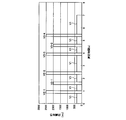
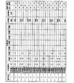
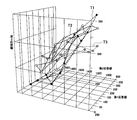
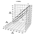
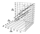
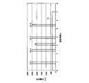
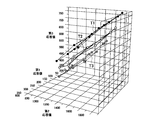
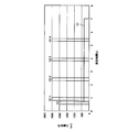
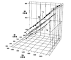
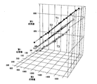
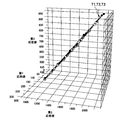
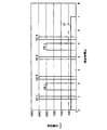
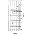
- FIG. 1 It is a disassembled perspective view of the biosensor shown as embodiment of this invention. It is sectional drawing of the biosensor shown as embodiment of this invention. It is a top view of the blood component measurement layer in the biosensor shown as an embodiment of the present invention. It is a block diagram which shows the structure of the measuring apparatus shown as embodiment of this invention. It is a figure which shows the 1st response value and 2nd response value with respect to a known glucose concentration and blood cell volume. It is a figure which shows the relationship between a 1st response value and a 2nd response value. It is a figure which shows the conversion matrix which shows the relationship between a 1st response value, a 2nd response value, and a 3rd response value.
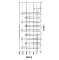
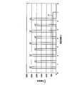
- FIG. 19 is a diagram showing a plurality of conversion matrices obtained when a voltage is applied as shown in FIG. 18 in the liquid sample measuring device shown as the embodiment of the present invention. It is a figure which shows the time change of the voltage value in the voltage application pattern by the liquid sample measuring device shown as embodiment of this invention.
- the liquid sample measuring device shown as embodiment of this invention it is a figure which shows the some conversion matrix obtained when a voltage is applied like FIG. It is a figure which shows the time change of the voltage value in the voltage application pattern by the liquid sample measuring device shown as embodiment of this invention.
- the liquid sample measuring device shown as embodiment of this invention it is a figure which shows the some conversion matrix obtained when a voltage is applied like FIG. It is a figure which shows the time change of the voltage value in the voltage application pattern as a comparative example. It is a figure which shows the some conversion matrix obtained when a voltage is applied like FIG. It is a figure which shows the time change of the voltage value in the voltage application pattern as a comparative example. It is a figure which shows the some conversion matrix obtained when a voltage is applied like FIG. It is a figure which shows the time change of the voltage value in the voltage application pattern by the liquid sample measuring device shown as embodiment of this invention.
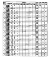
- FIG. 30 is a diagram showing a plurality of conversion matrices obtained when a voltage is applied as shown in FIGS. 28 and 29 in the liquid sample measuring device shown as the embodiment of the present invention. It is a figure which shows the time change of the voltage value in the voltage application pattern by the liquid sample measuring device shown as embodiment of this invention. It is a figure which shows the electrode in the voltage application pattern by the liquid sample measuring device shown as embodiment of this invention, an applied voltage, an application timing, and an application time.
- the liquid sample measuring device shown as embodiment of this invention it is a figure which shows the some conversion matrix obtained when a voltage is applied like FIG.31 and FIG.32. It is a figure which shows the time change of the voltage value in the voltage application pattern as a comparative example. It is a figure which shows the electrode in the voltage application pattern as a comparative example, an applied voltage, an application timing, and an application time. It is a figure which shows the some conversion matrix obtained when a voltage is applied like FIG.34 and FIG.35. It is a figure which shows the conversion matrix as a comparative example. It is a figure which shows the time change of the voltage value in the voltage application pattern by the liquid sample measuring device shown as embodiment of this invention. It is a figure which shows the time change of the voltage value in the voltage application pattern by the liquid sample measuring device shown as embodiment of this invention.
- biosensor 1 First, the biosensor 1 will be described.
- the biosensor 1 shown as an embodiment of the present invention includes each unit as shown in FIGS.
- FIG. 1 is an exploded perspective view of the biosensor 1.
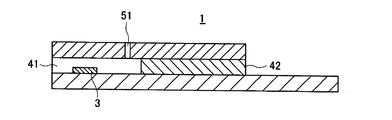
- FIG. 2 is a cross-sectional view of the biosensor 1.
- the biosensor 1 includes a blood component measurement layer 2, a reagent layer 3, a spacer layer 4, and a surface layer 5.
- the biosensor 1 is formed by laminating these layers.
- the biosensor 1 will be described below using a biosensor that measures glucose and blood cells as blood cell components, but is not limited thereto.
- the biosensor 1 can be attached to and detached from a liquid sample measuring device 6 described later.
- the biosensor 1 and the liquid sample measurement device 6 constitute a biosensor system.
- the liquid sample measuring device 6 measures the liquid component amount of the substrate contained in the blood as the sample spotted on the sample spotting portion 41 located at the tip of the biosensor 1.
- the liquid sample measuring device 6 displays the measured blood component amount (glucose concentration (first component amount) and blood cell amount (second component amount)) as a measurement result.
- the end of the biosensor 1 is inserted into the liquid sample measuring device 6 by the user. Thereafter, the liquid sample measuring device 6 applies a voltage to the electrodes of the biosensor 1 described later. In this state, blood is supplied to the sample spotting unit 41. When blood is spotted, the blood is sucked into the biosensor 1. The reagent layer 3 is dissolved by this blood. The liquid sample measurement device 6 detects an electrical change that occurs between the electrodes of the biosensor 1 and measures the amount of blood components.
- the biosensor 1 measures a specific blood component amount contained in human blood as a sample solution.
- This particular blood component quantity includes the glucose concentration.
- the measurement of the glucose concentration contained in the blood of the human body will be disclosed.
- the biosensor system in this embodiment can also measure lactic acid, cholesterol and other components by selecting an appropriate enzyme.
- Blood component measurement layer 2 is made of polyethylene terephthalate (PET), polycarbonate (PC), polyimide (PI), polyethylene (PE), polypropylene (PP), polystyrene (PS), polyvinyl chloride (PVC), polyoxymethylene (POM). ), Monomer cast nylon (MC), polybutylene terephthalate (PBT), methacrylic resin (PMMA), ABS resin (ABS), a conductive layer formed on an insulating substrate 20 made of glass or the like. .
- This conductive layer is made of a noble metal such as gold, platinum or palladium, or an electrically conductive material such as carbon.
- This conductive layer is formed by, for example, a screen printing method or a sputtering vapor deposition method.
- the conductive layer may be formed on the entire surface or at least a part of the substrate.
- This conductive layer may be coated with a polymer material for the purpose of preventing adhesion of impurities and preventing oxidation.
- the surface of the conductive layer can be coated by, for example, preparing a polymer material solution, dropping or applying the solution onto the surface of the conductive layer, and then drying the solution. Examples of drying include natural drying, air drying, hot air drying, and heat drying.
- the size of the insulating substrate 20 is not particularly limited, and is, for example, a total length of 5 to 100 mm, a width of 2 to 50 mm, and a thickness of 0.05 to 2 mm, preferably a total length of 7 to 50 mm and a width of 3 to 20 mm.
- the thickness is 0.1 to 1 mm, and more preferably, the total length is 10 to 30 mm, the width is 3 to 10 mm, and the thickness is 0.1 to 0.6 mm.
- the material of the spacer layer 4 is not particularly limited, and for example, the same material as that of the substrate 20 can be used.
- the size of the spacer layer 4 is not particularly limited, and is, for example, a total length of 5 to 100 mm, a width of 2 to 50 mm, and a thickness of 0.01 to 1 mm, preferably a total length of 7 to 50 mm, a width of 3 to 20 mm, and a thickness. It is 0.05 to 0.5 mm, and more preferably, the total length is 10 to 30 mm, the width is 3 to 10 mm, and the thickness is 0.05 to 0.25 mm.
- the spacer layer 4 is formed with an I-shaped cutout portion that becomes a sample spotting portion 41 for blood introduction.
- the surface layer 5 is an insulating substrate having an air hole 51 in the center.
- the surface layer 5 is disposed integrally with the blood component measurement layer 2 by sandwiching the spacer layer 4 having the sample spotting portion 41 as a notch between the blood component measurement layer 2.
- the surface layer 5, the spacer layer 4, and the blood component measurement layer 2 may be attached with an adhesive or heat-sealed.
- the adhesive include epoxy adhesives, acrylic adhesives, polyurethane adhesives, thermosetting adhesives (hot melt adhesives, etc.), UV curable adhesives, and the like.
- the material of the surface layer 5 is not particularly limited, and for example, the same material as that of the substrate 20 can be used. More preferably, the portion corresponding to the ceiling portion of the sample spotting portion 41 of the surface layer 5 is subjected to a hydrophilic treatment.
- the hydrophilic treatment include a method of applying a surfactant and a method of introducing a hydrophilic functional group such as a hydroxyl group, a carbonyl group, or a carboxyl group into the surface of the surface layer 5 by plasma treatment or the like.
- the size of the surface layer 5 is not particularly limited, and is, for example, a total length of 5 to 100 mm, a width of 3 to 50 mm, and a thickness of 0.01 to 0.5 mm, preferably a total length of 10 to 50 mm, a width of 3 to 20 mm, and a thickness. It is 0.05 to 0.25 mm, more preferably 15 to 30 mm in total length, 5 to 10 mm in width, and 0.05 to 0.1 mm in thickness.
- the surface layer 5 is preferably formed with air holes 51.
- the shape is, for example, a circle, an ellipse, or a polygon
- the size is, for example, a maximum diameter of 0.01 to 10 mm, preferably Has a maximum diameter of 0.05 to 5 mm, more preferably a maximum diameter of 0.1 to 2 mm.
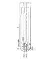
- FIG. 3 is a top view of the blood component measurement layer 2 in the biosensor 1.
- the blood component measurement layer 2 is formed with a first electrode pair including a first working electrode 21 (C) and a first counter electrode 22 (E).
- the 1st working electrode 21 and the 1st counter electrode 22 are arrange
- a second electrode pair including a second working electrode 23 (A) and a second counter electrode 24 (G) is formed.
- the second working electrode 23 is disposed at a position not in contact with the oxidoreductase and mediator of the reagent layer 3 described later.
- the second counter electrode 24 is disposed at a position in contact with the oxidoreductase and mediator of the reagent layer 3 to be described later and not in contact with the first working electrode 21.
- the blood component measurement layer 2 is formed with a detection electrode 25 for detecting the introduction of blood.
- the first working electrode 21, the first counter electrode 22, the second working electrode 23, the second counter electrode 24, and the detection electrode 25 are in a state in which the biosensor 1 is inserted into the liquid sample measuring device 6. 6 is electrically connected.
- a voltage is applied between the first working electrode 21 and the first counter electrode 22 with the first working electrode 21 as a positive electrode and the first counter electrode 22 as a negative electrode. (First voltage) is applied.
- the second working electrode 23 When measuring the second current value that is highly dependent on the blood cell volume, the second working electrode 23 is used as a positive electrode, the second counter electrode 24 is used as a negative electrode, and a voltage is applied between the second working electrode 23 and the second counter electrode 24. (Second voltage) is applied in a pulsed manner.
- This pulse shape includes modes such as a rectangular wave and a triangular wave. Details of the voltage application will be described later.
- the non-interference part 26 in which the electroconductive layer is not formed is provided.
- the non-interference part 26 separates the first working electrode 21 and the second counter electrode 24. Thereby, the non-interference part 26 suppresses that the mediator produced in the 2nd counter electrode 24 flows into the 1st working electrode 21 at the time of measurement of a 2nd electric current value.
- a third electrode pair is formed in the blood component measurement layer 2.
- the third electrode pair includes a second working electrode 23 (A, third working electrode) and a third counter electrode 27 (F, third counter electrode).
- a voltage (a third voltage) is applied to.
- the third counter electrode 27 is not limited to the blood introduction side (left side in FIG. 3) of the biosensor 1, but is on the detection electrode 25 side (however, excluding the portion where the reagent layer 3 is disposed, right side in FIG. 3). May be.
- an identification unit for identifying the biosensor 1 by the liquid sample measurement device 6 may be formed of electrodes.
- the identification unit has a shape that identifies the type of biosensor 1 and the difference in output characteristics for each production lot.
- the identification unit is formed on the end side of the biosensor 1, for example, and can be read by the liquid sample measurement device 6.
- the spacer layer 4 is disposed so as to cover the electrodes 21 to 24, 26, 27 on the substrate 20 of the blood component measurement layer 2.
- the spacer layer 4 is a substrate 42 on which a rectangular sample spot 41 is provided at the center of the front edge.
- the sample supply path 10 of FIG. When blood is spotted on the sample spotting portion 41, the blood is sucked toward the air hole 51 of the surface layer 5 in the right direction in FIGS. As a result, blood is introduced into the first working electrode 21, the first counter electrode 22, and the second counter electrode 24.
- the reagent layer 3 is arranged between the blood component measurement layer 2 and the spacer layer 4 as shown in FIG.
- the reagent layer 3 is formed by applying a reagent containing an enzyme, a mediator (electron acceptor), an amino acid, a sugar alcohol, and the like.
- the reagent layer 3 is in contact with the first working electrode 21 and the first counter electrode 22 exposed from the sample spotting portion 41 of the spacer layer 4.
- the reagent layer 3 selectively contains a polymer material, an enzyme stabilizer, a crystal homogenizer, and the like as optional components.
- a surface layer 5 is disposed via a spacer layer 4 leaving one end.
- glucose oxidase, lactate oxidase, cholesterol oxidase, cholesterol esterase, uricase, ascorbate oxidase, bilirubin oxidase, glucose dehydrogenase, lactate dehydrogenase, lactate dehydrogenase and the like can be used.
- the amount of the oxidoreductase is, for example, from 0.01 to 100 U, preferably from 0.05 to 10 U, more preferably from 0.1 to 100 U per biosensor or per measurement. 1-5U.
- glucose oxidase and glucose dehydrogenase are preferable as the oxidoreductase.
- ferricyanide is preferable, and potassium ferricyanide is more preferable.
- mediators p-benzoquinone and its derivatives, phenazine methosulfate, methylene blue, ferrocene and its derivatives can be used besides potassium ferricyanide.
- the biosensor 1 of the present embodiment uses, for example, glucose oxidase as an oxidoreductase supported on the reagent layer 3 and potassium ferricyanide as a mediator in order to measure glucose concentration (blood component) in the blood of a human body. .
- the oxidoreductase and the mediator are dissolved in the blood as the sample solution. Then, an enzyme reaction proceeds with glucose, which is a substrate in blood, and the mediator is reduced to produce ferrocyanide (potassium ferrocyanide in this embodiment). After the completion of the reaction, the reduced mediator is electrochemically oxidized, and a response value (first response value (mV)) highly dependent on the glucose concentration in blood is measured from the current obtained at this time. .
- first response value (mV) highly dependent on the glucose concentration in blood is measured from the current obtained at this time.
- blood cells mean red blood cells, white blood cells, platelets and combinations thereof contained in blood, but preferably red blood cells.
- the amount of blood cells means, for example, the ratio (volume ratio) of red blood cells in blood, preferably a hematocrit (Hct) value.
- the liquid sample measurement device 6 performs measurement using the biosensor 1 that oxidizes and reduces blood components contained in the blood by oxidoreductase when blood is introduced.
- the liquid sample measuring device 6 measures the glucose concentration and the blood cell amount as the blood component amount, and measures a temperature equivalent value that is a value corresponding to the temperature of the biosensor 1.
- the liquid sample measuring device 6 is connected to electrodes A to F provided at the end of the biosensor 1 in a state where the biosensor 1 is inserted into the liquid sample measuring device 6.
- Electrode C corresponds to first working electrode 21
- electrode E corresponds to first counter electrode 22
- electrode A corresponds to second working electrode 23
- electrode G corresponds to second counter electrode 24
- electrode D corresponds to detection electrode 25
- electrode F corresponds to third counter electrode 27.
- the liquid sample measuring device 6 includes a plurality of connectors 61 to 66 and switches 67 to 71, a current / voltage conversion circuit 72, an A / D conversion circuit 73, a CPU 74, an LCD 75, and a data storage unit 76 (storage means).
- the liquid sample measuring device 6 includes temperature measuring units 81 and 82 (temperature detecting means) for measuring the temperature in the device and switches 83 and 84 for the temperature measuring units 81 and 82.
- the connectors 62 and 64 and the switches 67 and 68 connected to the first counter electrode 22 and the second counter electrode 24 serving as negative electrodes are grounded.
- the temperature measuring unit 81 and the temperature measuring unit 82 each measure the temperature in the liquid sample measuring device 6 as the ambient temperature of the introduced blood. It is desirable that the temperature measuring units 81 and 82 measure the temperature at a position close to the biosensor 1 inserted into the liquid sample measuring device 6, for example.
- the temperature measurement values measured by the temperature measurement units 81 and 82 are supplied to the CPU 74.
- the CPU 74 compares the two temperature measurement results. When the temperature difference is not within the predetermined threshold value, it is determined that one of the temperature measuring units 81 and 82 has failed. Thereby, the failure detection of the liquid sample measuring device 6 is performed accurately and easily. In addition, measurement errors due to irregular temperature measurement are avoided.
- the temperature measurement timing may be immediately after the introduction of blood is detected by the detection electrode 25 or when the temperature of the blood introduced into the biosensor 1 is stabilized.
- the liquid sample measuring device 6 may not include the temperature measuring units 81 and 82.
- the liquid sample measuring device 6 only needs to include the temperature measuring units 81 and 82 only when the measured temperature is used in addition to the temperature equivalent value described later.
- the connectors 61 to 66 are connected to the electrodes A and C to G of the biosensor 1, respectively.
- the switches 67 to 71 are connected to connectors 62 to 66, respectively.
- the on / off state of the switches 67 to 71 is controlled by the CPU 74.
- the switch 67 is turned on in order to apply a voltage between the electrode C connected to the first working electrode 21 and the electrode E connected to the first counter electrode 22.
- the switches 68 and 69 are turned on in order to apply a voltage between the electrode A connected to the second working electrode 23 and the electrode G connected to the second counter electrode 24.
- the voltage applied between the first working electrode 21 and the first counter electrode 22 and the voltage applied between the second working electrode 23 and the second counter electrode 24 can be changed.
- the switch 70 is turned on to apply a voltage to the electrode D connected to the detection electrode 25.
- the switches 68 and 71 are turned on to apply a voltage between the electrode A connected to the second working electrode 23 and the electrode F connected to the third counter electrode 27.
- the current / voltage conversion circuit 72 is connected to the connectors 61 to 66 and the temperature measuring units 81 and 82.
- the current / voltage conversion circuit 72 is supplied with a current flowing between the first working electrode 21 and the second working electrode 23 and the other electrodes.
- the current / voltage conversion circuit 72 is supplied with a current corresponding to the ambient temperature measured by the temperature measuring units 81 and 82.
- the current / voltage conversion circuit 72 converts the supplied current into a voltage.
- the converted voltage value is supplied to the A / D conversion circuit 73.
- the A / D conversion circuit 73 is supplied with a voltage value from the current / voltage conversion circuit 72.
- the A / D conversion circuit 73 converts the supplied voltage value into pulsed digital data and outputs it to the CPU 74.
- the CPU 74 controls each part included in the liquid sample measuring device 6.
- the CPU 74 controls to turn on or off the switches 67 to 71 when measuring the glucose concentration, blood cell volume, and temperature equivalent value.
- the CPU 74 controls the voltage value applied to each electrode pair (control means). Specifically, the CPU 74 controls the voltage values and application periods of the first voltage, the second voltage, and the third voltage. Further, the CPU 74 controls measurement timings for measuring the first current value, the second current value, and the third current value.
- the CPU 74 has a first response value (mV) corresponding to the first current value, a second response value (mV) corresponding to the second current value, and Then, a third response value (mV) corresponding to the third current value is calculated.
- the CPU 74 converts the calculated first response value, second response value, and third response value into glucose concentration, blood cell volume, and temperature equivalent value of the biosensor 1.
- the CPU 74 determines the glucose concentration, the blood cell volume based on the first response value, the second response value, and the third response value obtained for the blood whose glucose concentration, blood cell volume, and biosensor 1 temperature are known.
- the temperature equivalent value of the biosensor 1 is obtained. The process of obtaining the glucose concentration, the blood cell volume, and the temperature equivalent value of the biosensor 1 from the first response value, the second response value, and the third response value will be described later.
- the LCD 75 is an LCD (Liquid Crystal Display: output unit) that displays measurement values calculated by the CPU 74.
- the data storage unit 76 stores data that can be referred to by the CPU 74.
- the data storage unit 76 stores recording data for the CPU 74 to calculate the glucose concentration.
- the recorded data is obtained by measuring the first current value, the second current value, and the third current value for each blood and temperature having a known glucose concentration and blood cell volume value, and the first current value corresponding to each current value.
- the response value, the second response value, and the third response value are included.
- the liquid sample measuring device 6 first detects the introduction of blood by the detection electrode 25 when measuring the glucose concentration, the blood cell volume, and the temperature equivalent value of the biosensor 1.
- a voltage (first voltage) is applied between the first working electrode 21 and the first counter electrode 22 (first electrode pair).
- the switch 67 is turned on by the CPU 74 so that the voltage is applied.
- the CPU 74 detects a redox current (first response value) generated by redox (first current value measuring means). The conversion process of the first response value will be described later.
- a voltage (second voltage) is applied between the second working electrode 23 and the second counter electrode 24 (second electrode pair).
- the switches 68 and 69 are turned on by the CPU 74 so as to be applied. In this state, the CPU 74 detects a second current value generated when a voltage is applied to the second working electrode 23 and the second counter electrode 24 (second current value measuring means).
- the liquid sample measurement device 6 When the liquid sample measurement device 6 obtains the third current value and measures the third response value, the liquid sample measurement device 6 applies a voltage between the second working electrode 23 and the third counter electrode 27 as the third electrode pair. Then, a third current value is obtained (third current value measuring means).
- the CPU 74 calculates the measured first component amount, the second component amount, and the temperature equivalent value of the biosensor 1 based on the measured first response value, second response value, and third response value (calculation means). ). At this time, the CPU 74 refers to the recording data.
- the CPU 74 includes a plurality of recorded data including the first response value, the second response value, and the third response value stored in the data storage unit 76, the measured first response value, the second response value, and The measurement data including the third response value is compared.
- the CPU 74 calculates, as the first component amount (glucose concentration) of blood introduced into the biosensor 1, the first component amount of blood that has obtained recorded data that is most approximate to the measurement data.
- the CPU 74 calculates, as the second component amount (blood cell amount) of blood introduced into the biosensor 1, the second component amount of blood that has obtained recorded data that is closest to the measurement data.
- the CPU 74 calculates the temperature equivalent value of the biosensor 1 when the recorded data closest to the measurement data is obtained as the temperature equivalent value of the biosensor 1 at the time of measurement.
- the first response value, the second response value, and the third response value are obtained as the first component amount, the second component amount, and the temperature equivalent value of the biosensor 1. Will be described.
- the first response value of the liquid sample measuring device 6 that is predicted to be supplied to the CPU 74 is as shown in FIG. 5, for example.
- the CPU 74 uses 120 as the first response value as the current value and the second as the current value. It is predicted that 1250 will be obtained as a response value.
- Such predicted values of the first response value and the second response value can be obtained by preparing blood whose glucose concentration and blood cell volume have been adjusted in advance and measuring with the biosensor 1 and the liquid sample measuring device 6.
- the first response value and the second response value plotted on a line connecting points obtained from the same known glucose concentration can be converted into the known glucose concentration and blood cell volume. Therefore, using the conversion matrix, the glucose concentration and the blood cell volume can be obtained from the first response value and the second response value obtained from unknown blood.
- the ratio between the respective first response values at the glucose concentrations of 100 mg / dl and 200 mg / dl in the conversion matrix (A: Take B). Converted from this ratio, a glucose concentration of 138 mg / dl can be obtained in blood from which the first response value and the second response value indicated by white circles in FIG. 6 are obtained.
- the first response value and the second response value indicated by white circles in FIG. 6 are obtained by taking the ratio between the respective second response values at the blood cell volume (Hct) 25% and 65% in the conversion matrix. An unknown blood cell amount in the obtained blood can be obtained.
- the glucose concentration and blood cell volume can be converted from the first response value and the second response value.
- the conversion matrix can include a third response value as will be described later. Accordingly, if the first response value, the second response value, and the third response value are obtained from the blood using the liquid sample measuring device 6, the blood glucose concentration, the blood cell volume, and the temperature of the biosensor 1 are equivalent. A value can be obtained.
- the liquid sample measuring device 6 measures the first response value, the second response value, and the third response value from the blood.
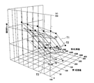
- the relationship among the first response value, the second response value, and the third response value is, for example, as shown in FIG.
- FIG. 7 shows a conversion matrix representing the relationship among the first response value (mV), the second response value (mV), and the third response value (mV) for each temperature T1, T2, and T3 (° C.) of the biosensor 1. It is shown in.
- the conversion matrix in FIG. 7 uses the blood sample measuring device 6 to obtain the first response value and the second response value using blood in which the temperature (° C.) of the biosensor 1 is known in advance and the glucose concentration and blood cell volume are known. And a third response value was obtained.
- T1 is 20 ° C.
- T2 is 25 ° C.
- T3 is 30 ° C.
- the plurality of conversion matrices do not intersect each other. That is, if the first response value, the second response value, and the third response value can be measured using blood whose glucose concentration and blood cell volume are unknown, the glucose concentration, blood cell volume, and The temperature equivalent value of the biosensor 1 can be obtained.
- the liquid sample measuring device 6 cannot obtain a unique glucose concentration, blood cell volume, and temperature equivalent value of the biosensor 1.
- the liquid sample measuring device 6 records data (converted) including a first response value, a second response value, and a third response value obtained using blood having a known glucose concentration and blood cell volume as shown in FIG.
- the matrix is stored for each of T1, T2 and T3 (° C.) of the temperature of the biosensor 1.
- the liquid sample measuring device 6 controls the first voltage and the application time applied between the first working electrode 21 and the first counter electrode 22. In addition to this, the liquid sample measuring device 6 controls the second voltage and the application time applied between the second working electrode 23 and the second counter electrode 24. Further, the liquid sample measuring device 6 applies a third voltage and an application time applied between the second working electrode 23 and the third counter electrode 27. Furthermore, the liquid sample measuring device 6 controls the measurement timings for measuring the first response value, the second response value, and the third response value, respectively. Means for performing such control is also referred to as control means.
- the first voltage, the second voltage, and the third voltage are applied as in the case of obtaining a conversion matrix that does not cross each other as shown in FIG.
- Two response values and a third response value are measured.
- the conversion including the first response value, the second response value, and the third response value closest to the measurement data by comparing the conversion matrix of FIG. 7 with the measured first response value, the second response value, and the third response value. Get the matrix.
- the liquid sample measuring device 6 can calculate the glucose concentration, blood cell volume, and biosensor 1 temperature when the conversion matrix is obtained as the unknown blood glucose concentration, blood cell volume, and biosensor 1 temperature.
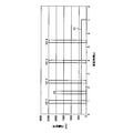
- the liquid sample measuring device 6 controls the voltage values and application times of the first voltage, the second voltage, and the third voltage, for example, as shown in FIG.
- the liquid sample measurement device 6 starts measuring current.
- the liquid sample measuring device 6 applies the first voltage V1 from the start of measurement to the end of measurement.
- the liquid sample measuring device 6 applies the second voltages V2-1, V2-2, V2-3 and V2-4 for a plurality of times in a pulse manner.
- the liquid sample measuring device 6 applies the third voltage V3 after the first second voltage V2-1 and before the second second voltage V2-2.
- the 2nd voltage V2 when naming a some 2nd voltage generically, it only calls "the 2nd voltage V2."
- the liquid sample measuring device 6 changes the voltage application electrode, the application voltage, the application time, and the application timing.
- the first voltage V1 is applied between the first working electrode 21 (C) and the first counter electrode 22 (E).
- the first voltage V1 is about 350 mV.
- Each second voltage V2 is applied between the second working electrode 23 (A) and the second counter electrode 24 (G).
- Each second voltage V2 is about 2500 mV.
- the application time of each second voltage V2 is about 0.2 seconds.
- the third voltage V3 is applied between the second working electrode 23 (A) and the third counter electrode 27 (F). This third voltage V3 is about 2000 mV. The application time of the third voltage V3 is 0.2 seconds.
- the liquid sample measuring device 6 By applying the first voltage V1, the second voltage V2, and the third voltage V3 of the applied voltage, the application timing, and the application time, the liquid sample measuring device 6 causes the first response value and the second response for blood. A value and a third response value are obtained.
- the liquid sample measuring apparatus 6 is configured to perform the operation of obtaining the first response value, the second response value, and the third response value on blood having a known glucose concentration and blood cell volume at a known temperature, as shown in FIG. A simple conversion matrix can be obtained. For example, when blood whose glucose concentration and blood cell volume is unknown is introduced into the biosensor 1, the liquid sample measuring device 6 has a first voltage V1, a second voltage V2, a third voltage, as shown in FIGS. A voltage V3 is applied.
- the liquid sample measuring device 6 can obtain the first response value, the second response value, and the third response value for the unknown blood. Finally, using the conversion matrix, the liquid sample measuring device 6 uniquely determines the glucose converted value and the blood cell volume converted value from the first response value, the second response value, and the third response value for the unknown blood. The temperature equivalent value of the biosensor 1 can be obtained.
- FIG. 10A shows a conversion matrix when the first voltage V1 is 350 mV.
- FIG. 10B shows a conversion matrix when the first voltage V1 is set to 500 mV.
- the liquid sample measuring device 6 applies the first voltage V1 also during the application time of the third voltage V3 and the application time of the second voltage V2.
- the liquid sample measuring device 6 does not apply the first voltage V1 during the application time of the third voltage V3 and the application time of the second voltage V2, and at the timing and period as shown in FIG. 11 and FIG.
- the conversion matrix shown in FIG. 13 was obtained as a result.
- a plurality of conversion matrices corresponding to the temperatures T1, T2 and T3 of the biosensor 1 intersect. Therefore, it is desirable that the liquid sample measuring device 6 obtains the second response value and the third response value by applying the second voltage V2 and the third voltage V3 while applying the first voltage V1.
- the liquid sample measuring device 6 may adjust the application time of the third voltage V3 applied between the second working electrode 23 and the third counter electrode 27. For example, as illustrated in FIG. 14, the liquid sample measurement device 6 applies the third voltage V ⁇ b> 3 over a longer period than illustrated in FIG. 8 to obtain a third response value.
- the liquid sample measuring device 6 applies the first voltage V1, the second voltage V2, and the third voltage V3, for example, at a timing and a period as shown in FIG.
- the conversion matrix when the third response value was obtained 0.2 seconds after application of the third voltage V3-1 was as shown in FIG.
- the conversion matrix when the third response value was obtained 0.5 seconds after application of the third voltage V3-1 was as shown in FIG.
- the liquid sample measuring device 6 obtains the third response value immediately after applying the third voltage V3-1, thereby obtaining a conversion matrix in which the third response value changes greatly for each temperature of the biosensor 1. be able to. That is, as shown in FIG. 16, the liquid sample measurement device 6 can obtain a conversion matrix of T1, T2, and T3 of the temperature of the biosensor 1 that does not cross each other.
- the liquid sample measuring device 6 applies the third voltage V3 after applying the second voltage V2.
- the liquid sample measuring device 6 applies the third voltage V3 after the first application of the second voltage V1-1.
- the liquid sample measuring device 6 can obtain a conversion matrix of T1, T2, and T3 of the temperature of the biosensor 1 that does not cross each other.
- the liquid sample measuring device 6 desirably applies the third voltage V3 after the second application of the second voltage V2-2. Also in this case, as shown in FIG. 21, the liquid sample measuring apparatus 6 uses the conversion matrix of T1, T2, and T3 of the temperature of the biosensor 1 that does not cross each other, and the glucose concentration, blood cell volume, and biosensor of unknown blood. A temperature equivalent value of 1 can be obtained. For example, as shown in FIG. 22, the liquid sample measuring device 6 applies the third voltage V3 after the third application of the second voltage V2-3. Also in this case, as shown in FIG. 23, the liquid sample measuring device 6 can obtain a conversion matrix of T1, T2, and T3 of the temperature of the biosensor 1 that does not cross each other.
- the liquid sample measuring apparatus 6 receives the third response as shown in FIG. A conversion matrix of T1, T2, and T3 for each temperature of the biosensor 1 with a small value difference was obtained. Therefore, it is desirable for the liquid sample measuring device 6 to apply the third voltage V3 after the second voltage V2.
- the liquid sample measuring device 6 applies the third voltage V3 before the first application of the second voltage V2-1 and when the first voltage V1 is not applied. Then, as shown in FIG. 27, the conversion matrices of T1, T2, and T3 for each temperature of the biosensor 1 cross each other. Therefore, it is desirable for the liquid sample measuring device 6 to apply the third voltage V3 when the first voltage V1 is applied.
- the liquid sample measuring device 6 uses the second working electrode 23 as the working electrode and the third counter electrode 27 as the counter electrode when applying the third voltage V3, but it may be reversed.
- the liquid sample measuring device 6 applies the third voltage V3 as shown in FIG. 28, for example.
- the liquid sample measuring apparatus 6 applies the first third voltage V3 with the second working electrode 23 (A) as the working electrode and the third counter electrode 27 (F) as the counter electrode.
- the second to fourth third voltage V3 ' is applied to the liquid sample measuring device 6 using the second working electrode 23 (A) as a counter electrode and the third counter electrode 27 (F) as a working electrode.
- the liquid sample measurement device 6 does not cross the temperature T1, T2, A conversion matrix of T3 can be obtained.
- the liquid sample measuring device 6 is not limited to the above-described embodiment, and the electrode to which the second voltage V2 is applied may be changed.
- the second voltage V2 is applied between the second working electrode 23 (A) and the second counter electrode 24 (G).
- the third voltage V3 is applied between the second working electrode 23 (A) and the third counter electrode 27 (F).
- the liquid sample measuring device 6 that applies the second voltage V2 and the third voltage V3 applies the second voltage to the other electrode pairs.
- the liquid sample measuring device 6 applies the second voltage V2 'with the third counter electrode 27 (F) as a working electrode and the second counter electrode 24 (G) as a counter electrode.
- the liquid sample measuring device 6 has the temperatures T1, T2, and T3 of the biosensor 1 that do not cross each other. A conversion matrix can be obtained.
- the liquid sample measuring device 6 it is desirable for the liquid sample measuring device 6 to make the electrode pair to which the third voltage V3 is applied different from the electrode pair to which the second voltage V2 is applied.
- the liquid sample measuring device 6 has a second voltage V2-1, a third voltage V3-1, a second voltage V2-2, a third voltage V3-2, a second voltage after the start of measurement.
- the voltage V2-3 is applied in this order.
- the liquid sample measuring device 6 applies the second third voltage V3-2 to the third counter electrode 27 (F) and the second working electrode 23 (A), for example, as shown in FIG.
- the liquid sample measuring device 6 applies the other second voltage V2 and third voltage V3-1 between the second working electrode 23 (A) and the second counter electrode 24 (G).
- the second voltage V2 is applied to the second working electrode 23 (A) and the second counter electrode 24 (G).
- the third voltage V3-1 a voltage having the same value as that of the third voltage V3-2 is applied between the second working electrode 23 (A) and the second counter electrode 24 (G).
- the third response value does not vary much even at different temperatures of the biosensor 1.
- the conversion matrices of T1, T2, and T3 of the temperature of the biosensor 1 overlap each other. Therefore, it is desirable that the liquid sample measuring device 6 changes the electrode pair to which the second voltage V2 and the third voltage V3 are applied.
- the blood glucose concentration, the blood cell volume, and the biosensor using the first response value, the second response value, and the third response value.
- a temperature equivalent value of 1 can be measured.
- the temperature (° C.) of the biosensor 1 must be constant in each conversion matrix. I don't get it. In this case, when there is a discrepancy between the temperature obtained by the liquid sample measuring device 6 and the temperature of the portion where the first and second response values are actually measured, there is no means for reflecting that information, so accurate conversion is possible. It is difficult to get a value.
- the glucose conversion value, the blood cell volume conversion value, the biosensor are referred to with reference to the conversion matrix in which the third response value is added as well as the first response value and the second response value. A temperature equivalent value of 1 can be obtained. Therefore, the glucose conversion value can be obtained with high accuracy by the liquid sample measuring device 6 of the present invention.
- the third counter electrode 27 is provided in order to obtain the third response value, and between the third counter electrode 27 (counter electrode) and the second working electrode 23 (working electrode). A third voltage is applied.
- the electric current obtained by applying a 3rd voltage between the 2nd working electrode 23 and the 3rd counter electrode 27 is detectable as a 3rd response value.
- the 3rd response value considered to depend on the temperature of the reaction part in the biosensor 1 can be obtained.
- the liquid sample measuring device 6 not only the first response value mainly depending on the glucose concentration, the second response value mainly depending on the blood cell volume, but also the third degree highly dependent on the temperature of the biosensor 1 is obtained.
- the glucose concentration can be calculated using the response value.
- the liquid sample measuring device 6 it is desirable to obtain the third current value (third response value) when the first voltage is applied.
- the third current value third response value
- a conversion matrix that does not overlap in the third response value direction is obtained, and using this conversion matrix, blood glucose concentration, blood cell volume, and biosensor A temperature equivalent value of 1 can be obtained.
- the liquid sample measuring device 6 it is desirable to obtain the third current value (third response value) after applying the second voltage.
- the third current value third response value
- a conversion matrix that does not cross each other is obtained, and using this conversion matrix, the blood glucose concentration, the blood cell volume, and the temperature of the biosensor 1 are equivalent. A value can be obtained.
- the liquid sample measuring device 6 for example, the first current value, the second current value obtained for the liquid for each of the known first component amount and the second component amount, and for each temperature, and The recording data recording the third current value is stored. Then, the liquid sample measuring device 6 compares the recorded data with the measurement data including the first current value, the second current value, and the third current value, and is closest to the measurement data.
- the first component amount of the liquid from which the recording data is obtained can be calculated as the first component amount of the liquid introduced into the biosensor 1.
- the blood cell volume and the temperature corresponding to the temperature of the biosensor 1 that are closest to the measurement data are obtained. Can be calculated as a value.
- the glucose concentration with high blood accuracy can be obtained only by the operation of comparing the first response value, the second response value, and the third response value of the recording data and the measurement data.
- the blood cell volume and the temperature equivalent value of the biosensor 1 can be obtained.
- an electrode pair (third electrode pair) for obtaining a third response value is constituted by a first electrode that does not contact blood and an electrode that does not contact liquid among electrode pairs for measuring the second response value. According to the liquid sample measuring device 6 that has been performed, it is possible to obtain a third response value that depends mainly on the temperature in the reaction part of the biosensor 1.
- the third voltage is applied to the third electrode pair in order to obtain the third current value (third response value), but another method is used to obtain the third current value. Also good.
- the CPU 74 controls the first voltage value applied between the first working electrode 21 for measuring the first current value and the first counter electrode 22, thereby making the third current value different from the first current value and the second current value. A current value may be obtained.
- the CPU 74 can obtain the third current value by applying the first voltage between the first working electrode 21 and the first counter electrode 22 with reference to a value obtained in advance through experiments or the like.
- the third current value is obtained by applying the first voltage set so as to be considered to depend mainly on the temperature of the biosensor 1.
- a voltage value in a predetermined range, a predetermined application timing, and a predetermined application time that are obtained in advance through experiments or the like are selected.
- the first voltage for obtaining the first response value is about 1 to 600 mV.
- the first voltage in such a range is a voltage range suitable for oxidizing and reducing blood.
- the first voltage for obtaining the third response value that easily depends on the temperature of the biosensor 1 is higher than the voltage of the first response value, preferably higher than 600 mV and preferably 2000 mV.
- the range of the first voltage for obtaining this high third response value is a voltage that electrolyzes water. Therefore, when the liquid sample measurement device 6 obtains the temperature equivalent value by applying the first voltage, for example, after the measurement of the first response value, the liquid sample measurement device 6 applies the first voltage higher than the first response value to obtain the third response value. Get.
- the first response value can be obtained by controlling the first voltage V1.
- the liquid sample measuring device 6 uses the first response value, the second response value, and the third response value to obtain the blood glucose converted value, the blood cell volume converted value, and the temperature equivalent value of the biosensor 1 with high accuracy. It can be measured.
- the liquid sample measuring device 6 is measured by a plurality of first current values, a plurality of second current values, a third current value, a fourth current value, and temperature measuring units 81 and 82.
- the temperature With reference to the temperature, the blood glucose concentration, the blood cell volume, and the temperature equivalent value of the biosensor 1 may be obtained.
- the CPU 74 controls, for example, the respective voltage values and application periods of the first voltage, the second voltage, and the third voltage.
- the CPU 74 controls, for example, measurement timings for measuring the first current value, the second current value, and the third current value, respectively, and sets the fourth current value at a timing different from the first current value and the second current value.
- the measurement timing is controlled so as to measure by applying the first voltage. For example, it is desirable to obtain the fourth current value (fourth response value) that is highly dependent on the glucose concentration when the first voltage is applied.
- a fourth voltage is applied between the third counter electrode 27 and the second working electrode 23. This fourth voltage is preferably substantially equal to the third voltage.
- the fourth current value is preferably measured at a timing different from the first current value, the second current value, and the third current value as described above. Specifically, for example, in FIG. 38, the fourth voltage V4-1 may be applied, and the fourth response value may be measured during the application.
- this fourth current value each current value obtained at a different time is used so that information on temporal changes such as the temperature environment can be obtained as blood glucose concentration, blood cell volume, and temperature equivalent value of the biosensor 1. There is an advantage that it can be added to the conversion.
- the fifth current value (fifth response value) that is highly dependent on the temperature of the biosensor 1 when the first voltage is applied.
- a fifth voltage is applied between the third counter electrode 27 (working electrode) and the second work electrode 23 (counter electrode).
- the fifth voltage is preferably substantially equal to the third voltage.
- the third voltage V3 is applied with the second working electrode 23 (A) as the working electrode and the third counter electrode 27 (F) as the counter electrode, and the fifth voltage V5 has the working electrode and the counter electrode reversed.
- the fifth current value (the fifth response value) is preferably measured at a timing different from the second current value and the third current value.
- the fifth voltage V5-1 may be applied, and the fifth current value may be measured during the application. Even when this fifth current value is used, there is an advantage that the same result as that obtained when the third current value is used can be obtained.
- the CPU 74 uses, for example, a set of the first current value, the second current value, the fourth current value, and / or the fifth current value generated when the first voltage, the second voltage, and the fourth voltage are applied, respectively.
- the first component amount, the second component amount, and the first temperature equivalent value corresponding to the temperature of the biosensor 1 are calculated. This operation corresponds to the first calculation means and the first calculation step.
- the liquid sample measuring device 6 includes, for example, a known first component amount and second component amount liquid, and a first current value, a second current value, a first current value obtained using the liquid for each temperature.
- First recording data in which four current values and / or fifth current values are recorded is stored (first storage means).
- the first calculation means includes the first recording data, the measured first current value, the measured second current value, and the measured fourth current value and / or the fifth current value. And compare. And the 1st calculating means introduce
- the CPU 74 uses the first current value, the second current value, and the third current value that are generated when, for example, the first voltage, the second voltage, and the third voltage are applied, respectively, to use the first voltage included in the liquid.
- a component amount, a second component amount, and a second temperature equivalent value corresponding to the temperature of the biosensor 1 are calculated. This operation corresponds to the second calculation means and the second calculation step.
- the liquid sample measuring device 6 records, for example, the first current value, the second current value, and the third current value for each known liquid having the first component amount and the second component amount, and the temperature. Second recording data is stored (second storage means).
- the second calculation means compares the second recorded data with the measured data including the measured first current value, the measured second current value, and the measured third current value. Then, the first component amount of the liquid, the second component amount, and the temperature of the biosensor 1 from which the record data that is most approximate to the measurement data are obtained are used as the first component amount of the liquid introduced into the biosensor 1. , The second component amount, and the second temperature equivalent value of the biosensor 1 can be calculated.
- the CPU 74 recalculates the first component amount based on, for example, the first component amount calculated by the first calculating means and the first component amount calculated by the second calculating means. Further, the CPU 74 recalculates the second component amount based on, for example, the second component amount calculated by the first calculating unit and the second component amount calculated by the second calculating unit. Further, the CPU 74 recalculates the temperature of the biosensor 1 based on, for example, the temperature detected by the temperature measuring units 81 and 82 and the first temperature equivalent value and the second temperature equivalent value of the biosensor 1. These recalculations may take an average value, for example.
- the glucose concentration (first component amount) is added to the blood using the values obtained by the first computing means and the second computing means and the temperatures measured by the temperature measuring sections 81 and 82. ), The amount of blood cells (second component amount), and the temperature equivalent value of the biosensor 1 can be obtained. Therefore, according to the liquid sample measuring device 6, as described above, the blood glucose concentration (first component amount) and the blood cell volume with higher accuracy than the values obtained only by the first calculating means or the second calculating means. The (second component amount) and the temperature equivalent value of the biosensor 1 can be calculated.
Landscapes
- Health & Medical Sciences (AREA)
- Life Sciences & Earth Sciences (AREA)
- Chemical & Material Sciences (AREA)
- Hematology (AREA)
- Biochemistry (AREA)
- Immunology (AREA)
- Physics & Mathematics (AREA)
- Analytical Chemistry (AREA)
- Chemical Kinetics & Catalysis (AREA)
- General Health & Medical Sciences (AREA)
- General Physics & Mathematics (AREA)
- Electrochemistry (AREA)
- Pathology (AREA)
- Molecular Biology (AREA)
- Apparatus Associated With Microorganisms And Enzymes (AREA)
- Measuring Or Testing Involving Enzymes Or Micro-Organisms (AREA)
- Investigating Or Analysing Biological Materials (AREA)
- Investigating Or Analyzing Materials Using Thermal Means (AREA)
- Investigating Or Analyzing Materials By The Use Of Electric Means (AREA)
Abstract
Description
液体が導入されることにより当該液体に含まれる成分を酸化還元酵素によって酸化還元をするバイオセンサを用いて成分量を測定する液体試料測定装置であって、
前記バイオセンサを構成する第1電極対に第1電圧を印加したときに前記酸化還元によって生じる酸化還元電流を第1電流値として検出する第1電流値測定手段と、
前記バイオセンサを構成する第2電極対に第2電圧を印加したときに生じる電流を第2電流値として検出する第2電流値測定手段と、
前記バイオセンサを構成する第3電極対に第3電圧を印加したときに生じる電流を第3電流値として検出する第3電流値測定手段と、
前記第1電圧、前記第2電圧及び、前記第3電圧のそれぞれの電圧値及び印加期間を制御し、前記第1電極対に前記第1電圧を印加中に、前記第2電極対に前記第2電圧を、前記第3電極対に前記第3電圧をそれぞれ印加し、かつ、前記第1電流値、前記第2電流値及び、前記第3電流値を測定する測定タイミングをそれぞれ制御する制御手段と、
前記第1電圧、前記第2電圧及び、前記第3電圧をそれぞれ印加した時に生じた前記第1電流値、前記第2電流値及び、前記第3電流値の組を用いて、前記液体に含まれる第1成分量、第2成分量、及び、前記バイオセンサの温度に相当する値を演算する演算手段と
を備えることを特徴とする。
周囲の温度を検出する温度検出手段を更に備え、
前記第1電流測定手段が、前記第1電極対に前記第1電圧を印加中に、第4電流値をさらに検出し、
前記制御手段が、前記第4電流値を、前記第1電流値及び前記第2電流値とは異なるタイミングで測定するよう測定タイミングをさらに制御し、
前記演算手段は、
前記第1電圧及び前記第2電圧をそれぞれ印加した時に生じた前記第1電流値、前記第2電流値及び、前記第4電流値の組を用いて、前記液体に含まれる第1成分量、第2成分量、及び、前記バイオセンサの温度に相当する第1温度相当値を演算する第1演算手段と、
前記第1電圧、前記第2電圧及び、前記第3電圧をそれぞれ印加した時に生じた前記第1電流値、前記第2電流値及び、前記第3電流値の組を用いて、前記液体に含まれる第1成分量、第2成分量、及び、前記バイオセンサの温度に相当する第2温度相当値を演算する第2演算手段とを備え、かつ、
前記演算手段は、前記第1演算手段により演算された第1成分量及び前記第2演算手段により演算された第1成分量に基づいて第1成分量を再演算し、前記第1演算手段により演算された第2成分量及び前記第2演算手段により演算された第2成分量に基づいて第2成分量を再演算し、前記温度検出手段により検出された温度と前記第1温度相当値と前記第2温度相当値とに基づいて前記バイオセンサの温度を再演算すること
を特徴とする。
前記制御手段は、前記第1電流値測定手段により前記第1電極対に第1電圧を印加させているときに、前記第3電流値測定手段により前記第3電極対に前記第3電圧を印加して前記第3電流値を測定するよう制御することを特徴とする。
前記制御手段は、前記第2電流値測定手段によって前記第2電極対に第2電圧を印加させた後に、前記第3電流値測定手段により前記第3電極対に前記第3電圧を印加して前記第3電流値を測定するよう制御することを特徴とする。
既知量の第1成分及び第2成分を有する液体、並びに、温度ごとに、前記液体についての第1電流値、第2電流値、及び、第3電流値を記録した記録データを記憶した記憶手段を備え、
前記演算手段は、前記記録データと、測定された前記第1電流値、測定された前記第2電流値及び、測定された前記第3電流値を含む測定データとを比較して、当該測定データに最も近似している記録データを得た液体の第1成分量を、前記バイオセンサに導入された液体の第1成分量として演算すること
を特徴とする。
既知量の第1成分及び第2成分を有する液体、並びに、温度ごとに、前記液体についての第1電流値、第2電流値、及び、第4電流値を記録した記録データを記憶した第1記憶手段を備え、
前記第1演算手段は、前記記録データと、測定された前記第1電流値、測定された前記第2電流値及び、測定された前記第4電流値を含む測定データとを比較して、当該測定データに最も近似している記録データを得た液体の第1成分量、第2成分量、及び、前記バイオセンサの温度を、前記バイオセンサに導入された液体の第1成分量、第2成分量、及び、前記第1温度相当値として演算し、
既知量の第1成分及び第2成分を有する液体、並びに、温度ごとに、記液体についての第1電流値、第2電流値、及び、第3電流値を記録した記録データを記憶した第2記憶手段を備え、
前記第2演算手段は、前記記録データと、測定された前記第1電流値、測定された前記第2電流値及び、測定された前記第3電流値を含む測定データとを比較して、当該測定データに最も近似している記録データを得た液体の第1成分量、第2成分量、及び、前記バイオセンサの温度を、前記バイオセンサに導入された液体の第1成分量、第2成分量、及び、前記第2温度相当値として演算すること
を特徴とする。
前記第3電極対は、前記酸化還元酵素及びメディエータと接しない第1電極と、前記第2電流値測定手段における第2電極対のうち前記酸化還元酵素及びメディエータに接しない電極とにより構成されることを特徴とする。
前記第3電流値測定手段が、前記第3電流値と異なるタイミングで、前記バイオセンサを構成する第3電極対に第4電圧を印加したときに生じる電流を第4電流値として更に検出し、
前記演算手段が、前記第1電流値、前記第2電流値及び、前記第3電流値に加えて前記第4電流値を用いて、前記液体に含まれる第1成分量、第2成分量、及び、前記バイオセンサの温度に相当する値を演算する。
前記第3電流値測定手段が、前記第2電流値及び前記第3電流値と異なるタイミングで、前記バイオセンサを構成する第3電極対に第5電圧を印加したときに生じる電流を第5電流値として更に検出し、
前記演算手段が、前記第1電流値、前記第2電流値及び、前記第3電流値に加えて前記第5電流値を用いて、前記液体に含まれる第1成分量、第2成分量、及び、前記バイオセンサの温度に相当する値を演算する。
前記バイオセンサを構成する第1電極対に第1電圧を印加したときに前記酸化還元によって生じる酸化還元電流を第1電流値として検出する第1電流値測定工程と、
前記第1電極対に前記第1電圧を印加中に、前記バイオセンサを構成する第2電極対に第2電圧を印加したときに生じる電流を第2電流値として検出する第2電流値測定工程と、
前記第1電極対に前記第1電圧を印加中に、前記バイオセンサを構成する第3電極対に第3電圧を印加したときに生じる電流を第3電流値として検出する第3電流値測定工程と
前記第1電圧、前記第2電圧、及び前記第3電圧をそれぞれ印加した時に生じた前記第1電流値、前記第2電流値及び、前記第3電流値の組を用いて、前記液体に含まれる第1成分量、第2成分量、及び、前記バイオセンサの温度に相当する値を演算する工程を含むこと
を特徴とする。
周囲の温度を検出する温度検出工程を更に含み、
前記演算工程が、
前記第1電圧、前記第2電圧をそれぞれ印加した時に生じた前記第1電流値、前記第2電流値、前記第4電流値の組を用いて、前記液体に含まれる第1成分量、第2成分量、及び、前記バイオセンサの温度に相当する第1温度相当値を演算する第1演算工程と、
前記第1電圧、前記第2電圧、前記第3電圧をそれぞれ印加した時に生じた前記第1電流値、前記第2電流値、前記第3電流値の組を用いて、前記液体に含まれる第1成分量、第2成分量、及び、前記バイオセンサの温度に相当する第2温度相当値を演算する第2演算工程と、
前記第1演算工程により演算された第1成分量及び前記第2演算工程により演算された第1成分量に基づいて第1成分量を再演算し、前記第1演算工程により演算された第2成分量及び前記第2演算工程により演算された第2成分量に基づいて第2成分量を再演算し、前記温度検出工程により検出された温度と前記第1温度相当値と前記第2温度相当値とに基づいて前記バイオセンサの温度を再演算する再演算工程を含むこと
を特徴とする。
前記第3電流値測定工程が、前記第1電極対に第1電圧を印加させているときに、前記第3電流値を測定することを含む。
前記第3電流値測定工程が、前記第2電極対に第2電圧を印加させた後に、前記第3電流値を測定することを含む。
前記演算工程において、
既知量の第1成分及び第2成分を有する液体、並びに、温度ごとに前記液体についての第1電流値、第2電流値、及び、第3電流値を記録した記録データと、前記測定された第1電流値、前記測定された第2電流値、及び、前記測定された第3電流値とを含む測定データとを比較して、当該測定データに最も近似している記録データを得た液体の第1成分量を、前記バイオセンサに導入された液体の第1成分量として演算すること
を特徴とする。
前記演算工程が、
既知量の第1成分及び第2成分を有する液体、並びに、温度ごとに、前記液体についての第1電流値、第2電流値、及び、第4電流値を記録した第1記録データと、測定された前記第1電流値、測定された前記第2電流値及び、測定された前記第4電流値を含む測定データとを比較して、当該測定データに最も近似している記録データを得た液体の第1成分量、第2成分量、及び、前記バイオセンサの温度を、前記バイオセンサに導入された液体の第1成分量、第2成分量、及び、前記第1温度相当値として演算し、かつ、
既知量の第1成分及び第2成分を有する液体、並びに、温度ごとに、前記液体についての第1電流値、第2電流値、及び、第3電流値を記録した第2記録データと、測定された前記第1電流値、測定された前記第2電流値及び、測定された前記第3電流値を含む測定データとを比較して、当該測定データに最も近似している記録データを得た液体の第1成分量、第2成分量、及び、前記バイオセンサの温度を、前記バイオセンサに導入された液体の第1成分量、第2成分量、及び、前記第2温度相当値として演算することを含む。
前記第3電流値と異なるタイミングで、前記バイオセンサを構成する第3電極対に第4電圧を印加したときに生じる電流を第4電流値として検出する第4電流測定工程をさらに含み、
前記演算工程において、前記第1電流値、前記第2電流値及び、前記第3電流値に加えて前記第4電流値を用いて、前記液体に含まれる第1成分量、第2成分量、及び、前記バイオセンサの温度に相当する値が演算される。
前記第2電流値及び前記第3電流値と異なるタイミングで、前記バイオセンサを構成する第3電極対に第5電圧を印加したときに生じる電流を第5電流値として検出する第5電流測定工程をさらに含み、
前記演算手工程において、前記第1電流値、前記第2電流値及び、前記第3電流値に加えて前記第5電流値を用いて、前記液体に含まれる第1成分量、第2成分量、及び、前記バイオセンサの温度に相当する値が演算される。
6 液体試料測定装置
21 第1作用極
22 第1対極
23 第2作用極
24 第2対極
27 第3対極
76 データ記憶部
81,82 温度測定部
Claims (18)
- 液体が導入されることにより当該液体に含まれる成分を酸化還元酵素によって酸化還元をするバイオセンサを用いて成分量を測定する液体試料測定装置であって、
前記バイオセンサを構成する第1電極対に第1電圧を印加したときに前記酸化還元によって生じる酸化還元電流を第1電流値として検出する第1電流値測定手段と、
前記バイオセンサを構成する第2電極対に第2電圧を印加したときに生じる電流を第2電流値として検出する第2電流値測定手段と、
前記バイオセンサを構成する第3電極対に第3電圧を印加したときに生じる電流を第3電流値として検出する第3電流値測定手段と、
前記第1電圧、前記第2電圧及び、前記第3電圧のそれぞれの電圧値及び印加期間を制御し、前記第1電極対に前記第1電圧を印加中に、前記第2電極対に前記第2電圧を、前記第3電極対に前記第3電圧をそれぞれ印加し、かつ、前記第1電流値、前記第2電流値及び、前記第3電流値を測定する測定タイミングをそれぞれ制御する制御手段と、
前記第1電圧、前記第2電圧及び、前記第3電圧をそれぞれ印加した時に生じた前記第1電流値、前記第2電流値及び、前記第3電流値の組を用いて、前記液体に含まれる第1成分量、第2成分量、及び、前記バイオセンサの温度に相当する値を演算する演算手段と
を備えることを特徴とする液体試料測定装置。 - 請求項1に記載の液体試料測定装置であって、
周囲の温度を検出する温度検出手段を更に備え、
前記第1電流測定手段が、前記第1電極対に前記第1電圧を印加中に、第4電流値をさらに検出し、
前記制御手段が、前記第4電流値を、前記第1電流値及び前記第2電流値とは異なるタイミングで測定するよう測定タイミングをさらに制御し、
前記演算手段は、
前記第1電圧及び前記第2電圧をそれぞれ印加した時に生じた前記第1電流値、前記第2電流値及び、前記第4電流値の組を用いて、前記液体に含まれる第1成分量、第2成分量、及び、前記バイオセンサの温度に相当する第1温度相当値を演算する第1演算手段と、
前記第1電圧、前記第2電圧及び、前記第3電圧をそれぞれ印加した時に生じた前記第1電流値、前記第2電流値及び、前記第3電流値の組を用いて、前記液体に含まれる第1成分量、第2成分量、及び、前記バイオセンサの温度に相当する第2温度相当値を演算する第2演算手段とを備え、かつ、
前記演算手段は、前記第1演算手段により演算された第1成分量及び前記第2演算手段により演算された第1成分量に基づいて第1成分量を再演算し、前記第1演算手段により演算された第2成分量及び前記第2演算手段により演算された第2成分量に基づいて第2成分量を再演算し、前記温度検出手段により検出された温度と前記第1温度相当値と前記第2温度相当値とに基づいて前記バイオセンサの温度を再演算すること
を特徴とする液体試料測定装置。 - 前記制御手段は、前記第1電流値測定手段により前記第1電極対に第1電圧を印加させているときに、前記第3電流値測定手段により前記第3電極対に前記第3電圧を印加して前記第3電流値を測定するよう制御することを特徴とする請求項1又は請求項2に記載の液体試料測定装置。
- 前記制御手段は、前記第2電流値測定手段によって前記第2電極対に第2電圧を印加させた後に、前記第3電流値測定手段により前記第3電極対に前記第3電圧を印加して前記第3電流値を測定するよう制御することを特徴とする請求項1~3のいずれか一項に記載の液体試料測定装置。
- 既知量の第1成分及び第2成分を有する液体、並びに、温度ごとに、前記液体についての第1電流値、第2電流値、及び、第3電流値を記録した記録データを記憶した記憶手段を備え、
前記演算手段は、前記記録データと、測定された前記第1電流値、測定された前記第2電流値及び、測定された前記第3電流値を含む測定データとを比較して、当該測定データに最も近似している記録データを得た液体の第1成分量を、前記バイオセンサに導入された液体の第1成分量として演算すること
を特徴とする請求項1~4のいずれか一項に記載の液体試料測定装置。 - 既知量の第1成分及び第2成分を有する液体、並びに、温度ごとに、前記液体についての第1電流値、第2電流値、及び、第4電流値を記録した記録データを記憶した第1記憶手段を備え、
前記第1演算手段は、前記記録データと、測定された前記第1電流値、測定された前記第2電流値及び、測定された前記第4電流値を含む測定データとを比較して、当該測定データに最も近似している記録データを得た液体の第1成分量、第2成分量、及び、前記バイオセンサの温度を、前記バイオセンサに導入された液体の第1成分量、第2成分量、及び、前記第1温度相当値として演算し、
既知量の第1成分及び第2成分を有する液体、並びに、温度ごとに、前記液体についての第1電流値、第2電流値、及び、第3電流値を記録した記録データを記憶した第2記憶手段を備え、
前記第2演算手段は、前記記録データと、測定された前記第1電流値、測定された前記第2電流値及び、測定された前記第3電流値を含む測定データとを比較して、当該測定データに最も近似している記録データを得た液体の第1成分量、第2成分量、及び、前記バイオセンサの温度を、前記バイオセンサに導入された液体の第1成分量、第2成分量、及び、前記第2温度相当値として演算すること
を特徴とする請求項2~5のいずれか一項に記載の液体試料測定装置。 - 前記第3電極対は、前記酸化還元酵素及びメディエータと接しない第1電極と、前記第2電流値測定手段における第2電極対のうち前記酸化還元酵素及びメディエータに接しない電極とにより構成されることを特徴とする請求項1~6のいずれか一項に記載の液体試料測定装置。
- 前記第3電流値測定手段が、前記第3電流値と異なるタイミングで、前記バイオセンサを構成する第3電極対に第4電圧を印加したときに生じる電流を第4電流値として更に検出し、
前記演算手段が、前記第1電流値、前記第2電流値及び、前記第3電流値に加えて前記第4電流値を用いて、前記液体に含まれる第1成分量、第2成分量、及び、前記バイオセンサの温度に相当する値を演算する
請求項1~7のいずれか一項に記載の液体試料測定装置。 - 前記第3電流値測定手段が、前記第2電流値及び前記第3電流値と異なるタイミングで、前記バイオセンサを構成する第3電極対に第5電圧を印加したときに生じる電流を第5電流値として更に検出し、
前記演算手段が、前記第1電流値、前記第2電流値及び、前記第3電流値に加えて前記第5電流値を用いて、前記液体に含まれる第1成分量、第2成分量、及び、前記バイオセンサの温度に相当する値を演算する
請求項1~8のいずれか一項に記載の液体試料測定装置。 - 液体が導入されることにより当該液体に含まれる成分を酸化還元酵素によって酸化還元をするバイオセンサを用いて成分量を測定する液体試料測定方法であって、
前記バイオセンサを構成する第1電極対に第1電圧を印加したときに前記酸化還元によって生じる酸化還元電流を第1電流値として検出する第1電流値測定工程と、
前記第1電極対に前記第1電圧を印加中に、前記バイオセンサを構成する第2電極対に第2電圧を印加したときに生じる電流を第2電流値として検出する第2電流値測定工程と、
前記第1電極対に前記第1電圧を印加中に、前記バイオセンサを構成する第3電極対に第3電圧を印加したときに生じる電流を第3電流値として検出する第3電流値測定工程と
前記第1電圧、前記第2電圧、及び前記第3電圧をそれぞれ印加した時に生じた前記第1電流値、前記第2電流値及び、前記第3電流値の組を用いて、前記液体に含まれる第1成分量、第2成分量、及び、前記バイオセンサの温度に相当する値を演算する工程を含むこと
を特徴とする液体試料測定方法。 - 請求項10に記載の液体試料測定方法であって、
周囲の温度を検出する温度検出工程を更に含み、
前記演算工程が、
前記第1電圧、前記第2電圧をそれぞれ印加した時に生じた前記第1電流値、前記第2電流値、前記第4電流値の組を用いて、前記液体に含まれる第1成分量、第2成分量、及び、前記バイオセンサの温度に相当する第1温度相当値を演算する第1演算工程と、
前記第1電圧、前記第2電圧、前記第3電圧をそれぞれ印加した時に生じた前記第1電流値、前記第2電流値、前記第3電流値の組を用いて、前記液体に含まれる第1成分量、第2成分量、及び、前記バイオセンサの温度に相当する第2温度相当値を演算する第2演算工程と、
前記第1演算工程により演算された第1成分量及び前記第2演算工程により演算された第1成分量に基づいて第1成分量を再演算し、前記第1演算工程により演算された第2成分量及び前記第2演算工程により演算された第2成分量に基づいて第2成分量を再演算し、前記温度検出工程により検出された温度と前記第1温度相当値と前記第2温度相当値とに基づいて前記バイオセンサの温度を再演算する再演算工程を含むこと
を特徴とする液体試料測定方法。 - 前記第3電流値測定工程が、前記第1電極対に第1電圧を印加させているときに、前記第3電流値を測定することを含む請求項10又は請求項11に記載の液体試料測定方法。
- 前記第3電流値測定工程が、前記第2電極対に第2電圧を印加させた後に、前記第3電流値を測定することを含む請求項10~12のいずれか一項に記載の液体試料測定方法。
- 前記演算工程において、
既知量の第1成分及び第2成分を有する液体、並びに、温度ごとに前記液体についての第1電流値、第2電流値、及び、第3電流値を記録した記録データと、前記測定された第1電流値、前記測定された第2電流値、及び、前記測定された第3電流値とを含む測定データとを比較して、当該測定データに最も近似している記録データを得た液体の第1成分量を、前記バイオセンサに導入された液体の第1成分量として演算すること
を特徴とする請求項10~13のいずれか一項に記載の液体試料測定方法。 - 前記演算工程が、
既知量の第1成分及び第2成分を有する液体、並びに、温度ごとに、前記液体についての第1電流値、第2電流値、及び、第4電流値を記録した第1記録データと、測定された前記第1電流値、測定された前記第2電流値及び、測定された前記第4電流値を含む測定データとを比較して、当該測定データに最も近似している記録データを得た液体の第1成分量、第2成分量、及び、前記バイオセンサの温度を、前記バイオセンサに導入された液体の第1成分量、第2成分量、及び、前記第1温度相当値として演算し、かつ、
既知量の第1成分及び第2成分を有する液体、並びに、温度ごとに、前記液体についての第1電流値、第2電流値、及び、第3電流値を記録した第2記録データと、測定された前記第1電流値、測定された前記第2電流値及び、測定された前記第3電流値を含む測定データとを比較して、当該測定データに最も近似している記録データを得た液体の第1成分量、第2成分量、及び、前記バイオセンサの温度を、前記バイオセンサに導入された液体の第1成分量、第2成分量、及び、前記第2温度相当値として演算することを含む請求項11~14のいずれか一項に記載の液体試料測定方法。 - 前記第3電流値と異なるタイミングで、前記バイオセンサを構成する第3電極対に第4電圧を印加したときに生じる電流を第4電流値として検出する第4電流測定工程をさらに含み、
前記演算工程において、前記第1電流値、前記第2電流値及び、前記第3電流値に加えて前記第4電流値を用いて、前記液体に含まれる第1成分量、第2成分量、及び、前記バイオセンサの温度に相当する値が演算される
請求項10~15のいずれか一項に記載の液体試料測定方法。 - 前記第2電流値及び前記第3電流値と異なるタイミングで、前記バイオセンサを構成する第3電極対に第5電圧を印加したときに生じる電流を第5電流値として検出する第5電流測定工程をさらに含み、
前記演算手工程において、前記第1電流値、前記第2電流値及び、前記第3電流値に加えて前記第5電流値を用いて、前記液体に含まれる第1成分量、第2成分量、及び、前記バイオセンサの温度に相当する値が演算される
請求項10~16のいずれか一項に記載の液体試料測定装置。 - 液体が導入されることにより当該液体に含まれる液体成分を酸化還元酵素によって酸化還元をするバイオセンサであって、
第1作用極及び第1対極が前記酸化還元酵素及びメディエータに接する第1電極対と、
前記酸化還元酵素及びメディエータに接しない第2作用極と、前記酸化還元酵素及びメディエータに接し前記第1電極対の第1作用極に接しない第2対極とを含む第2電極対と、
前記酸化還元酵素及びメディエータに接しない位置に配設された第3作用極及び第3対極を有し、当該第3作用極が前記第2電極対における第2作用極として電圧が印加される第3電極対と
を有することを特徴とするバイオセンサ。
Priority Applications (5)
| Application Number | Priority Date | Filing Date | Title |
|---|---|---|---|
| US14/782,216 US10317360B2 (en) | 2013-04-26 | 2014-04-18 | Liquid sample measurement device, liquid sample measurement method, and biosensor |
| EP14788169.2A EP2990784B1 (en) | 2013-04-26 | 2014-04-18 | Liquid sample measurement method |
| JP2015513557A JP6282636B2 (ja) | 2013-04-26 | 2014-04-18 | 液体試料測定装置、液体試料測定方法、及び、バイオセンサ |
| CN201480023276.XA CN105143870B (zh) | 2013-04-26 | 2014-04-18 | 液体试样测定装置、液体试样测定方法以及生物传感器 |
| US16/396,159 US11268926B2 (en) | 2013-04-26 | 2019-04-26 | Liquid sample measurement device, liquid sample measurement method, and biosensor |
Applications Claiming Priority (2)
| Application Number | Priority Date | Filing Date | Title |
|---|---|---|---|
| JP2013-094263 | 2013-04-26 | ||
| JP2013094263 | 2013-04-26 |
Related Child Applications (2)
| Application Number | Title | Priority Date | Filing Date |
|---|---|---|---|
| US14/782,216 A-371-Of-International US10317360B2 (en) | 2013-04-26 | 2014-04-18 | Liquid sample measurement device, liquid sample measurement method, and biosensor |
| US16/396,159 Division US11268926B2 (en) | 2013-04-26 | 2019-04-26 | Liquid sample measurement device, liquid sample measurement method, and biosensor |
Publications (1)
| Publication Number | Publication Date |
|---|---|
| WO2014174815A1 true WO2014174815A1 (ja) | 2014-10-30 |
Family
ID=51791403
Family Applications (1)
| Application Number | Title | Priority Date | Filing Date |
|---|---|---|---|
| PCT/JP2014/002204 Ceased WO2014174815A1 (ja) | 2013-04-26 | 2014-04-18 | 液体試料測定装置、液体試料測定方法、及び、バイオセンサ |
Country Status (5)
| Country | Link |
|---|---|
| US (2) | US10317360B2 (ja) |
| EP (1) | EP2990784B1 (ja) |
| JP (1) | JP6282636B2 (ja) |
| CN (1) | CN105143870B (ja) |
| WO (1) | WO2014174815A1 (ja) |
Cited By (3)
| Publication number | Priority date | Publication date | Assignee | Title |
|---|---|---|---|---|
| CN106053569A (zh) * | 2015-04-06 | 2016-10-26 | 爱科来株式会社 | 具备血细胞比容值测定用电极的生物传感器 |
| CN106053560A (zh) * | 2015-04-06 | 2016-10-26 | 爱科来株式会社 | 具备血细胞比容值测定用电极的生物传感器 |
| JP2020073876A (ja) * | 2016-11-25 | 2020-05-14 | Phcホールディングス株式会社 | 生体試料の成分を測定する方法 |
Families Citing this family (4)
| Publication number | Priority date | Publication date | Assignee | Title |
|---|---|---|---|---|
| EP3485265B1 (en) * | 2016-07-12 | 2025-03-12 | Ascensia Diabetes Care Holdings AG | Method for electrochemical analysis by use of alternating output signals from two electrodes |
| JP7074753B2 (ja) * | 2016-12-05 | 2022-05-24 | アセンシア・ダイアベティス・ケア・ホールディングス・アーゲー | リスク因子モニタリング |
| WO2018222145A1 (en) * | 2017-05-30 | 2018-12-06 | Puangngernmak Nutdechatorn | Sensor plate structure for analyzing mixture of contacted materials |
| CN109406591A (zh) * | 2017-08-17 | 2019-03-01 | 爱科来株式会社 | 测定方法和测定装置 |
Citations (4)
| Publication number | Priority date | Publication date | Assignee | Title |
|---|---|---|---|---|
| JP2009258129A (ja) * | 2009-08-04 | 2009-11-05 | Panasonic Corp | バイオセンサ、バイオセンサ用測定装置及び基質の定量方法 |
| WO2010061629A1 (ja) * | 2008-11-28 | 2010-06-03 | パナソニック株式会社 | センサチップ、バイオセンサシステム、生体試料の温度測定方法、血液試料の温度測定方法、血液試料中の分析物の濃度測定方法 |
| WO2010087191A1 (ja) | 2009-01-30 | 2010-08-05 | パナソニック株式会社 | 生体試料の温度測定方法、生体試料の濃度測定方法、センサチップおよびバイオセンサシステム |
| JP2011137769A (ja) * | 2009-12-29 | 2011-07-14 | Nipro Corp | バイオセンサを有する測定装置 |
Family Cites Families (7)
| Publication number | Priority date | Publication date | Assignee | Title |
|---|---|---|---|---|
| US7494816B2 (en) * | 1997-12-22 | 2009-02-24 | Roche Diagnostic Operations, Inc. | System and method for determining a temperature during analyte measurement |
| US7132041B2 (en) | 2003-02-11 | 2006-11-07 | Bayer Healthcare Llc | Methods of determining the concentration of an analyte in a fluid test sample |
| EP3115777B1 (en) * | 2004-04-19 | 2020-01-08 | PHC Holdings Corporation | Method for measuring blood components |
| CA2700507C (en) * | 2007-09-24 | 2018-05-29 | Bayer Healthcare Llc | Multi-region and potential test sensors, methods, and systems |
| JP2009250806A (ja) * | 2008-04-07 | 2009-10-29 | Panasonic Corp | バイオセンサシステム、センサチップおよび血液試料中の分析物濃度の測定方法 |
| US9629577B2 (en) * | 2012-05-07 | 2017-04-25 | Panasonic Healthcare Holdings Co., Ltd. | Biological information measurement device and biological information measurement method using same |
| US20150309010A1 (en) * | 2012-12-28 | 2015-10-29 | Panasonic Healthcare Holdings Co., Ltd. | Biological information measuring device, biological information measuring system using same biological information measuring device, and method using same biological information measuring device |
-
2014
- 2014-04-18 EP EP14788169.2A patent/EP2990784B1/en active Active
- 2014-04-18 JP JP2015513557A patent/JP6282636B2/ja active Active
- 2014-04-18 US US14/782,216 patent/US10317360B2/en active Active
- 2014-04-18 WO PCT/JP2014/002204 patent/WO2014174815A1/ja not_active Ceased
- 2014-04-18 CN CN201480023276.XA patent/CN105143870B/zh active Active
-
2019
- 2019-04-26 US US16/396,159 patent/US11268926B2/en active Active
Patent Citations (4)
| Publication number | Priority date | Publication date | Assignee | Title |
|---|---|---|---|---|
| WO2010061629A1 (ja) * | 2008-11-28 | 2010-06-03 | パナソニック株式会社 | センサチップ、バイオセンサシステム、生体試料の温度測定方法、血液試料の温度測定方法、血液試料中の分析物の濃度測定方法 |
| WO2010087191A1 (ja) | 2009-01-30 | 2010-08-05 | パナソニック株式会社 | 生体試料の温度測定方法、生体試料の濃度測定方法、センサチップおよびバイオセンサシステム |
| JP2009258129A (ja) * | 2009-08-04 | 2009-11-05 | Panasonic Corp | バイオセンサ、バイオセンサ用測定装置及び基質の定量方法 |
| JP2011137769A (ja) * | 2009-12-29 | 2011-07-14 | Nipro Corp | バイオセンサを有する測定装置 |
Non-Patent Citations (1)
| Title |
|---|
| See also references of EP2990784A4 |
Cited By (9)
| Publication number | Priority date | Publication date | Assignee | Title |
|---|---|---|---|---|
| CN106053569A (zh) * | 2015-04-06 | 2016-10-26 | 爱科来株式会社 | 具备血细胞比容值测定用电极的生物传感器 |
| CN106053560A (zh) * | 2015-04-06 | 2016-10-26 | 爱科来株式会社 | 具备血细胞比容值测定用电极的生物传感器 |
| JP2016200588A (ja) * | 2015-04-06 | 2016-12-01 | アークレイ株式会社 | ヘマトクリット値測定用電極を備えたバイオセンサ |
| JP2016200589A (ja) * | 2015-04-06 | 2016-12-01 | アークレイ株式会社 | ヘマトクリット値測定用電極を備えたバイオセンサ |
| CN106053569B (zh) * | 2015-04-06 | 2020-02-21 | 爱科来株式会社 | 具备血细胞比容值测定用电极的生物传感器 |
| JP2020073876A (ja) * | 2016-11-25 | 2020-05-14 | Phcホールディングス株式会社 | 生体試料の成分を測定する方法 |
| US10996186B2 (en) | 2016-11-25 | 2021-05-04 | Phc Holdings Corporation | Method for measuring components of biological sample |
| JP7022728B2 (ja) | 2016-11-25 | 2022-02-18 | Phcホールディングス株式会社 | 生体試料の成分を測定する方法 |
| US11635405B2 (en) | 2016-11-25 | 2023-04-25 | Phc Holdings Corporation | Method for measuring components of biological sample |
Also Published As
| Publication number | Publication date |
|---|---|
| EP2990784A1 (en) | 2016-03-02 |
| US20160025674A1 (en) | 2016-01-28 |
| JP6282636B2 (ja) | 2018-02-21 |
| CN105143870B (zh) | 2018-03-20 |
| US11268926B2 (en) | 2022-03-08 |
| US20190250119A1 (en) | 2019-08-15 |
| JPWO2014174815A1 (ja) | 2017-02-23 |
| EP2990784A4 (en) | 2016-06-01 |
| US10317360B2 (en) | 2019-06-11 |
| CN105143870A (zh) | 2015-12-09 |
| EP2990784B1 (en) | 2017-12-20 |
Similar Documents
| Publication | Publication Date | Title |
|---|---|---|
| US11268926B2 (en) | Liquid sample measurement device, liquid sample measurement method, and biosensor | |
| JP5940719B2 (ja) | 生体情報測定装置とそれを用いた生体情報測定方法 | |
| JP6182155B2 (ja) | 血液成分の測定装置、血液成分の測定方法、及び、バイオセンサ | |
| US10344312B2 (en) | Blood component measurement device and blood component measurement method | |
| JP4930642B2 (ja) | バイオセンサ、バイオセンサ用測定装置及び基質の定量方法 | |
| CN103946702A (zh) | 血球压积值的测量方法、使用了该测量方法的定量分析方法以及传感器芯片 | |
| JP6453409B2 (ja) | 生体情報測定装置、及びバイオセンサシステム | |
| JP4840520B2 (ja) | バイオセンサ、バイオセンサ用測定装置及び基質の定量方法 | |
| JP5195990B2 (ja) | バイオセンサ、バイオセンサ用測定装置及び基質の定量方法 | |
| US10613050B2 (en) | Bio sensor and sensing method thereof | |
| WO2019181436A1 (ja) | 血液中の血液成分の量を測定する方法 | |
| JP4840521B2 (ja) | バイオセンサ、バイオセンサ用測定装置及び基質の定量方法 | |
| JP6739655B2 (ja) | 血液中の血液成分の量を測定する方法 |
Legal Events
| Date | Code | Title | Description |
|---|---|---|---|
| WWE | Wipo information: entry into national phase |
Ref document number: 201480023276.X Country of ref document: CN |
|
| 121 | Ep: the epo has been informed by wipo that ep was designated in this application |
Ref document number: 14788169 Country of ref document: EP Kind code of ref document: A1 |
|
| ENP | Entry into the national phase |
Ref document number: 2015513557 Country of ref document: JP Kind code of ref document: A |
|
| WWE | Wipo information: entry into national phase |
Ref document number: 2014788169 Country of ref document: EP |
|
| WWE | Wipo information: entry into national phase |
Ref document number: 14782216 Country of ref document: US |
|
| NENP | Non-entry into the national phase |
Ref country code: DE |