WO2014175210A1 - 転がり軸受の保持器 - Google Patents
転がり軸受の保持器 Download PDFInfo
- Publication number
- WO2014175210A1 WO2014175210A1 PCT/JP2014/061157 JP2014061157W WO2014175210A1 WO 2014175210 A1 WO2014175210 A1 WO 2014175210A1 JP 2014061157 W JP2014061157 W JP 2014061157W WO 2014175210 A1 WO2014175210 A1 WO 2014175210A1
- Authority
- WO
- WIPO (PCT)
- Prior art keywords
- cage
- inner ring
- guide
- clearance
- contact
- Prior art date
- Legal status (The legal status is an assumption and is not a legal conclusion. Google has not performed a legal analysis and makes no representation as to the accuracy of the status listed.)
- Ceased
Links
Images




Classifications
-
- F—MECHANICAL ENGINEERING; LIGHTING; HEATING; WEAPONS; BLASTING
- F16—ENGINEERING ELEMENTS AND UNITS; GENERAL MEASURES FOR PRODUCING AND MAINTAINING EFFECTIVE FUNCTIONING OF MACHINES OR INSTALLATIONS; THERMAL INSULATION IN GENERAL
- F16C—SHAFTS; FLEXIBLE SHAFTS; ELEMENTS OR CRANKSHAFT MECHANISMS; ROTARY BODIES OTHER THAN GEARING ELEMENTS; BEARINGS
- F16C33/00—Parts of bearings; Special methods for making bearings or parts thereof
- F16C33/30—Parts of ball or roller bearings
- F16C33/38—Ball cages
- F16C33/3806—Details of interaction of cage and race, e.g. retention, centring
-
- F—MECHANICAL ENGINEERING; LIGHTING; HEATING; WEAPONS; BLASTING
- F16—ENGINEERING ELEMENTS AND UNITS; GENERAL MEASURES FOR PRODUCING AND MAINTAINING EFFECTIVE FUNCTIONING OF MACHINES OR INSTALLATIONS; THERMAL INSULATION IN GENERAL
- F16C—SHAFTS; FLEXIBLE SHAFTS; ELEMENTS OR CRANKSHAFT MECHANISMS; ROTARY BODIES OTHER THAN GEARING ELEMENTS; BEARINGS
- F16C19/00—Bearings with rolling contact, for exclusively rotary movement
- F16C19/02—Bearings with rolling contact, for exclusively rotary movement with bearing balls essentially of the same size in one or more circular rows
- F16C19/14—Bearings with rolling contact, for exclusively rotary movement with bearing balls essentially of the same size in one or more circular rows for both radial and axial load
- F16C19/16—Bearings with rolling contact, for exclusively rotary movement with bearing balls essentially of the same size in one or more circular rows for both radial and axial load with a single row of balls
- F16C19/163—Bearings with rolling contact, for exclusively rotary movement with bearing balls essentially of the same size in one or more circular rows for both radial and axial load with a single row of balls with angular contact
-
- F—MECHANICAL ENGINEERING; LIGHTING; HEATING; WEAPONS; BLASTING
- F16—ENGINEERING ELEMENTS AND UNITS; GENERAL MEASURES FOR PRODUCING AND MAINTAINING EFFECTIVE FUNCTIONING OF MACHINES OR INSTALLATIONS; THERMAL INSULATION IN GENERAL
- F16C—SHAFTS; FLEXIBLE SHAFTS; ELEMENTS OR CRANKSHAFT MECHANISMS; ROTARY BODIES OTHER THAN GEARING ELEMENTS; BEARINGS
- F16C19/00—Bearings with rolling contact, for exclusively rotary movement
- F16C19/02—Bearings with rolling contact, for exclusively rotary movement with bearing balls essentially of the same size in one or more circular rows
- F16C19/14—Bearings with rolling contact, for exclusively rotary movement with bearing balls essentially of the same size in one or more circular rows for both radial and axial load
- F16C19/16—Bearings with rolling contact, for exclusively rotary movement with bearing balls essentially of the same size in one or more circular rows for both radial and axial load with a single row of balls
- F16C19/163—Bearings with rolling contact, for exclusively rotary movement with bearing balls essentially of the same size in one or more circular rows for both radial and axial load with a single row of balls with angular contact
- F16C19/166—Four-point-contact ball bearings
-
- F—MECHANICAL ENGINEERING; LIGHTING; HEATING; WEAPONS; BLASTING
- F16—ENGINEERING ELEMENTS AND UNITS; GENERAL MEASURES FOR PRODUCING AND MAINTAINING EFFECTIVE FUNCTIONING OF MACHINES OR INSTALLATIONS; THERMAL INSULATION IN GENERAL
- F16C—SHAFTS; FLEXIBLE SHAFTS; ELEMENTS OR CRANKSHAFT MECHANISMS; ROTARY BODIES OTHER THAN GEARING ELEMENTS; BEARINGS
- F16C33/00—Parts of bearings; Special methods for making bearings or parts thereof
- F16C33/30—Parts of ball or roller bearings
- F16C33/38—Ball cages
- F16C33/3837—Massive or moulded cages having cage pockets surrounding the balls, e.g. machined window cages
- F16C33/3843—Massive or moulded cages having cage pockets surrounding the balls, e.g. machined window cages formed as one-piece cages, i.e. monoblock cages
- F16C33/385—Massive or moulded cages having cage pockets surrounding the balls, e.g. machined window cages formed as one-piece cages, i.e. monoblock cages made from metal, e.g. cast or machined window cages
-
- F—MECHANICAL ENGINEERING; LIGHTING; HEATING; WEAPONS; BLASTING
- F16—ENGINEERING ELEMENTS AND UNITS; GENERAL MEASURES FOR PRODUCING AND MAINTAINING EFFECTIVE FUNCTIONING OF MACHINES OR INSTALLATIONS; THERMAL INSULATION IN GENERAL
- F16C—SHAFTS; FLEXIBLE SHAFTS; ELEMENTS OR CRANKSHAFT MECHANISMS; ROTARY BODIES OTHER THAN GEARING ELEMENTS; BEARINGS
- F16C33/00—Parts of bearings; Special methods for making bearings or parts thereof
- F16C33/30—Parts of ball or roller bearings
- F16C33/38—Ball cages
- F16C33/44—Selection of substances
-
- F—MECHANICAL ENGINEERING; LIGHTING; HEATING; WEAPONS; BLASTING
- F16—ENGINEERING ELEMENTS AND UNITS; GENERAL MEASURES FOR PRODUCING AND MAINTAINING EFFECTIVE FUNCTIONING OF MACHINES OR INSTALLATIONS; THERMAL INSULATION IN GENERAL
- F16C—SHAFTS; FLEXIBLE SHAFTS; ELEMENTS OR CRANKSHAFT MECHANISMS; ROTARY BODIES OTHER THAN GEARING ELEMENTS; BEARINGS
- F16C2240/00—Specified values or numerical ranges of parameters; Relations between them
- F16C2240/40—Linear dimensions, e.g. length, radius, thickness, gap
- F16C2240/46—Gap sizes or clearances
-
- F—MECHANICAL ENGINEERING; LIGHTING; HEATING; WEAPONS; BLASTING
- F16—ENGINEERING ELEMENTS AND UNITS; GENERAL MEASURES FOR PRODUCING AND MAINTAINING EFFECTIVE FUNCTIONING OF MACHINES OR INSTALLATIONS; THERMAL INSULATION IN GENERAL
- F16C—SHAFTS; FLEXIBLE SHAFTS; ELEMENTS OR CRANKSHAFT MECHANISMS; ROTARY BODIES OTHER THAN GEARING ELEMENTS; BEARINGS
- F16C2360/00—Engines or pumps
- F16C2360/43—Screw compressors
-
- F—MECHANICAL ENGINEERING; LIGHTING; HEATING; WEAPONS; BLASTING
- F16—ENGINEERING ELEMENTS AND UNITS; GENERAL MEASURES FOR PRODUCING AND MAINTAINING EFFECTIVE FUNCTIONING OF MACHINES OR INSTALLATIONS; THERMAL INSULATION IN GENERAL
- F16C—SHAFTS; FLEXIBLE SHAFTS; ELEMENTS OR CRANKSHAFT MECHANISMS; ROTARY BODIES OTHER THAN GEARING ELEMENTS; BEARINGS
- F16C33/00—Parts of bearings; Special methods for making bearings or parts thereof
- F16C33/30—Parts of ball or roller bearings
- F16C33/66—Special parts or details in view of lubrication
- F16C33/6637—Special parts or details in view of lubrication with liquid lubricant
- F16C33/6688—Lubricant compositions or properties, e.g. viscosity
- F16C33/6692—Liquids other than oil, e.g. water, refrigerants, liquid metal
Definitions
- This invention relates to a cage for an angular ball bearing for a screw compressor using compressor oil, refrigerator oil, ammonia refrigerant or the like.
- the rolling bearing retainer 3 functions to separate the rolling elements 4 at equal intervals so as not to contact each other, and to prevent the rolling elements 4 from falling off the race rings (inner ring 1, outer ring 2). It has a function of holding and a function of guiding and driving the rotation of the rolling element 4.
- the cage 3 of the rolling bearing has a pocket clearance “a” between the rolling element 4 and a guide clearance “b” between the bearing ring and the bearing 3 in a three-dimensional range within the allowable range of these clearances. Designed to move freely.
- the rolling bearing guide shown in FIG. 7 the outer ring guide shown in FIG. 8, and the guide shown in FIG.
- the cage 3 receives rotation driving and guidance only by the rolling elements 4. I am doing so. This is called a rolling element guide holder (FIG. 7).
- the outer diameter surface of the cage 3 is brought into contact with the shoulder portion of the outer ring 2 or the inner diameter surface of the cage 3 and the shoulder portion of the inner ring 1 are positively brought into contact with each other. It is carried out.
- the former is the outer ring guide (FIG. 8) and the latter is the inner ring guide (FIG. 9).
- the cage 3 In the case of an ordinary bearing that is rotating at the inner ring and stationary at the outer ring, in the rolling element guide cage 3, as shown in FIG. 7, the cage 3 is on the side of the pocket surface in the rotational direction and is in the load zone of the bearing. It comes into sliding contact with the moving body 4 and receives a driving force from the rolling body 4 to rotate.
- the driving force F for rotation is received on the side of the cage pocket in the rotational direction, and the cage is rotated.
- the cage 3 receives a braking action against rotation by a sliding frictional force generated on the outer ring guide surface.
- the peripheral speed of the inner ring guide surface on the contact surface between the inner ring guide surface and the retainer 3 is that of the cage guide surface determined by the revolution speed.
- the cage receives the driving force F for the rotation by the sliding frictional force on the inner ring guide surface. Therefore, the rolling element 4 in the load zone regulates the rotation speed of the cage 3 while making contact on the side opposite to the rotation direction of the cage pocket.
- the cage 3 of an angular ball bearing for a screw compressor using an ammonia refrigerant is normally in contact with either the rolling element 4 (ball) or the raceway and rotating while being guided.
- the lubricating oil is an ammonia refrigerant
- the cage 3 is made of ductile (spheroidal graphite cast iron).
- the material of the general cage 3 is a high-strength brass casting of a copper-based material (CAC301) and a carbon steel for mechanical structure of an iron-based material (S30C). Compared to such a general material Ductile (spheroidal graphite cast iron) has the property of being easily worn.
- the ratio of the pocket clearance a to the guide clearance b is 100% or more, that is, the relationship of pocket clearance a> guide clearance b is set.
- the cage 3 and the inner ring 1 are in contact with each other, the cage 3 and the rolling element 4 are not in contact with each other, and a pocket clearance a is provided.
- the present invention prevents the guide surface from being worn even when an easily wearable material such as ductile (spherical graphite cast iron) is used as the material of the cage 3 like an angular ball bearing for a screw compressor. It is an object of the present invention to provide a retainer 3 that can be used.
- the present invention provides the ratio of the pocket clearance a to the guide clearance b of the inner ring 1 in the retainer 3 of the inner ring guide type rolling bearing that is guided in contact with the inner ring 1 during operation. , 75% to 100% or less of the region is set.
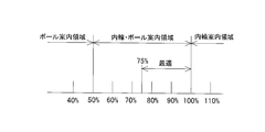
- the area where the ratio of the pocket clearance a to the guide clearance b of the inner ring 1 is 100% or more is an area where the pocket and the rolling element 3 do not contact.
- the ratio of the pocket clearance a to the guide clearance b of the inner ring 1 is 50% or less, as shown in FIG. 3, the cage 3 floats in the air, and the cage 3 serves as a rolling element guide.
- the region where the cage 3 is guided by the inner ring 1 and the pocket and the rolling element 4 are in contact with each other is a region where the ratio of the pocket clearance to the guide clearance of the inner ring is 50% to 100% or less.
- the force applied only to the cage 3 is distributed to the contact surfaces between the pockets and the rolling elements 4, thereby reducing the surface pressure of the cage 3 and the inner ring surface to reduce the guide surface of the cage 3. Can prevent wear.
- a material that easily wears such as ductile (spheroid graphite cast iron), can be used as the material of the cage 3.
- operation of the rolling bearing which concerns on this invention. It is a vertical side view of the rolling bearing of FIG. It is a front view which shows the relationship of the pocket clearance with respect to the guide clearance of the inner ring
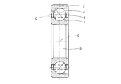
- FIG. 1 is a front view showing an angular ball bearing for a screw compressor.
- reference numeral 1 is an inner ring
- reference numeral 2 is an outer ring
- reference numeral 3 is a cage
- reference numeral 4 is a ball (rolling element)
- reference numeral 5 is a shaft
- reference numeral C is a PCD of the rolling element 4
- reference numeral O is a bearing (axis). Indicates the center of rotation.
- only the cage 3 is shown in cross section. The cage 3 is guided by the outer peripheral surface of the inner ring 2, and the ratio of the pocket clearance to the guide clearance of the inner ring 1 is set to an area of 75% to 100% or less.
- the cage 3 and the rolling element 1 come into contact with the inner ring 1 at the same time during operation.
- the surface pressure between the cage 3 and the inner ring surface is distributed by dispersing the force applied only to the cage 3 to the contact point A between the pocket of the cage 3 and the rolling element 4.
- ductile spheroidal graphite cast iron
Landscapes
- Engineering & Computer Science (AREA)
- General Engineering & Computer Science (AREA)
- Mechanical Engineering (AREA)
- Rolling Contact Bearings (AREA)
Abstract
スクリューコンプレッサー用アンギュラ玉軸受のように、保持器3の材質に、ダクタイル(球状黒鉛鋳鉄)のような摩耗しやすい材料を使用しても、案内面の摩耗を防止することができる保持器3を提供することを課題とする。運転中に内輪1に接触して案内される内輪案内型の転がり軸受の保持器3において、内輪1の案内すきまbに対するポケットすきまaの割合を、75%~100%以下の領域に設定することにより、ダクタイルのような磨耗しやすい材料を使用することができるようにした。
Description
この発明は、圧縮機油、冷凍機油、アンモニア冷媒等を使用するスクリューコンプレッサー用アンギュラ玉軸受の保持器に関するものである。
転がり軸受の保持器3は、図5に示すように、転動体4が互いに接触しないように等間隔に分離する働きと、転動体4が軌道輪(内輪1,外輪2)から脱落しないように保持する働きと、転動体4の回転を案内し、駆動する働きとを有している。
転がり軸受の保持器3には、転動体4との間にポケットすきまa、軌道輪との間に案内すきまbを有し、軸受の中で、これらのすきまが許容する範囲内で3次元的に自由に動けるように設計されている。
ところで、転がり軸受の保持器3には、軌道輪1,2の肩の部分との間の案内すきまの与え方によって、図7に示す転動体案内、図8に示す外輪案内、図9に示す内輪案内の3つの方式がある。
小型軸受では、保持器3の内径側と外径側のどちらにも内輪1、外輪2が接触しないように設計してあるので、保持器3は転動体4によってのみ回転の駆動と案内を受けるようにしている。これを転動体案内保持器と呼んでいる(図7)。
大型軸受では、保持器3の外径面を外輪2の肩部に接触させるか、保持器3の内径面と内輪1の肩部との間を積極的に接触させて、保持器3の回転を行っている。前者が外輪案内(図8)、後者が内輪案内(図9)の保持器3である。
内輪回転で外輪静止の普通の軸受の場合、転動体案内の保持器3では、図7に示すように、保持器3はポケット面の回転方向の側で、軸受の負荷帯の中にある転動体4と滑り接触し、その転動体4から駆動力を受けて回転する。
外輪案内の保持器でも、図8に示すように、同様に負荷帯の中にある転動体4から、回転のための駆動力Fを保持器ポケットの回転方向の側で受けて回転するが、保持器3は外輪案内面で発生する滑り摩擦力によって、回転に対するブレーキの作用を受ける。
これに対して、内輪案内の保持器3では、図9に示すように、内輪案内面と保持器3との接触面において、内輪案内面の周速は、公転速度で決まる保持器案内面の周速よりも常に大きくなる。したがって、保持器は内輪案内面において、その滑り摩擦力によって回転に対する駆動力Fを受ける。そのため、負荷帯の中の転動体4は、保持器ポケットの回転方向と反対側で接触しながら、保持器3の回転速度を規制することになる。
従来、案内すきまbを十分に確保しながら、回転中の軸受内で保持器3が径方向に移動したときに、軸受内で転動体が等間隔配置するようにできる保持器3を備えた転がり軸受が特許文献1に開示されている。
ところで、アンモニア冷媒を使用するスクリューコンプレッサー用アンギュラ玉軸受の保持器3は、通常、転動体4(ボール)又は軌道輪のいずれかに接触し、案内されながら回転している。
スクリューコンプレッサー用アンギュラ玉軸受は、潤滑油がアンモニア冷媒であり、保持器3の材質にダクタイル(球状黒鉛鋳鉄)を使用している。
一般的な保持器3の材質は、銅系材料の高力黄銅鋳物1種(CAC301)、鉄系材料の機械構造用炭素鋼(S30C)であり、このような一般的な材料と比較して、ダクタイル(球状黒鉛鋳鉄)は、摩耗しやすい特性がある。
したがって、保持器3の材質にダクタイル(球状黒鉛鋳鉄)を使用し、保持器3が内輪1によって案内される場合、潤滑油が案内面に供給される機構であっても、回転時の遠心力により潤滑油が外輪側に飛ばされるため、保持器3の案内面に潤滑油が供給されにくい場合が生じ、保持器3が摩耗する可能性がある。
特に、従来、スクリューコンプレッサー用アンギュラ玉軸受の保持器3の場合、案内すきまbに対するポケットすきまaの割合が100%以上の領域、即ち、ポケットすきまa>案内すきまbの関係に設定し、図3に示すように、保持器3と内輪1が接触しても、保持器3と転動体4とは接触せず、ポケットすきまaが設けられている。
したがって、従来のスクリューコンプレッサー用アンギュラ玉軸受では、保持器3の自重や回転時の遠心力が全て内輪1との案内面に掛かるため、案内部(接触部)の面圧が高くなり、潤滑油の供給されにくい場合には、保持器3が摩耗する可能性がある。
そこで、この発明は、スクリューコンプレッサー用アンギュラ玉軸受のように、保持器3の材質に、ダクタイル(球状黒鉛鋳鉄)のような摩耗しやすい材料を使用しても、案内面の摩耗を防止することができる保持器3を提供することを課題とするものである。
前記の課題を解決するために、この発明は、運転中に内輪1に接触して案内される内輪案内型の転がり軸受の保持器3において、内輪1の案内すきまbに対するポケットすきまaの割合を、75%~100%以下の領域に設定したことを特徴とする。
即ち、図10に示すように、内輪1の案内すきまbに対するポケットすきまaの割合が100%以上の領域とは、ポケットと転動体3とが接触しない領域である。また、内輪1の案内すきまbに対するポケットすきまaの割合が50%以下の場合、図3に示すように、保持器3が宙に浮いた状態となり、保持器3は転動体案内になる。
保持器3が内輪1に案内され、しかもポケットと転動体4とが接触する領域は、内輪の案内すきまに対するポケットすきまの割合が50%~100%以下の領域であるが、この発明は、内輪1の案内すきまbに対するポケットすきまaの割合を75%~100%以下にすることにより、保持器3が内輪1と接触するのと同時に、保持器3と転動体4とが接触する割合を増やし、保持器3だけに掛かっていた力を、ポケットと転動体4との接触面に分散させ、保持器3と内輪面の面圧を下げるようにしたものである。
この発明によれば、保持器3だけに掛かっていた力を、ポケットと転動体4との接触面に分散させることにより、保持器3と内輪面の面圧を下げて保持器3の案内面の摩耗を防止することができる。
したがって、この発明によれば、保持器3の材質に、ダクタイル(球状黒鉛鋳鉄)のような摩耗しやすい材料を使用することができる。
以下、この発明の実施の形態を添付図面に基づいて説明する。
図1は、スクリューコンプレッサー用アンギュラ玉軸受を示す正面図である。
この図において、符号1は内輪、符号2は外輪、符号3は保持器、符号4は玉(転動体)、符号5は軸、符号Cは転動体4のPCD、符号Oは軸受(軸)の回転中心を示す。なお、この図において、保持器3だけは断面で示してある。この保持器3は内輪2の外周面で案内され、内輪1の案内すきまに対するポケットすきまの割合を、75%~100%以下の領域に設定している。
図1は、スクリューコンプレッサー用アンギュラ玉軸受を示す正面図である。
この図において、符号1は内輪、符号2は外輪、符号3は保持器、符号4は玉(転動体)、符号5は軸、符号Cは転動体4のPCD、符号Oは軸受(軸)の回転中心を示す。なお、この図において、保持器3だけは断面で示してある。この保持器3は内輪2の外周面で案内され、内輪1の案内すきまに対するポケットすきまの割合を、75%~100%以下の領域に設定している。
内輪1の案内すきまに対するポケットすきまの割合を、75%~100%以下の領域に設定することにより、運転中に、保持器3が内輪1と接触するのと同時に、保持器3と転動体1との接触点Aを有し、保持器3だけに掛かっていた力を、保持器3のポケットと転動体4との接触点Aに分散させることにより、保持器3と内輪面の面圧を下げて保持器3の案内面の摩耗を防止している。
この実施形態では、保持器3の材質に、ダクタイル(球状黒鉛鋳鉄)を使用している。
1 内輪
2 外輪
3 保持器
4 転動体
5 軸
a ポケットすきま
b 案内すきま
A 接触点
2 外輪
3 保持器
4 転動体
5 軸
a ポケットすきま
b 案内すきま
A 接触点
Claims (3)
- 運転中に内輪に接触して案内される内輪案内型の転がり軸受の保持器において、内輪の案内すきまに対するポケットすきまの割合を、75%~100%以下の領域に設定したことを特徴とする転がり軸受の保持器。
- 保持器材料をダクタイルとしたことを特徴とする転がり軸受の保持器。
- 請求項1又は2の保持器を使用するスクリューコンプレッサー用アンギュラ玉軸受。
Priority Applications (3)
| Application Number | Priority Date | Filing Date | Title |
|---|---|---|---|
| US14/786,282 US20160076589A1 (en) | 2013-04-25 | 2014-04-21 | Cage for rolling bearing |
| CN201480023274.0A CN105143695A (zh) | 2013-04-25 | 2014-04-21 | 滚动轴承的保持架 |
| EP14787535.5A EP2990670A4 (en) | 2013-04-25 | 2014-04-21 | CAGE FOR BEARING |
Applications Claiming Priority (2)
| Application Number | Priority Date | Filing Date | Title |
|---|---|---|---|
| JP2013092124A JP2014214792A (ja) | 2013-04-25 | 2013-04-25 | 転がり軸受の保持器 |
| JP2013-092124 | 2013-04-25 |
Publications (1)
| Publication Number | Publication Date |
|---|---|
| WO2014175210A1 true WO2014175210A1 (ja) | 2014-10-30 |
Family
ID=51791786
Family Applications (1)
| Application Number | Title | Priority Date | Filing Date |
|---|---|---|---|
| PCT/JP2014/061157 Ceased WO2014175210A1 (ja) | 2013-04-25 | 2014-04-21 | 転がり軸受の保持器 |
Country Status (5)
| Country | Link |
|---|---|
| US (1) | US20160076589A1 (ja) |
| EP (1) | EP2990670A4 (ja) |
| JP (1) | JP2014214792A (ja) |
| CN (1) | CN105143695A (ja) |
| WO (1) | WO2014175210A1 (ja) |
Families Citing this family (4)
| Publication number | Priority date | Publication date | Assignee | Title |
|---|---|---|---|---|
| CN106438687A (zh) * | 2016-12-09 | 2017-02-22 | 瓦房店轴承集团有限责任公司 | 太阳能晶硅切片机用配对角接触球轴承 |
| DE102017112362A1 (de) * | 2017-06-06 | 2018-12-06 | Schaeffler Technologies AG & Co. KG | Verfahren zur Herstellung eines Käfigs für Wälzlager |
| DE102018101551A1 (de) * | 2018-01-24 | 2018-12-13 | Schaeffler Technologies AG & Co. KG | Käfig für ein Wälzlager, Verfahren zum Fertigen des Käfigs sowie ein Käfigrohling |
| CN111765171A (zh) * | 2020-07-16 | 2020-10-13 | 河南科技大学 | 一种圆柱滚子轴承及其保持架 |
Citations (4)
| Publication number | Priority date | Publication date | Assignee | Title |
|---|---|---|---|---|
| JP2000346079A (ja) | 1999-06-03 | 2000-12-12 | Nsk Ltd | 転がり軸受 |
| JP2004301314A (ja) * | 2003-04-01 | 2004-10-28 | Nsk Ltd | 転がり軸受 |
| JP2012031904A (ja) * | 2010-07-29 | 2012-02-16 | Nsk Ltd | ころ軸受用保持器 |
| JP2012149702A (ja) * | 2011-01-19 | 2012-08-09 | Nsk Ltd | 転がり軸受 |
Family Cites Families (4)
| Publication number | Priority date | Publication date | Assignee | Title |
|---|---|---|---|---|
| JP2584936Y2 (ja) * | 1992-08-19 | 1998-11-11 | 日本精工株式会社 | ターボチャージャー用玉軸受 |
| DE10165027C5 (de) * | 2000-10-27 | 2019-10-02 | Nsk Ltd. | Wälzlager und Spindelvorrichtung für Werkzeugmaschine |
| JP4326159B2 (ja) * | 2001-02-09 | 2009-09-02 | 株式会社ジェイテクト | 玉軸受 |
| JP2002333027A (ja) * | 2001-05-09 | 2002-11-22 | Ntn Corp | 超薄肉形転がり軸受 |
-
2013
- 2013-04-25 JP JP2013092124A patent/JP2014214792A/ja active Pending
-
2014
- 2014-04-21 US US14/786,282 patent/US20160076589A1/en not_active Abandoned
- 2014-04-21 EP EP14787535.5A patent/EP2990670A4/en not_active Withdrawn
- 2014-04-21 WO PCT/JP2014/061157 patent/WO2014175210A1/ja not_active Ceased
- 2014-04-21 CN CN201480023274.0A patent/CN105143695A/zh active Pending
Patent Citations (4)
| Publication number | Priority date | Publication date | Assignee | Title |
|---|---|---|---|---|
| JP2000346079A (ja) | 1999-06-03 | 2000-12-12 | Nsk Ltd | 転がり軸受 |
| JP2004301314A (ja) * | 2003-04-01 | 2004-10-28 | Nsk Ltd | 転がり軸受 |
| JP2012031904A (ja) * | 2010-07-29 | 2012-02-16 | Nsk Ltd | ころ軸受用保持器 |
| JP2012149702A (ja) * | 2011-01-19 | 2012-08-09 | Nsk Ltd | 転がり軸受 |
Non-Patent Citations (1)
| Title |
|---|
| See also references of EP2990670A4 |
Also Published As
| Publication number | Publication date |
|---|---|
| JP2014214792A (ja) | 2014-11-17 |
| CN105143695A (zh) | 2015-12-09 |
| EP2990670A1 (en) | 2016-03-02 |
| US20160076589A1 (en) | 2016-03-17 |
| EP2990670A4 (en) | 2016-11-09 |
Similar Documents
| Publication | Publication Date | Title |
|---|---|---|
| WO2009150935A1 (ja) | 保持器、深溝玉軸受、およびシール付軸受 | |
| JP2008240796A (ja) | シール付きアンギュラ玉軸受及び主軸装置 | |
| JP2015224793A (ja) | 新規の円錐ころ軸受および当該軸受を用いた新規のシャフトシステム | |
| WO2014175210A1 (ja) | 転がり軸受の保持器 | |
| JP2015086940A (ja) | 転がり軸受 | |
| JP2009068592A (ja) | 保持器付自動調心ころ軸受及び自動調心ころ軸受用保持器の製造方法 | |
| CN106536951B (zh) | 用于涡轮增压器的球轴承 | |
| CA2498748A1 (en) | Bearing with pass or fail wear gauge | |
| US20110135235A1 (en) | Ball bearing for a turbocharger | |
| JPWO2006057258A1 (ja) | 保持器付自動調心ころ軸受及び自動調心ころ軸受用保持器の製造方法 | |
| JP2009275722A (ja) | 転がり軸受 | |
| JP2009024807A (ja) | 密封装置 | |
| JP2015117804A (ja) | アンギュラ玉軸受 | |
| JP2007177858A (ja) | 玉軸受および玉軸受アセンブリ | |
| JP2006266277A (ja) | 保持器付自動調心ころ軸受 | |
| JP5926061B2 (ja) | 密封型転がり軸受 | |
| JP2007298184A (ja) | アンギュラ玉軸受 | |
| CN205744934U (zh) | 一种工业抗磨损轴承内圈 | |
| JP5985684B2 (ja) | スラスト軸受及びその保持器 | |
| CN202926880U (zh) | 滚动轴承 | |
| JP5120703B2 (ja) | スラストころ軸受 | |
| CN110552957B (zh) | 一种高速轴承 | |
| JP2007127251A (ja) | 複列自動調心ころ軸受 | |
| JP2015218786A (ja) | アンギュラ玉軸受 | |
| JP5919690B2 (ja) | 車両車軸用軸受装置 |
Legal Events
| Date | Code | Title | Description |
|---|---|---|---|
| WWE | Wipo information: entry into national phase |
Ref document number: 201480023274.0 Country of ref document: CN |
|
| 121 | Ep: the epo has been informed by wipo that ep was designated in this application |
Ref document number: 14787535 Country of ref document: EP Kind code of ref document: A1 |
|
| WWE | Wipo information: entry into national phase |
Ref document number: 14786282 Country of ref document: US |
|
| NENP | Non-entry into the national phase |
Ref country code: DE |
|
| WWE | Wipo information: entry into national phase |
Ref document number: 2014787535 Country of ref document: EP |