WO2014175283A1 - 放射線測定装置 - Google Patents
放射線測定装置 Download PDFInfo
- Publication number
- WO2014175283A1 WO2014175283A1 PCT/JP2014/061327 JP2014061327W WO2014175283A1 WO 2014175283 A1 WO2014175283 A1 WO 2014175283A1 JP 2014061327 W JP2014061327 W JP 2014061327W WO 2014175283 A1 WO2014175283 A1 WO 2014175283A1
- Authority
- WO
- WIPO (PCT)
- Prior art keywords
- pulse
- signal
- circuit
- discrimination
- bipolar
- Prior art date
- Legal status (The legal status is an assumption and is not a legal conclusion. Google has not performed a legal analysis and makes no representation as to the accuracy of the status listed.)
- Ceased
Links
Images



Classifications
-
- G—PHYSICS
- G01—MEASURING; TESTING
- G01T—MEASUREMENT OF NUCLEAR OR X-RADIATION
- G01T1/00—Measuring X-radiation, gamma radiation, corpuscular radiation, or cosmic radiation
- G01T1/16—Measuring radiation intensity
- G01T1/17—Circuit arrangements not adapted to a particular type of detector
-
- G—PHYSICS
- G01—MEASURING; TESTING
- G01T—MEASUREMENT OF NUCLEAR OR X-RADIATION
- G01T1/00—Measuring X-radiation, gamma radiation, corpuscular radiation, or cosmic radiation
-
- G—PHYSICS
- G01—MEASURING; TESTING
- G01T—MEASUREMENT OF NUCLEAR OR X-RADIATION
- G01T1/00—Measuring X-radiation, gamma radiation, corpuscular radiation, or cosmic radiation
- G01T1/16—Measuring radiation intensity
- G01T1/161—Applications in the field of nuclear medicine, e.g. in vivo counting
-
- G—PHYSICS
- G01—MEASURING; TESTING
- G01T—MEASUREMENT OF NUCLEAR OR X-RADIATION
- G01T1/00—Measuring X-radiation, gamma radiation, corpuscular radiation, or cosmic radiation
- G01T1/16—Measuring radiation intensity
- G01T1/161—Applications in the field of nuclear medicine, e.g. in vivo counting
- G01T1/164—Scintigraphy
-
- G—PHYSICS
- G01—MEASURING; TESTING
- G01T—MEASUREMENT OF NUCLEAR OR X-RADIATION
- G01T1/00—Measuring X-radiation, gamma radiation, corpuscular radiation, or cosmic radiation
- G01T1/36—Measuring spectral distribution of X-rays or of nuclear radiation spectrometry
Definitions
- the present invention relates to a radiation measuring apparatus, and more particularly to a radiation measuring apparatus that distinguishes and detects ⁇ rays and ⁇ rays.
- Patent Documents 1 and 2 disclose a radiation measurement apparatus having an ⁇ -ray separation filter and a peak value discrimination circuit.
- noise is cut by coincidence processing for pulses output from two photomultiplier tubes, and then an ⁇ -ray detection pulse and a ⁇ -ray detection pulse are based on the pulse width of the pulse after the coincidence processing.
- a radiation measurement device for distinguishing between the two is disclosed.
- a detection pulse output from a detector constituted by a scintillator and a photomultiplier tube is a unipolar pulse that appears on the negative electrode side (or positive electrode side).
- the unipolar pulse usually has a steep rising part from the rising point to the peak point (also called leading edge) and a relatively gentle falling part from the peak point to the baseline (also called trailing edge).
- the pulse width of such a detection pulse depends on the line type. In general, the pulse width of the ⁇ -ray detection pulse is larger than the pulse width of the ⁇ -ray detection pulse. Therefore, the pulse width can be used as a reference for line type discrimination.
- the waveform of the detection pulse is compared with a threshold level, a rising point and a falling point are specified as points that cross the threshold level, and a pulse width is specified between them.
- the amplitude change away from the baseline is referred to as “rising”, and the amplitude change approaching the baseline is referred to as “falling”.
- the “rising point” is generally a start point or a front end point (including points corresponding thereto) in a slope existing immediately before the peak point, and the “falling point” generally exists immediately after the peak point. It is an end point or a rear end point (including points corresponding to them) in the slope.
- the accuracy of pulse width will affect the discrimination accuracy of line type, so it is necessary to configure the circuit so that the pulse width can be specified as accurately as possible.
- the falling part of the detection pulse has a gentle shape, particularly near the base line, the point crossing the threshold level tends to fluctuate in the time axis direction due to subtle fluctuations in the shape of that part. There's a problem.
- the pulse peak value is used as the discrimination standard. This is because the pulse width of the detection pulse depends on the peak value, and especially when the amplitude is small, the error tends to increase. In line type discrimination, noise superposition, signal saturation after amplification, influence of proximity pulses, and the like can be considered. Generally, the range where the peak value of the ⁇ -ray detection pulse can take and the range where the peak value of the ⁇ -ray detection pulse can partially overlap, so the It is difficult to discriminate. Therefore, it is desirable to discriminate line types based on both the crest value criterion and the pulse width criterion.
- An object of the present invention is to increase the discrimination accuracy between an ⁇ ray detection pulse and a ⁇ ray detection pulse.
- the object is to eliminate or alleviate the problem of a decrease in discrimination accuracy due to a variation in the shape of the falling portion of the detection pulse.
- a radiation measurement apparatus includes a detector that detects ⁇ rays and ⁇ rays and outputs a unipolar pulse, and a preprocessing that generates a bipolar pulse by waveform processing of the unipolar pulse output from the detector.
- a line type discrimination circuit that performs line type discrimination.
- the characteristic accuracy of the pulse width can be improved.
- the first falling part is steeper near the baseline compared to the unipolar pulse, and unlike the unipolar pulse, the falling part penetrates the baseline. Increases the accuracy of point identification.
- the falling point can be specified as a point where the falling portion crosses a predetermined threshold. In this case, if the predetermined threshold is the baseline, the falling point is defined as a cross point that crosses the baseline. It is easy to specify the cross point.
- the base line may be at a level offset from the level of potential 0, and even in that case, a point crossing the base line can be referred to as a cross point. It is also possible to specify the rising point as a point away from the base line or as a point crossing the base line.
- the levels for specifying the rising point and the falling point are not necessarily the same, that is, the pulse width signal generation circuit may have a hysteresis characteristic.
- the preprocessing circuit a differential circuit and an integration circuit connected in series may be provided. In any case, generation of a bipolar pulse from a unipolar pulse is a feature of the above configuration.
- the bipolar pulse includes a first part protruding from the baseline to one side and a second part following the first part and protruding from the baseline to the other side,
- the rising point is the front end point of the first part
- the falling point is the rear end point of the first part.
- the detector includes one or more photomultiplier tubes. It is particularly desirable to have a single photomultiplier tube. It is desirable that the ⁇ ray detection and the ⁇ ray detection can be comprehensively discriminated only from the output signal of such a single photomultiplier tube.
- the pulse width signal generation circuit includes a reference signal generation circuit that generates a reference signal by smoothing the bipolar pulse, and the rising point and the reference signal by comparing the bipolar pulse with the reference signal. And a comparison circuit for specifying the cross point.
- the reference signal generated from the bipolar pulse itself is used.
- the reference signal is generated by smoothing the bipolar pulse, which corresponds to the baseline of the bipolar pulse. Therefore, even if a shift occurs in the base line of the bipolar pulse, the reference signal is also shifted in the same manner, so that a comparison process that is not affected by such a shift can be realized.
- the line type discrimination circuit performs the line type discrimination based on the peak value of the bipolar pulse and the peak value of the unipolar pulse in addition to the pulse width of the bipolar pulse. According to this configuration, since discrimination can be performed from multiple sides or comprehensively, discrimination accuracy can be improved. In particular, if a unipolar pulse that is a source for generating a bipolar pulse is evaluated, nuclide discrimination can be performed in consideration of the evaluation result of a signal that is not affected by preprocessing.
- it includes a large pulse detection signal generation circuit that generates a large pulse detection signal indicating that the unipolar pulse is a large pulse higher than a large pulse discrimination level, and outputs the large pulse detection signal to the line type discrimination circuit, If the large pulse discrimination level is exceeded, it can be regarded as ⁇ -ray detection.
- an effective pulse discrimination signal generation circuit that generates an effective pulse determination signal indicating that the bipolar pulse is an effective pulse larger than a noise cut level, and outputs the effective pulse determination signal to the line type determination circuit, and the noise
- the cut level is a level for discriminating noise from effective pulses.
- the line type discrimination circuit includes a high level discrimination signal generating circuit that generates a high level discrimination signal indicating whether the bipolar pulse is higher or lower than an intermediate level and outputs the high level discrimination signal to the line type discrimination circuit, This is a level for discriminating between a high peak value that can occur in the case of detection and ⁇ -ray detection and a low peak value that can occur only in the case of ⁇ detection.
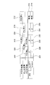
- FIG. 1 shows a preferred embodiment of a radiation measuring apparatus according to the present invention
- FIG. 1 is a circuit diagram thereof.
- the radiation measuring apparatus in this embodiment is a survey meter, for example.
- the radiation measuring apparatus shown in FIG. 1 has a scintillator and a photomultiplier tube as detectors.
- the scintillator emits light by the incidence of ⁇ rays and ⁇ rays. As that light enters the photomultiplier tube, it is converted into electrical pulses.
- only a single photomultiplier tube is provided.
- the output pulse 100 is a unipolar pulse generated on the negative direction side in the present embodiment.
- a plurality of photomultiplier tubes may be provided.
- the radiation measuring apparatus includes a first amplifier 12, a second amplifier 14, a pulse width signal generation circuit 16, an effective pulse discrimination signal generation circuit 18, a large pulse inversion signal generation circuit 20, and a high level discrimination signal generation circuit 22.
- the determination circuit 24 and the microcomputer 26 are provided. Hereinafter, each circuit will be described in detail.
- the output pulse 100 from the photomultiplier tube is input to the first amplifier 12.
- the output pulse 100 has a form protruding from the base line to the negative polarity side.
- a capacitor C1 and a resistor R1 are provided on the input side of the first amplifier 12.
- the first amplifier 12 is a circuit that performs inverting amplification, and includes an operational amplifier 28 having an inverting amplification function.
- the output pulse 100 is input to the negative terminal of the operational amplifier 28, and the reference signal (REF 1) is input to the positive terminal of the operational amplifier 28.
- the reference signal is a signal representing a reference potential.
- the operational characteristics of the operational amplifier 28 are set by an RC circuit, and the RC circuit is composed of a resistor R2 and a capacitor C2.
- the first amplifier 12 outputs an inverted and amplified signal 102.
- the signal 102 is input to the second amplifier 14.
- the second amplifier 14 is a circuit that executes preprocessing for converting the signal 102, which is a unipolar pulse, into a bipolar pulse (bipolar signal).
- the second amplifier 14 has a differentiation circuit 14A and an integration circuit 14B connected in series.
- the differentiating circuit 14A includes two capacitors C3 and C4 provided in parallel and resistors R3 and R4 provided in parallel as well.
- the integrating circuit 14B has an operational amplifier 30.
- the output signal from the differentiation circuit 14A is given to the negative terminal of the operational amplifier 30, and the reference signal (REF2) is given to the positive terminal of the operational amplifier 30.
- the reference signal is a signal representing a reference potential.
- the operational characteristics of the operational amplifier 30 are determined by an RC circuit, which is specifically composed of a resistor R5 and a capacitor C5.
- a protection circuit is provided in front of the first amplifier 12, but the protection circuit is not shown in FIG.
- the potential of each reference signal can be variably set by a control circuit.
- the control circuit is not shown.
- a bipolar pulse that is, a bipolar signal is generated from a unipolar pulse, and the bipolar signal is denoted by reference numeral 104 in FIG.
- the bipolar signal 104 is output in parallel to a pulse width signal generation circuit 16, an effective pulse discrimination signal generation circuit 18, and a high level discrimination signal generation circuit 22 provided at the subsequent stage of the second amplifier 14.
- the output signal 102 of the first amplifier 12 is output to the second amplifier 14 and is also output to the large pulse determination signal generation circuit 20 without passing through it.
- the pulse width signal generation circuit 16 generates a pulse width signal P (W) based on the bipolar signal 104.
- the pulse width signal generation circuit 16 includes an operational amplifier 32, which functions as a comparator.
- the bipolar signal 104 is input to the + terminal 106 of the operational amplifier 32 via the resistor R6. It can be said that the signal is the attention signal 106.
- a reference signal 108 is input to the negative terminal of the operational amplifier 32.
- the reference signal 108 is generated based on the bipolar signal 104 itself, that is, the reference signal 108 is generated by applying a smoothing process to the bipolar signal 104.
- the pulse width signal P (W) can be generated without being affected by the fluctuation.
- a resistor R7 and a capacitor C6 are provided for smoothing the bipolar signal 104.
- the resistor R8 is for determining the potential.
- the resistor R9 as a feedback resistor is for slightly raising the level of the signal of interest 106 from the base line to the positive electrode side to give an offset to the signal of interest 106. By applying such shift processing, it is possible to reliably detect the rising point in the signal of interest 106. In the present embodiment, the zero cross point with the baseline is detected as the rising point. That is, the pulse width signal generation circuit 16 has a hysteresis characteristic.
- the output signal 110 from the pulse width signal generation circuit 16 is output to the determination circuit 24 as a pulse width signal P (W) via the resistor R10.
- the pulse width signal P (W) is a signal representing a period (pulse width) from the first rising point in the bipolar signal 104 to the subsequent zero cross point, as will be described in detail later.
- the effective pulse discrimination signal generation circuit 18 has an operational amplifier 34 that functions as a comparator.
- a bipolar signal 104 is given to the + terminal as a signal of interest 112 via a resistor R11.
- a resistor R13 is provided between the output side of the resistor R11 and the ground.
- R14 is a feedback resistor.
- the reference signal 114 is input to the negative terminal of the operational amplifier 34.
- the reference signal 114 is generated based on the bipolar signal 104 itself. That is, the reference signal is generated by smoothing the bipolar signal.
- a resistor R12 and a capacitor C7 are provided for smoothing. According to such a configuration, even if the baseline level in the bipolar signal 104 varies as described above, the signal comparison processing can be performed without being affected by the fluctuation.
- a control signal 116 is given to the input line to the-terminal. With the control signal 116, the potential of the reference signal 114 can be controlled from the outside. This makes it possible to variably set the noise cut level.
- Resistors R15 and R16 and a capacitor C8 are provided for potential operation by the control signal 116.
- the effective pulse discrimination signal generation circuit 18 discriminates a pulse exceeding the noise cut level as an effective pulse, and outputs an effective pulse discrimination signal P (D) representing it. Specifically, the output signal 118 of the operational amplifier 34 is sent to the determination circuit 24 as an effective pulse discrimination signal P (D) via the resistor R17.
- the high level discrimination signal generation circuit 22 is a circuit that generates a high level discrimination signal P (A) indicating that the effective pulse has a high peak value.
- the high level discrimination signal generation circuit 22 includes an operational amplifier 38, which functions as a comparator.
- the bipolar signal 104 is input to the + terminal of the operational amplifier 38 via the resistor R20, and the reference signal (REF4) is applied to the ⁇ terminal of the operational amplifier 38.
- the reference signal gives a reference potential.
- the reference potential represents an intermediate level for discriminating the peak value of the peak.
- the high level discrimination signal P (A) is output.
- the output signal 122 of the operational amplifier 38 is output to the determination circuit 24 as the high level discrimination signal P (A) via the resistor R21.
- the large pulse determination signal generation circuit 20 is a circuit that evaluates the output signal of the first amplifier 12. That is, by referring to the signal 102 before the preprocessing is performed in the second amplifier 14, a more faithful determination is performed in relation to the original pulse waveform. As a result, even when saturation occurs in the second amplifier 14, it is possible to evaluate the signal before saturation.
- the large pulse determination signal generation circuit 20 includes an operational amplifier 36 that functions as a comparator, and the output signal 102 of the first amplifier 12 is input to the + terminal thereof via a resistor R18.
- the output signal 102 is a unipolar pulse generated on the positive electrode side.
- a reference signal (REF3) is applied to the negative terminal of the operational amplifier 36. It indicates the potential for determining the large pulse.
- the operational amplifier 36 outputs a large pulse determination signal P (L) when a pulse higher than the potential is input. Specifically, the output signal 120 of the operational amplifier 36 is output to the determination circuit 24 as a large pulse determination signal P (L) via the resistor R19.
- the determination circuit 24 is multifaceted based on the input pulse width signal P (W), effective pulse discrimination signal P (D), large pulse determination signal P (L), and high level discrimination signal P (A). Alternatively, it is a circuit that comprehensively discriminates line types.
- a detection pulse 124 is output when ⁇ -ray detection is determined, and a ⁇ detection pulse 126 is output when ⁇ -ray detection is determined.
- the microcomputer 26 individually counts such pulses 124 and 126, thereby obtaining the ⁇ -ray count result and the ⁇ -ray count result independently. Based on these, various measurement values such as a dose, a dose rate, and a dose equivalent are calculated. Such a calculation result is displayed on a display.
- the microcomputer 26 controls the potential of the control signal 116 described above.
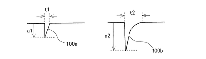
- FIG. 2 shows the unipolar pulse described above.
- This is the output pulse of the photomultiplier tube.
- (A) shows a ⁇ -ray detection pulse 100a generated by detecting ⁇ -rays
- (B) shows an ⁇ -ray detection pulse 100b generated by detecting ⁇ -rays.
- a1 indicates the pulse peak value (height from the base line to the peak point)
- t1 indicates the pulse width (range on the time axis).
- a2 indicates the pulse peak value
- t2 indicates the pulse width.
- the problem is the pulse widths t1 and t2.
- the falling waveform portion becomes gentler as it approaches the baseline, and it is difficult to specify the pulse width accurately.
- a unipolar pulse is converted into a bipolar signal as shown in FIG. 3 in order to specify the pulse width more accurately.
- the bipolar signal is a bipolar pulse generated from a unipolar pulse, and in the configuration shown in FIG. 1, the differential signal and the integral process are performed stepwise on the output signal of the first amplifier 12 to obtain the bipolar signal.
- a bipolar signal 104 is generated.
- Bipolar signal 104 has a mountain-shaped first portion protruding from the base line to one side (negative electrode side) and a mountain-shaped second portion protruding from the base line to the other side (positive electrode side). .
- a second part occurs immediately after the first part, and both are connected.
- the first rising portion (slope as leading edge) existing immediately before the first peak point is quite steep, and the first rising point 204 can be clearly identified.
- the first rising point corresponds to the start point or the front end point of the rising portion (or the first portion).
- a falling portion (slope as a trailing edge) existing immediately after the first peak point is steeper than a falling portion in a unipolar pulse, and it crosses the baseline. Therefore, the falling point or zero cross point 206 can be clearly specified.
- the falling point corresponds to the end point or the rear end point of the falling portion (or the first portion).
- the pulse width t can be specified with high accuracy based on the bipolar signal. Thereby, the discrimination accuracy of alpha ray detection and beta ray detection can be improved.
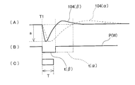
- FIG. 4 shows the operation of the pulse width signal generation circuit shown in FIG. (A) shows an input bipolar signal.
- reference numeral 104 ( ⁇ ) represents a bipolar signal generated by detection of ⁇ rays
- reference numeral 104 ( ⁇ ) represents a bipolar signal generated by detection of ⁇ rays.
- the level of both peak points is indicated by a.
- (B) shows a pulse width signal P (W).
- t ( ⁇ ) represents a pulse width in the bipolar signal 104 ( ⁇ ) generated by detection of ⁇ rays
- t ( ⁇ ) represents a pulse width in the bipolar signal 104 ( ⁇ ) generated by detection of ⁇ rays. Is shown.
- (C) shows the judgment gate period. It is determined as a period of, for example, 0.5 s from the timing T1 of the rising point, and within the determination gate period, the effective pulse discrimination signal P (D), the large pulse determination signal P (L), and the high level discrimination signal It is determined whether or not P (A) has occurred.
- FIG. 5 shows various discrimination levels compared with the waveform.
- (A) shows the output signal of the first amplifier shown in FIG.
- the horizontal axis is the time axis, and the vertical axis represents the amplitude.
- Reference numeral 208 denotes a baseline.
- a5 indicates a large pulse discrimination level. This corresponds to REF3 described above.
- the large pulse determination signal P (L) described above is output.
- (B) shows the bipolar signal described above.
- the vertical axis represents the amplitude, and the horizontal axis is the time axis.
- Reference numeral 208 denotes a baseline.
- a3 is a noise cut level, which corresponds to the signal 114 shown in FIG. a4 indicates an intermediate level, which corresponds to REF4 described above.
- a signal exceeding the noise cut level a3 is regarded as an effective pulse.
- an intermediate level a4 is determined.
- the peak value a exceeds the intermediate level a4
- the possibility of ⁇ -ray detection and ⁇ -ray detection is recognized, and a high-level discrimination signal P (A) representing this is output. If the peak value a does not exceed the intermediate level a4, the signal is regarded as a ⁇ -ray detection pulse.
- FIG. 6 shows an example of a determination rule in the determination circuit shown in FIG.
- the determination circuit first, the presence or absence of P (D) is determined. As indicated by reference numeral 212, when P (D) is not obtained, the signal is regarded as noise regardless of the contents of other signals as indicated by reference numerals 214 and 216. That is, neither ⁇ -ray detection nor ⁇ -ray detection is determined. On the other hand, as indicated by reference numeral 210, when P (D) is obtained, the determination result may vary depending on the contents of other signals.
- ⁇ -ray detection is determined as indicated by reference numeral 224. That is, since the peak value of the pulse is small, ⁇ -ray detection cannot be considered, and in the case of ⁇ -ray detection, the pulse width should always be smaller than 1 ⁇ s, so ⁇ -ray detection is determined. In such a case, if the pulse width is 1 ⁇ s or more, it is an error as indicated by reference numeral 226.
- determination is first made on the assumption that there is an effective signal equal to or higher than the noise cut level.
- the output signal of the first amplifier before being processed by the second amplifier is determined. If the size is huge, ⁇ -ray detection is unconditionally determined. Otherwise, the comparison result with the intermediate level and the pulse width are comprehensively considered, and ⁇ -ray detection or ⁇ -ray detection is performed. Has been determined. Therefore, there is an advantage that the line type can be accurately determined according to various situations.
- the pulse width is measured after converting a unipolar pulse into a bipolar signal, so that an error can be reduced particularly in specifying the falling point of the pulse, that is, the specifying accuracy can be improved.
- the crossing point between the falling part and the baseline is regarded as the zero cross point, but it is also possible to set a level shifted from the base line and specify the falling point as a point crossing the level.
- the rising point can be specified by comparing the rising point with a threshold having a certain offset from the baseline.
- Bipolar signals are generally usable not only in the above-described determination circuit but also in pulse width evaluation.
- the reference signal is generated based on the bipolar signal itself when generating the pulse width signal, there is an advantage that it is not easily affected by the baseline level fluctuation in the bipolar signal. This also applies to the generation of the reference signal in the effective pulse discrimination signal generation circuit.
Landscapes
- Physics & Mathematics (AREA)
- Health & Medical Sciences (AREA)
- Spectroscopy & Molecular Physics (AREA)
- General Physics & Mathematics (AREA)
- High Energy & Nuclear Physics (AREA)
- Molecular Biology (AREA)
- Life Sciences & Earth Sciences (AREA)
- Engineering & Computer Science (AREA)
- Biomedical Technology (AREA)
- General Health & Medical Sciences (AREA)
- Medical Informatics (AREA)
- Nuclear Medicine, Radiotherapy & Molecular Imaging (AREA)
- Optics & Photonics (AREA)
- Measurement Of Radiation (AREA)
Abstract
光電子増倍管から出力された単極性パルスに対して前処理が施され、これによってバイポーラ信号(両極性パルス)が生成される。バイポーラ信号において、最初のピーク波形における立ち下がり波形部分(後側スロープ)は、急峻であり、またベースラインを横切ることになるから、立ち下がり点をゼロクロス点として精度良く特定することが可能である。これによってパルス幅tの特定精度を向上できる。線種判別にあたっては、上記パルス幅の他に、単極性パルスの波高値、バイポーラ信号の波高値、等がさらに参照されてもよい。
Description
本発明は放射線測定装置に関し、特に、α線及びβ線を区別して検出する放射線測定装置に関する。
α線及びβ線を測定する放射線測定装置においては、α線検出により生じた検出パルス(α線検出パルス)とβ線検出により生じた検出パルス(β線検出パルス)との間における周波数特性及び波高値の相違を利用して、検出器から出力されるα線検出パルス及びβ線検出パルスを区別している。例えば、特許文献1、2には、α線分離フィルタ及び波高値弁別回路を有する放射線測定装置が開示されている。特許文献3には、2つの光電子増倍管から出力されたパルスに対する同時計数処理によりノイズをカットした上で、同時計数処理後のパルスのパルス幅に基づいてα線検出パルス及びβ線検出パルスを区別する放射線測定装置が開示されている。
例えば、シンチレータ及び光電子増倍管により構成される検出器から出力される検出パルスは、負極側(または正極側)に現れる単極性パルスである。その単極性パルスは、通常、立ち上がり点からピーク点までの急峻な立ち上がり部分(leading edgeとも言う)と、ピーク点からベースラインまでに達する比較的なだらかな立ち下がり部分(trailing edgeとも言う)と、を含む。そのような検出パルスのパルス幅(例えばベースライン付近の時間幅)は線種に依存する。一般に、α線検出パルスのパルス幅はβ線検出パルスのパルス幅よりも大きい。よって、パルス幅を線種弁別の基準とすることが可能である。例えば、検出パルスの波形が閾値レベルと比較され、閾値レベルを横切る点として立ち上がり点及び立ち下がり点が特定され、それらの間がパルス幅として特定される。なお、本願明細書では、極性にかかわらず、ベースラインから離れる振幅変化を「立ち上がり」と称し、ベースラインに近付く振幅変化を「立ち下がり」と称する。「立ち上がり点」は、一般に、ピーク点の直前に存在するスロープにおける開始点又は前端点(それらに相当する点を含む)であり、「立ち下がり点」は、一般に、ピーク点の直後に存在するスロープにおける終了点又は後端点(それらに相当する点を含む)である。
核種弁別においてパルス幅を利用する場合、パルス幅の特定精度が線種の弁別精度を左右することになるから、できる限りパルス幅を正確に特定できるように回路を構成する必要がある。しかし、検出パルスにおける立ち下がり部分においては、特にベースライン付近で、なだらかな形状となっているため、その部分の形状の微妙な変動によって、閾値レベルを横切る点が時間軸方向に変動し易いという問題がある。
なお、弁別精度の観点から、パルス幅を弁別基準とすることに加えて、パルス波高値も弁別基準とするのが望ましい。検出パルスのパルス幅は波高値に依存し、特に小振幅の場合に誤差が大きくなる傾向が認められるからである。線種判別に当たっては、ノイズ重畳、増幅後の信号飽和、近接パルスの影響等も考えられる。一般に、α線検出パルスの波高値がとり得る範囲と、β線検出パルスの波高値がとり得る範囲は、部分的にオーバーラップするので、波高値だけからα線検出パルスとβ線検出パルスを弁別するのは難しい。よって、波高値基準とパルス幅基準の両基準をもって線種の弁別を行うのが望ましい。
本発明の目的は、α線検出パルスとβ線検出パルスとの弁別精度を高めることにある。特に、検出パルスにおける立ち下がり部分の形状変動による弁別精度の低下という問題を解消又は軽減することにある。
本発明に係る放射線測定装置は、α線及びβ線を検出して単極性パルスを出力する検出器と、前記検出器から出力された単極性パルスの波形処理により両極性パルスを生成する前処理回路と、前記両極性パルスにおける立ち上がり点から立ち上がり点までのパルス幅を示すパルス幅信号を生成するパルス幅信号生成回路と、少なくとも前記パルス幅信号に基づいて前記単極性パルスを生じさせた放射線について線種判別を行う線種判別回路と、を含むことを特徴とする。
上記構成によれば、単極性パルスを両極性パルス(つまりバイポーラ信号)に変換してからパルス幅が特定されるので、パルス幅の特性精度を向上できる。すなわち、両極性パルスにおいては、単極性パルスに比べて、最初の立ち下がり部分がベースライン付近でより急峻となり、また単極性パルスとは異なり、その立ち下がり部分がベースラインを突き抜けるから、立ち下がり点の特定精度を高められる。立ち下がり点は、立ち下がり部分が所定の閾値を横切る点として特定でき、その場合において、所定の閾値がベースラインであれば、立ち下がり点はベースラインを横切るクロス点として定義される。クロス点を特定するのは容易である。ベースラインが電位0のレベルからオフセットされているレベルであってもよく、その場合においてもベースラインを横切る点をもってクロス点と称することができる。なお、立ち上がり点をベースラインから離れた点としてあるいはベースラインを横切る点として特定することも可能である。立ち上がり点及び立ち下がり点を特定するレベルは必ずしも同一でなくてもよく、つまりパルス幅信号生成回路がヒステリシス特性をもっていてもよい。前処理回路として、直列接続された微分回路及び積分回路を設けてもよい。いずれにしても、単極性パルスから両極性パルスを生成するのが上記構成における特徴事項である。
望ましくは、前記両極性パルスは、ベースラインから一方側へ突出した第1部分と、前記第1部分に続く部分であって前記ベースラインから他方側へ突出した第2部分と、を含み、前記立ち上がり点は前記第1部分の前端点であり、 前記立ち下がり点は前記第1部分の後端点である。
望ましくは、上記の検出器は1又は複数の光電子増倍管を含む。特に望ましくは、単一の光電子増倍管を有する。そのような単一の光電子増倍管の出力信号だけからα線検出とβ線検出とを総合的に判別できるように構成するのが望ましい。
望ましくは、前記パルス幅信号生成回路は、前記両極性パルスを平滑化することにより参照信号を生成する参照信号生成回路と、前記両極性パルスを前記参照信号と比較することにより前記立ち上がり点及び前記クロス点を特定する比較回路と、を含む。この構成によれば、両極性パルスからパルス幅信号を生成するに際して、両極性パルス自身から生成される参照信号が利用される。参照信号は両極性パルスに対して平滑化を行うことにより生成され、それは両極性パルスのベースラインに相当する。よって、両極性パルスのべースラインにシフトが生じても、参照信号も同様にシフトすることになるから、そのようなシフトに影響されない比較処理を実現できる。つまり、上記構成によれば、ベースラインのレベル変動の影響を受けない又は受けにくいという利点を得られる。両極性パルスを参照信号と比較する場合、立ち上がり点をより的確に特定するために、両極性パルスに対して、立ち上がり方向とは逆の方向へ若干のオフセットを加えるのが望ましい。
望ましくは、前記線種判別回路は、前記両極性パルスのパルス幅に加えて、前記両極性パルスの波高値及び前記単極性パルスの波高値に基づいて前記線種判別を行う。この構成によれば多面的又は総合的に判別を行うことができるので、判別精度を向上できる。特に、両極性パルスを生成する元になった単極性パルスを評価すれば、前処理の影響を受けていない信号の評価結果も考慮して核種判別を行える。
望ましくは、前記単極性パルスがラージパルス弁別レベルよりも高いラージパルスであることを示すラージパルス検出信号を生成し、それを前記線種判別回路へ出力するラージパルス検出信号生成回路を含み、前記ラージパルス弁別レベルはそれを超えればα線検出とみなせるレベルである。
望ましくは、前記両極性パルスがノイズカットレベルよりも大きい有効パルスであることを示す有効パルス判別信号を生成し、それを前記線種判別回路へ出力する有効パルス弁別信号生成回路を含み、前記ノイズカットレベルはノイズと有効パルスとを弁別するレベルである。
望ましくは、前記両極性パルスが中間レベルよりも高いか低いかを示す高レベル弁別信号を生成して前記線種判別回路へ出力する高レベル弁別信号生成回路を含み、前記中間レベルは、α線検出及びβ線検出の場合に生じ得る高い波高値と、β検出の場合にだけ生じ得る低い波高値と、を弁別するレベルである。
以下、本発明の好適な実施形態を図面に基づいて説明する。
図1には、本発明に係る放射線測定装置の好適な実施形態が示されており、図1はその回路図である。本実施形態における放射線測定装置は、例えばサーベイメータである。もちろん、それ以外の放射線測定装置に本発明を適用することも可能である。
図1に示す放射線測定装置は、検出器としてのシンチレータ及び光電子増倍管を有している。シンチレータはα線及びβ線の入射により発光を生じるものである。その光が光電子増倍管に入ると、そこで光が電気的なパルスに変換される。ちなみに、本実施形態においては、単一の光電子増倍管のみが設けられている。その出力パルス100は、本実施形態において、-方極性側に生じる単極性パルスである。複数の光電子増倍管を設けてもよい。
本実施形態に係る放射線測定装置は、第1アンプ12、第2アンプ14、パルス幅信号生成回路16、有効パルス弁別信号生成回路18、ラージパルス反転信号生成回路20、高レベル弁別信号生成回路22、判定回路24、及び、マイコン26を備えている。以下、それぞれの回路について詳述する。
第1アンプ12には、光電子増倍管からの出力パルス100が入力されている。出力パルス100は、ベースラインから負極性側へ突出した形態を有している。第1アンプ12の入力側にはコンデンサC1及び抵抗R1が設けられている。第1アンプ12は、反転増幅を行う回路であり、反転増幅機能をもったオペアンプ28を有している。オペアンプ28の-端子には上記の出力パルス100が入力されており、オペアンプ28の+端子には参照信号(REF1)が入力されている。参照信号は基準電位を表す信号である。
オペアンプ28の動作特性がRC回路によって設定されており、そのRC回路は抵抗R2及びコンデンサC2からなるものである。この第1アンプ12から反転増幅された信号102が出力される。その信号102は第2アンプ14へ入力されている。
第2アンプ14は、本実施形態において、単極性パルスである信号102を両極性パルス(バイポーラ信号)に変換する前処理を実行する回路である。第2アンプ14は直列接続された微分回路14A及び積分回路14Bを有している。微分回路14Aは、並列的に設けられた2つのコンデンサC3、C4と、同じく並列的に設けられた抵抗R3,R4と、を有している。積分回路14Bはオペアンプ30を有している。オペアンプ30の-端子には微分回路14Aからの出力信号が与えられており、オペアンプ30の+端子には参照信号(REF2)が与えられている。その参照信号は基準電位を表す信号である。オペアンプ30の動作特性がRC回路により定められており、それは具体的には抵抗R5及びコンデンサC5により構成されている。
なお、第1アンプ12の前段には保護回路が設けられているが、図1において保護回路は図示省略されている。各参照信号の電位については、制御回路により可変設定することが可能である。制御回路については図示省略されている。
上記の第2アンプ14の作用により、単極性パルスから両極性パルスすなわちバイポーラ信号が生成され、図1においてそのバイポーラ信号が符号104で示されている。バイポーラ信号104は第2アンプ14の後段に設けられたパルス幅信号生成回路16、有効パルス弁別信号生成回路18、及び、高レベル弁別信号生成回路22に並列的に出力されている。ちなみに、第1アンプ12の出力信号102は、第2アンプ14へ出力され、また、それを経由せずにラージパルス判定信号生成回路20へ出力されている。
パルス幅信号生成回路16は、バイポーラ信号104に基づいてパルス幅信号P(W)を生成するものである。パルス幅信号生成回路16は、オペアンプ32を有し、それはコンパレータとして機能する。オペアンプ32の+端子106には、抵抗R6を介してバイポーラ信号104が入力されている。その信号は注目信号106と言える。オペアンプ32の-端子には参照信号108が入力されている。
本実施形態において、その参照信号108はバイポーラ信号104それ自身に基づいて生成されており、すなわちバイポーラ信号104に対して平滑化処理を適用することにより、参照信号108が生成されている。このような構成により、バイポーラ信号104のベースラインのレベルが変動しても、それによる影響を受けずにパルス幅信号P(W)を生成することが可能である。バイポーラ信号104の平滑化のために、抵抗R7及びコンデンサC6が設けられている。抵抗R8は電位を決定するためのものである。
帰還抵抗としての抵抗R9は、注目信号106のレベルをベースラインから正極側に若干持ち上げて、注目信号106に対してオフセットを与えるためのものである。このようなシフト処理を適用することにより、注目信号106における立ち上がり点を確実に検出することが可能である。本実施形態では、ベースラインとのゼロクロスポイントが、立ち上がり点として検出される。すなわち、パルス幅信号生成回路16はヒステリシス特性を有している。
パルス幅信号生成回路16からの出力信号110は、抵抗R10を介して、パルス幅信号P(W)として判定回路24へ出力されている。パルス幅信号P(W)は、後に詳述するように、バイポーラ信号104における最初の立ち上がり点からその後のゼロクロスポイントまでの期間(パルス幅)を表す信号である。α線を検出した場合、例えば1.0μs~3.0μsのパルス幅を持った信号が生成され、β線を検出した場合、1.0μs未満のパルス幅を持った信号が生成される。
有効パルス弁別信号生成回路18は、コンパレータとして機能するオペアンプ34を有している。その+端子には、バイポーラ信号104が抵抗R11を介して注目信号112として与えられている。なお、抵抗R11の出力側と、グランドと、の間に抵抗R13が設けられている。また、R14は帰還抵抗である。
オペアンプ34の-端子には、参照信号114が入力されている。その参照信号114はバイポーラ信号104それ自身に基づいて生成されている。すなわち、バイポーラ信号を平滑化することにより参照信号が生成されている。平滑化のために抵抗R12及びコンデンサC7が設けられている。このような構成によれば、上記同様にバイポーラ信号104におけるベースラインのレベルが変動しても、その影響を受けずに信号の比較処理を行うことが可能である。ちなみに、-端子への入力ラインには、コントロール信号116が与えられている。そのコントロール信号116により、参照信号114の電位を外部から制御することが可能である。これによって、ノイズカットレベルを可変設定することが可能である。コントロール信号116による電位操作のために抵抗R15,R16及びコンデンサC8が設けられている。
有効パルス弁別信号生成回路18は、ノイズカットレベルを超えるパルスを有効パルスであるとして弁別し、それを表す有効パルス弁別信号P(D)を出力するものである。具体的には、オペアンプ34の出力信号118が抵抗R17を介して有効パルス弁別信号P(D)として判定回路24へ送られている。
高レベル弁別信号生成回路22は、有効パルスが高い波高値を有することを示す高レベル弁別信号P(A)を生成する回路である。具体的には、高レベル弁別信号生成回路22は、オペアンプ38を有し、それはコンパレータとして機能する。オペアンプ38の+端子には、抵抗R20を介してバイポーラ信号104が入力されており、オペアンプ38の-端子には参照信号(REF4)が与えられている。参照信号は基準電位を与えるものである。その基準電位はピークの波高値を弁別する中間レベルを表すものである。中間レベルよりも高い波高値が入力された場合に高レベル弁別信号P(A)が出力されている。具体的には、オペアンプ38の出力信号122が抵抗R21を介して高レベル弁別信号P(A)として判定回路24へ出力されている。
ラージパルス判定信号生成回路20は、第1アンプ12の出力信号を評価する回路である。すなわち、第2アンプ14において前処理が施される前の信号102を参照することにより、元のパルス波形との関係でより忠実な判定を行うものである。これにより、第2アンプ14において飽和が生じるような場合であっても、飽和前の信号を評価することが可能である。ラージパルス判定信号生成回路20はコンパレータとして機能するオペアンプ36を有しており、その+端子には、抵抗R18を介して第1アンプ12の出力信号102が入力されている。その出力信号102は正極側に生じた単極性パルスである。オペアンプ36の-端子には参照信号(REF3)が与えられている。それは、ラージパルスを判定する電位を示すものである。オペアンプ36はその電位よりも高いパルスが入力された場合にラージパルス判定信号P(L)を出力する。具体的にはオペアンプ36の出力信号120は、抵抗R19を介して、ラージパルス判定信号P(L)として判定回路24へ出力されている。
判定回路24は、入力されるパルス幅信号P(W)、有効パルス弁別信号P(D)、ラージパルス判定信号P(L)、及び、高レベル弁別信号P(A)に基づいて、多面的又は総合的に線種を判別する回路である。α線検出が判別された場合に検出パルス124が出力され、β線検出が判定された場合にβ検出パルス126が出力されている。マイコン26はそのようなパルス124,126を個別的に計数し、これによってα線計数結果及びβ線計数結果を独立して求める。それらに基づいて線量、線量率、線量当量等の各種の計測値が演算される。そのような演算結果は表示器に表示される。ちなみに、マイコン26は上述したコントロール信号116の電位を制御している。
次に、図1に示した回路の動作を説明する。図2には、上述した単極性パルスが示されている。これは、光電子増倍管の出力パルスである。具体的には(A)にはβ線の検出により生じるβ線検出パルス100aが示され、(B)には、α線の検出により生じるα線検出パルス100bが示されている。β線検出パルス100aにおいて、a1がパルス波高値(ベースラインからピーク点までの高さ)を示しており、t1がパルス幅(時間軸上の範囲)を示している。α線検出パルス100bにおいて、a2がパルス波高値を示しており、t2がパルス幅を示している。一般にa1<a2であり、t1<t2である。問題となるのは、パルス幅t1,t2であり、単極性パルスにおいては立ち下がり波形部分がベースラインに近づくにしたがってなだらかとなるので、パルス幅を正確に特定するのが困難である。
そこで、本実施形態においては、パルス幅をより精度よく特定するために、図3に示すように単極性パルスがバイポーラ信号に変換されている。すなわち、バイポーラ信号は、単極性パルスから生じる両極性パルスであり、図1に示した構成においては、第1アンプ12の出力信号に対して微分処理及び積分処理を段階的に施すことにより、このバイポーラ信号104が生成されている。バイポーラ信号104は、ベースラインから一方側(負極側)へ突出した山状の第1部分と、ベースラインから他方側(正極側)へ突出した山状の第2部分と、を有している。第1部分の直後に第2部分が生じており、両者は連なっている。
バイポーラ信号104においては、最初のピーク点の直前に存在する最初の立ち上がり部分(leading edgeとしてのスロープ)がかなり急峻であり、最初の立ち上がり点204を明確に特定することが可能である。最初の立ち上がり点は、上記立ち上がり部分(又は上記第1部分)の開始点又は前端点に相当する。また、最初のピーク点の直後に存在する立ち下がり部分(trailing edgeとしてのスロープ)は、単極性パルスにおける立ち下がり部分に比べて急峻であり、しかもそれはベースラインを横切っている。よって、立ち下がり点あるいはゼロクロス点206を明確に特定することが可能である。立ち下がり点は、上記立ち下がり部分(又は第1部分)の終了点又は後端点に相当する。以上のように、バイポーラ信号を基礎として、パルス幅tを精度よく特定することが可能である。これにより、α線検出及びβ線検出の弁別精度を高められる。
図4には、図1に示したパルス幅信号生成回路の作用が示されている。(A)には、入力されるバイポーラ信号が示されている。具体的には、符号104(β)はβ線の検出によって生じるバイポーラ信号を示しており、符号104(α)はα線の検出により生じたバイポーラ信号を示している。この例において、両者のピーク点のレベルがaで示されている。(B)には、パルス幅信号P(W)が示されている。ここにおいて、t(β)はβ線の検出により生じたバイポーラ信号104(β)におけるパルス幅を表しており、t(α)はα線の検出により生じたバイポーラ信号104(α)におけるパルス幅を示している。このように、β線を検出した場合と、α線を検出した場合とでは、大きくパルス幅が異なることになるので、そのような現象を利用して線種の弁別を行うことが可能である。ちなみに、本実施形態においては、パルス幅が1μsを超えるか否かによって線種の弁別が行われている。
なお、(C)には、判定ゲート期間が示されている。それは立ち上がり点のタイミングT1から例えば0.5sの期間として定められており、その判定ゲート期間内において、有効パルス弁別信号P(D)、ラージパルス判定信号P(L)、及び、高レベル弁別信号P(A)が生じたか否かが判断されている。
図5には、波形と対比される各種の弁別レベルが示されている。(A)には、図1に示した第1アンプの出力信号が示されている。なお、横軸は時間軸であり、縦軸は振幅を表している。符号208はベースラインである。a5はラージパルス弁別レベルを示している。これは上述したREF3に相当する。(A)に示されるように出力信号の波高値a0がラージパルス弁別レベルa5を超えた場合に、上述したラージパルス判定信号P(L)が出力される。
(B)には上述したバイポーラ信号が示されている。縦軸は振幅を表しており、横軸は時間軸である。符号208はベースラインを示している。a3はノイズカットレベルであり、これは図1に示した信号114に相当する。a4は中間レベルを示しており、これは上述したREF4に相当する。ノイズカットレベルa3を波高値aが超えた場合に、そのパルスが有効パルスであると判定され、逆に言えば、ノイズカットレベルa3に波高値aが到達しなかった場合には、その信号はノイズであるとみなされる。
したがって、ノイズカットレベルa3を超えた信号は、有効パルスであるとみなされる。そのパルスの大きさを評価するために中間レベルa4が定められている。本実施形態においては、中間レベルa4を波高値aが超えた場合には、β線検出及びα線検出の可能性が認定され、これを表す高レベル弁別信号P(A)が出力される。中間レベルa4を波高値aが超えなかった場合、その信号はβ線検出パルスであるとみなされる。
図6には、図1に示した判定回路における判定ルールの例が示されている。判定回路においては、まずP(D)の有無が判断される。符号212で示すように、P(D)が得られていない場合、符号214,216で示すように他の信号の内容に関わらず、その信号はノイズであるとみなされる。すなわち、α線検出及びβ線検出のいずれも判定されない。一方、符号210で示されるように、P(D)が得られた場合、他の信号の内容によって判定結果が変わり得る。
そのような場合において、符号218で示すように、P(L)が得られたと判断された場合、すなわち非常に大きなパルスが得られたと判断された場合、他の信号の内容に関わらず、符号234,236で示すように、α線検出が判定される。一方、P(D)が有りでかつP(L)が無しの場合においては、P(A)の有無及びP(W)の大きさによって判定結果が変わり得る。
そのような場合で、P(A)が無ければ、符号224で示すように、β線検出が判定されることになる。すなわち、パルスの波高値が小さいため、α線検出は考えられず、β線検出の場合においては常にパルス幅が1μsよりも小さくなるはずであるため、β線検出が判定される。仮に、そのような場合において、パルス幅が1μs以上であれば、それは符号226に示すようにエラーである。
一方、符号228で示すように、P(A)が得られた場合、P(W)が示すパルス幅が1μsよりも小さければ、符号230で示されるようにβ線検出と判定され、一方、パルス幅が1μsよりも大きければ、符号232で示されるようにα線検出が判定される。
以上のように、判定回路においては、まずノイズカットレベル以上の有効信号があることを前提として判定を行っており、その場合において、第2アンプで処理される前の第1アンプの出力信号の大きさが巨大である場合には無条件でα線検出が判定されており、そうでない場合には、中間レベルとの比較結果及びパルス幅が総合的に考慮され、β線検出またはα線検出が判定されている。よって、各種の状況に応じて精度よく線種の判別を行えるという利点が得られる。
特に、本実施形態においては、単極性パルスをバイポーラ信号に変換した上で、パルス幅を計測しているので、特にパルスの立ち下がり点を特定するにあたって誤差を少なくでき、すなわち特定精度を向上できるという利点が得られる。上記実施形態においては、立ち下がり部分とベースラインのクロスポイントをもってゼロクロス点とみなしたが、ベースラインからシフトしたレベルを設定し、それを横切るポイントとして立ち下がり点を特定することも可能である。これと同様に、立ち上がり点についても、ベースラインから一定のオフセットをもった閾値との比較により、立ち上がり点を特定することも可能である。バイポーラ信号は上述した判定回路における利用のみならずパルス幅の評価にあたって一般的に利用可能である。上記実施形態においては、パルス幅信号の生成にあたって、バイポーラ信号それ自身を基礎として参照信号を生成したのでバイポーラ信号におけるベースラインのレベル変動の影響を受けにくいという利点が得られる。このことは有効パルス弁別信号生成回路における参照信号の生成にあたっても同様に言えることである。
上記の構成によれば、単一の光電子増倍管から出力された出力パルスのみによってα線検出及びβ線検出を弁別することが可能であるから、放射線測定装置全体としての構成を簡略化しつつもα線及びβ線を精度良く弁別できるという利点が得られる。よって、実用的なサーベイメータ等を提供できる。
Claims (10)
- α線及びβ線を検出して単極性パルスを出力する検出器と、
前記検出器から出力された単極性パルスの波形処理により両極性パルスを生成する前処理回路と、
前記両極性パルスにおける立ち上がり点から立ち下がり点までのパルス幅を示すパルス幅信号を生成するパルス幅信号生成回路と、
少なくとも前記パルス幅信号に基づいて前記単極性パルスを生じさせた放射線について線種判別を行う線種判別回路と、
を含むことを特徴とする放射線測定装置。 - 請求項1記載の装置において、
前記両極性パルスは、ベースラインから一方側へ突出した第1部分と、前記第1部分に続く部分であって前記ベースラインから他方側へ突出した第2部分と、を含み、
前記立ち上がり点は前記第1部分の前端点であり、
前記立ち下がり点は前記第1部分の後端点である、
ことを特徴とする放射線測定装置。 - 請求項2記載の装置において、
前記立ち下がり点は前記ベースラインを横切るクロス点である、
ことを特徴とする放射線測定装置。 - 請求項3記載の装置において、
前記パルス幅信号生成回路は、
前記両極性パルスを平滑化することにより参照信号を生成する参照信号生成回路と、
前記両極性パルスを前記参照信号と比較することにより前記立ち上がり点及び前記クロス点を特定する比較回路と、
を含む、ことを特徴とする放射線測定装置。 - 請求項1乃至4のいずれか1項に記載の装置において、
前記線種判別回路は、前記両極性パルスのパルス幅、前記両極性パルスの波高値、及び、前記単極性パルスの波高値に基づいて、前記線種判別を行う、
ことを特徴とする放射線測定装置。 - 請求項5記載の装置において、
前記単極性パルスがラージパルス弁別レベルよりも高いラージパルスであることを示すラージパルス検出信号を生成し、それを前記線種判別回路へ出力するラージパルス検出信号生成回路を含み、
前記ラージパルス弁別レベルはそれを超えればα線検出とみなせるレベルである、
ことを特徴とする放射線測定装置。 - 請求項5記載の装置において、
前記両極性パルスがノイズカットレベルよりも大きい有効パルスであることを示す有効パルス弁別信号を生成し、それを前記線種判別回路へ出力する有効パルス弁別信号生成回路を含み、
前記ノイズカットレベルはノイズと前記有効パルスとを弁別するレベルである、
ことを特徴とする放射線測定装置。 - 請求項5記載の装置において、
前記両極性パルスが中間レベルよりも高いか低いかを示す高レベル弁別信号を生成して前記線種判別回路へ出力する高レベル弁別信号生成回路を含み、
前記中間レベルは、α線検出及びβ線検出の場合に生じ得る高い波高値と、β検出の場合にだけ生じ得る低い波高値と、を弁別するレベルである、
ことを特徴とする放射線測定装置。 - 請求項1記載の装置において、
前記前処理回路は微分回路と積分回路とを含む、
ことを特徴とする放射線測定装置。 - 請求項1記載の装置において、
前記検出器は単一の光電子増倍管を含む、
ことを特徴とする放射線測定装置。
Priority Applications (3)
| Application Number | Priority Date | Filing Date | Title |
|---|---|---|---|
| US14/786,223 US9417334B2 (en) | 2013-04-25 | 2014-04-22 | Radiation measuring instrument |
| CN201480022734.8A CN105190359B (zh) | 2013-04-25 | 2014-04-22 | 放射线测定装置 |
| EP14788362.3A EP2990831A4 (en) | 2013-04-25 | 2014-04-22 | RADIATION METER |
Applications Claiming Priority (2)
| Application Number | Priority Date | Filing Date | Title |
|---|---|---|---|
| JP2013-091917 | 2013-04-25 | ||
| JP2013091917A JP5753551B2 (ja) | 2013-04-25 | 2013-04-25 | 放射線測定装置 |
Publications (1)
| Publication Number | Publication Date |
|---|---|
| WO2014175283A1 true WO2014175283A1 (ja) | 2014-10-30 |
Family
ID=51791854
Family Applications (1)
| Application Number | Title | Priority Date | Filing Date |
|---|---|---|---|
| PCT/JP2014/061327 Ceased WO2014175283A1 (ja) | 2013-04-25 | 2014-04-22 | 放射線測定装置 |
Country Status (5)
| Country | Link |
|---|---|
| US (1) | US9417334B2 (ja) |
| EP (1) | EP2990831A4 (ja) |
| JP (1) | JP5753551B2 (ja) |
| CN (1) | CN105190359B (ja) |
| WO (1) | WO2014175283A1 (ja) |
Cited By (2)
| Publication number | Priority date | Publication date | Assignee | Title |
|---|---|---|---|---|
| CN104614756A (zh) * | 2015-01-19 | 2015-05-13 | 中国船舶重工集团公司第七一九研究所 | 一种核素能谱数字化采集系统及其采集方法 |
| CN110082808A (zh) * | 2018-11-29 | 2019-08-02 | 绵阳市维博电子有限责任公司 | 一种基于复杂背景下核脉冲信号快速探测及识别方法 |
Families Citing this family (8)
| Publication number | Priority date | Publication date | Assignee | Title |
|---|---|---|---|---|
| KR101647395B1 (ko) * | 2015-04-10 | 2016-08-10 | 서강대학교산학협력단 | 양극성 임계상한시간방법을 이용한 방사선 신호처리 장치 및 방법 |
| KR101815290B1 (ko) * | 2016-11-14 | 2018-01-11 | 서강대학교산학협력단 | 양극성 펄스를 이용한 멀티플렉싱 신호 처리 방법 |
| JP6938239B2 (ja) * | 2017-06-23 | 2021-09-22 | 浜松ホトニクス株式会社 | 光検出器及び光検出装置 |
| FR3070210B1 (fr) * | 2017-08-18 | 2022-05-20 | Commissariat Energie Atomique | Procede et dispositif de retroaction sur la haute tension d'un detecteur gazeux |
| US11650339B2 (en) * | 2020-05-12 | 2023-05-16 | United States Of America As Represented By The Secretary Of The Navy | Spectroscopic sensor for alpha and beta particles |
| JP7438893B2 (ja) * | 2020-08-24 | 2024-02-27 | 株式会社東芝 | 放射線検出システムおよび放射線検出方法 |
| CN113075720B (zh) * | 2021-03-24 | 2024-05-31 | 福州智元仪器设备有限公司 | 一种基于组合式定时器的α、β射线甄别系统及方法 |
| US12411253B1 (en) * | 2022-11-14 | 2025-09-09 | Ut-Battelle, Llc | Pulse shape discrimination system for high density imaging |
Citations (8)
| Publication number | Priority date | Publication date | Assignee | Title |
|---|---|---|---|---|
| JPS57119275A (en) * | 1981-01-19 | 1982-07-24 | Aloka Co Ltd | Discriminating circuit for radiation detecting wave form |
| JPS6171381A (ja) * | 1984-09-17 | 1986-04-12 | Japan Atom Energy Res Inst | 波形弁別回路 |
| JPH0519061A (ja) | 1991-07-10 | 1993-01-26 | Aloka Co Ltd | 放射線検出信号弁別回路 |
| JPH0882681A (ja) * | 1994-09-12 | 1996-03-26 | Toshiba Corp | 放射線測定システム |
| JPH09230052A (ja) | 1996-02-26 | 1997-09-05 | Fuji Electric Co Ltd | 異線種弁別放射線検出器 |
| JPH09304538A (ja) | 1996-05-10 | 1997-11-28 | Aloka Co Ltd | 放射線検出装置 |
| JP2000227479A (ja) * | 1999-02-08 | 2000-08-15 | Jeol Ltd | パルスプロセッサ |
| JP2002350545A (ja) * | 2001-05-28 | 2002-12-04 | Hamamatsu Photonics Kk | エネルギー測定方法及び測定装置 |
Family Cites Families (12)
| Publication number | Priority date | Publication date | Assignee | Title |
|---|---|---|---|---|
| JPH0810103B2 (ja) | 1993-07-22 | 1996-01-31 | 日本電気株式会社 | 水冷系ユニットの冷却管接続部の構造 |
| JP2000074968A (ja) * | 1998-08-27 | 2000-03-14 | Mitsubishi Electric Corp | 信号検出装置 |
| JP4064009B2 (ja) * | 1999-07-30 | 2008-03-19 | 株式会社東芝 | 線種弁別型放射線検出装置 |
| CN2489345Y (zh) * | 2000-12-26 | 2002-05-01 | 中国科学院高能物理研究所 | 一种伽玛射线甄别器 |
| JP3958069B2 (ja) * | 2001-03-28 | 2007-08-15 | 株式会社東芝 | 放射線測定装置 |
| JP3903112B2 (ja) * | 2002-01-21 | 2007-04-11 | 大栄無線電機株式会社 | 陽電子寿命測定方法及び装置 |
| JP4627650B2 (ja) * | 2004-09-28 | 2011-02-09 | アロカ株式会社 | 放射線測定器 |
| JP4462429B2 (ja) * | 2005-05-25 | 2010-05-12 | 三菱電機株式会社 | 放射線モニタ |
| KR101094525B1 (ko) * | 2005-06-30 | 2011-12-20 | 하마마츠 포토닉스 가부시키가이샤 | 방사선 검출기 |
| EP1987771A4 (en) * | 2006-02-20 | 2011-02-16 | Shimadzu Corp | RADIATION IMAGE RECORDING DEVICE AND METHOD FOR PROCESSING RADIATION DETECTING SIGNALS |
| JP4912983B2 (ja) * | 2007-08-24 | 2012-04-11 | 株式会社東芝 | 放射線モニタ及びその動作確認方法 |
| WO2009054070A1 (ja) * | 2007-10-26 | 2009-04-30 | Shimadzu Corporation | 放射線検出器 |
-
2013
- 2013-04-25 JP JP2013091917A patent/JP5753551B2/ja active Active
-
2014
- 2014-04-22 US US14/786,223 patent/US9417334B2/en active Active
- 2014-04-22 CN CN201480022734.8A patent/CN105190359B/zh active Active
- 2014-04-22 EP EP14788362.3A patent/EP2990831A4/en not_active Withdrawn
- 2014-04-22 WO PCT/JP2014/061327 patent/WO2014175283A1/ja not_active Ceased
Patent Citations (8)
| Publication number | Priority date | Publication date | Assignee | Title |
|---|---|---|---|---|
| JPS57119275A (en) * | 1981-01-19 | 1982-07-24 | Aloka Co Ltd | Discriminating circuit for radiation detecting wave form |
| JPS6171381A (ja) * | 1984-09-17 | 1986-04-12 | Japan Atom Energy Res Inst | 波形弁別回路 |
| JPH0519061A (ja) | 1991-07-10 | 1993-01-26 | Aloka Co Ltd | 放射線検出信号弁別回路 |
| JPH0882681A (ja) * | 1994-09-12 | 1996-03-26 | Toshiba Corp | 放射線測定システム |
| JPH09230052A (ja) | 1996-02-26 | 1997-09-05 | Fuji Electric Co Ltd | 異線種弁別放射線検出器 |
| JPH09304538A (ja) | 1996-05-10 | 1997-11-28 | Aloka Co Ltd | 放射線検出装置 |
| JP2000227479A (ja) * | 1999-02-08 | 2000-08-15 | Jeol Ltd | パルスプロセッサ |
| JP2002350545A (ja) * | 2001-05-28 | 2002-12-04 | Hamamatsu Photonics Kk | エネルギー測定方法及び測定装置 |
Non-Patent Citations (1)
| Title |
|---|
| See also references of EP2990831A4 |
Cited By (3)
| Publication number | Priority date | Publication date | Assignee | Title |
|---|---|---|---|---|
| CN104614756A (zh) * | 2015-01-19 | 2015-05-13 | 中国船舶重工集团公司第七一九研究所 | 一种核素能谱数字化采集系统及其采集方法 |
| CN104614756B (zh) * | 2015-01-19 | 2017-09-01 | 中国船舶重工集团公司第七一九研究所 | 一种核素能谱数字化采集系统及其采集方法 |
| CN110082808A (zh) * | 2018-11-29 | 2019-08-02 | 绵阳市维博电子有限责任公司 | 一种基于复杂背景下核脉冲信号快速探测及识别方法 |
Also Published As
| Publication number | Publication date |
|---|---|
| CN105190359A (zh) | 2015-12-23 |
| US9417334B2 (en) | 2016-08-16 |
| US20160170037A1 (en) | 2016-06-16 |
| EP2990831A4 (en) | 2016-07-06 |
| CN105190359B (zh) | 2017-10-13 |
| JP5753551B2 (ja) | 2015-07-22 |
| EP2990831A1 (en) | 2016-03-02 |
| JP2014215142A (ja) | 2014-11-17 |
Similar Documents
| Publication | Publication Date | Title |
|---|---|---|
| JP5753551B2 (ja) | 放射線測定装置 | |
| RU2417386C2 (ru) | Способ и система обнаружения радиации с использованием многоканального спектрометра и устройство для обработки данных | |
| CN105486620B (zh) | 一种空气净化器、激光粉尘浓度传感器及其检测方法 | |
| CN108088559A (zh) | 火焰检测系统 | |
| CN113661409B (zh) | 距离测量系统和方法 | |
| KR101395330B1 (ko) | 단일 광자 검출 장치, 광자수 분해 검출 장치 및 광자 검출 방법 | |
| JP2019521335A5 (ja) | ||
| NL8201007A (nl) | Werkwijze en inrichting voor de correctie van coincidentiefouten, die optreden bij het geautomatiseerde detecteren en tellen van gemengde deeltjes. | |
| CN107272049A (zh) | 基于脉冲宽度的数字n‑γ甄别方法 | |
| EP3554199A8 (en) | Beam energy measurement system | |
| KR20160048436A (ko) | 단일 광자 검출 장치 및 단일 광자 검출 방법 | |
| CN104422949B (zh) | 放射线检测器 | |
| CN110837098A (zh) | 甄别脉冲信号的方法、fpga、装置和存储介质 | |
| JP7312766B2 (ja) | 放射パルス検出器の入力カウントレート推定 | |
| CN106483546B (zh) | 信号处理装置及放射线测定装置 | |
| JP5299241B2 (ja) | パーティクル計数装置 | |
| KR20170007604A (ko) | 먼지 구별 장치 및 방법 | |
| CN108196295A (zh) | 人体体表放射性沾染快速定位测量装置 | |
| CN103698024B (zh) | 一种光子计数的校正装置及方法 | |
| JP2703383B2 (ja) | パルス波形弁別装置 | |
| KR101966652B1 (ko) | 반전계수를 이용한 단일 광자 검출장치 및 방법 | |
| KR101443710B1 (ko) | 파일업 신호 제거를 이용한 엑스선 형광분석장치 및 이를 이용한 분석방법 | |
| US20210116586A1 (en) | Optical detector and optical detection device | |
| JP6038008B2 (ja) | 放射線計測回路 | |
| JP6325343B2 (ja) | 放射線測定装置 |
Legal Events
| Date | Code | Title | Description |
|---|---|---|---|
| WWE | Wipo information: entry into national phase |
Ref document number: 201480022734.8 Country of ref document: CN |
|
| 121 | Ep: the epo has been informed by wipo that ep was designated in this application |
Ref document number: 14788362 Country of ref document: EP Kind code of ref document: A1 |
|
| WWE | Wipo information: entry into national phase |
Ref document number: 14786223 Country of ref document: US |
|
| NENP | Non-entry into the national phase |
Ref country code: DE |
|
| WWE | Wipo information: entry into national phase |
Ref document number: 2014788362 Country of ref document: EP |