WO2014175391A1 - 金属板材の成形方法及び成形装置 - Google Patents
金属板材の成形方法及び成形装置 Download PDFInfo
- Publication number
- WO2014175391A1 WO2014175391A1 PCT/JP2014/061593 JP2014061593W WO2014175391A1 WO 2014175391 A1 WO2014175391 A1 WO 2014175391A1 JP 2014061593 W JP2014061593 W JP 2014061593W WO 2014175391 A1 WO2014175391 A1 WO 2014175391A1
- Authority
- WO
- WIPO (PCT)
- Prior art keywords
- die
- metal plate
- forming
- punch
- plate material
- Prior art date
- Legal status (The legal status is an assumption and is not a legal conclusion. Google has not performed a legal analysis and makes no representation as to the accuracy of the status listed.)
- Ceased
Links
Images


Classifications
-
- B—PERFORMING OPERATIONS; TRANSPORTING
- B21—MECHANICAL METAL-WORKING WITHOUT ESSENTIALLY REMOVING MATERIAL; PUNCHING METAL
- B21D—WORKING OR PROCESSING OF SHEET METAL OR METAL TUBES, RODS OR PROFILES WITHOUT ESSENTIALLY REMOVING MATERIAL; PUNCHING METAL
- B21D22/00—Shaping without cutting, by stamping, spinning, or deep-drawing
- B21D22/02—Stamping using rigid devices or tools
-
- B—PERFORMING OPERATIONS; TRANSPORTING
- B21—MECHANICAL METAL-WORKING WITHOUT ESSENTIALLY REMOVING MATERIAL; PUNCHING METAL
- B21D—WORKING OR PROCESSING OF SHEET METAL OR METAL TUBES, RODS OR PROFILES WITHOUT ESSENTIALLY REMOVING MATERIAL; PUNCHING METAL
- B21D13/00—Corrugating sheet metal, rods or profiles; Bending sheet metal, rods or profiles into wave form
- B21D13/02—Corrugating sheet metal, rods or profiles; Bending sheet metal, rods or profiles into wave form by pressing
-
- B—PERFORMING OPERATIONS; TRANSPORTING
- B21—MECHANICAL METAL-WORKING WITHOUT ESSENTIALLY REMOVING MATERIAL; PUNCHING METAL
- B21K—MAKING FORGED OR PRESSED METAL PRODUCTS, e.g. HORSE-SHOES, RIVETS, BOLTS OR WHEELS
- B21K23/00—Making other articles
-
- H—ELECTRICITY
- H01—ELECTRIC ELEMENTS
- H01M—PROCESSES OR MEANS, e.g. BATTERIES, FOR THE DIRECT CONVERSION OF CHEMICAL ENERGY INTO ELECTRICAL ENERGY
- H01M8/00—Fuel cells; Manufacture thereof
- H01M8/02—Details
- H01M8/0202—Collectors; Separators, e.g. bipolar separators; Interconnectors
- H01M8/0204—Non-porous and characterised by the material
- H01M8/0206—Metals or alloys
-
- Y—GENERAL TAGGING OF NEW TECHNOLOGICAL DEVELOPMENTS; GENERAL TAGGING OF CROSS-SECTIONAL TECHNOLOGIES SPANNING OVER SEVERAL SECTIONS OF THE IPC; TECHNICAL SUBJECTS COVERED BY FORMER USPC CROSS-REFERENCE ART COLLECTIONS [XRACs] AND DIGESTS
- Y02—TECHNOLOGIES OR APPLICATIONS FOR MITIGATION OR ADAPTATION AGAINST CLIMATE CHANGE
- Y02E—REDUCTION OF GREENHOUSE GAS [GHG] EMISSIONS, RELATED TO ENERGY GENERATION, TRANSMISSION OR DISTRIBUTION
- Y02E60/00—Enabling technologies; Technologies with a potential or indirect contribution to GHG emissions mitigation
- Y02E60/30—Hydrogen technology
- Y02E60/50—Fuel cells
Definitions
- the present invention relates to a metal plate material forming method and a forming apparatus for forming an overhang portion on a metal plate material using a forming die having a die and a punch.
- a plurality of bowl-shaped overhangs are formed on the metal plate constituting the fuel cell separator.
- a channel for flowing a gas such as hydrogen or oxygen or generated water is formed between adjacent overhang portions.
- Patent Document 1 discloses a separator in which fine indentations are formed on the concavo-convex portions of a plastic-worked metal plate material.
- the amount of elongation differs between the front and back of the separator due to the formation of the overhang portion. For this reason, the residual stress differs between the front and back of the separator, and the separator is likely to warp and swell.
- the warp and undulation of the separator are suppressed by the formation of fine indentations.
- Patent Document 2 discloses a separator in which a plurality of overhang portions are formed in the center of a metal plate material and ribs are formed on the outer peripheral edge portion of the metal plate material.
- this separator the rigidity of the peripheral portion of the metal plate material is increased by the ribs, so that warpage due to molding of the overhang portion is suppressed.
- the peripheral portion of the metal plate material is stretched to reduce the elongation of the circumference.
- elongation also occurs in the vicinity of the center of the metal plate material on which the protruding portion is formed. For this reason, dimensional accuracy falls. Further, since residual stress is generated in the peripheral portion of the metal plate material, warpage is likely to occur.
- An object of the present invention is to provide a method for forming a metal plate material capable of forming a projecting portion while suppressing warpage and undulation generated in the metal plate material.
- a forming method for forming a plurality of overhang portions on a metal plate by a plurality of steps using a forming die having a die and a punch is provided.
- the arrangement pitch of the overhang portion forming recesses and projections in the die and punch used in the subsequent process is narrower than the arrangement pitch of the overhang formation forming recesses and projections in the die and punch used in the previous step.
- a forming apparatus for forming an overhang portion on a metal plate material using a forming die having a die and a punch.
- the arrangement pitch of the recessed portion and the convex portion for forming the overhang portion in the die and punch used in the subsequent process is narrower than the arrangement pitch of the concave portion and the convex portion for forming the overhang portion in the die and punch used in the previous step. Is set.
- the material of the overhang portion may extend along the circumference.
- the elongation along the peripheral length of the material of the overhang portion can be corrected by reducing the arrangement pitch of the molds. Therefore, the curvature and the wave
- FIG. 2 is a partial cross-sectional view taken along line 2-2 in FIG.
- A) And (b) is a fragmentary sectional view which shows the formation process of a 1st process in order.
- A) And (b) is a fragmentary sectional view which shows the formation process of a 2nd process in order.
- A) And (b) is a fragmentary sectional view which shows the formation process of a 3rd process in order.
- FIG. 4 is a partial cross-sectional view showing a punch of a molding die in first to third steps.
- projection part 22 is formed in both surfaces of the metal plate material 21 used as the separator for fuel cells.
- the plurality of overhang portions 22 are formed in a bowl shape and at equal intervals.
- a material excellent in corrosion resistance for example, titanium, a titanium alloy, or stainless steel is used. In this embodiment, titanium is used.
- the thickness ⁇ 1 of the flat metal plate material 21 before the forming process is uniform as a whole.
- the thickness ⁇ 1 is in the range of 0.06 to 0.20 mm, and in this embodiment is 0.10 mm.
- the thickness ⁇ of the metal plate material 21 after forming is uniform as a whole.
- the thickness ⁇ is in the range of 0.04 to 0.18 mm, and in this embodiment is 0.08 mm.
- the arrangement pitch ⁇ of the overhang portions 22 is in the range of 0.50 to 2.00 mm, and is 1.30 mm in this embodiment.
- the height ⁇ between the bottom surface and the top surface of the overhang portion 22 is in the range of 0.40 to 0.80 mm, and in this embodiment is 0.60 mm.
- each overhang portion 22 includes a top portion 221 and side wall portions 222 inclined on both sides of the top portion 221.
- the cross section of the overhang portion 22 is substantially trapezoidal.
- Each overhang portion 22 has an upside down shape with respect to other adjacent overhang portions 22.
- the top portion 221 is the bottom portion. This bottom portion is also described below as the top portion 221.
- the top portion 221 includes a flat portion 223 at the center in the width direction and curved portions 224 at both ends in the width direction.
- the curved portion 224 extends along an arc.
- the curvature radius ⁇ on the inner surface side of the curved portion 224 is in the range of 0.08 to 0.15 mm, and is 0.10 mm in this embodiment.
- the angle ⁇ of the side wall portion 222 with respect to the flat portion 223 is in the range of 10 to 30 degrees, and in this embodiment is 15 degrees.
- the overhanging portion 22 is formed on the metal plate 21 in the first step using the first forming die 23 shown in FIGS. 3 and 9 and the second step using the second forming die 24 shown in FIGS. 5 and 9. 2 steps and a third step which is a subsequent step using the third mold 31 shown in FIGS. 7 and 9.
- the first mold 23 used in the first step includes a die 25 and a punch 26 that can contact and separate from the die 25.
- the concave portions 251 and the convex portions 252 are alternately formed on the upper surface of the die 25 at equal intervals.
- the convex portions 261 and the concave portions 262 are alternately formed on the lower surface of the punch 26 at equal intervals.
- the convex portion 261 and the concave portion 262 are disposed so as to correspond to the concave portion 251 and the convex portion 252, respectively.
- the arrangement pitch ⁇ 1 of the concave portion 251 and the convex portion 252, the convex portion 261 and the concave portion 262 is slightly narrower than the arrangement pitch ⁇ of the protruding portion 22.
- the depths of the concave portions 251 and 262, that is, the height ⁇ 1 of the convex portions 252 and the convex portions 261 is smaller than the value obtained by subtracting the thickness of the metal plate 21 from the height ⁇ of the protruding portion 22 shown in FIG.
- the tips of the convex portions 252 and 261 are formed in an arc shape in cross section.
- the cross sections of the recess 251 and the recess 262 are elliptical.
- the second molding die 24 used in the second step includes a die 28 and a punch 29 that can come into contact with and separate from the die 28.
- the concave portions 281 and the convex portions 282 are alternately formed on the upper surface of the die 28 at equal intervals.
- the convex portions 291 and the concave portions 292 are alternately formed on the lower surface of the punch 29 at equal intervals. All of the concave portion 281, the convex portion 282, the convex portion 291, and the concave portion 292 have a trapezoidal cross section.
- the convex portion 291 and the concave portion 292 are disposed so as to correspond to the concave portion 281 and the convex portion 282, respectively.
- the shape of the recesses 281 and 292 approximates the shape of the outer surface of the overhang portion 22.
- the shape of the convex portions 282 and 291 is similar to the shape of the inner surface of the overhang portion 22.
- the curvature radii ⁇ 3 at both ends of the recesses 281 and 292 are slightly smaller than the curvature radii ⁇ at both ends on the outer surface side of the overhang portion 22.
- the arrangement pitch ⁇ 2 of the concave portions 281 and 292, that is, the arrangement pitch ⁇ 2 of the convex portions 282 and 291 is slightly narrower than the arrangement pitch ⁇ 1 of the first mold 23 shown in FIG.
- the third molding die 31 used in the third step includes a die 32 and a punch 33 that can contact and separate from the die 32.
- the concave portions 321 and the convex portions 322 are alternately formed on the upper surface of the die 32 at equal intervals.
- the convex portions 331 and the concave portions 332 are alternately formed on the lower surface of the punch 33 at equal intervals. All of the concave portion 321, the convex portion 322, the convex portion 331, and the concave portion 332 have a trapezoidal cross section.
- the convex portion 331 and the concave portion 332 are arranged so as to correspond to the concave portion 321 and the convex portion 322, respectively.
- the arrangement pitch ⁇ 3 of the concave portions 321 and 332 and the convex portions 322 and 331 is slightly wider than the arrangement pitch ⁇ 2 of the second mold 24 and slightly narrower than the arrangement pitch ⁇ 1 of the first mold 23.
- the inclination angle ⁇ 3 of the side walls of the recesses 321 and 332 and the protrusions 322 and 331 in the die 32 and the punch 33 of the third mold 31 is the second molding. It is smaller than the inclination angle ⁇ 1 of the mold 24.
- Other dimensions of the third mold 31 are substantially the same as those of the second mold 24.
- the gap between the side walls of the die 32 and the convex portions 322 and 331 of the punch 33 is slightly narrower than that of the second mold 24.
- a metal plate 21 having a thickness of 0.10 mm is set on the die 25 of the first mold 23 in a flat state.
- the punch 26 approaches the die 25.
- the back surface and the front surface of the metal plate material 21 are alternately projected with a predetermined interval.
- the wave-shaped initial projecting portion 27 is formed.
- the top portion 271 of the initial overhang portion 27 is pressed by the punch 26 and the convex portions 261 and 252 of the die 25, and side wall portions 272 are formed on both sides of the initial overhang portion 27.
- the inner bottom portions of the die 25 and the recesses 251 and 262 of the punch 26 may be abutted lightly to the extent that the metal plate 21 is not rolled or may not abut.
- the radius of curvature of the convex portions 261 and 252 of the first mold 23 is smaller than the radius of curvature of the concave portions 262 and 251. Therefore, spaces 265 and 255 are formed between the side wall portion 272 and the inner side surfaces of the recesses 262 and 251, respectively. The spaces 255 and 265 are not necessarily formed.
- the punch 26 and the die 25 may be in contact with the entire surface of the metal plate material 21, but in this case, it is necessary to make the metal plate material 21 contact lightly enough not to roll. For this reason, as shown by the arrow in FIG. 4B, the portion of the top portion 271 is extended, and the material of the top portion 271 moves to the side wall portion 272. As a result, the top portion 271 is thinned to about 0.09 mm.
- the metal plate 21 having the initial projecting portion 27 is set on the die 28 of the second mold 24.
- the punch 29 approaches the die 28.
- the tops 271 of the initial projecting portions 27 are pressed toward the concave portions 281 and 292 of the die 28 and the punch 29 by the convex portions 291 and 282 of the punch 29 and the die 28. .
- the initial overhang portion 27 is further narrowed and extended.
- the extension amount of the metal plate 21 from the flat state at the start of the forming process is 40% at the maximum, and preferably 20% or less.
- the side wall of the projecting portion 27 is formed by the side wall surfaces of the convex portions 291 and 282 in the punch 29 and the die 28 and the side wall surfaces of the concave portions 281 and 292 in the die 28 and punch 29.
- the part 272 is rolled.
- the thickness of the side wall part 272 is as thin as 0.08 mm, and the overhang part 22 is formed.
- the top portion 271 of the overhang portion 27 is disposed between the convex portions 291 and 282 and the concave portions 281 and 292.
- the top portion 271 of the overhang portion 27 is in contact with the tip surfaces of the convex portions 291 and 282 and the inner surfaces of the concave portions 281 and 292.
- the force due to the convex portions 291 and 282 and the concave portions 281 and 292 hardly acts on the top portion 271.
- the thickness of the top portion 271 does not decrease.
- the thickness of the top portion 271 reduced by the drawing process at the stage shown in FIG. 6A is compensated by the material movement from the side wall portion 272.
- the movement of the material from the side wall portion 272 to the top portion 271 is smoothly performed by the spaces 275 and 276.
- the material of the side wall portion 272 of the initial overhang portion 27 moves to the top portion 271, so that the top portion 221 and the side wall portion 222 of the overhang portion 22 have a thickness of 0. Molded to be uniform to 08 mm.
- the overhanging portions 22 are alternately formed on the metal plate material 21, and the metal plate material 21 is thinly formed to a predetermined thickness.
- the metal plate 21 is thinned and formed by stretching.
- the metal plate 21 is thinned and formed by material movement due to rolling.
- the metal plate 21 having the overhanging portion 22 is set on the die 32 of the third mold 31.
- the punch 33 approaches the die 32.
- FIG. 8A and FIG. 8B the side walls of the convex portions 331 and 322 in the punch 33 and the die 32 and the side walls of the concave portions 321 and 332 in the die 32 and the punch 33,
- the side wall portion 222 of the overhang portion 22 is rolled and shaped to stand. Accordingly, the inclination angle ⁇ 3 of the side wall portion 222 of the overhang portion 22 is reduced, and the top portion 221 of the overhang portion 22 is expanded in the width direction.
- the punch 33 and the die 32 may be brought into contact with the entire surface of the metal plate material 21, but it is necessary to make contact with the metal plate material 21 so lightly as not to deform. Further, when the thickness of the side wall part 222 is reduced by rolling, the material of the side wall part 222 moves to the top part 221 of the overhang part 22.
- the thickness of the top portion 221 that is reduced by expanding the top portion 221 in the width direction at the stage shown in FIG. 8A is compensated by the material movement from the side wall portion 222. Therefore, the thickness of the top portion 221 does not become extremely thin. Moreover, the top 221 is hardly stretched. Therefore, the thickness of the overhang portion 22 is made uniform to 0.08 mm. Also in this case, as in the second step, the movement of the material from the side wall portion 222 to the top portion 221 is smoothly performed by the spaces 275 and 276.
- the arrangement pitch ⁇ 2 of the projections 291 and the recesses 292 in the punch 29 of the second mold 24 is larger than the arrangement pitch ⁇ 1 of the projections 261 and the recesses 262 in the punch 26 of the first mold 23. narrow.
- the arrangement pitch ⁇ 2 of the concave portions 281 and the convex portions 282 in the die 28 of the second mold 24 is also narrower than the arrangement pitch ⁇ 1 of the concave portions 251 and the convex portions 252 in the die 25 of the first mold 23.
- the side wall portion 272 of the initial overhang portion 27 is rolled by the second mold 24, and the material of the initial overhang portion 27 extends along the circumference.
- the extension amount of the initial overhang portion 27 is corrected by narrowing the arrangement pitch ⁇ 2 of the concave portions 281, 292 and the convex portions 282, 291 in the die 28 and the punch 29. That is, the side wall portion 272 of the initial overhanging portion 27 is rolled by the concave portions 281 and 292 and the convex portions 282 and 291 in which the arrangement pitch ⁇ 2 is narrowed in anticipation of the extension amount of the initial overhanging portion 27 in the second step. Thereby, the curvature and the wave
- the third mold 31 is used.
- the arrangement pitch ⁇ 3 of the concave portions 321 and 332 and the convex portions 322 and 331 in the die 32 and the punch 33 of the third mold 31 is set so that the concave portions 281 and 292 and the convex portions 282 and 291 in the die 28 and the punch 29 of the second molding die 24. Is wider than the arrangement pitch ⁇ 2.
- the arrangement pitch ⁇ 3 of the recesses 321 and 332 and the protrusions 322 and 331 in the die 32 and punch 33 of the third mold 31 is set so that the recesses 251 and 262 and the protrusion 252 in the die 25 and punch 26 of the first mold 23. , 261 is narrower than the arrangement pitch ⁇ 1.
- the side wall portion 222 of the overhang portion 22 is shaped so as to stand up by the die 32 and the punch 33 with almost no rolling. For this reason, the material of the overhang
- the arrangement pitch can be made closer to the arrangement pitch ⁇ 1 of the first mold 23. Therefore, according to this embodiment, the following effects can be obtained.
- the first projecting portion 27 is formed on the metal plate 21 by the first forming die 23, and the top portion 271 of the initial projecting portion 27 is made thinner than the other portions.
- the side wall portion 272 of the initial overhang portion 27 is rolled by the second forming die 24 to form the overhang portion 22.
- the stretch forming of the overhang portion 22 of the metal plate material 21 is achieved by rolling except for the initial forming of the overhang portion 27.
- the stretch forming is performed in the first step, and the rolling step is performed in the other steps. Therefore, since the proportion of the stretch forming is reduced, the metal plate material 21 can be prevented from being broken. Therefore, even if the overhanging portion 22 is high or the width of the top portion 271 is wide, the metal plate material 21 can be formed without breaking.
- variety of the top part 271 is excellent is excellent in the function which guides cooling water, gas, etc.
- the stretch forming of the metal plate material 21 is performed only in the first step. After the second step, the metal plate material 21 is thinned by rolling the metal plate material 21. For this reason, breakage of the metal plate material 21 can be prevented. In addition, in the first step, the metal plate 21 is stretched only 20% of the entire length. Further, in the rolling in the second step, the material is moved to the stretched portion, so that the breakage of the metal plate material 21 can be further prevented. According to the conventional method, the defect rate due to the occurrence of ruptures such as pinholes and cracks was 10 to 20%, but according to the method of this embodiment, the defect rate was reduced to 0.02%.
- the material of the rolled side wall portion 272 is supplied to the top portion 271 of the extended overhang portion 27. For this reason, material can be returned to the extended top part 271, and the overhang part 22 can be formed to a uniform thickness. For this reason, the concentration of stress is relaxed, and the balance of strength distribution and stress distribution of the molded product is improved. Therefore, the breaking strength can be increased, and warpage and distortion of the molded product are suppressed. Therefore, a highly accurate molded product can be manufactured.
- a plurality of overhang portions 22 are formed in a bowl shape on both surfaces of the metal plate material 21.
- gas channels can be formed on both sides of the separator by the overhang portion 22.
- the third mold 31 is shaped so that the side wall 222 of the overhanging portion 22 stands.
- this molded product is used as a fuel cell separator, since the side wall portion 222 of the overhang portion 22 stands, the cross-sectional area of the gas channel formed on the separator can be expanded.
- the top portion 221 of the overhang portion 22 is expanded by the third mold 31.
- the joining area with the other joining plate is increased, and the joining strength between the separators can be increased.
- the surface pressure of a separator and the electric power generation member provided inside a separator is disperse
- the cross-sectional area of the flow path of gas or cooling water provided on the separator is expanded, the power generation efficiency is also improved.
- the arrangement pitch ⁇ 2 of the concave portions 281 and 292 and the convex portions 282 and 291 in the die 28 and the punch 29 of the second molding die 24 is set so that the concave portions 251 and 262 and the convex portions in the die 25 and the punch 26 of the first molding die 23 It is narrower than the arrangement pitch ⁇ 1 of 252 and 261.
- the arrangement pitch ⁇ 2 of the second mold 24 it is possible to correct the elongation along the circumferential length of the material due to the rolling of the side wall portion 272 in the second step. Thereby, the curvature and wave
- the arrangement pitch ⁇ 3 of the concave portions 321 and 332 and the convex portions 322 and 331 in the die 32 and the punch 33 of the third molding die 31 is wider than the arrangement pitch ⁇ 2 of the second molding die 24, and It is narrower than the arrangement pitch ⁇ 1 of the concave portions 251 and 262 and the convex portions 252 and 261 in the die 25 and the punch 26. For this reason, the metal plate material 21 can be formed in anticipation of the extension of the metal plate material 21 in the second step. Therefore, the dimensional accuracy of the product is improved.
- the fourth step or the next step may be executed.
- the side wall portion 222 of the overhang portion 22 may be further erected or a hole may be formed at a required location.
- the separate process may be, for example, a polishing process or a drilling process.
- You may implement the shaping
- projection part may be used for the use different from the said embodiment.
- the overhang portion may be embodied as a protrusion that constitutes a seal portion with another adjacent member.
- the punch and die may be interchanged.
Landscapes
- Engineering & Computer Science (AREA)
- Mechanical Engineering (AREA)
- Life Sciences & Earth Sciences (AREA)
- Manufacturing & Machinery (AREA)
- Sustainable Development (AREA)
- Sustainable Energy (AREA)
- Chemical & Material Sciences (AREA)
- Chemical Kinetics & Catalysis (AREA)
- Electrochemistry (AREA)
- General Chemical & Material Sciences (AREA)
- Fuel Cell (AREA)
- Shaping Metal By Deep-Drawing, Or The Like (AREA)
Abstract
ダイとパンチ(26,29)とを備えた成形型(23,24)を用いて、複数の工程により、金属板材に複数の張出し部を成形する。後工程で用いられるダイ及びパンチ(29)における張出し部成形用の凹部(292)及び凸部(291)の配列ピッチ(ρ2)を、前工程で用いられるダイ及びパンチ(26)における張出し部成形用の凹部(262)及び凸部(261)の配列ピッチ(ρ1)より狭くする。
Description
この発明は、ダイとパンチとを有する成形型を用いて金属板材に張出し部を成形する金属板材の成形方法及び成形装置に関する。
燃料電池用セパレータを構成する金属板材には、複数の襞状の張出し部が形成されている。隣接する張出し部間には、水素や酸素等のガスや生成水を流すための流路が形成されている。燃料電池用セパレータを製造する場合、ダイとパンチとを有する成形型を用いたプレス成形により張出し部を形成することが一般的である。しかしながら、張出し部の成形時には、材料の延びが部分的に異なるため、成形品に反りやうねりが発生し易い。特に、金属材料を圧延して張出し部を成形する場合、材料内部の周長の伸びが大きくなり、反りやうねりが生じ易い。
この問題を解消するため、特許文献1~特許文献3に開示の方法が提案されている。
特許文献1は、塑性加工された金属板材の凹凸部分に細密な圧痕を形成したセパレータを開示する。このセパレータでは、張出し部の成形に起因してセパレータの表裏で伸び量が異なる。このため、セパレータの表裏で残留応力も異なり、セパレータに反りやうねりを生じ易い。この点、この文献に開示の発明によれば、細密な圧痕の形成によって、セパレータの反りやうねりが抑制される。
特許文献1は、塑性加工された金属板材の凹凸部分に細密な圧痕を形成したセパレータを開示する。このセパレータでは、張出し部の成形に起因してセパレータの表裏で伸び量が異なる。このため、セパレータの表裏で残留応力も異なり、セパレータに反りやうねりを生じ易い。この点、この文献に開示の発明によれば、細密な圧痕の形成によって、セパレータの反りやうねりが抑制される。
特許文献2は、金属板材の中央に複数の張出し部を成形し、金属板材の外周縁部にリブを形成したセパレータを開示する。このセパレータでは、リブによって金属板材の周縁部の剛性が高められることで、張出し部の成形による反りが抑制される。
特許文献3に開示の成型方法では、まず、第1工程で、金属板材の中央に複数のガス流路用の張出し部を成形する。次に、第2工程で、張出し部の長手方向と平行な金属板材の周辺部を固定する。そして、張出し部の長手方向と直交する周辺部のみを、張出し部の圧延方向と同方向に引っ張る。この方法によれば、第2工程で金属板材を引き伸ばすことで、第1工程での圧延により生じた歪みを是正することができる。
しかしながら、特許文献1に開示のセパレータでは、細密な圧痕の形成が困難である。また、圧痕による凹凸に起因して平面度が低下する。また、圧痕が亀裂の起点となり、疲労破損の可能性が高くなる。
特許文献2に開示のセパレータでは、金属板材の外周縁部にリブを形成する必要がある。このため、設計の自由度が低下する。また、リブの成形と共に、別の反りも発生する虞がある。また、リブの形成により金属板材の外周縁の強度が高くなる。よって、周長の伸びが金属板材の中央に集中して、うねりが生じ易くなる。
特許文献3に開示の成形方法では、金属板材の周辺部を引き伸ばして周長の伸びを緩和する。しかしながら、この方法によれば、周辺部の引き伸ばしに伴い、張出し部を形成した金属板材の中央付近にも伸びが生じる。このため、寸法精度が低下する。また、金属板材の周辺部に残留応力が生じるため、反りも発生し易い。
この発明の目的は、金属板材に発生する反りやうねりを抑えて張出し部を成形することのできる金属板材の成形方法を提供することにある。
上記課題を解決するため、本発明の第一の態様によれば、ダイとパンチとを有する成形型を用いて、複数の工程により、金属板材に複数の張出し部を成形する成形方法が提供される。この方法では、後工程で用いられるダイ及びパンチにおける張出し部成形用の凹部及び凸部の配列ピッチを、前工程で用いられるダイ及びパンチにおける張出し部成形用の凹部及び凸部の配列ピッチより狭くする。
上記課題を解決するため、本発明の第二の態様によれば、ダイとパンチとを有する成形型を用いて、金属板材に張出し部を成形する成形装置が提供される。この装置では、後工程で用いられるダイ及びパンチにおける張出し部成形用の凹部及び凸部の配列ピッチが、前工程で用いられるダイ及びパンチにおける張出し部成形用の凹部及び凸部の配列ピッチより狭く設定されている。
後工程で成形型による圧延により張出し部を成形する際、張出し部の材料が周長に沿って伸びることがある。その点、この成形方法によれば、張出し部の材料の周長に沿った伸びを、成形型の配列ピッチを小さくすることにより補正することができる。よって、張出し部の成形により生じる反りやうねりを抑制することができる。
以下、本発明に係る金属板材の成形方法を燃料電池用セパレータの製造に採用した一実施形態について図1~図9に従って説明する。
図1及び図2に示すように、燃料電池用のセパレータとなる金属板材21の両面には、複数の張出し部22が形成されている。複数の張出し部22は、襞状にかつ等間隔を空けて成形されている。金属板材21の材質として、耐腐食性に優れた材料、例えば、チタン,チタン合金やステンレススチールが用いられる。この実施形態では、チタンが用いられる。
図1及び図2に示すように、燃料電池用のセパレータとなる金属板材21の両面には、複数の張出し部22が形成されている。複数の張出し部22は、襞状にかつ等間隔を空けて成形されている。金属板材21の材質として、耐腐食性に優れた材料、例えば、チタン,チタン合金やステンレススチールが用いられる。この実施形態では、チタンが用いられる。
図3に示すように、成形加工前のフラットな金属板材21の厚さα1は、全体的に均一である。厚さα1は、0.06~0.20mmの範囲内であり、この実施形態では、0.10mmである。図2に示すように、成形加工後の金属板材21の厚さαは、全体的に均一である。厚さαは、0.04~0.18mmの範囲内であり、この実施形態では、0.08mmである。張出し部22の配列ピッチρは、0.50~2.00mmの範囲内であって、この実施形態では1.30mmである。張出し部22の底面と頂面との間の高さβは0.40~0.80mmの範囲内であって、この実施形態では0.60mmである。
図2に示すように、各張出し部22は、頂部221と、頂部221の両側に傾斜した側壁部222とを備えている。張出し部22の断面は、ほぼ台形状である。各張出し部22は、隣接する他の張出し部22と上下逆の形状を有している。下向きの張出し部22の場合、頂部221は底部である。この底部も頂部221として、以下に説明する。頂部221は、幅方向の中央に平坦部223と、幅方向の両端に湾曲部224とを備えている。湾曲部224は、円弧に沿って延びている。湾曲部224の内面側の曲率半径δは、0.08~0.15mmの範囲内であって、この実施形態では、0.10mmである。平坦部223に対する側壁部222の角度θは、10~30度の範囲内であって、この実施形態では15度である。
金属板材21に対する張出し部22の成形は、図3及び図9に示す第1成形型23を用いた第1工程と、図5及び図9に示す第2成形型24を用いた後工程の第2工程と、図7及び図9に示す第3成形型31を用いた後工程の第3工程とにより行われる。
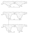
図3に示すように、第1工程で用いられる第1成形型23は、ダイ25と、ダイ25に対して接離可能なパンチ26とからなる。凹部251及び凸部252は、ダイ25の上面に等間隔を空けて交互に形成されている。凸部261及び凹部262は、パンチ26の下面に等間隔を空けて交互に形成されている。凸部261及び凹部262は、凹部251及び凸部252とそれぞれ対応するように配置されている。
図3及び図9に示すように、凹部251及び凸部252,凸部261及び凹部262の各配列ピッチρ1は、張出し部22の配列ピッチρよりやや狭い。凹部251,262の深さ、即ち、凸部252,凸部261の高さβ1は、図2に示す張出し部22の高さβから金属板材21の厚さを減じた値より小さい。凸部252,261の先端は、断面円弧状に形成されている。凹部251及び凹部262の断面は、楕円形である。
図5及び図6に示すように、第2工程で用いられる第2成形型24は、ダイ28と、ダイ28に対して接離可能なパンチ29とからなる。凹部281及び凸部282は、ダイ28の上面に等間隔を空けて交互に形成されている。凸部291及び凹部292は、パンチ29の下面に等間隔を空けて交互に形成されている。凹部281、凸部282、凸部291及び凹部292はいずれも、断面台形状を有している。凸部291及び凹部292は、凹部281及び凸部282とそれぞれ対応するように配置されている。凹部281,292の形状は、張出し部22の外面の形状と近似している。凸部282,291の形状は、張出し部22の内面の形状と近似している。凹部281,292の両端の曲率半径δ3は、張出し部22の外面側両端の曲率半径δよりわずかに小さい。また、凹部281,292の配列ピッチρ2、即ち、凸部282,291の配列ピッチρ2は、図3に示す第1成形型23の配列ピッチρ1よりやや狭い。
図7及び図8に示すように、第3工程で用いられる第3成形型31は、ダイ32と、ダイ32に対して接離可能なパンチ33とからなる。凹部321及び凸部322は、ダイ32の上面に等間隔を空けて交互に形成されている。凸部331及び凹部332は、パンチ33の下面に等間隔を空けて交互に形成されている。凹部321、凸部322、凸部331及び凹部332はいずれも、断面台形状を有している。凸部331及び凹部332は、凹部321及び凸部322とそれぞれ対応するように配置されている。凹部321,332及び凸部322,331の配列ピッチρ3は、第2成形型24の配列ピッチρ2よりやや広く、第1成形型23の配列ピッチρ1よりやや狭い。図6(b)及び図8(b)に示すように、第3成形型31のダイ32及びパンチ33における凹部321,332及び凸部322,331の側壁面の傾斜角度θ3は、第2成形型24の傾斜角度θ1よりも小さい。第3成形型31のその他の寸法は、第2成形型24のそれとほぼ同じである。パンチ33の下死点位置では、ダイ32及びパンチ33の凸部322,331の側壁面間の隙間は、第2成形型24のそれよりやや狭くなっている。
次に、この実施形態の成形方法を説明する。まず、この成形方法における第1工程について説明する。
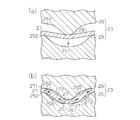
図3に示すように、第1工程において、第1成形型23のダイ25上に、厚さ0.10mmの金属板材21がフラットな状態でセットされる。この状態で、図4(a)及び図4(b)に示すように、パンチ26がダイ25に接近する。すると、パンチ26の凸部261及び凹部262とダイ25の凹部251及び凸部252との間で、金属板材21が裏面と表面とが所定の間隔を空けて交互に張り出される。こうして、波形状の初期張出し部27が成形される。この成形時には、初期張出し部27の頂部271がパンチ26及びダイ25の凸部261,252により押圧されて、初期張出し部27の両側に側壁部272が形成される。パンチ26の下死点位置では、ダイ25及びパンチ26の凹部251,262の内底部は、金属板材21を圧延しない程度に軽く当接するか、或いは当接しなくてもよい。
図3に示すように、第1工程において、第1成形型23のダイ25上に、厚さ0.10mmの金属板材21がフラットな状態でセットされる。この状態で、図4(a)及び図4(b)に示すように、パンチ26がダイ25に接近する。すると、パンチ26の凸部261及び凹部262とダイ25の凹部251及び凸部252との間で、金属板材21が裏面と表面とが所定の間隔を空けて交互に張り出される。こうして、波形状の初期張出し部27が成形される。この成形時には、初期張出し部27の頂部271がパンチ26及びダイ25の凸部261,252により押圧されて、初期張出し部27の両側に側壁部272が形成される。パンチ26の下死点位置では、ダイ25及びパンチ26の凹部251,262の内底部は、金属板材21を圧延しない程度に軽く当接するか、或いは当接しなくてもよい。
このとき、図4(b)から明らかなように、第1成形型23の凸部261,252の曲率半径は、凹部262,251の曲率半径より小さい。このため、側壁部272と凹部262,251の内側面との間には、空間265,255がそれぞれ形成される。空間255,265は、必ずしも形成される必要はない。パンチ26及びダイ25は金属板材21の全面に当接してもよいが、この場合、金属板材21を圧延しない程度に軽く当接させる必要がある。このため、図4(b)の矢印で示すように、頂部271の部分が引き延ばされると共に、頂部271の材料が側壁部272に移動する。その結果、頂部271は0.09mm程度までに薄くなる。
図5に示すように、第2工程において、第2成形型24のダイ28上に、初期張出し部27を有する金属板材21がセットされる。この状態で、パンチ29がダイ28に接近する。すると、図6(a)に示すように、パンチ29及びダイ28の凸部291,282により、初期張出し部27の頂部271が、ダイ28及びパンチ29の凹部281,292に向けて押圧される。このため、初期張出し部27が更に絞られて、引き延ばされる。この場合、成形加工開始時のフラットな状態からの金属板材21の引き延ばし量は、最大40%であり、好ましくは、20%以下である。
その後、図6(b)に示すように、パンチ29及びダイ28における凸部291,282の側壁面と、ダイ28及びパンチ29における凹部281,292の側壁面とにより、初期張出し部27の側壁部272が圧延される。このため、側壁部272の厚さは0.08mm強にまで薄くなり、張出し部22が成形される。このとき、凸部291,282と凹部281,292との間には、張出し部27の頂部271が配置される。この状態で、張出し部27の頂部271は、凸部291,282の先端面と凹部281,292の内面とに当接している。しかしながら、頂部271には、凸部291,282と凹部281,292とによる力がほとんど作用しない。このため、頂部271の厚さは減少しない。
また、この状態で、金属板材21の剛性に基づいて、凸部291,282の基端と金属板材21との間、及び凸部291,282の先端中央と張出し部27の頂部271との間には、空間276,275がそれぞれ形成される。空間275,276は、必ずしも形成される必要はない。つまり、パンチ29及びダイ28を金属板材21の全面に当接させてもよいが、金属板材21が変形しない程度に軽く当接させる必要がある。また、圧延によって側壁部272の厚さが減少すると、図6(b)の矢印で示すように、側壁部272の材料が張出し部22の頂部271に移動する。その結果、図6(a)に示す段階で絞り加工により減少した頂部271の厚さは、側壁部272からの材料移動によって補われる。この場合、側壁部272から頂部271への材料の移動は、空間275,276によって円滑に行なわれる。図6(b)の矢印で示すように、初期張出し部27の側壁部272の材料が頂部271に移動することで、張出し部22の頂部221及び側壁部222は、それらの厚さが0.08強mmに均一化するように成形される。
以上のように、金属板材21に張出し部22が交互に形成されると共に、金属板材21が所定の厚さにまで薄く成形される。第1工程では、金属板材21の引き延ばしによる薄肉化と成形とが行なわれる。第2工程では、金属板材21の圧延による材料移動によって薄肉化と成形とが行なわれる。
図7に示すように、第3工程において、第3成形型31のダイ32上に、張出し部22を有する金属板材21がセットされる。この状態で、パンチ33がダイ32に接近する。すると、図8(a)及び図8(b)に示すように、パンチ33及びダイ32における凸部331,322の側壁面と、ダイ32及びパンチ33における凹部321,332の側壁面とにより、張出し部22の側壁部222が圧延されると共に起立するように整形される。これにより、張出し部22の側壁部222の傾斜角度θ3が小さくなると共に、張出し部22の頂部221が幅方向に拡げられる。
このとき、金属板材21の剛性に基づき、凸部331,322の基端と金属板材21との間、及び凸部331,322の先端中央と張出し部22の頂部221との間には、空間276,275がそれぞれ形成される。空間275,276は、必ずしも形成される必要はない。つまり、パンチ33及びダイ32を金属板材21の全面に当接させてもよいが、金属板材21が変形しない程度に軽く当接させる必要がある。また、圧延によって側壁部222の厚さが減少すると、側壁部222の材料が張出し部22の頂部221に移動する。その結果、図8(a)に示す段階で頂部221が幅方向に拡げられて減少した頂部221の厚さは、側壁部222からの材料移動によって補われる。従って、頂部221の厚さが極端に薄くなることはない。しかも、頂部221が引き延ばされることもほとんどない。よって、張出し部22の厚さは0.08mmに均一化される。この場合も、第2工程と同様に、側壁部222から頂部221への材料の移動は、空間275,276によって円滑に行なわれる。
第1~第3工程において、第2成形型24のパンチ29における凸部291及び凹部292の配列ピッチρ2が、第1成形型23のパンチ26における凸部261及び凹部262の配列ピッチρ1よりも狭い。図示しないが、第2成形型24のダイ28における凹部281及び凸部282の配列ピッチρ2も、第1成形型23のダイ25における凹部251及び凸部252の配列ピッチρ1よりも狭い。
第2工程では、第2成形型24により、初期張出し部27の側壁部272が圧延されて、初期張出し部27の材料が周長に沿って伸びる。しかしながら、初期張出し部27の伸び量は、ダイ28及びパンチ29における凹部281,292及び凸部282,291の配列ピッチρ2を狭くすることによって補正される。つまり、第2工程での初期張出し部27の伸び量を見込んで、配列ピッチρ2を狭くした凹部281,292及び凸部282,291により、初期張出し部27の側壁部272が圧延される。これにより、張出し部22の反りやうねりが抑制される。
第3工程では、第3成形型31が用いられる。第3成形型31のダイ32及びパンチ33における凹部321,332及び凸部322,331の配列ピッチρ3は、第2成形型24のダイ28及びパンチ29における凹部281,292及び凸部282,291の配列ピッチρ2より広い。また、第3成形型31のダイ32及びパンチ33における凹部321,332及び凸部322,331の配列ピッチρ3は、第1成形型23のダイ25及びパンチ26における凹部251,262及び凸部252,261の配列ピッチρ1より狭い。
第3工程では、ダイ32及びパンチ33により、張出し部22の側壁部222がほとんど圧延されることなく、起立するように整形される。このため、張出し部22の材料が周長に沿って大きくは伸びない。このため、第3成形型31の配列ピッチρ3を第2成形型24の配列ピッチρ2と第1成形型23の配列ピッチρ1との間の値に設定することで、張出し部22の最終的な配列ピッチが第1成形型23の配列ピッチρ1に近づけられる
従って、この実施形態によれば、以下のような効果を得ることができる。
従って、この実施形態によれば、以下のような効果を得ることができる。
(1)第1工程では、第1成形型23により、金属板材21に初期張出し部27を形成し、初期張出し部27の頂部271を他の部分よりも薄くする。第2工程及び第3工程では、第2成形型24により、初期張出し部27の側壁部272を圧延して、張出し部22を成形する。
第2工程及び第3工程において、第2成形型24及び第3成形型31により、初期張出し部27の側壁部272が圧延されるとき、側壁部272の材料が頂部271に移動する。このように、金属板材21の張出し部22の引き延ばし成形が、初期の張出し部27の成形を除いて、圧延によって達成される。言い換えれば、引き延ばし成形は第1工程で行なわれ、他の工程では圧延工程が行われる。よって、引き延ばし成形の割合が少なくなるため、金属板材21の破断を防止することができる。従って、張出し部22が高くても、或いは頂部271の幅が広くても、金属板材21を破断せずに成形することができる。尚、燃料電池のセパレータとしては、張出し部22が高く、頂部271の幅が広い方が、冷却水やガス等を案内する機能に優れている。
(2)金属板材21の引き延ばし成形は、第1工程だけで行われる。第2工程以降、金属板材21の薄肉化は、金属板材21を圧延して実行される。このため、金属板材21の破断を防止することができる。しかも、第1工程では、金属板材21が全長の20%しか引き延ばされない。また、第2工程の圧延では、引き延ばされた部分に材料を移動させるため、金属板材21の破断を更に防止することができる。従来工法によれば、ピンホールやクラック等の破断発生による不良率は10~20%であったが、この実施形態の工法によれば、不良率が0.02%にまで低下した。
(3)引き延ばされた張出し部27の頂部271には、圧延された側壁部272の材料が供給される。このため、引き延ばされた頂部271に材料を戻すことができ、張出し部22を均一な厚さに成形することができる。このため、応力の集中が緩和され、成形品の強度分布や応力分布のバランスが良くなる。よって、破断強度を高めることができ、成形品の反りや歪みが抑制される。従って、高精度な成形品を製造することができる。
(4)金属板材21の両面には、複数の張出し部22が襞状に形成されている。この成形品を燃料電池用セパレータとして用いた場合、張出し部22によって、セパレータの両面にガス流路を形成することができる。
(5)第3工程では、第3成形型31により、張出し部22の側壁部222が起立するように整形される。この成形品を燃料電池用セパレータとして用いた場合、張出し部22の側壁部222が起立しているため、セパレータ上に形成されるガス流路の断面積を拡張することができる。
(6)第3工程では、第3成形型31により、張出し部22の頂部221が拡げられる。この場合、張出し部22の頂部221が拡げられるため、他の接合プレートとの接合面積が大きくなり、セパレータ間の接合強度を高めることができる。これにより、セパレータと、セパレータの内側に設けられる発電部材との面圧が分散される。よって、発電部材が破断し難くなる。また、セパレータ上に設けられるガスや冷却水等の流路の断面積が拡張されるため、発電効率も向上する。
(7)第2成形型24のダイ28及びパンチ29における凹部281,292及び凸部282,291の配列ピッチρ2は、第1成形型23のダイ25及びパンチ26における凹部251,262及び凸部252,261の配列ピッチρ1より狭い。このように、第2成形型24の配列ピッチρ2を小さくすることによって、第2工程での側壁部272の圧延による材料の周長に沿った伸びを補正することができる。これにより、成形品の反りやうねりを抑制することができる。
(8)第3成形型31のダイ32及びパンチ33における凹部321,332及び凸部322,331の配列ピッチρ3は、第2成形型24の配列ピッチρ2よりも広く、第1成形型23のダイ25及びパンチ26における凹部251,262及び凸部252,261の配列ピッチρ1よりも狭い。このため、第2工程での金属板材21の延びを見込んで金属板材21を成形することができる。よって、製品の寸法精度が向上する。
上記実施形態を、次のように変更してもよい。
・金属板材21を、燃料電池のセパレータ以外の他の用途、例えば、放熱板の用途に用いてもよい。
・金属板材21を、燃料電池のセパレータ以外の他の用途、例えば、放熱板の用途に用いてもよい。
・第3工程後に、第4工程又は更に次の工程を実行してもよい。第4工程以降の工程では、張出し部22の側壁部222を更に起立させたり、所要箇所に孔を開けたりしてもよい。
・第1工程の前に、別工程を設けてもよい。別工程は、例えば、研磨工程や孔開け工程等であってもよい。
・単一の張出し部のみを形成した金属板材に、前記実施形態の成形方法を実施してもよい。
・単一の張出し部のみを形成した金属板材に、前記実施形態の成形方法を実施してもよい。
・張出し部を、前記実施形態とは別の用途に用いてもよい。例えば、張出し部を、隣接する他の部材とのシール部を構成する突部に具体化してもよい。
・パンチとダイとを入れ換えてもよい。
・パンチとダイとを入れ換えてもよい。
Claims (6)
- ダイとパンチとを有する成形型を用いて、複数の工程により、金属板材に複数の張出し部を成形する成形方法において、
後工程で用いられるダイ及びパンチにおける張出し部成形用の凹部及び凸部の配列ピッチを、前工程で用いられるダイ及びパンチにおける張出し部成形用の凹部及び凸部の配列ピッチより狭くすることを特徴とする金属板材の成形方法。 - 請求項1記載の金属板材の成形方法において、
前記成形方法は、第1~第3工程を備え、
第2工程で用いられる張出し部成形用の凹部及び凸部の配列ピッチを、第1工程で用いられるダイ及びパンチにおける張出し部成形用の凹部及び凸部の配列ピッチより狭くし、
第3工程で用いられる張出し部成形用の凹部及び凸部の配列ピッチを、第1工程で用いられるダイ及びパンチにおける張出し部成形用の凹部及び凸部の配列ピッチより狭くすると共に第2工程で用いられるダイ及びパンチにおける張出し部成形用の凹部及び凸部の配列ピッチより広くすることを特徴とする金属板材の成形方法。 - 請求項1又は2に記載の金属板材の成形方法において、
襞状の張出し部を、前記金属板材の表面と裏面とに交互に形成することを特徴とする金属板材の成形方法。 - 請求項3記載の金属板材の成形方法において、
前記襞状の張出し部を、等間隔に形成することを特徴とする金属板材の成形方法。 - ダイとパンチとを有する成形型を用いて、金属板材に張出し部を成形する成形装置において、
後工程で用いられるダイ及びパンチにおける張出し部成形用の凹部及び凸部の配列ピッチを、前工程で用いられるダイ及びパンチにおける張出し部成形用の凹部及び凸部の配列ピッチより狭くしたことを特徴とする金属板材の成形装置。 - 請求項5記載の金属板材の成形装置において、
前記金属板材に張出し部を形成する第1~第3工程の各工程で用いられるダイとパンチを備え、
第2工程で用いられるダイ及びパンチの張出し部成形用の凹部及び凸部の配列ピッチを、第1工程で用いられるダイ及びパンチにおける張出し部成形用の凹部及び凸部の配列ピッチより狭くし、
第3工程で用いられるダイ及びパンチの凹部及び凸部の配列ピッチを、第1工程で用いられるダイ及びパンチにおける張出し部成形用の凹部及び凸部の配列ピッチより狭くすると共に第2工程で用いられるダイ及びパンチにおける張出し部成形用の凹部及び凸部の配列ピッチより広くしたことを特徴とする金属板材の成形装置。
Priority Applications (3)
| Application Number | Priority Date | Filing Date | Title |
|---|---|---|---|
| US14/785,707 US9962751B2 (en) | 2013-04-24 | 2014-04-24 | Metal plate forming method and forming device |
| EP14788214.6A EP2990132B1 (en) | 2013-04-24 | 2014-04-24 | Metal plate molding method and molding device |
| CN201480021914.4A CN105142815B (zh) | 2013-04-24 | 2014-04-24 | 金属板材的成型方法及成型装置 |
Applications Claiming Priority (2)
| Application Number | Priority Date | Filing Date | Title |
|---|---|---|---|
| JP2013091506A JP6032115B2 (ja) | 2013-04-24 | 2013-04-24 | 金属板材の成形方法及び成形装置 |
| JP2013-091506 | 2013-04-24 |
Publications (1)
| Publication Number | Publication Date |
|---|---|
| WO2014175391A1 true WO2014175391A1 (ja) | 2014-10-30 |
Family
ID=51791957
Family Applications (1)
| Application Number | Title | Priority Date | Filing Date |
|---|---|---|---|
| PCT/JP2014/061593 Ceased WO2014175391A1 (ja) | 2013-04-24 | 2014-04-24 | 金属板材の成形方法及び成形装置 |
Country Status (5)
| Country | Link |
|---|---|
| US (1) | US9962751B2 (ja) |
| EP (1) | EP2990132B1 (ja) |
| JP (1) | JP6032115B2 (ja) |
| CN (1) | CN105142815B (ja) |
| WO (1) | WO2014175391A1 (ja) |
Cited By (2)
| Publication number | Priority date | Publication date | Assignee | Title |
|---|---|---|---|---|
| JP2017080782A (ja) * | 2015-10-28 | 2017-05-18 | 日新製鋼株式会社 | 金属プレートの製造方法、及び該製造方法により製造された金属プレートのプレート式熱交換器への使用 |
| JP2017080781A (ja) * | 2015-10-28 | 2017-05-18 | 日新製鋼株式会社 | 金属プレートの製造方法、及び該製造方法により製造された金属プレートのプレート式熱交換器への使用 |
Families Citing this family (17)
| Publication number | Priority date | Publication date | Assignee | Title |
|---|---|---|---|---|
| US10479016B2 (en) * | 2015-01-26 | 2019-11-19 | Stephen J. Motosko | Polycarbonate panel having shallow bends |
| JP6664989B2 (ja) * | 2015-02-24 | 2020-03-13 | 日鉄日新製鋼株式会社 | 金属プレート及びプレート式熱交換器 |
| JP6457856B2 (ja) * | 2015-03-25 | 2019-01-23 | 日新製鋼株式会社 | 連続波形状製品の製造方法 |
| JP6486774B2 (ja) * | 2015-06-12 | 2019-03-20 | 株式会社三井ハイテック | 金属板の成形方法及びこれに用いる成形装置 |
| JP6699259B2 (ja) * | 2016-03-11 | 2020-05-27 | 富士ゼロックス株式会社 | 金属筒状体の製造方法、電子写真感光体用基材の製造方法、及び電子写真感光体の製造方法 |
| CN106424260A (zh) * | 2016-09-30 | 2017-02-22 | 华中科技大学 | 小尺寸波纹薄板压制方法及装置 |
| US20180248203A1 (en) * | 2017-02-28 | 2018-08-30 | GM Global Technology Operations LLC | System and method for manufacturing channels in a bipolar plate |
| JP6721544B2 (ja) * | 2017-06-28 | 2020-07-15 | 株式会社神戸製鋼所 | プレス成形品の製造方法 |
| DE102017219418A1 (de) * | 2017-10-30 | 2019-05-02 | Robert Bosch Gmbh | Gasverteilerplatte zur Gasverteilung und Strömungsführung in Elektrolyseuren und Brennstoffzellen |
| JP6927025B2 (ja) * | 2017-12-26 | 2021-08-25 | トヨタ車体株式会社 | 燃料電池用セパレータの製造装置及び燃料電池用セパレータの製造方法 |
| JP7100878B2 (ja) * | 2018-01-26 | 2022-07-14 | 株式会社カネミツ | 金属板の加工方法 |
| JP7017944B2 (ja) * | 2018-02-09 | 2022-02-09 | 株式会社三井ハイテック | 金属成形体の製造方法 |
| JP6957400B2 (ja) * | 2018-03-27 | 2021-11-02 | 本田技研工業株式会社 | 金属板材の成形方法 |
| CN110752385B (zh) * | 2019-09-05 | 2021-06-11 | 太原科技大学 | 一种燃料电池金属双极板直流道成形方法 |
| IT202000025363A1 (it) * | 2020-10-27 | 2022-04-27 | Marelli Europe Spa | Modulo elettronico sigillato munito di mezzi di fissaggio perfezionati, e relativo metodo di assemblaggio |
| US12016555B2 (en) * | 2020-11-10 | 2024-06-25 | Cilag Gmbh International | Method of forming an anvil for a surgical stapler |
| CN113967691B (zh) * | 2021-10-21 | 2022-11-15 | 无锡微研股份有限公司 | 一种氢能源电池金属板的生产工艺 |
Citations (12)
| Publication number | Priority date | Publication date | Assignee | Title |
|---|---|---|---|---|
| US1425208A (en) * | 1919-04-29 | 1922-08-08 | Bert B Milner | Method of manufacturing corrugated metal plates |
| DE459970C (de) * | 1924-12-28 | 1928-05-16 | Paul Seydel | Verfahren zur Herstellung von zickzackfoermigen Blechkoerpern |
| JPS538354A (en) * | 1976-07-12 | 1978-01-25 | Nippon Koki Kk | Method of fabricating metal decorative plate |
| JPS63194823A (ja) * | 1987-02-06 | 1988-08-12 | Showa Aircraft Ind Co Ltd | 波板の成形プレス型 |
| JPH071044A (ja) * | 1993-06-18 | 1995-01-06 | Nikko Kogyo:Kk | 波賦形金属板の製造法 |
| JP2000138065A (ja) | 1998-11-02 | 2000-05-16 | Toyota Motor Corp | 燃料電池用金属セパレータ |
| JP2002175818A (ja) | 2000-12-05 | 2002-06-21 | Honda Motor Co Ltd | 燃料電池用セパレータおよび燃料電池 |
| JP2002313354A (ja) * | 2001-04-11 | 2002-10-25 | Nippon Steel Corp | 固体高分子型燃料電池用セパレータ製造方法及びその製造装置 |
| JP2003249241A (ja) | 2002-02-25 | 2003-09-05 | Miyoshi Kogyo Kk | 燃料電池用の金属セパレータの製造方法 |
| JP2007098413A (ja) * | 2005-09-30 | 2007-04-19 | Denso Corp | オフセット形状フィンのピッチ変更方法及びピッチ変更装置 |
| JP2007167886A (ja) * | 2005-12-21 | 2007-07-05 | Topre Corp | 金属薄板の成形方法 |
| JP2010167441A (ja) * | 2009-01-22 | 2010-08-05 | Topre Corp | 凹凸部が形成された金属薄板の製造方法 |
Family Cites Families (23)
| Publication number | Priority date | Publication date | Assignee | Title |
|---|---|---|---|---|
| CH358773A (de) | 1958-05-12 | 1961-12-15 | Aluminium Ind Ag | Verfahren und Vorrichtung zur Herstellung von metallenen längsgewellten Bändern |
| US3194047A (en) | 1962-04-24 | 1965-07-13 | Budd Co | Method of making a metal sandwich structure panel |
| JP2692165B2 (ja) | 1988-08-16 | 1997-12-17 | 日産自動車株式会社 | ディンプルプレートの成形方法 |
| JP4204018B2 (ja) | 1998-03-30 | 2009-01-07 | 東プレ株式会社 | プレス成形品の平面度矯正方法 |
| JP2000317531A (ja) | 1999-05-10 | 2000-11-21 | Toyota Central Res & Dev Lab Inc | 板材のプレス加工方法 |
| JP3807192B2 (ja) | 2000-05-17 | 2006-08-09 | セイコーエプソン株式会社 | 部品取付軸の製造方法 |
| US6701603B2 (en) | 2000-12-13 | 2004-03-09 | Asmo Co., Ltd. | Method of manufacturing yoke of electric rotating machine |
| JP3766300B2 (ja) | 2001-06-08 | 2006-04-12 | アスモ株式会社 | 回転電機のヨークとその製造方法 |
| FR2820654B1 (fr) * | 2001-02-09 | 2003-09-26 | Air Liquide | Procede et dispositif de fabrication d'une onde de garnissage structure, et appareil de traitement de fluides correspondant |
| JP2003161317A (ja) | 2001-11-26 | 2003-06-06 | Kyoei Technica Kk | 偏芯駆動軸連結装置、および駆動特性計測装置。 |
| JP2003181550A (ja) | 2001-12-13 | 2003-07-02 | Nakamura Mfg Co Ltd | 電子記憶装置の突軸形成方法 |
| JP4065832B2 (ja) * | 2003-12-03 | 2008-03-26 | 本田技研工業株式会社 | 燃料電池用金属製セパレータのプレス成形装置及びプレス成形方法 |
| JP4388389B2 (ja) * | 2004-02-24 | 2009-12-24 | 本田技研工業株式会社 | 燃料電池用金属製セパレータの製造方法 |
| JP2006281312A (ja) | 2005-04-05 | 2006-10-19 | Nissan Motor Co Ltd | プレス加工方法 |
| US20070029073A1 (en) | 2005-08-04 | 2007-02-08 | Denso Corporation | Production method of offset-shaped fins, fins, and method and apparatus for changing pitch of fins |
| CN201291258Y (zh) * | 2008-11-06 | 2009-08-19 | 上海理工大学 | 凸凹模移动式波纹板成形装置 |
| JP5381647B2 (ja) | 2009-11-26 | 2014-01-08 | トヨタ紡織株式会社 | 燃料電池用セパレータ及びその製造方法 |
| DE102009059197A1 (de) | 2009-12-17 | 2011-06-22 | ThyssenKrupp Steel Europe AG, 47166 | Verfahren und Vorrichtung zur Herstellung eines Halbschalenteils |
| JP5573511B2 (ja) | 2010-09-02 | 2014-08-20 | トヨタ紡織株式会社 | 成形体の製造方法 |
| JP5609830B2 (ja) * | 2011-09-15 | 2014-10-22 | 新日鐵住金株式会社 | パネル材 |
| US8720247B2 (en) | 2011-11-22 | 2014-05-13 | Denso Corporation | Method for bending process and processing machine |
| CN102997741B (zh) | 2012-11-30 | 2014-12-03 | 艾普尔换热器(苏州)有限公司 | 一种换热器翅片及其制造方法 |
| JP6028671B2 (ja) | 2013-04-24 | 2016-11-16 | トヨタ紡織株式会社 | 金属板材の成形方法及び成形装置 |
-
2013
- 2013-04-24 JP JP2013091506A patent/JP6032115B2/ja active Active
-
2014
- 2014-04-24 EP EP14788214.6A patent/EP2990132B1/en active Active
- 2014-04-24 US US14/785,707 patent/US9962751B2/en active Active
- 2014-04-24 WO PCT/JP2014/061593 patent/WO2014175391A1/ja not_active Ceased
- 2014-04-24 CN CN201480021914.4A patent/CN105142815B/zh active Active
Patent Citations (12)
| Publication number | Priority date | Publication date | Assignee | Title |
|---|---|---|---|---|
| US1425208A (en) * | 1919-04-29 | 1922-08-08 | Bert B Milner | Method of manufacturing corrugated metal plates |
| DE459970C (de) * | 1924-12-28 | 1928-05-16 | Paul Seydel | Verfahren zur Herstellung von zickzackfoermigen Blechkoerpern |
| JPS538354A (en) * | 1976-07-12 | 1978-01-25 | Nippon Koki Kk | Method of fabricating metal decorative plate |
| JPS63194823A (ja) * | 1987-02-06 | 1988-08-12 | Showa Aircraft Ind Co Ltd | 波板の成形プレス型 |
| JPH071044A (ja) * | 1993-06-18 | 1995-01-06 | Nikko Kogyo:Kk | 波賦形金属板の製造法 |
| JP2000138065A (ja) | 1998-11-02 | 2000-05-16 | Toyota Motor Corp | 燃料電池用金属セパレータ |
| JP2002175818A (ja) | 2000-12-05 | 2002-06-21 | Honda Motor Co Ltd | 燃料電池用セパレータおよび燃料電池 |
| JP2002313354A (ja) * | 2001-04-11 | 2002-10-25 | Nippon Steel Corp | 固体高分子型燃料電池用セパレータ製造方法及びその製造装置 |
| JP2003249241A (ja) | 2002-02-25 | 2003-09-05 | Miyoshi Kogyo Kk | 燃料電池用の金属セパレータの製造方法 |
| JP2007098413A (ja) * | 2005-09-30 | 2007-04-19 | Denso Corp | オフセット形状フィンのピッチ変更方法及びピッチ変更装置 |
| JP2007167886A (ja) * | 2005-12-21 | 2007-07-05 | Topre Corp | 金属薄板の成形方法 |
| JP2010167441A (ja) * | 2009-01-22 | 2010-08-05 | Topre Corp | 凹凸部が形成された金属薄板の製造方法 |
Cited By (2)
| Publication number | Priority date | Publication date | Assignee | Title |
|---|---|---|---|---|
| JP2017080782A (ja) * | 2015-10-28 | 2017-05-18 | 日新製鋼株式会社 | 金属プレートの製造方法、及び該製造方法により製造された金属プレートのプレート式熱交換器への使用 |
| JP2017080781A (ja) * | 2015-10-28 | 2017-05-18 | 日新製鋼株式会社 | 金属プレートの製造方法、及び該製造方法により製造された金属プレートのプレート式熱交換器への使用 |
Also Published As
| Publication number | Publication date |
|---|---|
| US9962751B2 (en) | 2018-05-08 |
| EP2990132A1 (en) | 2016-03-02 |
| CN105142815B (zh) | 2017-03-08 |
| CN105142815A (zh) | 2015-12-09 |
| JP6032115B2 (ja) | 2016-11-24 |
| JP2014213345A (ja) | 2014-11-17 |
| EP2990132B1 (en) | 2019-06-12 |
| US20160067756A1 (en) | 2016-03-10 |
| EP2990132A4 (en) | 2016-12-07 |
Similar Documents
| Publication | Publication Date | Title |
|---|---|---|
| WO2014175391A1 (ja) | 金属板材の成形方法及び成形装置 | |
| JP6028671B2 (ja) | 金属板材の成形方法及び成形装置 | |
| JP6103147B2 (ja) | 燃料電池セパレータ成形用微細成形型、燃料電池セパレータの製造方法、及び、燃料電池セパレータ | |
| CN102380534B (zh) | 成形体的制造方法 | |
| KR101643091B1 (ko) | 각형 전지 케이스의 성형 방법 | |
| JP6798292B2 (ja) | 金属板材の成形方法及び成形装置 | |
| JP2018089672A (ja) | 金属板材の成形方法及び成形装置 | |
| JP6481532B2 (ja) | 金属板材の成形方法及び金属板材の成形装置 | |
| JP5271728B2 (ja) | 凹凸部が形成された金属薄板の製造方法 | |
| TWI614068B (zh) | 成形材料製造方法及其成形材料 | |
| JP6056808B2 (ja) | 溝形状部を有するプレートのプレス成形方法 | |
| JP2019139966A (ja) | 金属成形体の製造方法 | |
| JP2014213344A (ja) | プレス加工方法及び成形装置 | |
| JP2011147976A (ja) | プレス成形金型 | |
| JP4769570B2 (ja) | 金属薄板の成形方法 | |
| JP5196945B2 (ja) | セルガイド用形鋼の製造方法およびその製造に用いる中間素材 | |
| JP2020066051A (ja) | エンボス金属板及びその製造方法 | |
| JP2005040797A (ja) | 金属板の液圧成形方法 |
Legal Events
| Date | Code | Title | Description |
|---|---|---|---|
| WWE | Wipo information: entry into national phase |
Ref document number: 201480021914.4 Country of ref document: CN |
|
| 121 | Ep: the epo has been informed by wipo that ep was designated in this application |
Ref document number: 14788214 Country of ref document: EP Kind code of ref document: A1 |
|
| WWE | Wipo information: entry into national phase |
Ref document number: 2014788214 Country of ref document: EP |
|
| WWE | Wipo information: entry into national phase |
Ref document number: 14785707 Country of ref document: US |
|
| NENP | Non-entry into the national phase |
Ref country code: DE |