WO2014181469A1 - 吸水処理材及びその製造方法 - Google Patents
吸水処理材及びその製造方法 Download PDFInfo
- Publication number
- WO2014181469A1 WO2014181469A1 PCT/JP2013/063180 JP2013063180W WO2014181469A1 WO 2014181469 A1 WO2014181469 A1 WO 2014181469A1 JP 2013063180 W JP2013063180 W JP 2013063180W WO 2014181469 A1 WO2014181469 A1 WO 2014181469A1
- Authority
- WO
- WIPO (PCT)
- Prior art keywords
- water
- absorbing
- treatment material
- fluff pulp
- absorbing polymer
- Prior art date
- Legal status (The legal status is an assumption and is not a legal conclusion. Google has not performed a legal analysis and makes no representation as to the accuracy of the status listed.)
- Ceased
Links
Images






Classifications
-
- B—PERFORMING OPERATIONS; TRANSPORTING
- B01—PHYSICAL OR CHEMICAL PROCESSES OR APPARATUS IN GENERAL
- B01J—CHEMICAL OR PHYSICAL PROCESSES, e.g. CATALYSIS OR COLLOID CHEMISTRY; THEIR RELEVANT APPARATUS
- B01J20/00—Solid sorbent compositions or filter aid compositions; Sorbents for chromatography; Processes for preparing, regenerating or reactivating thereof
- B01J20/22—Solid sorbent compositions or filter aid compositions; Sorbents for chromatography; Processes for preparing, regenerating or reactivating thereof comprising organic material
-
- A—HUMAN NECESSITIES
- A01—AGRICULTURE; FORESTRY; ANIMAL HUSBANDRY; HUNTING; TRAPPING; FISHING
- A01K—ANIMAL HUSBANDRY; AVICULTURE; APICULTURE; PISCICULTURE; FISHING; REARING OR BREEDING ANIMALS, NOT OTHERWISE PROVIDED FOR; NEW BREEDS OF ANIMALS
- A01K1/00—Housing animals; Equipment therefor
- A01K1/015—Floor coverings, e.g. bedding-down sheets ; Stable floors
- A01K1/0152—Litter
- A01K1/0155—Litter comprising organic material
-
- B—PERFORMING OPERATIONS; TRANSPORTING
- B01—PHYSICAL OR CHEMICAL PROCESSES OR APPARATUS IN GENERAL
- B01J—CHEMICAL OR PHYSICAL PROCESSES, e.g. CATALYSIS OR COLLOID CHEMISTRY; THEIR RELEVANT APPARATUS
- B01J20/00—Solid sorbent compositions or filter aid compositions; Sorbents for chromatography; Processes for preparing, regenerating or reactivating thereof
- B01J20/30—Processes for preparing, regenerating, or reactivating
- B01J20/3028—Granulating, agglomerating or aggregating
-
- B—PERFORMING OPERATIONS; TRANSPORTING
- B01—PHYSICAL OR CHEMICAL PROCESSES OR APPARATUS IN GENERAL
- B01J—CHEMICAL OR PHYSICAL PROCESSES, e.g. CATALYSIS OR COLLOID CHEMISTRY; THEIR RELEVANT APPARATUS
- B01J20/00—Solid sorbent compositions or filter aid compositions; Sorbents for chromatography; Processes for preparing, regenerating or reactivating thereof
- B01J20/30—Processes for preparing, regenerating, or reactivating
- B01J20/32—Impregnating or coating ; Solid sorbent compositions obtained from processes involving impregnating or coating
- B01J20/3291—Characterised by the shape of the carrier, the coating or the obtained coated product
- B01J20/3293—Coatings on a core, the core being particle or fiber shaped, e.g. encapsulated particles, coated fibers
-
- B—PERFORMING OPERATIONS; TRANSPORTING
- B03—SEPARATION OF SOLID MATERIALS USING LIQUIDS OR USING PNEUMATIC TABLES OR JIGS; MAGNETIC OR ELECTROSTATIC SEPARATION OF SOLID MATERIALS FROM SOLID MATERIALS OR FLUIDS; SEPARATION BY HIGH-VOLTAGE ELECTRIC FIELDS
- B03B—SEPARATING SOLID MATERIALS USING LIQUIDS OR USING PNEUMATIC TABLES OR JIGS
- B03B9/00—General arrangement of separating plant, e.g. flow sheets
- B03B9/06—General arrangement of separating plant, e.g. flow sheets specially adapted for refuse
- B03B9/061—General arrangement of separating plant, e.g. flow sheets specially adapted for refuse the refuse being industrial
-
- B—PERFORMING OPERATIONS; TRANSPORTING
- B07—SEPARATING SOLIDS FROM SOLIDS; SORTING
- B07B—SEPARATING SOLIDS FROM SOLIDS BY SIEVING, SCREENING, SIFTING OR BY USING GAS CURRENTS; SEPARATING BY OTHER DRY METHODS APPLICABLE TO BULK MATERIAL, e.g. LOOSE ARTICLES FIT TO BE HANDLED LIKE BULK MATERIAL
- B07B1/00—Sieving, screening, sifting, or sorting solid materials using networks, gratings, grids, or the like
- B07B1/18—Drum screens
- B07B1/22—Revolving drums
- B07B1/24—Revolving drums with fixed or moving interior agitators
-
- B—PERFORMING OPERATIONS; TRANSPORTING
- B29—WORKING OF PLASTICS; WORKING OF SUBSTANCES IN A PLASTIC STATE IN GENERAL
- B29B—PREPARATION OR PRETREATMENT OF THE MATERIAL TO BE SHAPED; MAKING GRANULES OR PREFORMS; RECOVERY OF PLASTICS OR OTHER CONSTITUENTS OF WASTE MATERIAL CONTAINING PLASTICS
- B29B17/00—Recovery of plastics or other constituents of waste material containing plastics
- B29B17/02—Separating plastics from other materials
-
- B—PERFORMING OPERATIONS; TRANSPORTING
- B01—PHYSICAL OR CHEMICAL PROCESSES OR APPARATUS IN GENERAL
- B01J—CHEMICAL OR PHYSICAL PROCESSES, e.g. CATALYSIS OR COLLOID CHEMISTRY; THEIR RELEVANT APPARATUS
- B01J2220/00—Aspects relating to sorbent materials
- B01J2220/40—Aspects relating to the composition of sorbent or filter aid materials
- B01J2220/48—Sorbents characterised by the starting material used for their preparation
- B01J2220/4812—Sorbents characterised by the starting material used for their preparation the starting material being of organic character
- B01J2220/4825—Polysaccharides or cellulose materials, e.g. starch, chitin, sawdust, wood, straw, cotton
- B01J2220/4831—Polysaccharides or cellulose materials, e.g. starch, chitin, sawdust, wood, straw, cotton having been subjected to further processing, e.g. paper, cellulose pulp
-
- B—PERFORMING OPERATIONS; TRANSPORTING
- B01—PHYSICAL OR CHEMICAL PROCESSES OR APPARATUS IN GENERAL
- B01J—CHEMICAL OR PHYSICAL PROCESSES, e.g. CATALYSIS OR COLLOID CHEMISTRY; THEIR RELEVANT APPARATUS
- B01J2220/00—Aspects relating to sorbent materials
- B01J2220/50—Aspects relating to the use of sorbent or filter aid materials
- B01J2220/68—Superabsorbents
-
- B—PERFORMING OPERATIONS; TRANSPORTING
- B29—WORKING OF PLASTICS; WORKING OF SUBSTANCES IN A PLASTIC STATE IN GENERAL
- B29L—INDEXING SCHEME ASSOCIATED WITH SUBCLASS B29C, RELATING TO PARTICULAR ARTICLES
- B29L2031/00—Other particular articles
- B29L2031/48—Wearing apparel
- B29L2031/4871—Underwear
- B29L2031/4878—Diapers, napkins
-
- Y—GENERAL TAGGING OF NEW TECHNOLOGICAL DEVELOPMENTS; GENERAL TAGGING OF CROSS-SECTIONAL TECHNOLOGIES SPANNING OVER SEVERAL SECTIONS OF THE IPC; TECHNICAL SUBJECTS COVERED BY FORMER USPC CROSS-REFERENCE ART COLLECTIONS [XRACs] AND DIGESTS
- Y02—TECHNOLOGIES OR APPLICATIONS FOR MITIGATION OR ADAPTATION AGAINST CLIMATE CHANGE
- Y02W—CLIMATE CHANGE MITIGATION TECHNOLOGIES RELATED TO WASTEWATER TREATMENT OR WASTE MANAGEMENT
- Y02W30/00—Technologies for solid waste management
- Y02W30/50—Reuse, recycling or recovery technologies
- Y02W30/52—Mechanical processing of waste for the recovery of materials, e.g. crushing, shredding, separation or disassembly
-
- Y—GENERAL TAGGING OF NEW TECHNOLOGICAL DEVELOPMENTS; GENERAL TAGGING OF CROSS-SECTIONAL TECHNOLOGIES SPANNING OVER SEVERAL SECTIONS OF THE IPC; TECHNICAL SUBJECTS COVERED BY FORMER USPC CROSS-REFERENCE ART COLLECTIONS [XRACs] AND DIGESTS
- Y02—TECHNOLOGIES OR APPLICATIONS FOR MITIGATION OR ADAPTATION AGAINST CLIMATE CHANGE
- Y02W—CLIMATE CHANGE MITIGATION TECHNOLOGIES RELATED TO WASTEWATER TREATMENT OR WASTE MANAGEMENT
- Y02W30/00—Technologies for solid waste management
- Y02W30/50—Reuse, recycling or recovery technologies
- Y02W30/62—Plastics recycling; Rubber recycling
Definitions
- the present invention relates to a water-absorbing treatment material that absorbs liquid such as human or animal excrement and a method for producing the same.
- Patent Document 1 describes an excrement treatment material which is a kind of water absorption treatment material.
- a crushed material of waste paper diaper is used as a material.
- the use of materials obtained from waste materials of sanitary goods such as disposable diapers contributes to a reduction in material procurement costs and, in turn, a reduction in manufacturing costs for water-absorbing treatment materials.
- the water-absorbing polymer contained in the sanitary product is attached to the material.
- the water-absorbing treatment material that has absorbed the liquid tends to collapse from the inside due to excessive swelling of the water-absorbing polymer. This leads to a deterioration in the quality of the water absorption treatment material.
- This invention is made
- the water-absorbing treatment material according to the present invention contains a water-absorbing material composed of at least one of the plastic and the fluff pulp obtained by separating the water-absorbing polymer from a sanitary article including plastic, fluff pulp and a water-absorbing polymer.
- a weight ratio of the water-absorbing polymer adhering to the water-absorbing material to the water-absorbing material is 3% or less.
- this water-absorbing treatment material a water-absorbing material made of at least one of plastic and fluff pulp obtained by separating a water-absorbing polymer from sanitary goods is used.
- a water absorption material can be acquired from the waste material of sanitary goods, the procurement cost of a material can be reduced and by extension, the manufacturing cost of a water absorption treatment material can be reduced.
- the weight ratio of the water-absorbing polymer remaining in the water-absorbing material is only 3% or less, the quality of the water-absorbing treatment material can be prevented from deteriorating.
- the method for producing a water-absorbing treatment material comprises separating the water-absorbing polymer from a sanitary article including plastic, fluff pulp and water-absorbing polymer, and providing a water-absorbing material comprising at least one of the plastic and fluff pulp.
- the water-absorbing polymer is separated from the sanitary product so that the weight ratio with respect to is 3% or less.
- a water-absorbing material made of at least one of plastic and fluff pulp obtained by separating a water-absorbing polymer from sanitary goods is used.
- a water absorption material can be acquired from the waste material of sanitary goods, the procurement cost of a material can be reduced and by extension, the manufacturing cost of a water absorption treatment material can be reduced.
- the weight ratio of the water-absorbing polymer remaining in the water-absorbing material is only 3% or less, it is possible to prevent deterioration in the quality of the water-absorbing treatment material.
- a water-absorbing treatment material that can be produced at low cost without causing quality degradation and a method for producing the same are realized.
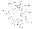
- FIG. 4 is a sectional view taken along line IV-IV in FIG. 3.
- FIG. 6 is a cross-sectional view taken along line VI-VI in FIG. 5.
- FIG. 1 is a schematic view showing an embodiment of a water-absorbing treatment material according to the present invention.
- the water absorption treatment material 1 is an excrement treatment material for pets such as cats and dogs, and includes a granular core portion 10 and a coating layer portion 20.
- the granular core part 10 has a function of absorbing and retaining liquid.
- This granular core 10 contains a water-absorbing material made of at least one of plastic derived from sanitary goods and fluff pulp. That is, the granular core part 10 may contain only one of such plastics and fluff pulp, or may contain both.
- Plastic and fluff pulp are specifically obtained by separating the water-absorbing polymer from sanitary goods including plastic, fluff pulp and water-absorbing polymer (including highly water-absorbing polymer; the same shall apply hereinafter). This separation is performed by a separation device to be described later.
- the sanitary product is, for example, a paper diaper, a sanitary napkin, or a urine picking pad. As the sanitary goods, it is preferable to use sanitary goods as waste.
- the weight ratio of the water-absorbing polymer adhering to the plastic to the plastic is 3% or less (preferably 1% or less).
- the weight ratio of the water-absorbing polymer adhering to the fluff pulp to the fluff pulp is also 3% or less (preferably 1% or less). Therefore, the weight ratio of the water-absorbing polymer adhering to the water-absorbing material made of at least one of these plastics and fluff pulp to the water-absorbing material is also 3% or less (preferably 1% or less).
- the weight ratio of the plastic piece to the fluff pulp is preferably 5% or less.
- the water-absorbing material is the main material of the water-absorbing treatment material 1.
- the main material of the water-absorbing treatment material 1 refers to a material having the highest weight ratio in the entire material constituting the water-absorbing treatment material 1.
- the water absorbing material is also the main material of the granular core part 10. That is, the water-absorbing material occupies the highest weight ratio among all the materials constituting the granular core portion 10.
- the covering layer portion 20 covers the granular core portion 10.
- the covering layer portion 20 may cover the entire surface of the granular core portion 10 or may cover only a part of the surface of the granular core portion 10.
- the covering layer portion 20 has a function (blocking function) for adhering the water-absorbing treatment materials 1 wetted with excrement such as urine during use to form a lump.
- the coating layer portion 20 contains fluff pulp and a water-absorbing polymer. These fluff pulp and water-absorbing polymer are all derived from sanitary goods. That is, these fluff pulp and water-absorbing polymer are both separated from sanitary goods. The fluff pulp and the water-absorbing polymer contained in the coating layer portion 20 may be separated from each other or may not be separated.
- the fluff pulp and the water-absorbing polymer contained in the coating layer part 20 are each pulverized to a predetermined particle size.
- the fluff pulp is preferably pulverized to a particle size of less than 1 mm.
- the water-absorbing polymer is preferably pulverized to a particle size of less than 35 ⁇ m.
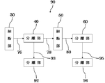
- FIG. 2 is a configuration diagram showing a separation device used in the present embodiment.
- the separation apparatus 90 separates the second material and the third material from the processing object by processing the processing object including the first material, the second material, and the third material, and further The second material and the third material are separated from each other.
- the object to be treated is a sanitary product
- the first material is plastic
- the second material is fluff pulp
- the third material is a water-absorbing polymer.
- the separation device 90 includes a shredder 30 (first shredder), a separator 40 (first rough separator), a separator 92 (first fine separator), and a shredder 50 (second shredder).
- the shredding unit 30 shreds sanitary goods.
- a crusher or a pulverizer can be used.
- the shredder 30 is not provided with a screen.
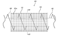
- FIG. 3 is a side view showing the separation unit 40.
- FIG. 4 is a cross-sectional view taken along line IV-IV in FIG.
- the separation part 40 has a drum 42 (first cylindrical part).
- the drum 42 has a substantially cylindrical shape and is provided so as to be rotatable around its central axis.
- the central axis of the drum 42 is horizontal.
- the inner diameter of the drum 42 is, for example, 30 cm or more and 50 cm or less.
- the drum 42 has a large number of holes 42a (first holes).
- the hole 42 a is formed over substantially the entire drum 42.
- the hole 42a does not allow the plastic contained in the sanitary article shredded by the shredder 30 to pass, but allows the fluff pulp and the water-absorbing polymer to pass.
- the diameter of the hole 42a is preferably 10 mm or more and 30 mm or less.
- the separation unit 40 separates the fluff pulp and the water-absorbing polymer that have passed through the holes 42a from the sanitary product by rotating the drum 42 in a state where the sanitary product shredded by the shredding unit 30 is accommodated.
- a protrusion 44 (first protrusion) is provided on the inner peripheral surface of the drum 42.
- the protrusion 44 extends in the central axis direction of the drum 42.
- the protrusion 44 extends over substantially the entire path from the inlet side (left side in FIG. 3) to the outlet side (right side in FIG. 3) of the drum 42. Further, the protrusion 44 has a substantially triangular cross section.
- the height of the protrusion 44 (the length in the radial direction of the drum 42) is, for example, 5 mm or more and 2 cm or less. It is preferable that p protrusions 44 are provided (p: an integer of 3 to 5).
- the p protrusions 44 are arranged on the inner peripheral surface of the drum 42 at equal intervals.
- Rotating rod 46 and screw member 48 are provided inside drum 42.
- the rotating rod 46 has a substantially cylindrical shape, and is provided so as to be rotatable around its central axis.
- the central axis of the rotating rod 46 coincides with the central axis of the drum 42.
- the rotating rod 46 rotates independently of the drum 42.
- the outer diameter of the rotating rod 46 is, for example, not less than 15 cm and not more than 25 cm.
- a screw member 48 is provided around the rotating rod 46 so as to draw a spiral.
- the screw member 48 is fixed to the rotating rod 46 and rotates together with the rotating rod 46.
- a plurality of teeth 49 are formed on the screw member 48.
- the end portion of the tooth 49 is constituted by a side 49a and a side 49b in a front view (see FIG. 4).
- the side 49 a extends in the radial direction of the drum 42 and the rotating rod 46.
- the inner end of the side 49 a (the end closer to the rotating rod 46) exists at a position away from the rotating rod 46.
- the outer end of the side 49 a (the end closer to the drum 42) exists at a position away from the drum 42.
- the distance between the outer end of the side 49a and the inner peripheral surface of the drum 42 is larger than the height of the protrusion 44, and is, for example, 1 cm or more and 3 cm or less.
- the side 49 b connects the outer end of the side 49 a and the inner end of the side 49 a of the adjacent tooth 49.
- the side 49b is longer than the side 49a.
- the ratio of the length of the side 49b to the length of the side 49a is, for example, not less than 2 and not more than 2.5.
- Rotating rod 46 and screw member 48 rotate counterclockwise (counterclockwise) in FIG. That is, in the tooth 49, the side 49b is positioned forward in the rotational direction, and the side 49a is positioned rearward in the rotational direction.
- the rotation direction of the drum 42 described above may be the same as or opposite to the rotation direction of the rotation rod 46 and the screw member 48. When these rotational directions are the same, it is preferable that the rotational speed of the rotating rod 46 and the screw member 48 is larger than the rotational speed of the drum 42.
- the separation unit 92 separates the fluff pulp and the water-absorbing polymer separated from the sanitary article by the separation unit 40.
- This separation can be performed, for example, by a method of injecting air to a mixture of fluff pulp and a water-absorbing polymer. This method utilizes a difference in specific gravity between fluff pulp and a water-absorbing polymer. Specifically, both the fluff pulp and the water-absorbing polymer are separated from each other by jetting air with such strength that only the former is blown away.
- the shredded part 50 shreds sanitary goods from which the fluff pulp and the water-absorbing polymer that have passed through the holes 42a are separated by the separating part 40.
- a crusher or a pulverizer can be used as the shredder 50.
- the shredder 50 is provided with a screen.
- the hole diameter of the screen is preferably 30 mm or more and 70 mm or less.
- FIG. 5 is a side view showing the separation unit 60.
- FIG. 6 is a cross-sectional view taken along line VI-VI in FIG.
- the separation part 60 has a drum 62 (second cylindrical part).
- the drum 62 has a substantially cylindrical shape, and is provided so as to be rotatable around its central axis.
- the central axis of the drum 62 is horizontal.
- the inner diameter of the drum 62 is, for example, not less than 30 cm and not more than 50 cm.
- the drum 62 has a large number of holes 62a (second holes).
- the hole 62 a is formed over substantially the entire drum 62.
- the hole 62a does not allow the plastic contained in the sanitary article cut by the shredder 50 to pass through, but allows the fluff pulp and the water-absorbing polymer to pass through.
- the area of the hole 62a in plan view is smaller than the area of the hole 42a in plan view.
- the diameter of the hole 62a is preferably 5 mm or more and 20 mm or less.
- the separation unit 60 separates the fluff pulp and the water-absorbing polymer that have passed through the holes 62a from the sanitary product by rotating the drum 62 while the sanitary product shredded by the shredding unit 50 is accommodated.
- a protrusion 64 (second protrusion) is provided on the inner peripheral surface of the drum 62.
- the protrusion 64 extends in the central axis direction of the drum 62.
- the protrusion 64 extends over substantially the entire path from the inlet side (left side in FIG. 5) to the outlet side (right side in FIG. 5) of the drum 62.
- the protrusion 64 has a substantially triangular cross section.
- the height of the protrusion 64 (the length in the radial direction of the drum 62) is, for example, 5 mm or more and 2 cm or less.
- q protrusions 64 (q: an integer of 3 to 5) are provided.
- the q protrusions 64 are arranged on the inner peripheral surface of the drum 62 at equal intervals. That is, in a cross section perpendicular to the central axis of the drum 62 (the cross section shown in FIG. 6), a line connecting one protrusion 64 and the central axis, and a line connecting the adjacent protrusion 64 and the central axis.
- Rotating rod 66 and screw member 68 are provided inside drum 62.
- the rotating rod 66 has a substantially cylindrical shape, and is provided so as to be rotatable around its central axis.
- the central axis of the rotating rod 66 coincides with the central axis of the drum 62.
- the rotating rod 66 rotates independently of the drum 62.
- the outer diameter of the rotating rod 66 is, for example, not less than 15 cm and not more than 25 cm.
- a screw member 68 is provided around the rotating rod 66 so as to draw a spiral.
- the screw member 68 is fixed to the rotating rod 66 and rotates together with the rotating rod 66.
- a plurality of teeth 69 are formed on the screw member 68.
- the ends of the teeth 69 are constituted by a side 69a and a side 69b in a front view (see FIG. 6).
- the side 69 a extends in the radial direction of the drum 62 and the rotating rod 66.
- the inner end of the side 69 a (the end closer to the rotating rod 66) exists at a position separated from the rotating rod 66.
- the outer end of the side 69 a (the end closer to the drum 62) exists at a position away from the drum 62.
- the distance between the outer end of the side 69a and the inner peripheral surface of the drum 62 is larger than the height of the protrusion 64, and is, for example, 1 cm or more and 3 cm or less.
- the side 69 b connects the outer end of the side 69 a and the inner end of the side 69 a of the adjacent tooth 69.
- the side 69b is longer than the side 69a.
- the ratio of the length of the side 69b to the length of the side 69a is, for example, 2 or more and 2.5 or less.
- Rotating rod 66 and screw member 68 rotate counterclockwise (counterclockwise) in FIG. That is, in the tooth 69, the side 69b is located in the front in the rotational direction, and the side 69a is located in the rear in the rotational direction.
- the rotation direction of the drum 62 described above may be the same as or opposite to the rotation direction of the rotation rod 66 and the screw member 68. When these rotational directions are the same, it is preferable that the rotational speeds of the rotating rod 66 and the screw member 68 are larger than the rotational speed of the drum 62.
- the separation unit 94 separates the fluff pulp and the water-absorbing polymer separated from the sanitary goods by the separation unit 60. This separation can be performed by a method similar to that of the separation unit 92 described above.
- the separation device 90 is further provided with a transfer path 76, a transfer path 78, a transfer path 80, a transfer path 93, and a transfer path 95 (see FIG. 2).
- the transfer path 76 is a duct (first ventilation pipe), and transfers the sanitary product after being shredded by the shredder 30 toward the separation unit 40 by wind pressure.
- the transfer path 78 is a duct (second ventilation pipe), and transfers the sanitary product after separation by the separation unit 40 toward the shredder 50 by wind pressure.
- the transfer path 80 is a duct (third ventilation pipe), and transfers the sanitary product after being shredded by the shredder 50 toward the separator 60.
- the transfer path 93 transfers the fluff pulp and the water-absorbing polymer separated from the sanitary goods by the separation unit 40 toward the separation unit 92.
- the transfer path 95 transfers the fluff pulp and the water-absorbing polymer separated from the sanitary goods by the separation unit 60 toward the separation unit 94.
- the transfer path 93 and the transfer path 95 are ducts that transfer fluff pulp and a water-absorbing polymer by wind pressure, for example.
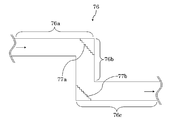
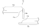
- FIG. 7 is a cross-sectional view showing the transfer path 76.
- the transfer path 76 includes a portion 76a (first portion) extending in the first direction, a portion 76b (second portion) extending in the second direction, and a portion 76c (third portion) extending in the third direction.
- the first direction is the horizontal direction
- the second direction is the vertical direction
- the third direction is the horizontal direction.
- the portion 76b is connected to the portion 76a downstream of the portion 76a.
- the portion 76c is connected to the portion 76b downstream of the portion 76b.
- the inner diameter of the transfer path 76 is, for example, not less than 10 cm and not more than 20 cm.
- a concave / convex surface 77a (first concave / convex surface) is present at the connecting portion between the portion 76a and the portion 76b.
- the uneven surface 77a is provided at a position where the sanitary article transferred through the portion 76a collides.
- the uneven surface 77a forms an angle of about 45 ° with respect to the vertical surface.
- a corrugated or embossed plate member can be used as the uneven surface 77a.
- the material of the uneven surface 77a is, for example, aluminum.
- a concave / convex surface 77b (second concave / convex surface) is present at the connecting portion between the portion 76b and the portion 76c.
- the uneven surface 77b is provided at a position where the sanitary product transferred through the portion 76b collides.
- the uneven surface 77b forms an angle of approximately 45 ° with respect to the horizontal plane.
- a corrugated or embossed plate member can be used as the uneven surface 77b.
- the material of the uneven surface 77b is, for example, aluminum.
- FIG. 8 is a cross-sectional view showing the transfer path 78.
- the transfer path 78 includes a portion 78a (first portion) extending in the first direction, a portion 78b (second portion) extending in the second direction, and a portion 78c (third portion) extending in the third direction.
- the first direction is the horizontal direction
- the second direction is the vertical direction
- the third direction is the horizontal direction.
- the portion 78b is connected to the portion 78a downstream of the portion 78a.
- the portion 78c is connected to the portion 78b downstream of the portion 78b.
- the inner diameter of the transfer path 78 is, for example, not less than 10 cm and not more than 20 cm.
- a concave / convex surface 79a (third concave / convex surface) exists at a connecting portion between the portion 78a and the portion 78b.
- the uneven surface 79a is provided at a position where the sanitary article transferred through the portion 78a collides.
- the uneven surface 79a forms an angle of approximately 45 ° with respect to the vertical surface.
- a corrugated or embossed plate member can be used as the uneven surface 79a.
- the material of the uneven surface 79a is, for example, aluminum.
- a concave / convex surface 79b (fourth concave / convex surface) is present at the connecting portion between the portion 78b and the portion 78c.
- the uneven surface 79b is provided at a position where the sanitary product transferred through the portion 78b collides.
- the uneven surface 79b forms an angle of approximately 45 ° with respect to the horizontal plane.
- a corrugated or embossed plate member can be used as the uneven surface 79b.
- the material of the uneven surface 79b is, for example, aluminum.
- FIG. 9 is a cross-sectional view showing the transfer path 80.
- the transfer path 80 includes a portion 80a (first portion) extending in the first direction, a portion 80b (second portion) extending in the second direction, and a portion 80c (third portion) extending in the third direction.
- the first direction is the horizontal direction
- the second direction is the vertical direction
- the third direction is the horizontal direction.
- the part 80b is connected to the part 80a downstream of the part 80a.
- the portion 80c is connected to the portion 80b downstream of the portion 80b.
- the inner diameter of the transfer path 80 is, for example, not less than 10 cm and not more than 20 cm.
- a concave / convex surface 81a (fifth concave / convex surface) is present at the connecting portion between the portion 80a and the portion 80b.
- the uneven surface 81a is provided at a position where the sanitary product transferred through the portion 80a collides.
- the uneven surface 81a forms an angle of about 45 ° with respect to the vertical surface.
- a corrugated or embossed plate-like member can be used as the uneven surface 81a.
- the material of the uneven surface 81a is, for example, aluminum.
- a concave / convex surface 81b (sixth concave / convex surface) is present at the connecting portion between the portion 80b and the portion 80c.
- the uneven surface 81b is provided at a position where the sanitary article transferred through the portion 80b collides.
- the uneven surface 81b forms an angle of approximately 45 ° with respect to the horizontal plane.
- a corrugated or embossed plate member can be used as the uneven surface 81b.
- the material of the uneven surface 81b is, for example, aluminum.
- the operation of the separation device 90 will be described.
- the sanitary article that is the object to be processed is first shredded by the shredder 30.
- the sanitary goods chopped by the chopping unit 30 are transferred to the separation unit 40 through the transfer path 76.
- the sanitary article transferred to the separation unit 40 is pushed out from the inlet side (left side in FIG. 3) of the drum 42 to the outlet side (right side in FIG. 3) by the rotating screw member 48. Meanwhile, fluff pulp and water-absorbing polymer dissociated from the plastic are discharged out of the drum 42 through the holes 42a due to centrifugal force generated by the rotation of the drum 42, and the like.
- the mixture of fluff pulp and water-absorbing polymer thus obtained can be used as a material for the coating layer portion 20.
- the fluff pulp and the water-absorbing polymer separated from the sanitary product by the separation unit 40 are transferred to the separation unit 92 through the transfer path 93.
- the fluff pulp and the water-absorbing polymer transferred to the separation unit 92 are separated from each other.
- the fluff pulp obtained in this way can be used as a material for the coating layer portion 20 or can be used as a material for the granular core portion 10. Further, the water-absorbing polymer thus obtained can be used as a material for the coating layer portion 20.
- the sanitary product after separation by the separation unit 40 is transferred to the shredding unit 50 through the transfer path 78 and further shredded.
- the sanitary product chopped by the chopping unit 50 is transferred to the separation unit 60 through the transfer path 80.
- the sanitary product transferred to the separation unit 60 is pushed out from the inlet side (left side in FIG. 5) of the drum 62 to the outlet side (right side in FIG. 5) by the rotating screw member 68. Meanwhile, the fluff pulp and the water-absorbing polymer dissociated from the plastic are discharged out of the drum 62 through the holes 62a due to the centrifugal force generated by the rotation of the drum 62 or the like.
- the mixture of fluff pulp and water-absorbing polymer thus obtained can be used as a material for the coating layer portion 20.
- the fluff pulp and the water-absorbing polymer separated from the sanitary goods by the separation unit 60 are transferred to the separation unit 94 through the transfer path 95.
- the fluff pulp and the water-absorbing polymer transferred to the separation unit 94 are separated from each other.
- the fluff pulp obtained in this way can be used as a material for the coating layer portion 20 or can be used as a material for the granular core portion 10. Further, the water-absorbing polymer thus obtained can be used as a material for the coating layer portion 20.
- This manufacturing method includes an acquisition process, a granulation process, a coating process, a sizing process, and a drying process.
- the acquisition step is a step of separating the water-absorbing polymer from the sanitary article and acquiring a water-absorbing material made of at least one of plastic and fluff pulp.
- the above-described separation device 90 is used. That is, in the acquisition process, first, the sanitary article is shredded by the shredder 30 (first shredding process). Next, in the separation unit 40, the fluff pulp and the water-absorbing polymer that have passed through the hole 42a are separated from the sanitary product by rotating the drum 42 in a state where the sanitary product shredded by the shredding unit 30 is accommodated. (First coarse separation step). Subsequently, the separation unit 92 separates the fluff pulp and the water-absorbing polymer separated from the sanitary article by the separation unit 40 (first fine separation step).
- the sanitary article from which the fluff pulp and the water-absorbing polymer are separated in the first rough separation step is further shredded by the shredder 50 (second shredding step).
- the drum 62 is rotated in a state where the sanitary product shredded by the shredding unit 50 is accommodated, so that the fluff pulp and the water-absorbing polymer that have passed through the hole 62a are separated from the sanitary product. (Second coarse separation step).
- the separation unit 94 separates the fluff pulp and the water-absorbing polymer separated from the sanitary product by the separation unit 60 (second fine separation step).
- the granulation step is a step of granulating the water-absorbing material acquired in the acquisition step.
- the core material containing the water-absorbing material the material constituting the granular core 10
- the core material is extruded and granulated by a granulator.
- core part material may be comprised only by the water absorbing material, and may be comprised by the mixture of water absorbing material and another material. Thereby, the granular core part 10 is obtained.
- the covering step is a step of covering the granulated product (granular core portion 10) granulated in the granulating step with a covering material (material constituting the covering layer portion 20).
- the coating material is attached to the surface of the granular core portion 10 using a coating apparatus or the like.
- the coating material can be applied, for example, by spraying or spraying. Thereby, the coating layer part 20 is obtained.
- the coating material contains fluff pulp and water-absorbing polymer separated from sanitary goods.
- the fluff pulp and the water-absorbing polymer used for the coating material may be separated from each other or may not be separated.
- the fluff pulp and the water-absorbing polymer separated from each other may be obtained in any one of the first fine separation step and the second fine separation step described above, or obtained in both steps. It may be. Further, the fluff pulp and the water-absorbing polymer that are not separated from each other may be obtained in any one of the first coarse separation step and the second coarse separation step described above, or obtained in both steps. It may be what was made.
- covering material may be comprised only by the fluff pulp and water-absorbing polymer isolate
- the coating step may include a crushing step of crushing the fluff pulp and the water-absorbing polymer contained in the coating material to a predetermined particle size.
- the fluff pulp is preferably pulverized to a particle size of less than 1 mm and the water-absorbing polymer is pulverized to a particle size of less than 35 ⁇ m.
- the pulverization step is provided, the fluff pulp and the water-absorbing polymer are separated from each other and then pulverized by a pulverizer or the like. And the coating layer part 20 is formed using the coating material containing the crushed fluff pulp and the water-absorbing polymer.
- the sizing step only the water-absorbing treatment material satisfying the predetermined standard is extracted by passing the water-absorbing treatment material produced in the previous step through a sieve having a sieve with a predetermined size.
- the water-absorbing treatment material extracted in the previous process is dried with a dryer.
- the moisture content of the granular core 10 it is possible to prevent moisture in the granular core 10 from transitioning to the coating layer 20 and deteriorating the water absorption performance, and to prevent mold and the like during storage of the water-absorbing treatment material 1. Can be prevented.
- the water absorption treatment material 1 is obtained.
- a water-absorbing material made of at least one of a plastic and fluff pulp obtained by separating a water-absorbing polymer from sanitary goods is used.
- a water absorption material can be acquired from the waste material of sanitary goods, the procurement cost of a material can be reduced and the manufacturing cost of the water absorption processing material 1 can also be reduced by extension.
- the water-absorbing material is used as a main material of the water-absorbing treatment material 1, the effect of reducing the procurement cost of the material becomes remarkable.
- the weight ratio of the water-absorbing polymer remaining in the water-absorbing material is only 3% or less, the quality of the water-absorbing treatment material 1 can be prevented from being deteriorated.
- the water-absorbing treatment material 1 that has absorbed water during use tends to collapse from the inside due to excessive swelling of the water-absorbing polymer.
- the water-absorbing treatment materials 1 are difficult to adhere to each other and block formation is hindered, and the amount of heat generated when the used water-absorbing treatment material 1 is incinerated is increased.
- the water-absorbing treatment material 1 has a multilayer structure composed of the granular core portion 10 and the coating layer portion 20, and the coating layer portion 20 contains fluff pulp and water-absorbing polymer separated from sanitary goods. Yes. Thereby, since the material of the coating layer part 20 can also be acquired from the waste material of sanitary goods, it contributes to the reduction of the procurement cost of material.
- the water-absorbing polymer contained in the coating layer portion 20 is pulverized to a particle size of less than 35 ⁇ m, the water-absorbing power of the water-absorbing polymer is reduced while the adhesive force is increased. Therefore, the agglomeration function of the coating layer portion 20 can be enhanced while suppressing the swelling of the water-absorbing polymer during use.
- the separation efficiency refers to the ratio of the weight of the second and third materials separated from the processing object to the weight of the second and third materials contained in the processing object immediately before the processing. .
- the drum 42 is provided with a protrusion 44.
- sanitary goods tend to gather at the lower part of the drum 42 due to the influence of gravity.
- the sanitary goods in the drum 42 are easily lifted by the protrusions 44, and thus easily reach the upper part of the drum 42.
- the sanitary article spreads over a wide area on the inner peripheral surface of the drum 42, so that separation by the separation unit 40 is promoted. Further, the impact when the sanitary article falls from the upper part of the drum 42 promotes the dissociation of the fluff pulp and the water-absorbing polymer from the plastic.
- the protrusion 44 becomes an obstacle when the sanitary product is pushed forward by the screw member 48, the time during which the sanitary product stays in the drum 42 becomes longer. Thereby, more fluff pulp and a water absorbing polymer can be isolate
- a screw member 48 is provided inside the drum 42.
- the sanitary goods in the drum 42 are hit by the screw member 48 or rubbed against the inner peripheral surface of the drum 42.
- the impact and friction force promote the dissociation of fluff pulp and water-absorbing polymer from the plastic.
- the protrusion 44 is provided, the sanitary article may be hit by the screw member 48 or rubbed against the inner peripheral surface of the drum 42 while being caught on the protrusion 44. In this case, since the force is difficult to escape, the impact and frictional force received by the sanitary article is increased, thereby further promoting the dissociation of the fluff pulp and the water-absorbing polymer from the plastic.
- the screw member 48 rotates with the side 49b having an obtuse angle instead of the side 49a having a substantially right angle with the rotation direction (tangential direction of the rotation rod 46) (see FIG. 4). Thereby, it can prevent that sanitary goods are caught on the tooth
- the drum 62 is provided with a protrusion 64.
- sanitary goods tend to gather at the lower part of the drum 62 due to the influence of gravity.
- the sanitary goods in the drum 62 are easily lifted by the protrusions 64, and thus easily reach the upper part of the drum 62.
- the sanitary article spreads over a wide range of the inner peripheral surface of the drum 62, and thus the separation by the separation unit 60 is promoted. Further, the impact of the sanitary article falling from the upper part of the drum 62 promotes the dissociation of the fluff pulp and the water-absorbing polymer from the plastic.
- the protrusion 64 becomes an obstacle when the sanitary product is pushed forward by the screw member 68, the time during which the sanitary product stays in the drum 62 becomes long. Thereby, more fluff pulp and a water absorbing polymer can be isolate
- a screw member 68 is provided inside the drum 62.
- the sanitary product in the drum 62 is hit by the screw member 68 or rubbed against the inner peripheral surface of the drum 62.
- the impact and friction force promote the dissociation of fluff pulp and water-absorbing polymer from the plastic.
- the protrusion 64 since the protrusion 64 is provided, the sanitary article may be hit by the screw member 68 or rubbed against the inner peripheral surface of the drum 62 while being caught on the protrusion 64. In this case, since the force is difficult to escape, the impact and frictional force received by the sanitary article is increased, thereby further promoting the dissociation of the fluff pulp and the water-absorbing polymer from the plastic.
- the screw member 68 rotates with the side 69b having an obtuse angle instead of the side 69a having a substantially right angle with the rotation direction (tangential direction of the rotary rod 66) (see FIG. 6). Thereby, it is possible to prevent the sanitary article from being excessively caught on the teeth 69 of the screw member 68.
- the transfer path 76 has a portion 76a and a portion 76b orthogonal to each other (see FIG. 7). Thereby, the sanitary goods transferred by the wind pressure collide with the inner surface of the transfer path 76 at the connecting portion between the portion 76a and the portion 76b. The impact promotes the dissociation of fluff pulp and water-absorbing polymer from the plastic. Further, the transfer path 76 has a portion 76c orthogonal to the portion 76b. As a result, the sanitary article transferred by the wind pressure collides with the inner surface of the transfer path 76 even at the connecting portion between the portion 76b and the portion 76c. The impact promotes the dissociation of fluff pulp and water-absorbing polymer from the plastic.
- An uneven surface 77a exists at the connecting portion between the portion 76a and the portion 76b.
- the sanitary article that collided with the uneven surface 77a receives a stronger impact than when the sanitary product collided with the flat surface. For this reason, dissociation of the fluff pulp and the water-absorbing polymer from the plastic is further promoted.
- a concavo-convex surface 77b exists at the connecting portion between the portion 76b and the portion 76c. The sanitary article that collided with the uneven surface 77b receives a stronger impact than when the sanitary product collided with the flat surface. For this reason, dissociation of the fluff pulp and the water-absorbing polymer from the plastic is further promoted.
- the transfer path 78 has a portion 78a and a portion 78b that are orthogonal to each other (see FIG. 8). Thereby, the sanitary goods transferred by the wind pressure collide with the inner surface of the transfer path 78 at the connecting portion between the portion 78a and the portion 78b. The impact promotes the dissociation of fluff pulp and water-absorbing polymer from the plastic. Further, the transfer path 78 has a portion 78c orthogonal to the portion 78b. Thereby, the sanitary goods transferred by the wind pressure collide with the inner surface of the transfer path 78 even at the connecting portion between the portion 78b and the portion 78c. The impact promotes the dissociation of fluff pulp and water-absorbing polymer from the plastic.
- An uneven surface 79a exists at the connecting portion between the portion 78a and the portion 78b.
- the sanitary product that has collided with the uneven surface 79a receives a stronger impact than when the sanitary product collided with the flat surface. For this reason, dissociation of the fluff pulp and the water-absorbing polymer from the plastic is further promoted.
- a concavo-convex surface 79b exists at the connecting portion between the portion 78b and the portion 78c. The sanitary article that collided with the uneven surface 79b receives a stronger impact than when the sanitary article collided with the flat surface. For this reason, dissociation of the fluff pulp and the water-absorbing polymer from the plastic is further promoted.
- the transfer path 80 has a portion 80a and a portion 80b that are orthogonal to each other (see FIG. 9). Thereby, the sanitary goods transferred by the wind pressure collide with the inner surface of the transfer path 80 at the connecting portion between the portion 80a and the portion 80b. The impact promotes the dissociation of fluff pulp and water-absorbing polymer from the plastic. Further, the transfer path 80 has a portion 80c orthogonal to the portion 80b. Thereby, the sanitary goods transferred by the wind pressure collide with the inner surface of the transfer path 80 even at the connecting portion between the portion 80b and the portion 80c. The impact promotes the dissociation of fluff pulp and water-absorbing polymer from the plastic.
- An uneven surface 81a is present at the connecting portion between the portion 80a and the portion 80b.
- the sanitary article that collided with the uneven surface 81a receives a stronger impact than when the sanitary product collided with the flat surface. For this reason, dissociation of the fluff pulp and the water-absorbing polymer from the plastic is further promoted.
- a concavo-convex surface 81b exists at the connecting portion between the portion 80b and the portion 80c. The sanitary article that collided with the uneven surface 81b receives a stronger impact than when the sanitary article collided with the flat surface. For this reason, dissociation of the fluff pulp and the water-absorbing polymer from the plastic is further promoted.
- the water-absorbing treatment material and the manufacturing method thereof according to the present invention are not limited to the above embodiment, and various modifications are possible.
- the water absorbing material showed the example which is the main material of the water absorption processing material 1.
- FIG. However, as long as the water-absorbing material is included in the water-absorbing treatment material 1, it is not essential that the water-absorbing material is included as a main material.
- the water-absorbing treatment material 1 has a multilayer structure including the granular core portion 10 and the coating layer portion 20 has been described.
- the water-absorbing treatment material 1 may have a single layer structure including the granular core portion 10.
- shredding and rough separation are performed twice.
- shredding and rough separation may be performed once or three or more times.
- drum 42 is cylindrical
- the drum 42 may be tapered.
- the central axis of the drum 42 is horizontal is shown.
- the central axis of the drum 42 may be inclined downward from the inlet side toward the outlet side. The same applies to the drum 62.
- the hole 42a is formed over substantially the entire drum 42.
- the hole 42a may be formed only in a part of the drum 42.
- the hole 42a may be formed by forming substantially the whole or a part of the drum 42 into a net shape. That is, in this case, the mesh of the drum 42 corresponds to the hole 42a.
- the hole 62a The same applies to the hole 62a.
- the protrusion 44 extends over substantially the entire path from the inlet side to the outlet side of the drum 42 is shown.
- the protrusion 44 may extend only in a part of the path from the inlet side to the outlet side of the drum 42.
- the ridge 44 having a substantially triangular cross section is illustrated.
- the protrusion 44 may have a flat plate shape as shown in FIG. The same applies to the ridges 64.
- the number of the protrusions 44 can be an arbitrary number of 1 or more.
- the uneven surface 77a forms a certain angle with respect to the vertical surface is shown.
- the uneven surface 77a may be along a vertical surface as shown in FIG.
- the uneven surface 77a may be provided with a protrusion P1 on the inner surface of the transfer path 76 (position where the sanitary product transferred through the portion 76a collides).
- the number of the protrusions P1 may be one, or two or more. The same applies to the uneven surface 79a and the uneven surface 81a.
- the uneven surface 77b may be along a horizontal plane as shown in FIG.
- the uneven surface 77b may be provided with a protrusion P2 on the inner surface of the transfer path 76 (a position where the sanitary article transferred through the portion 76b collides).
- the number of protrusions P2 may be one, or two or more. The same applies to the uneven surface 79b and the uneven surface 81b.
- the transfer path 76 is configured by a plurality of portions orthogonal to each other (see FIG. 7).
- the transfer path 76 may be a straight duct.
- the transfer path 78 and the transfer path 80 may be a straight duct.
- the separation device 90 is provided with the separation unit 92 and the separation unit 94 .
- plastic is used as the water absorbing material among plastic and fluff pulp, it is not essential to provide the separation portion 92 and the separation portion 94.
- the water absorption treatment material is a granular excrement treatment material
- the water-absorbing treatment material according to the present invention may be any material that absorbs liquid, and may be, for example, a pet sheet, a water-stopping material, a liquid-absorbing sheet, or the like.
Landscapes
- Chemical & Material Sciences (AREA)
- Analytical Chemistry (AREA)
- Organic Chemistry (AREA)
- Chemical Kinetics & Catalysis (AREA)
- Life Sciences & Earth Sciences (AREA)
- Environmental Sciences (AREA)
- Engineering & Computer Science (AREA)
- Animal Husbandry (AREA)
- Biodiversity & Conservation Biology (AREA)
- Zoology (AREA)
- Environmental & Geological Engineering (AREA)
- Mechanical Engineering (AREA)
- Absorbent Articles And Supports Therefor (AREA)
- Solid-Sorbent Or Filter-Aiding Compositions (AREA)
- Combined Means For Separation Of Solids (AREA)
- Separation, Recovery Or Treatment Of Waste Materials Containing Plastics (AREA)
- Processing Of Solid Wastes (AREA)
Abstract
Description
10 粒状芯部
20 被覆層部
30 細断部(第1の細断部)
40 分離部(第1の粗分離部)
42 ドラム(第1の筒状部)
42a 孔(第1の孔)
44 突条(第1の突条)
46 回転ロッド
48 スクリュー部材
49 歯
50 細断部(第2の細断部)
60 分離部(第2の粗分離部)
62 ドラム(第2の筒状部)
62a 孔(第2の孔)
64 突条(第2の突条)
66 回転ロッド
68 スクリュー部材
69 歯
76 移送路(第1の通風管)
77a 凹凸面(第1の凹凸面)
77b 凹凸面(第2の凹凸面)
78 移送路(第2の通風管)
79a 凹凸面(第3の凹凸面)
79b 凹凸面(第4の凹凸面)
80 移送路(第3の通風管)
81a 凹凸面(第5の凹凸面)
81b 凹凸面(第6の凹凸面)
90 分離装置
92 分離部(第1の細分離部)
93 移送路
94 分離部(第2の細分離部)
95 移送路
Claims (36)
- プラスチック、フラッフパルプ及び吸水性ポリマーを含む衛生用品から前記吸水性ポリマーを分離して得られた前記プラスチック及び前記フラッフパルプのうち少なくとも一方からなる吸水材料を含有し、
前記吸水材料に付着している前記吸水性ポリマーの当該吸水材料に対する重量割合は、3%以下であることを特徴とする吸水処理材。 - 請求項1に記載の吸水処理材において、
前記吸水性ポリマーは、分離装置により、前記衛生用品から分離され、
前記分離装置は、
前記衛生用品を細断する第1の細断部と、
前記第1の細断部によって細断された前記衛生用品に含まれる前記プラスチックを通過させずに前記フラッフパルプ及び前記吸水性ポリマーを通過させる多数の第1の孔が形成された第1の筒状部を有し、前記第1の細断部によって細断された前記衛生用品が収容された状態で前記第1の筒状部を回転させることにより、当該衛生用品から前記第1の孔を通過した、前記フラッフパルプ及び前記吸水性ポリマーを分離する第1の粗分離部と、
を有する吸水処理材。 - 請求項2に記載の吸水処理材において、
前記分離装置は、
前記第1の粗分離部によって前記衛生用品から分離された前記フラッフパルプ及び前記吸水性ポリマーを互いに分離する第1の細分離部を有する吸水処理材。 - 請求項2又は3に記載の吸水処理材において、
前記分離装置は、
前記第1の筒状部の内周面上に設けられ、当該第1の筒状部の中心軸方向に延在する第1の突条を有する吸水処理材。 - 請求項4に記載の吸水処理材において、
前記第1の突条はp本(p:3以上5以下の整数)存在し、当該p本の第1の突条は、前記第1の筒状部の前記内周面上に等間隔で配設されている吸水処理材。 - 請求項2乃至5の何れかに記載の吸水処理材において、
前記分離装置は、
前記第1の細断部によって細断された前記衛生用品を、風圧によって前記第1の粗分離部に向けて移送するための第1の通風管を有し、
前記第1の通風管は、第1の方向に延びる第1の部分と、前記第1の部分の下流において当該第1の部分に連結され、前記第1の方向と略直交する第2の方向に延びる第2の部分とを有する吸水処理材。 - 請求項6に記載の吸水処理材において、
前記分離装置は、
前記第1の通風管における前記第1の部分と前記第2の部分との連結部分に存在し、前記第1の部分を通って移送されてきた前記衛生用品が衝突する第1の凹凸面を有する吸水処理材。 - 請求項6又は7に記載の吸水処理材において、
前記第1の通風管は、前記第2の部分の下流において当該第2の部分に連結され、前記第2の方向と略直交する第3の方向に延びる第3の部分を有する吸水処理材。 - 請求項8に記載の吸水処理材において、
前記分離装置は、
前記第1の通風管における前記第2の部分と前記第3の部分との連結部分に存在し、前記第2の部分を通って移送されてきた前記衛生用品が衝突する第2の凹凸面を有する吸水処理材。 - 請求項2乃至9の何れかに記載の吸水処理材において、
前記分離装置は、
前記第1の粗分離部によって前記第1の孔を通過した前記フラッフパルプ及び前記吸水性ポリマーが分離された前記衛生用品を、風圧によって移送するための第2の通風管を有し、
前記第2の通風管は、第1の方向に延びる第1の部分と、前記第1の部分の下流において当該第1の部分に連結され、前記第1の方向と略直交する第2の方向に延びる第2の部分とを有する吸水処理材。 - 請求項10に記載の吸水処理材において、
前記分離装置は、
前記第2の通風管における前記第1の部分と前記第2の部分との連結部分に存在し、前記第1の部分を通って移送されてきた前記衛生用品が衝突する第3の凹凸面を有する吸水処理材。 - 請求項10又は11に記載の吸水処理材において、
前記第2の通風管は、前記第2の部分の下流において当該第2の部分に連結され、前記第2の方向と略直交する第3の方向に延びる第3の部分を有する吸水処理材。 - 請求項12に記載の吸水処理材において、
前記分離装置は、
前記第2の通風管における前記第2の部分と前記第3の部分との連結部分に存在し、前記第2の部分を通って移送されてきた前記衛生用品が衝突する第4の凹凸面を有する吸水処理材。 - 請求項2乃至13の何れかに記載の吸水処理材において、
前記分離装置は、
前記第1の粗分離部によって前記第1の孔を通過した前記フラッフパルプ及び前記吸水性ポリマーが分離された前記衛生用品を細断する第2の細断部と、
前記第2の細断部によって細断された前記衛生用品に含まれる前記プラスチックを通過させずに前記フラッフパルプ及び前記吸水性ポリマーを通過させる多数の第2の孔が形成された第2の筒状部を有し、前記第2の細断部によって細断された前記衛生用品が収容された状態で前記第2の筒状部を回転させることにより、当該衛生用品から前記第2の孔を通過した前記フラッフパルプ及び前記吸水性ポリマーを分離する第2の粗分離部と、
を有する吸水処理材。 - 請求項14に記載の吸水処理材において、
前記分離装置は、
前記第2の粗分離部によって前記衛生用品から分離された前記フラッフパルプ及び前記吸水性ポリマーを互いに分離する第2の細分離部を有する吸水処理材。 - 請求項14又は15に記載の吸水処理材において、
前記第2の孔の平面視での面積は、前記第1の孔の平面視での面積よりも小さい吸水処理材。 - 請求項14乃至16の何れかに記載の吸水処理材において、
前記分離装置は、
前記第2の筒状部の内周面上に設けられ、当該第2の筒状部の中心軸方向に延在する第2の突条を有する吸水処理材。 - 請求項17に記載の吸水処理材において、
前記第2の突条はq本(q:3以上5以下の整数)存在し、当該q本の第2の突条は、前記第2の筒状部の前記内周面上に等間隔で配設されている吸水処理材。 - 請求項14乃至18の何れかに記載の吸水処理材において、
前記分離装置は、
前記第2の細断部によって細断された前記衛生用品を、風圧によって前記第2の粗分離部に向けて移送するための第3の通風管を有し、
前記第3の通風管は、第1の方向に延びる第1の部分と、前記第1の部分の下流において当該第1の部分に連結され、前記第1の方向と略直交する第2の方向に延びる第2の部分とを有する吸水処理材。 - 請求項19に記載の吸水処理材において、
前記分離装置は、
前記第3の通風管における前記第1の部分と前記第2の部分との連結部分に存在し、前記第1の部分を通って移送されてきた前記衛生用品が衝突する第5の凹凸面を有する吸水処理材。 - 請求項19又は20に記載の吸水処理材において、
前記第3の通風管は、前記第2の部分の下流において当該第2の部分に連結され、前記第2の方向と略直交する第3の方向に延びる第3の部分を有する吸水処理材。 - 請求項21に記載の吸水処理材において、
前記第3の通風管における前記第2の部分と前記第3の部分との連結部分に存在し、前記第2の部分を通って移送されてきた前記衛生用品が衝突する第6の凹凸面を有する吸水処理材。 - 請求項1乃至22の何れかに記載の吸水処理材において、
前記吸水材料を含有する粒状芯部と、
前記粒状芯部を覆う被覆層部と、
を備える吸水処理材。 - 請求項23に記載の吸水処理材において、
前記被覆層部は、前記フラッフパルプ及び前記吸水性ポリマーを含有する吸水処理材。 - 請求項24に記載の吸水処理材において、
前記被覆層部に含有される前記フラッフパルプ及び前記吸水性ポリマーは、それぞれ所定の粒度に粉砕されたものである吸水処理材。 - 請求項25に記載の吸水処理材において、
前記被覆層部に含有される前記吸水性ポリマーは、35μm未満の粒度に粉砕されたものである吸水処理材。 - 請求項1乃至26の何れかに記載の吸水処理材において、
前記吸水材料は、当該吸水処理材の主材料である吸水処理材。 - プラスチック、フラッフパルプ及び吸水性ポリマーを含む衛生用品から前記吸水性ポリマーを分離して、前記プラスチック及び前記フラッフパルプのうち少なくとも一方からなる吸水材料を取得する取得工程と、
前記取得工程において取得された前記吸水材料を造粒する造粒工程と、を含み、
前記取得工程においては、前記吸水材料に付着している前記吸水性ポリマーの当該吸水材料に対する重量割合が3%以下となるように、前記衛生用品から前記吸水性ポリマーを分離することを特徴とする吸水処理材の製造方法。 - 請求項28に記載の吸水処理材の製造方法において、
前記取得工程は、
前記衛生用品を細断する第1の細断工程と、
前記第1の細断工程において細断された前記衛生用品に含まれる前記プラスチックを通過させずに前記フラッフパルプ及び前記吸水性ポリマーを通過させる多数の第1の孔が形成された第1の筒状部に、前記第1の細断工程において細断された前記衛生用品を収容した状態で前記第1の筒状部を回転させることにより、当該衛生用品から前記第1の孔を通過した前記フラッフパルプ及び前記吸水性ポリマーを分離する第1の粗分離工程と、
を含む吸水処理材の製造方法。 - 請求項29に記載の吸水処理材の製造方法において、
前記取得工程は、
前記第1の粗分離工程において前記衛生用品から分離された前記フラッフパルプ及び前記吸水性ポリマーを互いに分離する第1の細分離工程を含む吸水処理材の製造方法。 - 請求項29又は30に記載の吸水処理材の製造方法において、
前記取得工程は、
前記第1の粗分離工程において前記第1の孔を通過した前記フラッフパルプ及び前記吸水性ポリマーが分離された前記衛生用品を細断する第2の細断工程と、
前記第2の細断工程において細断された前記衛生用品に含まれる前記プラスチックを通過させずに前記フラッフパルプ及び前記吸水性ポリマーを通過させる多数の第2の孔が形成された第2の筒状部に、前記第2の細断工程において細断された前記衛生用品を収容した状態で前記第2の筒状部を回転させることにより、当該衛生用品から前記第2の孔を通過した前記フラッフパルプ及び前記吸水性ポリマーを分離する第2の粗分離工程と、
を含む吸水処理材の製造方法。 - 請求項31に記載の吸水処理材の製造方法において、
前記取得工程は、
前記第2の粗分離工程において前記衛生用品から分離された前記フラッフパルプ及び前記吸水性ポリマーを互いに分離する第2の細分離工程を含む吸水処理材の製造方法。 - 請求項28乃至32の何れかに記載の吸水処理材の製造方法において、
前記造粒工程において造粒された造粒物を被覆材料で被覆する被覆工程を含む吸水処理材の製造方法。 - 請求項33に記載の吸水処理材の製造方法において、
前記被覆材料は、前記フラッフパルプ及び前記吸水性ポリマーを含有する吸水処理材の製造方法。 - 請求項34に記載の吸水処理材の製造方法において、
前記被覆工程は、
前記被覆材料に含有される前記フラッフパルプ及び前記吸水性ポリマーをそれぞれ所定の粒度に粉砕する粉砕工程を含む吸水処理材の製造方法。 - 請求項35に記載の吸水処理材の製造方法において、
前記粉砕工程においては、前記吸水性ポリマーを35μm未満の粒度に粉砕する吸水処理材の製造方法。
Priority Applications (6)
| Application Number | Priority Date | Filing Date | Title |
|---|---|---|---|
| PCT/JP2013/063180 WO2014181469A1 (ja) | 2013-05-10 | 2013-05-10 | 吸水処理材及びその製造方法 |
| EP13883944.4A EP2995372A4 (en) | 2013-05-10 | 2013-05-10 | Water-absorbent treatment material and manufacturing method thereof |
| JP2015515757A JP6248100B2 (ja) | 2013-05-10 | 2013-05-10 | 吸水処理材及びその製造方法 |
| HK16103351.9A HK1215414B (zh) | 2013-05-10 | 吸水处理材料及其制造方法 | |
| CN201380076447.0A CN105188912B (zh) | 2013-05-10 | 2013-05-10 | 吸水处理材料及其制造方法 |
| US14/833,697 US9393546B2 (en) | 2013-05-10 | 2015-08-24 | Water absorbing material and manufacturing method thereof |
Applications Claiming Priority (1)
| Application Number | Priority Date | Filing Date | Title |
|---|---|---|---|
| PCT/JP2013/063180 WO2014181469A1 (ja) | 2013-05-10 | 2013-05-10 | 吸水処理材及びその製造方法 |
Related Child Applications (1)
| Application Number | Title | Priority Date | Filing Date |
|---|---|---|---|
| US14/833,697 Continuation US9393546B2 (en) | 2013-05-10 | 2015-08-24 | Water absorbing material and manufacturing method thereof |
Publications (1)
| Publication Number | Publication Date |
|---|---|
| WO2014181469A1 true WO2014181469A1 (ja) | 2014-11-13 |
Family
ID=51866969
Family Applications (1)
| Application Number | Title | Priority Date | Filing Date |
|---|---|---|---|
| PCT/JP2013/063180 Ceased WO2014181469A1 (ja) | 2013-05-10 | 2013-05-10 | 吸水処理材及びその製造方法 |
Country Status (5)
| Country | Link |
|---|---|
| US (1) | US9393546B2 (ja) |
| EP (1) | EP2995372A4 (ja) |
| JP (1) | JP6248100B2 (ja) |
| CN (1) | CN105188912B (ja) |
| WO (1) | WO2014181469A1 (ja) |
Cited By (8)
| Publication number | Priority date | Publication date | Assignee | Title |
|---|---|---|---|---|
| JP2016131956A (ja) * | 2015-01-22 | 2016-07-25 | 株式会社大貴 | 分離装置、及び吸水処理材の製造方法 |
| JP2016137430A (ja) * | 2015-01-27 | 2016-08-04 | 株式会社大貴 | 分離装置、及び吸水処理材の製造方法 |
| JP2016140830A (ja) * | 2015-02-03 | 2016-08-08 | 株式会社大貴 | 分離装置、及び吸水処理材の製造方法 |
| JP2016140831A (ja) * | 2015-02-03 | 2016-08-08 | 株式会社大貴 | 分離装置、及び吸水処理材の製造方法 |
| WO2017104062A1 (ja) * | 2015-12-18 | 2017-06-22 | 株式会社無有 | 分離装置、及び吸水処理材の製造方法 |
| JP6352563B1 (ja) * | 2018-01-22 | 2018-07-04 | 株式会社大貴 | 生ゴミ処理材及びその製造方法、並びに生ゴミの処理方法 |
| WO2019244488A1 (ja) * | 2018-06-21 | 2019-12-26 | 株式会社大貴 | 吸水処理材の製造方法 |
| JP2022015988A (ja) * | 2020-07-10 | 2022-01-21 | 株式会社辰巳エヤーエンジニアリング | 分離装置 |
Families Citing this family (10)
| Publication number | Priority date | Publication date | Assignee | Title |
|---|---|---|---|---|
| EP3412143B1 (en) * | 2016-02-01 | 2020-08-12 | Daiki Co., Ltd. | Method for making a water-absorbing treatment material |
| US10655330B2 (en) | 2016-04-29 | 2020-05-19 | Yair Y. KESHET | Modular stormwater management device and system |
| IT201600097297A1 (it) * | 2016-09-28 | 2018-03-28 | Fater Spa | Procedimento e apparecchiatura per separare plastica e cellulosa da prodotti sanitari assorbenti post-consumo |
| CN107455269A (zh) * | 2017-08-30 | 2017-12-12 | 杭州可靠护理用品股份有限公司 | 一种宠物排泄物吸收用品的制备方法 |
| JP6667575B2 (ja) * | 2017-11-01 | 2020-03-18 | ユニ・チャーム株式会社 | 有機酸の回収方法、及びリサイクルパルプの製造方法 |
| CN108887183A (zh) * | 2018-08-01 | 2018-11-27 | 孟健 | 一种卫生材料宠物垫料及其制备方法 |
| CN109601404A (zh) * | 2018-11-27 | 2019-04-12 | 山东海沃世丰农业科技有限公司 | 一种动物卫生砂及其制备方法 |
| CZ33689U1 (cs) * | 2019-12-23 | 2020-02-04 | Tommi CZ s.r.o. | Podestýlka pro malá zvířata |
| CN118475744A (zh) * | 2021-09-17 | 2024-08-09 | 益钧环保科技股份有限公司 | 吸水原料处理系统及其运作方法 |
| CN116748265A (zh) * | 2023-06-19 | 2023-09-15 | 上海青浦淇华塑料科技有限公司 | 一种高分子吸水颗粒的筛选提取方法和应用 |
Citations (4)
| Publication number | Priority date | Publication date | Assignee | Title |
|---|---|---|---|---|
| JP2003039023A (ja) * | 2001-07-31 | 2003-02-12 | Daiki:Kk | 汚れが付着している衛生用品からのその素材の回収方法 |
| JP2003200147A (ja) * | 2001-12-28 | 2003-07-15 | Daiki:Kk | 汚れが付着している衛生用品からのその素材の回収方法 |
| JP2003219746A (ja) * | 2002-01-30 | 2003-08-05 | Daiki:Kk | 粒状の汚物処理材の製造方法 |
| JP2006333773A (ja) | 2005-06-01 | 2006-12-14 | Daiki:Kk | 粒状の排泄物処理材 |
Family Cites Families (16)
| Publication number | Priority date | Publication date | Assignee | Title |
|---|---|---|---|---|
| US2721035A (en) * | 1952-09-15 | 1955-10-18 | Frank E Lankford | Apparatus for separating steel from slag |
| JPS56159232A (en) * | 1980-05-12 | 1981-12-08 | Kuraray Co Ltd | Powdery high water-absorption resin for surface coating |
| BR8707875A (pt) * | 1986-11-14 | 1989-10-03 | Ankal Pty Ltd | Aparelho para classificar material fibroso |
| JP3005132B2 (ja) * | 1993-01-29 | 2000-01-31 | キヤノン株式会社 | トナーの製造方法及びそのための製造装置システム |
| JPH0734899B2 (ja) * | 1993-03-31 | 1995-04-19 | 豊田通商株式会社 | 非鉄材料選別装置 |
| JP3566760B2 (ja) * | 1994-10-20 | 2004-09-15 | 林太郎 薦田 | 紙おむつ等の不良品から有価物を分離回収する分離装置および分離方法 |
| JP2000350944A (ja) * | 1999-06-10 | 2000-12-19 | Mitsubishi Chemicals Corp | 熱可塑性樹脂組成物の粉砕分級方法 |
| JP2003134953A (ja) * | 2001-11-05 | 2003-05-13 | Daiki:Kk | 粒状の排泄物処理材及び製造方法 |
| JP2004321332A (ja) * | 2003-04-22 | 2004-11-18 | Kohjin Co Ltd | 消臭機能を有する材料及びその製造方法 |
| RU2498854C2 (ru) * | 2008-07-02 | 2013-11-20 | Бюлер Аг | Способ получения муки из зерна, вальцовая мельница, применение вальцовой мельницы, зигзагообразная просеивающая машина, применение зигзагообразной просеивающей машины |
| CN101402098B (zh) * | 2008-10-30 | 2010-10-13 | 杭州新余宏机械有限公司 | 卫生用品废料回收系统及废料回收方法 |
| JP5326134B2 (ja) * | 2008-11-29 | 2013-10-30 | 博 伊藤 | 粒状の排泄物処理材及び製造方法 |
| JP4859946B2 (ja) * | 2009-04-10 | 2012-01-25 | 株式会社大貴 | 吸水処理材及びその製造方法 |
| JP5596957B2 (ja) * | 2009-08-13 | 2014-09-24 | 伊藤 博 | 吸水処理材 |
| EP2686118A1 (en) * | 2011-03-14 | 2014-01-22 | Sitec Castellarano S.p.A. | Process for handling waste material |
| CN102225415A (zh) * | 2011-03-31 | 2011-10-26 | 广州市万绿达集团有限公司 | 报废一次性卫生用品的回收处理方法 |
-
2013
- 2013-05-10 EP EP13883944.4A patent/EP2995372A4/en not_active Ceased
- 2013-05-10 CN CN201380076447.0A patent/CN105188912B/zh active Active
- 2013-05-10 JP JP2015515757A patent/JP6248100B2/ja active Active
- 2013-05-10 WO PCT/JP2013/063180 patent/WO2014181469A1/ja not_active Ceased
-
2015
- 2015-08-24 US US14/833,697 patent/US9393546B2/en active Active
Patent Citations (4)
| Publication number | Priority date | Publication date | Assignee | Title |
|---|---|---|---|---|
| JP2003039023A (ja) * | 2001-07-31 | 2003-02-12 | Daiki:Kk | 汚れが付着している衛生用品からのその素材の回収方法 |
| JP2003200147A (ja) * | 2001-12-28 | 2003-07-15 | Daiki:Kk | 汚れが付着している衛生用品からのその素材の回収方法 |
| JP2003219746A (ja) * | 2002-01-30 | 2003-08-05 | Daiki:Kk | 粒状の汚物処理材の製造方法 |
| JP2006333773A (ja) | 2005-06-01 | 2006-12-14 | Daiki:Kk | 粒状の排泄物処理材 |
Non-Patent Citations (1)
| Title |
|---|
| See also references of EP2995372A4 * |
Cited By (18)
| Publication number | Priority date | Publication date | Assignee | Title |
|---|---|---|---|---|
| EP3248694A4 (en) * | 2015-01-22 | 2018-05-23 | Daiki Co. Ltd. | Separating apparatus and method for manufacturing water absorption material |
| WO2016117145A1 (ja) * | 2015-01-22 | 2016-07-28 | 株式会社大貴 | 分離装置、及び吸水処理材の製造方法 |
| US10124371B2 (en) | 2015-01-22 | 2018-11-13 | Daiki Co., Ltd. | Separation device and method for manufacturing water absorption material |
| JP2016131956A (ja) * | 2015-01-22 | 2016-07-25 | 株式会社大貴 | 分離装置、及び吸水処理材の製造方法 |
| JP2016137430A (ja) * | 2015-01-27 | 2016-08-04 | 株式会社大貴 | 分離装置、及び吸水処理材の製造方法 |
| JP2016140831A (ja) * | 2015-02-03 | 2016-08-08 | 株式会社大貴 | 分離装置、及び吸水処理材の製造方法 |
| WO2016125322A1 (ja) * | 2015-02-03 | 2016-08-11 | 株式会社大貴 | 分離装置、及び吸水処理材の製造方法 |
| JP2016140830A (ja) * | 2015-02-03 | 2016-08-08 | 株式会社大貴 | 分離装置、及び吸水処理材の製造方法 |
| US10549454B2 (en) | 2015-02-03 | 2020-02-04 | Daiki Co., Ltd. | Separation device and method for manufacturing water absorption material |
| WO2017104062A1 (ja) * | 2015-12-18 | 2017-06-22 | 株式会社無有 | 分離装置、及び吸水処理材の製造方法 |
| JPWO2017104062A1 (ja) * | 2015-12-18 | 2017-12-21 | 株式会社無有 | 分離装置、及び吸水処理材の製造方法 |
| JP6352563B1 (ja) * | 2018-01-22 | 2018-07-04 | 株式会社大貴 | 生ゴミ処理材及びその製造方法、並びに生ゴミの処理方法 |
| WO2019142465A1 (ja) * | 2018-01-22 | 2019-07-25 | 株式会社大貴 | 生ゴミ処理材及びその製造方法、並びに生ゴミの処理方法 |
| JP2019126752A (ja) * | 2018-01-22 | 2019-08-01 | 株式会社大貴 | 生ゴミ処理材及びその製造方法、並びに生ゴミの処理方法 |
| US11712722B2 (en) | 2018-01-22 | 2023-08-01 | Daiki Co., Ltd. | Kitchen garbage treatment material and method for manufacturing the same, and kitchen garbage treatment method |
| WO2019244488A1 (ja) * | 2018-06-21 | 2019-12-26 | 株式会社大貴 | 吸水処理材の製造方法 |
| JP2022015988A (ja) * | 2020-07-10 | 2022-01-21 | 株式会社辰巳エヤーエンジニアリング | 分離装置 |
| JP7496605B2 (ja) | 2020-07-10 | 2024-06-07 | 株式会社辰巳エヤーエンジニアリング | 分離装置 |
Also Published As
| Publication number | Publication date |
|---|---|
| US20150360200A1 (en) | 2015-12-17 |
| US9393546B2 (en) | 2016-07-19 |
| JPWO2014181469A1 (ja) | 2017-02-23 |
| HK1215414A1 (zh) | 2016-08-26 |
| JP6248100B2 (ja) | 2017-12-13 |
| EP2995372A1 (en) | 2016-03-16 |
| CN105188912A (zh) | 2015-12-23 |
| EP2995372A4 (en) | 2017-01-04 |
| CN105188912B (zh) | 2018-09-07 |
Similar Documents
| Publication | Publication Date | Title |
|---|---|---|
| JP6248100B2 (ja) | 吸水処理材及びその製造方法 | |
| JP6193977B2 (ja) | 吸水処理材及びその製造方法 | |
| US10124371B2 (en) | Separation device and method for manufacturing water absorption material | |
| WO2014125613A1 (ja) | 分離装置及び分離方法 | |
| JP6248099B2 (ja) | 吸水処理材及びその製造方法 | |
| WO2014125615A1 (ja) | 分離装置 | |
| JPWO2017104062A1 (ja) | 分離装置、及び吸水処理材の製造方法 | |
| CN107107117B (zh) | 分离装置以及吸水处理材的制造方法 | |
| WO2014125614A1 (ja) | 分離装置 | |
| JP6352278B2 (ja) | 吸水処理材及びその製造方法 | |
| HK1215414B (zh) | 吸水处理材料及其制造方法 | |
| HK1215413B (zh) | 吸水处理材料及其制造方法 | |
| HK1212283B (zh) | 吸水处理材料及其制造方法 | |
| HK1236884A1 (en) | Separating apparatus and method for manufacturing water absorption material |
Legal Events
| Date | Code | Title | Description |
|---|---|---|---|
| WWE | Wipo information: entry into national phase |
Ref document number: 201380076447.0 Country of ref document: CN |
|
| 121 | Ep: the epo has been informed by wipo that ep was designated in this application |
Ref document number: 13883944 Country of ref document: EP Kind code of ref document: A1 |
|
| ENP | Entry into the national phase |
Ref document number: 2015515757 Country of ref document: JP Kind code of ref document: A |
|
| WWE | Wipo information: entry into national phase |
Ref document number: 2013883944 Country of ref document: EP |
|
| NENP | Non-entry into the national phase |
Ref country code: DE |