WO2014181497A1 - トランス - Google Patents
トランス Download PDFInfo
- Publication number
- WO2014181497A1 WO2014181497A1 PCT/JP2014/001987 JP2014001987W WO2014181497A1 WO 2014181497 A1 WO2014181497 A1 WO 2014181497A1 JP 2014001987 W JP2014001987 W JP 2014001987W WO 2014181497 A1 WO2014181497 A1 WO 2014181497A1
- Authority
- WO
- WIPO (PCT)
- Prior art keywords
- coil
- bobbin
- transformer
- voltage coil
- outer periphery
- Prior art date
- Legal status (The legal status is an assumption and is not a legal conclusion. Google has not performed a legal analysis and makes no representation as to the accuracy of the status listed.)
- Ceased
Links
Images


Classifications
-
- H—ELECTRICITY
- H01—ELECTRIC ELEMENTS
- H01F—MAGNETS; INDUCTANCES; TRANSFORMERS; SELECTION OF MATERIALS FOR THEIR MAGNETIC PROPERTIES
- H01F27/00—Details of transformers or inductances, in general
- H01F27/28—Coils; Windings; Conductive connections
- H01F27/32—Insulating of coils, windings, or parts thereof
- H01F27/324—Insulation between coil and core, between different winding sections, around the coil; Other insulation structures
- H01F27/325—Coil bobbins
-
- H—ELECTRICITY
- H01—ELECTRIC ELEMENTS
- H01F—MAGNETS; INDUCTANCES; TRANSFORMERS; SELECTION OF MATERIALS FOR THEIR MAGNETIC PROPERTIES
- H01F27/00—Details of transformers or inductances, in general
- H01F27/28—Coils; Windings; Conductive connections
- H01F27/2823—Wires
-
- H—ELECTRICITY
- H01—ELECTRIC ELEMENTS
- H01F—MAGNETS; INDUCTANCES; TRANSFORMERS; SELECTION OF MATERIALS FOR THEIR MAGNETIC PROPERTIES
- H01F27/00—Details of transformers or inductances, in general
- H01F27/28—Coils; Windings; Conductive connections
- H01F27/2866—Combination of wires and sheets
-
- H—ELECTRICITY
- H01—ELECTRIC ELEMENTS
- H01F—MAGNETS; INDUCTANCES; TRANSFORMERS; SELECTION OF MATERIALS FOR THEIR MAGNETIC PROPERTIES
- H01F27/00—Details of transformers or inductances, in general
- H01F27/28—Coils; Windings; Conductive connections
- H01F27/2871—Pancake coils
-
- H—ELECTRICITY
- H01—ELECTRIC ELEMENTS
- H01F—MAGNETS; INDUCTANCES; TRANSFORMERS; SELECTION OF MATERIALS FOR THEIR MAGNETIC PROPERTIES
- H01F5/00—Coils
- H01F5/02—Coils wound on non-magnetic supports, e.g. formers
- H01F2005/022—Coils wound on non-magnetic supports, e.g. formers wound on formers with several winding chambers separated by flanges, e.g. for high voltage applications
-
- H—ELECTRICITY
- H01—ELECTRIC ELEMENTS
- H01F—MAGNETS; INDUCTANCES; TRANSFORMERS; SELECTION OF MATERIALS FOR THEIR MAGNETIC PROPERTIES
- H01F5/00—Coils
- H01F5/02—Coils wound on non-magnetic supports, e.g. formers
- H01F2005/025—Coils wound on non-magnetic supports, e.g. formers wound on coaxial arrangement of two or more formers
Definitions
- the present invention relates to a transformer having a configuration suitable for use in a large current specification such as a switching power supply.
- Patent Document 1 proposes a transformer that uses edge-wise winding of a rectangular copper wire having a large cross-sectional area as a high-voltage coil and a low-voltage coil.
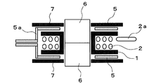
- FIG. 3 shows a transformer of this type, in which a stranded wire is wound around a bobbin 1 to form a high voltage coil 2 and housed in a pair of bottomed cylindrical cases 3 and 4 having insulation properties.
- a low voltage coil 5 in which a metal flat plate is punched into an open ring shape is disposed coaxially with the high voltage coil 2 on the outer surfaces of the bottom plate 3a and the top plate 4a of the cases 3 and 4, and a pair of E-shaped cores.
- symbol 7 in a figure is an annular plate-shaped plate which has the insulating property interposed between the low voltage coil 5 and the core 6.
- the creeping distances between the high voltage coil 2, the low voltage coil 5 and the core 6 can be secured by the cases 3 and 4 and the plate 7.
- the transformer having the above-described configuration two cases 3, 4 and two plates 7 are required to secure the creeping distance. There has been a problem that costs for management and assembly increase.
- the stranded wire constituting the high voltage coil 2 is inferior in shape retaining force, the winding portion of the high voltage coil 2 is bent, and approaches the joint 5a of the low voltage coil 5 so as to approach the high voltage coil 2 and the low voltage coil. There is a possibility that the creepage distance between the cores 6 cannot be secured, or the lead wire 2a of the high voltage coil 2 is bent and the creepage distance between the cores 6 cannot be secured.
- the present invention has been made in view of the above circumstances, and can easily secure a predetermined insulation distance without incurring an increase in the size of the entire transformer, and can also reduce costs by reducing the number of components. It is an object to provide a transformer that can be realized.
- a first form of the present invention (the invention according to claim 1) includes a first bobbin having a flange portion formed at an end of a winding portion, and the first bobbin.
- the transformer extends in the axial direction to surround the outer periphery of the second coil on the outer periphery of the flange of the first bobbin.
- a cylindrical projection is formed.
- the second structure according to the present invention is, in the first form (invention according to claim 1), between the second coil and the core, A flat projecting insulating member is disposed, and a second projecting portion projecting between the projecting portion and the outer periphery of the second coil is formed on the surface of the insulating member facing the second coil. Is formed.
- the first coil has the winding. It is a high voltage coil in which a stranded wire is wound around a wire portion, and the second coil is a low voltage coil formed in a ring-opening ring shape by a metal flat plate.
- the fourth form of the present invention is the same as the first or second form (the invention according to claim 1 or 2), wherein the first coil is the winding.
- a high-voltage coil in which a stranded wire is wound around a wire portion and disposed in a bottomed cylindrical insulating cover, and the second coil is wound around a second bobbin to open the insulating cover
- the collar portion of the second bobbin located on the opening side and located on the opening side is formed with a larger diameter than the protruding portion of the first bobbin.
- the outer periphery of the flange portion of the first bobbin around which the first coil is wound Since the cylindrical protrusion that extends in the axial direction and surrounds the outer periphery of the second coil is formed, the length of the protrusion in the axial direction is the same as the first coil and the second coil. The creepage distance between can be increased.
- the insulating member when a flat insulating member is disposed between the second coil and the core as in the second aspect of the present invention (the invention described in claim 2), the insulating member If the 2nd protrusion part which protrudes between the said protrusion and the outer periphery of a 2nd coil is formed in the opposing surface with a 2nd coil, the creeping surface between a 1st coil and a 2nd coil The distance can be increased by adding the length in the axial direction of the overlapping portion of the protrusion and the second protrusion to the length in the axial direction of the protrusion. For this reason, it is possible to easily cope with a transformer having a larger current specification.
- FIG. 1 is a longitudinal sectional view showing a first embodiment of a transformer according to the present invention.
- FIG. 2 is a longitudinal sectional view showing a second embodiment of the present invention.
- FIG. 3 is a longitudinal sectional view showing a conventional transformer.
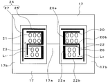
- FIG. 4 is a longitudinal sectional view showing another conventional transformer.
- FIG. 5 is a longitudinal sectional view of FIG. 4 viewed from the side.
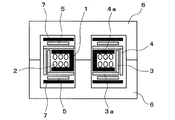
- FIG. 1 shows a first embodiment of a transformer according to the present invention.
- reference numeral 10 denotes a bobbin (first bobbin).
- This bobbin 10 is formed by integrally forming an annular plate-shaped flange portion 10b at both ends of a cylindrical winding portion 10a, and a stranded wire is wound around the outer periphery of the winding portion 10a.
- a high voltage coil (first coil) 11 is formed.
- the low voltage coil (2nd coil) 12 is arrange
- the low voltage coil 12 is obtained by punching a copper plate (metal flat plate) into a ring-opening ring shape, and is arranged coaxially with the high voltage coil 11.
- the bobbin 10 and the low voltage coil 12 around which the high voltage coil 11 is wound are housed in an insulating case 13.
- the case 13 includes a disk-shaped bottom plate (insulating member) 14 and a cylindrical side wall 15 that is integrally formed on the outer peripheral edge of the bottom plate 14 and surrounds the outer periphery of the high-voltage coil 11 and the low-voltage coil 12.
- the bottomed cylindrical shape is configured, and the opening is closed by a cap (insulating member) 16.
- a pair of E-type cores 17 forming a closed magnetic circuit are disposed on the outer periphery of the case 13 and the cap 16 so as to face each other. These E-shaped cores 17 are inserted into the through holes of the bobbin 10 through the openings formed in the center portions of the case 13 and the cap 16, and the outer feet 17 b are attached to the side wall 15 of the case 13. Are arranged along.
- cylindrical protrusions 18 that extend in the axial direction of the bobbin 10 and surround the outer periphery of the low-voltage coil 12 are integrally formed on the outer peripheral edge portions of both flange portions 10b of the bobbin 10. ing. Further, on the opposing surfaces of the bottom plate 14 of the case 13 and the low voltage coil 12 of the cap 16, a cylindrical first protruding to the flange 10 b side of the bobbin 10 between the protrusion 18 and the outer periphery of the low voltage coil 12, respectively. Two projecting portions 19 are integrally formed.
- the projecting portion 18 has a length dimension in the axial direction.
- the tip of the projecting portion 18 is the bottom plate of the case 13. 14 or the cap 16 is formed in a length dimension.
- the second projecting portion 19 accommodates the low voltage coil 12 and is formed at a position that restricts the movement of the low voltage coil 12 in the direction orthogonal to the axis, and the length dimension in the axial direction is In a state where the bobbin 10 and the low voltage coil 12 are housed in the case 13 and the cap 16 is attached, the tip end portion is formed to have a length dimension that abuts against the flange portion 10b of the bobbin 10.
- a cylindrical protrusion 18 that surrounds the outer periphery of the low voltage coil 12 is formed on the outer peripheral edge of the flange 10b of the bobbin 10 around which the high voltage coil 11 is wound.
- the creepage distance L 1 between the high pressure coil 11 and the low pressure coil 12 overlap with the axial length of the protrusion 18 from the outer periphery, further protrusion and the second protrusion of the pressure coil 11 This is the length dimension in the axial direction of the part.
- the creeping distance L 1 between the high voltage coil 11 and the low voltage coil and the creeping distance L 2 between the high voltage coil 11 and the core 17 are increased by the protrusion 18 and the second protrusion 19. Therefore, the required creeping distance can be ensured by appropriately setting the lengths in the axial direction of the protrusions 18 and the second protrusions 19.
- the predetermined insulation distances L 1 and L 2 can be easily ensured without increasing the size of the entire transformer.
- the number of components can be reduced to reduce the cost.
- FIG. 2 shows a second embodiment of a transformer according to the present invention. Since the configuration of the E-type core 17 is the same as that shown in FIG. 1, the same reference numerals are given and the description is simplified.
- a high voltage coil (first coil) 21 in which a stranded wire is wound around a winding portion 20 a of a bobbin (first bobbin) 20 and a winding portion 22 a of a bobbin (second bobbin) 22.
- a low-voltage coil (second coil) 23 in which a copper wire or a stranded wire is wound around ⁇ is disposed adjacent to the axial direction.
- the bobbins 20 and 22 stacked in the axial direction are housed in a bottomed cylindrical case 24.
- the bobbin 20 around which the high voltage coil 21 is wound is disposed on the top plate (insulating member) 25 side of the case 24, and the bobbin 22 around which the low voltage coil 23 is wound is connected to the opening side of the case 24. Is arranged.
- the flange portion 22 b on the opening side of the bobbin 22 is an insulating member between the low voltage coil 23 and the E-type core 17.
- a cylindrical protrusion that extends in the axial direction and surrounds the outer periphery of the low voltage coil 23 is formed on the outer peripheral edge of the flange 20b of the bobbin 20 adjacent to the bobbin 22 around which the low voltage coil 23 is wound.
- the part 26 is integrally formed.
- the protruding portion 26 has a length dimension in the axial direction such that the tip end portion of the protruding portion 26 abuts against the flange portion 22b on the opening side of the bobbin 22 in a state where the bobbins 20 and 22 are stacked. It is formed in the size.
- the flange portion 22b on the opening side has an outer diameter that is larger than that of the protruding portion 26 of the bobbin 20, and more specifically, an outer peripheral edge thereof is close to the side wall 27 of the case 24. ing.
- the protruding portion 26 that covers the outer periphery of the low voltage coil 23 is formed on the flange portion 20b of the bobbin 20 around which the high voltage coil 21 is wound.
- the creepage distance L 1 between the first and second electrodes is obtained by adding the length of the protruding portion 26 in the axial direction from the outer periphery of the high-voltage coil 21.
- the creepage distance L 2 between the low voltage coil 23 and the core 17 is a length dimension from the outer peripheral edge of the flange portion 22 b of the bobbin 22 to the outer periphery of the low voltage coil 23.
- the first embodiment is used.
- the same effects as those shown can be obtained.
Landscapes
- Engineering & Computer Science (AREA)
- Power Engineering (AREA)
- Coils Of Transformers For General Uses (AREA)
- Insulating Of Coils (AREA)
Priority Applications (2)
| Application Number | Priority Date | Filing Date | Title |
|---|---|---|---|
| EP14794993.7A EP2996122A4 (de) | 2013-05-09 | 2014-04-07 | Wandler |
| US14/787,376 US20160111206A1 (en) | 2013-05-09 | 2014-04-07 | Transformer |
Applications Claiming Priority (2)
| Application Number | Priority Date | Filing Date | Title |
|---|---|---|---|
| JP2013099504A JP6187806B2 (ja) | 2013-05-09 | 2013-05-09 | トランス |
| JP2013-099504 | 2013-05-09 |
Publications (1)
| Publication Number | Publication Date |
|---|---|
| WO2014181497A1 true WO2014181497A1 (ja) | 2014-11-13 |
Family
ID=51866989
Family Applications (1)
| Application Number | Title | Priority Date | Filing Date |
|---|---|---|---|
| PCT/JP2014/001987 Ceased WO2014181497A1 (ja) | 2013-05-09 | 2014-04-07 | トランス |
Country Status (4)
| Country | Link |
|---|---|
| US (1) | US20160111206A1 (de) |
| EP (1) | EP2996122A4 (de) |
| JP (1) | JP6187806B2 (de) |
| WO (1) | WO2014181497A1 (de) |
Families Citing this family (3)
| Publication number | Priority date | Publication date | Assignee | Title |
|---|---|---|---|---|
| WO2018088404A1 (ja) * | 2016-11-09 | 2018-05-17 | Ntn株式会社 | インダクタ |
| KR102702931B1 (ko) * | 2019-02-07 | 2024-09-05 | 엘지이노텍 주식회사 | 트랜스포머 및 이를 포함하는 직류 컨버터 |
| US12580120B2 (en) * | 2020-07-17 | 2026-03-17 | Lg Innotek Co., Ltd. | Transformer and flat panel display device comprising same |
Citations (2)
| Publication number | Priority date | Publication date | Assignee | Title |
|---|---|---|---|---|
| JP2000223320A (ja) | 1999-01-28 | 2000-08-11 | Hitachi Ferrite Electronics Ltd | 大電流用トランス |
| JP2003188030A (ja) * | 2001-12-18 | 2003-07-04 | Denso Corp | 成形コイルを用いる車両用降圧トランス |
Family Cites Families (9)
| Publication number | Priority date | Publication date | Assignee | Title |
|---|---|---|---|---|
| DE7105903U (de) * | 1971-02-17 | 1971-06-03 | Schutzapparate Ges Paris + Co Mbh Kg | Trenntransformator fuer rasiersteckdosen und dg. |
| JPS4862517U (de) * | 1971-11-18 | 1973-08-09 | ||
| JPH02222510A (ja) * | 1989-02-23 | 1990-09-05 | Matsushita Electric Ind Co Ltd | 漏洩型高周波高圧トランス |
| US5359313A (en) * | 1991-12-10 | 1994-10-25 | Toko, Inc. | Step-up transformer |
| JP3755729B2 (ja) * | 2000-03-21 | 2006-03-15 | Tdk株式会社 | 電源トランス |
| US6906609B1 (en) * | 2000-04-07 | 2005-06-14 | Astec International Limited | Planar transformer |
| US6522233B1 (en) * | 2001-10-09 | 2003-02-18 | Tdk Corporation | Coil apparatus |
| TWI381404B (zh) * | 2010-03-12 | 2013-01-01 | Delta Electronics Inc | 組合式變壓器結構 |
| TWM405042U (en) * | 2010-08-03 | 2011-06-01 | Yujing Technology Co Ltd | Laminated brush type step-down side transformer |
-
2013
- 2013-05-09 JP JP2013099504A patent/JP6187806B2/ja active Active
-
2014
- 2014-04-07 US US14/787,376 patent/US20160111206A1/en not_active Abandoned
- 2014-04-07 WO PCT/JP2014/001987 patent/WO2014181497A1/ja not_active Ceased
- 2014-04-07 EP EP14794993.7A patent/EP2996122A4/de not_active Withdrawn
Patent Citations (2)
| Publication number | Priority date | Publication date | Assignee | Title |
|---|---|---|---|---|
| JP2000223320A (ja) | 1999-01-28 | 2000-08-11 | Hitachi Ferrite Electronics Ltd | 大電流用トランス |
| JP2003188030A (ja) * | 2001-12-18 | 2003-07-04 | Denso Corp | 成形コイルを用いる車両用降圧トランス |
Non-Patent Citations (1)
| Title |
|---|
| See also references of EP2996122A4 * |
Also Published As
| Publication number | Publication date |
|---|---|
| US20160111206A1 (en) | 2016-04-21 |
| JP2014220421A (ja) | 2014-11-20 |
| JP6187806B2 (ja) | 2017-08-30 |
| EP2996122A4 (de) | 2017-01-04 |
| EP2996122A1 (de) | 2016-03-16 |
Similar Documents
| Publication | Publication Date | Title |
|---|---|---|
| JP6079225B2 (ja) | トランス | |
| JP6380745B2 (ja) | トランス | |
| US10398029B2 (en) | High-frequency transformer | |
| US10381154B2 (en) | High-voltage and high-frequency insulation transformer | |
| JP2015185725A (ja) | トランス | |
| US7221252B1 (en) | Transformer | |
| JP6187806B2 (ja) | トランス | |
| JP5189637B2 (ja) | コイル部品及びそれを用いた電源回路 | |
| JP2012164914A (ja) | トランス | |
| WO2014162684A1 (ja) | 電源トランス | |
| JP6495148B2 (ja) | トランス | |
| JP2010251364A (ja) | コイル用ボビン、巻線部品、コイル部品、スイッチング電源装置、及びコイル部品の製造方法 | |
| JP6210403B2 (ja) | 巻線部品 | |
| JP2008124433A (ja) | パルス電源用巻線機器及びパルス電源 | |
| JPWO2010098029A1 (ja) | 変圧器および変圧器の組み立て方法 | |
| JP2016100465A (ja) | チョークコイル | |
| US9449755B2 (en) | Arrangement having at least two coils which are arranged axially one above the other on a common core limb | |
| CN101123137A (zh) | 具有绝缘结构的变压器 | |
| JP2014049681A (ja) | トランス | |
| JP2016092232A (ja) | 巻線部品 | |
| JP2012182339A (ja) | トランス | |
| JP5903817B2 (ja) | リアクトル装置 | |
| WO2017221800A1 (ja) | インダクタ | |
| JP2011146534A (ja) | コンバータトランス | |
| JP2009038165A (ja) | トランス装置 |
Legal Events
| Date | Code | Title | Description |
|---|---|---|---|
| 121 | Ep: the epo has been informed by wipo that ep was designated in this application |
Ref document number: 14794993 Country of ref document: EP Kind code of ref document: A1 |
|
| WWE | Wipo information: entry into national phase |
Ref document number: 14787376 Country of ref document: US |
|
| NENP | Non-entry into the national phase |
Ref country code: DE |
|
| REEP | Request for entry into the european phase |
Ref document number: 2014794993 Country of ref document: EP |
|
| WWE | Wipo information: entry into national phase |
Ref document number: 2014794993 Country of ref document: EP |