WO2014184832A1 - 接合構造体及びその接合方法 - Google Patents
接合構造体及びその接合方法 Download PDFInfo
- Publication number
- WO2014184832A1 WO2014184832A1 PCT/JP2013/007481 JP2013007481W WO2014184832A1 WO 2014184832 A1 WO2014184832 A1 WO 2014184832A1 JP 2013007481 W JP2013007481 W JP 2013007481W WO 2014184832 A1 WO2014184832 A1 WO 2014184832A1
- Authority
- WO
- WIPO (PCT)
- Prior art keywords
- caulking portion
- cylindrical member
- shaft member
- peripheral surface
- axial
- Prior art date
- Legal status (The legal status is an assumption and is not a legal conclusion. Google has not performed a legal analysis and makes no representation as to the accuracy of the status listed.)
- Ceased
Links
Images



Classifications
-
- F—MECHANICAL ENGINEERING; LIGHTING; HEATING; WEAPONS; BLASTING
- F16—ENGINEERING ELEMENTS AND UNITS; GENERAL MEASURES FOR PRODUCING AND MAINTAINING EFFECTIVE FUNCTIONING OF MACHINES OR INSTALLATIONS; THERMAL INSULATION IN GENERAL
- F16B—DEVICES FOR FASTENING OR SECURING CONSTRUCTIONAL ELEMENTS OR MACHINE PARTS TOGETHER, e.g. NAILS, BOLTS, CIRCLIPS, CLAMPS, CLIPS OR WEDGES; JOINTS OR JOINTING
- F16B7/00—Connections of rods or tubes, e.g. of non-circular section, mutually, including resilient connections
-
- F—MECHANICAL ENGINEERING; LIGHTING; HEATING; WEAPONS; BLASTING
- F16—ENGINEERING ELEMENTS AND UNITS; GENERAL MEASURES FOR PRODUCING AND MAINTAINING EFFECTIVE FUNCTIONING OF MACHINES OR INSTALLATIONS; THERMAL INSULATION IN GENERAL
- F16D—COUPLINGS FOR TRANSMITTING ROTATION; CLUTCHES; BRAKES
- F16D1/00—Couplings for rigidly connecting two coaxial shafts or other movable machine elements
- F16D1/06—Couplings for rigidly connecting two coaxial shafts or other movable machine elements for attachment of a member on a shaft or on a shaft-end
- F16D1/064—Couplings for rigidly connecting two coaxial shafts or other movable machine elements for attachment of a member on a shaft or on a shaft-end non-disconnectable
- F16D1/072—Couplings for rigidly connecting two coaxial shafts or other movable machine elements for attachment of a member on a shaft or on a shaft-end non-disconnectable involving plastic deformation
-
- B—PERFORMING OPERATIONS; TRANSPORTING
- B21—MECHANICAL METAL-WORKING WITHOUT ESSENTIALLY REMOVING MATERIAL; PUNCHING METAL
- B21D—WORKING OR PROCESSING OF SHEET METAL OR METAL TUBES, RODS OR PROFILES WITHOUT ESSENTIALLY REMOVING MATERIAL; PUNCHING METAL
- B21D39/00—Application of procedures in order to connect objects or parts, e.g. coating with sheet metal otherwise than by plating; Tube expanders
- B21D39/04—Application of procedures in order to connect objects or parts, e.g. coating with sheet metal otherwise than by plating; Tube expanders of tubes with tubes; of tubes with rods
- B21D39/048—Application of procedures in order to connect objects or parts, e.g. coating with sheet metal otherwise than by plating; Tube expanders of tubes with tubes; of tubes with rods using presses for radially crimping tubular elements
-
- F—MECHANICAL ENGINEERING; LIGHTING; HEATING; WEAPONS; BLASTING
- F16—ENGINEERING ELEMENTS AND UNITS; GENERAL MEASURES FOR PRODUCING AND MAINTAINING EFFECTIVE FUNCTIONING OF MACHINES OR INSTALLATIONS; THERMAL INSULATION IN GENERAL
- F16B—DEVICES FOR FASTENING OR SECURING CONSTRUCTIONAL ELEMENTS OR MACHINE PARTS TOGETHER, e.g. NAILS, BOLTS, CIRCLIPS, CLAMPS, CLIPS OR WEDGES; JOINTS OR JOINTING
- F16B17/00—Connecting constructional elements or machine parts by a part of or on one member entering a hole in the other and involving plastic deformation
- F16B17/004—Connecting constructional elements or machine parts by a part of or on one member entering a hole in the other and involving plastic deformation of rods or tubes mutually
-
- F—MECHANICAL ENGINEERING; LIGHTING; HEATING; WEAPONS; BLASTING
- F16—ENGINEERING ELEMENTS AND UNITS; GENERAL MEASURES FOR PRODUCING AND MAINTAINING EFFECTIVE FUNCTIONING OF MACHINES OR INSTALLATIONS; THERMAL INSULATION IN GENERAL
- F16B—DEVICES FOR FASTENING OR SECURING CONSTRUCTIONAL ELEMENTS OR MACHINE PARTS TOGETHER, e.g. NAILS, BOLTS, CIRCLIPS, CLAMPS, CLIPS OR WEDGES; JOINTS OR JOINTING
- F16B7/00—Connections of rods or tubes, e.g. of non-circular section, mutually, including resilient connections
- F16B7/04—Clamping or clipping connections
- F16B7/0406—Clamping or clipping connections for rods or tubes being coaxial
- F16B7/0413—Clamping or clipping connections for rods or tubes being coaxial for tubes using the innerside thereof
-
- F—MECHANICAL ENGINEERING; LIGHTING; HEATING; WEAPONS; BLASTING
- F16—ENGINEERING ELEMENTS AND UNITS; GENERAL MEASURES FOR PRODUCING AND MAINTAINING EFFECTIVE FUNCTIONING OF MACHINES OR INSTALLATIONS; THERMAL INSULATION IN GENERAL
- F16D—COUPLINGS FOR TRANSMITTING ROTATION; CLUTCHES; BRAKES
- F16D2300/00—Special features for couplings or clutches
- F16D2300/18—Sensors; Details or arrangements thereof
-
- Y—GENERAL TAGGING OF NEW TECHNOLOGICAL DEVELOPMENTS; GENERAL TAGGING OF CROSS-SECTIONAL TECHNOLOGIES SPANNING OVER SEVERAL SECTIONS OF THE IPC; TECHNICAL SUBJECTS COVERED BY FORMER USPC CROSS-REFERENCE ART COLLECTIONS [XRACs] AND DIGESTS
- Y10—TECHNICAL SUBJECTS COVERED BY FORMER USPC
- Y10T—TECHNICAL SUBJECTS COVERED BY FORMER US CLASSIFICATION
- Y10T403/00—Joints and connections
- Y10T403/49—Member deformed in situ
Definitions
- the present invention relates to a joined structure and a joining method thereof, and more particularly, to a joined structure by caulking joining of a shaft member and a cylindrical member used in a torque sensor and a joining method thereof.
- Patent Document 1 discloses.
- a torque sensor is mentioned.
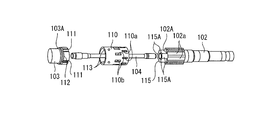
- the torque sensor disclosed in Patent Document 1 has a plurality of axial grooves 111 extending in the axial direction and a circumferential groove 122 continuous in the circumferential direction on the outer peripheral surface of the large-diameter portion 103 ⁇ / b> A at the end of the output shaft 103.
- the axial groove 111 is formed between both end portions of the large-diameter portion 103A, and the circumferential groove 122 is formed near the end of the cylindrical member 110 when the cylindrical member 110 is fixed. .
- a plurality of hemispherical protrusions 113 are formed at positions slightly protruding from the lower end portion of the inner peripheral surface of the cylindrical member 110.
- the number and formation position of the protrusions 113 correspond to the axial grooves 111, and the height of the protrusions 113 is approximately the same as the depth of the axial grooves 111.
- the torque sensor described in Patent Document 1 has room for improvement with respect to the following points (1) to (4).
- (1) When a projection provided in advance on a cylindrical member is fitted in the groove, there is a possibility that a problem such as a gap in the fitting portion or a shaving of the projection may occur depending on each processing accuracy. For example, in a combination in which the inscribed diameter of the protrusion is larger than the groove bottom diameter, there is a possibility that play occurs in the rotational direction.
- the protrusions are formed by plastic working, the ridges of the protrusions may be bent by the spring back, and may interfere with the groove shoulder. When the cylindrical member is inserted into the shaft member in such a state, the projection of the cylindrical member is scraped to cause contamination, which may cause a problem.
- An embodiment of a joint structure for achieving the above object includes a shaft member, and a cylindrical member having an inner peripheral surface fitted to the outer peripheral surface of the shaft member, The cylindrical member is engaged with a plurality of first caulking portions that are caulked along a plurality of axial grooves provided in the axial direction of the shaft member, and an axial intermediate portion is engaged with the axial groove. And a second caulking portion that is caulked along a circumferential groove provided on the circumferential surface of the shaft member.
- the joining structure may have a shape in which the first caulking portion protrudes as a spherical protrusion on the inner peripheral surface of the cylindrical member.
- the joining structure may be laid out so that the positions of the apexes in the axial direction of the protrusions are within a predetermined range on the side surface side of the circumferential groove.
- an inscribed diameter of the first caulking portion may be set to be larger than a curvature radius of a bottom portion in a cross section along the circumferential direction of the axial groove.
- the joint structure may have a bathtub shape in a cross-sectional shape along the axial direction of the circumferential groove.
- a temporary first caulking in which a plurality of protrusions are formed on the inner peripheral surface of the cylindrical member so as to engage with a plurality of axial grooves provided in the shaft member.
- Part forming step The outer peripheral surface of the shaft member and the inner peripheral surface of the cylindrical member are in contact with each other, and a plurality of axial grooves provided in the shaft member, a circumferential groove provided in the peripheral surface of the shaft member, and the cylinder The shaft member and the cylindrical member are fitted so that the protrusion on the inner peripheral surface of the member is engaged, The position of the apex in the axial direction of the projection of the temporary first caulking portion is laid out within a predetermined range on the side surface side of the circumferential groove, and along the circumferential groove provided on the circumferential surface of the shaft member, A caulking portion forming step of simultaneously forming a first caulking portion and a second caulking portion that is connected to the first caulking portion
- the first projection is formed with a plurality of protrusions on the inner peripheral surface of the cylindrical member so as to engage with the plurality of axial grooves provided on the shaft member.
- a second caulking portion that is connected to the first caulking portion and caulked along a circumferential groove provided on the peripheral surface of the shaft member is formed by radially reducing the axial intermediate portion of the cylindrical member.
- the joining method of the joining structure may be such that the first caulking portion protrudes as a spherical projection on the inner peripheral surface of the cylindrical member.
- the inscribed diameter of the first caulking portion may be set larger than the curvature radius of the bottom portion in the cross section along the circumferential direction of the axial groove.
- channel may be bathtub shape.
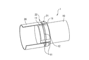
- FIG. 1 is a perspective view showing a configuration in an embodiment of a joint structure according to the present invention.
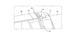
- FIG. 2 is a partial cross-sectional view showing a configuration in an embodiment of the joint structure according to the present invention.
- FIG. 3 is a partial cross-sectional view of the main part showing the configuration in an embodiment of the joint structure according to the present invention.
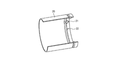
- FIG. 4 is a partial cross-sectional view showing a configuration of a cylindrical member in an embodiment having a joint structure according to the present invention. Note that FIG. 4 is a view expressed by removing the shaft member in FIGS. 1 and 2.
- the joint structure 1 of the present embodiment includes a shaft member 10 and a cylindrical member 20 in which an inner peripheral surface is fitted to the outer peripheral surface of the shaft member 10.
- the shaft member 10 is provided with a plurality of axial grooves 11 along the axial direction on the circumferential surface thereof. Further, the shaft member 10 is provided with a circumferential groove 12 over the entire circumference thereof.
- the cylindrical member 20 is engaged with the plurality of first caulking portions 21 caulked along the plurality of axial grooves 11 and the axial groove 11, and the axial intermediate portion is radially reduced in diameter to form a shaft member. 10 and a second caulking portion 22 caulked along the circumferential groove 12. In the present embodiment, the second caulking portion 22 is provided over the entire circumference of the cylindrical member 20.
- the first caulking portion 21 is provided at the intersection of the axial groove 11 and the circumferential groove 12, and the second caulking portion 22 having a reduced diameter of the cylindrical member 20 is formed on the first caulking portion 21. Is formed. Specifically, as shown in FIG. 4, a protrusion protruding inward from the inner peripheral surface of the cylindrical member 20 (hereinafter simply referred to as a protrusion) is deformed by caulking, and the side surface shape of the axial groove 11 is changed. It has been transcribed. Further, as shown in FIG. 4, the first caulking portion 21 preferably has a shape protruding as a spherical protrusion on the inner peripheral surface of the cylindrical member 20. The inscribed diameter of the first caulking portion 21 is preferably set to be larger than the curvature radius of the bottom portion in the cross section along the circumferential direction of the axial groove 11.
- FIG. 5 is a partial cross-sectional view illustrating a state before the first caulking portion forming step in an embodiment of the bonding structure bonding method.
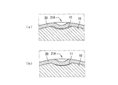
- FIG. 6 is a partial cross-sectional view of the main part in the first caulking part forming step in an embodiment of the joining method of the joined structure, wherein (a) is before the first caulking part forming process, and (b) is the first. After the first caulking portion forming step.
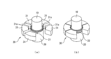
- FIG. 7 is a perspective view showing a state of the second caulking portion forming step in an embodiment of the joining method of the joined structure, wherein (a) is before the second caulking portion forming step, and (b) is the second. After the caulking portion forming step.
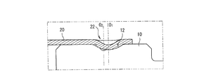
- FIG. 8 is a partial cross-sectional view of the main part showing a state after the second caulking part forming step in an embodiment of the joining method of the joined structure.
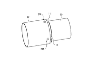
- the joining structure of the present embodiment includes a temporary first caulking portion forming step for forming the temporary first caulking portion 21A (see FIG.
- the temporary first caulking portion forming step is a step of forming a plurality of protrusions on the inner peripheral surface of the cylindrical member 20 so as to engage with the plurality of axial grooves 11 provided in the shaft member 10.
- the temporary first caulking portion 21 ⁇ / b> A is a protrusion that is provided in advance at a position where the first caulking portion 21 is provided on the outer peripheral surface of the cylindrical member 20 and protrudes to the inner peripheral surface of the circumferential member 20. That is, the cylindrical member 20 is fitted to the shaft member 10 while engaging the projection of the temporary first caulking portion 21A with the axial groove 11 (see FIG. 5).
- a temporary first caulking portion 21A provided in the cylindrical member 20 by the temporary first caulking portion forming step will be described later.
- the relationship between the inscribed diameter of the protrusion protruding from the inner peripheral surface of the cylindrical member of the temporary first caulking portion and the curvature radius of the bottom portion in the cross section along the circumferential direction of the axial groove will be described.
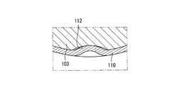
- FIG. 14 is a cross-sectional view of the main part showing a fitting state when a cylindrical member is caulked against an axial member having an axial groove whose cross-sectional shape along the circumferential direction is a single arc.
- the contact between the protrusion and the axial groove is only at the apex (groove bottom) of the protrusion and does not have rigidity in the rotation direction, so that the function as a rotation stopper is not sufficient.
- This is not limited to the case where the cross-sectional shape of the axial groove is a single arc, but is applicable to all cases where fitting is performed at the apex of the protrusion.
- FIG. 15 shows that the inscribed diameter of the protruding portion protruding from the inner peripheral surface of the cylindrical member of the temporary first caulking portion and the radius of curvature of the bottom portion in the cross section along the circumferential direction of the axial groove are caulked.
- It is principal part sectional drawing which shows the fitting state at the time of a case.
- rigidity in the rotational direction can be obtained, but there is a high possibility that the shoulder portion of the axial groove damages the projection due to a phase shift during assembly.
- the protrusions are provided on the cylindrical member 20 by plastic working, there is a possibility that sagging of the protrusions may occur due to the spring back. In order to avoid this, it is necessary to provide relief in the shoulder portion of the axial groove, and the fitting depth between the axial groove and the projection becomes shallow.
- the inscribed diameter of the protrusion protruding from the inner peripheral surface of the cylindrical member 20 of the temporary first caulking portion 21A provided in advance in the cylindrical member 20 is the circumferential direction of the axial groove 11 of the shaft member 10. Is set to be larger than the curvature radius of the bottom in the cross section along the line. That is, in the state shown in FIG. 6A (before the first caulking portion forming step), the projection protruding from the inner peripheral surface of the cylindrical member 20 of the temporary first caulking portion 21A provided in advance in the cylindrical member 20 and the axial direction There is a gap between the groove. Therefore, in the assembly process, the axial groove 11 does not scrape off the protrusion of the temporary first caulking portion 21A. Moreover, since the protrusion and the shaft member 10 do not contact, the assembly accuracy is not affected by the processing accuracy of the protrusion.
- the protrusion protruding from the inner peripheral surface of the cylindrical member 20 is formed in the axial groove 11 as shown in FIG.
- the projection is deformed and the axial groove 11 comes into contact with the projection.
- the inscribed diameter of the protrusion protruding from the inner peripheral surface of the cylindrical member 20 of the first caulking portion 21 is the curvature of the bottom portion in the cross section along the circumferential direction of the axial groove 11. It is still greater than the radius. With such a configuration, it is possible to stably guarantee the rotation stopping function regardless of the dimensional relationship between the protrusion and the axial groove 11.
- ⁇ Second caulking part forming step> In the second caulking portion forming step, as shown in FIGS. 7A and 7B, the axial intermediate portion of the cylindrical member 20 fitted to the shaft member 10 is used in the radial direction using the mold 30. This is a step of reducing the diameter and forming the second caulking portion 22 by caulking along the circumferential groove 12 of the shaft member 10. In the second caulking portion forming step, the second caulking portion 22 is formed to be connected to the first caulking portion.
- the mold 30 is a member that forms an annular shape by combining a plurality of divided bodies 31 having a substantially fan shape whose inner peripheral surface is in contact with the outer diameter of the cylindrical member 20 in the circumferential direction.
- the divided body 31 has a shape obtained by dividing an annular mold 30 into six parts.
- the display of one divided body 31 is omitted.
- Each divided body 31 has a convex portion 31 a on the inner peripheral surface for pushing the cylindrical member 20 into the circumferential groove 12 to form the second caulking portion 22.
- the mold 30 is formed so as to surround the cylindrical member 20 on the outer peripheral surface side with respect to the cylindrical member 20 after the first caulking portion forming step. set.
- each divided body 31 a is pushed in while being synchronized with an apparatus (not shown) that synchronizes each divided body 31 a so as to be pushed toward the axis of the mold 30.
- the cylindrical member 20 is reduced in diameter in the radial direction, and is connected to the first caulking portion 21 to form the second caulking portion 22 that is caulked along the circumferential groove 12.
- the position O 1 of the apex in the axial direction of the protrusion protruding from the inner peripheral surface of the cylindrical member 20 of the second caulking portion 22 is set to the circumferential groove.
- the position O 1 of the apex in the axial direction of the protrusion is laid out within a predetermined range on the side surface side of the circumferential groove 12.
- the protrusions are laid out not only as “protrusions of the second caulking portion 22” but also as protrusions of the temporary first caulking portion 21 ⁇ / b> A, and the cylindrical member 20 is arranged in the radial direction along the circumferential groove 12.
- the step of simultaneously performing the first caulking portion forming step and the second caulking portion forming step is referred to as a caulking portion forming step.
- FIG. 9 is a cross-sectional view showing the structure of the circumferential groove in another embodiment of the bonded structure and the bonding method thereof.
- FIG. 10 is a perspective view showing a state of the second caulking portion forming step in another embodiment of the joined structure and the joining method thereof, (a) before the second caulking portion forming step, and (b). After the second caulking portion forming step.
- the description of the same configuration as the above-described embodiment is omitted.
- the cross-sectional shape along the circumferential direction of the axial groove 11 of the shaft member 10 is a bathtub type.
- the said protrusion can contact the both sides
- a flat portion is provided at the bottom of the axial groove 11, and both sides thereof are rounded up by 60 °.
- the opening width of the axial groove 11 is designed to be wider than the width of the flange of the protrusion, and at the time of assembly, it is set to a dimensional relationship in which the shoulder portion of the axial groove 11 and the protrusion do not interfere with each other.
- channel 11 is processed by the cold forging process, and the shaft member 10 is shape
- burrs may be generated when the outer peripheral surface is cut, and may come into contact with the protrusions.
- both side surfaces of the axial groove 11 have a shape that opens outward in the vicinity of the outer peripheral surface of the shaft member 10.
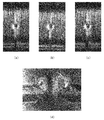
- FIGS. 11 (a) to 11 (c) are photographs in which the protrusions are seen from directly above the outer diameter side of the cylindrical member 20, and the reduced diameter caulking proceeds as FIGS. 11 (a), 11 (b), and 11 (c). It is the photograph which showed the aspect.
- FIG. 11D is a photograph showing a state of the protrusion on the inner diameter side of the cylindrical member 20 after completion of the crimping. In this photograph, it can be confirmed that the side surface shape of the axial groove 11 is transferred to both side surfaces of the protrusion. As shown in FIGS. 11 (a) to 11 (d), it can be seen that the protrusion and the side surface of the axial groove 11 are brought into contact with each other so that they can be joined without play in the rotational direction.
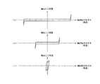
- FIG. 12 is a graph showing the anti-rotation effect of the protrusions.
- the torque applied to the joint between the shaft member 10 and the cylindrical member 20 is shown on the vertical axis, and the relative angle between the shaft member 10 and the cylindrical member 20 is shown. Is shown on the horizontal axis. Note that the torque rise at both ends of each diagram shows the point at which the torque comes into contact with the side surface of the axial groove 11.
- FIGS. 12 (a) to 12 (c) show the measurement results of the states in FIGS. 11 (a) to 11 (c), and show the relationship between the progress of shrinkage caulking and the play in the rotational direction. is there. As shown in FIGS.
- the diameter reduction caulking proceeds and the protrusions come into contact with the side surface of the axial groove 11 to reduce the backlash in the rotational direction.
- the first caulking portion formed in the cylindrical member 20 is pushed into the axial groove 11 as the cylindrical member 20 is caulked in the second caulking portion forming step. As a result, it is deformed so that it can function as a rotation stopper.
- the protrusion and the axial groove 11 are in a complete gap relationship at the time of assembly, there is a concern about the above-described removal of the protrusion and the influence on the assembly accuracy. There is no need to do.
- the protrusion deforms toward the axial groove 11 as the cylindrical member 20 is reduced in diameter and caulked. Therefore, after caulking (after the second caulking portion forming step), the gap between the projection and the axial groove 11 disappears, and the function as a rotation stopper is exhibited. Therefore, it is possible to provide a joint structure that can suitably join the shaft member and the cylindrical member constituting the joint structure, and a joining method thereof.
- the bonded structure and the bonding method thereof have been described.
- the bonded structure and the bonding method according to the present invention are not limited to the above embodiment, and various modifications can be made without departing from the gist of the present invention. Is possible.
- the detailed conditions such as the shape and number of the axial grooves and the circumferential grooves and the shapes and numbers of the first and second caulking portions can be changed within a range in which the function of the present invention is exhibited.
Landscapes
- Engineering & Computer Science (AREA)
- General Engineering & Computer Science (AREA)
- Mechanical Engineering (AREA)
- Mutual Connection Of Rods And Tubes (AREA)
- Control Of Indicators Other Than Cathode Ray Tubes (AREA)
- Control Of El Displays (AREA)
- Transforming Electric Information Into Light Information (AREA)
- Insertion Pins And Rivets (AREA)
- Shafts, Cranks, Connecting Bars, And Related Bearings (AREA)
- Standing Axle, Rod, Or Tube Structures Coupled By Welding, Adhesion, Or Deposition (AREA)
Abstract
Description
特許文献1のトルクセンサは、図13に示すように、出力軸103端部の大径部103A外周面に、軸方向に延びる複数の軸方向溝111と、周方向に連続した周方向溝122とを形成している。
軸方向溝111は、大径部103Aの両端部間に渡って形成し、周方向溝122は、円筒部材110を固定した際にその円筒部材110の端部が位置する付近に形成している。
円筒部材110を大径部103Aに固定する際には、突起113を軸方向溝111に嵌合させて円筒部材110の出力軸103に対する周方向の位置決めを行い、次いで、円筒部材110を押し込み、その端部を周方向溝122に近接させ、その状態で円筒部材110端部を内側にかしめて周方向溝122に食い込ませている。
このように、特許文献1に記載の技術では、軸部材に設けられた溝に円筒部材に設けた突起を嵌合することで、回転方向の位置ズレを防止している。
(1)予め円筒部材に設けた突起を溝に嵌合させる場合、各々の加工精度によって嵌合部の隙間や突起の削れといった不具合が発生する可能性がある。例えば、突起の内接径が溝底径よりも大きい組合せでは、回転方向にガタが生じてしまう可能性がある。
(2)突起を塑性加工で設けた場合、突起の麓にはスプリングバックによってダレが生じるため、溝肩と干渉する可能性がある。このような状態で、円筒部材を軸部材に挿入すると、円筒部材の突起が削られてコンタミが発生し、不具合の要因となり得る。
(4)突起内径と溝底とを嵌合させるため、円筒部材の組立精度が、突起内接径の影響を受けることがある。例えば、塑性加工で設けた突起の内接径と円筒部材の同軸度が十分でない場合、軸部材に対して円筒部材が偏芯してしまう可能性がある。
そこで、本発明は上記の問題点に着目してなされたものであり、その目的は、接合構造体を構成する部材間を好適に接合できる接合構造体及びその接合方法を提供することにある。
上記円筒部材は、上記軸部材の軸方向に設けられた複数の軸方向溝に沿ってかしめられた複数の第1かしめ部と、上記軸方向溝に係合し、軸方向の中間部を径方向に縮径されて上記軸部材の周面に設けられた周方向溝に沿ってかしめられた第2かしめ部とを有する。
ここで、上記接合構造体は、第1かしめ部が、上記円筒部材の内周面に球形の突起として突出した形状をなしてもよい。
また、上記接合構造体は、第1かしめ部の内接径が、上記軸方向溝の周方向に沿った断面における底部の曲率半径よりも大きく設定されてもよい。
また、上記接合構造体は、上記周方向溝の軸方向に沿った断面形状がバスタブ形状であってもよい。
上記軸部材の外周面と上記円筒部材の内周面とが当接し、かつ、上記軸部材に設けられた複数の軸方向溝及び上記軸部材の周面に設けられた周方向溝と上記円筒部材の内周面の突起とが係合するように、上記軸部材と上記円筒部材とを嵌合させ、
上記仮第1かしめ部の突起の軸方向の頂点の位置を、上記周方向溝の側面側の所定の範囲内にレイアウトし、上記軸部材の周面に設けられた周方向溝に沿って上記円筒部材を径方向に縮径することによって、第1かしめ部と、該第1かしめ部と連結され、上記周方向溝に沿ってかしめられた第2かしめ部とを同時に形成するかしめ部形成工程とを含む。
上記軸部材の外周面と上記円筒部材の内周面とが当接し、かつ、上記軸部材に設けられた複数の軸方向溝と上記円筒部材の内周面の突起とが係合するように、上記軸部材と上記円筒部材とを嵌合させ、
上記仮第1かしめ部を上記軸部材の軸方向溝に沿って変形させ、第1かしめ部を形成する第1かしめ部形成工程と、
上記円筒部材の軸方向の中間部を径方向に縮径して、第1かしめ部と連結され、上記軸部材の周面に設けられた周方向溝に沿ってかしめられた第2かしめ部を形成する第2かしめ部形成工程とを含む。
また、上記接合構造体の接合方法は、第1かしめ部の内接径が、上記軸方向溝の周方向に沿った断面における底部の曲率半径よりも大きく設定されてもよい。
また、上記接合構造体の接合方法は、上記周方向溝の軸方向に沿った断面形状がバスタブ形状であってもよい。
(接合構造体)
図1は、本発明に係る接合構造体のある実施形態における構成を示す斜視図である。また、図2は、本発明に係る接合構造体のある実施形態における構成を示す部分断面図である。また、図3は、本発明に係る接合構造体のある実施形態における構成を示す要部の部分断面図である。また、図4は、本発明に係る接合構造体のある実施形態における円筒部材の構成を示す部分断面図である。なお、図4は、図1及び図2において、軸部材を除いて表現した図である。
軸部材10には、その周面に軸方向に沿って複数の軸方向溝11が設けられている。また、軸部材10には、その周面全周にわたって周方向溝12が設けられている。
円筒部材20は、複数の軸方向溝11に沿ってかしめられた複数の第1かしめ部21と、軸方向溝11に係合し、軸方向の中間部を径方向に縮径されて軸部材10の周方向溝12に沿ってかしめられた第2かしめ部22とを有する。本実施形態では、第2かしめ部22は、円筒部材20の周面全周にわたって設けられている。
また、第1かしめ部21は、図4に示すように、円筒部材20の内周面に球形の突起として突出した形状をなすことが好ましい。
また、第1かしめ部21の内接径は、軸方向溝11の周方向に沿った断面における底部の曲率半径よりも大きく設定されることが好ましい。
次に、図1~4に示す接合構造体の接合方法について説明する。
図5は、接合構造体の接合方法のある実施形態における第1かしめ部形成工程前の状態を示す部分断面図である。また、図6は、接合構造体の接合方法のある実施形態における第1かしめ部形成工程における要部の部分断面図であり、(a)は第1かしめ部形成工程前、(b)は第1かしめ部形成工程後である。
本実施形態の接合構造体の接合方法は、仮第1かしめ部21A(図5参照)を円筒部材20に形成する仮第1かしめ部形成工程と、軸部材10の外周面と円筒部材20の内周面とが当接し、かつ軸方向溝11に仮第1かしめ部21Aを係合させながら軸部材10と円筒部材20とを嵌合させた後に、第1かしめ部形成工程と、第2かしめ部形成工程とを含む。
仮第1かしめ部形成工程は、円筒部材20の内周面に、軸部材10に設けられた複数の軸方向溝11と係合するように、複数の突起を形成する工程である。なお、仮第1かしめ部21Aは、円筒部材20の外周面上において第1かしめ部21が設けられる位置に予め設けられ、円周部材20の内周面に突出する突起である。すなわち、円筒部材20は、仮第1かしめ部21Aの突起を軸方向溝11に係合させながら軸部材10に嵌合させる(図5参照)。
また、第1かしめ部形成工程は、図6(a),(b)に示すように、上記仮第1かしめ部形成工程によって円筒部材20に設けられた仮第1かしめ部21Aを、後述する第2かしめ部形成工程によって形成される第2かしめ部の形成予定位置に合わせた状態で、仮第1かしめ部21Aをさらにかしめて第1かしめ部21を形成する工程である。
ここで、仮第1かしめ部の円筒部材の内周面から突出した突起の内接径と、軸方向溝の周方向に沿った断面における底部の曲率半径との関係について述べる。図14は、周方向に沿う断面形状が単一円弧である軸方向溝を有する軸部材に対して円筒部材をかしめた場合の嵌合状態を示す要部断面図である。
図14に示す態様では、上記突起と軸方向溝との接触は上記突起の頂点(溝底)のみで、回転方向に剛性を持たないため、回転止めとしての機能が十分ではない。これは、軸方向溝の断面形状が単一円弧である場合に限らず、上記突起の頂点で嵌合する全ての場合に当てはまる。
図15に示す態様では、回転方向の剛性は得られるが、組立時の位相ズレなどによって、軸方向溝の肩部が上記突起を損なう可能性が高くなる。
また、円筒部材20に上記突起を塑性加工で設けると、スプリングバックによって上記突起の麓にダレが生じる可能性がある。これを避けるためには、軸方向溝の肩部に逃げを設ける必要があり、軸方向溝と上記突起との嵌合深さが浅くなってしまう。
このような構成によって、上記突起と軸方向溝11との寸法関係に関係なく、安定して回転止め機能を保証することが可能になる。
第2かしめ部形成工程は、図7(a),(b)に示すように、金型30を用いて、軸部材10に嵌合させた円筒部材20の軸方向の中間部を径方向に縮径して、軸部材10の周方向溝12に沿ってかしめて第2かしめ部22を形成する工程である。なお、この第2かしめ部形成工程では、第2かしめ部22が第1かしめ部と連結されるように形成される。
金型30は、内周面が円筒部材20の外径に当接可能な形状とされた略扇形をなす複数の分割体31を周方向に組み合わせて円環形状をなす部材である。分割体31は、例えば、図7(a),(b)に示すように、円環形状の金型30を6分割した形状である。なお、図7(a),(b)は、1つの分割体31の表示を省略している。
各分割体31は、周方向溝12に円筒部材20を押込んで第2かしめ部22を形成するための凸部31aを内周面に有している。
第2かしめ部形成工程では、まず、図6(a)に示すように、第1かしめ部形成工程後の円筒部材20に対して、円筒部材20を外周面側で取り囲むように金型30をセットする。
ここで、第2かしめ部形成工程においては、図8に示すように、第2かしめ部22の円筒部材20の内周面から突出した突起の軸方向の頂点の位置O1を、周方向溝12の最下点の位置O2からずらした位置に設定することが好ましい。上記突起の軸方向の頂点の位置O1が周方向溝12の最下点の位置O2に位置すると、軸方向溝11と上記突起との係り代が小さくなり、所望の剛性を得難くなることがあるからである。一方、上記突起と周方向溝12とのオフセット量が大きすぎると、かしめによる上記突起の変形が不十分となり、上記突起が回転止めとしての機能を発揮しなくなる。
なお、図8においては、上記突起を「第2かしめ部22の突起」としてだけでなく、仮第1かしめ部21Aの突起としてもレイアウトし、周方向溝12に沿って円筒部材20を径方向に縮径することによって、第1かしめ部21と、該第1かしめ部21と連結され、周方向溝12に沿ってかしめられた第2かしめ部22とを同時に形成することができる。この第1かしめ部形成工程と第2かしめ部形成工程を同時に行う工程をかしめ部形成工程とする。
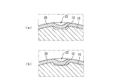
図9は、接合構造体及びその接合方法の他の実施形態における周方向溝の構造を示す断面図である。また、図10は、接合構造体及びその接合方法の他の実施形態における第2かしめ部形成工程の状態を示す斜視図であり、(a)は第2かしめ部形成工程前、(b)は第2かしめ部形成工程後である。なお、本実施形態の説明においては、前述した実施形態と重複する構成についての説明を省略する。
図9,図10に示すように、本実施形態では、軸部材10の軸方向溝11の周方向に沿う断面形状をバスタブ型としている。このような形状とすることで、上記突起が軸方向溝11の両側面に接触し、回転方向における剛性を得ることができる。なお、図9,10に示すように、本実施形態では、軸方向溝11の底部に平面部を設け、その両側を60°で切上げている。
また、軸方向溝11は、冷鍛加工によって加工されることが好ましく、軸部材10は冷鍛加工品に切削加工を施すことで成形される。このとき、軸方向溝11の側面が、軸部材10の外径に向かって直線的に切り上がっていると、外周面の切削時にバリが発生し、上記突起と接触する可能性がある。これを避けるため、軸方向溝11の両側面を、軸部材10の外周面の近傍で外側に開く形状とすることが好ましい。
以上説明したように、本発明のある実施形態によれば、円筒部材20に形成された第1かしめ部は、第2かしめ部形成工程における円筒部材20のかしめに伴い、軸方向溝11に押込まれるように変形され、結果として回転止めとしての機能を与えられることになる。
よって、接合構造体を構成する軸部材と円筒部材とを好適に接合できる接合構造体及びその接合方法を提供することができる。
能を発揮する範囲で変更可能である。
10 軸部材
11 軸方向溝
12 周方向溝
20 円筒部材
21 第1かしめ部(球状突起)
22 第2かしめ部
Claims (10)
- 軸部材と、該軸部材の外周面に内周面を嵌合させた円筒部材とを有し、
前記円筒部材は、前記軸部材の軸方向に設けられた複数の軸方向溝に沿ってかしめられた複数の第1かしめ部と、前記軸方向溝に係合し、軸方向の中間部を径方向に縮径されて前記軸部材の周面に設けられた周方向溝に沿ってかしめられた第2かしめ部とを有することを特徴とする接合構造体。 - 第1かしめ部は、前記円筒部材の内周面に球形の突起として突出した形状をなすことを特徴とする請求項1に記載の接合構造体。
- 前記突起の軸方向の頂点の位置を、前記周方向溝の側面側の所定の範囲内にレイアウトしたことを特徴とする請求項2に記載の接合構造体。
- 第1かしめ部の内接径は、前記軸方向溝の周方向に沿った断面における底部の曲率半径よりも大きく設定されたことを特徴とする請求項1~3の何れか一項に記載の接合構造体。
- 前記周方向溝の軸方向に沿った断面形状がバスタブ形状であることを特徴とする請求項1~4の何れか一項に記載の接合構造体。
- 円筒部材の内周面に、軸部材に設けられた複数の軸方向溝と係合するように、複数の突起を形成する仮第1かしめ部形成工程と、
前記軸部材の外周面と前記円筒部材の内周面とが当接し、かつ、前記軸部材に設けられた複数の軸方向溝及び前記軸部材の周面に設けられた周方向溝と前記円筒部材の内周面の突起とが係合するように、前記軸部材と前記円筒部材とを嵌合させ、
前記仮第1かしめ部の突起の軸方向の頂点の位置を、前記周方向溝の側面側の所定の範囲内にレイアウトし、前記軸部材の周面に設けられた周方向溝に沿って前記円筒部材を径方向に縮径することによって、第1かしめ部と、該第1かしめ部と連結され、前記周方向溝に沿ってかしめられた第2かしめ部とを同時に形成するかしめ部形成工程とを含むことを特徴とする接合構造体の接合方法。 - 円筒部材の内周面に、軸部材に設けられた複数の軸方向溝と係合するように、複数の突起を形成する仮第1かしめ部形成工程と、
前記軸部材の外周面と前記円筒部材の内周面とが当接し、かつ、前記軸部材に設けられた複数の軸方向溝と前記円筒部材の内周面の突起とが係合するように、前記軸部材と前記円筒部材とを嵌合させ、
前記仮第1かしめ部を前記軸部材の軸方向溝に沿って変形させ、第1かしめ部を形成する第1かしめ部形成工程と、
前記円筒部材の軸方向の中間部を径方向に縮径して、第1かしめ部と連結され、前記軸部材の周面に設けられた周方向溝に沿ってかしめられた第2かしめ部を形成する第2かしめ部形成工程とを含むことを特徴とする接合構造体の接合方法。 - かしめ部形成工程又は第1かしめ部形成工程は、第1かしめ部を前記円筒部材の内周面に球形の突起として突出した形状としたことを特徴とする請求項6又は7に記載の接合構造体の接合方法。
- 第1かしめ部の内接径は、前記軸方向溝の周方向に沿った断面における底部の曲率半径よりも大きく設定されたことを特徴とする請求項6~8の何れか一項に記載の接合構造体の接合方法。
- 前記周方向溝の軸方向に沿った断面形状がバスタブ形状であることを特徴とする請求項6~9の何れか一項に記載の接合構造体の接合方法。
Priority Applications (5)
| Application Number | Priority Date | Filing Date | Title |
|---|---|---|---|
| CN201380003398.8A CN104395663B (zh) | 2013-05-17 | 2013-12-19 | 接合构造体及其接合方法 |
| BR112015028816-2A BR112015028816B1 (pt) | 2013-05-17 | 2013-12-19 | estrutura comum e processo de junção da mesma |
| US14/891,535 US10145420B2 (en) | 2013-05-17 | 2013-12-19 | Joint structure and joining method thereof |
| JP2015516759A JP6061027B2 (ja) | 2013-05-17 | 2013-12-19 | 接合構造体及びその接合方法 |
| EP13884924.5A EP2998632B1 (en) | 2013-05-17 | 2013-12-19 | Joint structure and joining method therefor |
Applications Claiming Priority (2)
| Application Number | Priority Date | Filing Date | Title |
|---|---|---|---|
| JP2013-105499 | 2013-05-17 | ||
| JP2013105499 | 2013-05-17 |
Publications (1)
| Publication Number | Publication Date |
|---|---|
| WO2014184832A1 true WO2014184832A1 (ja) | 2014-11-20 |
Family
ID=51897854
Family Applications (1)
| Application Number | Title | Priority Date | Filing Date |
|---|---|---|---|
| PCT/JP2013/007481 Ceased WO2014184832A1 (ja) | 2013-05-17 | 2013-12-19 | 接合構造体及びその接合方法 |
Country Status (6)
| Country | Link |
|---|---|
| US (1) | US10145420B2 (ja) |
| EP (1) | EP2998632B1 (ja) |
| JP (1) | JP6061027B2 (ja) |
| CN (1) | CN104395663B (ja) |
| BR (1) | BR112015028816B1 (ja) |
| WO (1) | WO2014184832A1 (ja) |
Cited By (2)
| Publication number | Priority date | Publication date | Assignee | Title |
|---|---|---|---|---|
| WO2015125371A1 (ja) * | 2014-02-20 | 2015-08-27 | オリンパス株式会社 | パイプ締結体、処置具、及び締結方法 |
| JP2018091479A (ja) * | 2016-11-28 | 2018-06-14 | 株式会社山田製作所 | サーモバルブの製造方法、及び、サーモバルブ |
Families Citing this family (6)
| Publication number | Priority date | Publication date | Assignee | Title |
|---|---|---|---|---|
| DE102015100261B4 (de) * | 2015-01-09 | 2018-06-07 | Benteler Automobiltechnik Gmbh | Träger für ein Kraftfahrzeug und Herstellungsverfahren für einen Träger für ein Kraftfahrzeug |
| JP6758704B2 (ja) * | 2016-06-29 | 2020-09-23 | Apsジャパン株式会社 | 金属製板状体と柱状体とのカシメ組付品およびその製造方法、並びにその製造装置。 |
| CN106734651B (zh) * | 2016-12-07 | 2019-05-14 | 贵州黎阳航空动力有限公司 | 一种流量调节器桥接管的收口方法 |
| CN110355228A (zh) * | 2018-04-10 | 2019-10-22 | 东莞市荣翘泰五金有限公司 | 偏心连接件及其成型方法 |
| WO2022181701A1 (ja) * | 2021-02-26 | 2022-09-01 | ミネベアミツミ株式会社 | 軸の支持構造、磁気検出装置及びアブソリュートエンコーダ |
| US11761490B2 (en) * | 2021-02-26 | 2023-09-19 | Nissan North America, Inc. | Drive train connector assembly |
Citations (1)
| Publication number | Priority date | Publication date | Assignee | Title |
|---|---|---|---|---|
| JPS63154885U (ja) * | 1987-03-31 | 1988-10-12 |
Family Cites Families (20)
| Publication number | Priority date | Publication date | Assignee | Title |
|---|---|---|---|---|
| US1703037A (en) * | 1926-05-27 | 1929-02-19 | Mannesmannrohrenwerke | Method of joining tubular members |
| US2650114A (en) * | 1950-02-17 | 1953-08-25 | Epstein Saul | Sheet metal pipe and fitting connection |
| US3642311A (en) * | 1969-05-09 | 1972-02-15 | Gulf Oil Corp | Torque-transmitting joint |
| JPS5155864A (ja) * | 1974-11-09 | 1976-05-17 | Furukawa Aluminium | Kanjotainosetsugohoho |
| US4513488A (en) * | 1982-02-08 | 1985-04-30 | Grumman Aerospace Corporation | Method of fabricating a torque joint |
| US4561799A (en) | 1982-02-08 | 1985-12-31 | Grumman Aerospace Corp. | Torque joint |
| FR2528132B1 (fr) * | 1982-06-03 | 1985-09-27 | Cegedur | Dispositif d'assemblage d'un tube et d'un element de tole |
| JPS59100174U (ja) * | 1982-12-24 | 1984-07-06 | 松下電器産業株式会社 | パイプ状部材の接続部 |
| JPS59212134A (ja) * | 1983-05-18 | 1984-12-01 | Fuaiaaransu Kogyo Kk | 酸素ランスの接続方法 |
| JPS60157029U (ja) * | 1984-03-29 | 1985-10-19 | 富士通株式会社 | カシメ締結部品 |
| US4902048A (en) | 1987-03-31 | 1990-02-20 | Usui Kokusai Sangyo Kaisha Ltd. | Joint structure for jointing metal pipes at their ends |
| US4807351A (en) * | 1988-02-18 | 1989-02-28 | Asea Composites, Inc. | Method for attaching an end-fitting to a drive shaft tube |
| US6474701B1 (en) * | 1996-04-30 | 2002-11-05 | Weatherford/Lamb, Inc. | Tubing connector |
| US6015350A (en) * | 1997-12-03 | 2000-01-18 | Dana Corporation | Collapsible vehicle driveshaft |
| JP3307317B2 (ja) | 1998-02-26 | 2002-07-24 | 日本精工株式会社 | トルクセンサ |
| US6301975B1 (en) * | 1998-02-26 | 2001-10-16 | Nsk Ltd. | Torque sensor having improved reliability against thermal expansion and axial displacement of components |
| JP2001269740A (ja) * | 2000-03-29 | 2001-10-02 | Tokai Rubber Ind Ltd | 金属ロッドおよびその製造方法 |
| DE102008015028A1 (de) | 2008-03-19 | 2009-09-24 | Rauschnabel, Eberhard, Dr. | Crash-Verbindung |
| CN201434163Y (zh) * | 2009-01-21 | 2010-03-31 | 段少俊 | 一种不锈钢薄壁管的管道连接件 |
| CN102869911A (zh) * | 2010-04-05 | 2013-01-09 | 先进连接技术公司 | 立管组件及其制备方法 |
-
2013
- 2013-12-19 CN CN201380003398.8A patent/CN104395663B/zh not_active Expired - Fee Related
- 2013-12-19 BR BR112015028816-2A patent/BR112015028816B1/pt not_active IP Right Cessation
- 2013-12-19 WO PCT/JP2013/007481 patent/WO2014184832A1/ja not_active Ceased
- 2013-12-19 JP JP2015516759A patent/JP6061027B2/ja active Active
- 2013-12-19 EP EP13884924.5A patent/EP2998632B1/en active Active
- 2013-12-19 US US14/891,535 patent/US10145420B2/en active Active
Patent Citations (1)
| Publication number | Priority date | Publication date | Assignee | Title |
|---|---|---|---|---|
| JPS63154885U (ja) * | 1987-03-31 | 1988-10-12 |
Cited By (4)
| Publication number | Priority date | Publication date | Assignee | Title |
|---|---|---|---|---|
| WO2015125371A1 (ja) * | 2014-02-20 | 2015-08-27 | オリンパス株式会社 | パイプ締結体、処置具、及び締結方法 |
| JPWO2015125371A1 (ja) * | 2014-02-20 | 2017-03-30 | オリンパス株式会社 | パイプ締結体、処置具、及び締結方法 |
| US10376944B2 (en) | 2014-02-20 | 2019-08-13 | Olympus Corporation | Pipe joining body, treatment tool, and joining method |
| JP2018091479A (ja) * | 2016-11-28 | 2018-06-14 | 株式会社山田製作所 | サーモバルブの製造方法、及び、サーモバルブ |
Also Published As
| Publication number | Publication date |
|---|---|
| EP2998632A1 (en) | 2016-03-23 |
| EP2998632B1 (en) | 2019-11-20 |
| JPWO2014184832A1 (ja) | 2017-02-23 |
| BR112015028816A2 (pt) | 2017-07-25 |
| US20160089711A1 (en) | 2016-03-31 |
| BR112015028816B1 (pt) | 2020-12-08 |
| EP2998632A4 (en) | 2017-05-10 |
| CN104395663B (zh) | 2016-05-11 |
| US10145420B2 (en) | 2018-12-04 |
| CN104395663A (zh) | 2015-03-04 |
| JP6061027B2 (ja) | 2017-01-18 |
Similar Documents
| Publication | Publication Date | Title |
|---|---|---|
| JP6061027B2 (ja) | 接合構造体及びその接合方法 | |
| JP2008536075A (ja) | 駆動可能な車輪ボス用の端面の端を持つカラー | |
| JPWO2014167614A1 (ja) | 接合構造体及びその接合方法 | |
| EP2942092B1 (en) | Model | |
| KR20150101375A (ko) | 모터 및 유성기어 어셈블리 및 모터 및 유성기어 어셈블리 제조를 위해 모터를 유성기어 유닛에 연결하는 방법 | |
| JP2008539387A (ja) | 車輪軸受装置 | |
| JP2009178732A (ja) | 軸の肥大ばめ方法 | |
| JP6273793B2 (ja) | 軸受装置及び軸受装置の製造方法 | |
| JP2018205196A5 (ja) | ||
| JPWO2016031644A1 (ja) | 軸受装置及び軸受装置の製造方法 | |
| CN106662156A (zh) | 轴承装置和轴承装置的制造方法 | |
| JP6597002B2 (ja) | 軸受装置及び軸受装置の製造方法 | |
| JP5146579B2 (ja) | 軸受装置および軸受装置の組立方法 | |
| JP2010043733A (ja) | プーリ付き転がり軸受装置 | |
| US20160273638A1 (en) | Method of attaching ring gear to differential case, jig, and differential case | |
| JP2009036319A (ja) | 軸受装置および軸受装置の組立方法 | |
| JP6318555B2 (ja) | 軸受装置及び軸受装置の製造方法 | |
| JP6969534B2 (ja) | 軸部材の嵌合構造 | |
| JP2018189199A (ja) | ステータ | |
| JP6828308B2 (ja) | ロータ、及びモータの製造方法 | |
| JP6783123B2 (ja) | ダブルコーンシンクロナイザリングを製造するための方法 | |
| JP6828307B2 (ja) | ロータ、及びモータの製造方法 | |
| JP6228362B2 (ja) | クランクシャフトのギア圧入構造 | |
| WO2015122057A1 (ja) | 軸受装置及び軸受装置の製造方法 | |
| JP2013092208A (ja) | テーパスナップリング |
Legal Events
| Date | Code | Title | Description |
|---|---|---|---|
| WWE | Wipo information: entry into national phase |
Ref document number: 201380003398.8 Country of ref document: CN |
|
| 121 | Ep: the epo has been informed by wipo that ep was designated in this application |
Ref document number: 13884924 Country of ref document: EP Kind code of ref document: A1 |
|
| WWE | Wipo information: entry into national phase |
Ref document number: 2013884924 Country of ref document: EP |
|
| ENP | Entry into the national phase |
Ref document number: 2015516759 Country of ref document: JP Kind code of ref document: A |
|
| WWE | Wipo information: entry into national phase |
Ref document number: 14891535 Country of ref document: US |
|
| NENP | Non-entry into the national phase |
Ref country code: DE |
|
| REG | Reference to national code |
Ref country code: BR Ref legal event code: B01A Ref document number: 112015028816 Country of ref document: BR |
|
| ENP | Entry into the national phase |
Ref document number: 112015028816 Country of ref document: BR Kind code of ref document: A2 Effective date: 20151117 |