WO2014184914A1 - 積層型ヘッダー、熱交換器、及び、空気調和装置 - Google Patents
積層型ヘッダー、熱交換器、及び、空気調和装置 Download PDFInfo
- Publication number
- WO2014184914A1 WO2014184914A1 PCT/JP2013/063606 JP2013063606W WO2014184914A1 WO 2014184914 A1 WO2014184914 A1 WO 2014184914A1 JP 2013063606 W JP2013063606 W JP 2013063606W WO 2014184914 A1 WO2014184914 A1 WO 2014184914A1
- Authority
- WO
- WIPO (PCT)
- Prior art keywords
- flow path
- channel
- refrigerant
- plate
- heat exchanger
- Prior art date
- Legal status (The legal status is an assumption and is not a legal conclusion. Google has not performed a legal analysis and makes no representation as to the accuracy of the status listed.)
- Ceased
Links
Images











Classifications
-
- F—MECHANICAL ENGINEERING; LIGHTING; HEATING; WEAPONS; BLASTING
- F28—HEAT EXCHANGE IN GENERAL
- F28F—DETAILS OF HEAT-EXCHANGE AND HEAT-TRANSFER APPARATUS, OF GENERAL APPLICATION
- F28F9/00—Casings; Header boxes; Auxiliary supports for elements; Auxiliary members within casings
- F28F9/02—Header boxes; End plates
- F28F9/026—Header boxes; End plates with static flow control means, e.g. with means for uniformly distributing heat exchange media into conduits
- F28F9/0278—Header boxes; End plates with static flow control means, e.g. with means for uniformly distributing heat exchange media into conduits in the form of stacked distribution plates or perforated plates arranged over end plates
-
- F—MECHANICAL ENGINEERING; LIGHTING; HEATING; WEAPONS; BLASTING
- F25—REFRIGERATION OR COOLING; COMBINED HEATING AND REFRIGERATION SYSTEMS; HEAT PUMP SYSTEMS; MANUFACTURE OR STORAGE OF ICE; LIQUEFACTION SOLIDIFICATION OF GASES
- F25B—REFRIGERATION MACHINES, PLANTS OR SYSTEMS; COMBINED HEATING AND REFRIGERATION SYSTEMS; HEAT PUMP SYSTEMS
- F25B39/00—Evaporators; Condensers
-
- F—MECHANICAL ENGINEERING; LIGHTING; HEATING; WEAPONS; BLASTING
- F28—HEAT EXCHANGE IN GENERAL
- F28D—HEAT-EXCHANGE APPARATUS, NOT PROVIDED FOR IN ANOTHER SUBCLASS, IN WHICH THE HEAT-EXCHANGE MEDIA DO NOT COME INTO DIRECT CONTACT
- F28D1/00—Heat-exchange apparatus having stationary conduit assemblies for one heat-exchange medium only, the media being in contact with different sides of the conduit wall, in which the other heat-exchange medium is a large body of fluid, e.g. domestic or motor car radiators
- F28D1/02—Heat-exchange apparatus having stationary conduit assemblies for one heat-exchange medium only, the media being in contact with different sides of the conduit wall, in which the other heat-exchange medium is a large body of fluid, e.g. domestic or motor car radiators with heat-exchange conduits immersed in the body of fluid
- F28D1/04—Heat-exchange apparatus having stationary conduit assemblies for one heat-exchange medium only, the media being in contact with different sides of the conduit wall, in which the other heat-exchange medium is a large body of fluid, e.g. domestic or motor car radiators with heat-exchange conduits immersed in the body of fluid with tubular conduits
- F28D1/047—Heat-exchange apparatus having stationary conduit assemblies for one heat-exchange medium only, the media being in contact with different sides of the conduit wall, in which the other heat-exchange medium is a large body of fluid, e.g. domestic or motor car radiators with heat-exchange conduits immersed in the body of fluid with tubular conduits the conduits being bent, e.g. in a serpentine or zig-zag
- F28D1/0475—Heat-exchange apparatus having stationary conduit assemblies for one heat-exchange medium only, the media being in contact with different sides of the conduit wall, in which the other heat-exchange medium is a large body of fluid, e.g. domestic or motor car radiators with heat-exchange conduits immersed in the body of fluid with tubular conduits the conduits being bent, e.g. in a serpentine or zig-zag the conduits having a single U-bend
- F28D1/0476—Heat-exchange apparatus having stationary conduit assemblies for one heat-exchange medium only, the media being in contact with different sides of the conduit wall, in which the other heat-exchange medium is a large body of fluid, e.g. domestic or motor car radiators with heat-exchange conduits immersed in the body of fluid with tubular conduits the conduits being bent, e.g. in a serpentine or zig-zag the conduits having a single U-bend the conduits having a non-circular cross-section
-
- F—MECHANICAL ENGINEERING; LIGHTING; HEATING; WEAPONS; BLASTING
- F28—HEAT EXCHANGE IN GENERAL
- F28D—HEAT-EXCHANGE APPARATUS, NOT PROVIDED FOR IN ANOTHER SUBCLASS, IN WHICH THE HEAT-EXCHANGE MEDIA DO NOT COME INTO DIRECT CONTACT
- F28D1/00—Heat-exchange apparatus having stationary conduit assemblies for one heat-exchange medium only, the media being in contact with different sides of the conduit wall, in which the other heat-exchange medium is a large body of fluid, e.g. domestic or motor car radiators
- F28D1/02—Heat-exchange apparatus having stationary conduit assemblies for one heat-exchange medium only, the media being in contact with different sides of the conduit wall, in which the other heat-exchange medium is a large body of fluid, e.g. domestic or motor car radiators with heat-exchange conduits immersed in the body of fluid
- F28D1/04—Heat-exchange apparatus having stationary conduit assemblies for one heat-exchange medium only, the media being in contact with different sides of the conduit wall, in which the other heat-exchange medium is a large body of fluid, e.g. domestic or motor car radiators with heat-exchange conduits immersed in the body of fluid with tubular conduits
- F28D1/053—Heat-exchange apparatus having stationary conduit assemblies for one heat-exchange medium only, the media being in contact with different sides of the conduit wall, in which the other heat-exchange medium is a large body of fluid, e.g. domestic or motor car radiators with heat-exchange conduits immersed in the body of fluid with tubular conduits the conduits being straight
- F28D1/05316—Assemblies of conduits connected to common headers, e.g. core type radiators
- F28D1/05333—Assemblies of conduits connected to common headers, e.g. core type radiators with multiple rows of conduits or with multi-channel conduits
-
- F—MECHANICAL ENGINEERING; LIGHTING; HEATING; WEAPONS; BLASTING
- F28—HEAT EXCHANGE IN GENERAL
- F28F—DETAILS OF HEAT-EXCHANGE AND HEAT-TRANSFER APPARATUS, OF GENERAL APPLICATION
- F28F9/00—Casings; Header boxes; Auxiliary supports for elements; Auxiliary members within casings
- F28F9/02—Header boxes; End plates
-
- F—MECHANICAL ENGINEERING; LIGHTING; HEATING; WEAPONS; BLASTING
- F28—HEAT EXCHANGE IN GENERAL
- F28F—DETAILS OF HEAT-EXCHANGE AND HEAT-TRANSFER APPARATUS, OF GENERAL APPLICATION
- F28F9/00—Casings; Header boxes; Auxiliary supports for elements; Auxiliary members within casings
- F28F9/02—Header boxes; End plates
- F28F9/0219—Arrangements for sealing end plates into casing or header box; Header box sub-elements
- F28F9/0221—Header boxes or end plates formed by stacked elements
-
- F—MECHANICAL ENGINEERING; LIGHTING; HEATING; WEAPONS; BLASTING
- F28—HEAT EXCHANGE IN GENERAL
- F28D—HEAT-EXCHANGE APPARATUS, NOT PROVIDED FOR IN ANOTHER SUBCLASS, IN WHICH THE HEAT-EXCHANGE MEDIA DO NOT COME INTO DIRECT CONTACT
- F28D21/00—Heat-exchange apparatus not covered by any of the groups F28D1/00 - F28D20/00
- F28D2021/0019—Other heat exchangers for particular applications; Heat exchange systems not otherwise provided for
- F28D2021/0068—Other heat exchangers for particular applications; Heat exchange systems not otherwise provided for for refrigerant cycles
- F28D2021/007—Condensers
-
- F—MECHANICAL ENGINEERING; LIGHTING; HEATING; WEAPONS; BLASTING
- F28—HEAT EXCHANGE IN GENERAL
- F28D—HEAT-EXCHANGE APPARATUS, NOT PROVIDED FOR IN ANOTHER SUBCLASS, IN WHICH THE HEAT-EXCHANGE MEDIA DO NOT COME INTO DIRECT CONTACT
- F28D21/00—Heat-exchange apparatus not covered by any of the groups F28D1/00 - F28D20/00
- F28D2021/0019—Other heat exchangers for particular applications; Heat exchange systems not otherwise provided for
- F28D2021/0068—Other heat exchangers for particular applications; Heat exchange systems not otherwise provided for for refrigerant cycles
- F28D2021/0071—Evaporators
Definitions
- the present invention relates to a laminated header, a heat exchanger, and an air conditioner.
- a first plate-like body in which a plurality of outlet channels are formed, and a refrigerant that is stacked on the first plate-like body and flows in from the inlet channel is formed in the first plate-like body.
- a second plate-like body in which a distribution channel that distributes and flows out to a plurality of outlet channels is formed.
- the distribution flow path includes a branch flow path having a plurality of grooves perpendicular to the refrigerant inflow direction.
- the refrigerant flowing into the branch channel from the inlet channel is branched into a plurality by passing through the plurality of grooves, and flows out through the plurality of outlet channels formed in the first plate-like body (for example, patents). Reference 1).
- JP 2000-161818 paragraph [0012] to paragraph [0020], FIG. 1 and FIG. 2
- the present invention has been made against the background of the above problems, and an object of the present invention is to obtain a laminated header with improved uniformity of refrigerant distribution. It is another object of the present invention to obtain a heat exchanger with improved refrigerant distribution uniformity. Another object of the present invention is to obtain an air conditioner with improved refrigerant distribution uniformity.
- the laminated header according to the present invention includes a first plate body in which a plurality of first outlet channels are formed, and a refrigerant that is stacked on the first plate body and flows in from the first inlet channel.
- a second plate-like body formed with a distribution flow path that distributes and flows out to the first outlet flow path, and the distribution flow path includes an opening through which the refrigerant flows, and the opening and the opening.
- a branch channel having a first channel that communicates with an end located on the upper side of the first channel, and a second channel that communicates with the end located on the lower side of the opening, In the branch channel, the channel resistances of the first channel and the second channel are equal to each other, and the first channel and the second channel are symmetrical with respect to the opening. Compared to a certain state, the difference in flow resistance between the first flow path and the second flow path is small.
- the distribution channel includes an opening through which the refrigerant flows, a first channel that communicates the opening and an end located above the opening, an opening, and the opening.
- a branch channel having a second channel that communicates with an end located on the lower side of the unit, and the branch channel has equal channel resistances between the first channel and the second channel,
- a difference in flow resistance between the first flow path and the second flow path is small as compared with a state where the first flow path and the second flow path are point-symmetric with respect to the opening.
- the first flow path is Due to the fact that the refrigerant that has passed through and the refrigerant that has passed through the second flow path flow out from different heights, the flow resistance of the first flow path becomes larger than the flow resistance of the second flow path, It is suppressed that the flow rate of the refrigerant flowing out through the first flow path is smaller than the flow rate of the refrigerant flowing out through the second flow path, and the uniformity of refrigerant distribution is improved.
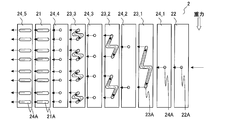
- FIG. 3 is a development view of a stacked header of the heat exchanger according to the first embodiment.
- FIG. 3 is a development view of a stacked header of the heat exchanger according to the first embodiment. It is a figure which shows the modification of the flow path formed in the 3rd plate-shaped member of the heat exchanger which concerns on Embodiment 1.
- FIG. It is a perspective view in the state which decomposed
- FIG. 3 is a development view of a stacked header of the heat exchanger according to the first embodiment. It is a figure which shows the comparative example of the flow path formed in the 3rd plate-shaped member of the heat exchanger which concerns on Embodiment 1.
- FIG. 6 is a diagram showing a specific example-1 of a flow path formed in a third plate-like member of the heat exchanger according to Embodiment 1.
- FIG. 10 is a diagram showing the effect of Example-1 of the flow path formed in the third plate-like member of the heat exchanger according to Embodiment 1.
- FIG. 6 is a diagram showing a specific example-2 of the flow path formed in the third plate-like member of the heat exchanger according to the first embodiment.
- FIG. 6 is a diagram showing a specific example-2 of the flow path formed in the third plate-like member of the heat exchanger according to the first embodiment.
- FIG. 6 is a diagram showing a specific example-3 of the flow path formed in the third plate-like member of the heat exchanger according to the first embodiment.
- FIG. 10 is a diagram showing a specific example-5 of the flow path formed in the third plate-like member of the heat exchanger according to the first embodiment.
- FIG. 6 is a diagram showing the state of the refrigerant of Specific Example-5 of the flow path formed in the third plate-like member of the heat exchanger according to Embodiment 1.
- FIG. 8 is a diagram showing a specific example-6 of the flow path formed in the third plate-like member of the heat exchanger according to the first embodiment.
- FIG. 6 is a perspective view of a modified example-1 of the heat exchanger according to Embodiment 1 in a state where a stacked header is disassembled.
- FIG. 6 is a perspective view of a modified example-1 of the heat exchanger according to Embodiment 1 in a state where a stacked header is disassembled.
- FIG. 10 is a perspective view of a modified example-2 of the heat exchanger according to the first embodiment in a state where a stacked header is disassembled.
- FIG. 10 is a perspective view of a modified example-3 of the heat exchanger according to the first embodiment in a state in which the stacked header is disassembled.
- FIG. 9 is a development view of a stacked header in Modification-3 of the heat exchanger according to Embodiment 1.
- FIG. 12 is a perspective view of a modified example-4 of the heat exchanger according to Embodiment 1 in a state where a stacked header is disassembled.
- FIG. 10 is a perspective view of a main part and a cross-sectional view of the main part in a state in which the stacked header is disassembled in Modification-5 of the heat exchanger according to the first embodiment.
- FIG. 7 is a perspective view of a main part and a cross-sectional view of the main part in a state in which a laminated header is disassembled in Modification-6 of the heat exchanger according to the first embodiment.
- FIG. 10 is a diagram showing a specific example of the flow path formed in the third plate-like member of Modification-6 of the heat exchanger according to Embodiment 1.
- FIG. 10 is a perspective view of a modified example-7 of the heat exchanger according to Embodiment 1 in a state where a stacked header is disassembled. It is a figure which shows the structure of the heat exchanger which concerns on Embodiment 2.
- FIG. It is a perspective view in the state which decomposed
- FIG. It is an expanded view of the laminated header of the heat exchanger which concerns on Embodiment 2.
- FIG. 10 is a diagram showing a specific example of the flow path formed in the third plate-like member of Modification-6 of the heat exchanger according to Embodiment 1.
- FIG. 10 is a perspective view of a modified example-7 of the heat exchanger according to Embodiment 1 in a state where a stacked header is disassembled
- FIG. 6 is a development view of a stacked header of a heat exchanger according to Embodiment 3.
- FIG. It is a figure which shows the structure of the air conditioning apparatus to which the heat exchanger which concerns on Embodiment 3 is applied.
- the laminated header according to the present invention will be described with reference to the drawings.
- the laminated header according to the present invention distributes the refrigerant flowing into the heat exchanger
- a refrigerant may be distributed.
- the configuration, operation, and the like described below are merely examples, and are not limited to such configuration, operation, and the like.
- symbol is attached
- symbol is abbreviate
- the illustration of the fine structure is simplified or omitted as appropriate.
- overlapping or similar descriptions are appropriately simplified or omitted.
- the general resistance acting on the refrigerant passing through the flow path is defined as “flow resistance”, and the components attributed to the characteristics (shape, surface properties, etc.) of the flow path in the “flow resistance”. , Defined as “channel resistance”.
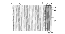
- FIG. 1 is a diagram illustrating a configuration of a heat exchanger according to the first embodiment.
- the heat exchanger 1 includes a stacked header 2, a header 3, a plurality of first heat transfer tubes 4, a holding member 5, and a plurality of fins 6.
- the laminated header 2 has a refrigerant inflow portion 2A and a plurality of refrigerant outflow portions 2B.
- the header 3 has a plurality of refrigerant inflow portions 3A and a refrigerant outflow portion 3B.
- Refrigerant piping is connected to the refrigerant inflow portion 2A of the stacked header 2 and the refrigerant outflow portion 3B of the header 3.
- a plurality of first heat transfer tubes 4 are connected between the plurality of refrigerant outflow portions 2B of the stacked header 2 and the plurality of refrigerant inflow portions 3A of the header 3.
- the first heat transfer tube 4 is a flat tube in which a plurality of flow paths are formed.
- the first heat transfer tube 4 is made of, for example, aluminum.
- the ends of the plurality of first heat transfer tubes 4 on the stacked header 2 side are connected to the plurality of refrigerant outflow portions 2B of the stacked header 2 while being held by the plate-like holding member 5.
- the holding member 5 is made of aluminum, for example.
- a plurality of fins 6 are joined to the first heat transfer tube 4.
- the fin 6 is made of aluminum, for example.
- the first heat transfer tube 4 and the fin 6 may be joined by brazing.
- the case where the 1st heat exchanger tube 4 is eight is shown in FIG. 1, it is not limited to such a case.
- the refrigerant flowing through the refrigerant pipe flows into the stacked header 2 through the refrigerant inflow portion 2A and is distributed, and flows out to the plurality of first heat transfer tubes 4 through the plurality of refrigerant outflow portions 2B.
- the refrigerant exchanges heat with, for example, air supplied by a fan in the plurality of first heat transfer tubes 4.
- the refrigerant flowing through the plurality of first heat transfer tubes 4 flows into and merges with the header 3 through the plurality of refrigerant inflow portions 3A, and flows out into the refrigerant pipe through the refrigerant outflow portion 3B.
- the refrigerant can flow backward.
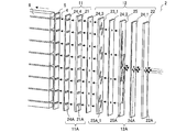
- FIG. 2 is a perspective view of the heat exchanger according to Embodiment 1 in a state where the stacked header is disassembled.
- the stacked header 2 includes a first plate-like body 11 and a second plate-like body 12. The first plate-like body 11 and the second plate-like body 12 are stacked.
- the first plate 11 is stacked on the refrigerant outflow side.
- the first plate-like body 11 has a first plate-like member 21.
- a plurality of first outlet channels 11A are formed in the first plate-like body 11.
- the plurality of first outlet channels 11A correspond to the plurality of refrigerant outflow portions 2B in FIG.
- a plurality of flow paths 21A are formed in the first plate-like member 21.
- the plurality of flow paths 21 ⁇ / b> A are through-holes having an inner peripheral surface along the outer peripheral surface of the first heat transfer tube 4.
- several flow path 21A functions as several 1st exit flow path 11A.
- the first plate-like member 21 is, for example, about 1 to 10 mm in thickness and made of aluminum.
- the end of the first heat transfer tube 4 protrudes from the surface of the holding member 5, the first plate 11 is laminated on the holding member 5, and the inner periphery of the first outlet channel 11 ⁇ / b> A is formed on the outer peripheral surface of the end.
- the first heat transfer tube 4 is connected to the first outlet channel 11A.
- the first outlet channel 11A and the first heat transfer tube 4 may be positioned by, for example, fitting between a convex portion formed in the holding member 5 and a concave portion formed in the first plate body 11, In such a case, the end of the first heat transfer tube 4 may not protrude from the surface of the holding member 5.
- the holding member 5 may not be provided, and the first heat transfer tube 4 may be directly connected to the first outlet channel 11A. In such a case, parts costs and the like are reduced.
- the second plate-like body 12 is laminated on the refrigerant inflow side.
- the second plate-like body 12 includes a second plate-like member 22 and a plurality of third plate-like members 23_1 to 23_3.
- a distribution channel 12A is formed in the second plate-like body 12.
- the distribution flow path 12A includes a first inlet flow path 12a and a plurality of branch flow paths 12b.
- the first inlet channel 12a corresponds to the refrigerant inflow portion 2A in FIG.
- a flow path 22A is formed in the second plate-like member 22.
- the flow path 22A is a circular through hole.
- the flow path 22A functions as the first inlet flow path 12a.
- the second plate-like member 22 has a thickness of about 1 to 10 mm and is made of aluminum.
- a base or the like is provided on the surface of the second plate-like member 22 on the refrigerant inflow side, and the refrigerant pipe is connected to the first inlet channel 12a via the base or the like.
- the inner peripheral surface of the first inlet channel 12a has a shape that fits with the outer peripheral surface of the refrigerant pipe, and the refrigerant pipe may be directly connected to the first inlet channel 12a without using a base or the like. In such a case, parts costs and the like are reduced.
- a plurality of flow paths 23A_1 to 23A_3 are formed in the plurality of third plate-like members 23_1 to 23_3.
- the plurality of flow paths 23A_1 to 23A_3 are through grooves. Details of the plurality of flow paths 23A_1 to 23A_3 will be described later.
- each of the plurality of flow paths 23A_1 to 23A_3 functions as the branch flow path 12b.
- the plurality of third plate-like members 23_1 to 23_3 are, for example, about 1 to 10 mm in thickness and made of aluminum. In the case where the plurality of flow paths 23A_1 to 23A_3 are formed by pressing or the like, the processing is simplified and the manufacturing cost and the like are reduced.
- the plurality of third plate members 23_1 to 23_3 may be collectively referred to as the third plate member 23 in some cases.
- the plurality of flow paths 23A_1 to 23A_3 may be collectively referred to as a flow path 23A.
- the holding member 5, the first plate member 21, the second plate member 22, and the third plate member 23 may be collectively referred to as a plate member.
- the branch flow path 12b branches the flowing refrigerant into two and flows out. Therefore, when the number of first heat transfer tubes 4 to be connected is eight, at least three third plate members 23 are required. When there are 16 first heat transfer tubes 4 to be connected, at least four third plate members 23 are required.
- the number of connected first heat transfer tubes 4 is not limited to a power of 2. In such a case, the branched flow path 12b and the non-branched flow path may be combined. Two first heat transfer tubes 4 may be connected.
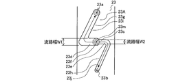
- FIG. 3 is a development view of the stacked header of the heat exchanger according to the first embodiment.
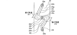
- the flow path 23 ⁇ / b> A formed in the third plate-like member 23 has a shape that connects the end portion 23 a and the end portion 23 b via a straight line portion 23 c.
- the straight line portion 23c is substantially perpendicular to the direction of gravity.
- a region of the flow path 23A that communicates between the end 23a and the opening 23f is defined as a first flow path 23g, and a region that communicates between the end 23b and the opening 23f is defined as a second flow path. 23h.
- the end 23a is on the upper side compared to the opening 23f
- the end 23b is on the lower side compared to the opening 23f. Since the straight line connecting the end portion 23a and the end portion 23b is parallel to the longitudinal direction of the third plate-like member 23, it is possible to reduce the dimension in the short direction of the third plate-like member 23, and the component Cost, weight, etc. are reduced. Furthermore, since the straight line connecting the end 23a and the end 23b is parallel to the arrangement direction of the first heat transfer tubes 4, the heat exchanger 1 is saved in space.
- FIG. 4 is a development view of the stacked header of the heat exchanger according to the first embodiment.
- the longitudinal direction of the third plate-like member 23 and the straight portion 23c are It will not be vertical.
- the stacked header 2 is not limited to one in which the plurality of first outlet channels 11A are arranged along the direction of gravity.
- a wall-mounted room air conditioner indoor unit, an air conditioner outdoor unit, a chiller outdoor unit It may be used when the heat exchanger 1 is disposed at an inclination like a heat exchanger such as a machine.
- FIG. 1 is a development view of the stacked header of the heat exchanger according to the first embodiment.
- the longitudinal direction of the cross section of the channel 21 ⁇ / b> A formed in the first plate member 21, that is, the longitudinal direction of the cross section of the first outlet channel 11 ⁇ / b> A is the longitudinal direction of the first plate member 21.
- the longitudinal direction of the cross section of 11 A of 1st exit flow paths may be perpendicular
- the flow path 23A is branched as a through groove having a shape in which connecting portions 23i and 23j connecting the end 23d and the end 23e of the straight portion 23c and the end 23a and the end 23b are branched. Another channel may be communicated with the channel 12b. When no other flow path is communicated with the branch flow path 12b, it is ensured that the uniformity of refrigerant distribution is improved.
- the connecting portions 23i and 23j may be straight lines or curved lines.
- FIG. 5 is a view showing a modification of the flow path formed in the third plate-like member of the heat exchanger according to the first embodiment.
- the flow path 23A may not have the straight portion 23c.
- the horizontal portion between the end 23a and the end 23b of the flow path 23A that is substantially perpendicular to the direction of gravity is the opening 23f.
- the straight portion 23c is provided, when the refrigerant branches at the opening 23f, the angle of each branching direction with respect to the direction of gravity becomes uniform, and it is difficult to be affected by gravity.
- the straight portion 23c When the straight portion 23c is not provided, it is more susceptible to the influence of gravity than when the straight portion 23c is provided, but the flow resistance acting on the refrigerant passing through the first flow path 23g and the second flow path 23h. Since the difference from the flow resistance acting on the refrigerant passing through is reduced, the uniformity of refrigerant distribution can be improved.
- each of the end portion 23a and the end portion 23b and the connection portions 23i and 23j are communicated with each other via linear portions 23k and 23l parallel to the direction of gravity. May be.
- the straight portions 23k and 23l When communicating via the straight portions 23k and 23l, the drift that occurs when the refrigerant passes through the connecting portions 23i and 23j that are not parallel to the direction of gravity is made uniform, and the distribution of the refrigerant is uniform. Can be improved.
- the refrigerant that has flowed into the opening 23f of the flow path 23A formed in the third plate-like member 23_2 hits the surface of the adjacent laminated member, and the end 23d and the end 23e of the linear portion 23c It branches into two toward each.
- the branched refrigerant reaches the end portions 23a and 23b of the flow path 23A and flows into the opening 23f of the flow path 23A formed in the third plate member 23_3.
- the refrigerant that has flowed into the opening 23f of the flow path 23A formed in the third plate-like member 23_3 hits the surface of the adjacent laminated member, and the end portion 23d and the end portion 23e of the linear portion 23c It branches into two toward each.
- the branched refrigerant reaches the end portions 23 a and 23 b of the flow path 23 ⁇ / b> A, passes through the flow path 21 ⁇ / b> A of the first plate-like member 21, and flows into the first heat transfer tube 4.
- Each plate-like member is preferably laminated by brazing joint.
- a brazing material for joining may be supplied by using a double-sided clad material obtained by rolling a brazing material on both sides for all plate-like members or every other plate-like member.
- a brazing material for joining may be supplied to all the plate-like members by using a one-side clad material in which the brazing material is rolled on one side.
- the brazing material sheet may be supplied by laminating brazing material sheets between the plate-like members.
- the brazing material may be supplied by applying a pasty brazing material between the plate members.
- the brazing material may be supplied by laminating clad materials obtained by rolling the brazing material on both sides between the plate-like members.
- the plate-like members are laminated without gaps, leakage of the refrigerant is suppressed, and pressure resistance is ensured.
- the occurrence of brazing defects is further suppressed.
- processing that promotes the formation of fillets, such as formation of ribs is performed at locations where refrigerant leakage is likely to occur, the occurrence of brazing defects is further suppressed.
- the first heat transfer tubes 4 and the fins 6 are made of the same material (for example, made of aluminum), it is possible to braze and join together. , Productivity is improved.
- the first heat transfer tubes 4 and the fins 6 may be brazed.
- only the first plate 11 may be brazed to the holding member 5 first, and the second plate 12 may be brazed afterwards.
- FIG. 6 is a perspective view of the heat exchanger according to Embodiment 1 in a state in which the stacked header is disassembled.
- FIG. 7 is a development view of the stacked header of the heat exchanger according to the first embodiment.
- a brazing material is preferably supplied by laminating a platy member obtained by rolling a brazing material on both sides, that is, clad materials on both sides, between the respective platy members.
- a plurality of clad members 24_1 to 24_5 are laminated between the respective plate-like members.
- the plurality of both-side clad materials 24_1 to 24_5 may be collectively referred to as the both-side clad material 24.
- the clad material 24 may be laminated between some plate-like members, and the brazing material may be supplied between other plate-like members by other methods.
- the both-side clad material 24 has a channel 24A that penetrates the both-side clad material 24 in a region facing a region where the refrigerant flows out of a channel formed in a plate-like member laminated adjacent to the side into which the refrigerant flows. Is formed.
- the flow path 24A formed in the both-side clad material 24 laminated on the second plate member 22 and the third plate member 23 is a circular through hole.
- the flow path 24 ⁇ / b> A formed in the both-side clad material 24 ⁇ / b> _ ⁇ b> 5 laminated between the first plate-like member 21 and the holding member 5 is a through hole having an inner peripheral surface along the outer peripheral surface of the first heat transfer tube 4. .
- the flow path 24A functions as a refrigerant isolation flow path for the first outlet flow path 11A and the distribution flow path 12A.
- the end portion of the first heat transfer tube 4 may or may not project from the surface of the both-side clad material 24_5.
- the flow path 24A is formed by pressing or the like, the processing is simplified and the manufacturing cost and the like are reduced.
- all the members to be brazed including the clad members 24 are made of the same material (for example, made of aluminum), it is possible to collectively braze and improve productivity.
- the refrigerant isolation flow path By forming the refrigerant isolation flow path by the both-side clad material 24, in particular, it is possible to ensure the isolation of the refrigerant that branches off from the branch flow path 12b and flows out. Moreover, the run-up distance until it flows into the branch flow path 12b and the first outlet flow path 11A can be ensured by the thickness of each clad member 24, and the uniformity of refrigerant distribution is improved. Moreover, the design freedom of the branch flow path 12b is improved by ensuring the isolation between the refrigerants.
- FIG. 8 is a diagram showing a comparative example of the flow path formed in the third plate-like member of the heat exchanger according to the first embodiment.
- stacked adjacently is shown with the dotted line.
- the state where the clad members 24 are laminated on the third plate-like member 23 (the state shown in FIGS. 6 and 7) is shown, the same applies to the state where the clad members 24 are not laminated (the state shown in FIGS. 2 and 3). It is.
- the first flow path 23g and the second flow path 23h have the same flow path resistance and are point-symmetric about the opening 23f, and the flow path 23A of the third plate-like member 23. Will be described.
- the difference in height between the end 23a and the center 23m of the opening 23f is defined as the flow path height h1
- the difference in height between the end 23b and the center 23m of the opening 23f is defined as The flow path height h2
- the channel width W1, the channel width of the second channel 23h, the channel width W2, the bending angle of the first channel 23g, the bending angle ⁇ 1, and the bending angle of the second channel 23h are defined as the bending angle ⁇ 2.
- the thickness of the third plate-like member 23, that is, the flow path depth is defined as ⁇ .
- coolant of the 1st flow path 23g flows out is defined as the edge part 23a
- coolant of the 2nd flow path 23h flows out is defined as the edge part 23b.
- the surface texture of the first flow path 23g is equal to the surface texture of the second flow path 23h.
- the pressure of the refrigerant flowing into the opening 23f is the pressure P0
- the pressure of the refrigerant flowing out from the end 23a is the pressure P1
- the pressure of the refrigerant flowing out from the end 23b is the pressure P2
- the first flow path 23g is defined as pressure loss ⁇ Pf1
- the pressure loss due to the flow path resistance in the second flow path 23h is defined as pressure loss ⁇ Pf2.
- the pressure P1 of the refrigerant flowing out from the end 23a and the pressure P2 of the refrigerant flowing out from the end 23b are calculated by the following (formula 1) and (formula 2) using the refrigerant density ⁇ [kg / m 3 ]. Is done.
- the pressure P1 of the refrigerant flowing out from the end portion 23a and the pressure P2 of the refrigerant flowing out from the end portion 23b are the flow resistance of the first flow path 23g, that is, the pressure loss generated in the refrigerant passing through the first flow path 23g ( ⁇ Pf1 + ⁇ ⁇ g ⁇ h1) is different from the flow resistance of the second flow path 23h, that is, the pressure loss ( ⁇ Pf2 ⁇ ⁇ g ⁇ h2) generated in the refrigerant passing through the second flow path 23h.
- the flow rate of the refrigerant flowing out from the end portion 23a and the flow rate of the refrigerant flowing out from the end portion 23b are not uniform.
- the pressure loss ⁇ Pf1 due to the flow resistance in the first flow path 23g and the pressure loss ⁇ Pf2 due to the flow resistance in the second flow path 23h are the friction coefficient ⁇ 1 [dimensionalless] of the first flow path 23g.
- the pressure loss ⁇ Pf1 due to the flow resistance in the first flow path 23g and the pressure loss ⁇ Pf2 due to the flow resistance in the second flow path 23h are Since the parameters include the channel lengths l1 and l2, the channel widths W1 and W2, the friction coefficients ⁇ 1 and ⁇ 2, and the like, the pressure loss generated in the refrigerant passing through the first channel 23g by changing them ( The difference between ⁇ Pf1 + ⁇ ⁇ g ⁇ h1) and the pressure loss ( ⁇ Pf2 ⁇ ⁇ g ⁇ h2) generated in the refrigerant passing through the second flow path 23h can be reduced.
- the difference between ( ⁇ Pf2 ⁇ ⁇ g ⁇ h2) can be reduced.
- the flow path 23A of the third plate-like member 23 has the same flow path resistances of the first flow path 23g and the second flow path 23h as shown in the following specific example, and the first flow path. 23g and the second flow path 23h are improved so that the difference in flow resistance between the first flow path 23g and the second flow path 23h is smaller than the state where the opening 23f is point-symmetric.
- the flow rate of the refrigerant flowing out from the end portion 23a and the flow rate of the refrigerant flowing out from the end portion 23b are made uniform, and the distribution uniformity of the refrigerant in the stacked header 2 is improved.
- the specific examples may be combined.
- FIG. 9 is a diagram showing a specific example-1 of the flow path formed in the third plate-like member of the heat exchanger according to the first embodiment.
- the flow path width W2 of the second flow path 23h is narrower than the flow path width W1 of the first flow path 23g.
- the flow path resistance of the second flow path 23h becomes larger than the flow path resistance of the first flow path 23g, and the refrigerant flowing into the second flow path 23h due to the influence of gravity. An increase in the flow rate is suppressed.
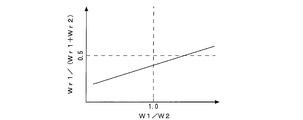
- FIG. 10 is a diagram illustrating an effect of the specific example-1 of the flow path formed in the third plate-like member of the heat exchanger according to the first embodiment.
- the flow rate of the refrigerant flowing through the first flow path 23g is defined as Wr1
- the flow rate of the refrigerant flowing through the second flow path 23h is defined as Wr2.
- Wr1 of the refrigerant flowing through the refrigerant is smaller than the flow rate Wr2 of the refrigerant flowing through the second flow path 23h.
- the first flow path 23g having the flow rate Wr1 of the refrigerant flowing through the first flow path 23g is reduced.
- the ratio with respect to the sum of the flow rate Wr1 of the flowing refrigerant and the flow rate Wr2 of the refrigerant flowing through the second flow path 23h can be close to 0.5.
- FIG. 11 is a diagram showing a specific example-2 of the flow path formed in the third plate-like member of the heat exchanger according to the first embodiment.
- the flow path length l2 of the second flow path 23h is longer than the flow path length l1 of the first flow path 23g.
- the flow path resistance of the second flow path 23h becomes larger than the flow path resistance of the first flow path 23g, and the refrigerant flowing into the second flow path 23h due to the influence of gravity.
- An increase in the flow rate is suppressed.
- the effect of the specific example-2 is the same as that in which the horizontal axis in FIG. 9 is l2 / l1.
- FIG. 12 is a diagram showing a specific example-2 of the flow path formed in the third plate-like member of the heat exchanger according to the first embodiment.
- the channel length l2 of the second channel 23h is set to the first flow rate with the channel height h1 of the first channel 23g equal to the channel height h2 of the second channel 23h.
- the flow path height h2 of the second flow path 23h is set to the flow path height of the first flow path 23g.
- the channel length l2 of the second channel 23h may be made longer than the channel length l1 of the first channel 23g.
- the channel height h2 of the second channel 23h is set to the first channel 23g so that the sum of the channel height h1 of the first channel 23g and the channel height h2 of the second channel 23h does not change. And the sum of the channel height h1 of the first channel 23g and the channel height h2 of the second channel 23h may be changed.
- the channel height h2 of the second channel 23h may be set higher than the channel height h1 of the first channel 23g.
- the flow path height h2 of the second flow path 23h is set so that the sum of the flow path height h1 of the first flow path 23g and the flow path height h2 of the second flow path 23h is reduced.
- the flow path height h2 of the second flow path 23h is set to the first flow so that the sum of the flow path height h1 of the first flow path 23g and the flow path height h2 of the second flow path 23h is increased. You may make it high compared with the flow path height h1 of the path
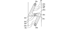
- FIG. 13 is a diagram showing a specific example-3 of the flow path formed in the third plate-like member of the heat exchanger according to the first embodiment.
- the second flow path 23h is formed with a convex portion 23n protruding inside the flow path.
- the convex portion 23n is an annular stop, a hemispherical protrusion, or the like.
- the cross-sectional area of the second flow path 23h becomes narrow, and the flow path resistance of the second flow path 23h becomes larger than the flow path resistance of the first flow path 23g. Due to the influence, an increase in the flow rate of the refrigerant flowing into the second flow path 23h is suppressed.
- the convex portion 23n may be formed by inserting a convex portion formed on a member laminated adjacently into the flow path 23A.
- the first flow path 23g may be formed with a protrusion having a small protrusion amount compared to the protrusion 23n formed in the second flow path 23h.
- FIG. 14 is a diagram showing a specific example-5 of the flow path formed in the third plate-like member of the heat exchanger according to the first embodiment.
- FIG. 15 is a diagram showing the state of the refrigerant in Concrete Example-5 of the flow path formed in the third plate-like member of the heat exchanger according to Embodiment 1.
- FIG. 15A shows a case where the bending angle ⁇ 2 of the second flow path 23h is small
- FIG. 15B shows a case where the bending angle ⁇ 2 of the second flow path 23h is large.
- the bending angle ⁇ 2 of the second flow path 23h is larger than the bending angle ⁇ 1 of the first flow path 23g.
- FIG. 16 is a diagram showing a specific example-6 of the flow path formed in the third plate-like member of the heat exchanger according to the first embodiment.
- the flow path 23 ⁇ / b> A is inclined so that the straight line portion 23 c becomes higher from the direction perpendicular to the gravity direction by the inclination angle ⁇ ⁇ b> 3 on the second flow path 23 h side.
- the refrigerant flowing through the first flow path 23g uses gravity, and the refrigerant flowing through the second flow path 23h opposes gravity, so the second flow path 23h
- the flow path resistance of the first flow path 23g is larger than the flow path resistance of the first flow path 23g, and the flow rate of the refrigerant flowing into the second flow path 23h due to the influence of gravity is suppressed.
- the flow path 23A may not have the straight portion 23c, the first flow path 23g communicates with the opening 23f from the lower side of the opening 23f, and the second The flow path 23h may communicate with the opening 23f from above the opening 23f.
- FIG. 17 is a diagram illustrating a configuration of an air-conditioning apparatus to which the heat exchanger according to Embodiment 1 is applied.
- the air conditioner 51 includes a compressor 52, a four-way valve 53, a heat source side heat exchanger 54, a throttle device 55, a load side heat exchanger 56, a heat source side fan 57, A load-side fan 58 and a control device 59.
- the compressor 52, the four-way valve 53, the heat source side heat exchanger 54, the expansion device 55, and the load side heat exchanger 56 are connected by refrigerant piping to form a refrigerant circulation circuit.
- a compressor 52, a four-way valve 53, a throttle device 55, a heat source side fan 57, a load side fan 58, various sensors, and the like are connected to the control device 59.
- the heat source side heat exchanger 54 acts as a condenser during the cooling operation, and acts as an evaporator during the heating operation.
- the load side heat exchanger 56 acts as an evaporator during the cooling operation, and acts as a condenser during the heating operation.
- the flow of the refrigerant during the cooling operation will be described.
- the high-pressure and high-temperature gas refrigerant discharged from the compressor 52 flows into the heat source side heat exchanger 54 via the four-way valve 53 and condenses by heat exchange with the outside air supplied by the heat source side fan 57. It becomes a high-pressure liquid refrigerant and flows out of the heat source side heat exchanger 54.
- the high-pressure liquid refrigerant flowing out of the heat source side heat exchanger 54 flows into the expansion device 55 and becomes a low-pressure gas-liquid two-phase refrigerant.
- the low-pressure gas-liquid two-phase refrigerant flowing out of the expansion device 55 flows into the load-side heat exchanger 56 and evaporates by heat exchange with the indoor air supplied by the load-side fan 58, thereby causing a low-pressure gas state. And flows out of the load-side heat exchanger 56.
- the low-pressure gaseous refrigerant flowing out from the load-side heat exchanger 56 is sucked into the compressor 52 through the four-way valve 53.
- the flow of the refrigerant during the heating operation will be described.
- the high-pressure and high-temperature gas refrigerant discharged from the compressor 52 flows into the load-side heat exchanger 56 through the four-way valve 53 and condenses by heat exchange with the indoor air supplied by the load-side fan 58. And becomes a high-pressure liquid refrigerant and flows out of the load-side heat exchanger 56.
- the high-pressure liquid refrigerant flowing out of the load-side heat exchanger 56 flows into the expansion device 55 and becomes a low-pressure gas-liquid two-phase refrigerant.
- the low-pressure gas-liquid two-phase refrigerant that flows out of the expansion device 55 flows into the heat source side heat exchanger 54 and evaporates by heat exchange with the outside air supplied by the heat source side fan 57, so that the low-pressure gas state It becomes a refrigerant and flows out of the heat source side heat exchanger 54.
- the low-pressure gaseous refrigerant flowing out from the heat source side heat exchanger 54 is sucked into the compressor 52 through the four-way valve 53.
- the heat exchanger 1 is used for at least one of the heat source side heat exchanger 54 and the load side heat exchanger 56.
- the heat exchanger 1 is connected so that the refrigerant flows in from the stacked header 2 and the refrigerant flows out of the header 3 when the heat exchanger 1 acts as an evaporator. That is, when the heat exchanger 1 acts as an evaporator, the gas-liquid two-phase refrigerant flows from the refrigerant pipe to the stacked header 2, and the gas refrigerant flows from the first heat transfer pipe 4 to the header 3. .
- the heat exchanger 1 acts as a condenser, a gaseous refrigerant flows from the refrigerant pipe to the header 3, and a liquid refrigerant flows from the first heat transfer tube 4 to the stacked header 2.
- the flow path 23A formed in the third plate member 23 is a through groove, and the third flow path 12b is formed by stacking the third plate members 23. Therefore, processing and assembly are simplified, and production efficiency and manufacturing cost are reduced.
- the heat exchanger 1 when used in an inclined state, that is, even when the arrangement direction of the first outlet channel 11A intersects the direction of gravity, the flow rate of the refrigerant flowing out from the end 23a and out from the end 23b.
- the flow rate of the refrigerant is made uniform, and the uniformity of refrigerant distribution in the stacked header 2 is improved.
- the circumferential direction is perpendicular to the refrigerant inflow direction.
- the stacked header 2 does not have to be enlarged in the entire circumferential direction perpendicular to the refrigerant inflow direction, and the heat exchanger 1 is saved in space.
- the heat transfer tube when the heat transfer tube is changed from a circular tube to a flat tube, the flow passage cross-sectional area in the heat transfer tube is reduced, and the pressure loss generated in the heat transfer tube increases.
- the laminated header 2 is not limited to the case where the first heat transfer tube 4 is a flat tube.
- FIG. 18 is a perspective view of a modified example-1 of the heat exchanger according to Embodiment 1 in a state where the stacked header is disassembled.
- 18 and the subsequent drawings show a state in which both side clad materials 24 are laminated (states in FIGS. 6 and 7), but a state in which both side clad materials 24 are not laminated (states in FIGS. 2 and 3). Needless to say, it may be.
- a plurality of flow paths 22A are formed in the second plate-shaped member 22, that is, a plurality of first inlet flow paths 12a are formed in the second plate-shaped body 12, and a third plate-shaped member is formed.
- the number of 23 sheets may be reduced. By being configured in this way, parts cost, weight, etc. are reduced.
- FIG. 19 is a perspective view of a modified example-1 of the heat exchanger according to Embodiment 1 in a state where the stacked header is disassembled.
- the plurality of flow paths 22 ⁇ / b> A may not be provided in the area facing the area where the refrigerant flows in the flow path 23 ⁇ / b> A formed in the third plate-like member 23.
- a plurality of flow paths 22 ⁇ / b> A are collectively formed in one place, and the other plate-like member 25 stacked between the second plate-like member 22 and the third plate-like member 23 ⁇ / b> _ ⁇ b> 1.
- Each of the refrigerants that have passed through the plurality of flow paths 22A may be guided to a region facing the region where the refrigerant flows in the flow channel 23A formed in the third plate member 23 by the flow channel 25A.
- FIG. 20 is a perspective view of a modification 2 of the heat exchanger according to Embodiment 1 in a state where the stacked header is disassembled.
- any one of the third plate-like members 23 may be replaced with another plate-like member 25 in which a channel 25B in which the opening 23f is not located in the straight portion 23c is formed.
- the opening 23f is positioned not at the straight portion 23c but at the intersection, and the refrigerant flows into the intersection and branches into four.
- the number of branches may be any number. As the number of branches increases, the number of third plate-like members 23 is reduced. Although configured in this way, the uniformity of refrigerant distribution is reduced, but the parts cost, weight, and the like are reduced.
- FIG. 21 is a perspective view of the modification 3 of the heat exchanger according to Embodiment 1 in a state where the stacked header is disassembled.
- FIG. 22 is a development view of the multilayer header of Modification-3 of the heat exchanger according to Embodiment 1. In FIG. 22, the illustration of the clad material 24 on both sides is omitted. As shown in FIGS. 21 and 22, any one of the third plate-like members 23 (for example, the third plate-like member 23_2) flows out the refrigerant without folding back to the side where the first plate-like body 11 is present.
- the third plate-like members 23 for example, the third plate-like member 23_2
- the channel 23B has the same configuration as the channel 23A. That is, the flow path 23B has a straight portion 23c perpendicular to the direction of gravity, and the refrigerant flows from the opening 23f between the end 23d and the end 23e of the straight portion 23c, and the end 23d and the end The liquid flows out from the end portions 23a and 23b of the flow path 23B through each of the portions 23e.
- the third plate-like member 23 (for example, the third plate-like member 23_1) stacked on the opposite side of the third plate-like member 23 where the first plate-like body 11 is provided is formed as a flow passage. There may be a flow path 23C for returning the refrigerant flowing in from 23B without branching to the flow path 23A of the third plate-like member 23 in which the flow path 23B is formed. May be.
- FIG. 23 is a perspective view of the modification 4 of the heat exchanger according to Embodiment 1 in a state where the stacked header is disassembled.
- a convex portion 26 may be formed on the surface of either the plate-like member or the both-side clad material 24, that is, any of the laminated members.
- the convex portion 26 may be a component such as a spacer.
- a concave portion 27 into which the convex portion 26 is inserted is formed in a member laminated adjacently.
- the recess 27 may or may not be a through hole.
- the convex portion 26 and the concave portion 27 may be fitted.
- a plurality of convex portions 26 and concave portions 27 may be formed, and the stacked members may be positioned by the fitting.
- the recessed part 27 is not formed, but the convex part 26 may be inserted in a part of flow path formed in the member laminated
- the height, size, and the like of the convex portion 26 may be set to such an extent that the refrigerant flow is not hindered.
- FIG. 24 is a perspective view of a main part and a cross-sectional view of the main part in a state where the laminated header is disassembled in Modification-5 of the heat exchanger according to the first embodiment.
- 24A is a perspective view of the main part in a state in which the laminated header is disassembled
- FIG. 24B is a first plate-like member taken along the line AA in FIG. 24A.
- any of the plurality of flow paths 21A formed in the first plate member 21 is circular on the surface of the first plate member 21 on the side where the second plate body 12 is present.
- the taper-shaped through-hole which becomes a shape along the outer peripheral surface of the 1st heat exchanger tube 4 in the surface in the side with the holding member 5 of the 1st plate-shaped member 21 may be sufficient.
- the through hole gradually extends from the surface on the side with the second plate 12 to the surface on the side with the holding member 5. It becomes a spreading shape. With this configuration, the pressure loss of the refrigerant when passing through the first outlet channel 11A is reduced.
- FIG. 25 is a perspective view of a main part and a cross-sectional view of the main part in a state where the stacked header is disassembled in Modification-6 of the heat exchanger according to the first embodiment.
- 25 (a) is a perspective view of the main part in a state where the stacked header is disassembled
- FIG. 25 (b) is a third plate-like member taken along line BB of FIG. 25 (a).
- FIG. 25 As shown in FIG. 25, any of the flow paths 23A formed in the third plate-like member 23 may be a bottomed groove. In such a case, a circular through hole 23q is formed in each of the end 23o and the end 23p on the bottom surface of the groove of the flow path 23A.
- FIG. 25 shows the case where the refrigerant outflow side of the flow path 23A is the bottom surface, but the refrigerant inflow side of the flow path 23A may be the bottom surface. In such a case, a through hole may be formed in a region corresponding to the opening 23f.
- FIG. 26 is a diagram showing a specific example of the flow path formed in the third plate-like member of Modification-6 of the heat exchanger according to Embodiment 1.
- FIG. 26B is a cross-sectional view of the third plate-like member 23 taken along the line CC in FIG.
- the channel depth ⁇ 2 of the second channel 23h is shallower than the channel depth ⁇ 1 of the first channel 23g.
- the flow path resistance of the second flow path 23h becomes larger than the flow path resistance of the first flow path 23g, and the refrigerant flowing into the second flow path 23h due to the influence of gravity.
- An increase in the flow rate is suppressed.
- the effect is the same as that in which the horizontal axis in FIG.
- the flow path 23A may have the same mode as in the first specific example to the sixth specific example, and the flow path depth ⁇ 2 of the second flow path 23h is set to the flow path depth ⁇ 1 of the first flow path 23g. It is possible to combine the shallowing with those modes.
- the first flow path 23g and the second flow path 23h may be formed as a through groove, and a member that fills a part of the through groove in the depth direction may be inserted only into the second flow path 23h.
- the member may be a convex portion formed on a member laminated adjacently.
- FIG. 27 is a perspective view of Modified Example-7 of the heat exchanger according to Embodiment 1 in a state where the stacked header is disassembled.
- the flow path 22A functioning as the first inlet flow path 12a is formed in a laminated member other than the second plate-like member 22, that is, other plate-like members, both-side clad members 24, and the like. May be.
- the flow path 22A may be, for example, a through hole that penetrates from the side surface of another plate-like member to the surface on the side where the second plate-like member 22 is present.
- the present invention includes those in which the first inlet channel 12 a is formed in the first plate-like body 11, and the “distribution channel” of the present invention has the first inlet channel 12 a as the second plate-like body 12. Other than the distribution flow path 12A formed in the above.
- FIG. 28 is a diagram illustrating a configuration of a heat exchanger according to the second embodiment.
- the heat exchanger 1 includes a stacked header 2, a plurality of first heat transfer tubes 4, a holding member 5, and a plurality of fins 6.
- the stacked header 2 has a refrigerant inflow portion 2A, a plurality of refrigerant outflow portions 2B, a plurality of refrigerant inflow portions 2C, and a refrigerant outflow portion 2D.
- a refrigerant pipe is connected to the refrigerant inflow portion 2A of the multilayer header 2 and the refrigerant outflow portion 2D of the multilayer header 2.
- the first heat transfer tube 4 is a flat tube that has been subjected to hairpin bending.
- a plurality of first heat transfer tubes 4 are connected between the plurality of refrigerant outflow portions 2B of the multilayer header 2 and the plurality of refrigerant inflow portions 2C of the multilayer header 2.
- the refrigerant flowing through the refrigerant pipe flows into the stacked header 2 through the refrigerant inflow portion 2A and is distributed, and flows out to the plurality of first heat transfer tubes 4 through the plurality of refrigerant outflow portions 2B.
- the refrigerant exchanges heat with, for example, air supplied by a fan in the plurality of first heat transfer tubes 4.
- the refrigerant that has passed through the plurality of first heat transfer tubes 4 flows into and merges with the stacked header 2 through the plurality of refrigerant inflow portions 2C, and flows out to the refrigerant piping through the refrigerant outflow portion 2D.
- the refrigerant can flow backward.
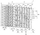
- FIG. 29 is a perspective view of the heat exchanger according to Embodiment 2 in a state where the stacked header is disassembled.
- FIG. 30 is a development view of the stacked header of the heat exchanger according to the second embodiment. In FIG. 30, the illustration of the clad material 24 on both sides is omitted.
- the stacked header 2 includes a first plate-like body 11 and a second plate-like body 12. The first plate-like body 11 and the second plate-like body 12 are stacked.
- the first plate 11 is formed with a plurality of first outlet channels 11A and a plurality of second inlet channels 11B.
- the plurality of second inlet channels 11B correspond to the plurality of refrigerant inflow portions 2C in FIG.
- a plurality of flow paths 21B are formed in the first plate-like member 21.
- the plurality of flow paths 21 ⁇ / b> B are through-holes having an inner peripheral surface along the outer peripheral surface of the first heat transfer tube 4.
- several flow path 21B functions as several 2nd inlet flow path 11B.
- a distribution channel 12A and a merging channel 12B are formed in the second plate-like body 12.
- the merging channel 12B includes a mixing channel 12c and a second outlet channel 12d.
- the second outlet channel 12d corresponds to the refrigerant outflow portion 2D in FIG.
- a flow path 22B is formed in the second plate-like member 22 in the second plate-like member 22 .
- the flow path 22B is a circular through hole.
- the flow path 22B functions as the second outlet flow path 12d.
- a plurality of the flow paths 22B, that is, the second outlet flow paths 12d may be formed.
- a plurality of flow paths 23D_1 to 23D_3 are formed in the plurality of third plate-like members 23_1 to 23_3.
- the plurality of flow paths 23D_1 to 23D_3 are rectangular through holes penetrating substantially the entire area of the third plate member 23 in the height direction.
- each of the plurality of flow paths 23D_1 to 23D_3 functions as the mixing flow path 12c.
- the plurality of flow paths 23D_1 to 23D_3 do not have to be rectangular.
- the plurality of flow paths 23D_1 to 23D_3 may be collectively referred to as a flow path 23D.
- the brazing material is supplied by laminating the clad material 24 on both sides of which the brazing material is rolled on both sides between the plate-like members.
- the flow path 24 ⁇ / b> B formed in the both-side clad material 24 ⁇ / b> _ ⁇ b> 5 laminated between the holding member 5 and the first plate-like member 21 is a through hole whose inner peripheral surface follows the outer peripheral surface of the first heat transfer tube 4. .
- the flow path 24B formed in the both-side clad material 24_4 laminated between the first plate member 21 and the third plate member 23_3 is a circular through hole.
- the flow path 24B formed in the both-side clad material 24 laminated on the other third plate-like member 23 and the second plate-like member 22 has a rectangular shape penetrating almost the entire area of the both-side clad material 24 in the height direction. Is a hole.
- the flow path 24B functions as a refrigerant isolation flow path for the second inlet flow path 11B and the merge flow path 12B.
- the flow path 22B functioning as the second outlet flow path 12d may be formed in other plate-like members other than the second plate-like member 22 of the second plate-like body 12, both-side clad material 24, and the like. In such a case, it is only necessary to form a cutout that communicates a part of the flow path 23D or the flow path 24B with, for example, the other plate-like member or the side surfaces of the clad members 24 on both sides.
- the flow path 22B which functions as the 2nd exit flow path 12d may be formed in the 1st plate-shaped member 21 by folding the mixing flow path 12c.
- the present invention includes the one in which the second outlet channel 12d is formed in the first plate-like body 11, and the “merging channel” of the present invention has the second outlet channel 12d in the second plate-like body 12. Other than the merging channel 12B formed in the above.
- FIG. 31 is a diagram illustrating a configuration of an air-conditioning apparatus to which the heat exchanger according to Embodiment 2 is applied.
- the heat exchanger 1 is used for at least one of the heat source side heat exchanger 54 and the load side heat exchanger 56.
- the heat exchanger 1 when the heat exchanger 1 acts as an evaporator, the refrigerant flows into the first heat transfer tube 4 from the distribution flow path 12 ⁇ / b> A of the stacked header 2, and the stacked header 2 is transferred from the first heat transfer tube 4.
- the refrigerant flows into the merging flow path 12B.
- a gas-liquid two-phase refrigerant flows from the refrigerant pipe into the distribution flow path 12A of the laminated header 2 and flows from the first heat transfer tube 4 to the laminated header 2.
- the refrigerant in the gas state flows into the merge channel 12B.
- a gaseous refrigerant flows from the refrigerant pipe into the merged flow path 12B of the laminated header 2 and the distribution flow path of the laminated header 2 from the first heat transfer pipe 4. Liquid refrigerant flows into 12A.
- FIG. 32 is a diagram illustrating a configuration of a heat exchanger according to the third embodiment.
- the heat exchanger 1 includes a stacked header 2, a plurality of first heat transfer tubes 4, a plurality of second heat transfer tubes 7, a holding member 5, and a plurality of fins 6. Have.
- the laminated header 2 has a plurality of refrigerant folding portions 2E. Similar to the first heat transfer tube 4, the second heat transfer tube 7 is a flat tube that has been subjected to hairpin bending. A plurality of first heat transfer tubes 4 are connected between the plurality of refrigerant outflow portions 2B and the plurality of refrigerant folding portions 2E of the multilayer header 2, and the plurality of refrigerant folding portions 2E and the plurality of refrigerant inflows of the multilayer header 2 are connected. A plurality of second heat transfer tubes 7 are connected between the portion 2C.
- the refrigerant flowing through the refrigerant pipe flows into the stacked header 2 through the refrigerant inflow portion 2A and is distributed, and flows out to the plurality of first heat transfer tubes 4 through the plurality of refrigerant outflow portions 2B.
- the refrigerant exchanges heat with, for example, air supplied by a fan in the plurality of first heat transfer tubes 4.
- the refrigerant that has passed through the plurality of first heat transfer tubes 4 flows into the plurality of refrigerant folding portions 2 ⁇ / b> E of the stacked header 2, is turned back, and flows out to the plurality of second heat transfer tubes 7.
- the refrigerant exchanges heat with, for example, air supplied by a fan in the plurality of second heat transfer tubes 7.
- the refrigerant that has passed through the plurality of second heat transfer tubes 7 flows into and merges with the stacked header 2 via the plurality of refrigerant inflow portions 2C, and flows out to the refrigerant piping via the refrigerant outflow portion 2D.
- the refrigerant can flow backward.
- FIG. 33 is a perspective view of the heat exchanger according to Embodiment 3 in a state where the stacked header is disassembled.
- FIG. 34 is a development view of the stacked header of the heat exchanger according to the third embodiment. In FIG. 34, the illustration of the clad members 24 on both sides is omitted.
- the stacked header 2 includes a first plate-like body 11 and a second plate-like body 12. The first plate-like body 11 and the second plate-like body 12 are stacked.
- first plate-like body 11 a plurality of first outlet channels 11A, a plurality of second inlet channels 11B, and a plurality of folded channels 11C are formed.
- the plurality of folding channels 11C correspond to the plurality of refrigerant folding sections 2E in FIG.
- a plurality of flow paths 21 ⁇ / b> C are formed in the first plate-like member 21.
- the plurality of flow paths 21 ⁇ / b> C have through-holes whose inner peripheral surfaces surround the outer peripheral surface of the refrigerant outflow side end of the first heat transfer tube 4 and the outer peripheral surface of the second heat transfer tube 7 on the refrigerant inflow side. It is.
- the plurality of channels 21C function as the plurality of folded channels 11C.
- the brazing material is supplied by laminating the clad material 24 on both sides of which the brazing material is rolled on both sides between the plate-like members.
- the flow path 24C formed in the both-side clad material 24_5 laminated between the holding member 5 and the first plate-like member 21 has an inner peripheral surface that is the outer peripheral surface of the end of the first heat transfer tube 4 on the refrigerant outflow side. And a through hole having a shape surrounding the outer peripheral surface of the end of the second heat transfer tube 7 on the refrigerant inflow side.
- the refrigerant that has flowed into the flow path 21 ⁇ / b> B of the first plate-shaped member 21 flows into the flow path 23 ⁇ / b> D formed in the third plate-shaped member 23 and is mixed therewith.
- the mixed refrigerant passes through the flow path 22B of the second plate-like member 22 and flows out to the refrigerant pipe.
- FIG. 35 is a diagram illustrating a configuration of an air-conditioning apparatus to which the heat exchanger according to Embodiment 3 is applied.
- the heat exchanger 1 is used for at least one of the heat source side heat exchanger 54 and the load side heat exchanger 56.
- the refrigerant flows into the first heat transfer tube 4 from the distribution flow path 12 ⁇ / b> A of the stacked header 2 and from the second heat transfer tube 7 to the stacked header 2.
- the refrigerant flows into the merging flow path 12B.
- a gas-liquid two-phase refrigerant flows from the refrigerant pipe into the distribution flow path 12A of the laminated header 2 and flows from the second heat transfer tube 7 to the laminated header 2.
- the refrigerant in the gas state flows into the merge channel 12B.
- a gaseous refrigerant flows from the refrigerant pipe into the merged flow path 12B of the laminated header 2 and the distribution flow path of the laminated header 2 from the first heat transfer pipe 4. Liquid refrigerant flows into 12A.
- the heat exchanger 1 acts as a condenser
- the first heat transfer tube 4 is compared with the second heat transfer tube 7 on the upstream side (windward side) of the airflow generated by the heat source side fan 57 or the load side fan 58. )
- the heat exchanger 1 is disposed. That is, the refrigerant flow from the second heat transfer tube 7 to the first heat transfer tube 4 and the airflow face each other.
- the refrigerant of the first heat transfer tube 4 has a lower temperature than the refrigerant of the second heat transfer tube 7.
- the airflow generated by the heat source side fan 57 or the load side fan 58 has a lower temperature on the upstream side of the heat exchanger 1 than on the downstream side of the heat exchanger 1.
- the refrigerant can be supercooled (so-called SC) with a low-temperature airflow flowing upstream of the heat exchanger 1, and the condenser performance is improved.
- SC supercooled
- the heat source side fan 57 and the load side fan 58 may be provided on the leeward side or may be provided on the leeward side.
- the number of rows of heat transfer tubes is increased as in the heat exchanger 1, the heat exchange amount is increased without changing the area of the heat exchanger 1 as viewed from the front, the interval between the fins 6 and the like. It is possible to make it.
- the number of rows of heat transfer tubes becomes two, the amount of heat exchange increases by about 1.5 times or more. Note that the number of rows of heat transfer tubes may be three or more. Furthermore, the area of the heat exchanger 1 as viewed from the front, the interval between the fins 6 and the like may be changed.
- a header (laminated header 2) is provided only on one side of the heat exchanger 1.
- laminated header 2 is provided only on one side of the heat exchanger 1.
- header stacked header 2
- the degree of freedom in design, production efficiency, etc. Is improved.
- the first heat transfer tube 4 is located on the windward side as compared to the second heat transfer tube 7.
- headers laminated header 2 and header 3
- condensation is performed by giving a temperature difference of the refrigerant for each row of heat transfer tubes. It was difficult to improve the vessel performance.
- the first heat transfer tube 4 and the second heat transfer tube 7 are flat tubes, unlike a circular tube, the degree of freedom of bending is low, so that a temperature difference of the refrigerant is given to each row of heat transfer tubes. It is difficult to realize by deforming the refrigerant flow path.
Landscapes
- Engineering & Computer Science (AREA)
- Physics & Mathematics (AREA)
- Thermal Sciences (AREA)
- Mechanical Engineering (AREA)
- General Engineering & Computer Science (AREA)
- Heat-Exchange Devices With Radiators And Conduit Assemblies (AREA)
Abstract
Description
なお、以下では、本発明に係る積層型ヘッダーが、熱交換器に流入する冷媒を分配するものである場合を説明しているが、本発明に係る積層型ヘッダーが、他の機器に流入する冷媒を分配するものであってもよい。また、以下で説明する構成、動作等は、一例にすぎず、そのような構成、動作等に限定されない。また、各図において、同一又は類似するものには、同一の符号を付すか、又は、符号を付すことを省略している。また、細かい構造については、適宜図示を簡略化又は省略している。また、重複又は類似する説明については、適宜簡略化又は省略している。
実施の形態1に係る熱交換器について説明する。
<熱交換器の構成>
以下に、実施の形態1に係る熱交換器の構成について説明する。
図1は、実施の形態1に係る熱交換器の、構成を示す図である。
図1に示されるように、熱交換器1は、積層型ヘッダー2と、ヘッダー3と、複数の第1伝熱管4と、保持部材5と、複数のフィン6と、を有する。
以下に、実施の形態1に係る熱交換器における冷媒の流れについて説明する。
冷媒配管を流れる冷媒は、冷媒流入部2Aを介して積層型ヘッダー2に流入して分配され、複数の冷媒流出部2Bを介して複数の第1伝熱管4に流出する。冷媒は、複数の第1伝熱管4において、例えば、ファンによって供給される空気等と熱交換する。複数の第1伝熱管4を流れる冷媒は、複数の冷媒流入部3Aを介してヘッダー3に流入して合流し、冷媒流出部3Bを介して冷媒配管に流出する。冷媒は、逆流することができる。
以下に、実施の形態1に係る熱交換器の積層型ヘッダーの構成について説明する。
図2は、実施の形態1に係る熱交換器の、積層型ヘッダーを分解した状態での斜視図である。
図2に示されるように、積層型ヘッダー2は、第1板状体11と、第2板状体12と、を有する。第1板状体11と第2板状体12とは、積層される。
図3に示されるように、第3板状部材23に形成された流路23Aは、端部23aと端部23bとの間を、直線部23cを介して結ぶ形状である。直線部23cは、重力方向とほぼ垂直である。流路23Aが、冷媒の流入側に隣接して積層される部材によって、直線部23cの端部23dと端部23eとの間の一部の領域23f(以降、開口部23fという)以外の領域を閉塞され、冷媒の流出側に隣接して積層される部材によって、端部23a及び端部23b以外の領域を閉塞されることで、分岐流路12bが形成される。流路23Aの、端部23aと開口部23fとの間を連通する領域が、第1流路23gと定義され、端部23bと開口部23fとの間を連通する領域が、第2流路23hと定義される。
図4に示されるように、第1伝熱管4の配列方向が、重力方向と平行ではない、つまり重力方向と交差する場合には、第3板状部材23の長手方向と直線部23cとが垂直にならない。つまり、積層型ヘッダー2は、複数の第1出口流路11Aが、重力方向に沿って配列されるものに限定されず、例えば、壁掛けタイプのルームエアコン室内機、空調機用室外機、チラー室外機等の熱交換器のように、熱交換器1が傾斜して配設される場合に用いられてもよい。なお、図4では、第1板状部材21に形成された流路21Aの断面の長手方向、つまり、第1出口流路11Aの断面の長手方向が、第1板状部材21の長手方向と垂直である場合を示しているが、第1出口流路11Aの断面の長手方向が、重力方向と垂直であってもよい。
図5(a)に示されるように、流路23Aは、直線部23cを有しなくてもよい。そのような場合には、流路23Aの、端部23aと端部23bとの間の、重力方向とほぼ垂直な水平部が、開口部23fとなる。直線部23cを有する場合には、冷媒が開口部23fで分岐する際に、各分岐方向の重力方向に対する角度が均一になって、重力の影響を受け難くなる。直線部23cを有しない場合には、直線部23cを有する場合と比較して、重力の影響を受け易くなるが、第1流路23gを通過する冷媒に作用する流れ抵抗と第2流路23hを通過する冷媒に作用する流れ抵抗との差が小さくされているため、冷媒の分配の均一性を向上することができる。
以下に、実施の形態1に係る熱交換器の積層型ヘッダーにおける冷媒の流れについて説明する。
図3及び図4に示されるように、第2板状部材22の流路22Aを通過した冷媒は、第3板状部材23_1に形成された流路23Aの開口部23fに流入する。開口部23fに流入した冷媒は、隣接して積層される部材の表面に当たり、直線部23cの端部23dと端部23eとのそれぞれに向かって2つに分岐する。分岐された冷媒は、流路23Aの端部23a、23bに至り、第3板状部材23_2に形成された流路23Aの開口部23fに流入する。
以下に、実施の形態1に係る熱交換器の積層型ヘッダーの各板状部材の積層方法について説明する。
各板状部材は、ロウ付け接合によって積層されるとよい。全ての板状部材又は1つおきの板状部材に、ロウ材が両面に圧延加工された両側クラッド材が用いられることで、接合のためのロウ材が供給されてもよい。全ての板状部材に、ロウ材が片面に圧延加工された片側クラッド材が用いられることで、接合のためのロウ材が供給されてもよい。各板状部材の間に、ロウ材シートが積層されることで、ロウ材が供給されてもよい。各板状部材の間に、ペースト状のロウ材が塗布されることで、ロウ材が供給されてもよい。各板状部材の間に、ロウ材が両面に圧延加工された両側クラッド材が積層されることで、ロウ材が供給されてもよい。
特に、各板状部材の間に、ロウ材が両面に圧延加工された板状部材、つまり両側クラッド材が積層されることで、ロウ材が供給されるとよい。図6及び図7に示されるように、複数の両側クラッド材24_1~24_5が、各板状部材間に積層される。以下では、複数の両側クラッド材24_1~24_5を総称して、両側クラッド材24と記載する場合がある。なお、一部の板状部材の間に、両側クラッド材24が積層され、他の板状部材の間に、他の方法によってロウ材が供給されてもよい。
図8は、実施の形態1に係る熱交換器の、第3板状部材に形成される流路の比較例を示す図である。なお、図8では、隣接して積層される部材に形成される流路の一部を点線で示している。第3板状部材23に両側クラッド材24が積層される状態(図6及び図7の状態)を示しているが、両側クラッド材24が積層されない状態(図2及び図3の状態)でも同様である。
まず、比較例として、第1流路23gと第2流路23hとが、流路抵抗が互いに等しく、開口部23fを中心として点対称である場合の、第3板状部材23の流路23Aについて説明する。



図9は、実施の形態1に係る熱交換器の、第3板状部材に形成される流路の具体例-1を示す図である。
図9に示されるように、流路23Aは、第2流路23hの流路幅W2が、第1流路23gの流路幅W1と比較して、狭い。そのような場合には、第2流路23hの流路抵抗が、第1流路23gの流路抵抗と比較して、大きくなり、重力の影響によって、第2流路23hに流入する冷媒の流量が大きくなることが抑制される。
図10に示されるように、第1流路23gの流路幅W1と第2流路23hの流路幅W2とが等しい、つまりW1/W2が1.0であると、第1流路23gを流れる冷媒の流量Wr1は、第2流路23hを流れる冷媒の流量Wr2と比較して小さくなる。第2流路23hの流路幅W2を、第1流路23gの流路幅W1と比較して狭くすることで、第1流路23gを流れる冷媒の流量Wr1の、第1流路23gを流れる冷媒の流量Wr1と第2流路23hを流れる冷媒の流量Wr2との和に対する比率を、0.5に近づけることができる。
図11は、実施の形態1に係る熱交換器の、第3板状部材に形成される流路の具体例-2を示す図である。
図11に示されるように、流路23Aは、第2流路23hの流路長l2が、第1流路23gの流路長l1と比較して、長い。そのような場合には、第2流路23hの流路抵抗が、第1流路23gの流路抵抗と比較して、大きくなり、重力の影響によって、第2流路23hに流入する冷媒の流量が大きくなることが抑制される。具体例-2の効果は、図9の横軸を、l2/l1としたものと同様である。
図11では、第1流路23gの流路高さh1と第2流路23hの流路高さh2とを、等しくした状態で、第2流路23hの流路長l2を、第1流路23gの流路長l1と比較して長くする場合を示しているが、図12に示されるように、第2流路23hの流路高さh2を、第1流路23gの流路高さh1と比較して高くすることで、第2流路23hの流路長l2を、第1流路23gの流路長l1と比較して長くしてもよい。
図13は、実施の形態1に係る熱交換器の、第3板状部材に形成される流路の具体例-3を示す図である。
図13に示されるように、流路23Aは、第2流路23hに、流路の内側に突出する凸部23nが形成される。凸部23nは、環状の絞り、半球状の突起等である。そのような場合には、第2流路23hの断面積が狭くなって、第2流路23hの流路抵抗が、第1流路23gの流路抵抗と比較して、大きくなり、重力の影響によって、第2流路23hに流入する冷媒の流量が大きくなることが抑制される。凸部23nが、隣接して積層される部材に形成された凸部が流路23Aに挿入されることで、形成されてもよい。なお、第1流路23gに、第2流路23hに形成された凸部23nと比較して突出量が小さい凸部が形成されてもよい。
流路23Aは、第2流路23hの表面粗さRa2が、第1流路23gの表面粗さRa1と比較して、大きい。そのような場合には、第2流路23hの摩擦係数λ2が大きくなって、第2流路23hの流路抵抗が、第1流路23gの流路抵抗と比較して、大きくなり、重力の影響によって、第2流路23hに流入する冷媒の流量が大きくなることが抑制される。具体例-4の効果は、図9の横軸を、Ra2/Ra1としたものと同様である。
図14は、実施の形態1に係る熱交換器の、第3板状部材に形成される流路の具体例-5を示す図である。図15は、実施の形態1に係る熱交換器の、第3板状部材に形成される流路の具体例-5の冷媒の状態を示す図である。なお、図15(a)は、第2流路23hの曲げ角度θ2が、小さい場合を示し、図15(b)は、第2流路23hの曲げ角度θ2が、大きい場合を示している。
図14に示されるように、流路23Aは、第2流路23hの曲げ角度θ2が、第1流路23gの曲げ角度θ1と比較して、大きい。図15に示されるように、曲げ部の外側及び曲げ部の冷媒が流出する側の内側において、冷媒の流れが乱されて渦が生じる。第2流路23hの曲げ角度θ2が、第1流路23gの曲げ角度θ1と比較して大きい場合には、第2流路23hにおいて、冷媒の流れが乱される領域が大きくなって、渦の影響が大きくなるため、第2流路23hの流路抵抗が、第1流路23gの流路抵抗と比較して、大きくなり、重力の影響によって、第2流路23hに流入する冷媒の流量が大きくなることが抑制される。具体例-5の効果は、図9の横軸を、θ2/θ1としたものと同様である。
図16は、実施の形態1に係る熱交換器の、第3板状部材に形成される流路の具体例-6を示す図である。
図16に示されるように、流路23Aは、直線部23cが、重力方向と垂直な方向から傾き角度θ3だけ、第2流路23h側が高くなるように傾斜する。そのような場合には、直線部23cにおいて、第1流路23gを流れる冷媒が、重力を利用し、第2流路23hを流れる冷媒が、重力に逆らうこととなるため、第2流路23hの流路抵抗が、第1流路23gの流路抵抗と比較して、大きくなり、重力の影響によって、第2流路23hに流入する冷媒の流量が大きくなることが抑制される。図5(a)に示されるように、流路23Aが、直線部23cを有しなくてもよく、第1流路23gが、開口部23fに開口部23fの下側から連通し、第2流路23hが、開口部23fに開口部23fの上側から連通すればよい。
以下に、実施の形態1に係る熱交換器の使用態様の一例について説明する。
なお、以下では、実施の形態1に係る熱交換器が空気調和装置に使用される場合を説明しているが、そのような場合に限定されず、例えば、冷媒循環回路を有する他の冷凍サイクル装置に使用されてもよい。また、空気調和装置が、冷房運転と暖房運転とを切り替えるものである場合を説明しているが、そのような場合に限定されず、冷房運転又は暖房運転のみを行うものであってもよい。
図17に示されるように、空気調和装置51は、圧縮機52と、四方弁53と、熱源側熱交換器54と、絞り装置55と、負荷側熱交換器56と、熱源側ファン57、負荷側ファン58、制御装置59と、を有する。圧縮機52と四方弁53と熱源側熱交換器54と絞り装置55と負荷側熱交換器56とが冷媒配管で接続されて、冷媒循環回路が形成される。
圧縮機52から吐出される高圧高温のガス状態の冷媒は、四方弁53を介して熱源側熱交換器54に流入し、熱源側ファン57によって供給される外気との熱交換によって凝縮することで高圧の液状態の冷媒となり、熱源側熱交換器54から流出する。熱源側熱交換器54から流出した高圧の液状態の冷媒は、絞り装置55に流入し、低圧の気液二相状態の冷媒となる。絞り装置55から流出する低圧の気液二相状態の冷媒は、負荷側熱交換器56に流入し、負荷側ファン58によって供給される室内空気との熱交換によって蒸発することで低圧のガス状態の冷媒となり、負荷側熱交換器56から流出する。負荷側熱交換器56から流出する低圧のガス状態の冷媒は、四方弁53を介して圧縮機52に吸入される。
圧縮機52から吐出される高圧高温のガス状態の冷媒は、四方弁53を介して負荷側熱交換器56に流入し、負荷側ファン58によって供給される室内空気との熱交換によって凝縮することで高圧の液状態の冷媒となり、負荷側熱交換器56から流出する。負荷側熱交換器56から流出した高圧の液状態の冷媒は、絞り装置55に流入し、低圧の気液二相状態の冷媒となる。絞り装置55から流出する低圧の気液二相状態の冷媒は、熱源側熱交換器54に流入し、熱源側ファン57によって供給される外気との熱交換によって蒸発することで低圧のガス状態の冷媒となり、熱源側熱交換器54から流出する。熱源側熱交換器54から流出する低圧のガス状態の冷媒は、四方弁53を介して圧縮機52に吸入される。
以下に、実施の形態1に係る熱交換器の作用について説明する。
第3板状部材23の流路23Aは、第1流路23gと第2流路23hとの流路抵抗が互いに等しく、且つ、第1流路23gと第2流路23hとが開口部23fを中心として点対称である状態と比較して、第1流路23gと第2流路23hとの流れ抵抗の差が小さい。そのため、端部23aから流出する冷媒の流量と端部23bから流出する冷媒の流量とが均一化されて、積層型ヘッダー2の冷媒の分配の均一性が向上される。
図18は、実施の形態1に係る熱交換器の変形例-1の、積層型ヘッダーを分解した状態での斜視図である。なお、図18以下の図面では、両側クラッド材24が積層される状態(図6及び図7の状態)を示しているが、両側クラッド材24が積層されない状態(図2及び図3の状態)であってもよいことは、言うまでもない。
図18に示されるように、第2板状部材22に流路22Aが複数形成されて、つまり、第2板状体12に第1入口流路12aが複数形成されて、第3板状部材23の枚数が削減されてもよい。このように構成されることで、部品費、重量等が削減される。
複数の流路22Aが、第3板状部材23に形成される流路23Aの冷媒が流入する領域と対向する領域に設けられなくてもよい。図19に示されるように、例えば、複数の流路22Aが一箇所に纏めて形成され、第2板状部材22と第3板状部材23_1との間に積層される他の板状部材25の流路25Aによって、複数の流路22Aを通過した冷媒のそれぞれが、第3板状部材23に形成される流路23Aの冷媒が流入する領域と対向する領域に導かれてもよい。
図20は、実施の形態1に係る熱交換器の変形例-2の、積層型ヘッダーを分解した状態での斜視図である。
図20に示されるように、第3板状部材23のいずれか1つが、開口部23fが直線部23cに位置しない流路25Bが形成された他の板状部材25に、置き換えられてもよい。例えば、流路25Bは、開口部23fが直線部23cではなく交差部に位置し、冷媒はその交差部に流入して4つに分岐する。分岐の数は、どのような数でもよい。分岐の数が多い程、第3板状部材23の枚数が削減される。このように構成されることで、冷媒の分配の均一性は低下してしまうものの、部品費、重量等が削減される。
図21は、実施の形態1に係る熱交換器の変形例-3の、積層型ヘッダーを分解した状態での斜視図である。図22は、実施の形態1に係る熱交換器の変形例-3の、積層型ヘッダーの展開図である。なお、図22では、両側クラッド材24の図示が省略されている。
図21及び図22に示されるように、第3板状部材23のいずれか1つ(例えば、第3板状部材23_2)が、冷媒を第1板状体11が有る側に折り返さずに流出する分岐流路12bとして機能する流路23Aと、冷媒を第1板状体11が有る側の反対側に折り返して流出する分岐流路12bとして機能する流路23Bと、を有してもよい。流路23Bは、流路23Aと同様の構成である。つまり、流路23Bは、重力方向と垂直な直線部23cを有し、冷媒は、直線部23cの端部23dと端部23eとの間の開口部23fから流入し、その端部23dと端部23eとのそれぞれを経由して、流路23Bの端部23a、23bから流出する。このように構成されることで、第3板状部材23の枚数が削減され、部品費、重量等が削減される。また、ロウ付け不良の発生の頻度が削減される。
図23は、実施の形態1に係る熱交換器の変形例-4の、積層型ヘッダーを分解した状態での斜視図である。
図23に示されるように、板状部材及び両側クラッド材24のいずれか、つまり積層される部材のいずれかの表面に、凸部26が形成されてもよい。凸部26は、例えば、位置、形状、大きさ等が、積層される部材毎に固有である。凸部26は、スペーサ等の部品であってもよい。隣接して積層される部材には、凸部26が挿入される凹部27が形成される。凹部27は、貫通穴であってもよく、そうでなくてもよい。このように構成されることで、積層される部材の積層順序を間違うことが抑制され、不良率が低減される。凸部26と凹部27とが嵌合してもよい。そのような場合には、凸部26と凹部27とが、複数形成され、積層される部材がその嵌合によって位置決めされてもよい。また、凹部27が形成されず、凸部26が、隣接して積層される部材に形成される流路の一部に挿入されてもよい。そのような場合には、凸部26の高さ、大きさ等を、冷媒の流れを妨げない程度とすればよい。
図24は、実施の形態1に係る熱交換器の変形例-5の、積層型ヘッダーを分解した状態での要部の斜視図と要部の断面図である。なお、図24(a)は、積層型ヘッダーを分解した状態での要部の斜視図であり、図24(b)は、図24(a)のA-A線での第1板状部材21の断面図である。
図24に示されるように、第1板状部材21に形成された複数の流路21Aのいずれかが、第1板状部材21の第2板状体12の有る側の表面で円形状になり、第1板状部材21の保持部材5の有る側の表面で第1伝熱管4の外周面に沿う形状になる、テーパ状の貫通穴であってもよい。特に、第1伝熱管4が扁平管である場合には、その貫通穴は、第2板状体12の有る側の表面から保持部材5の有る側の表面に至るまでの間で、徐々に広がる形状となる。このように構成されることで、第1出口流路11Aを通過する際の冷媒の圧力損失が低減される。
図25は、実施の形態1に係る熱交換器の変形例-6の、積層型ヘッダーを分解した状態での要部の斜視図と要部の断面図である。なお、図25(a)は、積層型ヘッダーを分解した状態での要部の斜視図であり、図25(b)は、図25(a)のB-B線での第3板状部材23の断面図である。
図25に示されるように、第3板状部材23に形成された流路23Aのいずれかが、有底の溝であってもよい。そのような場合には、流路23Aの溝の底面の端部23oと端部23pとのそれぞれに円形状の貫通穴23qが形成される。このように構成されることで、分岐流路12b間に冷媒隔離流路として機能する流路24Aを介在させるために、板状部材間に両側クラッド材24が積層されなくてもよくなり、生産効率が向上される。なお、図25では、流路23Aの冷媒の流出側が底面である場合を示しているが、流路23Aの冷媒の流入側が底面であってもよい。そのような場合には、開口部23fに相当する領域に貫通穴が形成されればよい。
図26に示されるように、流路23Aは、第2流路23hの流路深さδ2が、第1流路23gの流路深さδ1と比較して、浅い。そのような場合には、第2流路23hの流路抵抗が、第1流路23gの流路抵抗と比較して、大きくなり、重力の影響によって、第2流路23hに流入する冷媒の流量が大きくなることが抑制される。その効果は、図9の横軸を、δ1/δ2としたものと同様である。なお、流路23Aは、具体例1~具体例6と同様の態様であってもよく、また、第2流路23hの流路深さδ2を、第1流路23gの流路深さδ1と比較して浅くすることと、それらの態様と、が組み合わされてもよい。
図27は、実施の形態1に係る熱交換器の変形例-7の、積層型ヘッダーを分解した状態での斜視図である。
図27に示されるように、第1入口流路12aとして機能する流路22Aは、第2板状部材22以外の積層される部材、つまり、他の板状部材、両側クラッド材24等に形成されてもよい。そのような場合には、流路22Aを、例えば、他の板状部材の側面から第2板状部材22の有る側の表面までを貫通する貫通穴とすればよい。つまり、本発明は、第1入口流路12aが第1板状体11に形成されるものを含み、本発明の「分配流路」は、第1入口流路12aが第2板状体12に形成される分配流路12A以外を含む。
実施の形態2に係る熱交換器について説明する。
なお、実施の形態1と重複又は類似する説明は、適宜簡略化又は省略している。
<熱交換器の構成>
以下に、実施の形態2に係る熱交換器の構成について説明する。
図28は、実施の形態2に係る熱交換器の、構成を示す図である。
図28に示されるように、熱交換器1は、積層型ヘッダー2と、複数の第1伝熱管4と、保持部材5と、複数のフィン6と、を有する。
以下に、実施の形態2に係る熱交換器における冷媒の流れについて説明する。
冷媒配管を流れる冷媒は、冷媒流入部2Aを介して積層型ヘッダー2に流入して分配され、複数の冷媒流出部2Bを介して複数の第1伝熱管4に流出する。冷媒は、複数の第1伝熱管4において、例えば、ファンによって供給される空気等と熱交換する。複数の第1伝熱管4を通過した冷媒は、複数の冷媒流入部2Cを介して積層型ヘッダー2に流入して合流し、冷媒流出部2Dを介して冷媒配管に流出する。冷媒は、逆流することができる。
以下に、実施の形態2に係る熱交換器の積層型ヘッダーの構成について説明する。
図29は、実施の形態2に係る熱交換器の、積層型ヘッダーを分解した状態での斜視図である。図30は、実施の形態2に係る熱交換器の、積層型ヘッダーの展開図である。なお、図30では、両側クラッド材24の図示が省略されている。
図29及び図30に示されるように、積層型ヘッダー2は、第1板状体11と、第2板状体12と、を有する。第1板状体11と第2板状体12とは、積層される。
以下に、実施の形態2に係る熱交換器の積層型ヘッダーにおける冷媒の流れについて説明する。
図29及び図30に示されるように、第1板状部材21の流路21Aから流出して第1伝熱管4を通過した冷媒は、第1板状部材21の流路21Bに流入する。第1板状部材21の流路21Bに流入した冷媒は、第3板状部材23に形成された流路23Dに流入して混合される。混合された冷媒は、第2板状部材22の流路22Bを通過して、冷媒配管に流出する。
以下に、実施の形態2に係る熱交換器の使用態様の一例について説明する。
図31は、実施の形態2に係る熱交換器が適用される空気調和装置の、構成を示す図である。
図31に示されるように、熱源側熱交換器54及び負荷側熱交換器56の少なくともいずれか一方に、熱交換器1が用いられる。熱交換器1は、熱交換器1が蒸発器として作用する際に、積層型ヘッダー2の分配流路12Aから第1伝熱管4に冷媒が流入し、第1伝熱管4から積層型ヘッダー2の合流流路12Bに冷媒が流入するように接続される。つまり、熱交換器1が蒸発器として作用する際は、冷媒配管から積層型ヘッダー2の分配流路12Aに気液二相状態の冷媒が流入し、第1伝熱管4から積層型ヘッダー2の合流流路12Bにガス状態の冷媒が流入する。また、熱交換器1が凝縮器として作用する際は、冷媒配管から積層型ヘッダー2の合流流路12Bにガス状態の冷媒が流入し、第1伝熱管4から積層型ヘッダー2の分配流路12Aに液状態の冷媒が流入する。
以下に、実施の形態2に係る熱交換器の作用について説明する。
積層型ヘッダー2では、第1板状体11に複数の第2入口流路11Bが形成され、第2板状体12に合流流路12Bが形成される。そのため、ヘッダー3が不要となって、熱交換器1の部品費等が削減される。また、ヘッダー3が不要となる分、第1伝熱管4を延長してフィン6の枚数等を増加する、つまり熱交換器1の熱交換部の実装体積を増加することが可能となる。
実施の形態3に係る熱交換器について説明する。
なお、実施の形態1及び実施の形態2と重複又は類似する説明は、適宜簡略化又は省略している。
<熱交換器の構成>
以下に、実施の形態3に係る熱交換器の構成について説明する。
図32は、実施の形態3に係る熱交換器の、構成を示す図である。
図32に示されるように、熱交換器1は、積層型ヘッダー2と、複数の第1伝熱管4と、複数の第2伝熱管7と、保持部材5と、複数のフィン6と、を有する。
以下に、実施の形態3に係る熱交換器における冷媒の流れについて説明する。
冷媒配管を流れる冷媒は、冷媒流入部2Aを介して積層型ヘッダー2に流入して分配され、複数の冷媒流出部2Bを介して複数の第1伝熱管4に流出する。冷媒は、複数の第1伝熱管4において、例えば、ファンによって供給される空気等と熱交換する。複数の第1伝熱管4を通過した冷媒は、積層型ヘッダー2の複数の冷媒折返部2Eに流入して折り返され、複数の第2伝熱管7に流出する。冷媒は、複数の第2伝熱管7において、例えば、ファンによって供給される空気等と熱交換する。複数の第2伝熱管7を通過した冷媒は、複数の冷媒流入部2Cを介して積層型ヘッダー2に流入して合流し、冷媒流出部2Dを介して冷媒配管に流出する。冷媒は、逆流することができる。
以下に、実施の形態3に係る熱交換器の積層型ヘッダーの構成について説明する。
図33は、実施の形態3に係る熱交換器の、積層型ヘッダーを分解した状態での斜視図である。図34は、実施の形態3に係る熱交換器の、積層型ヘッダーの展開図である。なお、図34では、両側クラッド材24の図示が省略されている。
図33及び図34に示されるように、積層型ヘッダー2は、第1板状体11と、第2板状体12と、を有する。第1板状体11と第2板状体12とは、積層される。
以下に、実施の形態3に係る熱交換器の積層型ヘッダーにおける冷媒の流れについて説明する。
図33及び図34に示されるように、第1板状部材21の流路21Aから流出して第1伝熱管4を通過した冷媒は、第1板状部材21の流路21Cに流入し、折り返されて、第2伝熱管7に流入する。第2伝熱管7を通過した冷媒は、第1板状部材21の流路21Bに流入する。第1板状部材21の流路21Bに流入した冷媒は、第3板状部材23に形成された流路23Dに流入して混合される。混合された冷媒は、第2板状部材22の流路22Bを通過して、冷媒配管に流出する。
以下に、実施の形態3に係る熱交換器の使用態様の一例について説明する。
図35は、実施の形態3に係る熱交換器が適用される空気調和装置の、構成を示す図である。
図35に示されるように、熱源側熱交換器54及び負荷側熱交換器56の少なくともいずれか一方に、熱交換器1が用いられる。熱交換器1は、熱交換器1が蒸発器として作用する際に、積層型ヘッダー2の分配流路12Aから第1伝熱管4に冷媒が流入し、第2伝熱管7から積層型ヘッダー2の合流流路12Bに冷媒が流入するように接続される。つまり、熱交換器1が蒸発器として作用する際は、冷媒配管から積層型ヘッダー2の分配流路12Aに気液二相状態の冷媒が流入し、第2伝熱管7から積層型ヘッダー2の合流流路12Bにガス状態の冷媒が流入する。また、熱交換器1が凝縮器として作用する際は、冷媒配管から積層型ヘッダー2の合流流路12Bにガス状態の冷媒が流入し、第1伝熱管4から積層型ヘッダー2の分配流路12Aに液状態の冷媒が流入する。
以下に、実施の形態3に係る熱交換器の作用について説明する。
熱交換器1では、第1板状体11に複数の折返流路11Cが形成され、複数の第1伝熱管4に加えて、複数の第2伝熱管7が接続される。例えば、熱交換器1の正面視した状態での面積を増加させて、熱交換量を増やすことも可能であるが、その場合には、熱交換器1を内蔵する筐体が大型化されてしまう。また、フィン6の間隔を小さくして、フィン6の枚数を増加させて、熱交換量を増やすことも可能であるが、その場合には、排水性、着霜性能、埃耐力の観点から、フィン6の間隔を約1mm未満にすることが困難であり、熱交換量の増加が不充分となってしまう場合がある。一方、熱交換器1のように、伝熱管の列数を増加させる場合には、熱交換器1の正面視した状態での面積、フィン6の間隔等を変えることなく、熱交換量を増加させることが可能である。伝熱管の列数が2列になると、熱交換量は約1.5倍以上に増加する。なお、伝熱管の列数が3列以上にされてもよい。また、更に、熱交換器1の正面視した状態での面積、フィン6の間隔等が変えられてもよい。
Claims (25)
- 複数の第1出口流路が形成された第1板状体と、
前記第1板状体に積層され、第1入口流路から流入する冷媒を前記複数の第1出口流路に分配して流出する分配流路が形成された第2板状体と、
を備え、
前記分配流路は、前記冷媒が流入する開口部と、該開口部と該開口部の上側に位置する端部とを連通する第1流路と、該開口部と該開口部の下側に位置する端部とを連通する第2流路と、を有する分岐流路を含み、
前記分岐流路は、前記第1流路と前記第2流路との流路抵抗が互いに等しく、且つ、前記第1流路と前記第2流路とが前記開口部を中心として点対称である状態と比較して、前記第1流路と前記第2流路との流れ抵抗の差が小さい、
ことを特徴とする積層型ヘッダー。 - 前記第2流路は、前記第1流路と比較して、流路抵抗が大きい、
ことを特徴とする請求項1に記載の積層型ヘッダー。 - 前記第2流路は、流路の内側に突出する突部を有する、
ことを特徴とする請求項2に記載の積層型ヘッダー。 - 前記第2流路は、前記第1流路と比較して、流路の表面が粗い、
ことを特徴とする請求項2または3に記載の積層型ヘッダー。 - 前記第2流路は、前記第1流路と比較して、流路の幅が狭い、
ことを特徴とする請求項2~4のいずれか一項に記載の積層型ヘッダー。 - 前記第2流路は、前記第1流路と比較して、流路の深さが浅い、
ことを特徴とする請求項2~5のいずれか一項に記載の積層型ヘッダー。 - 前記第2流路は、前記第1流路と比較して、流路の長さが長い、
ことを特徴とする請求項2~6のいずれか一項に記載の積層型ヘッダー。 - 前記第1流路は、前記開口部に該開口部の下側から連通し、
前記第2流路は、前記開口部に該開口部の上側から連通する、
ことを特徴とする請求項2~7のいずれか一項に記載の積層型ヘッダー。 - 前記第2流路は、前記第1流路と比較して、曲げ角度が大きい
ことを特徴とする請求項2~8のいずれか一項に記載の積層型ヘッダー。 - 前記第2板状体は、積層方向に貫通する流路が形成された少なくとも1つの板状部材を有し、
前記分岐流路は、前記貫通する流路の、前記冷媒が流入する領域及び前記冷媒が流出する領域以外の領域が、前記板状部材に隣接して積層された部材によって閉塞されたものである、
ことを特徴とする請求項1~9のいずれか一項に記載の積層型ヘッダー。 - 前記第1流路の前記端部と前記第2流路の前記端部との配列方向は、前記複数の第1出口流路の配列方向に沿う、
ことを特徴とする請求項1~10のいずれか一項に記載の積層型ヘッダー。 - 前記複数の第1出口流路の配列方向は、重力方向と交差する、
ことを特徴とする請求項11に記載の積層型ヘッダー。 - 前記第1入口流路は、複数である、
ことを特徴とする請求項1~12のいずれか一項に記載の積層型ヘッダー。 - 前記分岐流路は、前記冷媒が前記第1板状体の有る側に流出する分岐流路と、前記冷媒が前記第1板状体の有る側の反対側に流出する分岐流路と、である、
ことを特徴とする請求項1~13のいずれか一項に記載の積層型ヘッダー。 - 前記板状部材には、該板状部材固有の凸部が形成された、
ことを特徴とする請求項10に記載の積層型ヘッダー。 - 前記凸部は、前記板状部材に隣接して積層された部材に形成された流路に挿入された、
ことを特徴とする請求項15に記載の積層型ヘッダー。 - 前記第1板状体に、複数の第2入口流路が形成され、
前記第2板状体に、前記複数の第2入口流路から流入する冷媒を合流して第2出口流路に流入させる合流流路が形成された、
ことを特徴とする請求項1~16のいずれか一項に記載の積層型ヘッダー。 - 前記第1板状体に、流入する冷媒を折り返して流出する複数の折返流路が形成された、
ことを特徴とする請求項1~17のいずれか一項に記載の積層型ヘッダー。 - 請求項1~16のいずれか一項に記載の積層型ヘッダーと、
前記複数の第1出口流路のそれぞれに接続された複数の第1伝熱管と、
を備えたことを特徴とする熱交換器。 - 前記第1板状体に、前記複数の第1伝熱管を通過した前記冷媒が流入する複数の第2入口流路が形成され、
前記第2板状体に、前記複数の第2入口流路から流入する前記冷媒を合流して第2出口流路に流入させる合流流路が形成された、
ことを特徴とする請求項19に記載の熱交換器。 - 前記第1板状体に、入口側に前記複数の第1伝熱管のそれぞれが接続され、該複数の第1伝熱管から流入する前記冷媒を折り返して流出する複数の折返流路が形成され、
前記複数の折返流路のそれぞれの出口側と前記複数の第2入口流路のそれぞれとに接続された複数の第2伝熱管を備えた、
ことを特徴とする請求項20に記載の熱交換器。 - 前記伝熱管は、扁平管である、
ことを特徴とする請求項19~21のいずれか一項に記載の熱交換器。 - 前記第1出口流路の内周面は、前記第1伝熱管の外周面に向かって徐々に広がる、
ことを特徴とする請求項22に記載の熱交換器。 - 請求項19~23のいずれか一項に記載の熱交換器を備え、
前記分配流路は、前記熱交換器が蒸発器として作用する際に、前記複数の第1出口流路に前記冷媒を流出する、
ことを特徴とする空気調和装置。 - 請求項21に記載の熱交換器を備え、
前記分配流路は、前記熱交換器が蒸発器として作用する際に、前記複数の第1出口流路に前記冷媒を流出し、
前記第1伝熱管は、前記熱交換器が凝縮器として作用する際に、前記第2伝熱管と比較して、風上側に位置する、
ことを特徴とする空気調和装置。
Priority Applications (7)
| Application Number | Priority Date | Filing Date | Title |
|---|---|---|---|
| US14/786,595 US20160116231A1 (en) | 2013-05-15 | 2013-05-15 | Stacking-type header, heat exchanger, and air-conditioning apparatus |
| CN201380076563.2A CN105229405B (zh) | 2013-05-15 | 2013-05-15 | 层叠型联管箱、热交换器和空气调节装置 |
| JP2015516826A JP6177319B2 (ja) | 2013-05-15 | 2013-05-15 | 積層型ヘッダー、熱交換器、及び、空気調和装置 |
| PCT/JP2013/063606 WO2014184914A1 (ja) | 2013-05-15 | 2013-05-15 | 積層型ヘッダー、熱交換器、及び、空気調和装置 |
| EP13884403.0A EP3018441B1 (en) | 2013-05-15 | 2013-05-15 | Laminated header, heat exchanger, and air conditioning device |
| CN201420095945.1U CN203798026U (zh) | 2013-05-15 | 2014-03-04 | 层叠式集管、换热器及空气调节装置 |
| US15/941,412 US10571205B2 (en) | 2013-05-15 | 2018-03-30 | Stacking-type header, heat exchanger, and air-conditioning apparatus |
Applications Claiming Priority (1)
| Application Number | Priority Date | Filing Date | Title |
|---|---|---|---|
| PCT/JP2013/063606 WO2014184914A1 (ja) | 2013-05-15 | 2013-05-15 | 積層型ヘッダー、熱交換器、及び、空気調和装置 |
Related Child Applications (2)
| Application Number | Title | Priority Date | Filing Date |
|---|---|---|---|
| US14/786,595 A-371-Of-International US20160116231A1 (en) | 2013-05-15 | 2013-05-15 | Stacking-type header, heat exchanger, and air-conditioning apparatus |
| US15/941,412 Division US10571205B2 (en) | 2013-05-15 | 2018-03-30 | Stacking-type header, heat exchanger, and air-conditioning apparatus |
Publications (1)
| Publication Number | Publication Date |
|---|---|
| WO2014184914A1 true WO2014184914A1 (ja) | 2014-11-20 |
Family
ID=51380231
Family Applications (1)
| Application Number | Title | Priority Date | Filing Date |
|---|---|---|---|
| PCT/JP2013/063606 Ceased WO2014184914A1 (ja) | 2013-05-15 | 2013-05-15 | 積層型ヘッダー、熱交換器、及び、空気調和装置 |
Country Status (5)
| Country | Link |
|---|---|
| US (2) | US20160116231A1 (ja) |
| EP (1) | EP3018441B1 (ja) |
| JP (1) | JP6177319B2 (ja) |
| CN (2) | CN105229405B (ja) |
| WO (1) | WO2014184914A1 (ja) |
Cited By (7)
| Publication number | Priority date | Publication date | Assignee | Title |
|---|---|---|---|---|
| WO2017042867A1 (ja) * | 2015-09-07 | 2017-03-16 | 三菱電機株式会社 | 積層型ヘッダ、熱交換器、及び、空気調和装置 |
| JPWO2017042866A1 (ja) * | 2015-09-07 | 2018-04-26 | 三菱電機株式会社 | 分配器、積層型ヘッダ、熱交換器、及び、空気調和装置 |
| WO2020262378A1 (ja) * | 2019-06-28 | 2020-12-30 | ダイキン工業株式会社 | 熱交換器およびヒートポンプ装置 |
| WO2021245901A1 (ja) * | 2020-06-05 | 2021-12-09 | 三菱電機株式会社 | 冷媒分配器、熱交換器および空気調和装置 |
| JPWO2022230620A1 (ja) * | 2021-04-27 | 2022-11-03 | ||
| US12209780B2 (en) | 2020-10-21 | 2025-01-28 | Mitsubishi Electric Corporation | Distributor, heat exchanger and air conditioner |
| US12498123B2 (en) * | 2021-02-10 | 2025-12-16 | Mitsubishi Electric Corporation | Outdoor heat exchanger and air conditioner |
Families Citing this family (16)
| Publication number | Priority date | Publication date | Assignee | Title |
|---|---|---|---|---|
| US10288363B2 (en) | 2013-09-26 | 2019-05-14 | Mitsubishi Electric Corporation | Laminated header, heat exchanger, and air-conditioning apparatus |
| WO2015063857A1 (ja) * | 2013-10-29 | 2015-05-07 | 三菱電機株式会社 | 熱交換器、及び、空気調和装置 |
| AU2014410872B2 (en) | 2014-11-04 | 2018-09-20 | Mitsubishi Electric Corporation | Laminated header, heat exchanger, and air-conditioning apparatus |
| KR101646761B1 (ko) * | 2016-02-03 | 2016-08-08 | 임종수 | 열교환 장치 |
| EP3534091B1 (en) * | 2016-10-26 | 2021-10-06 | Mitsubishi Electric Corporation | Distributor and heat exchanger |
| US10563895B2 (en) * | 2016-12-07 | 2020-02-18 | Johnson Controls Technology Company | Adjustable inlet header for heat exchanger of an HVAC system |
| WO2018116413A1 (ja) * | 2016-12-21 | 2018-06-28 | 三菱電機株式会社 | 分配器、熱交換器、及び、冷凍サイクル装置 |
| ES2879300T3 (es) * | 2017-04-14 | 2021-11-22 | Mitsubishi Electric Corp | Distribuidor, intercambiador de calor y dispositivo de ciclo de refrigeración |
| CN112204321A (zh) * | 2018-06-05 | 2021-01-08 | 三菱电机株式会社 | 分配器和制冷循环装置 |
| CN115111939B (zh) * | 2018-10-29 | 2025-08-26 | 三菱电机株式会社 | 热交换器、室外机以及制冷循环装置 |
| WO2020175458A1 (ja) * | 2019-02-27 | 2020-09-03 | 京セラ株式会社 | 粒子分離計測デバイスおよび粒子分離計測装置 |
| DE102020203892A1 (de) * | 2019-03-29 | 2020-10-01 | Dana Canada Corporation | Tauschermodul mit einem adaptermodul zum direkten anbau an einer fahrzeugkomponente |
| CN110118505A (zh) * | 2019-06-19 | 2019-08-13 | 浙江银轮机械股份有限公司 | 集流管组件及热交换器 |
| EP4048970A1 (en) * | 2019-10-21 | 2022-08-31 | HRL Laboratories, LLC | Hierarchical heat exchanger manifold and heat exchanger including the same |
| CN113670096B (zh) * | 2021-08-26 | 2023-12-26 | 浙江吉利控股集团有限公司 | 一种换热装置和含该换热装置的换热系统及车辆 |
| CN116222035B (zh) * | 2023-02-20 | 2025-09-19 | 西安交通大学 | 一种实心套管分液结构及微通道换热器 |
Citations (4)
| Publication number | Priority date | Publication date | Assignee | Title |
|---|---|---|---|---|
| JPH0611291A (ja) * | 1992-04-02 | 1994-01-21 | Nartron Corp | 冷却システム用の積層プレートヘッダー及びその製造方法 |
| JPH11101591A (ja) * | 1997-09-29 | 1999-04-13 | Showa Alum Corp | 積層型熱交換器のサイドプレート |
| JP2000161818A (ja) | 1998-11-25 | 2000-06-16 | Hitachi Ltd | プレート型冷媒分流器およびそれを用いた冷凍サイクル |
| JP2007298197A (ja) * | 2006-04-28 | 2007-11-15 | Showa Denko Kk | 熱交換器 |
Family Cites Families (16)
| Publication number | Priority date | Publication date | Assignee | Title |
|---|---|---|---|---|
| GB8910966D0 (en) * | 1989-05-12 | 1989-06-28 | Du Pont Canada | Panel heat exchangers formed from thermoplastic polymers |
| US5241839A (en) * | 1991-04-24 | 1993-09-07 | Modine Manufacturing Company | Evaporator for a refrigerant |
| JPH05346297A (ja) * | 1992-06-15 | 1993-12-27 | Nippon Light Metal Co Ltd | 熱交換器 |
| JPH09189463A (ja) * | 1996-02-29 | 1997-07-22 | Mitsubishi Electric Corp | 熱交換器の分配装置及びその製造方法 |
| JP2003161594A (ja) * | 2001-09-14 | 2003-06-06 | Denso Corp | 沸騰冷却装置 |
| JP2005513403A (ja) * | 2001-12-21 | 2005-05-12 | ベール ゲーエムベーハー ウント コー カーゲー | 特に自動車用の熱交換器 |
| JP3960233B2 (ja) * | 2002-04-03 | 2007-08-15 | 株式会社デンソー | 熱交換器 |
| US6892805B1 (en) * | 2004-04-05 | 2005-05-17 | Modine Manufacturing Company | Fluid flow distribution device |
| US20070295026A1 (en) * | 2004-09-10 | 2007-12-27 | Showa Denko K.K. | Laminated Heat Exchanger |
| JP2008249241A (ja) * | 2007-03-30 | 2008-10-16 | Showa Denko Kk | 熱交換器 |
| CN201246927Y (zh) * | 2008-05-16 | 2009-05-27 | 上海加冷松芝汽车空调股份有限公司 | 一种进出口在边板上的层叠式蒸发器 |
| CN201221823Y (zh) * | 2008-06-06 | 2009-04-15 | 刘永宁 | 简易空调装置 |
| JP4937240B2 (ja) | 2008-12-10 | 2012-05-23 | 三菱電機株式会社 | 冷凍サイクル装置 |
| FR2963091B1 (fr) * | 2010-07-20 | 2012-08-17 | Univ Savoie | Module de circulation de fluides |
| JP5794022B2 (ja) * | 2011-07-28 | 2015-10-14 | ダイキン工業株式会社 | 熱交換器 |
| JP2013134016A (ja) * | 2011-12-27 | 2013-07-08 | Daikin Industries Ltd | 熱交換器 |
-
2013
- 2013-05-15 CN CN201380076563.2A patent/CN105229405B/zh not_active Expired - Fee Related
- 2013-05-15 JP JP2015516826A patent/JP6177319B2/ja not_active Expired - Fee Related
- 2013-05-15 EP EP13884403.0A patent/EP3018441B1/en active Active
- 2013-05-15 WO PCT/JP2013/063606 patent/WO2014184914A1/ja not_active Ceased
- 2013-05-15 US US14/786,595 patent/US20160116231A1/en not_active Abandoned
-
2014
- 2014-03-04 CN CN201420095945.1U patent/CN203798026U/zh not_active Expired - Lifetime
-
2018
- 2018-03-30 US US15/941,412 patent/US10571205B2/en active Active
Patent Citations (4)
| Publication number | Priority date | Publication date | Assignee | Title |
|---|---|---|---|---|
| JPH0611291A (ja) * | 1992-04-02 | 1994-01-21 | Nartron Corp | 冷却システム用の積層プレートヘッダー及びその製造方法 |
| JPH11101591A (ja) * | 1997-09-29 | 1999-04-13 | Showa Alum Corp | 積層型熱交換器のサイドプレート |
| JP2000161818A (ja) | 1998-11-25 | 2000-06-16 | Hitachi Ltd | プレート型冷媒分流器およびそれを用いた冷凍サイクル |
| JP2007298197A (ja) * | 2006-04-28 | 2007-11-15 | Showa Denko Kk | 熱交換器 |
Cited By (19)
| Publication number | Priority date | Publication date | Assignee | Title |
|---|---|---|---|---|
| US11421947B2 (en) | 2015-09-07 | 2022-08-23 | Mitsubishi Electric Corporation | Laminated header, heat exchanger, and air-conditioning apparatus |
| JPWO2017042867A1 (ja) * | 2015-09-07 | 2018-04-12 | 三菱電機株式会社 | 積層型ヘッダ、熱交換器、及び、空気調和装置 |
| JPWO2017042866A1 (ja) * | 2015-09-07 | 2018-04-26 | 三菱電機株式会社 | 分配器、積層型ヘッダ、熱交換器、及び、空気調和装置 |
| EP3348945A4 (en) * | 2015-09-07 | 2018-09-26 | Mitsubishi Electric Corporation | Distributor, laminated header, heat exchanger, and air conditioner |
| EP3348946A4 (en) * | 2015-09-07 | 2018-10-03 | Mitsubishi Electric Corporation | Laminated header, heat exchanger, and air conditioner |
| US10830513B2 (en) | 2015-09-07 | 2020-11-10 | Mitsubishi Electric Corporation | Distributor, layered header, heat exchanger, and air-conditioning apparatus |
| WO2017042867A1 (ja) * | 2015-09-07 | 2017-03-16 | 三菱電機株式会社 | 積層型ヘッダ、熱交換器、及び、空気調和装置 |
| US11391517B2 (en) | 2015-09-07 | 2022-07-19 | Mitsubishi Electric Corporation | Distributor, layered header, heat exchanger, and air-conditioning apparatus |
| WO2020262378A1 (ja) * | 2019-06-28 | 2020-12-30 | ダイキン工業株式会社 | 熱交換器およびヒートポンプ装置 |
| JP2021008973A (ja) * | 2019-06-28 | 2021-01-28 | ダイキン工業株式会社 | 熱交換器およびヒートポンプ装置 |
| US11740026B2 (en) | 2019-06-28 | 2023-08-29 | Daikin Industries, Ltd. | Heat exchanger and heat pump apparatus |
| WO2021245901A1 (ja) * | 2020-06-05 | 2021-12-09 | 三菱電機株式会社 | 冷媒分配器、熱交換器および空気調和装置 |
| JP7313557B2 (ja) | 2020-06-05 | 2023-07-24 | 三菱電機株式会社 | 冷媒分配器、熱交換器および空気調和装置 |
| JPWO2021245901A1 (ja) * | 2020-06-05 | 2021-12-09 | ||
| US12209780B2 (en) | 2020-10-21 | 2025-01-28 | Mitsubishi Electric Corporation | Distributor, heat exchanger and air conditioner |
| US12498123B2 (en) * | 2021-02-10 | 2025-12-16 | Mitsubishi Electric Corporation | Outdoor heat exchanger and air conditioner |
| JPWO2022230620A1 (ja) * | 2021-04-27 | 2022-11-03 | ||
| WO2022230620A1 (ja) * | 2021-04-27 | 2022-11-03 | 東芝キヤリア株式会社 | 熱交換器および冷凍サイクル装置 |
| JP7631509B2 (ja) | 2021-04-27 | 2025-02-18 | 日本キヤリア株式会社 | 熱交換器および冷凍サイクル装置 |
Also Published As
| Publication number | Publication date |
|---|---|
| CN105229405A (zh) | 2016-01-06 |
| US20160116231A1 (en) | 2016-04-28 |
| JP6177319B2 (ja) | 2017-08-09 |
| EP3018441A1 (en) | 2016-05-11 |
| US10571205B2 (en) | 2020-02-25 |
| CN203798026U (zh) | 2014-08-27 |
| EP3018441B1 (en) | 2019-07-24 |
| JPWO2014184914A1 (ja) | 2017-02-23 |
| EP3018441A4 (en) | 2017-07-26 |
| US20180224220A1 (en) | 2018-08-09 |
| CN105229405B (zh) | 2017-05-17 |
Similar Documents
| Publication | Publication Date | Title |
|---|---|---|
| JP6177319B2 (ja) | 積層型ヘッダー、熱交換器、及び、空気調和装置 | |
| JP6012857B2 (ja) | 積層型ヘッダー、熱交換器、及び、空気調和装置 | |
| JP6038302B2 (ja) | 積層型ヘッダー、熱交換器、及び、空気調和装置 | |
| JP6116683B2 (ja) | 積層型ヘッダー、熱交換器、及び、空気調和装置 | |
| JP6005267B2 (ja) | 積層型ヘッダー、熱交換器、及び、空気調和装置 | |
| JP6005268B2 (ja) | 積層型ヘッダー、熱交換器、及び、空気調和装置 | |
| WO2014184913A1 (ja) | 積層型ヘッダー、熱交換器、及び、空気調和装置 | |
| CN204115550U (zh) | 层叠型集管、热交换器、以及空调装置 | |
| CN204100877U (zh) | 层叠型集管、热交换器以及空调装置 | |
| HK1214342B (en) | Laminated header, heat exchanger, and air conditioner | |
| HK1214343B (en) | Laminated header, heat exchanger, and air conditioner |
Legal Events
| Date | Code | Title | Description |
|---|---|---|---|
| WWE | Wipo information: entry into national phase |
Ref document number: 201380076563.2 Country of ref document: CN |
|
| 121 | Ep: the epo has been informed by wipo that ep was designated in this application |
Ref document number: 13884403 Country of ref document: EP Kind code of ref document: A1 |
|
| ENP | Entry into the national phase |
Ref document number: 2015516826 Country of ref document: JP Kind code of ref document: A |
|
| WWE | Wipo information: entry into national phase |
Ref document number: 14786595 Country of ref document: US |
|
| NENP | Non-entry into the national phase |
Ref country code: DE |
|
| WWE | Wipo information: entry into national phase |
Ref document number: 2013884403 Country of ref document: EP |