WO2014184952A1 - 通信装置および車両伝送システム - Google Patents
通信装置および車両伝送システム Download PDFInfo
- Publication number
- WO2014184952A1 WO2014184952A1 PCT/JP2013/063801 JP2013063801W WO2014184952A1 WO 2014184952 A1 WO2014184952 A1 WO 2014184952A1 JP 2013063801 W JP2013063801 W JP 2013063801W WO 2014184952 A1 WO2014184952 A1 WO 2014184952A1
- Authority
- WO
- WIPO (PCT)
- Prior art keywords
- life
- etbn
- master
- ecn
- operating
- Prior art date
- Legal status (The legal status is an assumption and is not a legal conclusion. Google has not performed a legal analysis and makes no representation as to the accuracy of the status listed.)
- Ceased
Links
Images


Classifications
-
- H—ELECTRICITY
- H04—ELECTRIC COMMUNICATION TECHNIQUE
- H04L—TRANSMISSION OF DIGITAL INFORMATION, e.g. TELEGRAPHIC COMMUNICATION
- H04L43/00—Arrangements for monitoring or testing data switching networks
- H04L43/10—Active monitoring, e.g. heartbeat, ping or trace-route
-
- H—ELECTRICITY
- H04—ELECTRIC COMMUNICATION TECHNIQUE
- H04L—TRANSMISSION OF DIGITAL INFORMATION, e.g. TELEGRAPHIC COMMUNICATION
- H04L12/00—Data switching networks
- H04L12/28—Data switching networks characterised by path configuration, e.g. LAN [Local Area Networks] or WAN [Wide Area Networks]
- H04L12/40—Bus networks
- H04L12/40169—Flexible bus arrangements
- H04L12/40176—Flexible bus arrangements involving redundancy
- H04L12/40202—Flexible bus arrangements involving redundancy by using a plurality of master stations
-
- H—ELECTRICITY
- H04—ELECTRIC COMMUNICATION TECHNIQUE
- H04L—TRANSMISSION OF DIGITAL INFORMATION, e.g. TELEGRAPHIC COMMUNICATION
- H04L12/00—Data switching networks
- H04L12/28—Data switching networks characterised by path configuration, e.g. LAN [Local Area Networks] or WAN [Wide Area Networks]
- H04L12/40—Bus networks
- H04L12/407—Bus networks with decentralised control
- H04L12/413—Bus networks with decentralised control with random access, e.g. carrier-sense multiple-access with collision detection [CSMA-CD]
-
- H—ELECTRICITY
- H04—ELECTRIC COMMUNICATION TECHNIQUE
- H04L—TRANSMISSION OF DIGITAL INFORMATION, e.g. TELEGRAPHIC COMMUNICATION
- H04L43/00—Arrangements for monitoring or testing data switching networks
- H04L43/08—Monitoring or testing based on specific metrics, e.g. QoS, energy consumption or environmental parameters
- H04L43/0805—Monitoring or testing based on specific metrics, e.g. QoS, energy consumption or environmental parameters by checking availability
- H04L43/0817—Monitoring or testing based on specific metrics, e.g. QoS, energy consumption or environmental parameters by checking availability by checking functioning
-
- H—ELECTRICITY
- H04—ELECTRIC COMMUNICATION TECHNIQUE
- H04L—TRANSMISSION OF DIGITAL INFORMATION, e.g. TELEGRAPHIC COMMUNICATION
- H04L69/00—Network arrangements, protocols or services independent of the application payload and not provided for in the other groups of this subclass
- H04L69/40—Network arrangements, protocols or services independent of the application payload and not provided for in the other groups of this subclass for recovering from a failure of a protocol instance or entity, e.g. service redundancy protocols, protocol state redundancy or protocol service redirection
-
- H—ELECTRICITY
- H04—ELECTRIC COMMUNICATION TECHNIQUE
- H04L—TRANSMISSION OF DIGITAL INFORMATION, e.g. TELEGRAPHIC COMMUNICATION
- H04L12/00—Data switching networks
- H04L12/28—Data switching networks characterised by path configuration, e.g. LAN [Local Area Networks] or WAN [Wide Area Networks]
- H04L12/40—Bus networks
- H04L2012/40267—Bus for use in transportation systems
- H04L2012/40293—Bus for use in transportation systems the transportation system being a train
-
- H—ELECTRICITY
- H04—ELECTRIC COMMUNICATION TECHNIQUE
- H04L—TRANSMISSION OF DIGITAL INFORMATION, e.g. TELEGRAPHIC COMMUNICATION
- H04L67/00—Network arrangements or protocols for supporting network services or applications
- H04L67/01—Protocols
- H04L67/12—Protocols specially adapted for proprietary or special-purpose networking environments, e.g. medical networks, sensor networks, networks in vehicles or remote metering networks
-
- H—ELECTRICITY
- H04—ELECTRIC COMMUNICATION TECHNIQUE
- H04W—WIRELESS COMMUNICATION NETWORKS
- H04W4/00—Services specially adapted for wireless communication networks; Facilities therefor
- H04W4/30—Services specially adapted for particular environments, situations or purposes
- H04W4/40—Services specially adapted for particular environments, situations or purposes for vehicles, e.g. vehicle-to-pedestrians [V2P]
- H04W4/42—Services specially adapted for particular environments, situations or purposes for vehicles, e.g. vehicle-to-pedestrians [V2P] for mass transport vehicles, e.g. buses, trains or aircraft
Definitions
- This invention relates to the communication apparatus which comprises the vehicle transmission system which transmits / receives the data for implement
- the following non-patent document 1 exists as a document describing technical specifications related to a vehicle transmission system in a train.
- Non-Patent Document 1 is a specification that defines the basic transmission of the Ethernet (registered trademark) system that connects between formations in order to realize interoperability between formations made by different manufacturers. This document describes ETBN redundancy as a technique for improving the reliability of a communication device (ETBN: Ethernet (registered trademark) Train Backbone Node) for communicating data between fixed organizations.
- EBN Ethernet (registered trademark) Train Backbone Node
- Non-Patent Document 1 implicitly uses IETF (Internet Engineering Task Force), RFC (Request For Comments) 5798 VRRP (Virtual Router Redundancy Protocol) as one of the methods for realizing ETBN redundancy. It is described.
- IETF Internet Engineering Task Force
- RFC Request For Comments
- VRRP Virtual Router Redundancy Protocol
- the ETBN When the ETBN is made redundant by VRRP, the ETBN (ETBN Master) operating as a master periodically transmits a life and death monitoring frame (VRRP Advertisement). On the other hand, if ETBN (ETBN Backup) that operates as a backup does not receive a life and death monitoring frame (hereinafter referred to as a life and death monitoring frame) for a certain period of time, it determines that the ETBN that is operating as a master has failed and becomes itself the master. Start operation.
- a life and death monitoring frame hereinafter referred to as a life and death monitoring frame
- Patent Document 1 An invention for making network devices redundant by VRRP is described in Patent Document 1, for example.
- the vehicle transmission system includes a branch network (ECN: Ethernet Train Backbone Node) formed in a fixed train and a backbone network (ETB: Ethernet Train) formed by ETBN and connecting ECNs.
- ECN Ethernet Train
- ETBN Ethernet Train
- Backbone and devices belonging to different ECNs communicate with each other via ETBN and ETB.
- the redundant ETBN master transmits a life / death monitoring frame via ECN to the backup so that the backup side can detect a failure on the master side.
- the port connected to the ECN in the backup ETBN fails, it is determined that a failure has occurred because the alive monitoring frame cannot be received even if the master ETBN is normal. There was a problem that the ETBN started to operate as a master. In such a case, the ETBN that has started to operate as a master relays a frame received from another ECN via the ETB to the failed port, which causes a problem because the frame is discarded.
- the present invention has been made in view of the above, and has been made redundant in a vehicle transmission system having a configuration in which a communication device (ETBN) that connects a backbone network (ETB) and a branch network (ECN) is made redundant.
- EBN communication device
- ECN branch network
- the present invention makes the backbone network that relays signals between branch networks formed in the fixed train redundant in the train with the fixed train connected A communication device that is formed together with another communication device, and periodically transmits a life / death monitoring frame to another communication device operating as a backup via a branch network while operating as a master, and the master while operating as a backup.
- a life / death monitoring frame processing unit that receives a life / death monitoring frame transmitted from another communication device operating as a via-branch network, a port failure detection unit that detects a failure of a port connected to the branch network, and During operation, the alive monitoring frame processing result in the alive monitoring frame processing unit and the port Based on the failure detection result of the failure detection unit, characterized in that it comprises a life-and-death determination unit that performs failure detection for the other communication device operating as a master, a.
- a communication device operating as a backup can accurately detect a failure of the communication device operating as a master.
- FIG. 1 is a diagram illustrating an example of a connection relationship among ECN, ETB, and ETBN constituting a vehicle transmission system.
- FIG. 2 is a diagram illustrating an operation example of the ETBN constituting the vehicle transmission system.
- FIG. 3 is a diagram illustrating an example of a problem in a conventional vehicle transmission system.
- FIG. 4 is a diagram illustrating a configuration example of a train information management apparatus to which the vehicle transmission system according to the present invention is applied.
- FIG. 5 is a diagram illustrating a configuration example of ETBN.
- FIG. 6 is a diagram for explaining a characteristic operation of ETBN.
- FIG. 7 is a diagram illustrating a failure determination method for the ETBN master.
- the communication device in the vehicle transmission system in which the communication device (ETBN) that relays signals between branch line networks (ECN) formed in different fixed trains is made redundant will be described.
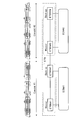
- FIG. 1 is a diagram showing an example of a connection relationship between ECN, ETB, and ETBN constituting a vehicle transmission system, and also describes a correspondence relationship with train organization.
- ECN # 1 is formed in the fixed composition # 1 (Consist # 1)
- ECN # 2 is formed in the fixed composition # 2 (Consist # 2).
- ECNs # 1 and # 2 are connected to the ETB formed over the fixed formations # 1 and # 2.
- Fixed organization # 1 is provided with ETBN # 1 and ETBN # 2 that relay signals between ECN # 1 and ETB.
- ETBN # 3 and ETBN # 4 that relay signals between ECN # 2 and ETB are installed in fixed organization # 2. Of these ETBNs, ETBN # 1 and # 3 operate as master ETBNs, and the remaining ETBNs # 2 and # 4 operate as backup ETBNs.
- one of the ETBNs connected to the same ECN operates as a master and the rest operate as a backup, so that a plurality of (two in the configuration example of FIG. 1) ETBNs connected to the same ECN are logically connected.
- ECN # 1 and EC2 are connected to train-mounted equipment (for example, a central device of a train information management system, an air conditioner, a lighting device, a brake device, etc.) not shown. Train-mounted devices connected to the same ECN communicate via ECN. Train-mounted devices connected to different ECNs communicate via ECN and ETB. In the case of the configuration example shown in FIG.
- FIG. 2 is a diagram showing an operation example of the ETBN constituting the vehicle transmission system shown in FIG. FIG. 2 shows operations of ETBN # 1 and ETBN # 2 as an example.
- the ETBN # 1 which is a master (ETBN Master), transmits a life / death monitoring frame (VRRP Advertisement) to the ETBN # 2 which is a backup (ETBN Backup) at a constant period (second unit).
- ETBN # 1 for example, received a frame transmitted from ECN # 2 communication device # 2 to ECN # 1 communication device # 1 from ETBN # 3 (master) on ECN # 2 side via ETBN # 2. If so, relay to ECN # 1.
- ETBN # 1 when a frame addressed to communication device # 2 is received from communication device # 1, ETBN # 1 relays to ETBN # 3 via ETBN # 2.
- the ETBN # 2 during the backup operation determines whether the ETBN # 1 is alive (whether it is operating normally) by monitoring reception of the ECN # 1 alive monitoring frame. Specifically, if the life / death monitoring frame cannot be received for a certain time longer than the transmission period of the life / death monitoring frame, it is determined that ETBN # 1 has failed.
- ETBN # 2 does not perform relay processing (relay from ECN # 1 to ETB, relay from ETB to ECN # 1) between ECN # 1 and ETB during the backup operation. However, relay within ETB, that is, relay processing between ETBN # 1 and ETBN # 3 is performed.
- FIG. 3 is a diagram showing an example of a problem in the conventional vehicle transmission system.
- the port to which ECN # 1 is connected fails in ETBN # 2 during the backup operation ((1) failure occurs)
- the alive monitoring frame from ETBN # 1 is displayed. Cannot receive.
- ETBN # 2 starts operation as a master when a certain time has elapsed since the occurrence of the failure. That is, ETBN # 2 receives ECN # 2 communication device # 2 from ETBN # 3 and transmits the data transmitted to ECN # 1 communication device # 1 without relaying the received data to ETBN # 1. Transfer to # 1 ((2), (3)).
- the port to which ECN # 1 is connected is out of order, data is discarded there ((4)).
- the conventional vehicle transmission system has a problem that when the port connected to the ECN in the ETBN during the backup operation fails, the operation as the master starts.
- the ETBN in which a port to which an ECN is connected malfunctions as a master, there is a problem that devices connected to different ECNs cannot communicate with each other.
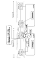
- FIG. 4 is a diagram illustrating a configuration example of a train information management apparatus to which the vehicle transmission system according to the present invention is applied.
- the train information management apparatus shown in the figure is composed of various devices mounted on each vehicle of a train in which a fixed train # 1 composed of vehicles 10A 1 to 10A m and a fixed train # 2 composed of vehicles 10B 1 to 10B n are connected. ing.
- Each vehicle is equipped with a terminal device 12 and a plurality of train-mounted devices 13 (hereinafter referred to as devices 13), and each fixed train head vehicle (vehicles 10A 1 , 10A m , 10B 1 and 10B n )
- a central device 11 is mounted.
- the device 13 is, for example, an air conditioner, a lighting device, a display device, a brake device, or the like.
- the ETBN 20 (ETBN 20A, 20B), which is a communication device according to the present invention. Is further installed.
- the ETBN 20 forms a backbone network (ETB) that connects ECN # 1 and ECN # 2.
- EDB backbone network
- Each fixed organization ETBN 20 is duplicated, one operating as a master and the other as a backup.
- the duplicated ETBN 20 may be mounted on a vehicle different from the illustrated vehicle. Two ETBNs may be mounted on different vehicles.
- the mounting position is not specified.
- the ETBN is duplicated
- a configuration in which the ETBN is further made redundant may be used.
- the duplexed ETBN 20 and the central device 11 are configured separately, but they may be integrated.
- the central device 11 is connected to a control operation device such as a master controller (mascon) (not shown), and performs input / output processing of train information such as train identification information, train position information, train operation information, and train command information.
- a control operation device such as a master controller (mascon) (not shown)
- train information such as train identification information, train position information, train operation information, and train command information.
- the terminal device 12 transmits data including control information output from each central device 11 to each device 13, collects data output from each device 13, and transmits the data to each central device 11. .
- the terminal device 12 collects and shares train information in cooperation with each other.
- the data output from each device 13 includes information indicating a transmission destination (central device 11) of the data, a device ID for identifying the transmission source device, and operation state information of the device 13 (for example, air conditioning Since the current temperature, VVVF output, and the like are included, the central device 11 that has received data from each device 13 can identify which device is the operating state information transmitted.
- the ETBN 20 When operating as a master, the ETBN 20 relays the signal received from the ECN to the ETB and relays the signal received from the ETB to the ECN. In addition, a life / death monitoring frame (VRRP Advertisement) is periodically transmitted to the ETBN 20 during backup operation via ECN.
- a life / death monitoring frame (VRRP Advertisement) is periodically transmitted to the ETBN 20 during backup operation via ECN.
- failure detection of the ETBN 20 operating as the master is performed based on the reception result of the life / death monitoring frame transmitted from the ETBN 20 operating as the master. Note that it may be detected whether the fixed knitting is connected or not, and the ETBN 20 may operate as a master or a backup only in a state where the fixed knitting is connected. As a result, it is possible to prevent the life and death monitoring frame from being transmitted unnecessarily and prevent the traffic in the ECN from increasing, and the power consumption of the ETBN 20 can be reduced.
- the central device 11 outputs data (hereinafter referred to as “control command”) including device individual data (control data) for controlling the operation of each device 13 to each terminal device 12.
- control command data
- the terminal device 12 that has received the control command transfers the control command to the device 13 connected to the own terminal device 12, and each device 13 that has received the control command performs an operation according to the device individual data included in the control command. Execute.
- data from each device 13 including the operation state information is collected by each terminal device 12 and transmitted to the central device 11.
- the central device 11 that has received the data from each device 13 records the data and outputs operating state information to a display (not shown) installed in the cab or the like. Displays information necessary for train operation.
- FIG. 5 is a diagram illustrating a configuration example of the ETBN 20.
- the ETBN 20 includes a relay unit 30 that relays a signal between the ECN and the ETB, and an operation mode determination unit 40 that determines whether the own ETBN operates as a master or a backup ETBN.
- the operation mode determination unit 40 includes an ECN port identification unit 41, an IP address management unit 42, a VRRP function unit 43, a port failure detection unit 44, and a life / death determination unit 45.
- the relay unit 30 receives a frame from the ECN, and the received frame becomes a VRRP frame (a frame having a format defined by VRRP, hereinafter referred to as “ This is referred to as a “VRRP frame”. If it is a VRRP frame, it is relayed to the VRRP function unit 43 of the operation mode determination unit 40, and if it is not a VRRP frame, it is converted into a format corresponding to the ETB and relayed to the ETB. When a frame is received from the ETB, it is converted into a format corresponding to ECN and relayed to ECN.
- a VRRP frame a frame having a format defined by VRRP, hereinafter referred to as “ This is referred to as a “VRRP frame”. If it is a VRRP frame, it is relayed to the VRRP function unit 43 of the operation mode determination unit 40, and if it is not a VRRP frame, it is converted into a format corresponding to the ETB and relayed to the ETB.
- a life / death monitoring frame (VRRP Advertisement, a kind of VRRP frame) periodically generated by the VRRP function unit 43 is received and transmitted to the ECN.
- the relay unit 30 checks whether the received frame is a VRRP frame, and if it is a VRRP frame, It relays to the VRRP function part 43 of the operation mode determination part 40, and when it is not a VRRP frame, it discards (it does not relay to ETB).
- the frame addressed to another ETBN is received from the ETB, the frame is forwarded toward the other ETBN.
- the operation mode determination unit 40 determines whether the own ETBN operates as a master or a backup, and notifies the relay unit 30 of the determination result. Moreover, the operation
- the ECN port identification unit 41 is connected to an ECN from a plurality of physical ports based on a correspondence table of physical ports and IP addresses managed by the IP address management unit 42. An ECN port that is a physical port is specified.
- the IP address management unit 42 manages information on IP addresses (physical port and IP address correspondence table) assigned to each physical port included in the own ETBN.
- the VRRP function unit 43 that operates as a life and death monitoring frame processing unit performs control based on VRRP (Virtual Router Redundancy Protocol) with another ETBN that logically behaves as one ETBN.
- VRRP Virtual Router Redundancy Protocol
- the port failure detection unit 44 detects failure of the ECN port. There are no specific rules for failure detection.
- the life / death determination unit 45 determines whether or not the ETBN operating as the master is operating normally while the own ETBN is operating as the backup.
- ETBN20 1 shown in FIG. 6 is a master
- ETBN20 2 operates as a backup, logically assumed that behaves as a single ETBN.
- FIG. 6 shows only components necessary for executing the characteristic operation (corresponding to the components of the operation mode determination unit 40 shown in FIG. 5).
- ETBN20 1 of ECN port identifying unit 41 1 the self-device (ETBN20 1) is started, is managed by the IP address management unit 42 1, referring to the correspondence table of the physical port and IP address, ECN is connected
- a physical port (hereinafter referred to as “ECN port”) is specified.
- Non-Patent Document 1 stipulates that the range of IP addresses assigned to devices that communicate with ECN is 10.128.64.0/18 to 10.143.0.0/18. For this reason, the ECN port specifying unit 41 1 determines that a physical port to which an IP address within the above range is assigned is an ECN port.
- the ECN port identification unit 41 1 notifies the VRRP function unit 43 1 and the port failure detection unit 44 1 of the identification result (physical port corresponding to the ECN port).
- the ECN port specifying unit 41 2 of the ETBN 20 2 specifies the ECN port when the own apparatus (ETBN 20 2 ) is activated. Further, the specific result is notified to the VRRP function unit 43 2 and the port failure detection unit 44 2 .
- ETBN20 1 of VRRP function unit 43 1 the specific process of ECN port by ECN port identification unit 41 1 is completed, the decision to operate as the master executes a predetermined procedure according to VRRP.
- VRRP function unit 43 2 of ETBN20 2 when the identification processing of ECN port by ECN port identification unit 41 2 is completed, is determined to act as a backup by executing a predetermined procedure according to VRRP.
- VRRP function unit 43 life-and-death monitoring frame (VRRP Advertisement) periodically generates and sends to the ECN port through the relay unit (not shown).
- VRRP Advertisement life-and-death monitoring frame
- VRRP function unit 43 2 receives the life-and-death monitoring frame transmitted from the VRRP function unit 43 1 of the master side. Each time the VRRP function unit 43 2 receives the alive monitoring frame, it notifies the alive determination unit 45 2 to that effect.
- the port failure detection unit 44 2 monitors whether the ECN port specified by the ECN port specifying unit 41 2 has failed.
- the life / death determination unit 45 2 detects a failure of the ETBN master (ETBN 20 1 operating as a master) based on the reception result of the life / death monitoring frame in the VRRP function unit 43 2 and the monitoring result in the port failure detection unit 44 2 . . Specifically, when the ECN port is in a normal state and the life / death monitoring frame cannot be received for a predetermined time (not transmitted from the ETBN master), it is determined that the ETBN master has failed (see FIG. 7). If the ECN port is faulty, it is assumed that the ETBN master is operating normally. When the life / death determination unit 45 2 detects a failure of the ETBN master, the life / death determination unit 45 2 notifies the VRRP function unit 43 2 to that effect. Note that the above-mentioned fixed time is defined as Master_Down_Interval in VRRP.
- the VRRP function unit 43 2 determines that the own device (ETBN 20 2 ) starts the operation as the master. Then, the relay unit (not shown) is instructed to start an operation as a master (that is, start an operation of relaying a signal between ECN and ETB) and itself (the VRRP function unit 43 2). ) Also starts an operation as a master (an operation for periodically generating and transmitting a life / death monitoring frame).
- the redundant ETBN of the vehicle transmission system operates as a backup
- the reception status of the alive monitoring frame transmitted from the master via the ECN, and the status of the ECN port ( Whether or not there is a failure) is monitored, and when the life / death monitoring frame cannot be received in a state where the ECN port has not failed, it is determined that the master ETBN has failed, and the operation is started as the master ETBN.
- the possibility that the ETBN operating as the backup erroneously detects the failure of the ETBN operating as the master can be reduced. Further, it is possible to solve the problem that when the ECN port fails, the operation as a master is started, and devices connected to different ECNs cannot communicate with each other.
- VRRP is used to realize redundancy of communication devices.
- the active system master
- the active system periodically transmits frames for alive monitoring and uses the frames.
- the present invention can be applied to any system in which the standby system (backup) realizes redundancy by detecting the failure of the active system.
- the communication device is useful for a vehicle transmission system, and in particular, relays a signal between branch networks formed in a fixed train in a train in which a plurality of fixed trains are connected. Suitable for communication devices.
Landscapes
- Engineering & Computer Science (AREA)
- Computer Networks & Wireless Communication (AREA)
- Signal Processing (AREA)
- Health & Medical Sciences (AREA)
- General Health & Medical Sciences (AREA)
- Cardiology (AREA)
- Environmental & Geological Engineering (AREA)
- Computer Security & Cryptography (AREA)
- Small-Scale Networks (AREA)
- Data Exchanges In Wide-Area Networks (AREA)
- Computing Systems (AREA)
- Medical Informatics (AREA)
Abstract
Description
本実施の形態では、異なる固定編成内にそれぞれ形成されている支線ネットワーク(ECN)の間で信号を中継する通信装置(ETBN)が冗長化された車両伝送システムにおける前記通信装置について説明する。
Claims (4)
- 固定編成が連結された状態の列車において、固定編成内に形成された支線ネットワークの間で信号を中継する基幹ネットワークを冗長化された他の通信装置とともに形成する通信装置であって、
マスターとして動作中は死活監視フレームを支線ネットワーク経由でバックアップとして動作中の他の通信装置へ周期的に送信し、バックアップとして動作中はマスターとして動作中の他の通信装置から送信された死活監視フレームを支線ネットワーク経由で受信する死活監視フレーム処理部と、
支線ネットワークが接続されているポートの故障検知を行うポート故障検知部と、
バックアップとして動作中に、前記死活監視フレーム処理部での死活監視フレーム受信結果および前記ポート故障検知部での故障検知結果に基づいて、マスターとして動作中の他の通信装置の故障検知を行う死活判定部と、
を備えることを特徴とする通信装置。 - 前記死活判定部は、前記ポート故障検知部が故障を検知していない状態において前記死活監視フレーム処理部が死活監視フレームを一定時間にわたって受信しない場合に故障と判断することを特徴とする請求項1に記載の通信装置。
- マスターとして動作中にはIEC61375 2-5で規定されたETBNとして動作することを特徴とする請求項1に記載の通信装置。
- 固定編成が連結された状態の列車において、固定編成内に形成された支線ネットワークおよび支線ネットワークの間で信号を中継する基幹ネットワークを含み、基幹ネットワークを形成する通信装置が冗長化された構成の車両伝送システムであって、
前記通信装置が、
マスターとして動作中は死活監視フレームを支線ネットワーク経由でバックアップとして動作中の他の通信装置へ周期的に送信し、バックアップとして動作中はマスターとして動作中の他の通信装置から送信された死活監視フレームを支線ネットワーク経由で受信する死活監視フレーム処理部と、
支線ネットワークが接続されているポートの故障検知を行うポート故障検知部と、
バックアップとして動作中に、前記死活監視フレーム処理部での死活監視フレーム受信結果および前記ポート故障検知部での故障検知結果に基づいて、マスターとして動作中の他の通信装置の故障検知を行う死活判定部と、
を備えることを特徴とする車両伝送システム。
Priority Applications (5)
| Application Number | Priority Date | Filing Date | Title |
|---|---|---|---|
| US14/764,384 US10069709B2 (en) | 2013-05-17 | 2013-05-17 | Communication apparatus and vehicle transmission system |
| PCT/JP2013/063801 WO2014184952A1 (ja) | 2013-05-17 | 2013-05-17 | 通信装置および車両伝送システム |
| JP2015515056A JP5836539B2 (ja) | 2013-05-17 | 2013-05-17 | 通信装置および車両伝送システム |
| EP13884764.5A EP2999164B1 (en) | 2013-05-17 | 2013-05-17 | System and vehicle for detecting malfunctioning communication apparatus |
| TW102133128A TW201444717A (zh) | 2013-05-17 | 2013-09-13 | 通信裝置及車輛傳送系統 |
Applications Claiming Priority (1)
| Application Number | Priority Date | Filing Date | Title |
|---|---|---|---|
| PCT/JP2013/063801 WO2014184952A1 (ja) | 2013-05-17 | 2013-05-17 | 通信装置および車両伝送システム |
Publications (1)
| Publication Number | Publication Date |
|---|---|
| WO2014184952A1 true WO2014184952A1 (ja) | 2014-11-20 |
Family
ID=51897957
Family Applications (1)
| Application Number | Title | Priority Date | Filing Date |
|---|---|---|---|
| PCT/JP2013/063801 Ceased WO2014184952A1 (ja) | 2013-05-17 | 2013-05-17 | 通信装置および車両伝送システム |
Country Status (5)
| Country | Link |
|---|---|
| US (1) | US10069709B2 (ja) |
| EP (1) | EP2999164B1 (ja) |
| JP (1) | JP5836539B2 (ja) |
| TW (1) | TW201444717A (ja) |
| WO (1) | WO2014184952A1 (ja) |
Cited By (3)
| Publication number | Priority date | Publication date | Assignee | Title |
|---|---|---|---|---|
| CN105262855A (zh) * | 2015-10-21 | 2016-01-20 | 北京锦鸿希电信息技术股份有限公司 | 基于列车的ip地址分配方法和列车通信网络 |
| EP3179674A1 (en) * | 2015-12-10 | 2017-06-14 | KNORR-BREMSE Systeme für Schienenfahrzeuge GmbH | Configurable gateway apparatus and method for an integrated brake control system in a railway vehicle |
| CN111891181A (zh) * | 2020-06-23 | 2020-11-06 | 株洲中车时代电气股份有限公司 | 基于以太网的列车网络控制系统 |
Families Citing this family (9)
| Publication number | Priority date | Publication date | Assignee | Title |
|---|---|---|---|---|
| US9787542B2 (en) * | 2013-05-20 | 2017-10-10 | Mitsubishi Electric Corporation | Train-information management device and train-information management method |
| CN106143532B (zh) * | 2015-04-08 | 2018-01-09 | 中车大连电力牵引研发中心有限公司 | 列车动态重联的方法及节点 |
| CN108092854B (zh) * | 2017-12-29 | 2023-04-28 | 中国铁路总公司 | 基于iec61375协议的列车级以太网设备的测试方法及装置 |
| CN110958167B (zh) * | 2019-12-06 | 2022-09-09 | 中车大连电力牵引研发中心有限公司 | 一种高速智能网络控制系统 |
| CN112693504B (zh) * | 2021-03-25 | 2021-06-22 | 北京全路通信信号研究设计院集团有限公司 | 一种基于车车通信的多列车控制系统及方法 |
| CN113839988B (zh) * | 2021-08-24 | 2024-02-20 | 四川发展磁浮科技有限公司 | 一种列车多网融合网络控制系统和控制方法 |
| CN113810297B (zh) * | 2021-09-15 | 2023-04-18 | 中国铁道科学研究院集团有限公司 | 一种多网融合列车网络系统及其通信方法 |
| CN116112313B (zh) * | 2021-11-11 | 2025-03-18 | 株洲中车时代电气股份有限公司 | 牵引控制系统和轨道交通系统 |
| CN116424400B (zh) * | 2022-01-04 | 2025-09-16 | 中车株洲电力机车研究所有限公司 | 列车初运行控制方法、装置、网络设备及列车系统 |
Citations (3)
| Publication number | Priority date | Publication date | Assignee | Title |
|---|---|---|---|---|
| JP2007312091A (ja) | 2006-05-18 | 2007-11-29 | Central Res Inst Of Electric Power Ind | ルーチング装置および障害復旧方法 |
| JP2011055416A (ja) * | 2009-09-04 | 2011-03-17 | Mitsubishi Electric Corp | 列車内伝送制御システム |
| JP2013085085A (ja) * | 2011-10-07 | 2013-05-09 | Maspro Denkoh Corp | 無線通信装置 |
Family Cites Families (11)
| Publication number | Priority date | Publication date | Assignee | Title |
|---|---|---|---|---|
| CA2290267A1 (en) * | 1998-12-04 | 2000-06-04 | Nortel Networks Corporation | Method and apparatus providing for an improved virtual routing redundancy protocol |
| JP3824906B2 (ja) | 2001-10-30 | 2006-09-20 | 古河電気工業株式会社 | ネットワーク間接続方法、その装置およびその装置を用いたネットワーク間接続システム |
| JP3896897B2 (ja) | 2002-05-24 | 2007-03-22 | 株式会社日立製作所 | ルータ設定方法およびルータ |
| CN1208929C (zh) | 2002-06-23 | 2005-06-29 | 华为技术有限公司 | 一种利用虚拟路由器冗余协议实现路由器接口备份的方法 |
| JP2005130049A (ja) | 2003-10-21 | 2005-05-19 | Fujitsu Ltd | ノード |
| WO2006035575A1 (ja) | 2004-09-28 | 2006-04-06 | Nec Corporation | 冗長化パケット交換システムおよび冗長化パケット交換システムの系切り替え方法 |
| US20070061056A1 (en) * | 2005-09-14 | 2007-03-15 | Bombardier Transportation Gmbh | Bypass switch for an ethernet-type network |
| JP2008015722A (ja) * | 2006-07-05 | 2008-01-24 | Hitachi Electronics Service Co Ltd | データ処理システム |
| US7573812B2 (en) * | 2006-12-21 | 2009-08-11 | Telefonaktiebolaget L M Ericsson (Publ) | Passive virtual router redundancy prototcol |
| GB2450520A (en) * | 2007-06-27 | 2008-12-31 | Bombardier Transp Gmbh | Communication system transferring information within a railway train |
| US9680948B2 (en) * | 2013-03-14 | 2017-06-13 | Arista Networks, Inc. | System and method for device failure notification |
-
2013
- 2013-05-17 WO PCT/JP2013/063801 patent/WO2014184952A1/ja not_active Ceased
- 2013-05-17 JP JP2015515056A patent/JP5836539B2/ja active Active
- 2013-05-17 EP EP13884764.5A patent/EP2999164B1/en active Active
- 2013-05-17 US US14/764,384 patent/US10069709B2/en active Active
- 2013-09-13 TW TW102133128A patent/TW201444717A/zh unknown
Patent Citations (3)
| Publication number | Priority date | Publication date | Assignee | Title |
|---|---|---|---|---|
| JP2007312091A (ja) | 2006-05-18 | 2007-11-29 | Central Res Inst Of Electric Power Ind | ルーチング装置および障害復旧方法 |
| JP2011055416A (ja) * | 2009-09-04 | 2011-03-17 | Mitsubishi Electric Corp | 列車内伝送制御システム |
| JP2013085085A (ja) * | 2011-10-07 | 2013-05-09 | Maspro Denkoh Corp | 無線通信装置 |
Non-Patent Citations (1)
| Title |
|---|
| See also references of EP2999164A4 |
Cited By (4)
| Publication number | Priority date | Publication date | Assignee | Title |
|---|---|---|---|---|
| CN105262855A (zh) * | 2015-10-21 | 2016-01-20 | 北京锦鸿希电信息技术股份有限公司 | 基于列车的ip地址分配方法和列车通信网络 |
| CN105262855B (zh) * | 2015-10-21 | 2018-10-02 | 北京锦鸿希电信息技术股份有限公司 | 基于列车的ip地址分配方法和列车通信网络 |
| EP3179674A1 (en) * | 2015-12-10 | 2017-06-14 | KNORR-BREMSE Systeme für Schienenfahrzeuge GmbH | Configurable gateway apparatus and method for an integrated brake control system in a railway vehicle |
| CN111891181A (zh) * | 2020-06-23 | 2020-11-06 | 株洲中车时代电气股份有限公司 | 基于以太网的列车网络控制系统 |
Also Published As
| Publication number | Publication date |
|---|---|
| EP2999164A1 (en) | 2016-03-23 |
| US20150381458A1 (en) | 2015-12-31 |
| EP2999164B1 (en) | 2021-03-24 |
| JPWO2014184952A1 (ja) | 2017-02-23 |
| TW201444717A (zh) | 2014-12-01 |
| EP2999164A4 (en) | 2016-12-28 |
| US10069709B2 (en) | 2018-09-04 |
| JP5836539B2 (ja) | 2015-12-24 |
Similar Documents
| Publication | Publication Date | Title |
|---|---|---|
| JP5836539B2 (ja) | 通信装置および車両伝送システム | |
| US10708132B2 (en) | Technique for handling a status change in an interconnect node | |
| US7940645B2 (en) | Protection switching method based on change in link status in ethernet link aggregation sublayer | |
| CN203747852U (zh) | 用于可冗余操作的工业通信网络的通信设备 | |
| US20070061056A1 (en) | Bypass switch for an ethernet-type network | |
| TWI674488B (zh) | 控制系統、及中繼裝置 | |
| US11171808B2 (en) | Switch device, communication control method, and recording medium | |
| CN104309598A (zh) | 一种机车制动机控制方法和系统 | |
| US20120039165A1 (en) | Network Interface | |
| CN102377600B (zh) | 对数据传输网络的网络元件的保护 | |
| US8959386B2 (en) | Network and expansion unit and method for operating a network | |
| CN105637811A (zh) | 语义消重 | |
| JP4340731B2 (ja) | ネットワークの障害監視処理システム及び方法 | |
| JP6359914B2 (ja) | 中継システムおよび中継装置 | |
| JP5349717B1 (ja) | 列車情報管理装置 | |
| JP4472535B2 (ja) | 情報伝送システム、鉄道車両用情報伝送システム及び車両用情報伝送端末装置 | |
| JP2003008581A (ja) | 通信制御装置 | |
| JP4258016B2 (ja) | ネットワーク構成制御システム | |
| JP5651878B2 (ja) | 障害監視システム | |
| JP5718287B2 (ja) | ネットワーク障害監視システムおよび方法 | |
| JP6081017B2 (ja) | 列車情報管理装置 | |
| JP5317197B2 (ja) | 他の通信装置との接続確認を行う方法及び通信システム | |
| JP2009159080A (ja) | 遠隔監視制御システム | |
| KR20130093845A (ko) | 네트워크 장치 및 그것의 링크 관리 방법 | |
| JP2012235477A (ja) | ネットワーク管理装置、ネットワーク管理システム及び通信機器 |
Legal Events
| Date | Code | Title | Description |
|---|---|---|---|
| 121 | Ep: the epo has been informed by wipo that ep was designated in this application |
Ref document number: 13884764 Country of ref document: EP Kind code of ref document: A1 |
|
| ENP | Entry into the national phase |
Ref document number: 2015515056 Country of ref document: JP Kind code of ref document: A |
|
| WWE | Wipo information: entry into national phase |
Ref document number: 14764384 Country of ref document: US |
|
| WWE | Wipo information: entry into national phase |
Ref document number: 2013884764 Country of ref document: EP |
|
| NENP | Non-entry into the national phase |
Ref country code: DE |