WO2014185154A1 - Structure de partie supérieure d'une carrosserie de véhicule - Google Patents
Structure de partie supérieure d'une carrosserie de véhicule Download PDFInfo
- Publication number
- WO2014185154A1 WO2014185154A1 PCT/JP2014/058330 JP2014058330W WO2014185154A1 WO 2014185154 A1 WO2014185154 A1 WO 2014185154A1 JP 2014058330 W JP2014058330 W JP 2014058330W WO 2014185154 A1 WO2014185154 A1 WO 2014185154A1
- Authority
- WO
- WIPO (PCT)
- Prior art keywords
- rail
- stiffener
- wall
- pillar
- bulkhead
- Prior art date
- Legal status (The legal status is an assumption and is not a legal conclusion. Google has not performed a legal analysis and makes no representation as to the accuracy of the status listed.)
- Ceased
Links
Images


Classifications
-
- B—PERFORMING OPERATIONS; TRANSPORTING
- B62—LAND VEHICLES FOR TRAVELLING OTHERWISE THAN ON RAILS
- B62D—MOTOR VEHICLES; TRAILERS
- B62D25/00—Superstructure or monocoque structure sub-units; Parts or details thereof not otherwise provided for
- B62D25/06—Fixed roofs
-
- B—PERFORMING OPERATIONS; TRANSPORTING
- B62—LAND VEHICLES FOR TRAVELLING OTHERWISE THAN ON RAILS
- B62D—MOTOR VEHICLES; TRAILERS
- B62D25/00—Superstructure or monocoque structure sub-units; Parts or details thereof not otherwise provided for
- B62D25/04—Door pillars ; windshield pillars
-
- B—PERFORMING OPERATIONS; TRANSPORTING
- B62—LAND VEHICLES FOR TRAVELLING OTHERWISE THAN ON RAILS
- B62D—MOTOR VEHICLES; TRAILERS
- B62D27/00—Connections between superstructure or understructure sub-units
- B62D27/02—Connections between superstructure or understructure sub-units rigid
Definitions
- the present invention relates to an upper body structure of a car or the like.
- a roof panel, a plurality of roof rails extending in the vehicle width direction on the lower surface of the roof panel to hold the roof panel, and both end portions of the roof rail are combined in a vehicle body upper portion of an automobile and extended in the vehicle longitudinal direction.
- a roof side rail is provided, and a pillar whose upper end is joined to the roof side rail and extends downward is provided.
- the roof structure of the vehicle body disclosed by patent document 1 is known, for example.
- an outer panel forming a groove by a roof panel in a longitudinal sectional view, an inner panel joined to the inner side of the outer panel to form a closed cross section, and a closed cross section between the outer panel and the inner panel
- the roof side rail is welded by welding stiffeners (stiffeners) and reinforcing members (bulkheads) joined to the inner side of stiffeners with a substantially U-shaped (substantially U-shaped) cross section to form a closed cross section. Improves the rigidity of the roof rail joint.
- the reinforcing member is disposed below the groove formed in the roof panel through an opening formed between the substantially U-shaped (substantially U-shaped) cross section of the extending piece and the lower surface of the stiffener.
- the reinforcing member has one end welded to the extension piece and the bulkhead at the other end welded to the inner lower surface of the inner panel.
- this invention was invented in order to eliminate the said problem, and it makes it a subject to provide the vehicle body upper structure which improved the rigidity and strength of a roof side rail.
- a vehicle body upper structure comprises a rail inner, a rail outer joined to the vehicle outer side of the rail inner to form a closed cross section, and between the rail inner and the rail outer
- a vehicle body upper structure including a roof side rail extending in the front-rear direction above the vehicle body side portion, and a pillar depending from the roof side rail.
- the vehicle body upper structure joins the bulkhead to the rail stiffener at the intersection of the pillar and the roof side rail, and is bolted to the rail inner, so that the prior art of the patent document 1 Without providing such an opening, the bulkhead can be joined to both the rail stiffener on the outside of the vehicle in the vehicle width direction and the rail inner on the inside of the vehicle. Furthermore, since the bulkhead is installed to divide the closed cross section between the rail inner and the rail stiffener, the rigidity and strength of the intersection of the pillar and the roof side rail can be improved. In addition, since the rail outer is joined to the rail inner and not bolted, the outer shape is not restricted, and the design of the rail outer can be improved.
- the bulkhead includes an inner wall fastened to the rail inner, a front wall extending from the front end of the inner wall to the vehicle outer side, and a rear wall extending from the rear end of the inner wall to the vehicle outer side
- a hat-shaped cross section is formed by a first front flange extending forward from the front wall and a first rear flange extending rearward from the rear wall.
- the bulkhead formed in the hat-shaped cross section is disposed on the roof side by arranging the front wall and the rear wall to extend in the vehicle width direction between the rail inner and the rail stiffener.
- the rigidity and strength of the rail can be improved.
- the rail stiffener includes a stiffener upper wall formed at the upper portion of the rail stiffener, a stiffener hanging lower wall downwardly depending from an outer end in the vehicle width direction of the stiffener upper wall, and a lower end of the stiffener hanging lower wall.
- the stiffener lower wall extending to the center side in the vehicle width direction is formed in a U-shaped cross section (substantially U-shaped), and the bulkhead extends forward from the lower end of the front wall to lower the stiffener
- a flange is joined to the stiffener hanging wall.
- the bulkhead includes the second front flange joined to the stiffener lower wall and the second rear flange joined to the stiffener lower wall, and the first front flange and the first rear flange are stiffened. It is joined to the hanging wall.
- the rail inner and the bulkhead should perform not only so-called B-plane coupling (coupling of planes orthogonal to the vehicle body lateral direction axis) but also H-plane coupling (coupling of planes orthogonal to the vehicle body vertical direction axis). Rigidity and strength can be improved.
- the rail stiffener has a notch in the upper wall of the stiffener at a position corresponding to the second front flange and the second rear flange, in which a spot gun can be inserted.
- the rail stiffener is provided with the roof side rail inner and the bulkhead by forming the notch portion through which the spot gun can be inserted at the portion corresponding to the second front flange and the second rear flange. Not only B-face bonding but also H-face bonding can be performed.
- the bulkhead is connected to the bulk upper wall extending from the upper end of the inner side wall to the vehicle outer side in the vehicle width direction and extending rearward from the upper end of the front wall and joined to the bulk upper wall It is preferable to have a front flange and a third rear flange that extends forward from the upper end of the rear wall and is joined to the bulk upper wall.
- the bulkhead extends forward from the upper end of the rear wall, a third front flange that extends rearward from the upper end of the front wall and is joined to the upper wall, and extends from the upper end of the rear wall.
- the rail inner is divided into a front rail inner member and a rear rail inner member back and forth, and a divided joint portion where the rear end of the front rail inner member and the front end of the rear rail inner member are joined It is preferable that the split joint be disposed at a position overlapping the bulkhead in the vehicle width direction.
- the rail inner is improved by increasing the rigidity and strength of the split joint by arranging the split joint where the front rail inner member and the rear rail inner member are joined to be wrapped with the bulkhead. Can.
- the inner side wall of the bulkhead is provided with a concave portion which is concave toward the vehicle outer side in the vehicle width direction at a position overlapping the divided joint portion in the vehicle width direction.
- the bulkhead has a step shape because the front rail inner member and the rear rail inner member are installed in two layers at the position where the junction divisions and the bulkhead overlap.
- the bulkhead can absorb the swelling of the step-shaped portion by having a recessed portion that is recessed toward the vehicle outer side in the vehicle width direction. For this reason, in the portion where the front rail inner member and the rear rail inner member are overlapped, the rail inner does not bulge inward in the vehicle width, and the influence on the joint with the pillar inner can be eliminated.
- the pillar includes a pillar inner whose upper end is attached to an inner side surface of the rail inner, and the pillar inner, the rail inner and the bulkhead are fastened together by a bolt.
- the pillar can improve the rigidity and strength of the intersection between the pillar and the roof side rail by bolting the pillar inner, the rail inner and the bulkhead together.
- the pillar includes a pillar stiffener whose upper end is attached to the outer surface of the rail stiffener, and the bulkhead includes a spot gun insertion hole for spot coupling the rail stiffener and the pillar stiffener. Is preferred.
- the intersection of the pillar and the roof side rail Because the bulkhead is disposed, the bulkhead interferes with the bonding of the rail stiffener and the pillar stiffener.
- the rail stiffener and the pillar stiffener can be joined by forming the spot gun insertion hole in the bulkhead. Therefore, the workability of the assembling operation can be improved, and the bulkhead is disposed at the intersection of the pillar and the roof side rail, so that the rigidity and strength of the intersection can be improved.
- the rigidity and strength of the roof rail can be further improved.
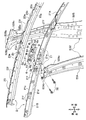
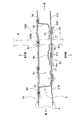
- FIG. 8 It is a principal part schematic side view of the vehicle body which shows an example of the vehicle body upper structure which concerns on embodiment of this invention. It is an expansion perspective view of the I section of FIG. It is a principal part disassembled perspective view which shows the assembly state of a bulkhead. It is a principal part disassembled perspective view which shows the fastening state of a bulkhead and a rail inner. It is a perspective view to a bulkhead. It is a principal part enlarged plan view of a rail stiffener provided with a bulkhead. It is a principal part expansion perspective view of a rail inner provided in a rail stiffener. It is II-II sectional drawing of FIG. FIG. 8 is a cross-sectional view taken along the line III-III in FIG.
- FIGS. 1 to 9 A vehicle body upper structure according to an embodiment of the present invention will be described with reference to FIGS. 1 to 9.
- “front” is the forward side of the vehicle C
- “rear” is the backward side of the vehicle C
- “upper” is the vertically upper side
- “lower” is the vertically lower side.
- a vehicle C in which the vehicle body upper structure according to the present invention is adopted will be described.
- the vehicle C is extended downward from the roof side rail 2 installed at the left and right ends of the roof rail 12 extended in the vehicle width direction, and the roof side rail 2.
- the type and shape of the vehicle C are not particularly limited. That is, as long as the vehicle C includes the roof side rail 2 and the pillars 5 in the vehicle body 1, it may be a passenger car, a bus, a truck, a working vehicle or the like.
- the vehicle C includes the roof side rail 2 and the pillars 5 in the vehicle body 1, it may be a passenger car, a bus, a truck, a working vehicle or the like.
- the vehicle body 1 is a frame member for forming the whole of the vehicle C, and for example, various metal vehicle frames such as a roof side rail 2 described later and a roof panel 11 (see FIG. 8) Etc.) and the like.
- a door opening 1 b for the front seat and a door opening 1 c for the rear seat are formed in the vehicle body side portions 1 a on both sides of the vehicle body 1.
- the vehicle body side part 1a is formed in substantially left-right symmetry, the vehicle body 1 mainly demonstrates a front passenger seat (left side), and abbreviate
- the vehicle body upper portion 1 d is an upper portion of the entire vehicle body 1, and includes a roof panel 11 (see FIG. 8) constituting a roof portion of the vehicle body 1 and a frame near the left and right sides thereof Mainly composed of
- the roof portion of the vehicle body 1 includes the roof panel 11, the roof rail 12 installed below the roof panel 11, and roof side rails provided at both ends in the vehicle width direction of the roof rail 12 and extending in the front-rear direction 2 and a pillar 5 extending downward from the roof rail 12.
- the pillar 5 is configured to include, for example, a front pillar 51, a center pillar 52, a quarter pillar 53, and a rear pillar 54.
- the front pillars 51 are pillars provided on the left and right of a windshield (not shown).
- the center pillar 52 is a pillar provided between the door opening 1 b and the door opening 1 c.
- the quarter pillar 53 is a pillar provided on the rear side of the door opening 1 c.
- the rear pillar 54 is a pillar provided from the top of the luggage compartment R2 toward the rear end of the vehicle body 1.
- the roof panel 11 is a plate member that forms the roof of the vehicle body 1, and is made of a metal plate such as a rolled steel plate formed in a substantially rectangular shape in plan view.
- the left and right end portions of the roof panel 11 form a half of a groove portion 1 e which is formed in a concave shape in a front view.
- the roof panel 11 is connected and fixed by spot welding by overlapping the rail outer 22 of the roof side rail 2, the roof rail 12, and the rail inner 21 of the roof side rail 2 at the bottom surface portion of the groove portion 1e.
- X marks in FIG. 4 to FIG. 6 indicate welding points.
- the roof rail 12 is a member for supporting the roof panel 11 (see FIG. 8) from the lower side, and is bridged between the left and right roof side rails 2, 2.
- a plurality of the roof rails 12 are provided at appropriate intervals from the front end to the rear end of the roof side rail 2.
- the left and right end portions of the roof rail 12 are held by a rail inner 21 and a rail outer 22 (see FIG. 8) described later.
- the roof side rail 2 is a frame member extending in the front-rear direction above the vehicle body side portion 1 a, and the roof side rail 2 is joined at its upper end portion to hang downward.
- a plurality of pillars 5 are provided.
- the roof side rail 2 is a member extending in the longitudinal direction of the vehicle body, and forms the door openings 1b and 1c and the upper edge of the luggage room R2.
- the roof side rail 2 at the site where the center pillar 52 (also referred to as "B-pillar") disposed on the vehicle body side portion 1a of the vehicle body upper portion 1d at the central portion on the left side of the vehicle C An example will be described.
- the roof side rail 2 includes a rail inner 21 on the inner side of the vehicle and a rail outer 22 (see FIG. 8) joined to the outer side of the rail inner 21 to form a closed cross section 2a (see FIG. 8).
- a rail stiffener 23 sandwiched between the rail inner 21 and the rail outer 22 to divide the closed cross section 2a, a bulkhead 6 provided on the vehicle outer side of the rail inner 21 and a nut mounted on the vehicle outer side of the rail stiffener 23 31, a bolt 32 fastened to the nut 31, and a pillar 5 (center pillar 52).
- the rail inner 21 is a member extending perpendicularly to the vehicle outer side of the upper end portion of the pillar inner 52 ⁇ / b> A and extending in the front-rear direction.
- the rail inner 21 is a member for holding the roof panel 11 and the roof rail 12 as shown in FIG.
- the rail inner 21 is formed by joining together two members divided into front and rear into a front rail inner member 21A and a rear rail inner member 21B.
- the rail inner 21 has an inner side wall portion 21a vertically disposed on the inner side of the rail outer 22, a bolt insertion hole 21b formed in the inner side wall portion 21a, and an inner side wall portion 21a.
- Inner upper flap 21c bent substantially horizontally from the upper part of the inner side toward the vehicle inner side, an inner lower flap 21d bent obliquely downward from the lower part of the inner side wall 21a, and a front rail inner member 21A
- a split joint 21e is formed by joining the rear end of the rear rail inner member 21B to the front end of the rear rail inner member 21B, and the projection 21f engaged with the notches 23d to 23f formed in the rail stiffener 23.
- the inner upper flap 21 c at the upper end is joined to the outer upper flap 22 a and the stiffener upper wall 23 a, and the inner lower flap 21 d at the lower end is joined to the rail outer 22.
- the rail outer 22 and the longitudinal cross section form a closed cross section 2a.
- the rail inner 21 is a half that forms a tubular frame member together with the rail outer 22.
- the head of a bolt 32 inserted in the bolt insertion hole 21 b is disposed on the inner side wall 21 a of the rail inner 21. Further, the upper end portion of the pillar inner 52A is joined to the inner side of the inner side wall 21a. The externally threaded portion 32 b of the bolt 32 is screwed to the nut 31 through the bolt insertion hole 6 o of the bulkhead 6.
- the inner upper flap portion 21 c at the upper end portion has thereon the stiffener upper wall 23 a of the rail stiffener 23, the outer end of the roof rail 12, the outer upper flap portion 22 a of the rail outer 22, and the roof
- the outer end portion of the panel 11 is overlapped and integrally joined to form an inner bottom of the groove portion 1e.
- the inner lower flap 21d at the lower end is formed by overlapping the flange upper end 52Aa of the pillar inner 52A, the lower flange 6p of the bulkhead 6, the lower flange 23g of the rail stiffener 23, and the flange upper end 52Ba of the pillar stiffener 52B. And are joined together. As shown in FIG. 3 and FIG.
- the split joint 21 e is disposed at a position overlapping the bulkhead 6 in the vehicle width direction.
- the convex portion 21 f is formed to be convex upward at an appropriate position of the inner upper flap portion 21 c and is formed in a side view so as to match each of the notches 23 d to 23 f of the rail stiffener 23. Consists of shaped projections.
- the roof side rail 2 is a member which is disposed on the outermost side to form an outer side of the vehicle body, and is extended in the longitudinal direction of the vehicle body.
- the rail outer 22 is provided substantially horizontally and forms an inner bottom portion of the groove 1e, an upper inclined wall 22b bent obliquely downward from the opening end of the groove 1e, and an upper inclined surface. It has a lower inclined wall 22c bent obliquely downward from the lower part of the wall 22b and an outer lower flap part 22d bent diagonally downward from the lower part of the lower inclined wall 22c. doing.
- the rail outer 22 and the rail inner 21 form a closed cross section 2a.
- a pillar stiffener 52B, a rail stiffener 23 and a bulkhead 6 are provided between the rail outer 22 and the rail inner 21.
- the outer upper flap portion 22a is spot-welded in the groove portion 1e in a state where the roof panel 11, the roof rail 12, the stiffener upper wall 23a, and the inner upper flap portion 21c are overlapped.
- the outer lower flap portion 22d is spot-welded with the flange upper end portion 52Ba of the pillar stiffener 52B.
- the rail stiffener 23 is a member installed between the rail inner 21 and the rail outer 22 so as to divide the closed cross section 2 a in the vehicle width direction.
- the rail stiffener 23 is formed of a rolled steel plate which is formed in a U-shape (substantially U-shape) in a longitudinal sectional view and extended.
- the rail stiffener 23 is installed so as to be orthogonal to the inside of the upper end 52Bb (see FIG. 3) of the pillar stiffener 52B.
- the rail stiffener 23 has a stiffener upper wall 23a formed on the upper portion of the rail stiffener 23, a stiffener hanging wall 23b hanging downward from an outer end of the stiffener upper wall 23a in the vehicle width direction, and a lower end of the stiffening wall 23b.
- the stiffener lower wall 23c extending to the center side in the vehicle width direction from the side, the notches 23d, 23e, 23f (see FIG. 3) formed in the stiffener upper wall 23a, and the lower end edge of the rail stiffener 23 And a lower flange 23g (see FIG. 3).
- the stiffener upper wall 23 a is a horizontally bent portion on the upper side of the rail stiffener 23 having a substantially U-shaped (substantially U-shaped) cross section.
- the bulkhead 6 is inserted, and the bulk upper wall 6h is disposed to face each other.
- the inboard end of the stiffener upper wall 23a is disposed at the inner bottom of the groove 1e and joined to the inner upper flap 21c, the outer upper flap 22a, and the like.
- the stiffener hanging wall 23 b is disposed to face the inner side wall 21 a of the rail inner 21 via the bulkhead 6.
- the stiffener lower wall 23c is a lower portion of the rail stiffener 23, which is formed to be bent into a substantially U-shaped cross section (substantially U-shaped).
- the stiffener upper wall 23a is formed with a large number of notches 23d to 23f engaged with the protrusions 21f at appropriate intervals.
- the notches 23d to 23f can engage the rail inner 21 at predetermined positions of the rail stiffener 23 so as not to be displaced in the front-rear direction and the left direction by the engagement of the convex portion 21f.
- the notches 23d and 23e disposed at the upper part of the bulkhead 6 among the notches 23d to 23f are the second front flange 6f and the second rear flange of the bulkhead 6, respectively.
- spot welding 6 g to the stiffener lower wall 23 c of the rail stiffener 23 it also functions as a site for inserting the spot gun 7 (see FIG. 9).
- the notches 23d and 23e are U-shaped (the spot gun 7 (see FIG. 9) can be inserted in the upper and lower stiffener upper walls 23a on which the second front flange 6f and the second rear flange 6g are installed).
- the U-shape is cut out to enable spot welding.
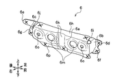
- the bulkhead 6 is a reinforcing member for reinforcing the split joint 21 e of the rail inner 21.
- the bulkhead 6 includes an inner side wall 6a, a front wall 6b, a rear wall 6c, a first front flange 6d, a first rear flange 6e, and a second front flange 6f, which will be described later.
- Second rear flange 6g bulk upper wall 6h, third front flange 6i, third rear flange 6j, recess 6k, spot gun insertion hole 6m, and hat-shaped cross section 6n (see FIG.
- the bulkhead 6 includes an inner side wall 6a fastened to the rail inner 21, a front wall 6b extending outward from the front end of the inner side wall 6a, and a rear side of the front wall 6b and the inner side wall 6a.
- a rear wall 6c extending from the end to the vehicle outer side, a first front flange 6d extending forward from the front wall 6b, and a first rear flange 6e extending rearward from the rear wall 6c, a hat-shaped cross section 6n Are configured.
- the inner side wall 6a is a vertical wall that forms the right side of the bulkhead 6, and is formed in a rectangular shape in a side view.
- a recess 6k is formed in the central portion of the inner side wall 6a, and a pair of front and rear spot gun insertion holes 6m and bolt insertion holes 6o are formed on the front and rear sides of the recess 6k.
- a split joint portion 21e of the front rail inner member 21A and the rear rail inner member 21B is disposed opposite to and fixed to the inner side wall 6a.
- the front wall 6 b is a wall that forms the front side surface of the bulkhead 6, and is formed by bending a flap extending forward from the inner wall 6 a vertically to the left.
- a third front flange 6i, a second front flange 6f and a first front flange 6d are formed on the upper and lower sides and the left side of the front wall 6b.
- the rear wall 6c is a wall that forms the rear side surface of the bulkhead 6, and is formed by bending a flap extending rearward from the inner side wall 6a vertically in the left direction.
- a third rear flange 6j, a second rear flange 6g and a first rear flange 6e are formed on the upper and lower sides and the left side of the rear wall 6c.
- the first front flange 6d is formed of a tongue piece bent so as to extend forward from the left end of the front wall 6b.
- the first rear flange 6e is formed of a tongue piece bent so as to extend rearward from the left end of the rear wall 6c.
- the first front flange 6d and the first rear flange 6e are joined to the vertical stiffener hanging wall 23b by spot welding.
- the second front flange 6f is formed of a tongue that is bent to extend forward from the lower end of the front wall 6b.
- the base end of the second front flange 6 f and the base end of the first front flange 6 d are continuously connected.
- the second rear flange 6g is formed of a tongue piece bent so as to extend rearward from the lower end of the rear wall 6c.
- the proximal end of the second rear flange 6g and the proximal end of the first rear flange 6e are continuously connected.
- the second front flange 6f and the second rear flange 6g are joined to the upper surface of the stiffener lower wall 23c by spot welding.
- the bulk upper wall 6h is a wall formed to extend horizontally outward from the upper end of the inner side wall 6a in the vehicle width direction. Two places of the front end portion and the rear end portion of the bulk upper wall 6 h are joined to the stiffener upper wall 23 a by spot welding.
- the third front flange 6i is formed of a tongue piece bent so as to extend rearward from the upper end of the front wall 6b.
- the third rear flange 6j is formed of a tongue piece bent so as to extend forward from the upper end of the rear wall 6c.
- the third front flange 6i and the third rear flange 6j are joined to the bulk upper wall 6h by spot welding.
- the concave portion 6k is formed in a concave shape toward the rail stiffener 23 (outside direction in the vehicle width direction) at a position overlapping the split joint portion 21e in the vehicle width direction on the inner side wall 6a. For this reason, even if the thickness of the divided joint portion 21e is increased by the recessed portion 6k being arranged by overlapping the front rail inner member 21A and the rear rail inner member 21B, the divided joint portion of the rear rail inner member 21B Since 21e is disposed in the recessed portion 6k, it does not bulge inside the vehicle.
- the spot gun insertion hole 6m inserts a spot gun 7 (see FIG. 9) for spot coupling the stiffener hanging wall 23b of the rail stiffener 23 and the flange upper end 52Ba of the pillar stiffener 52B. It is a hole for
- the rail stiffener 23 is joined to the outer side of the bulkhead 6 to form a closed cross section 6q, so that the strength of the rail stiffener 23 can be improved.
- the rail inner 21 is bolted to the inner side of the bulkhead 6, the strength of the rail inner 21 can be improved.
- the bolt insertion holes 6o and 6o are at positions matched with the bolt insertion holes 52Ab and 52Ab of the pillar inner 52A and the bolt insertion holes 21b and 21b of the front rail inner member 21A and the rear rail inner member 21B.
- the bolt 32 is inserted. In this way, the split joint portion 21e of the front rail inner member 21A and the rear rail inner member 21B is firmly connected.
- the lower flange 6 p is an extension formed at the lower edge of the bulkhead 6, and three places of the front end, the rear end and the center are the lower flanges 23 g of the rail stiffener 23. Are joined by spot welding.
- the bulkhead 6 is joined to the rail stiffener 23 and fastened to the rail inner 21 by the bolt 32 and the nut 31 so that the rail inner 21 at the intersection 2b where the pillar 5 and the roof side rail 2 intersect. It is attached between the rail stiffeners 23. That is, as shown in FIG. 4, the pillar inner 52A, the rail inner 21 and the bulkhead 6 are fastened together by the bolt 32 and the nut 31. In this manner, the bulkhead 6 installed in the roof side rail 2 is arranged to divide the closed cross section 2a between the rail inner 21 and the rail stiffener 23, as shown in FIG.
- the bolt 32 is a fastener which is inserted into the inner side of the rail inner 21 from the inner side of the pillar inner 52A, the rail inner 21 and the bulkhead 6 and fastened to the nut 31 and has, for example, an external thread 32a. It consists of a bolt with a seat. The nut 31 and the bolt 32 are attached so that the bulkhead 6 is superimposed on the rail inner 21 side of the closed cross section 2 a formed by the rail inner 21 and the rail outer 22. Therefore, the bolt 32, the nut 31 and the bulkhead 6 have a function of suppressing the cross-sectional deformation of the closed cross-section 2a to improve the rigidity and the strength.
- the center pillar 52 is a member constituting a tubular pillar which is a part of the vehicle body side portion 1a and the vehicle body upper portion 1d, and is formed by, for example, pressing a steel plate or the like.
- the center pillar 52 (pillar 5) includes a pillar inner 52A whose upper end is attached to the inner side surface of the rail inner 21 and a pillar stiffener 52B whose upper end is attached to the outer side surface of the rail stiffener 23.
- the pillar inner 52A joins, for example, a center pillar outer (not shown) and the pillar stiffener 52B to form a tubular closed cross section.
- the bolt insertion hole 52Ab and the flange upper end 52Aa are formed in the upper portion of the pillar inner 52A.
- the inner side of the pillar inner 52A is covered by a pillar garnish (not shown) which is an interior material.
- the pillar stiffener 52B is a reinforcing member for reinforcing the center pillar 52.
- the pillar stiffener 52B is interposed between a pillar inner 52A formed and extended downward from the roof side rail 2 in a tubular shape and a pillar outer (not shown), joined together by spot welding etc. ing.
- a flange upper end 52Ba joined to the rail stiffener 23 by spot welding or the like is formed on the front and rear upper peripheral edge of the upper end 52Bb of the pillar stiffener 52B.
- the fixed side electrode 8 (see FIG. 9) of the welding device is brought into contact with the pillar stiffener 52B from the vehicle outer side, and the spot gun 7 (see FIG. 9) of the welding device is pressed against the bulkhead 6 from the vehicle inner side;
- the central portions of the first front flange 6d, the first rear flange 6e and the lower flange 6p of the bulkhead 6 are joined to the stiffener hanging wall 23b and the lower flange 23g of the rail stiffener 23.
- the fixed side electrode 8 (see FIG. 9) of the welding apparatus is brought into contact with the stiffener lower wall 23c from the lower side of the rail stiffener 23 to make the spot gun 7 (see FIG. 9) as shown in FIG.
- the second front flange 6 f and the second rear flange 6 g of the bulkhead 6 and the lower stiffener wall 23 c of the rail stiffener 23 are joined from the upper side into the notches 23 d and 23 e of the rail stiffener 23.
- the bulk upper wall 6 h of the bulkhead 6 and the stiffener upper wall 23 a of the rail stiffener 23 are joined.
- the bulkhead 6 is bonded to the rail stiffener 23.
- a pillar stiffener 52 ⁇ / b> B is disposed outside the rail stiffener 23.
- the fixed side electrode 8 (see FIG. 9) of the welding device is brought into contact with the pillar stiffener 52B from the vehicle outer side, and the spot gun 7 (see FIG. 9) is inserted into the spot gun insertion holes 6m and 6m from the vehicle inner side.
- the stiffener hanging wall 23b of the rail stiffener 23 and the upper end 52Bb (see FIG. 3) of the pillar stiffener 52B are joined.
- the fixed side electrode 8 (see FIG. 9) of the welding device is brought into contact with the pillar stiffener 52B from the vehicle outer side, and the spot gun 7 (see FIG.
- the convex portion 21f of the rail inner 21 is inserted into the notches 23d to 23f of the rail stiffener 23, and the rail inner 21 and the rail stiffener 23 are aligned and positioned. Let Then, as shown in FIG. 8, the rail inner 21 and the bulkhead 6 are disposed below the stiffener upper wall 23 a of the rail stiffener 23.
- bolt insertion holes 6o and 6o of the bulkhead 6 are matched. Therefore, the bulkhead 6 is disposed on the vehicle outer side of the rail inner 21, and the pillar inner 52 ⁇ / b> A is disposed on the vehicle inner side of the rail inner 21.
- the bolts 32, 32 are inserted into the bolt insertion holes 52Ab, 52Ab of the pillar inner 52A, the bolt insertion holes 21b, 21b of the rail inner 21 and the bolt insertion holes 6o, 6o of the bulkhead 6, and fastened to the nut 31.
- the pillar inner 52 ⁇ / b> A, the rail inner 21, and the bulkhead 6 are fixed by the bolt 32 and the nut 31.
- the roof rail 12, the roof panel 11, and the outer upper flap portion 22 a of the rail outer 22 are joined to the upper side of the stiffener upper wall 23 a of the rail stiffener 23.
- An outer lower flap portion 22d of the rail outer 22 is joined to the flange upper end portion 52Ba of the pillar stiffener 52B.
- the bulkhead 6 is joined to the inner side of the rail stiffener 23 and the upper end 52Bb of the pillar stiffener 52B and is bolted to the outer side of the rail inner 21 and the pillar inner 52A.
- the rigidity and strength of the intersection 2b (see FIG. 3) with the center pillar 52 can be improved.
- the roof side rail 2 thus formed is further formed by the rail inner 21 and the rail stiffener 23 in the closed cross section 2 a formed by the rail inner 21 and the rail outer 22 as shown in FIG. Since the closed cross section 2a is formed, the rigidity and strength of the roof side rail 2 can be improved.
- the bulkhead 6 is fixed by the bolt 32 and the nut 31, and the rail inner 21 is reinforced. Furthermore, as shown in FIG. 9, the bulkhead 6 having a hat-shaped cross section 6 n has a closed cross section 6 q formed by closing the opening on the vehicle outer side with the rail stiffener 23. The rigidity and strength of the portion 2b can be further enhanced.
- the nut 31 screwed to the bolt 32 is internally installed in the bulkhead 6 disposed in the rail stiffener 23, so that the external shape of the rail outer 22 and the layout for installation are not affected.
- the design of the rail outer 22 can be improved.
- the left upper portion of the vehicle body where the roof side rail 2 and the center pillar 52 are joined is described as an example, but the present invention is not limited thereto.
- the present invention can also be applied to the joint portion between the roof side rail 2 and the pillar 5 such as the quarter pillar 53 or the rear pillar 54.
- the assembling order and the welding process described in the above-described embodiment are merely examples, and the operation may be performed in another order.
- the bulkhead 6, the rail stiffener 23 and the pillar stiffener 52B may be joined together in the same process.
Landscapes
- Engineering & Computer Science (AREA)
- Chemical & Material Sciences (AREA)
- Combustion & Propulsion (AREA)
- Transportation (AREA)
- Mechanical Engineering (AREA)
- Body Structure For Vehicles (AREA)
Abstract
Priority Applications (3)
| Application Number | Priority Date | Filing Date | Title |
|---|---|---|---|
| US14/890,979 US9452788B2 (en) | 2013-05-17 | 2014-03-25 | Top part structure of vehicle body |
| CN201480028513.1A CN105377674B (zh) | 2013-05-17 | 2014-03-25 | 车身上部结构 |
| JP2015516979A JP5947983B2 (ja) | 2013-05-17 | 2014-03-25 | 車体上部構造 |
Applications Claiming Priority (2)
| Application Number | Priority Date | Filing Date | Title |
|---|---|---|---|
| JP2013-104721 | 2013-05-17 | ||
| JP2013104721 | 2013-05-17 |
Publications (1)
| Publication Number | Publication Date |
|---|---|
| WO2014185154A1 true WO2014185154A1 (fr) | 2014-11-20 |
Family
ID=51898138
Family Applications (1)
| Application Number | Title | Priority Date | Filing Date |
|---|---|---|---|
| PCT/JP2014/058330 Ceased WO2014185154A1 (fr) | 2013-05-17 | 2014-03-25 | Structure de partie supérieure d'une carrosserie de véhicule |
Country Status (4)
| Country | Link |
|---|---|
| US (1) | US9452788B2 (fr) |
| JP (1) | JP5947983B2 (fr) |
| CN (1) | CN105377674B (fr) |
| WO (1) | WO2014185154A1 (fr) |
Cited By (2)
| Publication number | Priority date | Publication date | Assignee | Title |
|---|---|---|---|---|
| CN105235754A (zh) * | 2015-11-02 | 2016-01-13 | 北汽银翔汽车有限公司 | 顶盖与侧围焊接总成结构 |
| DE102017103993B4 (de) | 2016-04-25 | 2024-05-29 | Suzuki Motor Corporation | Dachlängsträger für ein fahrzeug |
Families Citing this family (17)
| Publication number | Priority date | Publication date | Assignee | Title |
|---|---|---|---|---|
| JPH089212B2 (ja) | 1987-08-11 | 1996-01-31 | 凸版印刷株式会社 | 貼り合わせ方法 |
| DE102015100263B3 (de) * | 2015-01-09 | 2016-03-31 | Audi Ag | Strukturbauteil für eine Karosserie eines Personenkraftwagens |
| JP6673163B2 (ja) * | 2016-11-28 | 2020-03-25 | トヨタ自動車株式会社 | 車両の中央部構造 |
| CN108528534A (zh) * | 2017-03-02 | 2018-09-14 | 标致雪铁龙集团 | 车身侧围总成与汽车顶盖的连接结构及汽车 |
| JP6575015B2 (ja) * | 2017-07-07 | 2019-09-18 | 本田技研工業株式会社 | 車体構造 |
| KR102506936B1 (ko) * | 2018-01-10 | 2023-03-07 | 현대자동차 주식회사 | 차체 구조 |
| RU180455U1 (ru) * | 2018-01-10 | 2018-06-14 | Публичное акционерное общество "АВТОВАЗ" | Конструкция кузова автомобиля в зоне соединения каркаса боковины и внутренней панели боковины |
| JP2019127099A (ja) * | 2018-01-23 | 2019-08-01 | トヨタ自動車株式会社 | 車両の上部車体構造 |
| JP7289434B2 (ja) * | 2019-06-17 | 2023-06-12 | マツダ株式会社 | 上部車体構造 |
| JP7170972B2 (ja) * | 2019-06-17 | 2022-11-15 | マツダ株式会社 | 上部車体構造 |
| KR102739178B1 (ko) * | 2019-12-05 | 2024-12-06 | 현대자동차주식회사 | 차량용 사이드아웃터구조 |
| KR102869056B1 (ko) * | 2020-08-10 | 2025-10-10 | 현대자동차 주식회사 | 센터 필러 구조 |
| JP7307043B2 (ja) * | 2020-12-09 | 2023-07-11 | トヨタ自動車株式会社 | 車体 |
| KR102934934B1 (ko) * | 2020-12-16 | 2026-03-05 | 현대자동차 주식회사 | 프레임 연결 구조 및 방법 |
| CN112623041B (zh) * | 2021-01-06 | 2025-12-30 | 蔚来汽车科技(安徽)有限公司 | 用于车身的b柱结构及车辆 |
| JP7401481B2 (ja) * | 2021-04-09 | 2023-12-19 | トヨタ自動車株式会社 | 車両 |
| FR3161630A1 (fr) * | 2024-04-25 | 2025-10-31 | Stellantis Auto Sas | Arrangement de caisse pour véhicule automobile |
Citations (2)
| Publication number | Priority date | Publication date | Assignee | Title |
|---|---|---|---|---|
| JP2006327399A (ja) * | 2005-05-26 | 2006-12-07 | Honda Motor Co Ltd | 車体のルーフ構造 |
| JP2013049376A (ja) * | 2011-08-31 | 2013-03-14 | Mazda Motor Corp | 車両の車体構造及びその製造方法 |
Family Cites Families (8)
| Publication number | Priority date | Publication date | Assignee | Title |
|---|---|---|---|---|
| JPS6023232Y2 (ja) * | 1982-01-11 | 1985-07-10 | マツダ株式会社 | 自動車のシ−トベルトアンカ−の取付部構造 |
| US8794693B2 (en) * | 2010-11-29 | 2014-08-05 | Honda Motor Co., Ltd. | Side structure for vehicle body |
| US9394018B2 (en) * | 2011-07-04 | 2016-07-19 | Honda Motor Co., Ltd. | Vehicle body structure and method for assembling vehicle body structure |
| EP2752358B1 (fr) * | 2011-08-31 | 2016-06-15 | Honda Motor Co., Ltd. | Structure supérieure de carrosserie de véhicule |
| JP5776451B2 (ja) * | 2011-08-31 | 2015-09-09 | マツダ株式会社 | 車両の車体構造 |
| JP6040630B2 (ja) * | 2012-04-11 | 2016-12-07 | マツダ株式会社 | 車両の側部車体構造 |
| KR101439147B1 (ko) * | 2013-04-19 | 2014-09-11 | 현대자동차주식회사 | 사이드 스트럭처와 루프레일의 결합 구조 및 방법 |
| JP6090241B2 (ja) * | 2014-06-18 | 2017-03-08 | マツダ株式会社 | サンルーフ付き自動車の上部車体構造 |
-
2014
- 2014-03-25 US US14/890,979 patent/US9452788B2/en not_active Expired - Fee Related
- 2014-03-25 CN CN201480028513.1A patent/CN105377674B/zh not_active Expired - Fee Related
- 2014-03-25 JP JP2015516979A patent/JP5947983B2/ja not_active Expired - Fee Related
- 2014-03-25 WO PCT/JP2014/058330 patent/WO2014185154A1/fr not_active Ceased
Patent Citations (2)
| Publication number | Priority date | Publication date | Assignee | Title |
|---|---|---|---|---|
| JP2006327399A (ja) * | 2005-05-26 | 2006-12-07 | Honda Motor Co Ltd | 車体のルーフ構造 |
| JP2013049376A (ja) * | 2011-08-31 | 2013-03-14 | Mazda Motor Corp | 車両の車体構造及びその製造方法 |
Cited By (2)
| Publication number | Priority date | Publication date | Assignee | Title |
|---|---|---|---|---|
| CN105235754A (zh) * | 2015-11-02 | 2016-01-13 | 北汽银翔汽车有限公司 | 顶盖与侧围焊接总成结构 |
| DE102017103993B4 (de) | 2016-04-25 | 2024-05-29 | Suzuki Motor Corporation | Dachlängsträger für ein fahrzeug |
Also Published As
| Publication number | Publication date |
|---|---|
| CN105377674A (zh) | 2016-03-02 |
| US20160083018A1 (en) | 2016-03-24 |
| US9452788B2 (en) | 2016-09-27 |
| JP5947983B2 (ja) | 2016-07-06 |
| CN105377674B (zh) | 2017-09-29 |
| JPWO2014185154A1 (ja) | 2017-02-23 |
Similar Documents
| Publication | Publication Date | Title |
|---|---|---|
| JP5947983B2 (ja) | 車体上部構造 | |
| US8690227B2 (en) | Lower vehicle-body structure of vehicle | |
| EP2412611B1 (fr) | Structure pour partie supérieure de carrosserie de véhicule | |
| US10625788B2 (en) | Vehicle side section structure | |
| JP4847985B2 (ja) | 車体上部構造及びガセットの取付方法 | |
| JP6022682B2 (ja) | 車体上部構造 | |
| JP5776560B2 (ja) | 自動車の車体前部構造 | |
| US20160194031A1 (en) | Vehicle body front portion structure | |
| US20160107701A1 (en) | Vehicle body structure | |
| KR20130125802A (ko) | 수지 루프 패널 구조 | |
| JP4704738B2 (ja) | 車両の後部車体構造 | |
| JP3610927B2 (ja) | 自動車の車体上部構造 | |
| JP6698393B2 (ja) | 車体側部構造 | |
| US20150251701A1 (en) | Vehicle rear structure | |
| JP6110834B2 (ja) | 車体側部構造 | |
| JP5136025B2 (ja) | フェンダーパネルの固定構造 | |
| JP6122824B2 (ja) | 車体上部構造 | |
| JP2010228501A (ja) | 車室前部の車体構造 | |
| JP2008087609A (ja) | 車両のリヤピラー上部の補強構造 | |
| CN204355159U (zh) | 车体前部结构 | |
| JP2018062255A (ja) | 自動車のサイドボディ構造 | |
| WO2015072405A1 (fr) | Structure de carrosserie de véhicule | |
| JP2016088135A (ja) | 自動車のピラー補強構造 | |
| JPH09277955A (ja) | 自動車のサイドパネル補強構造 | |
| JP2004299669A (ja) | 車体骨格構造 |
Legal Events
| Date | Code | Title | Description |
|---|---|---|---|
| 121 | Ep: the epo has been informed by wipo that ep was designated in this application |
Ref document number: 14797990 Country of ref document: EP Kind code of ref document: A1 |
|
| ENP | Entry into the national phase |
Ref document number: 2015516979 Country of ref document: JP Kind code of ref document: A |
|
| WWE | Wipo information: entry into national phase |
Ref document number: 14890979 Country of ref document: US |
|
| NENP | Non-entry into the national phase |
Ref country code: DE |
|
| 122 | Ep: pct application non-entry in european phase |
Ref document number: 14797990 Country of ref document: EP Kind code of ref document: A1 |