WO2014185292A1 - 電動式直動アクチュエータおよび電動ブレーキ装置 - Google Patents
電動式直動アクチュエータおよび電動ブレーキ装置 Download PDFInfo
- Publication number
- WO2014185292A1 WO2014185292A1 PCT/JP2014/062153 JP2014062153W WO2014185292A1 WO 2014185292 A1 WO2014185292 A1 WO 2014185292A1 JP 2014062153 W JP2014062153 W JP 2014062153W WO 2014185292 A1 WO2014185292 A1 WO 2014185292A1
- Authority
- WO
- WIPO (PCT)
- Prior art keywords
- electric motor
- pressing force
- rotational torque
- electric
- value
- Prior art date
- Legal status (The legal status is an assumption and is not a legal conclusion. Google has not performed a legal analysis and makes no representation as to the accuracy of the status listed.)
- Ceased
Links
Images


Classifications
-
- F—MECHANICAL ENGINEERING; LIGHTING; HEATING; WEAPONS; BLASTING
- F16—ENGINEERING ELEMENTS AND UNITS; GENERAL MEASURES FOR PRODUCING AND MAINTAINING EFFECTIVE FUNCTIONING OF MACHINES OR INSTALLATIONS; THERMAL INSULATION IN GENERAL
- F16D—COUPLINGS FOR TRANSMITTING ROTATION; CLUTCHES; BRAKES
- F16D65/00—Parts or details
- F16D65/14—Actuating mechanisms for brakes; Means for initiating operation at a predetermined position
- F16D65/16—Actuating mechanisms for brakes; Means for initiating operation at a predetermined position arranged in or on the brake
- F16D65/18—Actuating mechanisms for brakes; Means for initiating operation at a predetermined position arranged in or on the brake adapted for drawing members together, e.g. for disc brakes
-
- B—PERFORMING OPERATIONS; TRANSPORTING
- B60—VEHICLES IN GENERAL
- B60T—VEHICLE BRAKE CONTROL SYSTEMS OR PARTS THEREOF; BRAKE CONTROL SYSTEMS OR PARTS THEREOF, IN GENERAL; ARRANGEMENT OF BRAKING ELEMENTS ON VEHICLES IN GENERAL; PORTABLE DEVICES FOR PREVENTING UNWANTED MOVEMENT OF VEHICLES; VEHICLE MODIFICATIONS TO FACILITATE COOLING OF BRAKES
- B60T13/00—Transmitting braking action from initiating means to ultimate brake actuator with power assistance or drive; Brake systems incorporating such transmitting means, e.g. air-pressure brake systems
- B60T13/74—Transmitting braking action from initiating means to ultimate brake actuator with power assistance or drive; Brake systems incorporating such transmitting means, e.g. air-pressure brake systems with electrical assistance or drive
- B60T13/741—Transmitting braking action from initiating means to ultimate brake actuator with power assistance or drive; Brake systems incorporating such transmitting means, e.g. air-pressure brake systems with electrical assistance or drive acting on an ultimate actuator
-
- F—MECHANICAL ENGINEERING; LIGHTING; HEATING; WEAPONS; BLASTING
- F16—ENGINEERING ELEMENTS AND UNITS; GENERAL MEASURES FOR PRODUCING AND MAINTAINING EFFECTIVE FUNCTIONING OF MACHINES OR INSTALLATIONS; THERMAL INSULATION IN GENERAL
- F16D—COUPLINGS FOR TRANSMITTING ROTATION; CLUTCHES; BRAKES
- F16D55/00—Brakes with substantially-radial braking surfaces pressed together in axial direction, e.g. disc brakes
- F16D55/02—Brakes with substantially-radial braking surfaces pressed together in axial direction, e.g. disc brakes with axially-movable discs or pads pressed against axially-located rotating members
- F16D55/22—Brakes with substantially-radial braking surfaces pressed together in axial direction, e.g. disc brakes with axially-movable discs or pads pressed against axially-located rotating members by clamping an axially-located rotating disc between movable braking members, e.g. movable brake discs or brake pads
- F16D55/224—Brakes with substantially-radial braking surfaces pressed together in axial direction, e.g. disc brakes with axially-movable discs or pads pressed against axially-located rotating members by clamping an axially-located rotating disc between movable braking members, e.g. movable brake discs or brake pads with a common actuating member for the braking members
- F16D55/225—Brakes with substantially-radial braking surfaces pressed together in axial direction, e.g. disc brakes with axially-movable discs or pads pressed against axially-located rotating members by clamping an axially-located rotating disc between movable braking members, e.g. movable brake discs or brake pads with a common actuating member for the braking members the braking members being brake pads
-
- H—ELECTRICITY
- H02—GENERATION; CONVERSION OR DISTRIBUTION OF ELECTRIC POWER
- H02P—CONTROL OR REGULATION OF ELECTRIC MOTORS, ELECTRIC GENERATORS OR DYNAMO-ELECTRIC CONVERTERS; CONTROLLING TRANSFORMERS, REACTORS OR CHOKE COILS
- H02P7/00—Arrangements for regulating or controlling the speed or torque of electric DC motors
- H02P7/06—Arrangements for regulating or controlling the speed or torque of electric DC motors for regulating or controlling an individual DC dynamo-electric motor by varying field or armature current
- H02P7/18—Arrangements for regulating or controlling the speed or torque of electric DC motors for regulating or controlling an individual DC dynamo-electric motor by varying field or armature current by master control with auxiliary power
- H02P7/24—Arrangements for regulating or controlling the speed or torque of electric DC motors for regulating or controlling an individual DC dynamo-electric motor by varying field or armature current by master control with auxiliary power using discharge tubes or semiconductor devices
- H02P7/28—Arrangements for regulating or controlling the speed or torque of electric DC motors for regulating or controlling an individual DC dynamo-electric motor by varying field or armature current by master control with auxiliary power using discharge tubes or semiconductor devices using semiconductor devices
- H02P7/285—Arrangements for regulating or controlling the speed or torque of electric DC motors for regulating or controlling an individual DC dynamo-electric motor by varying field or armature current by master control with auxiliary power using discharge tubes or semiconductor devices using semiconductor devices controlling armature supply only
-
- F—MECHANICAL ENGINEERING; LIGHTING; HEATING; WEAPONS; BLASTING
- F16—ENGINEERING ELEMENTS AND UNITS; GENERAL MEASURES FOR PRODUCING AND MAINTAINING EFFECTIVE FUNCTIONING OF MACHINES OR INSTALLATIONS; THERMAL INSULATION IN GENERAL
- F16D—COUPLINGS FOR TRANSMITTING ROTATION; CLUTCHES; BRAKES
- F16D2121/00—Type of actuator operation force
- F16D2121/18—Electric or magnetic
- F16D2121/24—Electric or magnetic using motors
-
- F—MECHANICAL ENGINEERING; LIGHTING; HEATING; WEAPONS; BLASTING
- F16—ENGINEERING ELEMENTS AND UNITS; GENERAL MEASURES FOR PRODUCING AND MAINTAINING EFFECTIVE FUNCTIONING OF MACHINES OR INSTALLATIONS; THERMAL INSULATION IN GENERAL
- F16D—COUPLINGS FOR TRANSMITTING ROTATION; CLUTCHES; BRAKES
- F16D2125/00—Components of actuators
- F16D2125/18—Mechanical mechanisms
- F16D2125/20—Mechanical mechanisms converting rotation to linear movement or vice versa
- F16D2125/34—Mechanical mechanisms converting rotation to linear movement or vice versa acting in the direction of the axis of rotation
- F16D2125/40—Screw-and-nut
-
- F—MECHANICAL ENGINEERING; LIGHTING; HEATING; WEAPONS; BLASTING
- F16—ENGINEERING ELEMENTS AND UNITS; GENERAL MEASURES FOR PRODUCING AND MAINTAINING EFFECTIVE FUNCTIONING OF MACHINES OR INSTALLATIONS; THERMAL INSULATION IN GENERAL
- F16D—COUPLINGS FOR TRANSMITTING ROTATION; CLUTCHES; BRAKES
- F16D2125/00—Components of actuators
- F16D2125/18—Mechanical mechanisms
- F16D2125/44—Mechanical mechanisms transmitting rotation
- F16D2125/46—Rotating members in mutual engagement
- F16D2125/48—Rotating members in mutual engagement with parallel stationary axes, e.g. spur gears
-
- F—MECHANICAL ENGINEERING; LIGHTING; HEATING; WEAPONS; BLASTING
- F16—ENGINEERING ELEMENTS AND UNITS; GENERAL MEASURES FOR PRODUCING AND MAINTAINING EFFECTIVE FUNCTIONING OF MACHINES OR INSTALLATIONS; THERMAL INSULATION IN GENERAL
- F16D—COUPLINGS FOR TRANSMITTING ROTATION; CLUTCHES; BRAKES
- F16D2125/00—Components of actuators
- F16D2125/18—Mechanical mechanisms
- F16D2125/44—Mechanical mechanisms transmitting rotation
- F16D2125/46—Rotating members in mutual engagement
- F16D2125/50—Rotating members in mutual engagement with parallel non-stationary axes, e.g. planetary gearing
-
- F—MECHANICAL ENGINEERING; LIGHTING; HEATING; WEAPONS; BLASTING
- F16—ENGINEERING ELEMENTS AND UNITS; GENERAL MEASURES FOR PRODUCING AND MAINTAINING EFFECTIVE FUNCTIONING OF MACHINES OR INSTALLATIONS; THERMAL INSULATION IN GENERAL
- F16H—GEARING
- F16H25/00—Gearings comprising primarily only cams, cam-followers and screw-and-nut mechanisms
- F16H25/18—Gearings comprising primarily only cams, cam-followers and screw-and-nut mechanisms for conveying or interconverting oscillating or reciprocating motions
- F16H25/20—Screw mechanisms
- F16H25/2021—Screw mechanisms with means for avoiding overloading
Definitions
- the present invention uses an electric linear actuator that converts rotational torque generated by an electric motor into a linear force by a motion conversion mechanism and applies a pressing force to an object with the linear force, and the electric linear actuator.
- the present invention relates to an electric brake device.
- a hydraulic brake device that generates a braking force by pressing a friction pad against a brake disk with a hydraulic cylinder has been adopted.
- brake control such as ABS (anti-lock brake system).
- Electric brake devices that do not use a hydraulic circuit have attracted attention.
- the electric brake device has an electric linear actuator that uses an electric motor as a drive source, and generates a braking force by pressing a friction pad against a brake disk with the electric linear actuator.
- Patent Document 1 As such an electric brake device, for example, the one described in Patent Document 1 below is known.
- Patent Document 1 as an electric linear actuator that presses a friction pad against a brake disk, an electric motor and rotational torque generated by the electric motor are converted into a linear force of the linear member, and the friction pad is moved by the linear member.
- a mechanism having a motion conversion mechanism that presses against the brake disc and a load sensor that detects the magnitude of the pressing force applied to the brake disc is employed.
- the rotational torque of the electric motor is controlled based on the magnitude of the pressing force detected by the load sensor.
- the problem to be solved by the present invention is to provide an electric linear actuator with low power consumption.
- the motion conversion mechanism that converts the rotational torque of the electric motor into the linear force of the linear motion member and applies a pressing force to the object with the linear motion member
- the motion conversion mechanism is based on the reaction force that acts on the linear motion member from the target object.
- a large frictional force is generated inside. This frictional force causes energy loss and is generally undesirable.
- the inventor of the present application has focused on the possibility that the frictional force, which is generally undesirable, can be used for holding the pressing force in order to reduce the power consumption of the electric linear actuator. That is, the motion conversion mechanism that converts the rotational torque of the electric motor into the linear force of the linear motion member and applies a pressing force to the object with the linear motion member is the magnitude of the pressure applied to the target from the linear motion member. In many cases, hysteresis characteristics are exhibited when the value is changed. Hysteresis characteristics are applied in the process of increasing the rotational torque of the electric motor and in the process of decreasing the rotational torque of the electric motor, even if the pressing force applied to the object from the linear motion member is the same.
- the magnitude of the rotational torque of the electric motor is not the same, and the former is larger than the latter. This characteristic is mainly caused by the frictional force inside the motion conversion mechanism.
- the inventor of the present application has realized the possibility of reducing the power consumption of the electric motor by controlling the drive current of the electric motor in consideration of the hysteresis characteristics of the motion conversion mechanism.
- An electric motor that generates rotational torque of a magnitude according to the drive current
- a motion conversion mechanism that converts the rotational torque of the electric motor into a linear force of the linear motion member, and applies a pressing force to the object with the linear motion member
- a load sensor for detecting the magnitude of the pressing force applied to the object
- a motor control device that controls the drive current of the electric motor based on the magnitude of the pressing force detected by the load sensor
- the motion conversion mechanism has a process in which the rotational torque of the electric motor increases and a process in which the rotational torque of the electric motor decreases.
- Adopt the one that shows the hysteresis characteristics that the magnitude of the rotational torque of the electric motor when loading pressure is not the same, the former is greater than the latter
- the pressing force reaches the target value when the pressing force reaches the target value while the rotational torque of the electric motor decreases and when the rotating torque of the electric motor increases.
- the target value is the same as when the target value is reached, the magnitude of the rotational torque of the electric motor when the pressing force reaches the target value is not the same, and the former is smaller than the latter.
- the motor control device performs control so that the pressing force reaches the target value in the process of reducing the rotational torque of the electric motor when the pressing force is loaded and held on the object. Therefore, the rotational torque of the electric motor when the pressing force reaches the target value can be suppressed, and then the electric power consumption of the electric motor required to hold the pressing force at the target value can be reduced.
- the target value may be a load command value input from the outside to the motor control device
- the predetermined value may be a value set larger than the load command value with a predetermined offset value. That is, when the load command value is input from the outside, the motor control device reaches a value in which the magnitude of the pressing force detected by the load sensor is set larger than the load command value with a predetermined offset value. The rotational torque of the electric motor is increased until the magnitude of the pressing force detected by the load sensor reaches the load command value, and then the rotational torque of the electric motor is decreased. What controls the drive current of an electric motor so that it may hold
- the target value may be a value set smaller than a load command value input to the motor control device with a predetermined offset value
- the predetermined value may be the load command value. That is, after the load command value is input from the outside, the motor control device increases the rotational torque of the electric motor until the magnitude of the pressing force detected by the load sensor reaches the load command value. The rotational torque of the electric motor is reduced until the magnitude of the pressing force detected by the load sensor reaches a value set with a predetermined offset value smaller than the load command value, and then the pressing force is maintained. Further, it is possible to employ a device that controls the drive current of the electric motor.
- the electric motor includes a rotor that is rotatably supported and a stator that generates torque in the rotor, and the rotor and the stator have torque generated in the rotor while the rotor makes one rotation with respect to the stator. It is possible to adopt a configuration in which the maximum rotational phase and the rotational phase at which the torque generated in the rotor is minimized appear alternately. Furthermore, a phase sensor for detecting the rotational phase of the rotor can be provided. At this time, when the motor control device holds the pressing force detected by the load sensor at a target value, the pressing force coincides with the target value in a rotation phase in which the torque generated in the rotor is maximum. It is preferable that the drive current of the electric motor be controlled so that the rotor stops at the rotational phase closest to this phase. In this way, when a pressing force is applied to the object, the magnitude of the pressing force can be stably maintained.
- the above-described control for stopping the rotor at the rotational phase at which the torque is maximum can be performed only when the target value of the pressing force is greater than a preset threshold value. Thereby, even when the target value of the pressing force is relatively small, a stable pressing force can be obtained.
- the motion conversion mechanism includes a rotating shaft to which the rotational torque of the electric motor is input, a plurality of planetary rollers that are in rolling contact with the outer peripheral cylindrical surface of the rotating shaft, and arranged so as to surround the plurality of planetary rollers.
- a roller mechanism can be employed. In this case, since the planetary roller mechanism has a function of a speed reduction mechanism, the planetary roller mechanism as the motion conversion mechanism exhibits the above hysteresis characteristics remarkably. Therefore, the power consumption of the electric motor can be effectively reduced by applying the above control to the electric linear actuator using the planetary roller mechanism.
- the object is a brake disk that rotates integrally with a wheel, and the electric motor is used as an actuator that presses the friction pad against the brake disk.
- An electric brake device using a linear actuator is provided.
- the electric linear actuator of the present invention is configured to reduce the electric motor drive current so that the pressing force reaches a target value in the process of reducing the rotational torque of the electric motor when the pressing force is applied to an object and held. Since the control is performed, the rotational torque of the electric motor when the pressing force reaches the target value is smaller than in the normal control in which the pressing force reaches the target value in the process of increasing the rotational torque of the electric motor. Therefore, the drive current of the electric motor when holding the pressing force at the target value can be suppressed, and the power consumption of the electric motor is low.
- Sectional drawing which shows the electric brake device incorporating the electric type linear actuator of embodiment of this invention Sectional view along the line II-II in FIG. Sectional view along line III-III in FIG.
- Fig. 1 is an enlarged sectional view of the vicinity of the electric linear actuator Sectional view along line VV in FIG.
- FIG. 4 is an enlarged cross-sectional view in the vicinity of the load sensor.
- the block diagram of the motor control apparatus which controls the drive current of the electric motor shown in FIG. Flow chart showing an example of control by the motor control device shown in FIG.
- the flowchart which shows the other example of control by the motor control apparatus shown in FIG.
- the figure which shows the correspondence of the rotational torque of an electric motor when the drive current of an electric motor is controlled according to the control flow shown in FIG.
- FIG. 1 shows an electric brake device for a vehicle using an electric linear actuator 1 according to an embodiment of the present invention.
- the electric brake device includes a caliper body 6 having a shape in which opposed pieces 3 and 4 that are opposed to each other with a brake disc 5 that rotates integrally with a wheel interposed therebetween by a bridge 5, and between the opposed pieces 3 and 4 and the brake disc 2. And a pair of left and right friction pads 7 and 8, and an electric linear actuator 1 assembled to one opposing piece 3.
- the caliper body 6 is supported so as to be slidable in the axial direction of the brake disc 2 by a mount 9 (see FIG. 2) fixed to a knuckle (not shown) that supports the wheel.
- the friction pads 7 and 8 are also supported so as to be movable in the axial direction of the brake disk 2.
- the electric linear actuator 1 includes an electric motor 10, a motion conversion mechanism 11 that converts the rotational torque of the electric motor 10 into a linear force, and the magnitude of the pressing force applied to the brake disk 2. And a load sensor 12 for detecting.
- the electric motor 10 has a rotor 13 and a stator 14.
- the rotor 13 includes a motor shaft 16 rotatably supported by a bearing 15 and a rotor core 17 fixed to the motor shaft 16.
- the stator 14 includes a plurality of teeth 18 arranged at equal intervals in the circumferential direction so as to surround the rotor core 17, and an electromagnetic coil 19 wound around each tooth 18.
- the stator 14 generates a rotational torque in the rotor 13 by electromagnetic force acting between the teeth 18 and the rotor core 17 when the electromagnetic coil 19 is energized.
- the rotational torque generated in the rotor 13 has a magnitude corresponding to the drive current flowing through the electromagnetic coil 19. That is, the drive current of the electromagnetic coil 19 and the rotational torque of the electric motor 10 have a substantially proportional correlation, and the rotational torque generated in the rotor 13 increases monotonously as the current applied to the electromagnetic coil 19 monotonously increases.
- the magnitude of the rotational torque generated in the rotor 13 is not completely constant while the rotor 13 makes one rotation with respect to the stator 14, and slightly increases or decreases according to the rotational phase of the rotor 13. That is, while the rotor 13 makes one rotation with respect to the stator 14, the rotational phase in which the rotational torque generated in the rotor 13 is maximum and the rotational phase in which the rotational torque generated in the rotor 13 is minimum are the teeth 18 and the rotor core 17. It appears alternately according to the position change.
- the motion conversion mechanism 11 has a rotary shaft 20 arranged in parallel with the electric motor 10.
- a gear 21 is attached to the rotary shaft 20.
- the gear 21 meshes with a gear 23 attached to the motor shaft 16 of the electric motor 10 via an intermediate gear 22 that is rotatably supported.
- the rotational torque generated by the electric motor 10 is the gear 23, the intermediate gear. 22 and the gear 21 are transmitted in order and input to the rotary shaft 20.
- the motion conversion mechanism 11 includes a rotary shaft 20 to which rotational torque of the electric motor 10 is input, an outer ring member 24 that is provided coaxially so as to surround the rotary shaft 20, and the rotary shaft 20.
- a plurality of planetary rollers 25 that are circumscribed and inscribed in the outer ring member 24 at the same time, and a carrier 26 that holds the planetary rollers 25 so as to be capable of rotating and revolving.
- the outer ring member 24 is accommodated in an accommodation hole 27 formed in the facing piece 3 and is supported by the inner surface of the accommodation hole 27 so as to be movable in the axial direction.
- An engagement convex portion 28 is formed at the front end in the axial direction of the outer ring member 24.
- An engagement recess 29 that engages with the engagement protrusion 28 is formed on the back surface of the friction pad 7. The outer ring member 24 is prevented from rotating by the engagement of the engagement convex portion 28 and the engagement concave portion 29.
- a plurality of planetary rollers 25 are arranged at regular intervals in the circumferential direction.
- Each planetary roller 25 is in rolling contact with the outer periphery of the rotating shaft 20 and the inner periphery of the outer ring member 24.
- the outer periphery of the rotating shaft 20 is a cylindrical surface.
- the planetary roller 25 revolves while rotating between the rotating shaft 20 and the outer ring member 24. That is, the planetary roller 25 rotates by the rotational force received from the outer periphery of the rotating shaft 20 and revolves by rolling the inner periphery of the outer ring member 24 at the same time.
- a spiral ridge 30 is provided on the inner periphery of the outer ring member 24.
- the spiral protrusion 30 is a spiral protrusion extending obliquely with respect to the circumferential direction.
- a circumferential groove 31 that engages with the spiral ridge 30 is provided on the outer periphery of the planetary roller 25.
- the circumferential groove 31 having a lead angle of 0 degrees is provided on the outer periphery of the planetary roller 25.
- a spiral groove having a lead angle different from that of the spiral protrusion 30 may be provided. Good.
- the carrier 26 has a plurality of carrier pins 26A passing through the centers of the plurality of planetary rollers 25 in the axial direction and an annular shape connecting the respective axial front ends of the plurality of carrier pins 26A to each other.
- the carrier plate 26C includes an annular carrier body 26B that connects the axial rear ends of the plurality of carrier pins 26A to each other.
- Each carrier pin 26A supports the planetary roller 25 via a bearing 32 so as to be able to rotate.
- a reduced-diameter ring spring 33 is attached to each end of each carrier pin 26A.
- the reduced-diameter ring spring 33 is mounted so as to circumscribe all the carrier pins 26A arranged at intervals in the circumferential direction.
- the reduced diameter ring spring 33 urges each carrier pin 26A radially inward, presses the planetary roller 25 against the outer periphery of the rotating shaft 20 by the urging force, and slips between the rotating shaft 20 and the planetary roller 25. To prevent.
- a sliding bearing 34 is attached to the inner periphery of the carrier body 26B.
- the carrier body 26 ⁇ / b> B is supported by the rotary shaft 20 via the sliding bearing 34 and is rotatable relative to the rotary shaft 20.
- a thrust bearing 35 is incorporated between the carrier body 26B and each planetary roller 25 to support the planetary roller 25 so that it can rotate.
- the carrier plate 26C and the carrier main body 26B are connected between adjacent planetary rollers 25 by a connecting rod 36 extending in the axial direction, and by this connection, both the carrier plate 26C and the carrier main body 26B rotate integrally. .
- the load sensor 12 includes an annular plate-shaped flange member 40 and a support member 41 that face each other in the axial direction, a magnetic target 42 that generates a magnetic field, and a magnetic sensor 43 that detects the strength of the magnetic field.
- the magnetic target 42 is fixed to the flange member 40
- the magnetic sensor 43 is fixed to the support member 41.
- the magnetic target 42 and the magnetic sensor 43 are arranged to face each other so that the output of the magnetic sensor 43 changes due to the bending deformation of the flange member 40 when an axial load is input to the flange member 40. As shown in FIG.
- the magnetic target 42 includes two permanent magnets 44, 44 having a magnetization direction in a direction perpendicular to the relative displacement direction of the magnetic target 42 and the magnetic sensor 43.
- the N pole and the S pole of the other permanent magnet 44 are arranged adjacent to each other.
- the magnetic sensor 43 is disposed in the vicinity of the boundary between adjacent magnetic poles of the two permanent magnets 44 constituting the magnetic target 42.
- a spacer 45 that revolves integrally with the carrier 26 and a thrust bearing 46 that transmits an axial load between the spacer 45 and the flange member 40 are incorporated between the carrier 26 and the flange member 40.
- a rolling bearing 47 that rotatably supports the rotating shaft 20 is incorporated in the inner periphery of the flange member 40.
- the load sensor 12 is configured to lock the outer peripheral edges of the flange member 40 and the support member 41 with retaining rings 48 and 49 attached to the inner periphery of the accommodation hole 27, thereby moving the front and rear in the axial direction. Movement to is restricted.
- the load sensor 12 supports the carrier body 26 ⁇ / b> B in the axial direction via the spacer 45 and the thrust bearing 46, thereby restricting the movement of the carrier 26 rearward in the axial direction.
- the carrier 26 is also restricted from moving forward in the axial direction by a retaining ring 50 attached to the front end of the rotating shaft 20 in the axial direction. Therefore, the carrier 26 is restricted from moving in the axial direction forward and axially backward, and the planetary roller 25 held by the carrier 26 is also restricted from moving in the axial direction.
- the motion converting mechanism 11 revolves around the rotating shaft 20 while the planetary roller 25 rotates around the carrier pin 26A.
- the outer ring member 24 and the planetary roller 25 move relative to each other in the axial direction due to the engagement between the spiral ridge 30 and the circumferential groove 31, but the planetary roller 25 is restricted from moving in the axial direction together with the carrier 26.
- the roller 25 does not move in the axial direction, and the outer ring member 24 moves in the axial direction.
- the motion conversion mechanism 11 converts the rotational torque of the electric motor 10 into the axially linear force of the outer ring member 24, and the friction pad 7 is pressed against the brake disk 2 by the outer ring member 24, so that the brake disk 2 Apply pressing force.
- the outer ring member 24 receives an axial reaction force from the brake disk 2 via the friction pad 7, and the reaction force is transmitted to the flange member 40 via the planetary roller 25, the carrier 26, the spacer 45, and the thrust bearing 46.
- the flange member 40 bends in the axial direction rearward by the reaction force, and the relative position of the magnetic target 42 and the magnetic sensor 43 changes. Since the output signal of the magnetic sensor 43 changes according to the change in the relative position, the magnitude of the pressing force applied to the brake disk 2 can be detected based on the output signal of the magnetic sensor 43.
- the electric motor 10 is connected to a motor control device 51 shown in FIG.
- the motor control device 51 controls the drive current of the electric motor 10 based on the magnitude of the pressing force detected by the load sensor 12.
- the motor control device 51 receives the load command value F from the brake ECU 52, receives a signal indicating the magnitude of the pressing force from the load sensor 12, and indicates the rotational phase of the rotor 13 of the electric motor 10 from the phase sensor 53. A signal is input.
- the brake ECU 52 is an electronic control unit that controls the electric brake device for each wheel based on the amount of operation of the brake pedal by the driver of the vehicle.
- the phase sensor 53 is a power supply device that estimates the rotational phase of the rotor 13 based on, for example, a line voltage that supplies power to the electric motor 10. Further, as the phase sensor 53, a resolver or a hall element incorporated in the electric motor 10 can be adopted.
- this electric brake device applies a pressing force from the outer ring member 24 to the brake disc 2 by applying a current to the electric motor 10 and then continuously applies a constant current to the electric motor 10 to thereby apply a brake.
- the magnitude of the pressing force applied to the disk 2 can be kept constant. If the magnitude of the drive current of the electric motor 10 at this time can be reduced, the power consumption of the electric motor 10 can be effectively suppressed.
- the motion conversion mechanism 11 exhibits a hysteresis characteristic when the magnitude of the pressing force applied to the brake disk 2 from the outer ring member 24 is changed.
- the hysteresis characteristic is a process in which the rotational torque of the electric motor 10 increases and a process in which the rotational torque of the electric motor 10 decreases, even if the pressure applied to the brake disk 2 from the outer ring member 24 is the same.
- the rotational torque of the electric motor 10 when the load is applied is not the same, and the former is larger than the latter. This characteristic is mainly caused by the frictional force inside the motion conversion mechanism 11.
- said motor control apparatus 51 loads and hold
- the drive current of the electric motor 10 is controlled so that the rotational torque of the electric motor 10 is decreased until the magnitude of the pressing force detected by the load sensor 12 reaches the target value.
- the motor control device 51 first detects the pressing force detected by the load sensor 12.
- the rotational torque of the electric motor 10 is increased until the magnitude reaches a value (F + df) set larger than the load command value F with a predetermined offset value df (steps S 2 and S 3 ).
- the rotational torque of the electric motor 10 is decreased until the magnitude of the pressing force detected at 12 reaches the load command value F (steps S 4 and S 5 ), and then the rotational torque of the electric motor 10 is maintained.
- the offset value df is a minute value set sufficiently smaller than the load command value F.
- This control can reduce the power consumption of the electric motor 10. That is, as shown in FIG. 10, increasing the rotational torque of the electric motor 10 from zero, the pressing force is increased along a straight line L 1 showing the normal efficiency. Thereafter, when the rotational torque of the electric motor 10 turns to decrease, and the state remained along line L 2, showing a non-linear hysteresis characteristic magnitude of the pressing force is hardly changed until it reaches the straight line L 3. Furthermore, reducing the rotational torque of the electric motor 10, the pressing force is reduced along a straight line L 3 showing a negative efficiency.
- the pressing force is a load command value F in the process L 1 of rotation torque increases of the electric motor 10
- the load command value F is the same as when the load command value F is reached, the magnitude of the rotational torque of the electric motor 10 when the pressing force reaches the load command value F is not the same.
- the pressing force is set to the load command value F in the rotation phase in which the torque generated in the rotor 13 becomes maximum. It is preferable to control the drive current of the electric motor 10 so that the rotor 13 stops at the rotational phase closest to the phase when they coincide. That is, when the rotational torque of the electric motor 10 is decreased until the magnitude of the pressing force detected by the load sensor 12 reaches the load command value F, the pressing force detected by the load sensor 12 becomes the load command value F.
- the pressing force is the load command in the rotational phase where the torque generated in the rotor 13 becomes maximum while the rotor 13 makes one rotation with respect to the stator 14.
- the drive current of the electric motor 10 is controlled so that the rotor 13 stops at the rotational phase closest to the phase when the value F matches.
- the above-described control for stopping the rotor 13 at the rotational phase at which the torque is maximum can be performed only when the load command value F is larger than a preset threshold value. Thereby, a stable pressing force can be obtained even when the load command value F is relatively small.
- the motor control device 51 first detects the pressing detected by the load sensor 12.
- the rotational torque of the electric motor 10 is increased until the pressure reaches the load command value F (steps S 2 and S 3 ), and then the magnitude of the pressing force detected by the load sensor 12 is the load command value.
- the rotational torque of the electric motor 10 is decreased until it reaches a value (F ⁇ df) set to be smaller than a predetermined offset value df than F (steps S 4 and S 5 ), and then the rotational torque of the electric motor 10 is reduced. It may be controlled driving current of the electric motor 10 so as to hold (step S 6).
- the motor control device 51 holds the pressing force detected by the load sensor 12 at a target value set smaller than the load command value F by a predetermined offset value df, the torque generated in the rotor 13 is maximum.
- the drive current of the electric motor 10 is preferably controlled so that the rotor 13 stops at the rotational phase closest to the phase when the pressing force matches the target value (F-df).
- the above-described control for stopping the rotor 13 at the rotational phase at which the torque is maximum can be performed only when the target value (F-df) of the pressing force is larger than a preset threshold value. . Thereby, a stable pressing force can be obtained even when the target value of the pressing force is relatively small.
- the electric braking device loaded with pressing force to the brake disc 2, when holding the pressing force to a target value, the pressing force in the course L 3 where the rotational torque of the electric motor 10 is reduced to reach the target value and controls the driving current of the electric motor 10 as compared with the normal control to reach the target value the pressing force in the course L 1 of rotation torque of the electric motor 10 is increased, the pressing force has reached the target value
- the rotational torque of the electric motor 10 is small. Therefore, the drive current of the electric motor 10 when holding the pressing force at the target value can be suppressed, and the power consumption of the electric motor 10 is low.
- the motion conversion mechanism 11 which converts the rotational torque of the electric motor 10 into the linear force of a linear motion member
- the rotating shaft 20 into which the rotating torque of the electric motor 10 is input and the outer periphery of this rotating shaft 20
- a planetary roller mechanism having a spiral groove or a circumferential groove 31 provided on the outer periphery of each planetary roller 25 so as to engage with the spiral ridge 30 is employed.
- the planetary roller mechanism has a small amount of axial movement of the linear motion member (here, the outer ring member 24) generated when the rotation shaft 20 is rotated once, and has a function of a speed reduction mechanism. Markedly. Therefore, the power consumption of the electric motor 10 can be effectively reduced by applying the above control to the electric brake device using the planetary roller mechanism.
- the motor control device 51 can control the drive current of the electric motor 10 so as to execute an operation of increasing and decreasing the rotational torque generated in the electric motor 10 every predetermined time. Then, based on the correspondence between the magnitude of the pressing force detected by the load sensor 12 and the magnitude of the driving current of the electric motor 10 at this time, the driving of the electric motor 10 when the rotational torque generated by the electric motor 10 increases. Correspondence (positive efficiency) between the current and the pressing force applied to the brake disk 2 at that time, the drive current of the electric motor 10 when the rotational torque generated by the electric motor 10 decreases, and the load on the brake disk 2 at that time It is possible to estimate the correspondence (reverse efficiency) with the pressed force and store it. Further, the drive current of the electric motor 10 can be controlled based on the stored correspondence relationship. The operation of estimating and storing the normal efficiency and the reverse efficiency may be performed immediately after the motor control device 51 is turned on.
- the electric linear actuator that employs a planetary roller mechanism has been described as an example of the motion conversion mechanism 11 that converts the rotational torque of the electric motor 10 into the linear force of the linear motion member (outer ring member 24).
- the present invention can be similarly applied to an electric linear actuator that employs a motion conversion mechanism 11 (for example, a sliding screw mechanism, a ball screw mechanism, a ball ramp mechanism, etc.) having another configuration.
- a motion conversion mechanism 11 for example, a sliding screw mechanism, a ball screw mechanism, a ball ramp mechanism, etc.
- the power consumption of the electric motor 10 can be effectively reduced.
- FIG. 12 shows an example of an electric linear actuator that employs a sliding screw mechanism as the motion conversion mechanism 11.
- portions corresponding to the above embodiment are denoted by the same reference numerals and description thereof is omitted.
- the electric linear actuator shown in FIG. 12 includes a rotary shaft 61 to which the rotational torque of the electric motor 10 is input, a screw shaft 62 that rotates integrally with the rotary shaft 61, a nut 63 that is screw-engaged with the screw shaft 62, And a load sensor 12 disposed behind the nut 63 in the axial direction.
- the screw shaft 62 is a shaft body in which a male screw 64 is formed on the outer periphery
- the nut 63 is a cylindrical body in which a female screw 65 is formed on the inner periphery.
- the male screw 64 and the female screw 65 are in frictional contact with each other.
- a trapezoidal screw having a trapezoidal cross-sectional shape can be adopted.
- the nut 63 is accommodated in the accommodation hole 27 provided in the opposing piece 3 of the caliper body 6 so as to be slidable in the axial direction while being prevented from rotating with respect to the caliper body 6.
- a spacer 45 that rotates integrally with the screw shaft 62 is provided at the rear end in the axial direction of the screw shaft 62, and the spacer 45 is supported by the load sensor 12 via a thrust bearing 46.
- the load sensor 12 supports the nut 63 in the axial direction via the spacer 45, the thrust bearing 46, and the screw shaft 62, thereby restricting the movement of the nut 63 in the axial rearward direction.
- the rotational torque of the electric motor 10 is input to the rotary shaft 61, whereby the screw shaft 62 and the nut 63 are relatively rotated, and the nut 63 is moved forward in the axial direction.
- a braking force is generated by pressing the friction pad 7 against the brake disc 2.
- the nut 63 as the linear motion member receives a reaction force in the axially rearward direction, and the reaction force is transmitted to the load sensor 12 via the screw shaft 62, the spacer 45, and the thrust bearing 46.
- the electric brake device adopting this sliding screw mechanism as the motion conversion mechanism 11, when the pressing force is loaded and held on the brake disk 2, the magnitude of the pressing force detected by the load sensor 12 is larger than the target value.
- the electric motor 10 increases the rotational torque of the electric motor 10 until the predetermined value is reached, and then decreases the rotational torque of the electric motor 10 until the magnitude of the pressing force detected by the load sensor 12 reaches the target value.
- the drive current of the electric motor 10 when the pressing force is held at the target value can be suppressed, and the power consumption of the electric motor 10 can be reduced.
Landscapes
- Engineering & Computer Science (AREA)
- General Engineering & Computer Science (AREA)
- Mechanical Engineering (AREA)
- Transportation (AREA)
- Power Engineering (AREA)
- Braking Arrangements (AREA)
- Braking Systems And Boosters (AREA)
- Transmission Devices (AREA)
- Connection Of Motors, Electrical Generators, Mechanical Devices, And The Like (AREA)
Abstract
消費電力が低い電動式直動アクチュエータを提供する。電動式直動アクチュエータは、電動モータ(10)と、電動モータ(10)の回転トルクを外輪部材(24)の直進力に変換する運動変換機構(11)と、荷重センサ(12)と、モータ制御装置(51)とを有する。モータ制御装置(51)は、荷重センサ(12)で検出される押圧力の大きさが目標値よりも大きくなるまで電動モータ(10)の回転トルクを増加させてから、荷重センサ(12)で検出される押圧力の大きさが目標値に到達するまで電動モータ(10)の回転トルクを減少させるように電動モータ(10)の駆動電流を制御する。
Description
この発明は、電動モータで発生する回転トルクを運動変換機構で直進力に変換し、その直進力で対象物に押圧力を負荷する電動式直動アクチュエータ、およびこの電動式直動アクチュエータを用いた電動ブレーキ装置に関する。
車両用ブレーキ装置として、油圧シリンダで摩擦パッドをブレーキディスクに押さえ付けて制動力を発生する油圧ブレーキ装置が採用されてきたが、近年、ABS(アンチロックブレーキシステム)等のブレーキ制御の導入に伴い、油圧回路を使用しない電動ブレーキ装置が注目されている。
電動ブレーキ装置は、電動モータを駆動源とする電動式直動アクチュエータを有し、この電動式直動アクチュエータで摩擦パッドをブレーキディスクに押し付けて制動力を発生する。
このような電動ブレーキ装置として、例えば、下記特許文献1に記載のものが知られている。特許文献1では、摩擦パッドをブレーキディスクに押し付ける電動式直動アクチュエータとして、電動モータと、その電動モータで発生する回転トルクを直動部材の直進力に変換し、その直動部材で摩擦パッドをブレーキディスクに押し付ける運動変換機構と、ブレーキディスクに負荷される押圧力の大きさを検出する荷重センサとを有するものが採用されている。電動モータの回転トルクは、荷重センサで検出した押圧力の大きさに基づいて制御される。
特許文献1の電動式直動アクチュエータを使用する場合、電動モータに一定の電流を印加し続けることで、直動部材からブレーキディスクに負荷する押圧力を保持することができる。このときの電動モータの駆動電流の大きさを低減することができれば、電動モータの消費電力を効果的に抑えることが可能となる。
この発明が解決しようとする課題は、消費電力が低い電動式直動アクチュエータを提供することである。
電動モータの回転トルクを直動部材の直進力に変換し、その直動部材で対象物に押圧力を負荷する運動変換機構においては、対象物から直動部材に作用する反力によって運動変換機構の内部に大きい摩擦力が生じる。この摩擦力はエネルギーロスの原因となり、一般には好ましくないものである。
本願の発明者は、電動式直動アクチュエータの消費電力を低減するために、一般には好ましくないとされる上記摩擦力を押圧力の保持に利用できる可能性に着眼した。すなわち、電動モータの回転トルクを直動部材の直進力に変換し、その直動部材で対象物に押圧力を負荷する運動変換機構は、直動部材から対象物に負荷する押圧力の大きさを変化させたときにヒステリシス特性を示す場合が多い。ヒステリシス特性は、電動モータの回転トルクが増加する過程と電動モータの回転トルクが減少する過程とで、直動部材から対象物に負荷する押圧力の大きさが同じでも、その押圧力を負荷するときの電動モータの回転トルクの大きさが同じにならず、前者が後者よりも大きくなる特性である。この特性は、主に、運動変換機構の内部の摩擦力に起因して生じる。そして、本願の発明者は、この運動変換機構のヒステリシス特性を考慮して電動モータの駆動電流を制御することにより、電動モータの消費電力を低減できる可能性に気付いた。
この着眼に基づき、本願の発明者は、以下の構成を電動式直動アクチュエータに採用したのである。
駆動電流に応じた大きさの回転トルクを発生する電動モータと、
その電動モータの回転トルクを直動部材の直進力に変換し、その直動部材で対象物に押圧力を負荷する運動変換機構と、
前記対象物に負荷される押圧力の大きさを検出する荷重センサと、
その荷重センサで検出される押圧力の大きさに基づいて前記電動モータの駆動電流を制御するモータ制御装置とを有し、
前記運動変換機構は、前記電動モータの回転トルクが増加する過程と前記電動モータの回転トルクが減少する過程とで、前記直動部材から対象物に負荷する押圧力の大きさが同じでも、その押圧力を負荷するときの電動モータの回転トルクの大きさが同じにならず、前者が後者よりも大きくなるヒステリシス特性を示すものを採用し、
前記モータ制御装置は、押圧力を対象物に負荷して保持するときに、前記荷重センサで検出される押圧力の大きさが目標値よりも大きい所定値に到達するまで電動モータの回転トルクを増加させてから、前記荷重センサで検出される押圧力の大きさが目標値に到達するまで電動モータの回転トルクを減少させるように前記電動モータの駆動電流を制御する。
このようにすると、運動変換機構のヒステリシス特性によって、電動モータの回転トルクが減少する過程で押圧力が目標値に到達したときと、電動モータの回転トルクが増加する過程で押圧力が目標値に到達したときとで、目標値の大きさが同じでも、押圧力が目標値に到達したときの電動モータの回転トルクの大きさが同じにならず、前者が後者よりも小さくなる。そして、上記モータ制御装置は、押圧力を対象物に負荷して保持するときに、電動モータの回転トルクが減少する過程で押圧力が目標値に到達するように制御を行なう。そのため、押圧力が目標値に到達したときの電動モータの回転トルクが抑えられ、その後、押圧力を目標値に保持するために要する電動モータの消費電力を低減することができる。
前記目標値は、前記モータ制御装置に外部から入力される荷重指令値とし、前記所定値は、前記荷重指令値よりも所定のオフセット値をもって大きく設定された値とすることができる。すなわち、前記モータ制御装置は、外部から荷重指令値が入力されたときに、前記荷重センサで検出される押圧力の大きさが荷重指令値よりも所定のオフセット値をもって大きく設定された値に到達するまで電動モータの回転トルクを増加させてから、前記荷重センサで検出される押圧力の大きさが荷重指令値に到達するまで電動モータの回転トルクを減少させ、その後、電動モータの回転トルクを保持するように電動モータの駆動電流を制御するものを採用することができる。
また、前記目標値は、前記モータ制御装置に入力される荷重指令値よりも所定のオフセット値をもって小さく設定された値とし、前記所定値は、前記荷重指令値とすることもできる。すなわち、前記モータ制御装置は、外部から荷重指令値が入力されたときに、前記荷重センサで検出される押圧力の大きさが荷重指令値に到達するまで電動モータの回転トルクを増加させてから、前記荷重センサで検出される押圧力の大きさが荷重指令値よりも所定のオフセット値をもって小さく設定された値に到達するまで電動モータの回転トルクを減少させ、その後、押圧力を保持するように前記電動モータの駆動電流を制御するものを採用することができる。
前記電動モータは、回転可能に支持されたロータと、このロータにトルクを生じさせるステータとを有し、そのロータおよびステータは、ロータがステータに対して1回転する間に、ロータに生じるトルクが最大となる回転位相と、ロータに生じるトルクが最小となる回転位相とが交互にあらわれるように構成したものを採用することができる。さらに、前記ロータの回転位相を検出する位相センサを設けることができる。このとき、前記モータ制御装置は、前記荷重センサで検出される押圧力を目標値に保持するとき、前記ロータに生じるトルクが最大となる回転位相のうち、前記押圧力が目標値に一致するときの位相に最も近い回転位相でロータが停止するように電動モータの駆動電流を制御するように構成すると好ましい。このようにすると、対象物に押圧力を負荷したときに、その押圧力の大きさを安定して保持することが可能となる。
トルクが最大となる回転位相でロータを停止させる上記制御は、前記押圧力の目標値があらかじめ設定されたしきい値よりも大きいときにのみ行なうようにすることができる。これにより、前記押圧力の目標値が比較的小さいときにも、安定した押圧力を得ることができる。
前記運動変換機構としては、前記電動モータの回転トルクが入力される回転軸と、この回転軸の外周の円筒面に転がり接触する複数の遊星ローラと、これらの複数の遊星ローラを囲むように配置された外輪部材と、その外輪部材の内周に設けられた螺旋凸条と、その螺旋凸条と係合するように各遊星ローラの外周に設けられた螺旋溝または円周溝とを有する遊星ローラ機構を採用することができる。このようにすると、遊星ローラ機構は減速機構の機能を有するため、運動変換機構としての遊星ローラ機構が、上記ヒステリシス特性を顕著に示す。そのため、遊星ローラ機構を用いた電動式直動アクチュエータに上記制御を適用することにより、電動モータの消費電力を効果的に低減することができる。
また、この発明では、上記電動式直動アクチュエータを用いた電動ブレーキ装置として、前記対象物が、車輪と一体に回転するブレーキディスクであり、このブレーキディスクに摩擦パッドを押圧するアクチュエータとして上記の電動式直動アクチュエータを用いた電動ブレーキ装置を提供する。
この発明の電動式直動アクチュエータは、押圧力を対象物に負荷して保持するときに、電動モータの回転トルクが減少する過程で押圧力が目標値に到達するように電動モータの駆動電流を制御するので、電動モータの回転トルクが増加する過程で押圧力を目標値に到達させる通常の制御と比較して、押圧力が目標値に到達したときの電動モータの回転トルクが小さい。そのため、押圧力を目標値に保持するときの電動モータの駆動電流を抑制することができ、電動モータの消費電力が低い。
図1に、この発明の実施形態の電動式直動アクチュエータ1を用いた車両用の電動ブレーキ装置を示す。
電動ブレーキ装置は、車輪と一体に回転するブレーキディスク2を間に挟んで対向する対向片3,4をブリッジ5で連結した形状のキャリパボディ6と、対向片3,4とブレーキディスク2の間にそれぞれ配置された左右一対の摩擦パッド7,8と、一方の対向片3に組み付けられた電動式直動アクチュエータ1とを有する。
キャリパボディ6は、車輪を支持する図示しないナックルに固定されたマウント9(図2参照)でブレーキディスク2の軸方向にスライド可能に支持されている。また、摩擦パッド7,8も、ブレーキディスク2の軸方向に移動可能に支持されている。
図1に示すように、電動式直動アクチュエータ1は、電動モータ10と、電動モータ10の回転トルクを直進力に変換する運動変換機構11と、ブレーキディスク2に負荷される押圧力の大きさを検出する荷重センサ12とを有する。
図3に示すように、電動モータ10は、ロータ13とステータ14とを有する。ロータ13は、軸受15で回転可能に支持されたモータ軸16と、モータ軸16に固定したロータコア17とで構成されている。ステータ14は、ロータコア17を囲むように周方向に等間隔に配置された複数のティース18と、各ティース18に巻回された電磁コイル19とを有する。ステータ14は、電磁コイル19に通電したときにティース18とロータコア17の間に働く電磁力によって、ロータ13に回転トルクを生じさせる。このときロータ13に生じる回転トルクは、電磁コイル19を流れる駆動電流に応じた大きさとなる。すなわち、電磁コイル19の駆動電流と電動モータ10の回転トルクは略比例の相関関係を有し、電磁コイル19に印加する電流が単調増加するに従ってロータ13に生じる回転トルクも単調増加する。
ここで、ロータ13に生じる回転トルクの大きさは、ロータ13がステータ14に対して1回転する間において完全に一定ではなく、ロータ13の回転位相に応じてわずかに増減する。すなわち、ロータ13がステータ14に対して1回転する間に、ロータ13に生じる回転トルクが最大となる回転位相と、ロータ13に生じる回転トルクが最小となる回転位相とが、ティース18とロータコア17の位置変化に応じて交互にあらわれる。
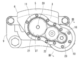
図2に示すように、運動変換機構11は、電動モータ10と平行に配置された回転軸20を有する。回転軸20には、歯車21が取り付けられている。歯車21は、回転可能に支持された中間歯車22を介して、電動モータ10のモータ軸16に取り付けられた歯車23に噛み合っており、電動モータ10で発生した回転トルクが、歯車23、中間歯車22、歯車21を順に伝達して回転軸20に入力されるようになっている。
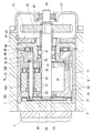
図4に示すように、運動変換機構11は、電動モータ10の回転トルクが入力される回転軸20と、この回転軸20を囲むように同軸に設けられた外輪部材24と、回転軸20に外接すると同時に外輪部材24に内接する複数の遊星ローラ25と、これらの遊星ローラ25を自転可能かつ公転可能に保持するキャリヤ26とを有する。
外輪部材24は、対向片3に形成された収容孔27内に収容され、この収容孔27の内面で軸方向に移動可能に支持されている。外輪部材24の軸方向前端には、係合凸部28が形成されている。摩擦パッド7の背面には、係合凸部28に係合する係合凹部29が形成されている。外輪部材24は、この係合凸部28と係合凹部29の係合によって回り止めされている。
図5に示すように、遊星ローラ25は、周方向に一定の間隔をおいて複数配置されている。各遊星ローラ25は、回転軸20の外周および外輪部材24の内周にそれぞれ転がり接触している。回転軸20の外周は円筒面である。回転軸20が回転したとき、遊星ローラ25は回転軸20と外輪部材24の間を自転しながら公転する。すなわち、遊星ローラ25は、回転軸20の外周から受ける回転力によって自転し、これと同時に外輪部材24の内周を転がることによって公転する。
外輪部材24の内周には、螺旋凸条30が設けられている。螺旋凸条30は、円周方向に対して斜めに延びる螺旋状の凸状である。遊星ローラ25の外周には、螺旋凸条30と係合する円周溝31が設けられている。遊星ローラ25が外輪部材24の内周を転がるとき、外輪部材24と遊星ローラ25は、螺旋凸条30と円周溝31の案内作用によって軸方向に相対移動する。この実施形態では遊星ローラ25の外周にリード角が0度の円周溝31を設けているが、円周溝31のかわりに、螺旋凸条30と異なるリード角をもつ螺旋溝を設けてもよい。
図4に示すように、キャリヤ26は、複数の遊星ローラ25の中心をそれぞれ軸方向に貫通する複数のキャリヤピン26Aと、この複数のキャリヤピン26Aのそれぞれの軸方向前端を互いに連結する環状のキャリヤプレート26Cと、複数のキャリヤピン26Aのそれぞれの軸方向後端を互いに連結する環状のキャリヤ本体26Bとからなる。各キャリヤピン26Aは、軸受32を介して遊星ローラ25を自転可能に支持している。
各キャリヤピン26Aの両端には、それぞれ縮径リングばね33が取り付けられている。縮径リングばね33は、周方向に間隔をおいて配置されたすべてのキャリヤピン26Aに外接するように装着されている。この縮径リングばね33は、各キャリヤピン26Aを半径方向内方に付勢し、その付勢力によって遊星ローラ25を回転軸20の外周に押圧し、回転軸20と遊星ローラ25の間の滑りを防止する。
キャリヤ本体26Bの内周には、滑り軸受34が取り付けられている。キャリヤ本体26Bは、この滑り軸受34を介して回転軸20で支持され、回転軸20に対して相対回転可能となっている。キャリヤ本体26Bと各遊星ローラ25の間には、遊星ローラ25を自転可能に支持するスラスト軸受35が組み込まれている。キャリヤプレート26Cとキャリヤ本体26Bは、隣り合う遊星ローラ25の間を軸方向に延びる連結棒36で連結され、この連結によって、キャリヤプレート26Cとキャリヤ本体26Bの両者が一体回転するようになっている。
荷重センサ12は、軸方向に対向する円環板状のフランジ部材40および支持部材41と、磁界を発生する磁気ターゲット42と、磁界の強さを検出する磁気センサ43とを有する。磁気ターゲット42はフランジ部材40に固定され、磁気センサ43は支持部材41に固定されている。ここで、磁気ターゲット42と磁気センサ43は、フランジ部材40に軸方向荷重が入力されたときにフランジ部材40のたわみ変形によって磁気センサ43の出力が変化するように対向配置されている。図6に示すように、磁気ターゲット42は、磁気ターゲット42と磁気センサ43の相対変位方向に対して直交する方向を磁化方向とする2個の永久磁石44,44を、一方の永久磁石44のN極と他方の永久磁石44のS極とが隣接するように配置したものである。磁気センサ43は、磁気ターゲット42を構成する2個の永久磁石44の隣り合う磁極の境目の近傍に配置されている。
キャリヤ26とフランジ部材40の間には、キャリヤ26と一体に公転する間座45と、間座45とフランジ部材40の間で軸方向荷重を伝達するスラスト軸受46とが組み込まれている。フランジ部材40の内周には、回転軸20を回転可能に支持する転がり軸受47が組み込まれている。
図4に示すように、荷重センサ12は、フランジ部材40および支持部材41の外周縁を、収容孔27の内周に装着した止め輪48,49で係止することによって軸方向の前方および後方への移動が規制されている。そして、この荷重センサ12は、間座45とスラスト軸受46を介してキャリヤ本体26Bを軸方向に支持することで、キャリヤ26の軸方向後方への移動を規制している。また、キャリヤ26は、回転軸20の軸方向前端に装着された止め輪50で軸方向前方への移動も規制されている。したがって、キャリヤ26は、軸方向前方と軸方向後方の移動がいずれも規制され、キャリヤ26に保持された遊星ローラ25も軸方向移動が規制された状態となっている。
上記の運動変換機構11は、電動モータ10から回転軸20に回転トルクが入力されたとき、遊星ローラ25がキャリヤピン26Aを中心に自転しながら回転軸20を中心に公転する。このとき螺旋凸条30と円周溝31の係合によって外輪部材24と遊星ローラ25が軸方向に相対移動するが、遊星ローラ25はキャリヤ26と共に軸方向の移動が規制されているので、遊星ローラ25は軸方向に移動せず、外輪部材24が軸方向に移動する。このように、運動変換機構11は、電動モータ10の回転トルクを外輪部材24の軸方向の直進力に変換し、その外輪部材24で摩擦パッド7をブレーキディスク2に押し付けて、ブレーキディスク2に押圧力を負荷する。このとき、外輪部材24はブレーキディスク2から摩擦パッド7を介して軸方向の反力を受け、その反力は、遊星ローラ25、キャリヤ26、間座45、スラスト軸受46を介してフランジ部材40に伝達する。そして、その反力によってフランジ部材40が軸方向後方にたわみ、磁気ターゲット42と磁気センサ43の相対位置が変化する。この相対位置の変化に応じて磁気センサ43の出力信号が変化するので、磁気センサ43の出力信号に基づいて、ブレーキディスク2に負荷される押圧力の大きさを検出することができる。
電動モータ10は、図7に示すモータ制御装置51に接続されている。モータ制御装置51は、荷重センサ12で検出される押圧力の大きさに基づいて電動モータ10の駆動電流を制御するものである。このモータ制御装置51には、ブレーキECU52から荷重指令値Fが入力され、荷重センサ12から押圧力の大きさを示す信号が入力され、位相センサ53から電動モータ10のロータ13の回転位相を示す信号が入力される。ブレーキECU52は、車両の運転者によるブレーキペダルの操作量等に基づいて各車輪の電動ブレーキ装置を制御する電子制御ユニットである。位相センサ53は、例えば、電動モータ10に電力を供給する線間電圧に基づいてロータ13の回転位相を推定する電源装置である。また、位相センサ53として、電動モータ10に組み込んだレゾルバやホール素子を採用することも可能である。
ところで、この電動ブレーキ装置は、電動モータ10に電流を印加することで、外輪部材24からブレーキディスク2に押圧力を負荷し、その後、電動モータ10に一定の電流を印加し続けることで、ブレーキディスク2に負荷される押圧力の大きさを一定に保持することができる。このときの電動モータ10の駆動電流の大きさを低減することができれば、電動モータ10の消費電力を効果的に抑えることが可能となる。
そこで、電動モータ10の消費電力を抑えるため、この電動ブレーキ装置では、押圧力をブレーキディスク2に負荷して保持するときに、運動変換機構11のヒステリシス特性を考慮して電動モータ10の駆動電流を制御することにより、電動モータ10の消費電力を抑えることを可能としている。以下具体的に説明する。
運動変換機構11は、外輪部材24からブレーキディスク2に負荷する押圧力の大きさを変化させたときにヒステリシス特性を示す。ヒステリシス特性は、電動モータ10の回転トルクが増加する過程と電動モータ10の回転トルクが減少する過程とで、外輪部材24からブレーキディスク2に負荷する押圧力の大きさが同じでも、その押圧力を負荷するときの電動モータ10の回転トルクの大きさが同じにならず、前者が後者よりも大きくなる特性である。この特性は、主に、運動変換機構11の内部の摩擦力に起因して生じる。
そして、上記のモータ制御装置51は、押圧力をブレーキディスク2に負荷して保持するときに、荷重センサ12で検出される押圧力の大きさが目標値よりも大きい所定値に到達するまで電動モータ10の回転トルクを増加させてから、荷重センサ12で検出される押圧力の大きさが目標値に到達するまで電動モータ10の回転トルクを減少させるように電動モータ10の駆動電流を制御する。
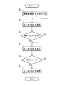
例えば、図8に示すように、モータ制御装置51は、ブレーキECU52からモータ制御装置51に荷重指令値Fが入力されたとき(ステップS1)、まず、荷重センサ12で検出される押圧力の大きさが荷重指令値Fよりも所定のオフセット値dfをもって大きく設定された値(F+df)に到達するまで電動モータ10の回転トルクを増加させ(ステップS2、S3)、続いて、荷重センサ12で検出される押圧力の大きさが荷重指令値Fに到達するまで電動モータ10の回転トルクを減少させ(ステップS4、S5)、その後、電動モータ10の回転トルクを保持するように電動モータ10の駆動電流を制御する(ステップS6)。ここで、オフセット値dfは、荷重指令値Fに比べて十分に小さく設定される微小値である。
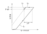
この制御により、電動モータ10の消費電力を低減することが可能となる。すなわち、図10に示すように、電動モータ10の回転トルクをゼロから増加させると、正効率を示す直線L1に沿って押圧力が上昇する。その後、電動モータ10の回転トルクが減少に転じると、直線L2に沿って状態が推移し、直線L3に到達するまで押圧力の大きさがほとんど変化しない非線形のヒステリシス特性を示す。更に、電動モータ10の回転トルクを減少させると、逆効率を示す直線L3に沿って押圧力が減少する。ここで、電動モータ10の回転トルクが減少する過程L3で押圧力が荷重指令値Fに到達したときと、電動モータ10の回転トルクが増加する過程L1で押圧力が荷重指令値Fに到達したときとで、荷重指令値Fの大きさが同じでも、押圧力が荷重指令値Fに到達したときの電動モータ10の回転トルクの大きさが同じにならず、前者が後者よりもΔTの分小さくなる(運動変換機構11のヒステリシス特性)。そのため、電動モータ10の回転トルクが減少する過程L3で押圧力が荷重指令値Fに到達するように制御を行なうことで、押圧力が荷重指令値F(目標値)に到達したときの電動モータ10の回転トルクが抑えられ、その後、押圧力を保持するために要する電動モータ10の消費電力を低減することができる。
ここで、モータ制御装置51は、荷重センサ12で検出される押圧力を荷重指令値Fに保持するとき、ロータ13に生じるトルクが最大となる回転位相のうち、押圧力が荷重指令値Fに一致するときの位相に最も近い回転位相でロータ13が停止するように電動モータ10の駆動電流を制御すると好ましい。すなわち、荷重センサ12で検出される押圧力の大きさが荷重指令値Fに到達するまで電動モータ10の回転トルクを減少させるときに、荷重センサ12で検出される押圧力が荷重指令値Fに完全に一致するときの回転位相でロータ13を停止させるのではなく、ロータ13がステータ14に対して1回転する間にロータ13に生じるトルクが最大となる回転位相のうち、押圧力が荷重指令値Fに一致するときの位相に最も近い回転位相でロータ13が停止するように電動モータ10の駆動電流を制御する。これにより、ブレーキディスク2に押圧力を負荷した後、その押圧力の大きさを安定して保持することが可能となる。
トルクが最大となる回転位相でロータ13を停止させる上記制御は、荷重指令値Fがあらかじめ設定されたしきい値よりも大きいときにのみ行なうようにすることができる。これにより、荷重指令値Fが比較的小さいときにも、安定した押圧力を得ることができる。
また、例えば、図9に示すように、モータ制御装置51は、ブレーキECU52からモータ制御装置51に荷重指令値Fが入力されたとき(ステップS1)、まず、荷重センサ12で検出される押圧力の大きさが荷重指令値Fに到達するまで電動モータ10の回転トルクを増加させ(ステップS2、S3)、続いて、荷重センサ12で検出される押圧力の大きさが荷重指令値Fよりも所定のオフセット値dfをもって小さく設定された値(F-df)に到達するまで電動モータ10の回転トルクを減少させ(ステップS4、S5)、その後、電動モータ10の回転トルクを保持するように電動モータ10の駆動電流を制御するようにしてもよい(ステップS6)。
このように電動モータ10の駆動電流を制御しても、図11に示すように、電動モータ10の回転トルクが減少する過程L3で押圧力が目標値(F-df)に到達したときと、電動モータ10の回転トルクが増加する過程L1で押圧力が目標値(F-df)に到達したときとで、目標値(F-df)の大きさが同じでも、押圧力が目標値(F-df)に到達したときの電動モータ10の回転トルクの大きさが同じにならず、前者が後者よりもΔTの分小さくなる(運動変換機構11のヒステリシス特性)。そのため、上述のように、電動モータ10の回転トルクが減少する過程L3で押圧力が目標値(F-df)に到達するように制御を行なうことで、押圧力が目標値(F-df)に到達したときの電動モータ10の回転トルクが抑えられ、その後、押圧力を保持するために要する電動モータ10の消費電力を低減することができる。
ここでも、モータ制御装置51は、荷重センサ12で検出される押圧力を荷重指令値Fよりも所定のオフセット値dfをもって小さく設定された目標値に保持するとき、ロータ13に生じるトルクが最大となる回転位相のうち、押圧力が目標値(F-df)に一致するときの位相に最も近い回転位相でロータ13が停止するように電動モータ10の駆動電流を制御すると好ましい。これにより、ブレーキディスク2に押圧力を負荷した後、その押圧力の大きさを安定して保持することが可能となる。
また、トルクが最大となる回転位相でロータ13を停止させる上記制御は、押圧力の目標値(F-df)があらかじめ設定されたしきい値よりも大きいときにのみ行なうようにすることができる。これにより、押圧力の目標値が比較的小さいときにも、安定した押圧力を得ることができる。
上述の電動ブレーキ装置は、ブレーキディスク2に押圧力を負荷し、その押圧力を目標値に保持するときに、電動モータ10の回転トルクが減少する過程L3で押圧力が目標値に到達するように電動モータ10の駆動電流を制御するので、電動モータ10の回転トルクが増加する過程L1で押圧力を目標値に到達させる通常の制御と比較して、押圧力が目標値に到達したときの電動モータ10の回転トルクが小さい。そのため、押圧力を目標値に保持するときの電動モータ10の駆動電流を抑制することができ、電動モータ10の消費電力が低い。
また、上記実施形態では、電動モータ10の回転トルクを直動部材の直進力に変換する運動変換機構11として、電動モータ10の回転トルクが入力される回転軸20と、この回転軸20の外周の円筒面に転がり接触する複数の遊星ローラ25と、これらの複数の遊星ローラ25を囲むように配置された外輪部材24と、その外輪部材24の内周に設けられた螺旋凸条30と、その螺旋凸条30と係合するように各遊星ローラ25の外周に設けられた螺旋溝または円周溝31とを有する遊星ローラ機構を採用している。このようにすると、遊星ローラ機構は、回転軸20を1回転させたときに生じる直動部材(ここでは外輪部材24)の軸方向の移動量が小さく、減速機構の機能を有するため、ヒステリシス特性を顕著に示す。そのため、遊星ローラ機構を用いた電動ブレーキ装置に上記制御を適用することにより、電動モータ10の消費電力を効果的に低減することができる。
上記モータ制御装置51は、所定の時間毎に、電動モータ10で発生する回転トルクを増加させた後に減少させる動作を実行するように電動モータ10の駆動電流を制御することができる。そして、このとき荷重センサ12で検出される押圧力の大きさと電動モータ10の駆動電流の大きさとの対応関係に基づいて、電動モータ10で発生する回転トルクが増加するときの電動モータ10の駆動電流とそのときブレーキディスク2に負荷される押圧力との対応関係(正効率)と、電動モータ10で発生する回転トルクが減少するときの電動モータ10の駆動電流とそのときブレーキディスク2に負荷される押圧力との対応関係(逆効率)とを推定し、それを記憶することができる。更に、この記憶した両対応関係に基づいて電動モータ10の駆動電流を制御するように構成することができる。正効率と逆効率を推定して記憶する動作は、モータ制御装置51に電源が投入された直後に行なってもよい。
上記実施形態では、電動モータ10の回転トルクを直動部材(外輪部材24)の直進力に変換する運動変換機構11として、遊星ローラ機構を採用した電動式直動アクチュエータを例に挙げて説明したが、この発明は、他の構成の運動変換機構11(例えば、滑りねじ機構、ボールねじ機構、ボールランプ機構など)を採用した電動式直動アクチュエータにも同様に適用することができる。特に、運動変換機構11として、上述の遊星ローラ機構や後述の滑りねじ機構を採用すると、電動モータ10の消費電力を効果的に低減することが可能である。
運動変換機構11として滑りねじ機構を採用した電動式直動アクチュエータの例を図12に示す。以下、上記実施形態に対応する部分は、同一の符号を付して説明を省略する。
図12の電動式直動アクチュエータは、電動モータ10の回転トルクが入力される回転軸61と、回転軸61と一体に回転するねじ軸62と、ねじ軸62にねじ係合するナット63と、ナット63の軸方向後方に配置された荷重センサ12とを有する。ねじ軸62は、雄ねじ64を外周に形成した軸体であり、ナット63は、雌ねじ65を内周に形成した筒体である。雄ねじ64と雌ねじ65は互いに摩擦接触している。雄ねじ64および雌ねじ65は、例えば、ねじ山の断面形状が台形の台形ねじを採用することができる。
ナット63は、キャリパボディ6の対向片3に設けられた収容孔27内に、キャリパボディ6に対して回り止めされた状態で軸方向にスライド可能に収容されている。ねじ軸62の軸方向後端にはねじ軸62と一体に回転する間座45が設けられ、その間座45がスラスト軸受46を介して荷重センサ12で支持されている。ここで、荷重センサ12は、間座45とスラスト軸受46とねじ軸62とを介してナット63を軸方向に支持することで、ナット63の軸方向後方への移動を規制している。
この電動式直動アクチュエータは、電動モータ10の回転トルクを回転軸61に入力することによって、ねじ軸62とナット63を相対回転させて、ナット63を軸方向前方に移動させ、そのナット63で摩擦パッド7をブレーキディスク2に押圧することで、制動力を発生させる。このとき、直動部材としてのナット63は、軸方向後方への反力を受け、その反力は、ねじ軸62、間座45、スラスト軸受46を介して荷重センサ12に伝達する。
この滑りねじ機構を運動変換機構11として採用した電動ブレーキ装置も、押圧力をブレーキディスク2に負荷して保持するときに、荷重センサ12で検出される押圧力の大きさが目標値よりも大きい所定値に到達するまで電動モータ10の回転トルクを増加させてから、荷重センサ12で検出される押圧力の大きさが目標値に到達するまで電動モータ10の回転トルクを減少させるように電動モータ10の駆動電流を制御することで、押圧力を目標値に保持するときの電動モータ10の駆動電流を抑制することができ、電動モータ10の消費電力を低減することができる。
2 ブレーキディスク
7 摩擦パッド
10 電動モータ
11 運動変換機構
12 荷重センサ
13 ロータ
14 ステータ
20 回転軸
24 外輪部材
25 遊星ローラ
26 キャリヤ
30 螺旋凸条
31 円周溝
51 モータ制御装置
52 ブレーキECU
53 位相センサ
7 摩擦パッド
10 電動モータ
11 運動変換機構
12 荷重センサ
13 ロータ
14 ステータ
20 回転軸
24 外輪部材
25 遊星ローラ
26 キャリヤ
30 螺旋凸条
31 円周溝
51 モータ制御装置
52 ブレーキECU
53 位相センサ
Claims (7)
- 駆動電流に応じた大きさの回転トルクを発生する電動モータ(10)と、
その電動モータ(10)の回転トルクを直動部材(24)の直進力に変換し、その直動部材(24)で対象物(2)に押圧力を負荷する運動変換機構(11)と、
前記対象物(2)に負荷される押圧力の大きさを検出する荷重センサ(12)と、
その荷重センサ(12)で検出される押圧力の大きさに基づいて前記電動モータ(10)の駆動電流を制御するモータ制御装置(51)とを有し、
前記運動変換機構(11)は、前記電動モータ(10)の回転トルクが増加する過程(L1)と前記電動モータ(10)の回転トルクが減少する過程(L3)とで、前記直動部材(24)から対象物(2)に負荷する押圧力の大きさが同じでも、その押圧力を負荷するときの電動モータ(10)の回転トルクの大きさが同じにならず、前者が後者よりも大きくなるヒステリシス特性を示すものを採用し、
前記モータ制御装置(51)は、押圧力を対象物(2)に負荷して保持するときに、前記荷重センサ(12)で検出される押圧力の大きさが目標値よりも大きい所定値に到達するまで電動モータ(10)の回転トルクを増加させてから、荷重センサ(12)で検出される押圧力の大きさが目標値に到達するまで電動モータ(10)の回転トルクを減少させるように前記電動モータ(10)の駆動電流を制御する電動式直動アクチュエータ。 - 前記目標値は、前記モータ制御装置(51)に外部(52)から入力される荷重指令値(F)であり、前記所定値は、前記荷重指令値(F)よりも所定のオフセット値(df)をもって大きく設定された値である請求項1に記載の電動式直動アクチュエータ。
- 前記目標値は、前記モータ制御装置(51)に外部(52)から入力される荷重指令値(F)よりも所定のオフセット値(df)をもって小さく設定された値であり、前記所定値は、前記荷重指令値(F)である請求項1に記載の電動式直動アクチュエータ。
- 前記電動モータ(10)は、回転可能に支持されたロータ(13)と、このロータ(13)に回転トルクを生じさせるステータ(14)とを有し、そのロータ(13)およびステータ(14)は、ロータ(13)がステータ(14)に対して1回転する間に、ロータ(13)に生じる回転トルクが最大となる回転位相と、ロータ(13)に生じる回転トルクが最小となる回転位相とが交互にあらわれるように構成され、
前記ロータ(13)の回転位相を検出する位相センサ(53)を設け、
前記モータ制御装置(51)は、前記荷重センサ(12)で検出される押圧力を目標値に保持するとき、前記ロータ(13)に生じるトルクが最大となる回転位相のうち、前記押圧力が目標値に一致するときの位相に最も近い回転位相でロータ(13)が停止するように電動モータ(10)の駆動電流を制御する請求項1から3のいずれかに記載の電動式直動アクチュエータ。 - 前記モータ制御装置(51)は、前記押圧力の目標値があらかじめ設定されたしきい値よりも大きいときにのみ請求項4に記載の制御を行なう請求項4に記載の電動式直動アクチュエータ。
- 前記運動変換機構(11)は、前記電動モータ(10)の回転トルクが入力される回転軸(20)と、この回転軸(20)を囲むように同軸に設けられた外輪部材(24)と、前記回転軸(20)に外接すると同時に前記外輪部材(24)に内接する複数の遊星ローラ(25)と、これらの遊星ローラ(25)を自転可能かつ公転可能に保持するキャリヤ(26)と、前記外輪部材(24)の内周に設けられた螺旋凸条(30)と、その螺旋凸条(30)と係合するように各遊星ローラ(25)の外周に設けられた螺旋溝または円周溝(31)とを有する遊星ローラ機構である請求項1から5のいずれかに記載の電動式直動アクチュエータ。
- 前記対象物が、車輪と一体に回転するブレーキディスク(2)であり、このブレーキディスク(2)に摩擦パッド(7)を押し付けるアクチュエータとして請求項1から6のいずれかに記載の電動式直動アクチュエータを用いた電動ブレーキ装置。
Priority Applications (3)
| Application Number | Priority Date | Filing Date | Title |
|---|---|---|---|
| EP14798431.4A EP2999111B1 (en) | 2013-05-17 | 2014-05-02 | Electric linear actuator and electric brake device |
| CN201480028722.6A CN105228873B (zh) | 2013-05-17 | 2014-05-02 | 电动式直动致动器以及电动制动装置 |
| US14/889,872 US9797462B2 (en) | 2013-05-17 | 2014-05-02 | Electric linear motion actuator and electric brake system |
Applications Claiming Priority (2)
| Application Number | Priority Date | Filing Date | Title |
|---|---|---|---|
| JP2013-105153 | 2013-05-17 | ||
| JP2013105153A JP6080682B2 (ja) | 2013-05-17 | 2013-05-17 | 電動式直動アクチュエータおよび電動ブレーキ装置 |
Publications (1)
| Publication Number | Publication Date |
|---|---|
| WO2014185292A1 true WO2014185292A1 (ja) | 2014-11-20 |
Family
ID=51898271
Family Applications (1)
| Application Number | Title | Priority Date | Filing Date |
|---|---|---|---|
| PCT/JP2014/062153 Ceased WO2014185292A1 (ja) | 2013-05-17 | 2014-05-02 | 電動式直動アクチュエータおよび電動ブレーキ装置 |
Country Status (5)
| Country | Link |
|---|---|
| US (1) | US9797462B2 (ja) |
| EP (1) | EP2999111B1 (ja) |
| JP (1) | JP6080682B2 (ja) |
| CN (2) | CN108177642B (ja) |
| WO (1) | WO2014185292A1 (ja) |
Families Citing this family (21)
| Publication number | Priority date | Publication date | Assignee | Title |
|---|---|---|---|---|
| JP6352202B2 (ja) * | 2015-02-16 | 2018-07-04 | 株式会社ミツバ | ブレーキ用アクチュエータおよびブレーキ装置 |
| FR3045754B1 (fr) * | 2015-12-17 | 2019-06-14 | Foundation Brakes France | Actionneur electromecanique a encombrement reduit pour frein a disque |
| EP3473891A4 (en) * | 2016-06-16 | 2019-06-19 | NTN Corporation | ELECTRICAL LINEAR ACTUATOR AND ELECTRIC BRAKING DEVICE |
| JP2018002105A (ja) * | 2016-07-08 | 2018-01-11 | Ntn株式会社 | 電動式直動アクチュエータ |
| JP6752668B2 (ja) * | 2016-09-28 | 2020-09-09 | Ntn株式会社 | 電動ブレーキ装置 |
| JP2018070083A (ja) * | 2016-11-04 | 2018-05-10 | Ntn株式会社 | 電動ブレーキ装置 |
| JP6506236B2 (ja) * | 2016-11-28 | 2019-04-24 | トヨタ自動車株式会社 | 電動ブレーキ制御装置 |
| US10975940B2 (en) * | 2017-08-24 | 2021-04-13 | Eaton Intelligent Power Limited | Actuator and method |
| JP6900881B2 (ja) * | 2017-11-20 | 2021-07-07 | トヨタ自動車株式会社 | 電動ブレーキ制御装置 |
| DE102018210511A1 (de) * | 2018-06-27 | 2020-01-02 | Robert Bosch Gmbh | Verfahren zur Ermittlung der Bremskraft in einer elektromechanischen Bremsvorrichtung mit einem elektrischen Bremsmotor |
| JP7115934B2 (ja) | 2018-08-21 | 2022-08-09 | 株式会社デンソー | モータ装置 |
| US10876587B2 (en) * | 2019-03-28 | 2020-12-29 | Keyang Electric Machinery Co., Ltd. | Actuator assembly with integrated housing for electromechanical parking brake |
| JP7201807B2 (ja) * | 2019-06-27 | 2023-01-10 | アルプスアルパイン株式会社 | 操作装置 |
| CN111002966B (zh) * | 2019-12-24 | 2021-06-04 | 精诚工科汽车系统有限公司 | 车辆制动控制方法、装置及线控助力制动系统 |
| CN112810586A (zh) * | 2021-01-20 | 2021-05-18 | 清华大学 | 一种商用车制动器促动模组及制动系统 |
| JP7800336B2 (ja) * | 2022-08-01 | 2026-01-16 | 株式会社デンソー | 車両用制動装置 |
| JP7779217B2 (ja) * | 2022-09-01 | 2025-12-03 | 株式会社デンソー | 車両用制動装置 |
| JP7797988B2 (ja) * | 2022-09-01 | 2026-01-14 | 株式会社デンソー | 車両用制動装置 |
| JP7835139B2 (ja) * | 2022-09-22 | 2026-03-25 | 株式会社デンソー | 車両用制動装置 |
| US20250010835A1 (en) * | 2023-07-06 | 2025-01-09 | ZF Active Safety US Inc. | Electromechanical brake having a force sensor |
| JP2025075722A (ja) * | 2023-10-31 | 2025-05-15 | 株式会社アドヴィックス | 電動制動装置 |
Citations (7)
| Publication number | Priority date | Publication date | Assignee | Title |
|---|---|---|---|---|
| JPH06344875A (ja) * | 1993-05-28 | 1994-12-20 | Wabco Vermoegensverwaltung Gmbh | 制動値を目標制動値に調整するための方法 |
| JP2000016279A (ja) * | 1998-06-30 | 2000-01-18 | Tokico Ltd | 電動ブレーキ装置 |
| JP2002104169A (ja) * | 2000-09-28 | 2002-04-10 | Denso Corp | 車両用ブレーキ装置 |
| JP2003522060A (ja) * | 1997-09-29 | 2003-07-22 | コンティネンタル・テーベス・アクチエンゲゼルシヤフト・ウント・コンパニー・オッフェネ・ハンデルスゲゼルシヤフト | 所定の操作力を加える方法 |
| JP2009220807A (ja) * | 2008-02-22 | 2009-10-01 | Hitachi Ltd | 自動車ブレーキ用モータ駆動装置 |
| JP2011241851A (ja) | 2010-05-14 | 2011-12-01 | Ntn Corp | 電動式直動アクチュエータおよび電動式ブレーキ装置 |
| JP2013083550A (ja) * | 2011-10-11 | 2013-05-09 | Ntn Corp | 直動アクチュエータ用の磁気式荷重センサおよび直動アクチュエータ |
Family Cites Families (15)
| Publication number | Priority date | Publication date | Assignee | Title |
|---|---|---|---|---|
| US4995483A (en) * | 1989-12-18 | 1991-02-26 | Aircraft Braking Systems Corporation | Motor position feedback controlled electrically actuated aircraft brake |
| JP2004122838A (ja) * | 2002-08-07 | 2004-04-22 | Asmo Co Ltd | 電動駐車ブレーキ装置及び電動駐車ブレーキ装置の制御方法 |
| JP2004175203A (ja) * | 2002-11-27 | 2004-06-24 | Advics:Kk | 電動パーキングブレーキ装置 |
| US7104616B2 (en) * | 2003-07-02 | 2006-09-12 | Goodrich Corporation | Brake gain-based torque controller |
| JP2005067400A (ja) * | 2003-08-25 | 2005-03-17 | Advics:Kk | 電気ブレーキシステム |
| JP4342469B2 (ja) * | 2005-04-01 | 2009-10-14 | トヨタ自動車株式会社 | 車両用ブレーキの制御装置 |
| JP2008049800A (ja) * | 2006-08-24 | 2008-03-06 | Hitachi Ltd | 電動ブレーキ装置およびその制御方法 |
| JP4265633B2 (ja) * | 2006-09-15 | 2009-05-20 | トヨタ自動車株式会社 | 電動パーキングブレーキシステム |
| JP2009029294A (ja) * | 2007-07-27 | 2009-02-12 | Hitachi Ltd | 車両用ブレーキシステム |
| EP2214944B1 (de) * | 2007-10-24 | 2011-08-31 | Continental Teves AG & Co. oHG | Feststellbremse und verfahren zum betreiben derselben |
| US20090281702A1 (en) * | 2008-05-08 | 2009-11-12 | Cahill Eric D | Resolving stack closure of a position controlled electric brake system |
| EP2484935B1 (en) * | 2009-09-29 | 2019-11-06 | NTN Corporation | Electric linear motion actuator and electric disc brake assembly |
| JP5406155B2 (ja) * | 2010-10-06 | 2014-02-05 | 日立オートモティブシステムズ株式会社 | ディスクブレーキ装置 |
| JP6182314B2 (ja) * | 2013-01-08 | 2017-08-16 | Ntn株式会社 | 電動ブレーキ装置 |
| DE112014001471B4 (de) * | 2013-03-15 | 2022-02-17 | Advics Co., Ltd. | Elektrisches Bremssystem für ein Fahrzeug |
-
2013
- 2013-05-17 JP JP2013105153A patent/JP6080682B2/ja active Active
-
2014
- 2014-05-02 EP EP14798431.4A patent/EP2999111B1/en active Active
- 2014-05-02 US US14/889,872 patent/US9797462B2/en not_active Expired - Fee Related
- 2014-05-02 WO PCT/JP2014/062153 patent/WO2014185292A1/ja not_active Ceased
- 2014-05-02 CN CN201711392653.9A patent/CN108177642B/zh not_active Expired - Fee Related
- 2014-05-02 CN CN201480028722.6A patent/CN105228873B/zh not_active Expired - Fee Related
Patent Citations (7)
| Publication number | Priority date | Publication date | Assignee | Title |
|---|---|---|---|---|
| JPH06344875A (ja) * | 1993-05-28 | 1994-12-20 | Wabco Vermoegensverwaltung Gmbh | 制動値を目標制動値に調整するための方法 |
| JP2003522060A (ja) * | 1997-09-29 | 2003-07-22 | コンティネンタル・テーベス・アクチエンゲゼルシヤフト・ウント・コンパニー・オッフェネ・ハンデルスゲゼルシヤフト | 所定の操作力を加える方法 |
| JP2000016279A (ja) * | 1998-06-30 | 2000-01-18 | Tokico Ltd | 電動ブレーキ装置 |
| JP2002104169A (ja) * | 2000-09-28 | 2002-04-10 | Denso Corp | 車両用ブレーキ装置 |
| JP2009220807A (ja) * | 2008-02-22 | 2009-10-01 | Hitachi Ltd | 自動車ブレーキ用モータ駆動装置 |
| JP2011241851A (ja) | 2010-05-14 | 2011-12-01 | Ntn Corp | 電動式直動アクチュエータおよび電動式ブレーキ装置 |
| JP2013083550A (ja) * | 2011-10-11 | 2013-05-09 | Ntn Corp | 直動アクチュエータ用の磁気式荷重センサおよび直動アクチュエータ |
Also Published As
| Publication number | Publication date |
|---|---|
| US9797462B2 (en) | 2017-10-24 |
| JP2014226007A (ja) | 2014-12-04 |
| EP2999111A1 (en) | 2016-03-23 |
| CN108177642B (zh) | 2020-08-11 |
| EP2999111A4 (en) | 2016-08-31 |
| US20160091039A1 (en) | 2016-03-31 |
| CN105228873A (zh) | 2016-01-06 |
| JP6080682B2 (ja) | 2017-02-15 |
| CN105228873B (zh) | 2018-01-26 |
| EP2999111B1 (en) | 2019-11-06 |
| CN108177642A (zh) | 2018-06-19 |
Similar Documents
| Publication | Publication Date | Title |
|---|---|---|
| JP6080682B2 (ja) | 電動式直動アクチュエータおよび電動ブレーキ装置 | |
| JP6076059B2 (ja) | 車両用電動ブレーキ装置 | |
| US10479342B2 (en) | Electrically powered brake device | |
| JP5977016B2 (ja) | 電動式直動アクチュエータおよび電動ブレーキ装置 | |
| EP2907709B1 (en) | Electric-powered parking brake device | |
| JP6258531B2 (ja) | 電動式直動アクチュエータおよび電動ブレーキ装置 | |
| JP5613412B2 (ja) | 渦電流式減速装置 | |
| EP2775170B1 (en) | Electric linear motion actuator | |
| JP2016217415A (ja) | パーキング機能付き電動ブレーキ装置 | |
| JP6779673B2 (ja) | 電動式直動アクチュエータ | |
| JP2005133863A (ja) | 制動装置 | |
| JP2006070962A (ja) | 電動駐車ブレーキ装置 | |
| JP2014088911A (ja) | 電動式直動アクチュエータ | |
| JP6739262B2 (ja) | 電動式直動アクチュエータおよび電動ブレーキ装置 | |
| JP2021059239A (ja) | 電動ブレーキ | |
| JP2020090166A (ja) | アクチュエータ制御装置 |
Legal Events
| Date | Code | Title | Description |
|---|---|---|---|
| WWE | Wipo information: entry into national phase |
Ref document number: 201480028722.6 Country of ref document: CN |
|
| 121 | Ep: the epo has been informed by wipo that ep was designated in this application |
Ref document number: 14798431 Country of ref document: EP Kind code of ref document: A1 |
|
| WWE | Wipo information: entry into national phase |
Ref document number: 14889872 Country of ref document: US |
|
| NENP | Non-entry into the national phase |
Ref country code: DE |
|
| WWE | Wipo information: entry into national phase |
Ref document number: 2014798431 Country of ref document: EP |