WO2014189250A2 - 동물들의 코무늬를 이용한 동물 개체 인식 장치 및 방법 - Google Patents
동물들의 코무늬를 이용한 동물 개체 인식 장치 및 방법 Download PDFInfo
- Publication number
- WO2014189250A2 WO2014189250A2 PCT/KR2014/004487 KR2014004487W WO2014189250A2 WO 2014189250 A2 WO2014189250 A2 WO 2014189250A2 KR 2014004487 W KR2014004487 W KR 2014004487W WO 2014189250 A2 WO2014189250 A2 WO 2014189250A2
- Authority
- WO
- WIPO (PCT)
- Prior art keywords
- animal
- unit
- image
- nose pattern
- nose
- Prior art date
- Legal status (The legal status is an assumption and is not a legal conclusion. Google has not performed a legal analysis and makes no representation as to the accuracy of the status listed.)
- Ceased
Links
Images






Classifications
-
- A—HUMAN NECESSITIES
- A01—AGRICULTURE; FORESTRY; ANIMAL HUSBANDRY; HUNTING; TRAPPING; FISHING
- A01K—ANIMAL HUSBANDRY; AVICULTURE; APICULTURE; PISCICULTURE; FISHING; REARING OR BREEDING ANIMALS, NOT OTHERWISE PROVIDED FOR; NEW BREEDS OF ANIMALS
- A01K11/00—Marking of animals
- A01K11/006—Automatic identification systems for animals, e.g. electronic devices, transponders for animals
-
- A—HUMAN NECESSITIES
- A01—AGRICULTURE; FORESTRY; ANIMAL HUSBANDRY; HUNTING; TRAPPING; FISHING
- A01K—ANIMAL HUSBANDRY; AVICULTURE; APICULTURE; PISCICULTURE; FISHING; REARING OR BREEDING ANIMALS, NOT OTHERWISE PROVIDED FOR; NEW BREEDS OF ANIMALS
- A01K15/00—Devices for taming animals, e.g. nose-rings or hobbles; Devices for overturning animals in general; Training or exercising equipment; Covering boxes
- A01K15/04—Devices for impeding movement; Devices for impeding passage through fencing, e.g. hobbles or the like; Anti-kicking devices
-
- A—HUMAN NECESSITIES
- A01—AGRICULTURE; FORESTRY; ANIMAL HUSBANDRY; HUNTING; TRAPPING; FISHING
- A01K—ANIMAL HUSBANDRY; AVICULTURE; APICULTURE; PISCICULTURE; FISHING; REARING OR BREEDING ANIMALS, NOT OTHERWISE PROVIDED FOR; NEW BREEDS OF ANIMALS
- A01K29/00—Other apparatus for animal husbandry
-
- A—HUMAN NECESSITIES
- A61—MEDICAL OR VETERINARY SCIENCE; HYGIENE
- A61B—DIAGNOSIS; SURGERY; IDENTIFICATION
- A61B5/00—Measuring for diagnostic purposes; Identification of persons
- A61B5/0059—Measuring for diagnostic purposes; Identification of persons using light, e.g. diagnosis by transillumination, diascopy, fluorescence
- A61B5/0077—Devices for viewing the surface of the body, e.g. camera, magnifying lens
-
- A—HUMAN NECESSITIES
- A61—MEDICAL OR VETERINARY SCIENCE; HYGIENE
- A61B—DIAGNOSIS; SURGERY; IDENTIFICATION
- A61B5/00—Measuring for diagnostic purposes; Identification of persons
- A61B5/68—Arrangements of detecting, measuring or recording means, e.g. sensors, in relation to patient
- A61B5/6801—Arrangements of detecting, measuring or recording means, e.g. sensors, in relation to patient specially adapted to be attached to or worn on the body surface
- A61B5/6813—Specially adapted to be attached to a specific body part
- A61B5/6814—Head
- A61B5/6819—Nose
-
- A—HUMAN NECESSITIES
- A61—MEDICAL OR VETERINARY SCIENCE; HYGIENE
- A61B—DIAGNOSIS; SURGERY; IDENTIFICATION
- A61B5/00—Measuring for diagnostic purposes; Identification of persons
- A61B5/70—Means for positioning the patient in relation to the detecting, measuring or recording means
- A61B5/702—Posture restraints
-
- G—PHYSICS
- G06—COMPUTING OR CALCULATING; COUNTING
- G06F—ELECTRIC DIGITAL DATA PROCESSING
- G06F18/00—Pattern recognition
- G06F18/20—Analysing
- G06F18/22—Matching criteria, e.g. proximity measures
-
- G—PHYSICS
- G06—COMPUTING OR CALCULATING; COUNTING
- G06T—IMAGE DATA PROCESSING OR GENERATION, IN GENERAL
- G06T7/00—Image analysis
- G06T7/0002—Inspection of images, e.g. flaw detection
- G06T7/0012—Biomedical image inspection
-
- G—PHYSICS
- G06—COMPUTING OR CALCULATING; COUNTING
- G06T—IMAGE DATA PROCESSING OR GENERATION, IN GENERAL
- G06T7/00—Image analysis
- G06T7/10—Segmentation; Edge detection
- G06T7/11—Region-based segmentation
-
- G—PHYSICS
- G06—COMPUTING OR CALCULATING; COUNTING
- G06V—IMAGE OR VIDEO RECOGNITION OR UNDERSTANDING
- G06V10/00—Arrangements for image or video recognition or understanding
- G06V10/40—Extraction of image or video features
-
- G—PHYSICS
- G06—COMPUTING OR CALCULATING; COUNTING
- G06V—IMAGE OR VIDEO RECOGNITION OR UNDERSTANDING
- G06V10/00—Arrangements for image or video recognition or understanding
- G06V10/70—Arrangements for image or video recognition or understanding using pattern recognition or machine learning
- G06V10/74—Image or video pattern matching; Proximity measures in feature spaces
- G06V10/75—Organisation of the matching processes, e.g. simultaneous or sequential comparisons of image or video features; Coarse-fine approaches, e.g. multi-scale approaches; using context analysis; Selection of dictionaries
-
- G—PHYSICS
- G06—COMPUTING OR CALCULATING; COUNTING
- G06V—IMAGE OR VIDEO RECOGNITION OR UNDERSTANDING
- G06V10/00—Arrangements for image or video recognition or understanding
- G06V10/88—Image or video recognition using optical means, e.g. reference filters, holographic masks, frequency domain filters or spatial domain filters
-
- G—PHYSICS
- G06—COMPUTING OR CALCULATING; COUNTING
- G06V—IMAGE OR VIDEO RECOGNITION OR UNDERSTANDING
- G06V40/00—Recognition of biometric, human-related or animal-related patterns in image or video data
- G06V40/10—Human or animal bodies, e.g. vehicle occupants or pedestrians; Body parts, e.g. hands
- G06V40/16—Human faces, e.g. facial parts, sketches or expressions
- G06V40/168—Feature extraction; Face representation
- G06V40/171—Local features and components; Facial parts ; Occluding parts, e.g. glasses; Geometrical relationships
-
- G—PHYSICS
- G06—COMPUTING OR CALCULATING; COUNTING
- G06V—IMAGE OR VIDEO RECOGNITION OR UNDERSTANDING
- G06V40/00—Recognition of biometric, human-related or animal-related patterns in image or video data
- G06V40/10—Human or animal bodies, e.g. vehicle occupants or pedestrians; Body parts, e.g. hands
- G06V40/16—Human faces, e.g. facial parts, sketches or expressions
- G06V40/172—Classification, e.g. identification
-
- A—HUMAN NECESSITIES
- A61—MEDICAL OR VETERINARY SCIENCE; HYGIENE
- A61B—DIAGNOSIS; SURGERY; IDENTIFICATION
- A61B2503/00—Evaluating a particular growth phase or type of persons or animals
- A61B2503/40—Animals
-
- A—HUMAN NECESSITIES
- A61—MEDICAL OR VETERINARY SCIENCE; HYGIENE
- A61B—DIAGNOSIS; SURGERY; IDENTIFICATION
- A61B2562/00—Details of sensors; Constructional details of sensor housings or probes; Accessories for sensors
- A61B2562/02—Details of sensors specially adapted for in-vivo measurements
- A61B2562/0233—Special features of optical sensors or probes classified in A61B5/00
- A61B2562/0242—Special features of optical sensors or probes classified in A61B5/00 for varying or adjusting the optical path length in the tissue
-
- A—HUMAN NECESSITIES
- A61—MEDICAL OR VETERINARY SCIENCE; HYGIENE
- A61B—DIAGNOSIS; SURGERY; IDENTIFICATION
- A61B2576/00—Medical imaging apparatus involving image processing or analysis
-
- A—HUMAN NECESSITIES
- A61—MEDICAL OR VETERINARY SCIENCE; HYGIENE
- A61B—DIAGNOSIS; SURGERY; IDENTIFICATION
- A61B5/00—Measuring for diagnostic purposes; Identification of persons
- A61B5/0059—Measuring for diagnostic purposes; Identification of persons using light, e.g. diagnosis by transillumination, diascopy, fluorescence
-
- A—HUMAN NECESSITIES
- A61—MEDICAL OR VETERINARY SCIENCE; HYGIENE
- A61B—DIAGNOSIS; SURGERY; IDENTIFICATION
- A61B5/00—Measuring for diagnostic purposes; Identification of persons
- A61B5/117—Identification of persons
- A61B5/1171—Identification of persons based on the shapes or appearances of their bodies or parts thereof
- A61B5/1176—Recognition of faces
-
- A—HUMAN NECESSITIES
- A61—MEDICAL OR VETERINARY SCIENCE; HYGIENE
- A61B—DIAGNOSIS; SURGERY; IDENTIFICATION
- A61B5/00—Measuring for diagnostic purposes; Identification of persons
- A61B5/72—Signal processing specially adapted for physiological signals or for diagnostic purposes
- A61B5/7235—Details of waveform analysis
- A61B5/7253—Details of waveform analysis characterised by using transforms
- A61B5/7257—Details of waveform analysis characterised by using transforms using Fourier transforms
-
- A—HUMAN NECESSITIES
- A61—MEDICAL OR VETERINARY SCIENCE; HYGIENE
- A61B—DIAGNOSIS; SURGERY; IDENTIFICATION
- A61B5/00—Measuring for diagnostic purposes; Identification of persons
- A61B5/72—Signal processing specially adapted for physiological signals or for diagnostic purposes
- A61B5/7235—Details of waveform analysis
- A61B5/7253—Details of waveform analysis characterised by using transforms
- A61B5/726—Details of waveform analysis characterised by using transforms using Wavelet transforms
-
- G—PHYSICS
- G06—COMPUTING OR CALCULATING; COUNTING
- G06V—IMAGE OR VIDEO RECOGNITION OR UNDERSTANDING
- G06V40/00—Recognition of biometric, human-related or animal-related patterns in image or video data
- G06V40/10—Human or animal bodies, e.g. vehicle occupants or pedestrians; Body parts, e.g. hands
- G06V40/16—Human faces, e.g. facial parts, sketches or expressions
-
- G—PHYSICS
- G16—INFORMATION AND COMMUNICATION TECHNOLOGY [ICT] SPECIALLY ADAPTED FOR SPECIFIC APPLICATION FIELDS
- G16H—HEALTHCARE INFORMATICS, i.e. INFORMATION AND COMMUNICATION TECHNOLOGY [ICT] SPECIALLY ADAPTED FOR THE HANDLING OR PROCESSING OF MEDICAL OR HEALTHCARE DATA
- G16H30/00—ICT specially adapted for the handling or processing of medical images
- G16H30/40—ICT specially adapted for the handling or processing of medical images for processing medical images, e.g. editing
Definitions
- the present invention relates to an apparatus and a method for recognizing animal objects using animal nose patterns. More specifically, the animal motion fixing unit for stopping the movement of the animal object to obtain an identifiable nose pattern image necessary for recognizing the animal object, and the nose pattern image of the animal object stopped by the animal motion fixing. And an image acquisition unit for acquiring and storing the image, and an image recognition unit for generating, registering, authenticating, and identifying a nose pattern code from the nose pattern image or the corrected nose pattern image obtained by the image acquisition unit. And to a method.
- the identification of the individual of the animal has been used for a long time in history, as in the Hammurabi Code of 3800 years ago there is a record of markings on the body of the animal. It was especially used at the time to prevent theft of very valuable animals such as horses. Recently, in addition to the purpose of verifying ownership to defend against existing thieves and thefts, it is essential not only to control the production of livestock animals, to control the occurrence of animal diseases on farms, but also to manage the extinction and protected animals, as well as to import and export various animals. It is also used for quarantine that occurs. Due to the unified global economy, the consumption of meat is increasing not only in one country but also worldwide, and the use of animals for various purposes, such as pets and ornamentals, is increasing.
- the first direction is to study how to use electronic identification devices, and the second is to study how to use biometric information unique to animal subjects.
- the method of using an electronic identification device is to place a microchip and antenna on an animal subject (electronic ear tag), inject it into skin tissue (injectable transponder), or swallow it and place it on the digestive organ (ruminal boluse). Scan the information contained in it and classify it through the recognizer.
- the method of using the inherent biometric information of an animal individual has a high reliability that cannot be compared with the conventional method and the electronic identification device described above. This is because it uses the inherent and inherent characteristics of an animal individual, and it is impossible to forgery by nature.
- iris imaging iris imaging
- retina imaging retina imaging
- DNA pattern DNA analysis
- small inscription image pattern analysis muzzle pattern imaging
- US Patent Publication No. 10 / 770,120 discloses a technical configuration for obtaining an inscription of a dog.
- close-up photographs can be used, and the specific product that overcomes the difficulty of focusing during close-up photography can be used to grab the dog's nose with a human hand to obtain inscriptions or
- An inscription is obtained in the same way as a conventional tabletop method by placing a nose or a paper or a card with a material layer composed of two chemical substances instead of an ink which is buried in a specific material ink.
- the dog's nose image may be distorted in size or spacing differently from the actual image.
- the polaroid camera mentioned in the above patent publication is very likely to turn his head or move his body in response to light, while the two beams are irradiated and focused on one beam to focus. Holding the nose area makes it very difficult to keep the dog in a stationary position.
- the reaction to light varies depending on the size of the dog, especially a small dog has a problem that it is very difficult to look at the camera in fear of the camera itself.
- the light is irradiated in front of the nose at a certain distance from the front, there is a problem that the reflection caused by the skin tissue or moisture occurs to obtain an image required for recognition.
- the method of applying a nose or a paper or a card having a layer of a material composed of two chemical components instead of an ink, or a bent plastic material previously buried with a specific material is the same as that of the conventional tabletop method. Similar problems may occur with the taxon method. In addition, dogs naturally lick their noses with their tongues when they touch their noses. There are also limitations that cannot be applied to animals other than dogs.
- Japanese Laid-Open Patent Publication No. 2003-346148 discloses a technical configuration of a method of analyzing an image by photographing an image with a digital camera by placing a small nose on a transparent photographing frame such as glass.
- This is also the same as the traditional method, except that the nose is placed on the shooting frame instead of paper to leave the ink without smearing the ink. Therefore, the same problem may occur when it is placed on the nose of the animal mentioned above, there is also a limitation that can not be applied to other animals other than cattle.
- the problem to be solved by the present invention is to obtain and recognize the nose pattern of the animal as an image without contacting the area with the nose pattern of the animal.
- Another problem to be solved by the present invention is that when performing the task of acquiring the nose pattern of the animal, the animal to be examined does not move or turn his head to the light rejection, or aggressively aggressive behavior It is very difficult to acquire images due to threats, pulling back faces, or hitting parts of the body with tools, etc. It is to obtain the nose pattern image necessary for recognition by stopping the movement and positioning the angle of looking at the lens from the nose of the cognitive animal as far as possible in the front direction of the lens without deviating greatly from the front direction of the lens.
- Another problem to be solved by the present invention is to obtain a high-quality nose pattern image necessary for the recognition of each species by using the animal motion fixing for a variety of different animals.
- Another problem to be solved by the present invention is to overcome the disadvantage that it is difficult to obtain a high-quality image necessary for recognition because the reflection occurs by the skin tissue or moisture when the light is irradiated in front of the nose at a certain distance from the front,
- This study aims to obtain high-quality nose pattern images necessary for the recognition with the lowest reflection by investigating indirect illumination of specific wavelength region according to the features of the nose pattern of the member, reflection control member and guide body.
- Another problem to be solved by the present invention is to obtain a high-quality nose pattern image required for the recognition of each species by using an image pickup unit for a variety of different animals.
- Another problem to be solved by the present invention is to obtain a good nose pattern image so that even non-professional can easily recognize the animal to be recognized in the image recognition unit using the image acquisition unit.
- Another problem to be solved by the present invention is to enable authentication or identification if the nose pattern is present regardless of the characteristics of the other nose pattern according to the species and breed of the animal to be recognized.
- Another problem to be solved by the present invention is to enable authentication or identification without being affected by physical reflections such as light reflection and other foreign matter or nose hair due to water.
- Another problem to be solved by the present invention is to enable authentication or identification without being affected by the shape of the nose pattern that varies depending on the direction of the nose area of the animal to obtain a nose pattern image.
- Another problem to be solved by the present invention is to generate a universal nose pattern code regardless of a specific paper or varieties to enable authentication or identification.
- Another problem to be solved by the present invention is to be able to use a method that is most suitable for a particular paper or breed even when authenticating or identifying the specific paper or variety.
- Another problem to be solved by the present invention is to compare the nose pattern image obtained by using the animal motion fixation, image acquisition unit, image recognition unit suitable for a variety of different animals compared to the previously stored nose pattern image for each species To increase the recognition rate.
- the solution of the present invention is to fix the posture of the animal to fix the posture of the animal to obtain the nose pattern image necessary to identify and recognize the animal, and the recognition of the position fixed by the animal motion fixing
- An image acquisition unit for capturing and storing animal nose pattern images, and correcting the nose pattern image obtained from the image acquisition unit, or generating, registering, authenticating, and identifying image codes from the nose pattern image or the corrected nose pattern image.
- An object recognition apparatus comprising an image recognition unit is provided.
- a method of selecting an animal motion fixing unit suitable for a recognized animal for recognizing an animal object and fixing the object to be recognized by using the selected animal motion fixing unit. And acquiring a nose pattern image of the target animal by the image acquisition unit to obtain a nose pattern image of the identified animal fixed by the animal motion fixing unit, and storing the nose pattern image obtained by the image acquisition unit. And generating a nose pattern code based on the nose pattern image acquired by the image acquisition unit, registering the generated nose pattern code, and using the pre-registered nose pattern code and authentication nose pattern code.
- the present invention provides a method for recognizing an animal object comprising measuring and identifying a matching authentication distance.
- the present invention has an advantageous effect of quickly and accurately recognizing an animal's nose pattern as an image without contacting the site of the animal's nose pattern.
- Another effect of the present invention is that when performing the task of acquiring the nose pattern of the animal, the object of the recognition object is not moving by moving the object, turning his head with the objection to light, or severely threatening with aggressive behavior. It is very difficult to acquire an image due to an action such as applying a face, pulling back a face, or hitting a part of a body, etc., but using the animal motion fixator for the time required to acquire a nose pattern image
- the angle of looking at the lens from the nose of the animal to be stopped is located in the front direction of the lens as much as possible without deviating greatly from the front direction of the lens to obtain a nose pattern image for recognition.
- Another effect of the present invention is to obtain a high-quality nose pattern image required for recognition for each species by using animal motion fixing for a variety of different animals.
- Another effect of the present invention is that when the light is irradiated in front of the nose at a certain distance in front of the skin caused by reflections caused by tissue or moisture to overcome the disadvantage of difficult to obtain a good quality image for recognition, and the light path member and This study aims to obtain high quality nose pattern images necessary for the recognition with the lowest reflection by investigating the indirect lighting of specific wavelength region according to the nose pattern characteristics of species installed on the reflection control member and guide body.
- Another effect of the present invention is to obtain a high-quality nose pattern image required for recognition for each species by using an image pickup unit for a variety of different animals.
- Another effect of the present invention is to obtain a good nose pattern image so that non-professional can easily recognize the animal to be recognized in the image recognition unit using the image acquisition unit.
- Another effect of the present invention is to enable authentication or identification if there is a nose pattern regardless of the characteristics of other nose patterns depending on the species and breed of the animal to be recognized.
- Another effect of the present invention is to enable authentication or identification without being affected by physical reflections such as light reflection and other foreign matter or nose hair caused by water.
- Another effect of the present invention is to enable authentication or identification without being influenced by the shape of the nose pattern that depends on the direction of the nose area of the animal to obtain a nose pattern image.
- Another effect of the present invention is to generate a universal nose pattern code irrespective of a specific species or species to enable authentication or identification.
- the present invention is to be able to use a method that is most suitable for a particular paper or breed even when authenticating or identifying the specific paper or variety.
- Another effect of the present invention is to recognize the recognition pattern for each species by comparing the animal nose pattern image obtained by using the animal motion fixing unit, image acquisition unit, image recognition unit for a variety of different animals compared to previously stored nose pattern image Is to raise the.
- FIG. 1 is a conceptual diagram of an animal object recognition apparatus according to an embodiment of the present invention.
- Figure 2 illustrates the shape of the nose pattern of a particular animal species (deer) in accordance with an embodiment of the present invention.
- Figure 3 illustrates the shape of the nose pattern of a particular animal species (dog) according to an embodiment of the present invention.
- FIG. 4 illustrates an image in which a portion covered with water, which is a physiological feature of a nose portion of an animal, is reflected by light according to an embodiment of the present disclosure.
- FIG. 5 is a diagram briefly illustrating that animal object recognition of a recognized animal is actually performed by using the animal object recognition apparatus according to an embodiment of the present invention.
- FIG. 6 is a view illustrating a shape viewed from various aspects in order to easily understand the form of the animal object recognition apparatus used in FIG. 5 according to an embodiment of the present invention.
- FIG. 7 is a block diagram illustrating a configuration of an animal object recognition apparatus of an independent type, including an animal motion fixing unit, an image acquisition unit, and an image recognition unit, according to an exemplary embodiment.
- FIG. 8 is a block diagram illustrating a configuration of an animal object recognition apparatus in which an animal motion fixing unit and an image acquisition unit are linked together as one, and independent from the image recognition unit, according to an exemplary embodiment.
- FIG. 9 is a block diagram illustrating a configuration of an animal recognition apparatus of a type in which an image acquisition unit and an image recognition unit are linked to each other and independent of an animal motion fixing unit according to an embodiment of the present invention.
- FIG. 10 is a block diagram illustrating a configuration of an animal object recognition apparatus in which an animal motion fixing unit, an image acquisition unit, and an image recognition unit work together as one according to an embodiment of the present invention.
- FIG. 11 is a flowchart illustrating a method of performing animal object recognition apparatus according to an embodiment of the present invention.
- FIG. 12 is a block diagram schematically illustrating an animal motion fixing unit according to an embodiment of the present invention.
- FIG. 13 is a block diagram schematically illustrating a posture fixing unit according to an embodiment of the present invention.
- FIG. 14 is a block diagram schematically showing a position adjusting unit according to an embodiment of the present invention.
- 15 is a diagram illustrating a device configuration of the upper and lower body fixing portion for a specific animal species (cow, deer) according to an embodiment of the present invention.
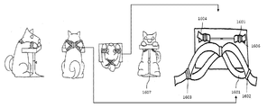
- 16 is a diagram illustrating a device configuration of the upper and lower body fixing for a specific animal species (dog, cat) according to an embodiment of the present invention.
- 17 is a diagram illustrating a configuration of a face fixing part according to an embodiment of the present invention.
- FIG. 18 is a diagram illustrating the configuration of the posture fixing and position adjusting unit for a particular animal species (cows) according to an embodiment of the present invention.
- FIG. 19 is a diagram illustrating the configuration of the posture fixing and position adjusting unit for a specific animal species (deer) according to an embodiment of the present invention.
- 20 is a diagram illustrating the configuration of the posture fixing and position adjusting unit for a specific animal species (dog, cat) according to an embodiment of the present invention.
- 21 is a flowchart illustrating a method of performing animal motion fixing according to an embodiment of the present invention.
- 22 is a block diagram schematically illustrating an image acquisition unit according to an embodiment of the present invention.
- FIG. 23 is a block diagram schematically illustrating an image acquisition unit according to an embodiment of the present invention.
- 24 is a view illustrating a device configuration of a photographing unit for moving the lens module and the sensor according to the distance control principle of the distance control module according to an embodiment of the present invention.
- 25 is a diagram illustrating a configuration of a photographing unit that adjusts the distance between the lenses in the lens module according to the distance adjusting principle of the distance adjusting module according to an embodiment of the present invention.
- 26 is a diagram illustrating a device configuration of a shooting guide unit according to an embodiment of the present invention.
- FIG. 27 is a diagram illustrating a device configuration of a lighting unit according to an embodiment of the present invention.
- FIG. 28 is a diagram illustrating a method of an image photographing unit for obtaining a nose pattern image to be recognized by an image recognition unit according to an embodiment of the present invention.
- FIG. 29 is a view illustrating a method of adjusting an angle of view and a focus (distance) by moving a lens module or a sensor of a photographing unit according to an exemplary embodiment of the present invention.
- FIG. 30 is a view for explaining a method of adjusting the angle of view and focus (distance) by moving the lenses in the lens module of the imaging unit according to an embodiment of the present invention.
- FIG. 31 is a view illustrating a method of adjusting an angle of view and a focus (distance) by adjusting the angle of view angle adjusting lens and the guide body of a photographing guide unit to fit a specific animal species (cow, deer) according to an embodiment of the present invention.
- 32 is a view for explaining a method of adjusting the angle of view and focus (distance) by adjusting the angle of view angle adjustment lens and the guide body of the shooting guide to fit a particular animal species (dog) according to an embodiment of the present invention. .
- 33 is a view for explaining a method of adjusting the angle of view and focus (distance) by adjusting the angle of view angle adjusting lens and the guide body of the shooting guide to fit a particular animal species (cat) according to an embodiment of the present invention.
- FIG. 34 is a diagram illustrating an image of the same recognized animal (dog) taken using different photographing guides according to an embodiment of the present invention.
- FIG. 35 is a comparison example of obtaining a nose pattern image of the same animal (dog) using the illumination method (direct light) and the illumination method (indirect light) of a general camera according to an embodiment of the present invention.
- 36 is a block diagram schematically illustrating an image analyzer according to an exemplary embodiment of the present invention.
- FIG. 37 is a diagram illustrating a method of obtaining a nose pattern snapshot in the photographing mode according to an embodiment of the present invention.
- FIG. 38 is a flowchart illustrating a method of obtaining a nose pattern image of an image acquisition unit according to an embodiment of the present invention.
- 39 is a block diagram schematically illustrating an image recognition unit according to an embodiment of the present invention.
- FIG. 40 is a flowchart illustrating a method of analyzing and recognizing an animal's nose pattern image according to an embodiment of the present invention.
- 41 is a block diagram schematically illustrating a region of interest setting unit according to an embodiment of the present invention.
- FIG. 42 is a diagram illustrating a method of setting a nostril boundary as an embodiment of the present invention.
- FIG. 43 is a view illustrating a method of approximating the boundary of the nostrils with a curve (circle, ellipse) as an embodiment of the present invention.
- FIG. 43 is a diagram illustrating a method of dividing an area between curved areas except for the inside of an approximate curve (circle, ellipse) as an embodiment of the present invention.
- FIG. 44 is a view illustrating a method of distinguishing regions located on opposite sides of the nostrils between the curves excluding the inside of the approximate curves (circles, ellipses) as an embodiment of the present invention.
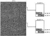
- 45 is a diagram illustrating a method of setting a rectangular region between approximation curves (circles and ellipses) as a region of interest as an embodiment of the present invention.
- FIG. 46 is a diagram for explaining that a region of interest from the same nose pattern image varies according to an approximation curve (circle, ellipse) as an embodiment of the present invention.
- FIG. 47 is a diagram illustrating a process of generating a standard region of interest from a preset region of interest as an embodiment of the present invention.
- FIG. 48 is a block diagram schematically illustrating a nose pattern code generation unit according to an embodiment of the present invention.
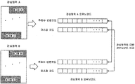
- 49 is a diagram illustrating a process of generating a nose pattern code from a region of interest as an embodiment of the present invention.
- FIG. 50 is a diagram illustrating a process of dividing a region of interest into a region of a specific size and generating a frequency transform nose pattern code from the divided cell region as an embodiment of the present invention.
- FIG. 51 is a diagram illustrating a comparison between a theoretical calculation area and an actual calculation area used when generating a frequency conversion code through a Garbor transform, a Gabo cosine transform, and a Heirloom sine transform as an embodiment of the present invention.
- FIG. 52 is a block diagram schematically illustrating a nose pattern code comparison decision unit according to an embodiment of the present invention.
- 53 is a diagram illustrating a method of authenticating a nasal pattern code to basic matching as an embodiment of the present invention.
- FIG. 54 is a diagram illustrating a case where a location of a region of interest selected for comparing a nasal pattern code in a nasal pattern of the same individual is different as an embodiment of the present invention.
- 55 is a diagram illustrating a method of authenticating a nose pattern code by moving matching as an embodiment of the present invention.
- FIG. 56 is a diagram illustrating a case in which a region of interest selected for comparing a nasal pattern code in a nose pattern of the same individual has a different ratio of top, bottom, and left and right.
- 57 is a diagram illustrating a method of authenticating a nasal pattern code by region division moving matching as an embodiment of the present invention.
- FIG. 58 is a view illustrating an example of a process of authenticating a nose pattern code by moving matching by gabor sign transformation according to an embodiment of the present invention.
- FIG. 59 is a view illustrating an example of a process of authenticating a nose pattern code by region division shift matching by Gabor sign transformation as an embodiment of the present invention.
- FIG. 60 is a diagram illustrating a method for identifying (one-to-many matching) with a nose pattern code as one embodiment of the present invention.
- Verification is used for one-to-one (1: 1) matching
- Identification or Searching is used for one-to-many (1: N) matching
- Recognition is used to mean the recognition of the entire large system including the above authentication and identification (eg image recognition unit).
- the animal nose pattern means a pattern having a nose pattern beads shape and a nose pattern bone shape, and even the same paper has a characteristic that the size of the nose pattern is different if the size of the nose part varies depending on the body size.
- the present invention relates to an apparatus and a method for recognizing an animal object to be recognized (hereinafter, referred to as a “recognized animal”) by using nose patterns of animals whose nose patterns are identifiable.
- Auxiliary devices hereinafter referred to as "animal motion fixation”
- animal motions which perform the fixing of the movement of animal objects to obtain a possible nose pattern image (hereafter referred to as "nose pattern image”).
- Image capture device hereafter referred to as “image acquisition unit” and image acquisition unit for removing nose pattern image of animal object with fixed movement by fixed unit to remove noise, Create a corrected image (Augmented Nose-Pattern Image) by using techniques such as image clarity enhancement, Individual animals comprising a device for generating, registering, authenticating and identifying an image code (hereinafter referred to as a "nose pattern code”) from a calibrated nose pattern image (hereinafter referred to as an "image recognition unit”).
- a recognition apparatus and method are provided.
- FIG. 1 is a conceptual diagram of an animal object recognition apparatus according to an embodiment of the present invention.
- Animal object recognition apparatus 100 and the animal motion fixing portion 101 for fixing the posture of the animal to obtain the identifiable nose pattern image necessary for recognizing the animal
- the image recognition unit 103 may be configured to generate, register, authenticate, and identify an image code from a nose pattern image (or a corrected nose pattern image).
- the image acquisition unit 102 may include an image analysis unit to be described later.
- the image analyzer may be included in the image recognition unit 103. That is, the configuration can be variously modified depending on the needs of the user or the purpose of the designer.
- Figure 2 illustrates the shape of the nose pattern of a particular animal species (deer) in accordance with an embodiment of the present invention.
- the nose portion of the deer according to the exemplary embodiment of the present invention is photographed by an image acquisition unit, and is composed of a region having a nostril and a nose pattern.
- the area to be photographed of the nose pattern is called beads (below "nose pattern beads") that are raised from the surface in the shape of beads and ridges corresponding to the boundary of the beads. It is composed of
- Figure 3 illustrates the shape of the nose pattern of a particular animal species (dog) according to an embodiment of the present invention.
- the nose portion of the dog according to an embodiment of the present invention was taken by the image acquisition unit, the size is different compared to the deer of Figure 2, but the shape of the nose pattern beads and nose pattern It consists of bone shapes.
- the deer has a very large nose pattern like a cow, and the dog has a relatively small nose pattern like a cat, compared to a cow and a deer. .
- the physiological characteristics of the nose area which is a target area for acquiring the nose pattern of the animal described above, will be described.
- FIG. 4 illustrates an image in which a portion covered with water, which is a physiological feature of a nose portion of an animal, is reflected by light according to an embodiment of the present disclosure.
- FIG 4 it shows that the nasal area of the animal is wet with water, and in fact, most of the daily life is known to have water (moisture) in the nose of a healthy animal. Therefore, if you touch a material such as glass or paper to the area of the nose without ink as in the conventional method, the problem is that the bite of the nose is likely to cause blurry images or the bite of the nose is prominent with the inscription. have.
- the overall size of the nose is different, the length of the nose is different, and the length of the legs and the size of the face are also different. Therefore, there is a need for a method and apparatus that considers this when acquiring the nose pattern of an animal.
- Animals are of the same breed but differ in character. In practice, it is easy to do the task of acquiring a nose pattern, in the case of encountering an exceptionally mild individual, but most of the subjects are afraid of new work tools or inspectors to avoid them. Resistant or anti-aggressive behavior can lead to many difficulties, even with the help of breeders or experts.
- an animal object recognition apparatus performs an operation of fixing a movement of a target animal to obtain an identifiable nose pattern image necessary for recognizing the animal.
- Correct the nose pattern image obtained from the image capturing unit and the image capturing image obtained by capturing the nose pattern image of the animal to which the motion of the animal is fixed by the motion fixing unit and the animal motion fixing unit, or the nose pattern image ( Or corrected nose pattern image) may be configured to include an image recognition unit for generating, registering, authenticating and identifying a nose pattern code.
- Animal motion fixing means the entire device for fixing the animal from moving while photographing the nose pattern image of various kinds of animals
- the image acquisition unit according to the invention software for acquiring the nose pattern image from various kinds of animals and Means all devices including hardware
- the image recognition unit means all devices including the necessary software and hardware for image recognition.
- FIG. 5 is a diagram briefly illustrating that animal object recognition of a recognized animal is actually performed by using the animal object recognition apparatus according to an embodiment of the present invention.
- FIG. 6 is a view illustrating a shape viewed from various aspects in order to easily understand the form of the animal object recognition apparatus used in FIG. 5 according to an embodiment of the present invention.
- FIG. 5 and 6 it can be understood how a task performer actually applies the animal object recognition apparatus illustrated in FIG. 1 according to an embodiment of the present invention to a recognized animal.
- FIG. 7 is a block diagram illustrating a configuration of an animal object recognition apparatus in which an animal motion fixing unit 701, an image acquisition unit 702, and an image recognition unit 703 are independent types according to an embodiment of the present invention.
- 8 is a view illustrating a configuration of an animal object recognition apparatus having a form in which an animal motion fixing unit 801 and an image acquisition unit 802 are linked together as one, and independent from the image recognition unit 803, according to an embodiment of the present invention. It is a block diagram.
- FIG. 9 is a diagram illustrating a configuration of an animal recognition apparatus of a type in which an image acquisition unit 902 and an image recognition unit 903 are linked together and independent from the animal motion fixing unit 901 according to an embodiment of the present invention.
- 10 is a diagram illustrating a configuration of an animal object recognition apparatus in which an animal motion fixing unit 1001, an image acquisition unit 1002, and an image recognition unit 1003 are linked to one according to an embodiment of the present invention. to be.
- the apparatus for recognizing an animal object may be composed of an animal motion fixing unit, an image acquisition unit, and an image recognition unit according to an animal species, an execution place, a purpose, and a need, and may be configured independently of each part.
- various modifications may be made in various forms such that specific parts may be combined together.
- FIG. 11 is a flowchart illustrating a method of performing animal object recognition apparatus according to an embodiment of the present invention.
- the method for performing animal object recognition proceeds in the following order.
- the animal motion fixing part suitable for the animal to be recognized is selected (S1101).
- the selected animal motion fixation is fixed to prevent the corresponding animal to move (S1102).
- the nose portion of the identified animal fixed by the animal motion fixing unit is connected to the image acquisition unit to obtain a nose pattern image (S1103), and then acquires the nose pattern image of the object to be recognized by the image acquisition unit (S1104).
- the obtained nose pattern image may be transmitted to the image recognition unit, or may be converted into a corrected nose pattern image in the image recognition unit.
- the image recognition unit generates a nose pattern code from the nose pattern image transferred after being acquired by the image acquisition unit (S1105).
- the image recognition unit registers the generated nose pattern code, and authenticates and identifies the object of the animal to be recognized using the nose pattern code registered in advance and the nose pattern code acquired for recognition (S1106).
- steps S1101 to S1106 are described as being sequentially executed. However, this is merely illustrative of the technical idea of an embodiment of the present invention, and the general knowledge in the technical field to which an embodiment of the present invention belongs. Those skilled in the art will appreciate that various modifications and variations may be applicable by changing the order shown in FIG. 11 or by executing one or more steps of steps S1101 to S1106 in parallel without departing from the essential characteristics of one embodiment of the present invention. 11 is not limited to the time series order.
- the animal motion fixing unit aims to stop the movement of the recognized animal for a predetermined time to acquire the nose pattern image.
- the animal may be injured due to an unexpected accident, such as pulling back its face or bumping a part of the body while working. Therefore, these unexpected behaviors and accidents can increase the difficulty of work and increase the economic cost.
- the angle at which the lens is viewed from the nose of the target animal should not be greatly deviated from the front direction of the lens. It should be located in the front direction to obtain a good nose pattern image. As mentioned earlier, it is very difficult to stop a person's posture so that the animal meets these conditions without any device in the absence of the animal's cooperation.
- the Animal Motion Governing Body shall be configured so that four essential objectives can be fulfilled:
- the first is to allow the movement of the animal to be stopped for the time necessary to acquire the nose pattern image of the animal.
- the second is to ensure the safety of inspection personnel and equipment that may occur when performing work.
- the nose part is fixed so that a good nose pattern image can be easily obtained from the image acquisition unit so that the recognized animal can be recognized by the image recognition unit.
- FIG. 12 is a block diagram schematically illustrating an animal motion fixing unit according to an embodiment of the present invention.
- the animal motion fixing unit includes a posture fixing unit 1201 for fixing the posture of the animal to be recognized. It may also be configured by adding a position adjusting unit 1202 for adjusting the stride or height or balance of the posture fixing to match the physical characteristics of the animal to be recognized.
- FIG. 13 is a block diagram schematically showing the posture fixing in accordance with an embodiment of the present invention.
- the face part When acquiring the nose pattern image, it is thought that it is possible to fix only the face part (hereinafter, “the face part”), but as described above, even if the face part of the animal to be recognized is fixed due to the nature of the animal object, It can be taken out or struggling. This can lead to severe movement of the animal's neck (neck), shoulders (hereafter referred to as “upper body”), forelimbs (foot) or hind legs (foot) (hereafter referred to as “lower body”).
- the face part is fixed so that the image acquiring part can comfortably put the face part of the animal to be recognized for the time to acquire the nose pattern image required for recognition, and prevent the movement of the face part.
- the upper body and the face is fixed, most animals are fixed in movement.
- the posture fixing portion is the upper body fixing portion 1301 and the face portion for the purpose of fixing the upper body portion of the animal to be recognized. It includes a face fixing part 1302 for the purpose of fixing, and may be configured by adding a lower body fixing part (1303) for fixing the lower part of the object to be recognized.
- FIG. 14 is a block diagram schematically showing a position adjusting unit according to an embodiment of the present invention.
- the upper body fixing portion 1401 may further include a height adjusting unit 1404 for adjusting to fit the height of the target animal, the lower body fixing portion 1403 is a stride for adjusting the size of the stride of the animal
- the adjuster 1406 may be further configured.
- the face fixing unit 1402 is a balance control unit 1405 for adjusting the face portion of the animal to be balanced with the image acquisition unit, height adjustment unit for adjusting the size (height) of the animal to be recognized (1407). ) May be further configured.
- the posture fixing unit and the position adjusting unit may be configured in various forms such as adding or excluding some of the above-described parts according to the shape and size of the animal species to be recognized.
- FIG 15 is a view illustrating a device configuration of the upper and lower body fixing for a specific animal species (cow, deer) according to an embodiment of the present invention
- Figure 16 is a specific animal according to an embodiment of the present invention
- the diagram illustrates the device configuration of the upper and lower body fixing parts for dogs (dogs and cats).
- the upper and lower body governments may be composed of one, or may be composed of each part independently, and may be configured in various forms such that specific parts may be combined together. Modifications are possible.
- the upper body fixing portion of the animal (cow and deer) is a device for fixing the upper body of the animal, the upper body fixing members (1501, 1601) and the upper body fixing the upper body of the animal to be recognized It consists of upper body locking members (1502, 1602) that serves to fix the fixing member.
- the upper body pressure control member (1503, 1603) that serves to apply pressure to the upper body fixing member for fixing the upper body of the animal can be configured to be added.
- the upper body fixing members 1501 and 1601 may include a cover covering the upper body portion or a belt, a string, a cable, or the like covering a portion of the upper body portion.
- the cover is made of materials such as synthetic fiber, rubber, cloth, etc., which are not easily torn, and the upper body can be fixed by a belt, a string, a cable, etc., which can be adjusted in length according to the upper body size of the animal to be recognized.
- the upper body locking members 1502 and 1602 locking the upper body fixing member to prevent the upper body fixing member from being released after fixing the object to be recognized may be configured as a manual locking member or an electronic locking member.
- the upper body pressure regulating member (1503, 1603) is a pressure injector for pressurizing the pressure (such as reducing the volume and length of the upper body fixing member or injecting air or liquid) so that the upper body fixing member can press the upper body of the animal to be recognized.
- a pressure measuring member capable of monitoring the applied pressure.
- the lower body fixing part for fixing the lower body of the animal the role of fixing the lower body fixing members (1504, 1604) and lower body fixing member for fixing the lower body of the animal to be recognized. It consists of a lower body locking member (1505, 1605).
- the lower body pressure control member (1506, 1606) that serves to apply pressure to the lower body fixing member for fixing the lower body of the animal can be configured to be added.
- the lower body fixing member 1507 and 1607 may be configured to fix the lower body fixing part to a specific position of the surface or work tool in consideration of this.
- the lower body fixing members 1504 and 1604 may include a cover covering the lower body portion or a belt, a string, a cable, or the like covering a portion of the lower body portion.
- the cover is made of materials such as synthetic fiber, rubber, and cloth that are not easily torn, and the lower body can be fixed with a belt, a string, a cable, etc., which can be adjusted in length according to the size of the lower body of the animal to be recognized.
- the lower body locking members 1505 and 1605 that lock the lower body fixing member to prevent the lower body fixing member from being released after fixing the animal can be configured as a manual locking member or an electronic locking member.
- the lower body pressure control member is a pressure injector for pressurizing the pressure (such as reducing the volume and length of the lower body fixing member or injecting air or liquid) so that the lower body fixing member can press the upper body of the animal to be recognized.
- a pressure measuring member capable of monitoring the applied pressure.
- the lower body fixing member 1507, 1607 may be composed of a lower body supporting member for fixing the lower body fixing to a specific position of the ground surface or work tools, and a connecting member for connecting the lower body supporting member.
- the lower support member and the connecting member may have various shapes including rings, depending on species and varieties.
- the lower support member and the connecting member may be made of metal such as iron, and not easily torn synthetic fiber, rubber or cloth, which is the same as the lower body fixing part. Can be configured.
- 17 is a diagram illustrating a configuration of a face fixing part according to an embodiment of the present invention.
- the facial fixation part is composed of a cradle 1701 for placing a facial part of an animal to be recognized.
- a face fixing member 1702 for fixing the nose portion of the animal to be recognized may be configured.
- the cradle 1701 is made of various materials such as wood, plastic, rubber, metal, etc., and bears the weight of the face of the animal to be perceived in various forms depending on the species and breed so that the jaw of the face can be comfortably adhered to. It may have a shape and an attachment.
- the face fixing member 1702 is used when the nose portion of the animal to be stopped cannot be stopped by the cradle alone, and a belt, a string, and a cable covering the nose portion (or mouth portion) or a portion of the nose portion (or mouth portion) is covered. And the like.
- the cover is made of materials such as synthetic fiber, rubber, cloth, etc., which are not easily torn, and the nose can be fixed with a belt, a string, a cable, etc., which can be adjusted in length according to the size of the animal to be recognized.
- the face locking member 1703 for locking the face fixing member to prevent the face fixing member from being released after fixing the animal can be composed of a manual face locking member or an electronic face locking member.
- the face pressure adjusting member 1704 is applied to the pressure injector (pressing the volume and length of the face fixing member or injecting air or liquid) such that the face fixing member can press the nose portion of the animal to be recognized. It can be composed of a pressure measuring member capable of monitoring the pressure.
- the facial fixation can be configured by adding a support (1705) to support the weight of the face of the animal by fixing the bottom of the facial fixation to a specific position of the surface or work tools, depending on species and breeds. Since the weight is different, it is mainly made of a material such as iron, rock or wood that can support the weight, and may have various shapes including a ring shape.
- the position control unit is a device for adjusting the posture fixing unit so that the animal can maintain the most comfortable posture in consideration of the physical characteristics of the animal.
- the position control unit includes a height adjusting unit, an equilibrium adjusting unit, and a stride adjusting unit.
- the height adjustment unit (1801, 1804) for the specific animal species (small) is the height of the object to be recognized when connecting the upper and lower body fixing ( Height) to adjust the length or face fixing device to the height of the face of the animal.
- the height adjusting unit 1801 connecting the lower and upper fixing parts is a connecting member 1802 including a belt, a string, and a cable connecting the upper and lower fixing parts, and adjusting the length of the connecting member. It may be composed of a member 1803.
- the height adjustment unit 1804 for adjusting the height of the face fixing part is a connecting member 1805 for connecting with the support for supporting the bottom and the bottom of the face fixing part and the height adjusting member 1806 for adjusting the height of the connecting member. It can be composed of).
- the balance control unit 1807 for a particular animal species (small) faces the image acquisition front of the face of the animal in the cradle of the facial fixation It is to adjust the left, right, top and bottom of the cradle of the facial relief to make it visible.
- the balance control unit 1807 is installed inside or outside the cradle of the face fixing part, and is composed of a balance detection sensor for detecting horizontality and a display unit for displaying horizontality.
- the equilibrium detection sensor may include a gravity sensor for generating a signal by detecting a direction in which gravity moves, a gyro sensor for generating a signal by detecting a change in inclination, and a pressure sensor for detecting a small pressure change.
- the stride length adjustment unit 1808 for a particular animal species (small) is fixed to the size of the animal species and individuals when fixing the lower body portion in the lower body fixing part
- the device for adjusting the stride length it may be composed of a connecting member 1809 consisting of a belt, a string and a cable for connecting both lower body parts of the lower body fixing portion and an adjusting member 1810 for adjusting the length of the connecting portion.
- the height adjustment unit (1901, 1904) for the specific animal species (deer) is the height of the object to be recognized when connecting the upper and lower body fixing ( Height) to adjust the length or face fixing device to the height of the face of the animal.
- the height adjusting unit 1901 connecting the lower and upper fixing parts is a connecting member 1902 consisting of a belt, a string, and a cable connecting the upper and lower fixing parts, and adjusting the length of the connecting member. It may be composed of a member 1903.
- the height adjustment unit 1904 for adjusting the height of the face fixing portion is a connecting member 1905 for connecting with the support for supporting the bottom and the bottom of the face fixing portion and height adjustment member for adjusting the height of the connecting member (1906) It can be composed of).
- the balance control unit 1907 for a particular animal species (deer) faces the image acquisition front of the face of the animal in the cradle of the face fixing It is to adjust the left, right, top and bottom of the cradle of the facial relief to make it visible.
- the balance control unit 1907 is installed on the inside or outside of the cradle of the face fixing part, and is composed of a balance detection sensor for detecting horizontality and a display unit for displaying horizontality.
- the equilibrium detection sensor may include a gravity sensor for generating a signal by detecting a direction in which gravity moves, a gyro sensor for generating a signal by detecting a change in inclination, and a pressure sensor for detecting a small pressure change.
- the stride length adjusting unit 1908 according to a specific animal species (small) according to an embodiment of the present invention has a size corresponding to the size of an animal species and an individual when the lower body is fixed in the lower body fixing part.
- a device for adjusting the stride length accordingly it may be composed of a connecting member 1909 consisting of a belt, a string and a cable connecting both lower body parts of the lower body fixing portion and an adjusting member 1910 for adjusting the length of the connecting portion.
- the height adjustment unit 2001 for a particular animal species is the height of the object to recognize when connecting the upper and lower body fixing ( It is a device that adjusts the face fixing part to the height up to the facial part of the animal.
- the lower body government may be configured as a cradle for the facial tissue.
- the adjustment member may be configured on the front or upper portion of the cradle of the face fixing part.
- the height adjusting part 2001 for adjusting the height of the face fixing part is a connecting member 2002 for connecting the support for supporting the cradle and the floor of the face fixing part and a height adjusting member for adjusting the height of the connecting member 2003.
- the balance control unit 2004 for a particular animal species is the face of the animal to face the image acquisition unit in the cradle of the face fixing In order to be able to see, the left, right, top and bottom of the cradle of the facial relief government are adjusted.
- the balance control unit 2004 is installed on the inside or outside of the cradle of the face fixing part, and is composed of a balance detection sensor for detecting horizontality and a display unit for displaying horizontality.
- the equilibrium detection sensor may include a gravity sensor for generating a signal by detecting a direction in which gravity moves, a gyro sensor for generating a signal by detecting a change in inclination, and a pressure sensor for detecting a small pressure change.
- the stride length adjusting unit 2005 for a particular animal species (dog or cat) has a size of an animal species and an individual when the lower body is fixed in the lower body fixing part.
- the device for adjusting the stride length it may be composed of a connecting member (2006) consisting of a belt, a string and a cable for connecting both lower body parts of the lower body fixing portion and an adjusting member (2007) for adjusting the length of the connecting portion. .
- 21 is a flowchart illustrating a method of performing animal motion fixing according to an embodiment of the present invention.
- the method of performing the animal motion fixing proceeds in the following order.
- the animal motion fixing part suitable for the animal to be recognized is selected (S2101).
- the total size, leg length, foot size, face size, and nose position of the target animal are selected in consideration of the selection.
- the upper body fixation is first installed on the recognized animal (S2102). Fix the upper body of the animal to the upper body fixing (S2103) installed. In this case, the length of the upper body fixing member and the pressure applied to the upper body fixing member and the upper body pressure adjusting member are adjusted according to the length of the shoulder circumference of the target animal.
- the lower body fixing part is installed on the object to which the upper body part is fixed by the upper body fixing part (S2104). At this time, the lower body of the object is fixed using the lower body fixing part installed (S2105). At this time, the circumferential length of the lower body fixing member and the pressure applied to the lower body fixing member and the lower body pressure adjusting member are adjusted according to the circumference of the feet or legs of the animal to be recognized. In addition, by using the stride control unit to adjust to the stride of the target animal, if it is necessary to connect the upper and lower body of the government fixed height using the height adjustment unit in consideration of the height of the object to be recognized.
- a facial fixation system is installed on the identified animal fixed by the upper and lower governments (S2106).
- the height to the face area is adjusted by using the height adjustment portion, and the equilibrium adjustment portion so that the nose portion of the animal to be located in the front direction with the image acquisition portion as possible.
- steps S2101 to S2107 are described as being sequentially executed.
- this is merely illustrative of the technical idea of an embodiment of the present invention, and those skilled in the art to which the present invention pertains may include Since various modifications and variations may be applicable by changing the order described in FIG. 21 or executing one or more steps in steps S2101 to S2107 in parallel without departing from the essential characteristics of one embodiment of the present invention, FIG. 21. Is not limited to time-series order.
- the image acquisition unit captures and acquires a nose pattern image of the animal to be recognized.
- the nose pattern is different according to the species of the animal, and the size of the nose pattern beads and the nose pattern bone shape, the shape of the nose pattern is also very different.
- the overall size of the nose is different, and the length of the nose also has different physical characteristics. Therefore, there is a problem that it is very difficult for non-experts who are not trained to use digital cameras or camcorders to obtain good nasal pattern images so that the recognized animals can be recognized by the image recognition unit using these devices.
- the image acquisition unit is configured to perform six essential purposes.
- a good nose pattern image is obtained so that the recognized part can be recognized by the image recognition unit without directly contacting the part where the nose pattern exists.
- the second is to obtain a good nose pattern image so that the nose recognition can be recognized by the image recognition unit according to the species of the animal to be recognized.
- the image recognition unit obtains a good nose pattern image to enable the recognition of the animal.
- the image recognition unit obtains a good nose pattern image to recognize the animal to be recognized.
- the image recognition unit acquires a good nose pattern image so that the recognized animal can be recognized.
- 22 is a block diagram schematically illustrating an image acquisition unit according to an embodiment of the present invention.
- the image acquisition unit is composed of an image taking unit 2201 for the purpose of shooting a nose pattern image of the animal to be recognized, the nose taken by the image taking unit
- an image analysis unit 2202 may be configured to manage a series of various information and signals generated in this process.
- FIG. 23 is a block diagram schematically illustrating an image capturing unit according to an embodiment of the present invention.
- the image pickup unit As shown in Figure 23, the image pickup unit according to an embodiment of the present invention, the photographing unit 2301 for photographing the nose pattern image of the animal, the characteristic and physical characteristics of the nose pattern when photographing the nose pattern image of the animal According to the characteristics of the field of view (Field of view) and the nose portion of the animal to be recognized is composed of a photographing guide unit 2302 which serves to block the external light.
- the photographing guide unit 2302 which serves to block the external light.
- the lighting unit 2303 using indirect illumination to adjust the light source and light reflection considering the moisture of the nose may be added.
- 24 and 25 are views illustrating a device configuration of the photographing unit according to the distance control principle of the distance control module according to an embodiment of the present invention.
- the photographing unit directly photographs the nose pattern image according to an embodiment of the present invention, and is referred to as a lens module 2401 (hereinafter referred to as a “lens module”) composed of one or more lenses.
- Image sensor 2402 hereinafter referred to as “sensor” of mega pixel CMOS, CCD, etc., which form a nose pattern image, and the lens in the shooting guide unit 2404 by moving the lens module and the sensor to adjust the angle of view and focus.
- a distance adjusting device 2403 hereinafter, referred to as a “distance adjusting module” for controlling the distance between the lens module and the lens module and the sensor.
- the distance control module 2403 is a lens module or a small rotating motor for moving a plurality of lenses in the lens module is fixed to one side of the device, the gear is fastened to the rotary shaft of the rotary motor, and the gear is installed on the rotary shaft of the motor It can be configured as a rack gear to convert the rotational motion of the motor into a linear motion.
- a guide rail may be configured to guide the lens module 2401 and the sensor 2402 for linear reciprocation by the rack gear so that the linear reciprocating motion can be always performed at a predetermined position.
- the lens module 2501 and the sensor 2502 according to an embodiment of the present invention is fixed to the distance adjusting module 2503 to adjust the distance between the lenses in the lens module without moving
- the configured photographing unit may be configured.
- 26 is a diagram illustrating a device configuration of a shooting guide unit according to an embodiment of the present invention.
- the photographing guide unit adjusts an angle of view and a cover 2601 in contact with the skin of the circumferential part of the nose when the nose portion of the animal enters the photographing guide unit.
- the adjustment lens 2603 and the guide body 2602 for adjusting the distance between the nose portion of the object and the angle of view adjustment lens (2603).
- the cover 2601, the angle of view adjustment lens 2603, and the guide body 2602 may be configured differently according to the species of the animal.
- Cover 2601 is a device that covers the area where the animal's nose is in contact with the skin, and has a color (dark color system such as black) to block the light from entering the outside from the outside, the object is not hated It is made of synthetic fibers or materials such as rubber, cloth and plastic.
- the cover may be configured to be given a favorite odor according to the species of the animal, it may be configured to be detachable to be easily separated from the body to easily change the cover.
- the angle of view adjustment lens 2603 is a reduction lens for a species of a species having a larger nose area than a dog, and a zoom lens for a small object of a nose area as a magnifying lens.
- the nosed animal is composed of standard lenses.
- the standard lens described above refers to a single or multiple angle of view adjustment lenses for capturing an area necessary for recognizing the area of the dog's nose in the nose pattern image
- the reduction lens and the magnification lens refer to the standard lens.
- the range of the field of view means a reduced (e.g., wide-angle lens) or an enlarged lens (e.g. macro lens).
- Guide body 2602 is composed of an outer portion for blocking the light coming from the outside and the inner portion that the nose portion of the animal is received, the inner portion may be configured with a light. According to the length of the guide body, the distance between the angle of view control lens and the nose of the animal to be controlled is adjusted, and the optimum length for the type of angle of view adjustment lens obtained through the experiment can be applied.
- FIG. 27 is a diagram illustrating a configuration of a lighting unit according to an embodiment of the present invention.
- the lighting unit has a specific wavelength region suitable for the characteristics of the species in consideration of secondary problems such as absorption of light and damage to skin tissue, which may occur due to moisture in the nose area.
- the light source 2701 using only the light source of the light and the light path member 2703, which is a space in which the illumination proceeds to use the indirect light without using the direct light, and a film of a special material to reduce the reflection of light due to the moisture of the nose area It consists of a reflection control member (2702) for indirect illumination through.
- the light source 2701, the reflection control member 2702, and the light passage member 2703 may be configured differently depending on the species of animal.
- the light source 2701 can adjust the amount of light and avoid the ultraviolet wavelength range where the light of the nose absorbs the infrared rays due to the bite of the nose or may cause damage to the skin tissue, and to fit the nose pattern of the species. Use a light source with a specific wavelength range. In the present invention, any kind of light source may be used as long as it meets the above spirit.
- the reflection control member 2702 absorbs or reflects a light source capable of adjusting the amount of light and a portion of the light emitted from the light source, and transmits the remaining part to indirect illumination by the light transmitted through the entire nose area of the cognizant animal that enters the inside of the photographing guide. do.
- the amount of light absorbed or reflected and transmitted can be selected and controlled from a film made of a special material such as Hanji, translucent tracing paper or glass, and the film of the material used for the reflection control member is a space inside the light passage member 2703. May also be used.
- the light path member 2703 is an indirect light that transmits a part of the light from the light source through the light path member instead of the direct light through which the light source directly illuminates the nose of the target animal. In order to use, it selects and combines inside the film
- the depth of field of the camera needs to be adjusted.
- the aperture brightness, angle of view, focus (distance), and focus (distance) with the subject are adjusted. need.
- FIG. 28 is a diagram illustrating a method of an image photographing unit for obtaining a good nose pattern image to enable recognition of a target animal in the image recognition unit according to an embodiment of the present invention.
- the image capturing unit 2801 obtains a good nasal pattern image to enable recognition of the animal to be recognized by the image recognition unit through various methods.
- the photographing unit 2802 adjusts an angle of view and a focus (distance) by using the distance adjusting module 2805.
- the lens module 2811 or the sensor 2812 is moved to adjust the angle of view and focus (distance)
- the lens module 2811 and the sensor 2812 are fixed and the lens Move lenses (multiple lenses) 2813 within the module.
- the photographing guide unit 2803 adjusts the angle of view by using the angle of view adjustment lens 2806, and changes the length of the guide body 2807 according to the species to match the distance between the angle of view adjustment lens 2806 and the lens module 2815. Adjust the focus (distance).
- the lighting unit 2804 uses the light source 2808 as a light source having a specific wavelength region corresponding to the nose pattern of the species, and uses indirect lighting by using the light passage member 2809 and the reflection control member 2810, and indirect lighting.
- the image recognition unit obtains a good nasal pattern image so that the recognized animal can be recognized.
- FIG. 29 is a view for explaining a method of adjusting an angle of view and a focus (distance) by moving the lens module 2901 or the sensor 2902 of the photographing unit according to an embodiment of the present invention.
- the lens module 2901 and the sensor 2902 may be used alone or the lens module 2901 and the sensor 2902 respectively to adjust the angle of view and focus (distance) according to an embodiment of the present invention. Together to make a straight reciprocating motion by the distance control module.
- the distance a between the lens module 2901 and the sensor 2902 and the lens module and the photographing guide part 2903 are changed so that the distance b to the angle of view adjustment lens in the photographing guide part is changed.
- the angle of view and focus (distance) are adjusted.
- the length (c) of the photographing guide portion 2903 is predetermined according to the species of the animal to be recognized, has a fixed value, and the distances d1 and d2 between the lenses 2904 in the lens module are also fixed. have.
- the distance adjusting module may be configured to adjust the values of a and b by performing a linear reciprocating motion with the lens module 2901 alone or with the sensor 2902.
- the values of a and b are preset values according to the species of animals by the image analyzer so that a non-expert can easily obtain a good nose pattern image so that the image recognition unit can recognize the animal. ”) And can be adjusted within a certain range based on this.
- (B) looks at how to adjust the lens (many lenses) in the lens module.
- FIG. 30 is a view for explaining a method of adjusting the angle of view and focus (distance) by moving the lenses in the lens module of the imaging unit according to an embodiment of the present invention.
- the lenses 3004 in the lens module are linearly reciprocated by the distance adjusting module. Due to the movement of a plurality of lenses in the lens module, the distances d1 and d2 between the lenses 3004 in the lens module are changed, thereby adjusting the angle of view and focus (distance).
- the length (c) of the photographing guide part 3003 is predetermined according to the species of the animal to be recognized, and has a fixed value, and the distance a and the lens between the lens module 3001 and the sensor 3002. The distance b between the module and the angle of view adjustment lens in the photographing guide part 3003 is also fixed.
- the distance adjustment module may be configured to move only with the lenses 3004 in the lens module to linearly reciprocate the lenses (multiple lenses) to adjust only the values of d1 and d2, respectively.
- values of a and b may be set to be fixed to the reference setting value by the image analyzing unit so that a non-expert can easily obtain a good nose pattern image so that the recognized animal can be recognized by the image recognition unit.
- the image recognition unit will be described in detail how to adjust the angle of view and focus (distance) in the photographing guide in order to obtain a good nose pattern image to recognize the recognition of the animal.
- the angle of view lens and the guide body are used to adjust the angle of view and focal length.
- 31, 32, and 33 illustrate a method of adjusting the angle of view and focus (distance) by adjusting the angle of view angle adjusting lens and the guide body of the photographing guide unit to fit a specific animal species (cow, deer, dog, cat). It is a figure for following.
- the angle-of-view lens has a larger nose area than the dog, and the angle-of-view lens is a zoom lens, and the small-nose area is a magnification lens.
- the animal to be recognized consists of a standard lens.
- the length of the guide body may be configured to adjust the focal point (distance) with the nose portion (subject) of the animal by varying the length of the animal species.
- the angle of view adjusting lens 3101 is used as a reduction lens to adjust the angle of view and the focus (distance) to fit the animal species having a large nose area, and the focal point is used to adjust the focus (distance) with the nose part (subject) of the subject.
- a guide body 3102 whose length is set in advance to fit the distance is used.
- the distance to b) can also be adjusted.
- the angle of view adjustment lens 3201 is used as a standard lens to adjust the angle of view and focal point (distance) so that the nose part is adapted to an animal species similar to a dog, and the focal point (distance) with the nose part (subject) of the subject is adjusted.
- the guide body 3202 the length of which is set in advance to match the focal point (distance) is used.
- the distance a ′′ from the shooting portion to the lens module 3203 and the sensor 3204, the lens module 3203, and the angle of view adjustment lens 3201 in the shooting guide portion can also be adjusted.
- the angle of view adjusting lens 3301 is used as an enlarged lens to adjust the angle of view and the focus (distance) so that the nose area is suitable for a small animal species, and the focal point is used to adjust the focus (distance) with the nose part (subject) of the subject.
- the guide body 3302 is set in advance to fit the distance.
- FIG. 34 is a diagram illustrating an image of the same recognized animal (dog) taken using different photographing guides according to an embodiment of the present invention.
- the first image is taken using the shooting guide section for the animal species (cat) with a small nose area
- the second image is taken using the shooting guide section for the animal species similar to a dog.
- FIG. 34 only a portion of the nose pattern is obtained when the region of the nose portion of the same recognized animal (dog) according to an embodiment of the present invention is photographed with a photographing guide unit suitable for a cat.
- a photographing guide unit suitable for a cat When shooting with a guide for a dog, all nose pattern images are acquired, and when it is acquired with a shooting guide for a cow or deer, it is acquired up to the range of the face. Therefore, even if the same object (dog), it can be seen that the range of the acquired nose pattern image is different as the shooting guide part is different.
- FIG. 34 shows human adult fingers (scale comparison).
- FIG. 35 is a comparison example of obtaining a nose pattern image of the same animal (dog) using the illumination method (direct light) and the illumination method (indirect light) of a general camera according to an embodiment of the present invention.
- a light source, a light passage member, and a reflection control member are used to control light reflection using indirect lighting as shown in FIG. 35.
- the lighting unit avoids the ultraviolet wavelength range that may absorb the infrared rays due to the bite of the nose or may damage the skin tissue, and to use the light source and the indirect lighting of the specific wavelength region suitable for the characteristics of the species. desirable.
- the nose area Due to the bite of the light reflection occurs badly there are a lot of visible parts (white part). This part later acts as a very big obstacle to recognition in the image recognition unit, so acquiring an image without these light reflections helps improve the recognition rate if possible.
- the image analysis unit not only analyzes and acquires the nose pattern image acquired by the image capturing unit, but also manages a series of various information and signals generated in this process, and may be configured in addition to the image acquisition unit as well as the image recognition unit. have.
- 36 is a block diagram schematically illustrating an image analyzer according to an exemplary embodiment of the present invention.
- the image analyzing unit may include a main operation unit 3601, a buffer 3602, a reference database (DB) 3603, and a communication unit 3604.
- DB reference database
- the display unit 3605 may be further configured to allow the user to quickly obtain a good nose pattern image by allowing the user to see the nose pattern image of the target animal photographed by the image pickup unit.
- the main operation unit selects a good nose pattern image from among the nose pattern images taken by the image capturing unit so that the image recognition unit can recognize the target animal.
- the image recognition unit may perform image recognition to enable recognition (authentication and identification) of the animal to be recognized.
- a nose pattern image is calculated according to a measurement item (hereinafter referred to as “characteristic item”), and the quality of the image (hereinafter referred to as “item quality degree”) is calculated.
- Characteristic item the measurement item
- item quality degree the quality of the image
- Select an image that satisfies the threshold value hereinafter referred to as the “standard quality diagram” as a reference for. If there is no nose pattern image that satisfies the standard quality diagram among the nose pattern image snapshots, the entire nose pattern image snapshot is discarded and a new nose pattern image snapshot is taken from the image capturing unit.
- the quality of the nose pattern image is evaluated based on the reference quality diagram of the individual characteristic items of each nose pattern image of the taken nose pattern image snapshot, for example, if there is excessive light reflection on the image. (Degree of light reflection), whether the image is clear (sharpness), whether the contrast of the image is suitable (contrast ratio), whether there are enough areas of the nose pattern image to be used to identify the nose pattern image (capture range), and nose pattern image noise If there is a nose pattern image that satisfies each standard quality diagram by evaluating the degree and the like, otherwise, the photographing of the nose pattern image is requested.
- the overall quality diagram the value of the item quality chart is evaluated (hereinafter referred to as “the overall quality diagram”) among the plurality of nose pattern images. Select the nose pattern image with the highest overall quality.
- This nose pattern image evaluation process may be performed in an image analysis unit or an image recognition unit in real time during the image acquisition process.
- the characteristic item is composed of items (A1-A3) necessary for general image selection irrespective of the animal type characteristic and items related to the animal type characteristic (A4-A12).
- the first is (A1) sharpness, (A2) contrast ratio, (A3) noise level, and so on.
- the second is the capture range of the (A4) nasal pattern image area, (A5) light reflection degree, (A6) nostril position, (A7) nostril sharpness, (A8) nostril contrast ratio, (A9) nostril noise level, (A10) nostril and ROI sharpness, (A11) nostril and ROI contrast ratio, (A12) nostril and ROI noise level, and the like.
- various measurement items may be added according to the characteristics of the animal species, the items may be excluded, and the items are just examples (see Table 1).
- All nose pattern images of the nose pattern snapshot are measured for each item.
- the item quality diagrams are all expressed in numerical values, and the nose pattern image is selected by comparing the reference quality diagrams stored in advance based on the measured result values.
- the selected image is not a singular number but a plurality of selected image quality items, the total quality level of the plurality of nose pattern images satisfying the standard quality level is respectively calculated to select the image having the highest quality level.
- the method for calculating the comprehensive quality level is measured by weighted summing the item quality level.
- the numerical value of the sharpness of the image is a1, the weight thereof is w1, the numerical value of the contrast ratio of the image is a2, the weight thereof is called w2, and the numerical value of the noise level of the image.
- the overall quality level is a value obtained by multiplying each item quality level by a non-negative weight and then adding the results to adjust the weight according to the importance of the characteristic item. Accordingly, the total quality level value is selected among the plurality of nose pattern images in which the item quality level satisfies the reference quality level.
- the method of taking a nasal snapshot in the image acquisition unit may be composed of two modes. Except for the sleep mode, which is the standby state of the photographing unit, the photographing mode for photographing the nose pattern image of the animal includes a photographing mode, an automatic mode and a manual mode, which are all caused by the photographing unit.
- the automatic mode receives the preset standard quality chart according to the species and breed of animal from the reference DB and calculates the item quality level and the difference of the individual characteristic items of the nose pattern image based on the value.
- the manual mode the user adjusts the item quality of the individual characteristic items through the display unit in order to satisfy the reference quality diagrams of all the characteristic items.
- the sleep mode is a preparation mode for entering a shooting mode
- the shooting mode is a mode for obtaining a final nose pattern image.
- the user directly presses a button on the display unit to inform the intention that the image acquisition unit enters the shooting mode.
- FIG. 37 is a diagram illustrating a method of obtaining a nose pattern snapshot in the photographing mode according to an embodiment of the present invention.
- the lens module or the sensor of the photographing unit adjusts the position according to the reference setting value.
- the transition from the shooting mode to the sleep mode occurs at the moment of obtaining the optimal nose pattern image satisfying the reference quality level through the calculation of the main calculation unit for the nose pattern snapshot stored in the buffer in the shooting mode.
- the start time of recording is T_start and the end time is T_end
- n nose pattern snapshots are acquired at a constant speed per second during the difference between the two times.
- the frame rate per second depends on the image resolution, and also depends on the hardware configuration and type of the camera.
- the main operation unit may generate a signal informing the user that the shooting is completed in earnest through the display unit.
- the minimum hardware components of the device constituting the main computing unit include a central processing unit (CPU), RAM, and nonvolatile memory (ROM, flash memory, etc.).
- the central processing unit performs all the operations performed in the image analysis unit.
- the nonvolatile memory the pre-stored reference quality values are loaded into a resident program that does not change, so that the item quality of the photographed nose pattern image can be calculated and based on this, all information related to the selected nose pattern image can be stored in the buffer.
- the algorithm is stored.
- a nonvolatile memory may be very inefficient in performing a calculation speed.
- a volatile memory may be configured in the main operation unit.
- the buffer stores various types of information generated while the main operation unit selects a nose pattern image satisfying the reference quality diagram.
- the buffer may be a database (DB) for flash memory or record storage. Since the database of the buffer can be changed by the user as much as possible, the database of the buffer generated by the image analyzer is preferably stored in the flash memory.
- DB database
- the reference database DB stores the reference setting value and the item quality diagram related information of the image acquisition unit selected by the main operation unit.
- the communication unit provides and receives information generated between the image capturing unit and the image analyzing unit.
- the communication unit is responsible for sending a mode change signal to the user or outputting a signal for movement instruction for photographing, and basically includes a signal transmitter for outputting an instruction signal for performing such a role, and also transmits a signal of the communication unit.
- the sound is composed of any one or more of a means for generating an audio signal such as sound or voice, a means for generating a visual signal by an LED, a flash, and the like, and a means for generating vibration.
- the display unit can be configured such as a mirror or LCD display Can be installed.
- the above-described process of performing the image analysis unit can be implemented without the need of a separate operating program (OS), and appropriate operation is required when operations such as memory management, time synchronization, and CPU time scheduling are required.
- OS operating program
- the program can be loaded and executed together.
- all of the hardware described above may be configured as a one chip solution (One chip solution, One chip microprocessor) operating in one chipset.
- FIG. 38 is a flowchart illustrating a method of obtaining a nose pattern image of an image acquisition unit according to an embodiment of the present invention.
- the user presses a button on the display unit to select a species of a veterinary animal (automatic mode) or selects a manual mode (S3801).
- the automatic mode when the species of the target animal is selected, the shooting button is pressed to indicate that there is a shooting intention, and the lens module of the photographing unit is moved within the reference setting range based on the point of time (adjusting a and b values).
- the image analyzing unit selects the movement instruction for photographing as a reference set value (reference DB) for the animal species, and the photographing unit and the lighting unit select the angle of view according to the animal to be recognized. Focus (distance) and lighting are adjusted.
- the manual mode the user directly selects the nose pattern snapshot while checking the item quality of the individual characteristic items through the display unit.
- the nose pattern snapshot acquired by the sensor of the photographing unit is stored in the buffer, and the item quality diagram is calculated by the main calculation unit from the nose pattern snapshot stored in the buffer to determine whether the previously stored item quality diagram is satisfied in the reference DB (S3803).
- the nose pattern image that satisfies the item quality level is selected, the nose pattern image is stored in the buffer (S3804).
- steps S3801 to S3804 are sequentially executed.
- this is merely illustrative of the technical idea of an embodiment of the present invention, and those skilled in the art to which the present invention pertains. Since various modifications and variations may be applicable to changing the order described in FIG. 38 or executing one or more of steps S3801 to S3804 in parallel without departing from the essential characteristics of one embodiment of the present invention, FIG. 37 is not limited to time series order.
- the image recognition unit corrects the nose pattern image obtained by the image acquisition unit, or generates, registers, authenticates, and identifies an image code from the nose pattern image (or corrected nose pattern image).
- the nose pattern is different according to the species of the animal, and the size of the nose pattern beads and the nose pattern bone shape, which are the core shapes of the nose pattern, are also very different.
- most of the nose of the veterinary healthy animal is wet, so there is a problem that the light reflection due to the bite can always appear when taking an image.
- the image recognition unit is configured to perform five essential purposes.
- the second is to enable authentication or identification without being affected by light reflections from water and other physical characteristics such as foreign objects or nose hair.
- a universal nose pattern code can be generated or authenticated or identified regardless of a specific paper or variety.
- 39 is a block diagram schematically illustrating an image recognition unit according to an embodiment of the present invention.
- the image recognition unit has a nose pattern from the ROI set in the ROI setter 3901 and the ROI setter 3901 that set an ROI from the nose pattern image.
- a nose pattern code generation unit 3902 generating a code
- a nose pattern code comparison unit 3903 that authenticates and identifies a nose pattern code generated from the nose pattern code generation unit 3902, and generates a nose pattern code
- a nose pattern code database (DB) 3904 for registering and storing nose pattern codes in the process of identification and identification.
- an image correction unit 3905 for correcting the nose pattern image may be added.
- a standard ROI setting unit 3906 for standardizing the ROI may be added.
- the image analyzer of the image acquisition unit described above may be configured in the image recognition unit.
- FIG. 40 is a flowchart illustrating a method of analyzing and recognizing an animal's nose pattern image according to an embodiment of the present invention.
- the method of analyzing the nose pattern image and recognizing the nose pattern image includes obtaining the nose pattern image of the animal to be recognized using the animal motion fixing unit and the image acquisition unit (S4001). And setting a region of interest (hereinafter, referred to as “ROI” or “region of interest”) that is an analysis target region in the nose pattern image (corrected nose pattern image) (S4003).
- ROI region of interest
- Authentication step matching one-to-one (1: 1) by measuring the distance from the generated nose pattern code (hereinafter referred to as "authentic nose pattern code”) and one-to-many matching (1: N) according to the measured distance Identifying the object of the animal to be recognized (S4008) It is composed of
- a step of converting the nose pattern image acquired in step S4001 into a corrected image (hereinafter referred to as “correction nose pattern image”) and storing it may be added (S4002), from the ROI set in step S4003.
- a step S4004 of generating a standardized region of interest (hereinafter, referred to as a “standard interest region”) may be added.
- steps S4001 to S4008 are described as being sequentially executed. However, this is only illustratively described as an embodiment of the present invention, and those skilled in the art to which the present invention pertains may include the present invention. Since various modifications and variations may be applicable to changing the order described in FIG. 40 or executing one or more of steps S4001 to S4008 in parallel without departing from the essential characteristics of one embodiment of FIG. The order is not limited.
- the image correction unit performs a correction process that may be necessary to increase the recognition rate of the recognized animal in the obtained nose pattern image, and stores the corrected nose pattern image.
- noise level, blurring degree, etc. may vary according to a shooting environment. Contrast adjustment may also be necessary to keep the contrast area within the same range, or to adjust the contrast distribution to the same criteria.
- a histogram equalization technique is used to match the intensity distribution with the same criteria.
- determining a transformation function for giving the same contrast distribution standard for all nose pattern images, and applying the transform function to the relative frequency distribution of the contrast value of each nose pattern image Perform histogram standardization on pattern images.
- image filtering is performed to solve problems such as noise level and blurring.
- Gaussian filter or median filter is used to adjust the noise level. It can also be removed using a lowpass filter.
- a sharpening technique using derivatives may be applied to make the nose part appear prominent
- a deconvolution technique may be applied for restoring damaged images.
- the corrected nose pattern image will also be referred to as a nose pattern image for the purpose of unity of language.
- 41 is a block diagram schematically illustrating a region of interest setting unit according to an embodiment of the present invention.
- the ROI setting unit may include a boundary extractor 4101, a curve approximation unit 4102, and an ROI division 4103.
- the boundary extractor sets a boundary of the nostril, which is a reference region, for setting a region of interest from the nose pattern image.
- FIG. 42 is a diagram illustrating a method of setting a nostril boundary as an embodiment of the present invention.
- the nostril portion of the nasal pattern image appears due to indirect lighting (shade).
- the border of this shade becomes the border of the nostril, and the shape of the border is mostly in the form of a circle or an ellipse.
- To find the boundaries of the nostrils first, one or more points inside the nostrils are grasped from the image shading information, and the boundary points of the nostrils are found from the change in brightness along a vertical line about the point (s). At this time, it marks the point where sudden brightness change occurs in grayscale along the vertical lines that go out in various directions, and these points are classified into the most suitable points through statistical analysis considering the shape of the nostril and the location information.
- all points on the nostril inner boundary may be extracted in several directions, but only some of them may be extracted.
- the shaded area due to indirect lighting may have an area other than the nostrils, so it is possible to select a plurality of points to define the boundary of the area other than the nostrils through statistical analysis considering the shape or location information of the nostrils. You can prevent the search in advance.
- the curve approximation is approximated with a curve suitable for the nostril boundary based on the inner boundary point of the nostril extracted from the boundary extract.
- the curve finds a curve that best represents the points found through various regression analysis, and is mostly approximated by a circle or an ellipse.
- FIG. 43 is a view illustrating a method of approximating the boundary of the nostrils with a curve (circle, ellipse) as an embodiment of the present invention.
- the boundary of the left and right nostrils can be seen as symmetrical when viewed from the front of the nose, slightly off or tilted from the front of the nose when the nose pattern image is acquired When acquired in the true position, two approximated left and right curves may be ellipses.
- an approximating curve is a circle on one side and an ellipse on the other side.
- the size of the circle or ellipse may be different.
- the ROI divider sets a rectangular region between curve regions excluding the inside of the curve approximated by the curve approximation portion. To this end, a) first, between the two approximating curves to distinguish the area opposite each nostril, and b) set the rectangular area included in the area between the divided curves as the region of interest.
- FIG. 44 is a view illustrating a method of distinguishing regions located on opposite sides of the nostrils between the curves excluding the inside of the approximate curves (circles, ellipses) as an embodiment of the present invention.
- the tangent line may be perpendicular to the center connection line when the left and right curves are symmetrical, and may not be vertical when the left and right curves are not symmetrical. In addition, it may vary depending on the location of the nostril boundary point selected, thereby changing the shape or range of the ROI.
- T_U the upper straight line
- T_D the lower straight line
- the common tangent means the common circumference of the two circles. If the approximate curve is an ellipse, it refers to the line connecting the points above and below the center of the ellipse among the four vertices of the ellipse. In this case, the tangent line may vary depending on the positions of the upper and lower points to be selected, thereby changing the shape or range of the ROI.
- 45 is a diagram illustrating a method of setting a rectangular region between approximation curves (circles and ellipses) as a region of interest as an embodiment of the present invention.
- a quadrangular area consisting of four tangent lines generated in step (A) according to an embodiment of the present invention is set as a region of interest.
- the rectangular shape may have a different shape depending on the direction of the nose portion of the object to be viewed looking at the image acquisition unit, thereby changing the region of interest.
- the curves approximated in the steps (A) and (B) are ellipses, as shown above, the left and right curves are individually approximated, and then two ellipses are not used. You can also approximate two ellipses by placing a constraint that the center connection of passes through the vertices of each ellipse.
- the standard region of interest setting unit converts the region of interest to the standard region of interest in order to standardize the region of interest set by the region of interest setting unit.
- FIG. 46 is a diagram for explaining that a region of interest from the same nose pattern image varies according to an approximation curve (circle, ellipse) as an embodiment of the present invention.
- the rectangular region of interest obtained is different.
- the obtained square-shaped region of interest may have a different shape even if the same recognized animal is in accordance with the direction of the nose portion of the recognized animal looking at the image acquisition unit.
- the standard domain calculation unit converts the standard shape into a rectangular shape so that the same result can be obtained regardless of the approximate curve shape, and the conversion process is performed through Equation (2).
- FIG. 47 is a diagram illustrating a process of generating a standard region of interest from a preset region of interest as an embodiment of the present invention.
- Equation (2) the shape of a general quadrangle having four vertices O, A, B, and C, which are intersections of the quadrangular ROI boundary lines according to an embodiment of the present invention, is represented by Equation (2). Is converted into a rectangular shape having a horizontal length of W and a vertical length of H.
- the point given by coordinates (a, b) in the standard region of interest in FIG. 47 has integer coordinates a, b, and the coordinates of the corresponding point X are generally not integers.
- the brightness of X can be defined using interpolation from the brightness of a point with integer coordinates around it, where the brightness I (a, b) of point (a, b) is expressed by Equation (3). define.
- the above transformation converts the rectangular ROIs into various rectangular shapes.
- the standard region of interest is also commonly referred to as the region of interest for the sake of unity of language except when the region of interest and the standard region of interest are specially expressed.
- FIG. 48 is a block diagram schematically illustrating a nose pattern code generation unit according to an embodiment of the present invention.
- the nose pattern code generation unit may include a frequency conversion code generation unit 4801 and a masking code generation unit 4802.
- the nose pattern code is a nose pattern consisting of a frequency conversion code and a masking code in a region of interest by a) making a frequency conversion code in the frequency conversion code generator and b) making a masking code in the masking code generator. Generate the code.
- 49 is a diagram illustrating a process of generating a nose pattern code from a region of interest as an embodiment of the present invention.
- a frequency conversion code is generated in the entire area of the ROI by a) generating a frequency conversion code in the frequency conversion code generator, and b) making a masking code in the masking code generator.
- the nose pattern code is composed of a binary bit string, and the component value of the bit string is determined by a predetermined frequency conversion method and a parameter.
- Typical frequency conversion methods include Harr transform including Gabor transform (hereinafter referred to as “Gabor transform”), Gabor cosine transform (hereinafter referred to as “Gabor cosine transform”), and Gabor sine transform (hereinafter referred to as “Gabor sine transform”). ), Fourier Transform, Sine Transform, Cosine Transform, and other Wavelet Transform (the wavelet transform has various forms of conversion depending on the mother wavelet). use.
- the Gabor transform in the present invention may be converted by differently setting to different frequencies without converting the real part and the imaginary part by using the same unified frequency.
- only one real part transform Heirloom cosine transform
- an imaginary part transform Heirloom sine transform
- the selection of the frequency conversion method may be determined in consideration of the performance of the image recognition unit and the processing speed of the calculation.
- FIG. 50 is a view illustrating a region of interest as a specific size (hereinafter, referred to as a “cell region”) according to an embodiment of the present invention.
- a cell region may include one pixel or one or more pixels. Pixels can be averaged and expressed as one pixel, and a set of pixels used in this process can be viewed as a cell region, that is, each cell region can be represented by one representative pixel value by an appropriate method. And a process of generating a frequency transform nose pattern code from the divided cell region.
- each pixel has a gray value from 0 to 255.
- the number and size of cell regions may be determined differently according to the actual image size, animal species, frequency conversion method, frequency conversion parameter, and the like.
- the frequency conversion code is composed of frequency conversion values from a collection of several cell regions (hereinafter referred to as "cell group") as shown in FIG. That is, the cell group becomes a basic unit for calculating the frequency conversion value. In this case, different cell groups may share several cell areas.
- the number of cell groups and the number of cell regions constituting each cell group may be determined differently according to animal species, frequency conversion method, frequency conversion parameter, and the like.
- the frequency conversion value for each cell group is determined according to a predetermined frequency conversion method and a parameter of the frequency conversion, and the value has a binary bit value (0 or 1).
- one frequency conversion value is usually generated for one cell group so that the length of the entire frequency conversion code is usually the same as the number of cell groups, but one cell group according to the conversion method, the number of conversion methods, and the parameters.
- a plurality of frequency conversion values may be generated from
- the real part value and the imaginary part value of the frequency conversion are generated from each cell group, thereby generating two frequency conversion values.
- Gabor conversion is determined as shown in Equation (4). If Gabor cosine transform and Gabor sine transform are performed, each component value (binary bit value) of the frequency conversion code is calculated using Equation (5) and Equation (6), respectively.
- I (a, b) represents the brightness of the ROI image at the position (a, b) on the two-dimensional region
- a 0 and b 0 represent the image on the two-dimensional region.
- Position, and ⁇ and ⁇ are parameters that determine the weighted average method of borrowing the property of the Gaussian distribution to be considered during Gabo transformation. Are parameters that determine the frequency in the horizontal and vertical directions, respectively.
- the integral is integrated in a discrete approximation method by discretizing the continuous function and summing only important discrete values. Let's take a closer look at how to calculate.
- FIG. 51 is a diagram illustrating a comparison between a theoretical calculation area and an actual calculation area used when generating a frequency conversion code through a Gabor transform, a Gabo cosine transform, and a Gabo sine transform as an embodiment of the present invention.
- the integrated areas in Equations (4), (5), and (6) have a whole ROI (pixels of horizontal ⁇ vertical pixels are W ⁇ H). ), But the actual calculation If the value of is very small, there is no significant difference in the calculated values. Calculate only in the region above this certain value. In this regard, when organizing cell groups Group cell areas with a value greater than or equal to one cell group.
- These cell groups are regions defined by points (a 0 , b 0 ) and parameters ⁇ , ⁇ (hereinafter referred to as “ R (a 0 , b 0 , ⁇ , ⁇ )”).
- R (a 0 , b 0 , ⁇ , ⁇ ) parameters ⁇ , ⁇
- the integral calculation is performed only at R (a 0 , b 0 , ⁇ , ⁇ ) including the points (a 0 , b 0 ). That is, the cell group R (a 0 , b 0 , ⁇ , ⁇ ) becomes the actual integration calculation region.
- the cell group R (a 0 , b 0 , ⁇ , ⁇ ) including the points (a 0 , b 0 ) corresponds to a dotted square region.
- Equations (4), (5), and (6) can be calculated using Equations (4-1), (5-1), and (6-1).
- a 0 , b 0 , ⁇ , ⁇ which are predetermined to calculate Gabo cosine transform or Gabo sine transform Calculate V in Equation (4-1) on the cell group R (a 0 , b 0 , ⁇ , ⁇ ) for.
- Re (V) ⁇ 0 according to the sign of Re (V) in Equation (5-1)
- set the bit value to 1, or 0 if using Gabor sine transform.
- Im (V) of -1) if Im (V) ⁇ 0, the bit value is set to 1, or 0.
- frequency conversion methods e.g., heirloom cosine or heirloom sine
- a 0 , b 0 , ⁇ , ⁇ a bit value for N combinations of values of N.
- N represents the length of the frequency conversion code. Since several frequency conversion values can be calculated for each cell group according to the frequency conversion method and the frequency conversion parameters, the length N of the frequency conversion code is a different value from the number of cell groups.
- Each component of the entire binary bit string of the frequency conversion code described above is configured by varying a predetermined frequency conversion method and parameter values according to the components.
- the frequency conversion method and parameters used to configure each bit may be different for each bit. Configure it to be.
- the reason for constructing the binary bit string is that various characteristics of the nose pattern image can be composed of codes as compared to the case of limiting to a specific frequency conversion or a specific parameter, thereby increasing the recognition rate of the recognized animal. Because.
- the frequency conversion method and parameters for generating a nasal code may be appropriately selected and the same may be used regardless of the species. However, if the characteristics of the species are reflected in the nose pattern code to increase the discrimination between different species, the frequency conversion method and parameters may be determined differently according to the species.
- the nose pattern size is calculated from the input image to reflect the nose pattern size of each individual or species, and the result is a nose pattern code from the input nose pattern image.
- Frequency conversion methods and parameters e.g. frequency
- This can increase the distinction between individuals with largely different nose patterns, that is, between different species.
- the masking code is configured to correspond one-to-one to each bit value of the frequency conversion code generated through the frequency conversion method.
- the gabor cosine transform or the gabor sine transform method and a 0 , b 0 , ⁇ , ⁇ , If an N-bit frequency conversion code is generated for N combinations of values, each masking bit of the masking code determines one bit value for each bit of the N-bit frequency conversion code. As a result, the length of the frequency conversion code and the masking code are the same.
- the masking code may be subjected to two steps at the same time depending on the method of masking the acquired nose pattern image through a) light reflection masking step and b) additional masking step. Only steps may be rough.
- the characteristics of the nose pattern may not appear properly. Areas in which such nasal characteristics do not appear properly are masked and marked.
- the masking code is configured by assigning a value for distinguishing between a case where a frequency conversion value according to a specific frequency conversion method and a parameter value is damaged due to light reflection and a normal case. For example, as shown in FIG. 50, if the actual integrated region R (a 0 , b 0 , ⁇ , ⁇ ) contains a damaged region due to light reflection, 0 is indicated to be damaged, otherwise normal 1 can be given.
- the nasal area of the animal to be recognized may not appear properly due to physical characteristics such as nose hair, long whiskers, or foreign matter attached due to the bite of the nose. Masked areas where these nose patterns do not appear properly are marked. That is, if the area used when calculating the bit value of the frequency conversion code includes an area where the nose pattern characteristic does not appear properly, it is indicated by 0, and otherwise, 1 may be assigned.
- the generated nose pattern code is registered in the nose pattern code database (DB) of the image recognition unit.
- FIG. 52 is a block diagram schematically illustrating a nose pattern code comparison decision unit according to an embodiment of the present invention.
- the nose pattern code comparison decision unit may include a nose pattern code authentication unit 5201 and a nose pattern code identification unit 5202.
- the nose pattern code certification unit is generated from the nose pattern code (hereinafter referred to as “certification nose pattern code”) and the nose pattern code previously generated and stored in the nose pattern code database (hereinafter referred to as “registered nose pattern code” Authentication through one-to-one comparison.
- a method of authenticating a nose pattern code is a method of calculating and comparing dissimilarity (hereinafter, referred to as "distance") of a nose pattern code value.
- distance dissimilarity
- 53 is a diagram illustrating a method of authenticating a nasal pattern code to basic matching as an embodiment of the present invention.
- the entire region of the region A of interest and the entire region of the region of interest B are compared.
- Generate a nose pattern code value corresponding to the cell group from A1 to An of the region of interest A generate a nose pattern code value corresponding to the cell group from B1 to Bn of the region of interest B, and then By comparing the distance between the pattern code and the nose pattern code of the region of interest B, it is judged to be the same object if it is smaller than a predetermined threshold (hereinafter referred to as “identification criterion”) and to be different if it is larger.
- identity criterion a predetermined threshold
- FIG. 54 is a diagram illustrating a case where a location of a region of interest selected for comparing a nasal pattern code in a nasal pattern of the same individual is different as an embodiment of the present invention.
- the basic matching method if the location of the selected ROI is different, it is determined to be different nose patterns, so selecting the ROI from the same location becomes a key to increasing the recognition rate. That is, the basic matching method is likely to cause an error in recognition when it is not easy to select the region of interest from the exact same location.
- the region of interest A and the region of interest B are compared by default matching, it is very likely to be determined as another entity despite being the same entity. For example, since the cell group A1 in the region of interest A and the cell group B1 in the region of interest B are located in the same position based on the region of interest, the cell group A1 and the cell group B1 are compared in the basic matching. Therefore, the judgment is made by another entity.
- 55 is a diagram illustrating a method of authenticating a nose pattern code by moving matching as an embodiment of the present invention.
- the local area a of the region A of interest and the local area b in the region of interest B are compared.
- the distance between the nose pattern code constructed using the cell groups from a1 to an of the local area a and the nose pattern codes constructed using the cell group from b1 to bn of the local area b is calculated.
- the moving matching method calculates the distance of the corresponding nose pattern code value while moving (parallel moving) the local region a of the region of interest A to be compared and the local region b in the region of interest B within the entire region of interest. Therefore, instead of one distance value as in basic matching, a plurality of distance values corresponding to the shifted local area are calculated.
- the minimum value is selected from a plurality of calculated distance values and determined to be the same entity if smaller than the identification criterion, and to be different entity if larger.
- a nose pattern code should be constructed for each local area. That is, the frequency conversion value should be configured for each cell group in each local area for each local area. For this purpose, it is necessary to calculate a frequency conversion value for each cell group in different local regions. In this calculation, for the efficiency of the calculation, the frequency conversion value from the already calculated cell group may be used without calculating the frequency conversion value for each cell group in each local region. That is, if a cell group in a specific local area and a cell group in another local area are the same, the existing calculation result is used without recalculation. When constructing local regions and cell groups, you can construct with the efficiency of these calculations in mind. If such an efficient calculation is possible, the frequency transform value is calculated for all possible cell groups (all other local areas), and when comparing a specific local area, the nose pattern of the local area is used by using the frequency conversion value corresponding to that local area. Construct the code.
- FIG. 56 is a diagram illustrating a case in which a region of interest selected for comparing a nasal pattern code in a nose pattern of the same individual has a different ratio of top, bottom, and left and right.
- the matching method even when the selected ROI is converted into a different form (different ratios of up, down, left and right) occur, even if the same entity is compared with each other, the entire area is parallelized. In order to judge, it is important to consider the form in which the transformation takes place, which increases the recognition rate. In other words, the matching method does not match the local region to be compared even if the entire local region is moved (parallel movement) or when the region of interest is not converted to the same form when the region of interest is selected, there is an error in recognition. It is very likely to occur.
- fragment areas are selected and moved by each piece area (parallel movement). Error is less likely to occur.
- 57 is a diagram illustrating a method of authenticating a nasal pattern code by region division moving matching as an embodiment of the present invention.
- the fragment region ⁇ of the local region a of the region A of interest and the fragment region ⁇ of the local region b in the region of interest B are compared.
- the local region a of the region of interest A and the local region b of the region of interest B are divided into n horizontal m and m vertical m partitions into n * m pieces.
- the distance between the corresponding nose pattern code value and the nose pattern code value for each piece of local area b is calculated.
- the segmentation movement matching method calculates the distance of the corresponding nose pattern code value while moving (parallel shifting) the fragment region ⁇ and the fragment region ⁇ to be compared within a predetermined range. Therefore, in moving matching, one distance value is calculated for each pair of shifted (parallel) local regions, while in the distance-division matching method, one distance value is calculated for each pair of shifted (parallel) slices. This is calculated. In other words, the distance between the fragments is calculated, not the distance between the local regions. Therefore, in order to compare with the identification criteria, it is necessary to calculate one distance using the distance between the fragments (hereinafter referred to as “final distance”). Do.
- the piece distance is calculated for each piece to find the final distance. That is, the distance between the piece area generated by moving (parallel moving) the piece area for each piece and the piece area on the corresponding region of interest of comparison is obtained, and the minimum value of these values (hereinafter referred to as "fragment distance") is obtained.
- fragment distance the minimum value of these values
- the ROI A is a ROI for generating a registered nose pattern code
- the ROI B is an interest for generating a nose pattern code for authentication. It can be a region, and vice versa.
- the nose pattern codes of the two areas of interest A and B to be compared are N-bit frequency conversion codes.
- the nose pattern code of B is composed of an N-bit frequency conversion code C2 and a corresponding N-bit masking code M2.
- the distance (D) between the two nose pattern codes can be calculated using Equation (7).
- XOR means a bitwise exclusive-OR operation
- AND means a bitwise AND operation.
- represents the number of bits of the bit string A whose bit value is one.
- the calculated distance is less than the identification criterion, it is determined that the objects represented by the two nose pattern images are the same, otherwise they are determined to be different.
- the frequency corresponding to the nose pattern code value of a of two comparison regions a and b It consists of a conversion code value C1 and a masking code value M1 corresponding thereto.
- the nose pattern code value of the local area b includes a frequency conversion code value C2 and a masking code value M2 corresponding thereto.
- FIG. 58 is a view illustrating an example of a process of authenticating a nose pattern code by moving matching by gabor sign transformation according to an embodiment of the present invention.
- R 1 ⁇ (1,1) ⁇
- R 2 ⁇ (0,0), (1,0), (2,0), ( 0, 1), (1, 1), (2, 1), (0, 2), (1, 2), (2, 2) ⁇ .
- the elements (a, b) of the set represent positions corresponding to the lower left of four vertices of the quadrangle corresponding to the local region.
- nine distances are calculated, and the minimum distance is selected from the calculated distance values and compared with the identification criteria.
- the nose pattern code values of the local region a of the region of interest A and the local region b of the region of interest B are respectively obtained.
- the distance between two local regions can be calculated using Equation (8).
- XOR means a bitwise exclusive-OR operation
- AND means a bitwise AND operation.
- represents the number of bits of the bit string A whose bit value is one.
- the nose pattern code value includes a frequency conversion code value C1 and a masking code value M1 corresponding thereto.
- the nose pattern code value of the engraving area ⁇ is composed of a frequency conversion code value C2 and a masking code value M2 corresponding thereto.
- FIG. 59 is a view illustrating an example of a process of authenticating a nose pattern code by region division shift matching by Gabor sign transformation as an embodiment of the present invention.
- the elements (a, b) of the set represent positions corresponding to the lower left side of four vertices of the rectangle corresponding to the engraving area.
- the nose pattern code formed by moving (parallel shifting) the kth piece ⁇ of the region of interest A is referred to as, and the nose pattern code formed by moving (parallel shifting) the kth fragment ⁇ of the region of interest B by ,
- the distance between two corresponding kth pieces can be calculated using equation (9).
- XOR means a bitwise exclusive-OR operation
- AND means a bitwise AND operation.
- represents the number of bits of the bit string A whose bit value is one.
- the final distance is calculated by calculating the geometric mean or arithmetic mean of the respective engraving distances calculated by Equation (9) or selecting the minimum value among the engraving distances. If the final distance calculated above is smaller than the identification criterion, it is judged to be the same individual, and if it is larger, it is regarded as another individual.
- the ROI A is a ROI for generating a registered nose pattern code
- the ROI B is an interest for generating a nose pattern code for authentication. It can be a region, and vice versa.
- the nose pattern code identification unit identifies (one-to-many comparison) by comparing with a plurality of registered nose pattern codes stored in the nose pattern code database using the nose pattern code for authentication.
- the basic matching method, the moving matching method, and the region division moving matching method described in the step of measuring the distance for authentication measure the distance between the single authentication nose pattern code and the single registered nose pattern code (one-to-one matching).
- the number of species and varieties of countless species and varieties is measured (one-to-many matching) rather than a single number of registered nose pattern codes.
- FIG. 60 is a diagram illustrating a method for identifying (one-to-many matching) with a nose pattern code as one embodiment of the present invention.
- each nose pattern code is composed of a frequency conversion code (Ck) and a masking code (Mk) as described above, the database DB of the registered nose pattern code may be installed in the image recognition unit.
- each distance is D1, D2, D3,... , Dk, and the value will vary.
- the distance between the authentication nose pattern code and the registered nose pattern code can be calculated and sorted in descending or descending order by comparing the distance values.
- the singular or plural candidate groups may be determined according to the identification criteria.a) The registered nose pattern codes having the minimum distance may be selected from the values in which all registered nose pattern codes that are less than the identification criteria are aligned, and b) below the identification criteria. C) All registered nose pattern codes may be selected. C) The registered nose pattern codes below the identification criterion may be sorted, and at least some of them may be selected in the order close to the minimum value.
- the distance value between any authentication nose pattern code and any previously registered nose pattern code_k is D3 ⁇ D1 ⁇ Dk ⁇ D2 ⁇ ... ...
- D3, D1, Dk, and D2 are all assumed to satisfy the identification criteria. If a candidate group is selected by the method (A), D3 is satisfied, so D3 can be selected. In addition, if the candidate group is determined by the method (B), all of D3, D1, Dk, and D2 are satisfied, and thus all can be selected. In the method (C), if the candidate group is limited to at least three, D3, D1, and Dk are satisfied, so that D3, D1, and Dk can be selected.
- the image recognition unit according to an embodiment of the present invention may be implemented in a program and recorded in a computer-readable recording medium.
- a computer-readable recording medium having recorded thereon a program for implementing an image recognition unit according to an embodiment of the present invention includes all kinds of recording devices for storing data that can be read by a computer system.
- Examples of such computer-readable recording media include ROM, RAM, CD-ROM, magnetic tape, floppy disk, optical data storage, and the like, and are implemented in the form of a carrier wave (for example, transmission over the Internet). It includes being.
- the computer readable recording medium can also be distributed over network coupled computer systems so that the computer readable code is stored and executed in a distributed fashion.
- functional programs, codes, and code segments for implementing an embodiment of the present invention may be easily deduced by programmers in the art to which an embodiment of the present invention belongs.
- the method for performing animal object recognition apparatus proceeds in the following order (see FIG. 11).
- the animal motion fixing part suitable for the animal to be recognized is selected (S1101).
- the selected animal motion fixation is fixed to prevent the corresponding animal to move (S1102).
- the nose portion of the identified animal fixed by the animal motion fixing unit is connected to the image acquisition unit to obtain a nose pattern image (S1103), and then acquires the nose pattern image of the object to be recognized by the image acquisition unit (S1104).
- the obtained nose pattern image may be transmitted to the image recognition unit, or may be converted into a corrected nose pattern image in the image recognition unit.
- the image recognition unit generates a nose pattern code from the nose pattern image transferred after being acquired by the image acquisition unit (S1105).
- the image recognition unit registers the generated nose pattern code, and authenticates and identifies the object of the animal to be recognized using the nose pattern code registered in advance and the nose pattern code acquired for recognition (S1106).
- the method of performing the animal motion fixing according to the embodiment of the present invention described above proceeds in the following order (see FIG. 21).
- the animal motion fixing part suitable for the animal to be recognized is selected (S2101).
- the total size, leg length, foot size, face size, and nose position of the target animal are selected in consideration of the selection.
- the upper body fixation is first installed on the recognized animal (S2102). Fix the upper body of the animal to the upper body fixing (S2103) installed.
- the length of the upper body fixing member and the pressure applied to the upper body fixing member and the upper body pressure adjusting member are adjusted according to the length of the shoulder circumference of the target animal.
- the lower body fixing part is installed on the object to which the upper body part is fixed by the upper body fixing part (S2104).
- the lower body of the object is fixed using the lower body fixing part installed (S2105).
- the circumferential length of the lower body fixing member and the pressure applied to the lower body fixing member and the lower body pressure adjusting member are adjusted according to the circumference of the feet or legs of the animal to be recognized.
- the stride control unit to adjust to the stride of the target animal, if it is necessary to connect the upper and lower body of the government fixed height using the height adjustment unit in consideration of the height of the object to be recognized.
- a facial fixation system is installed on the identified animal fixed by the upper and lower governments (S2106). Using the installed facial fixation to fix the facial part of the animal to be recognized (S2107). At this time, the height to the face area is adjusted by using the height adjustment portion, and the equilibrium adjustment portion so that the nose portion of the animal to be located in the front direction with the image acquisition portion as possible.
- the shooting button is pressed to indicate that there is a shooting intention, and the lens module of the photographing unit is moved within the reference setting range based on the point of time (adjusting a and b values).
- the image analyzing unit selects the movement instruction for photographing as a reference set value (reference DB) for the animal species, and the photographing unit and the lighting unit select the angle of view according to the animal to be recognized. Focus (distance) and lighting are adjusted.
- the user directly selects the nose pattern snapshot while checking the item quality of the individual characteristic items through the display unit.
- the nose pattern snapshot acquired by the sensor of the photographing unit is stored in the buffer, and the item quality diagram is calculated by the main calculation unit from the nose pattern snapshot stored in the buffer to determine whether the previously stored item quality diagram is satisfied in the reference DB (S3803).
- the nose pattern image that satisfies the item quality level is selected, the nose pattern image is stored in the buffer (S3804).
- the method of analyzing the nose pattern image of the animal and recognizing the same proceeds as follows (see FIG. 40). Acquiring a nose pattern image of the animal to be recognized using the animal motion fixing unit and the image acquisition unit (S4001), and the region of interest (hereinafter referred to as “ROI”) in the nose pattern image (corrected nose pattern image). ”Or“ area of interest ”) (S4003), generating a nose pattern code in the generated region of interest (S4005), and registering the generated nose pattern code (S4006).
- ROI region of interest
- the distance between the nose pattern code stored in the registration step (hereinafter referred to as “registered nose pattern code”) and the newly generated nose pattern code (hereinafter referred to as “certification nose pattern code”) is measured one-to-one (1: 1).
- Matching authentication step (S4007) and one-to-many (1: N) matching according to the measured distance to identify the object of the animal to be identified (S4008).
- a step of converting the nose pattern image acquired in step S4001 into a corrected image (hereinafter referred to as “correction nose pattern image”) and storing it may be added (S4002), from the ROI set in step S4003.
- a step S4004 of generating a standardized region of interest (hereinafter, referred to as a “standard interest region”) may be added.
- the image quality of the nasal pattern image is measured according to the characteristic item so that the image recognition unit can recognize (authentication and identification) of the recognized animal. Is calculated to select an image whose item quality level satisfies the reference quality level. If none of the nose pattern image snapshots satisfies the reference quality level, the entire nose pattern image snapshot is discarded and a new nose pattern image snapshot is taken from the image capturing unit. In the selection process, the quality of the nose pattern image is evaluated based on the reference quality diagram of the individual characteristic items of each nose pattern image of the taken nose pattern image snapshot, for example, if there is excessive light reflection on the image.
- the degree of light reflection whether the image is of good quality (sharpness), whether the contrast of the image is appropriate (contrast ratio), whether there are enough areas of the nose pattern image to be used to identify the nose pattern image (capture range), and the nose pattern image
- the noise level By evaluating the noise level, if there is a nose pattern image that satisfies each reference quality diagram, it is selected. Otherwise, the nose pattern image is retaken.
- the total quality diagram is calculated from a plurality of nose pattern images, and the nose pattern image having the highest overall quality diagram is selected among them.
- This nose pattern image evaluation process may be performed in an image analysis unit or an image recognition unit in real time during the image acquisition process.
- the nose pattern image evaluation process may be performed in an image acquisition unit configured in an image acquisition unit or an image recognition unit in real time in the image acquisition process.
- the characteristic item is composed of items (A1-A3) necessary for general image selection irrespective of the animal type characteristic and items related to the animal type characteristic (A4-A12).
- the first is (A1) sharpness, (A2) contrast ratio, (A3) noise level, and so on.
- the second is the capture range of the (A4) nasal pattern image area, (A5) light reflection degree, (A6) nostril position, (A7) nostril sharpness, (A8) nostril contrast ratio, (A9) nostril noise level, (A10) nostril and ROI sharpness, (A11) nostril and ROI contrast ratio, (A12) nostril and ROI noise level, and the like.
- various measurement items may be added according to the characteristics of the animal species, the items may be excluded, and the items are just examples.
- All nose pattern images of the nose pattern snapshot are measured for each item.
- the item quality diagrams are all expressed in numerical values, and the nose pattern image is selected by comparing the reference quality diagrams stored in advance based on the measured result values.
- the selected image is not a singular number but a plurality of selected image quality items, the total quality level of the plurality of nose pattern images satisfying the standard quality level is respectively calculated to select the image having the highest quality level.
- the method for calculating the comprehensive quality level is measured by weighted summing the item quality level.
- a correction process of the acquired nose pattern image may be necessary to improve the performance of identification of the target animal.
- noise level, blurring degree, etc. may vary according to a shooting environment. Contrast adjustment may also be necessary to keep the contrast area within the same range, or to adjust the contrast distribution to the same criteria.
- a histogram equalization technique is used to match the intensity distribution with the same criteria.
- determining a transformation function for giving the same contrast distribution standard for all nose pattern images, and applying the transform function to the relative frequency distribution of the contrast value of each nose pattern image Perform histogram standardization on pattern images.
- image filtering is performed to solve problems such as noise level and blurring.
- Gaussian filter or median filter is used to adjust the noise level. It can also be removed using a lowpass filter.
- a sharpening technique using derivatives may be applied to make the nose part appear prominent
- a deconvolution technique may be applied for restoring damaged images.
- the boundary of the nostril which is a reference region, is set to set a region of interest from the nose pattern image.
- FIG. 42 is a diagram illustrating a method of setting a nostril boundary as an embodiment of the present invention.
- the nostril portion of the nasal pattern image appears due to indirect lighting (shade).
- the border of this shade becomes the border of the nostril, and the shape of the border is mostly in the form of a circle or an ellipse.
- To find the boundaries of the nostrils first, one or more points inside the nostrils are grasped from the image shading information, and the boundary points of the nostrils are found from the change in brightness along a vertical line about the point (s). At this time, it marks the point where sudden brightness change occurs in grayscale along the vertical lines that go out in various directions, and these points are classified into the most suitable points through statistical analysis considering the shape of the nostril and the location information.
- all points on the nostril inner boundary may be extracted in several directions, but only some of them may be extracted.
- the shaded area due to indirect lighting may have an area other than the nostrils, so it is possible to select a plurality of points to define the boundary of the area other than the nostrils through statistical analysis considering the shape or location information of the nostrils. You can prevent the search in advance.
- the curve is approximated to the nostril boundary, where the curve finds a curve that best represents the points found through various regression analysis. Most are approximated by circles or ellipses.
- the boundaries of the left and right nostrils are symmetrical when viewed from the front of the nose.
- the two left and right curves are approximated when the nose pattern is acquired slightly from the front of the nose or at an inclined position. It may be an ellipse.
- an approximating curve is a circle on one side and an ellipse on the other side.
- the size of the circle or ellipse may be different.
- a rectangular region between the curved regions except for the inside of the approximate curve is set.
- FIG. 44 is a view illustrating a method of distinguishing regions located on opposite sides of the nostrils between the curves excluding the inside of the approximate curves (circles, ellipses) as an embodiment of the present invention.
- the tangent line may be perpendicular to the center connection line when the left and right curves are symmetrical, and may not be vertical when the left and right curves are not symmetrical. In addition, it may vary depending on the location of the nostril boundary point selected, thereby changing the shape or range of the ROI.
- T_U the upper straight line
- T_D the lower straight line
- the common tangent means the common circumference of the two circles. If the approximate curve is an ellipse, it refers to the line connecting the points above and below the center of the ellipse among the four vertices of the ellipse. In this case, the tangent line may vary depending on the positions of the upper and lower points to be selected, thereby changing the shape or range of the ROI.
- 45 is a diagram illustrating a method of setting a rectangular region between approximation curves (circles and ellipses) as a region of interest as an embodiment of the present invention.
- a quadrangular area consisting of four tangent lines generated in step (A) according to an embodiment of the present invention is set as a region of interest.
- the rectangular shape may have a different shape depending on the direction of the nose portion of the object to be viewed looking at the image acquisition unit, thereby changing the region of interest.
- the curves approximated in the steps (A) and (B) are ellipses, as shown above, the left and right curves are individually approximated, and then two ellipses are not used. You can also approximate two ellipses by placing a constraint that the center connection of passes through the vertices of each ellipse.
- the region of interest is converted into a standard region of interest.
- FIG. 46 is a diagram for explaining that a region of interest from the same nose pattern image varies according to an approximation curve (circle, ellipse) as an embodiment of the present invention.
- the rectangular region of interest obtained is different.
- the obtained square-shaped region of interest may have a different shape even if the same recognized animal is in accordance with the direction of the nose portion of the recognized animal looking at the image acquisition unit.
- the standard domain calculation unit converts the standard shape into a rectangular shape so that the same result can be obtained regardless of the approximate curve shape, and the conversion process is performed through Equation (2).
- the rectangular area of interest is converted into rectangular shape from various shapes.
- the converted rectangular area is called a standard area of interest, and is stored in a memory or a database.
- the nose pattern code generates a nose pattern code consisting of a frequency conversion code and a masking code by a) making a frequency conversion code and b) making a masking code in a region of interest.
- 49 is a diagram illustrating a process of generating a nose pattern code from a region of interest as an embodiment of the present invention.
- a nose pattern code including a frequency conversion code and a masking code is generated by a) generating a frequency conversion code and b) making a masking code in the entire region of the ROI. do.
- the nose pattern code is composed of a binary bit string, and the component value of the bit string is determined by a predetermined frequency conversion method and a parameter.
- Typical frequency conversion methods include Harr transform including Gabor transform (hereinafter referred to as “Gabor transform”), Gabor cosine transform (hereinafter referred to as “Gabor cosine transform”), and Gabor sine transform (hereinafter referred to as “Gabor sine transform”). ), Fourier Transform, Sine Transform, Cosine Transform, and other Wavelet Transform (the wavelet transform has various forms of conversion depending on the mother wavelet). use.
- the Gabor transform in the present invention may be converted by differently setting to different frequencies without converting the real part and the imaginary part by using the same unified frequency.
- only one real part transform Heirloom cosine transform
- an imaginary part transform Heirloom sine transform
- the selection of the frequency conversion method may be determined in consideration of the performance of the image recognition unit and the processing speed of the calculation.
- the masking code is configured in one-to-one correspondence with each bit value of the frequency conversion code generated through the frequency conversion step.
- the gabor cosine transform or the gabor sine transform method and a 0 , b 0 , ⁇ , ⁇ , If an N-bit frequency conversion code is generated for N combinations of values, each masking bit of the masking code determines one bit value for each bit of the N-bit frequency conversion code. As a result, the length of the frequency conversion code and the masking code are the same.
- a) a light reflection masking step and b) an additional masking step may be performed, and two or only one step may be roughly applied depending on a method of masking the obtained nose pattern image. .
- the nose pattern code authentication unit authenticates (one-to-one comparison) by comparing the nose pattern code for authentication and the registered nose pattern code for authentication.
- the method of authenticating the nose pattern code is to calculate the distance of the nose pattern code values and compare them.
- a) basic matching method, b) shift matching method, and c) One of blockwise shift matching methods may be selected and used.
- the following describes in detail how to measure the distance to a number of registered nose pattern codes using the nose pattern code for authentication for identification.
- the basic matching method, the moving matching method, and the region division moving matching method described in the step of measuring the distance for authentication measure the distance between the single authentication nose pattern code and the single registered nose pattern code (one-to-one matching).
- the number of species and varieties of countless species and varieties is measured (one-to-many matching) rather than a single number of registered nose pattern codes.
- FIG. 60 is a diagram illustrating a method for identifying (one-to-many matching) with a nose pattern code as one embodiment of the present invention.
- each nose pattern code is composed of a frequency conversion code (Ck) and a masking code (Mk) as described above, the database DB of the registered nose pattern code may be installed in the image recognition unit.
- each distance is D1, D2, D3,... , Dk, and the value will vary.
- the distance between the authentication nose pattern code and the registered nose pattern code can be calculated and sorted in descending or descending order by comparing the distance values.
- the singular or plural candidate groups may be determined according to the identification criteria.a) The registered nose pattern codes having the minimum distance may be selected from the values in which all registered nose pattern codes that are less than the identification criteria are aligned, and b) below the identification criteria. C) All registered nose pattern codes may be selected. C) The registered nose pattern codes below the identification criterion may be sorted, and at least some of them may be selected in the order close to the minimum value.
- all of the components may be selectively operated in combination with one or more.
- all of the components may be implemented in one independent hardware, each or all of the components may be selectively combined to perform some or all functions combined in one or a plurality of hardware. It may be implemented as a computer program having a.
- Codes and code segments constituting the computer program may be easily inferred by those skilled in the art.
- Such a computer program may be stored in a computer readable storage medium and read and executed by a computer, thereby implementing embodiments of the present invention.
- the storage medium of the computer program may include a magnetic recording medium, an optical recording medium, a carrier wave medium, and the like.
- the present invention relates to an apparatus and a method for recognizing animal objects using animal nose patterns. More specifically, the animal motion fixing unit for stopping the movement of the animal object to obtain an identifiable nose pattern image necessary for recognizing the animal object, and the nose pattern image of the animal object stopped by the animal motion fixing. And an image acquisition unit for acquiring and storing the image, and an image recognition unit for generating, registering, authenticating, and identifying a nose pattern code from the nose pattern image or the corrected nose pattern image obtained by the image acquisition unit. And because it provides a method and physically and economically easy to apply, regardless of the user's expertise can easily identify and recognize animal subjects, industrial availability is very high.
Landscapes
- Engineering & Computer Science (AREA)
- Life Sciences & Earth Sciences (AREA)
- Health & Medical Sciences (AREA)
- Physics & Mathematics (AREA)
- General Health & Medical Sciences (AREA)
- Theoretical Computer Science (AREA)
- Medical Informatics (AREA)
- Environmental Sciences (AREA)
- General Physics & Mathematics (AREA)
- Computer Vision & Pattern Recognition (AREA)
- Animal Behavior & Ethology (AREA)
- Public Health (AREA)
- Surgery (AREA)
- Heart & Thoracic Surgery (AREA)
- Pathology (AREA)
- Veterinary Medicine (AREA)
- Biophysics (AREA)
- Biomedical Technology (AREA)
- Molecular Biology (AREA)
- Multimedia (AREA)
- Oral & Maxillofacial Surgery (AREA)
- Biodiversity & Conservation Biology (AREA)
- Animal Husbandry (AREA)
- Human Computer Interaction (AREA)
- Artificial Intelligence (AREA)
- Zoology (AREA)
- Evolutionary Computation (AREA)
- Data Mining & Analysis (AREA)
- Radiology & Medical Imaging (AREA)
- Birds (AREA)
- Nuclear Medicine, Radiotherapy & Molecular Imaging (AREA)
- Physical Education & Sports Medicine (AREA)
- Otolaryngology (AREA)
- Databases & Information Systems (AREA)
- Software Systems (AREA)
- Computing Systems (AREA)
- Quality & Reliability (AREA)
- Psychiatry (AREA)
- Bioinformatics & Cheminformatics (AREA)
- Bioinformatics & Computational Biology (AREA)
Abstract
Description


Claims (150)
- 동물의 코무늬를 이용한 동물 개체 인식장치에 있어서,동물의 코무늬이미지를 촬영 획득하기 위해서 동물의 움직임을 고정하는 동물모션고정부를 포함함을 특징으로 하는 동물 개체 인식장치.
- 청구항 1에 있어서,상기 동물모션고정부는 피인식동물의 몸체를 고정하기 위한 자세고정부를 포함함을 특징으로 하는 동물 개체 인식장치.
- 청구항 1에 있어서,상기 동물모션고정부는 자세고정부에 의해 자세를 고정할 때 필요한 동물의 높이, 보폭, 평형의 위치를 조절하는 위치조절부를 더 부가함을 특징으로 하는 동물 개체 인식장치.
- 청구항 2에 있어서,상기 자세고정부는 피인식동물의 상체를 고정하는 상체고정부와 피인식동물의 안면을 고정하는 안면고정부를 포함함을 특징으로 하는 동물 개체 인식장치.
- 청구항 2에 있어서,상기 자세고정부는 피인식동물의 하체를 고정하는 하체고정부를 더 부가함을 특징으로 하는 동물 개체 인식장치.
- 청구항 3에 있어서,상기 위치조절부는 피인식동물의 키에 맞도록 조절하기 위한 높이조절부, 피인식동물의 보폭의 크기를 조절하기 위한 보폭조절부, 피인식동물의 안면이 수평으로 놓일 수 있도록 좌, 우, 상, 하를 조절하는 평형 조절부 중 어느 하나 이상을 포함함을 특징으로 하는 동물 개체 인식장치.
- 청구항 1에 있어서,상기 동물모션고정부는 동물의 종 또는 품종의 크기나 골격의 구조에 따라 자세고정부와 위치조절부의 구성을 달리함을 특징으로 하는 동물 개체 인식장치.
- 청구항 4에 있어서,상기 상체고정부는 피인식동물의 상체부위를 고정하는 상체고정부재; 및상기 상체고정부재를 고정하기 위해 사용하는 상체잠금부재를 포함함을 특징으로 하는 동물 개체 인식장치.
- 청구항 8에 있어서,상기 상체고정부재는 상체부위를 덮는 커버, 상체부위의 일부를 덮는 벨트, 끈, 케이블 중 어느 하나를 선택 구성함을 특징으로 하는 동물 개체 인식장치.
- 청구항 8에 있어서,상기 상체잠금부재는 커버, 상체부위의 일부를 덮는 벨트, 끈, 케이블을 고정하기 위하여 수동식 잠금부재 또는 전자식 잠금부재를 포함함을 특징으로 하는 동물 개체 인식장치.
- 청구항 8에 있어서,상기 상체고정부재가 상체를 압박할 수 있게 압력을 가하기 위한 상체압력조절부재를 부가함을 특징으로 하는 동물 개체 인식장치.
- 청구항 11에 있어서,상기 상체압력조절부재는 압력을 가하기 위하여 상체고정부재의 부피와 길이를 줄이거나 공기 또는 액체를 주입하는 압력주입기를 포함함을 특징으로 하는 동물 개체 인식장치.
- 청구항 4에 있어서,상기 안면고정부는 피인식동물의 안면을 고정하는 거치대를 포함함을 특징으로 하는 동물 개체 인식장치.
- 청구항 13에 있어서,상기 거치대는 피인식동물의 안면부위의 무게를 견디면서 안면부위의 턱 부위가 밀착할 수 있도록 종과 품종에 따라 다양한 형태의 모양과 부착물을 가지며, 나무, 플라스틱, 고무, 금속 중 어느 하나 이상을 재질로 선택 구성함을 특징으로 하는 동물 개체 인식장치.
- 청구항 6 내지 청구항 14 중 어느 한 항에 있어서,상기 높이조절부로 거치대의 높이를 조절하기 위한 거치대 높이조절부를 포함함을 특징으로 하는 동물 개체 인식장치.
- 청구항 15에 있어서,상기 거치대 높이조절부는 바닥을 지지하는 지지대;지지대와 거치대를 연결하는 연결부재; 및연결부재의 높이를 조절하는 거치대 높이조절부재를 포함함을 특징으로 하는 동물 개체 인식장치.
- 청구항 4에 있어서,상기 안면고정부는 피인식동물의 코부위 또는 입부위를 고정하기 위한 안면고정부재; 및상기 안면고정부재를 고정하기 위해 사용하는 안면잠금부재를 포함함을 특징으로 하는 동물 개체 인식장치.
- 청구항 17에 있어서,상기 안면고정부재는 안면부위를 덮는 커버, 안면부위의 일부를 덮는 벨트, 끈, 케이블 중 어느 하나를 선택 구성함을 특징으로 하는 동물 개체 인식장치.
- 청구항 17에 있어서,상기 안면잠금부재는 커버, 상체부위의 일부를 덮는 벨트, 끈, 케이블을 고정하기 위하여 수동식 잠금부재 또는 전자식 잠금부재를 포함함을 특징으로 하는 동물 개체 인식장치.
- 청구항 17에 있어서,상기 안면고정부재가 안면부위를 압박할 수 있게 압력을 가하기 위한 안면압력조절부재를 부가함을 특징으로 하는 동물 개체 인식장치.
- 청구항 20에 있어서,상기 안면압력조절부재는 압력을 가하기 위하여 안면고정부재의 부피와 길이를 줄이거나 공기 또는 액체를 주입하는 압력주입기를 포함함을 특징으로 하는 동물 개체 인식장치.
- 청구항 4에 있어서,상기 안면고정부는 피인식동물의 안면이 수평으로 놓일 수 있도록 좌, 우, 상, 하를 조절하는 평형 조절부를 포함함을 특징으로 하는 동물 개체 인식장치.
- 청구항 6 내지 청구항 14 및 청구항 17 내지 청구항 22 중 어느 한 항에 있어서,상기 평형조절부는 수평을 감지하는 평형감지센서; 및수평도를 표시하기 위한 디스플레이부로 구성됨을 특징으로 하는 동물 개체 인식장치.
- 청구항 23에 있어서,상기 평형감지센서는 중력이 이동하는 방향을 감지하여 신호를 발생하는 중력센서, 기울기 변화를 감지하여 신호를 발생하는 자이로센서, 미세한 압력변화를 감지하여 신호를 발생하는 압력센서 중 단수 또는 복수로 선택 구성함을 특징으로 하는 동물 개체 인식장치.
- 청구항 5에 있어서,상기 하체고정부는 피인식동물의 하체부위를 고정하는 하체고정부재; 및상기 하체고정부재를 고정하기 위해 사용하는 하체잠금부재를 포함함을 특징으로 하는 동물 개체 인식장치.
- 청구항 25에 있어서,상기 하체고정부재는 하체부위를 덮는 커버, 하체부위의 일부를 덮는 벨트, 끈, 케이블 중 어느 하나를 선택 구성함을 특징으로 하는 동물 개체 인식장치.
- 청구항 25에 있어서,상기 하체잠금부재는 커버, 하체부위의 일부를 덮는 벨트, 끈, 케이블을 고정하기 위하여 수동식 잠금부재 또는 전자식 잠금부재를 포함함을 특징으로 하는 동물 개체 인식장치.
- 청구항 25에 있어서,상기 하체고정부재가 하체를 압박할 수 있게 압력을 가하기 위한 하체압력조절부재를 부가함을 특징으로 하는 동물 개체 인식장치.
- 청구항 28에 있어서,상기 하체압력조절부재는 압력을 가하기 위하여 하체고정부재의 부피와 길이를 줄이거나 공기 또는 액체를 주입하는 압력주입기를 포함함을 특징으로 하는 동물 개체 인식장치.
- 청구항 5에 있어서,상기 하체고정부를 지표면이나 작업도구의 특정위치에 고정시키는 하체고정부 지지부재를 부가함을 특징으로 하는 동물 개체 인식장치.
- 청구항 30에 있어서,상기 하체고정부 지지부재는 하체고정부를 지표면이나 작업도구의 특정위치에 고정시키는 하체지지부재; 및하체지지부재를 하체고정부와 연결하는 연결부재를 포함함을 특징으로 하는 동물 개체 인식장치.
- 청구항 31에 있어서,상기 하체지지부재와 연결부재는 하체고정부가 고정이 잘 되도록 종과 품종에 따라 고리모양을 비롯한 다양한 모양을 가지며, 철과 같은 금속재질, 쉽게 찢어지지 않은 합성섬유, 고무, 천 재질 중 하나 이상 선택 구성함을 특징으로 하는 동물 개체 인식장치.
- 청구항 5에 있어서,상기 하체고정부는 동물의 종과 크기에 따라 다른 앞발의 보폭에 맞도록 보폭을 조절하는 보폭조절부를 부가 설치함을 특징으로 하는 동물 개체 인식장치.
- 청구항 6 내지 청구항 14, 청구항 17 내지 청구항 22 및 청구항 25 내지 청구항 33 중 어느 한 항에 있어서,상기 보폭조절부는 보폭을 조절하기 위한 연결부재와 연결부재의 길이를 조절하는 조절부재로 이루어진 것을 특징으로 하는 동물 개체 인식장치.
- 청구항 34에 있어서,상기 연결부재는 양쪽 하체 부분을 연결하는 벨트, 끈 및 케이블 중 어느 하나를 선택하여 구성함을 특징으로 하는 동물 개체 인식장치.
- 청구항 6에 있어서,상기 높이조절부는 상체고정부와 하체고정부를 연결하는 높이조절부를 부가 설치함을 특징으로 하는 동물 개체 인식장치.
- 청구항 36에 있어서,상기 상체고정부와 하체고정부를 연결하는 높이조절부는 상체고정부와 하체고정부를 연결하는 연결부재와 연결부재의 길이를 조절하는 길이조절부재를 포함함을 특징으로 하는 동물 개체 인식장치.
- 청구항 37에 있어서,상기 연결부재는 벨트, 끈, 케이블 중 어느 하나를 선택 구성함을 특징으로 하는 동물 개체 인식장치.
- 동물의 코무늬를 이용한 동물개체 인식장치에 있어서,동물의 코무늬이미지를 촬영 획득하고, 촬영 획득한 코무늬이미지를 저장하는 이미지획득부를 포함함을 특징으로 하는 동물 개체 인식장치.
- 청구항 39에 있어서,상기 이미지획득부는 피인식동물의 코무늬이미지를 촬영하는 이미지촬영부를 포함함을 특징으로 하는 동물 개체 인식장치.
- 청구항 39에 있어서,상기 이미지획득부는 이미지촬영부에 의해 촬영한 코무늬이미지를 분석 저장하며, 코무늬이미지를 촬영하고 획득하는 과정에서 발생하는 일련의 각종 정보와 신호를 저장하는 이미지분석부를 더 부가함을 특징으로 하는 동물 개체 인식장치.
- 청구항 40에 있어서,상기 이미지촬영부는 피인식동물의 코무늬이미지를 촬영하는 촬영부; 및상기 촬영부 전단에 설치되어 인식가능한 코무늬이미지를 획득하도록 도와주는 촬영가이드부를 포함함을 특징으로 하는 동물 개체 인식장치.
- 청구항 40에 있어서,상기 이미지촬영부는 조명부가 촬영가이드부 일측에 더 부가 설치됨을 특징으로 하는 동물 개체 인식장치.
- 청구항 42에 있어서,상기 촬영부는 코무늬이미지를 촬영하기 위한 렌즈모듈과 이미지 센서를 포함함을 특징으로 하는 동물 개체 인식장치.
- 청구항 42에 있어서,상기 촬영부는 렌즈모듈과 이미지센서사이의 거리를 조절하거나 렌즈모듈 내의 렌즈사이의 거리를 조절하여 선명한 코무늬이미지를 얻기 위한 거리조절모듈을 부가 설치함을 특징으로 하는 동물 개체 인식장치.
- 청구항 45에 있어서,상기 거리조절모듈은 렌즈모듈 또는 이미지센서 또는 렌즈모듈 내의 다수 렌즈 내부 일측에 설치되며, 촬영모드 선택에 따라 렌즈모듈과 이미지센서를 자동으로 이동시키기 위한 동력으로 사용되는 회전모터;회전모터의 회전축에 체결된 기어; 및상기 회전축에 체결된 기어와 체결되어 회전운동을 직선운동으로 변환하는 랙기어로 구성됨을 특징으로 하는 특징으로 하는 동물 개체 인식장치.
- 청구항 45에 있어서,상기 거리조절모듈은 랙기어에 의하여 직선왕복운동을 하는 렌즈모듈 또는 이미지센서 또는 렌즈모듈 내의 다수 렌즈 내부를 항상 일정한 위치에서 직선왕복운동을 할 수 있도록 외부 프레임과 렌즈모듈 또는 이미지센서 또는 렌즈모듈 내의 다수 렌즈 내부에 가이드레일이 부가 설치됨을 특징으로 하는 동물 개체 인식장치.
- 청구항 47에 있어서,상기 직선왕복운동은 동물의 종에 맞춰서 사전에 설정된 값을 기준으로 일정한 범위내에서 변하도록 하는 것을 특징으로 하는 동물 개체 인식장치.
- 청구항 45에 있어서,상기 거리조절모듈은 선명한 코무늬이미지를 얻기 위하여 짧은 시간 내에 화각과 초점 거리를 조절하여 다수의 코무늬이미지를 촬영할 수 있도록 구성된 동물 개체 인식장치.
- 청구항 42에 있어서,상기 촬영가이드부는 촬영부 전단에 설치되어 외부로부터 빛이 들어가지 않도록 차단하기 위하여 동물의 코 둘레 부분이 피부와 접촉하는 부위를 덮는 커버;커버의 후단에 설치되어 선명한 코무늬이미지를 얻기 위하여 화각을 조절하기 위한 화각조절렌즈; 및코와 화각조절렌즈사이의 거리를 조절하는 가이드바디를 포함함을 특징하는 동물 개체 인식장치.
- 청구항 50에 있어서,상기 커버, 화각조절렌즈 및 가이드바디는 동물 종 및 코부위의 크기에 따라 별도로 제작되며, 촬영가이드부는 동물 종 및 코부위의 크기에 따라 해당 동물 종 및 코부위의 크기에 맞도록 분리 교체할수 있도록 구성됨을 특징으로 하는 동물 개체 인식장치.
- 청구항 43에 있어서,상기 조명부는 자외선의 파장 영역대를 피하고 적외선에 해당하는 영역의 빛이 흡수되는 것을 고려한, 종의 코무늬 특징에 맞는 특정파장영역광원을 사용함을 특징으로 하는 동물 개체 인식장치.
- 청구항 43에 있어서,상기 조명부는 피인식동물의 코부위에 간접적으로 빛을 비추는 간접조명을 사용함을 특징으로 하는 동물 개체 인식장치.
- 청구항 43에 있어서,상기 조명부는 동물 코부분에 있는 콧구멍 영역이 다른 영역과 음영으로 구분되도록 피인식동물의 코부위에 간접적으로 빛을 비추는 간접조명을 사용함을 특징으로 하는 동물 개체 인식장치.
- 청구항 43에 있어서,상기 조명부는 광량을 조절하여 선명한 코무늬이미지를 얻기 위한 반사조절부재; 및피인식동물의 코부위로 빛이 반사되어 진행할 수 있도록 조명통로를 형성하는 조명통로부재를 더 부가함을 특징으로 하는 동물 개체 인식장치.
- 청구항 55에 있어서,상기 반사조절부재는 조명통로부재를 기준으로 내측에 위치하여 광량 조절이 가능한 광원과, 광원에서 나온 빛이 흡수 반사되며 일부 투과하는 재질의 막으로 구성됨을 특징으로 하는 동물 개체 인식장치.
- 청구항 56에 있어서,상기 흡수 반사되며 일부 투과하는 재질의 막은 한지, 반투명 트레이싱지 및 유리재질 중 어느 하나 이상을 선택하여 구성함을 특징으로 하는 동물 개체 인식장치.
- 청구항 55에 있어서,상기 조명통로부재는 반사조절부재의 재질로 전체 또는 일부를 사용함을 특징으로 하는 동물 개체 인식장치.
- 청구항 52 내지 청구항 57 중 어느 한 항에 있어서,상기 광원이나 막은 선명한 코무늬이미지를 얻기 위하여 동물 종에 따라 광량이나 막의 재질을 달리하여 제작함을 특징으로 하는 동물 개체 인식장치.
- 청구항 41에 있어서,상기 이미지분석부는 이미지촬영부에서 전송된 다수의 코무늬이미지를 저장하는 버퍼;버퍼에 저장된 각각의 이미지가 미리 설정된 기준값을 만족하는 지를 판단하는 연산을 수행하는 주연산부;주연산부에서 사용하는 미리 설정된 기준값 정보를 저장하는 참조데이터베이스; 및이미지촬영부와 이미지분석부에서 발생하는 정보를 제공하고 수신하는 통신부를 포함함을 특징하는 동물 개체 인식장치.
- 청구항 41에 있어서,상기 이미지분석부는 이미지촬영부에 거울 또는 LCD 디스플레이로 구성된 디스플레이부가 더 부가함을 특징으로 하는 동물 개체 인식장치.
- 청구항 41에 있어서,상기 이미지분석부는 이미지촬영부에서 획득한 다수의 코무늬이미지 어느 것도 미리 설정된 품질 기준을 만족하지 않을 경우, 코무늬이미지 재획득을 위한 요청신호를 이미지촬영부로 전달하는 수단을 구비함을 특징으로 하는 동물 개체 인식장치.
- 청구항 62에 있어서,상기 미리 설정된 품질 기준은 동물 종별 특성과 상관없는 일반적인 이미지 선택에 필요한 품질항목과 및 코무늬이미지에 동물 종별 특성과 관련되어 적용되는 품질을 포함함을 특징으로 하는 동물 개체 인식장치.
- 청구항 63에 있어서,상기 동물 종별 특성과 상관없는 일반적인 이미지 선택에 필요한 품질항목은 선명도, 명암비, 노이즈 정도 중 어느 하나 이상을 선택 포함하며, 코무늬이미지에 동물 종별 특성과 관련되어 적용되는 품질은 코무늬이미지의 콧구멍 선명도, 명암비, 빛반사정도, 캡쳐범위 및 노이즈 중 하나 이상을 선택 사용함을 특징으로 하는 동물 개체 인식장치.
- 청구항 62에 있어서,상기 코무늬이미지 재획득을 위한 요청신호를 이미지촬영부로 전달하는 수단은 코무늬이미지 획득을 위하여 코무늬이미지 획득을 위한 촬영부의 모드를 자동모드와 수동모드로 구분하고, 자동모드와 수동모드에서 촬영버튼을 눌러 촬영부의 이미지센서에서 획득한 다수의 코무늬이미지를 버퍼에 저장하는 수단;버퍼에 저장한 다수의 코무늬이미지를 주연산부가 품질항목을 바탕으로 품질을 측정하고, 측정된 코무늬이미지 품질과 참조DB에서 기저장된 기준품질조건과 비교하여 기준품질조건을 만족하는 것 중에 가장 좋은 품질의 코무늬이미지를 선택하는 수단;동물 종에 따른 촬영을 종료하는 기준을 만족하면 종료하는 수단; 및상기에서 기준품질조건을 만족하지 않으면 코무늬이미지를 재촬영하는 신호를 통신부를 통해서 이미지촬영부에 전달하는 수단을 포함함을 특징으로 하는 동물 개체 인식장치.
- 청구항 65에 있어서,촬영 종료를 위한 동물 종에 따른 기준은 촬영의 시간 간격, 촬영시간 동안 촬영될 코무늬 이미지 개수 및 기 저장된 기준품질조건을 만족하는 코무늬이미지의 개수 중에서 하나를 선택하여 이루어짐을 특징으로 하는 동물 개체 인식장치.
- 청구항 62에 있어서,상기 이미지분석부는 이미 설정된 품질 기준을 만족하는 코무늬이미지가 다수 개 존재할 때 이들 중 가장 품질이 높은 코무늬이미지를 선택함을 특징으로 하는 동물 개체 인식장치.
- 청구항 67에 있어서,상기 가장 종합품질도가 높은 이미지를 계산하는 방법은 하기 수식(1)로 결정되는 가중합산을 통해서 결정됨을 특징으로 하는 동물 개체 인식장치.종합품질도 = w1*a1 + w2* a2 + w3* a3 + w4* a4 + w5* a5 + w6* a6 + w7* a7+ w8* a8 + w9* a9+ w10* a10 + w11* a11 + w12* a12 ---- 수식 (1)이때, 종합품질도는 이미지의 선명도의 수치 값을 a1이라 하고, 이에 대한 가중치를 w1이라하며, 이미지의 명암비의 수치 값을 a2이라 하고, 이에 대한 가중치를 w2이라 하며, 이미지의 노이즈레벨의 수치 값을 a3이라 하고, 이에 대한 가중치를 w3이라 하며, 코무늬이미지 영역의 캡쳐 범위의 수치 값을 a4이라 하고, 이에 대한 가중치를 w4라 하며, 빛반사정도의 수치 값을 a5라 하고, 이에 대한 가중치를 w5이라 하며, 콧구멍의 위치의 수치 값을 a6이라 하고, 이에 대한 가중치를 w6이라 하며, 콧구멍 선명도의 수치 값을 a7이라 하고, 이에 대한 가중치를 w7이라 하며, 콧구멍 명암비의 수치 값을 a8이라 하고, 이에 대한 가중치를 w8이라 하며, 콧구멍 노이즈 정도의 수치 값을 a9라 하고, 이에 대한 가중치를 w9이라 하며, 콧구멍과 관심영역 경계 선명도의 수치 값을 a10이라 하고, 이에 대한 가중치를 w10이라 하며, 콧구멍과 관심영역 경계 명암비의 수치 값을 a11이라 하고, 이에 대한 가중치를 w11이라 하며, 콧구멍과 관심영역 경계 노이즈 정도의 수치 값을 a12라고 하고, 이에 대한 가중치를 w12라고 할 때, w1에 a1을 곱한 값, w2에 a2를 곱한 값, w3에 a3을 곱한 값, w4에 a4를 곱한 값, w5에 a5을 곱한 값, w6에 a6을 곱한 값, w7에 a7를 곱한 값, w8에 a8을 곱한 값, w9에 a9를 곱한 값, w10에 a10을 곱한 값, w11에 a11을 곱한 값, w11에 a12를 곱한 값 모두를 더한 값}
- 청구항 63 내지 청구항 67 중 어느 한 항에 있어서,상기 동물 개체 인식장치의 측정 품질 항목 및 품질 기준은 선명한 코무늬이미지를 획득하기 위하여 동물의 종에 따라 다르게 설정함을 특징으로 하는 동물 개체 인식장치.
- 동물들의 코무늬를 이용한 동물 개체 인식장치에 있어서,동물의 코무늬이미지로부터 코무늬코드를 생성, 비교 및 판단하는 이미지인식부를 포함함을 특징으로 하는 동물 개체 인식장치.
- 청구항 70에 있어서,상기 이미지인식부는 코무늬이미지로부터 관심영역을 설정하는 관심영역설정부;설정된 관심영역으로부터 코무늬코드를 생성하는 코무늬코드 생성부;생성된 코무늬코드로 피인식동물의 인증이나 식별을 수행하는 코무늬코드 비교판단부; 및인식에 필요한 코무늬코드가 등록 저장된 코무늬코드 데이터베이스를 포함함을 특징으로 하는 동물 개체 인식장치.
- 청구항 70에 있어서,상기 이미지인식부는 이미지획득부에서 획득한 코무늬이미지를 보정하는 이미지보정부가 더 부가됨을 특징으로 하는 동물 개체 인식장치.
- 청구항 71에 있어서,상기 이미지보정부는 이미지획득부에서 획득한 코무늬이미지의 노이즈 제거 또는 선명화를 수행함을 특징으로 하는 동물 개체 인식장치.
- 청구항 71에 있어서,상기 이미지 보정부는 이미지획득부에서 획득한 코무늬이미지의 인식율을 높이기 위하여 히스토그램 표준화를 수행함을 특징으로 하는 동물 개체 인식장치.
- 청구항 70에 있어서,상기 관심영역설정부는 이미지획득부에서 획득한 코무늬이미지로부터 콧구멍 경계를 추출하는 경계추출부;경계추출부에서 추출한 안쪽 경계점을 기준으로 콧구멍의 경계에 적합한 곡선을 근사하는 곡선근사부; 및곡선근사부에서 근사한 곡선의 내부를 제외한 곡선 영역 사이의 사각형 영역을 설정하는 관심영역분할부를 포함함을 특징으로 하는 동물 개체 인식장치.
- 청구항 75에 있어서,상기 경계추출부는 콧구멍마다 개별적으로 경계점들을 찾아내고, 이 점들을 근사하는 곡선을 콧구멍을 경계로 설정함을 특징으로 하는 동물 개체 인식장치.
- 청구항 76에 있어서,상기 경계점들은 코무늬이미지 음영 정보로부터 콧구멍 내부의 점을 복수로 정하고, 그 점들을 중심으로 여러 방향으로 나가는 반직선들을 따라서 그레이스케일에서 급격한 밝기 변화가 일어나는 지점들을 표시하며, 상기 지점을 콧구멍의 모양이나 위치 정보를 감안한 통계분석을 통해서 가장 적합한 점들 찾아냄을 특징으로 하는 동물 개체 인식장치.
- 청구항 77에 있어서,상기 통계분석을 통해서, 콧구멍이 아닌 다른 부분을 경계로 찾는 것을 사전에 방지하는 것을 특징으로 하는 동물 개체 인식장치.
- 청구항 75에 있어서,상기 곡선근사부는 경계추출부에서 추출한 콧구멍의 안쪽 경계점을 기준으로 다양한 회귀분석(regression analysis)을 통해서 찾은 점들을 가장 잘 대표하는 콧구멍의 경계에 적합한 곡선을 찾는 것을 특징으로 하는 동물 개체 인식장치.
- 청구항 79에 있어서,상기 추출된 콧구멍의 경계로서 근사하는 곡선은 원이나 타원으로 하여 근사시키는 것을 특징으로 하는 동물 개체 인식 장치.
- 청구항 79 또는 청구항 80에 있어서,상기 근사하는 곡선은 좌, 우를 개별적으로 근사를 하는 것을 특징으로 하는 동물 개체 인식 장치.
- 청구항 75에 있어서,상기 관심영역분할부는 곡선근사부에서 근사된 콧구멍 경계곡선으로 구분되는 콧구멍사이의 코무늬영역 중 어느 한 부분을 관심영역으로 선택하여 인식에 사용함을 특징으로 하는 동물 개체 인식장치.
- 청구항 82에 있어서,상기 관심영역분할부에서 선택하는 관심영역은 사각형 영역으로 형성하여 인식에 사용함을 특징으로 하는 동물 개체 인식장치.
- 청구항 83에 있어서상기 사각형 영역은 상기 근사한 두 곡선 사이에 위치하여 각 콧구멍 반대쪽에 있는 영역을 구분하는 수단; 및이 영역에 포함된 사각형 영역을 관심영역으로 설정되는 수단으로 형성됨을 특징으로 하는 동물 개체 인식장치.
- 청구항 83 또는 청구항 84에 있어서,상기 사각형 영역을 직사각형영역으로 설정하는 것을 특징으로 하는 동물 개체 인식 장치.
- 청구항 80에 있어서,상기 근사한 곡선이 타원일 경우에, 두 타원의 중심연결선이 각 타원의 꼭지점을 지나가도록 하는 제한사항을 두어 개별근사가 아닌 동시에 대칭 근사시키는 것을 특징으로 하는 동물 개체 인식 장치.
- 청구항 70에 있어서,상기 이미지인식부에서, 관심영역설정부에서 선택된 사각영역을 높은 인식율을 가지도록 표준화하는 표준관심영역설정부를 더 부가됨을 특징으로 하는 동물 개체 인식장치.
- 청구항 87에 있어서,상기 표준관심영역설정부는 근사곡선 모양에 상관없이 동일한 결과가 나올 수 있도록 표준형태의 직사각형 모양으로 변환을 하는 표준영역연산부를 포함함을 특징으로 하는 동물 개체 인식장치.
- 청구항 88에 있어서,상기 표준영역연산부는 하기 수식(2)에 의하여 표준관심영역을 변환하는 것을 특징으로 하는 동물 개체 인식장치.
 ------- 수식 (2)이 때, 사각형의 관심영역 경계선들의 교점인 4개의 꼭지점인 O, A, B, C가 존재하는 일반 사각형의 모양이 크기가 가로길이가 W이고, 세로 길이가 H인 직사각형 모양으로 변환됨}
- 청구항 71에 있어서,상기 코무늬코드생성부는 선택된 관심영역에 대하여 주파수 변환코드를 만드는 주파수변환코드생성부를 포함함을 특징으로 하는 동물 개체 인식장치.
- 청구항 90에 있어서,상기 주파수변환코드는 푸리에 변환, 사인 변환, 코사인 변환, 가보 변환, 하르 변환, 가보 사인 변환, 가보 코사인 변환, 웨이블릿 변환 중 하나 이상을 선택 조합하여 생성함을 특징으로 하는 동물 개체 인식장치.
- 청구항 71에 있어서,상기 코무늬코드생성부는 관심영역 내에서 빛 반사 또는 이물질에 의하여 훼손되거나 가려진 코무늬 부분을 표시하는 마스킹코드를 만드는 마스킹코드생성부를 더 부가됨을 특징으로 하는 동물 개체 인식장치.
- 청구항 92에 있어서,상기 마스킹코드는 빛반사 마스킹 단계; 및추가 마스킹 단계 중 하나 이상의 단계를 거쳐서 생성됨을 특징으로 하는 동물 개체 인식장치.
- 청구항 93에 있어서,상기 빛반사 마스킹 단계는 피인식동물의 코 부위의 물기 또는 예상치 못한 조명 관련 문제가 발생하여 빛반사가 발생할 때, 빛반사로 인하여 코무늬이미지가 손상을 입은 경우와, 그렇지 않고 정상적인 경우를 구분하는 값을 부여하는 것을 특징으로 하는 동물 개체 인식장치.
- 청구항 93에 있어서,상기 추가 마스킹 단계는 피인식동물의 코부위는 코털이나 긴 수염 같은 신체적 특성 또는 코의 물기로 인하여 붙어 있는 이물질로 인하여 코무늬이미지가 손상을 입은 경우와, 정상적인 경우를 구분하는 값을 부여하는 수단을 포함하는 동물 개체 인식장치.
- 청구항 91에 있어서,상기 주파수변환코드를 생성할 때, 가보변환의 실수부분인 가보 코사인변환과 허수부분인 가보 사인변환을 하나만 사용하거나, 둘을 다 사용할 경우 주파수를 달리 설정하여 사용하는 것을 특징으로 하는 동물 개체 인식장치.
- 청구항 96에 있어서,상기 가보변환은 하기 수식(4)에 의하여 계산됨을 특징으로 하는 동물 개체 인식장치.
 ---- 수식 (4)이 때, I(a,b)는 이차원 영역상의 위치(a,b)에서의 관심영역 이미지의 밝기를 나타내며, a0, b0 은 2차원 영역 상의 위치를 나타내고, α,β는 가보 변환시 고려할 가우스분포의 성질을 차용하는 방식의 가중평균 방식을 정하는 모수(parameter)이며,는 각각 수평 방향, 수직 방향의 주파수를 결정하는 모수(parameter)를 나타냄}

- 청구항 96에 있어서,상기 가보 코사인변환은 하기 수식(5)에 의하여 계산됨을 특징으로 하는 동물 개체 인식장치.
 ------ 수식 (5)이 때, I(a,b)는 이차원 영역상의 위치 (a,b)에서의 관심영역 이미지의 밝기를 나타내며, a0, b0 은 2차원 영역 상의 위치를 나타내고, α,β는 가보 변환시 고려할 가우스분포의 성질을 차용하는 방식의 가중평균 방식을 정하는 모수(parameter)이며,는 각각 수평 방향, 수직 방향의 주파수를 결정하는 모수(parameter)를 나타냄}

- 청구항 96에 있어서,상기 가보 사인변환은 하기 수식(6)에 의하여 계산됨을 특징으로 하는 동물 개체 인식장치.
 ------ 수식 (6)이 때, I(a,b)는 이차원 영역상의 위치 (a,b)에서의 관심영역 이미지의 밝기를 나타내며, a0, b0 은 2차원 영역 상의 위치를 나타내고, α,β는 가보 변환시 고려할 가우스분포의 성질을 차용하는 방식의 가중평균 방식을 정하는 모수(parameter)이며,는 각각 수평 방향, 수직 방향의 주파수를 결정하는 모수(parameter)를 나타냄}

- 청구항 91에 있어서,상기 주파수 변환코드는 2진 비트열로 이루어지며, 비트열의 각 성분은 정해진 주파수 변환 방법 및 모수(parameter) 값에 따라 달리 구성함을 특징으로 하는 동물 개체 인식장치.
- 청구항 93에 있어서,상기 마스킹 코드는 2진 비트열로 이루어지며, 비트열의 각 성분은 주파수 변환 방법을 통하여 생성된 주파수 변환코드의 2진 비트열에 각각 일대일 대응하여 하나의 비트값을 갖는 것을 특징으로 하는 동물 개체 인식장치.
- 청구항 97 내지 청구항 99 중 어느 한 항에 있어서,상기 계산식에서 연속함수를 이산화하여 중요한 이산치 값만 합산하는 이산근사 방식으로 적분함을 특징으로 하는 동물 개체 인식장치.
- 청구항 71에 있어서,상기 코무늬비교판단부는인증용 코무늬코드를 이용해서 코무늬코드 데이터베이스에 저장된 기등록 코무늬코드와의 비교를 통해서 인증(일대일 비교)하는 코무늬코드인증부; 및인증용 코무늬코드를 이용해서 코무늬코드 데이터베이스에 저장된 다수의 기등록 코무늬코드와의 비교하는 일대다 비교 식별하는 코무늬코드식별부 중 어느 하나 이상을 포함함을 특징으로 하는 동물 개체 인식장치.
- 청구항 103에 있어서,상기 비교를 통해서 인증을 할 때, 획득된 코무늬이미지로부터 생성된 코무늬코드와 데이터베이스에 등록된 코무늬코드와의 거리를 비교 계산하여 설정된 식별기준 이하면 인증에 성공하였다고 판단하고, 식별기준보다 크면 인증에 실패한 것으로 판단하는 것을 특징으로 하는 동물 개체 인식장치.
- 청구항 104에 있어서,상기 거리를 비교 계산하기 위해서 기본매칭 방법, 이동매칭 방법 및 영역분할이동매칭 방법 중 어느 하나를 선택 구성함을 특징으로 하는 동물 개체 인식장치.
- 청구항 105에 있어서,상기 기본매칭 방법은 관심영역을 사용하여 코무늬코드를 생성하고, 생성된 코무늬코드들을 사용하여 거리를 계산하며, 이를 비교하여 인증하는 것을 특징으로 하는 동물 개체 인식장치.
- 청구항 105에 있어서,상기 이동매칭 방법은 관심영역의 국소영역을 좌, 우, 상, 하로 옮기면서 생성하는 국소영역 코무늬코드 값을 생성하고, 생성된 국소영역 간의 코무늬코드 값의 거리를 계산하며, 이 중에서 최소값을 선택 비교하여 인증하는 것을 특징으로 하는 동물 개체 인식장치.
- 청구항 105에 있어서,상기 영역분할이동매칭 방법은 관심영역의 국소영역을 임의의 개수로 분할한 조각영역을 좌, 우, 상, 하로 옮기면서 생성하는 조각영역 코무늬코드 값을 생성하고, 조각영역 간의 코무늬코드 값으로부터 생성된 코무늬코드의 거리로부터 조각거리를 계산한 후, 조각거리로부터 최종거리를 계산하여 비교 인증하는 것을 특징으로 하는 동물 개체 인식장치.
- 청구항 108에 있어서,상기 조각거리는 조각영역을 좌, 우, 상, 하로 옮기면서 생성하는 조각영역 코무늬코드 값을 생성하고, 생성된 조각영역 간의 코무늬코드 값의 거리를 계산하며, 이 중에서 최소값으로 결정됨을 특징으로 하는 동물 개체 인식장치.
- 청구항 108에 있어서,상기 최종거리는 조각영역별로 구한 조각거리들의 값으로부터 특정값을 계산하거나 선택하는 것으로 결정됨을 특징으로 하는 동물 개체 인식장치.
- 청구항 110에 있어서,상기 조각영역별로 구한 조각거리들의 값으로부터 특정값을 계산하는 것은 조각거리들의 기하평균이나 산술평균 중 하나를 선택하여 연산하는 것을 특징으로 하는 동물 개체 인식장치.
- 청구항 110에 있어서,상기 조각영역별로 구한 조각거리들의 값으로부터 특정값을 선택하는 것은 조각거리들의 최소값을 선택하는 것을 특징으로 하는 동물 개체 인식장치.
- 청구항 106 내지 청구항 108 중 어느 한 항에 있어서,상기 코무늬코드 값을 생성할 때, 셀그룹을 기본단위로 생성하는 것을 특징으로 하는 동물 개체 인식장치.
- 청구항 113에 있어서,상기 셀그룹은 하나 또는 다수의 셀영역으로 구성됨을 특징으로 하는 동물 개체 인식장치.
- 청구항 114에 있어서,상기 셀영역은 하나 또는 다수의 픽셀로 구성되며, 다수의 픽셀로 구성될 경우에는 하나의 대표픽셀 값으로 구성하는 것을 특징으로 하는 동물 개체 인식장치.
- 청구항 113에 있어서,상기 셀그룹은 다른 셀그룹과 하나 또는 다수의 셀영역을 공유하는 것을 특징으로 하는 동물 개체 인식장치.
- 청구항 113에 있어서,상기 셀그룹의 개수와 셀그룹을 구성하는 셀영역의 개수는 동물 종, 주파수변환 방법, 주파수변환 모수(parameter)에 따라 결정됨을 특징으로 하는 동물 개체 인식장치.
- 청구항 115에 있어서,상기 셀영역 구성하는 픽셀영역의 개수 및 크기는 코무늬이미지의 크기, 동물 종, 주파수변환 방법, 주파수변환 모수(parameter)에 따라 결정됨을 특징으로 하는 동물 개체 인식장치.
- 청구항 106에 있어서,상기 거리는 두개의 비교대상 관심영역 A, B 중 A의 코무늬코드는 N비트 주파수 변환 코드 C1과, 이에 대응되는 N비트 마스킹코드 M1으로, B의 코무늬코드는 N비트 주파수 변환 코드 C2와 이에 대응되는 N비트 마스킹코드 M2로 구성된다고 할 때, 하기 수식(7)에 의하여 결정됨을 특징으로 하는 동물 개체 인식장치.
 ------ 수식 (7)이 때, XOR 는 bitwise Exclusive-OR 연산을 뜻하고, AND 는 bitwise AND 연산을 의미하고, |A|는 비트 값이 1인 비트열 A의 비트의 수를 나타냄}
- 청구항 107에 있어서,상기 거리는 두 개의 비교대상 국소영역 a, b 중 a의 코무늬코드 값에 해당하는 주파수 변환 코드 값 C1과 이에 대응되는 마스킹코드 값 M1으로, 국소영역 b의 코무늬코드 값은 주파수 변환 코드 값 C2와 이에 대응되는 마스킹코드 값 M2로 구성된다고 할 때, 하기 수식(8)에 의하여 결정됨을 특징으로 하는 동물 개체 인식장치.
 ------- 수식 (8)이 때, 상기 국소영역 a의 범위가 R1 에서 고정되고, 상기 국소영역 b의 범위가 R2이며, XOR 는 bitwise Exclusive-OR 연산을 뜻하고, AND 는 bitwise AND 연산을 의미하고, |A|는 비트 값이 1인 비트열 A의 비트의 수를 나타냄}
- 청구항 108에 있어서,상기 조각거리는 두 개의 비교대상 조각영역 α와 조각영역 β중 조각영역 α의 코무늬코드 값은 주파수 변환 코드 값 C1과 이에 대응되는 마스킹코드 값 M1으로 구성되고, 조각영역 β의 코무늬코드 값은 주파수 변환 코드 값 C2와 이에 대응되는 마스킹코드 값 M2로 구성된다고 할 때, 하기 수식(9)에 의하여 결정됨을 특징으로 하는 동물 개체 인식장치.
 ------- 수식 (9)이 때, 상기 조각영역 α의 범위가 R1에서 고정되고, 상기 조각영역 β의 범위가 R2이며, XOR 는 bitwise Exclusive-OR 연산을 뜻하고, AND 는 bitwise AND 연산을 의미하고, |A|는 비트 값이 1인 비트열 A의 비트의 수를 나타냄}
- 청구항 108에 있어서,상기 최종거리는 두 개의 비교대상 조각영역 α와 조각영역 β중 조각영역 α의 코무늬코드 값은 주파수 변환 코드 값 C1과 이에 대응되는 마스킹코드 값 M1으로 구성되고, 조각영역 β의 코무늬코드 값은 주파수 변환 코드 값 C2와 이에 대응되는 마스킹코드 값 M2로 구성된다고 할 때, 하기 수식(9)에 의하여 계산된 조각거리들의 기하평균 또는 산술평균을 계산하거나 조각거리들 중에서 최소값을 선택함을 특징으로 하는 동물 개체 인식장치.
 ------- 수식 (9)이 때, 상기 조각영역 α의 범위가 R1에서 고정되고, 상기 조각영역 β의 범위가 R2이며, XOR 는 bitwise Exclusive-OR 연산을 뜻하고, AND 는 bitwise AND 연산을 의미하고, |A|는 비트 값이 1인 비트열 A의 비트의 수를 나타냄}
- 청구항 103에 있어서,상기 비교를 통해서 식별을 할 때, 획득된 코무늬이미지로부터 생성된 코무늬코드와 데이터베이스에 등록된 코무늬코드와의 거리를 비교 계산하여 설정된 식별기준 이하이면 식별에 성공하였다고 판단하고, 식별기준보다 크면 식별에 실패한 것으로 판단하는 것을 특징으로 하는 동물 개체 인식장치.
- 청구항 121에 있어서,상기 거리는 임의의 인증용 코무늬코드를 기등록 코무늬코드 데이터베이스(DB)에 등록 저장된 다수의 기등록 코무늬코드와의 각각 일대일 매칭을 통해서 결정됨을 특징으로 하는 동물 개체 인식 장치.
- 청구항 121에 있어서,상기 계산된 거리값의 비교를 통하여 내림차순이나 올림차순으로 정렬을 하고, 미리 설정된 기준에 따라 동일한 개체로 판단되는 단수 또는 다수의 후보군을 정하는 것을 특징으로 하는 동물 개체 인식장치.
- 청구항 123에 있어서,상기 미리 설정된 기준을 식별기준 이하인 모든 기등록 코무늬코드를 정렬한 값 중에서 거리가 최소인 기등록 코무늬코드를 선택하는 것을 사용함을 특징으로 하는 동물 개체 인식장치.
- 청구항 123에 있어서,상기 미리 설정된 기준을 식별기준 이하의 모든 기등록 코무늬코드를 선택하는 것을 사용함을 특징으로 하는 동물 개체 인식장치.
- 청구항 123에 있어서,상기 미리 설정된 기준을 식별기준이하의 기등록 코무늬코드를 정렬하여 최소값에 가까운 순서대로 주어진 개수로 사용함을 특징으로 하는 동물 개체 인식장치.
- 동물개체 인식방법에 있어서,동물 개체 인식을 위해서 피인식동물에 맞는 동물모션고정부를 이용하여 해당 피인식동물이 움직이지 못하도록 고정하는 단계;고정된 피인식동물의 코무늬이미지를 얻기 위하여 피인식동물의 코무늬이미지를 이미지획득부에서 촬영 획득하는 단계;이미지획득부에서 획득한 코무늬이미지를 바탕으로 이미지인식부에서 코무늬코드를 생성하는 단계; 및생성된 코무늬코드를 데이터베이스에 등록 저장하고, 기등록된 코무늬코드와 인증용 코무늬코드를 이용하여 이미지인식부에서 피인식동물의 개체를 인증하고 식별하는 단계를 포함하는 동물개체 인식방법.
- 동물개체 인식방법에 있어서,동물모션고정부와 이미지획득부를 이용해 피인식동물의 코무늬이미지를 획득하는 단계;이미지인식부에서 획득한 코무늬이미지에서 분석대상 영역인 관심영역을 설정하는 단계;이미지인식부에서 상기 설정된 관심영역에서 코무늬코드를 생성하는 단계;이미지인식부에서 상기 생성된 코무늬코드를 데이터베이스에 등록 저장하는 단계; 및이미지인식부에서 등록 저장된 코무늬코드와 새로 생성한 인증용 코무늬코드와의 거리를 측정하여 매칭하는 인증 식별하는 단계를 포함하는 동물개체 인식방법.
- 청구항 129에 있어서,상기 동물모션고정부를 이용하여 피인식동물이 움직이지 못하도록 고정하는 단계는 피인식동물의 촬영대상이 있는 안면을 고정하기 위하여 안면고정부를 이용하여 안면을 고정하는 단계를 더 포함함을 특징으로 하는 동물개체 인식방법.
- 청구항 129에 있어서,상기 이미지획득부에서 촬영 획득하는 단계에서는 촬영부 전단에 설치되어 인식가능한 코무늬이미지를 획득하도록 도와주는 촬영 가이드부; 및촬영부에 포함된 렌즈모듈과 이미지센서를 이용하여 코무늬이미지를 획득함을 특징으로 하는 동물 개체 인식방법.
- 청구항 132에 있어서,상기 이미지획득부에서 촬영 획득하는 단계에서는 상기 촬영부에 거리조절모듈을 부가하여 렌즈모듈과 이미지센서사이의 거리를 조절하거나 렌즈모듈 내의 다수의 렌즈들사이의 거리를 조절하여 코무늬이미지가 이미지센서에 선명하게 맺도록 하여 인식가능한 코무늬이미지를 획득하도록 구성된 동물 개체 인식방법.
- 청구항 133에 있어서,상기 이미지획득부에서 촬영 획득하는 단계에서는 거리조절모듈을 인식가능한 코무늬이미지를 얻기 위하여 짧은 시간 내에 화각과 초점 거리를 조절하여 다수의 코무늬이미지를 획득할 수 있도록 구성된 동물 개체 인식방법.
- 청구항 132에 있어서,상기 이미지획득부에서 촬영 획득하는 단계에서의 촬영가이드부는 전단에 설치되어 동물의 코 둘레 부분이 피부와 접촉하는 부위를 커버로 덮어서 외부로부터 빛이 들어가지 않도록 차단하고,커버의 후단에 설치되어 선명한 코무늬이미지를 얻기 위하여 화각조절렌즈의 화각을 조절하며,가이드바디를 이용하여 코와 화각조절렌즈사이의 거리를 조절함을 특징으로 하는 동물 개체 인식방법.
- 청구항 135에 있어서,상기 이미지획득부에서 촬영 획득하는 단계에서의 촬영가이드부의 커버, 화각조절렌즈 및 가이드바디는 동물 종 및 코부위의 크기에 따라 별도로 제작되며, 촬영가이드부에서 이들을 분리 교체할수 있도록 구성됨을 특징으로 하는 동물 개체 인식방법.
- 청구항 132에 있어서,상기 이미지획득부에서 촬영 획득하는 단계에서 상기 촬영가이드부 일측에 조명부를 설치하여 선명한 코무늬이미지를 획득함을 특징으로 하는 동물 개체 인식방법.
- 청구항 137에 있어서,상기 이미지획득부에서 촬영 획득하는 단계에서의 촬영가이드부 일측에 설치되는 조명장치의 광원은 자외선의 파장 영역대를 피하고 적외선에 해당하는 영역의 빛이 흡수되는 것을 고려한, 종의 코무늬 특징에 맞는 특정파장영역광원을 사용함을 특징으로 하는 동물 개체 인식방법.
- 청구항 137에 있어서,상기 이미지획득부에서 촬영 획득하는 단계에서의 촬영가이드부 일측에 설치되는 조명부는 동물 코부분에 있는 물기에 의한 반사를 방지하여 선명한 코무늬이미지를 얻기 위하여 간접조명을 사용하여 피인식동물의 코부위에 간접적으로 빛을 비추어 조명함을 특징으로 하는 동물 개체 인식방법.
- 청구항 137에 있어서,상기 이미지획득부에서 촬영 획득하는 단계에서의 촬영가이드부 일측에 설치되는 조명부는 반사조절부재에서 광량을 조절하여 선명한 코무늬이미지를 얻고,간접조명을 위하여 조명통로부재로 빛이 이동하도록 구성하여 피인식동물의 코부위로 일부 빛이 선택투과되도록 구성됨을 특징으로 하는 동물 개체 인식방법.
- 청구항 140에 있어서,상기 이미지획득부에서 촬영 획득하는 단계에서의 촬영가이드부 일측에 설치되는 반사조절부재는 조명통로부재를 기준으로 내측에 위치하여 광량 조절이 가능한 광원; 및광원에서 나온 빛을 흡수 반사하는 재질의 막으로 구성됨을 특징으로 하는 동물 개체 인식방법.
- 청구항 141에 있어서,상기 이미지획득부에서 촬영 획득하는 단계에서의 촬영가이드부 일측에 설치되는 반사조절부재의 빛을 흡수 반사하는 재질의 막은 한지, 반투명 트레이싱지 및 유리재질 중 어느 하나 이상을 선택하여 구성함을 특징으로 하는 동물 개체 인식방법.
- 청구항 137에 있어서,상기 이미지획득부에서 촬영 획득하는 단계에서의 촬영가이드부 일측에 설치되는 조명부는 인식가능한 코무늬이미지를 얻기 위하여 동물 종에 따라 광량이나 막의 재질을 달리함을 특징으로 하는 동물 개체 인식방법.
- 청구항 137에 있어서,상기 동물 개체 인식방법은 이미지인식부에 이미지보정부를 부가하여 촬영부에서 촬영 획득한 코무늬이미지를 보정하는 단계를 더 포함함을 특징으로 하는 동물 개체 인식방법.
- 청구항 144에 있어서,상기 코무늬이미지를 보정하는 단계는 촬영부에서 촬영 획득한 코무늬이미지의 노이즈 제거 또는 선명화를 수행함을 특징으로 하는 동물 개체 인식방법.
- 청구항 144에 있어서,상기 동물 개체 인식방법은 촬영부에서 촬영 획득한 코무늬이미지로부터 콧구멍 경계 추출부에서 콧구멍 경계를 추출하는 단계; 및관심영역선택부는 촬영부에서 촬영 획득한 코무늬이미지로부터 동물 인식에 필요한 관심영역을 추출하는 단계를 더 포함함을 특징으로 하는 동물 개체 인식방법.
- 청구항 146에 있어서,상기 동물 개체 인식방법은 콧구멍 경계 추출부에서 콧구멍마다 개별적으로 경계점들을 찾아내고, 이 점들을 근사하는 곡선을 콧구멍을 경계로 설정함을 특징으로 하는 동물 개체 인식방법.
- 청구항 147에 있어서,상기 동물 개체 인식방법은 이미지 음영 정보로부터 콧구멍 내부의 점을 단수 또는 복수로 정하고, 그 점들을 중심으로 반직선을 따라 밝기의 변화로부터 콧구멍의 경계점을 찾아냄을 특징으로 하는 동물 개체 인식방법.
- 청구항 146 내지 청구항 148 중 어느 한 항에 있어서,상기 동물 개체 인식방법은 추출된 콧구멍의 경계를 원 또는 타원으로 근사함을 특징으로 하는 동물 개체 인식방법.
- 청구항 146 내지 청구항 149 중 어느 한 항에 있어서,상기 동물 개체 인식방법은 관심영역선택부에서 코무늬이미지에서 추출된 콧구멍 경계곡선들로 구분되어 콧구멍사이의 코무늬영역 중 어느 한 부분을 관심영역으로 선택하여 인식에 사용함을 특징으로 하는 동물 개체 인식방법.
Priority Applications (8)
| Application Number | Priority Date | Filing Date | Title |
|---|---|---|---|
| JP2016515261A JP6466920B2 (ja) | 2013-05-22 | 2014-05-20 | 動物たちの鼻柄を用いた動物個体認識装置及び方法 |
| EP14801824.5A EP3029603B1 (en) | 2013-05-22 | 2014-05-20 | Device for recognizing animal's identity by using animal nose prints |
| CA2925275A CA2925275C (en) | 2013-05-22 | 2014-05-20 | Apparatus and method of animal recognition using nose patterns |
| US14/893,043 US10268880B2 (en) | 2013-05-22 | 2014-05-20 | Device and method for recognizing animal's identity by using animal nose prints |
| ES14801824T ES2936063T3 (es) | 2013-05-22 | 2014-05-20 | Dispositivo para reconocer la identidad de un animal utilizando huellas nasales de animal |
| EP22202289.9A EP4140294A1 (en) | 2013-05-22 | 2014-05-20 | Device for recognizing animal's identity by using animal nose prints |
| US16/185,324 US10565440B2 (en) | 2013-05-22 | 2018-11-09 | Device for recognizing animal's identity by using animal nose prints |
| US16/185,354 US10552673B2 (en) | 2013-05-22 | 2018-11-09 | Device and method for recognizing animal's identity by using animal nose prints |
Applications Claiming Priority (2)
| Application Number | Priority Date | Filing Date | Title |
|---|---|---|---|
| KR10-2013-0057667 | 2013-05-22 | ||
| KR1020130057667A KR101527801B1 (ko) | 2013-05-22 | 2013-05-22 | 동물들의 코무늬를 이용한 동물 개체 인식 장치 및 방법 |
Related Child Applications (3)
| Application Number | Title | Priority Date | Filing Date |
|---|---|---|---|
| US14/893,043 A-371-Of-International US10268880B2 (en) | 2013-05-22 | 2014-05-20 | Device and method for recognizing animal's identity by using animal nose prints |
| US16/185,324 Division US10565440B2 (en) | 2013-05-22 | 2018-11-09 | Device for recognizing animal's identity by using animal nose prints |
| US16/185,354 Division US10552673B2 (en) | 2013-05-22 | 2018-11-09 | Device and method for recognizing animal's identity by using animal nose prints |
Publications (2)
| Publication Number | Publication Date |
|---|---|
| WO2014189250A2 true WO2014189250A2 (ko) | 2014-11-27 |
| WO2014189250A3 WO2014189250A3 (ko) | 2015-01-15 |
Family
ID=51934284
Family Applications (1)
| Application Number | Title | Priority Date | Filing Date |
|---|---|---|---|
| PCT/KR2014/004487 Ceased WO2014189250A2 (ko) | 2013-05-22 | 2014-05-20 | 동물들의 코무늬를 이용한 동물 개체 인식 장치 및 방법 |
Country Status (7)
| Country | Link |
|---|---|
| US (3) | US10268880B2 (ko) |
| EP (2) | EP4140294A1 (ko) |
| JP (3) | JP6466920B2 (ko) |
| KR (1) | KR101527801B1 (ko) |
| CA (1) | CA2925275C (ko) |
| ES (1) | ES2936063T3 (ko) |
| WO (1) | WO2014189250A2 (ko) |
Cited By (8)
| Publication number | Priority date | Publication date | Assignee | Title |
|---|---|---|---|---|
| US20160232234A1 (en) * | 2015-02-10 | 2016-08-11 | Hanwha Techwin Co., Ltd. | System and method for browsing summary image |
| EP3316680B1 (en) | 2015-07-01 | 2019-08-14 | Viking Genetics FmbA | System and method for identification of individual animals based on images of the back |
| CN110532854A (zh) * | 2019-07-11 | 2019-12-03 | 中国农业大学 | 一种生猪爬跨行为检测方法及系统 |
| CN110929650A (zh) * | 2019-11-25 | 2020-03-27 | 支付宝(杭州)信息技术有限公司 | 豢养物身份识别方法以及装置 |
| US20210315186A1 (en) * | 2020-04-14 | 2021-10-14 | The United States Of America, As Represented By Secretary Of Agriculture | Intelligent dual sensory species-specific recognition trigger system |
| US20210342581A1 (en) * | 2018-08-29 | 2021-11-04 | Iscilab Corporation | Lighting device for acquiring nose pattern image |
| CN115797226A (zh) * | 2023-01-09 | 2023-03-14 | 腾讯科技(深圳)有限公司 | 图像降噪方法、装置、计算机设备和存储介质 |
| KR103003065B1 (ko) * | 2023-11-03 | 2026-08-11 | 주식회사 유니온바이오메트릭스 | 모바일 단말기의 카메라를 이용한 비문 이미지 획득방법 및 그 모바일 단말기 |
Families Citing this family (53)
| Publication number | Priority date | Publication date | Assignee | Title |
|---|---|---|---|---|
| US10074000B2 (en) * | 2013-03-12 | 2018-09-11 | Arizona Board Of Regents, A Body Corporate Of The State Of Arizona Acting For And On Behalf Of Arizona State University | Dendritic structures and tags |
| WO2016073910A1 (en) | 2014-11-07 | 2016-05-12 | Arizona Board Of Regents On Behalf Of Arizona State University | Information coding in dendritic structures and tags |
| US10621445B2 (en) * | 2016-06-29 | 2020-04-14 | Toyota Motor Engineering & Manufacturing North America, Inc. | Vehicle video systems including rear mounted video cameras |
| BR112019000674B1 (pt) * | 2016-07-20 | 2022-05-03 | Farm Robotics And Automation Sl | Sistema e método para monitorar o bem-estar de animais em um celeiro e robô para uso em um sistema para o monitoramento do bem-estar de animais para produção intensiva de carne em um celeiro |
| EP3639188A4 (en) | 2017-06-16 | 2021-03-17 | Arizona Board of Regents on behalf of Arizona State University | POLARIZED SCANNING OF DENDRITIC IDENTIFICATORS |
| KR102083509B1 (ko) * | 2017-07-04 | 2020-03-04 | 심동희 | 동물병원 경영 클라우드 플랫폼의 운영 장치 및 그 기반으로 구축한 비문 기반 동물 개체 인식 방법 |
| US11025803B2 (en) * | 2017-10-11 | 2021-06-01 | Iscilab Corporation | Apparatus for capturing animal nose pattern images on mobile devices |
| KR102168508B1 (ko) * | 2017-12-05 | 2020-10-21 | (주)링크옵틱스 | 비문촬영시스템 |
| US10755404B2 (en) * | 2017-12-07 | 2020-08-25 | International Business Machines Corporation | Integrated circuit defect detection using pattern images |
| EP3494780A1 (de) * | 2017-12-07 | 2019-06-12 | Siemens Aktiengesellschaft | Verfahren und anordnung zur tieridentifikation |
| JP7362234B2 (ja) * | 2017-12-22 | 2023-10-17 | 東芝ライテック株式会社 | 支援システム |
| US11410400B2 (en) * | 2017-12-29 | 2022-08-09 | Pcms Holdings, Inc. | Method and system for maintaining color calibration using common objects |
| US10535006B2 (en) * | 2018-01-23 | 2020-01-14 | Here Global B.V. | Method, apparatus, and system for providing a redundant feature detection engine |
| CN108830138B (zh) * | 2018-04-26 | 2021-05-07 | 平安科技(深圳)有限公司 | 牲畜识别方法、装置及存储介质 |
| WO2019210129A1 (en) | 2018-04-26 | 2019-10-31 | Kozicki Michael N | Fabrication of dendritic structures and tags |
| CN110826371A (zh) * | 2018-08-10 | 2020-02-21 | 京东数字科技控股有限公司 | 一种动物识别方法、装置、介质及电子设备 |
| KR20200019302A (ko) * | 2018-08-13 | 2020-02-24 | 주식회사 아이싸이랩 | 동물의 비문 이미지 획득 방법 |
| KR102131007B1 (ko) * | 2018-09-11 | 2020-07-09 | 주식회사 아이싸이랩 | 동물 등록 및 인증 중 적어도 하나의 서비스 제공 방법 |
| KR102117860B1 (ko) * | 2018-10-11 | 2020-06-02 | 주식회사 핏펫 | 동물의 안면 및 비문 이미지에 기초하여 동물의 개체 정보를 제공하는 컴퓨터 프로그램 및 단말기 |
| KR102228725B1 (ko) * | 2018-10-17 | 2021-03-17 | 여태환 | 동물의 생체인식 식별을 위한 방법 및 장치 |
| US11908234B2 (en) | 2018-11-30 | 2024-02-20 | Interdigital Vc Holdings, Inc. | Method and apparatus to estimate scene illuminant based on skin reflectance database |
| CN109858363B (zh) * | 2018-12-28 | 2020-07-17 | 北京旷视科技有限公司 | 一种狗鼻纹特征点的检测方法、装置、系统及存储介质 |
| WO2020157678A1 (en) * | 2019-02-01 | 2020-08-06 | Societe Des Produits Nestle Sa | Pet food recommendation devices and methods |
| CN109948458A (zh) * | 2019-02-25 | 2019-06-28 | 广东智媒云图科技股份有限公司 | 基于鼻纹的宠物身份识别方法、装置、设备及存储介质 |
| US12374080B2 (en) * | 2019-08-16 | 2025-07-29 | Stephanie Sujin CHOI | Method for clustering and identifying animals based on the shapes, relative positions and other features of body parts |
| US11051493B2 (en) * | 2019-09-09 | 2021-07-06 | Council Of Agriculture | Method and system for distinguishing identities based on nose prints of animals |
| US11450130B2 (en) | 2019-09-25 | 2022-09-20 | Pal Universe, Inc. | Animal identification based on unique nose patterns |
| CN110762031B (zh) * | 2019-10-23 | 2020-08-14 | 台州辉腾泵业有限公司 | 基于数据定量控制的水泵驱动装置 |
| KR102215133B1 (ko) * | 2019-12-24 | 2021-02-10 | 이주철 | 반려동물의 비문 촬영 장치 |
| KR102251434B1 (ko) * | 2019-12-24 | 2021-05-12 | 이주철 | 애완동물 식별과 생애주기 관리 인프라시스템 및 활용방법 |
| KR102318500B1 (ko) | 2020-02-28 | 2021-10-29 | 주식회사 아이싸이랩 | 카메라가 내장된 단말기를 이용한 동물 코무늬 이미지의 등록, 인증 및 조회 서비스 방법 |
| WO2021230680A1 (en) * | 2020-05-13 | 2021-11-18 | Pireco Co,. Ltd. | Method and device for detecting object in image |
| CN111831843A (zh) * | 2020-06-11 | 2020-10-27 | 广东工业大学 | 一种基于区块链的动物身份管理方法和系统 |
| KR102176934B1 (ko) * | 2020-09-24 | 2020-11-10 | 주식회사 디랩스 | 안면인식을 이용한 반려동물 종합 관리 서비스 제공 시스템 |
| WO2022077113A1 (en) | 2020-10-14 | 2022-04-21 | One Cup Productions Ltd. | Animal visual identification, tracking, monitoring and assessment systems and methods thereof |
| EP4264569A1 (en) * | 2020-12-15 | 2023-10-25 | Mars, Incorporated | Systems and methods for nose-based pet identification |
| KR20220087310A (ko) | 2020-12-17 | 2022-06-24 | 대한민국(농촌진흥청장) | 영상 기반 반려견 개체 식별 방법 및 장치 |
| KR102303862B1 (ko) * | 2020-12-28 | 2021-09-17 | 한국축산데이터 주식회사 농업회사법인 | 인공지능 기반 온라인 가축 경매 장치 및 방법 |
| USD977509S1 (en) * | 2021-03-11 | 2023-02-07 | Mars, Incorporated | Display screen or portion thereof with a graphical user interface |
| USD977521S1 (en) * | 2021-03-11 | 2023-02-07 | Mars, Incorporated | Display screen or portion thereof with a graphical user interface |
| CN113132632B (zh) * | 2021-04-06 | 2022-08-19 | 蚂蚁胜信(上海)信息技术有限公司 | 一种针对宠物的辅助拍摄方法和装置 |
| KR102325250B1 (ko) * | 2021-05-11 | 2021-11-11 | (주) 아지랑랑이랑 | 반려동물 식별 시스템 및 그 방법 |
| KR102325259B1 (ko) * | 2021-05-11 | 2021-11-11 | (주) 아지랑랑이랑 | 반려동물 생애 관리 시스템 및 그 방법 |
| EP4420017A4 (en) | 2021-10-18 | 2025-02-05 | Arizona Board of Regents on behalf of Arizona State University | AUTHENTICATION OF IDENTIFIERS BY LIGHT SCATTERING |
| KR102776621B1 (ko) * | 2021-10-29 | 2025-03-06 | 주식회사 펫나우 | 반려 동물의 비문 학습 또는 인식을 위한 이미지의 적합성을 검사하기 위한 방법 |
| WO2023095174A1 (en) * | 2021-11-28 | 2023-06-01 | Adis Technologies Pvt. Ltd. | A process for identification of a snouted animal |
| JP7464305B2 (ja) * | 2021-11-29 | 2024-04-09 | まちなかMeセンター株式会社 | 動物のバイタルサイン管理システム、及び、これを備えた動物のバイタルサイン管理方法 |
| EP4447007B1 (en) * | 2022-10-20 | 2025-06-04 | Xingchong Kingdom (Beijing) Technology Co., Ltd | Dog noseprint recognition method and system |
| KR102879007B1 (ko) * | 2022-10-31 | 2025-10-30 | (주)인투씨엔에스 | 반려동물 안면인식 기술을 이용한 개체식별 시스템 |
| CN116473518A (zh) * | 2023-04-26 | 2023-07-25 | 青岛农业大学 | 一种用于泌乳奶牛乳头健康评价的图像采集系统 |
| KR102738119B1 (ko) * | 2023-11-21 | 2024-12-05 | 박정요 | 반려동물용 코 건강 관리 장치 |
| US20250331504A1 (en) * | 2024-04-24 | 2025-10-30 | Alexander P. Seifert | Animal-activated system using unique biological features |
| CN121838212B (zh) * | 2026-03-12 | 2026-05-26 | 贵州省畜牧兽医研究所 | 一种基于虹膜识别与鼻纹识别的牛只识别方法及系统 |
Citations (5)
| Publication number | Priority date | Publication date | Assignee | Title |
|---|---|---|---|---|
| KR20020066771A (ko) | 2001-02-13 | 2002-08-21 | 박현종 | 네트워크 기반의 개의 비문 정보를 이용한 신원확인 시스템 |
| JP2003346148A (ja) | 2002-05-23 | 2003-12-05 | Surge Miyawaki Co Ltd | 鼻紋の照合方法 |
| KR20040006822A (ko) | 2002-07-15 | 2004-01-24 | 김윤옥 | 인터넷 망과 네트워크 망을 통한 소 개체관리 시스템 및제어방법 |
| KR20040008072A (ko) | 2002-07-15 | 2004-01-28 | 김윤옥 | 소 개체관리 휴대형 정보 단말기 및 비문인식방법 |
| US20040153477A1 (en) | 2000-12-22 | 2004-08-05 | Meadows Louis B. | Pet identification system and method |
Family Cites Families (30)
| Publication number | Priority date | Publication date | Assignee | Title |
|---|---|---|---|---|
| US3250252A (en) * | 1964-05-28 | 1966-05-10 | Leopold Seymour | Veterinary animal restraining apparatus |
| US4286547A (en) * | 1980-01-28 | 1981-09-01 | Nuwbauer Robert E | Animal restraint unit |
| US4693212A (en) * | 1986-02-03 | 1987-09-15 | Black Kenneth R | Animal restraint apparatus and method |
| US5799617A (en) * | 1995-09-27 | 1998-09-01 | Rena Pimpl | Animal head support device and method of use |
| JP3563184B2 (ja) * | 1995-11-22 | 2004-09-08 | 畜産用電子技術研究組合 | 家畜の鼻紋採取装置 |
| JPH09265523A (ja) * | 1996-03-28 | 1997-10-07 | Fujitsu Denso Ltd | 鼻紋採取装置及び鼻紋採取処理方法 |
| US5690365A (en) | 1996-06-03 | 1997-11-25 | Fascenelli, Jr.; Frederick W. | Pet identification tags |
| JPH1145330A (ja) * | 1997-07-29 | 1999-02-16 | Fujitsu Denso Ltd | 鼻紋採取装置 |
| US6003473A (en) | 1998-02-12 | 1999-12-21 | Printz; Robert L. | Pet identification and retrieval device |
| JP2001148957A (ja) | 1999-11-25 | 2001-06-05 | Nec Yonezawa Ltd | 鼻紋認証装置による家畜管理システム |
| JP2001161199A (ja) * | 1999-12-03 | 2001-06-19 | Surge Miyawaki Co Ltd | 動物の映像管理方法および映像記録方法 |
| US6538243B1 (en) * | 2000-01-04 | 2003-03-25 | Hewlett-Packard Company | Contact image sensor with light guide having least reflectivity near a light source |
| USD458421S1 (en) | 2001-08-23 | 2002-06-04 | Dennis Jay Wasserman | Pet identification tag |
| US6568354B1 (en) | 2002-02-05 | 2003-05-27 | Dennis J. Wasserman | Pet identification tag with electronic display |
| USD494326S1 (en) | 2002-12-23 | 2004-08-10 | Angela Rae Long | Personalized animal/pet identification tag |
| USD491323S1 (en) | 2003-04-14 | 2004-06-08 | Amy Wilcox | Pet identification collar |
| KR200337597Y1 (ko) * | 2003-10-20 | 2004-01-03 | 김주경 | 동물의 유동을 방지하는 유동방지기구 |
| JP2007512830A (ja) * | 2003-12-03 | 2007-05-24 | サン−ヒー パク | ペット用美容、医療及び浴槽システム |
| US7230539B2 (en) | 2004-10-26 | 2007-06-12 | Klein Elliot S | Pet identification tag with internal cavity for transponder capsule |
| JP4080476B2 (ja) * | 2004-10-29 | 2008-04-23 | 岩則 中田 | 犬保持装置 |
| JP2007135501A (ja) * | 2005-11-21 | 2007-06-07 | Atom System:Kk | 鼻特徴情報生成装置及び鼻特徴情報生成プログラム |
| WO2007077694A1 (ja) * | 2005-12-28 | 2007-07-12 | Atomsystem Co., Ltd. | 鼻紋情報生成装置及び鼻紋情報照合装置及び鼻紋情報生成プログラム及び鼻紋情報生成方法 |
| US20080298642A1 (en) * | 2006-11-03 | 2008-12-04 | Snowflake Technologies Corporation | Method and apparatus for extraction and matching of biometric detail |
| JP4665997B2 (ja) * | 2008-05-12 | 2011-04-06 | 日本電気株式会社 | 生体パターン撮像装置、生体パターン撮像方法、生体パターン撮像プログラム |
| US20110006172A1 (en) * | 2009-07-09 | 2011-01-13 | Sargent Timothy J | Animal Head Positioning Device |
| JP5437016B2 (ja) * | 2009-10-22 | 2014-03-12 | 株式会社ロゼフテクノロジー | 画像処理用照明装置 |
| JP5590412B2 (ja) * | 2011-02-15 | 2014-09-17 | 株式会社デンソー | 投光システム及び顔撮影システム |
| US9323783B1 (en) * | 2011-07-11 | 2016-04-26 | Snoutscan Llc | System and method for animal identification |
| WO2015041833A1 (en) * | 2013-09-17 | 2015-03-26 | William Brian Kinard | Animal/pet identification system and method based on biometrics |
| US9826713B2 (en) * | 2015-09-28 | 2017-11-28 | Hadi Hosseini | Animal muzzle pattern scanning device |
-
2013
- 2013-05-22 KR KR1020130057667A patent/KR101527801B1/ko active Active
-
2014
- 2014-05-20 US US14/893,043 patent/US10268880B2/en active Active
- 2014-05-20 EP EP22202289.9A patent/EP4140294A1/en active Pending
- 2014-05-20 ES ES14801824T patent/ES2936063T3/es active Active
- 2014-05-20 CA CA2925275A patent/CA2925275C/en active Active
- 2014-05-20 JP JP2016515261A patent/JP6466920B2/ja active Active
- 2014-05-20 EP EP14801824.5A patent/EP3029603B1/en active Active
- 2014-05-20 WO PCT/KR2014/004487 patent/WO2014189250A2/ko not_active Ceased
-
2018
- 2018-08-07 JP JP2018148391A patent/JP6840703B2/ja active Active
- 2018-08-07 JP JP2018148390A patent/JP2019003669A/ja active Pending
- 2018-11-09 US US16/185,324 patent/US10565440B2/en active Active
- 2018-11-09 US US16/185,354 patent/US10552673B2/en active Active
Patent Citations (5)
| Publication number | Priority date | Publication date | Assignee | Title |
|---|---|---|---|---|
| US20040153477A1 (en) | 2000-12-22 | 2004-08-05 | Meadows Louis B. | Pet identification system and method |
| KR20020066771A (ko) | 2001-02-13 | 2002-08-21 | 박현종 | 네트워크 기반의 개의 비문 정보를 이용한 신원확인 시스템 |
| JP2003346148A (ja) | 2002-05-23 | 2003-12-05 | Surge Miyawaki Co Ltd | 鼻紋の照合方法 |
| KR20040006822A (ko) | 2002-07-15 | 2004-01-24 | 김윤옥 | 인터넷 망과 네트워크 망을 통한 소 개체관리 시스템 및제어방법 |
| KR20040008072A (ko) | 2002-07-15 | 2004-01-28 | 김윤옥 | 소 개체관리 휴대형 정보 단말기 및 비문인식방법 |
Non-Patent Citations (1)
| Title |
|---|
| See also references of EP3029603A4 |
Cited By (16)
| Publication number | Priority date | Publication date | Assignee | Title |
|---|---|---|---|---|
| CN105872452A (zh) * | 2015-02-10 | 2016-08-17 | 韩华泰科株式会社 | 浏览摘要图像的系统及方法 |
| US10073910B2 (en) * | 2015-02-10 | 2018-09-11 | Hanwha Techwin Co., Ltd. | System and method for browsing summary image |
| CN105872452B (zh) * | 2015-02-10 | 2020-05-15 | 韩华泰科株式会社 | 浏览摘要图像的系统及方法 |
| US20160232234A1 (en) * | 2015-02-10 | 2016-08-11 | Hanwha Techwin Co., Ltd. | System and method for browsing summary image |
| EP3316680B1 (en) | 2015-07-01 | 2019-08-14 | Viking Genetics FmbA | System and method for identification of individual animals based on images of the back |
| US11080522B2 (en) | 2015-07-01 | 2021-08-03 | Viking Genetics Fmba | System and method for identification of individual animals based on images of the back |
| US11832595B2 (en) | 2015-07-01 | 2023-12-05 | Viking Genetics Fmba | System and method for identification of individual animals based on images of the back |
| US11650622B2 (en) * | 2018-08-29 | 2023-05-16 | Iscilab Corporation | Lighting device for acquiring nose pattern image |
| US20210342581A1 (en) * | 2018-08-29 | 2021-11-04 | Iscilab Corporation | Lighting device for acquiring nose pattern image |
| CN110532854A (zh) * | 2019-07-11 | 2019-12-03 | 中国农业大学 | 一种生猪爬跨行为检测方法及系统 |
| CN110532854B (zh) * | 2019-07-11 | 2021-11-26 | 中国农业大学 | 一种生猪爬跨行为检测方法及系统 |
| CN110929650A (zh) * | 2019-11-25 | 2020-03-27 | 支付宝(杭州)信息技术有限公司 | 豢养物身份识别方法以及装置 |
| US20210315186A1 (en) * | 2020-04-14 | 2021-10-14 | The United States Of America, As Represented By Secretary Of Agriculture | Intelligent dual sensory species-specific recognition trigger system |
| CN115797226B (zh) * | 2023-01-09 | 2023-04-25 | 腾讯科技(深圳)有限公司 | 图像降噪方法、装置、计算机设备和存储介质 |
| CN115797226A (zh) * | 2023-01-09 | 2023-03-14 | 腾讯科技(深圳)有限公司 | 图像降噪方法、装置、计算机设备和存储介质 |
| KR103003065B1 (ko) * | 2023-11-03 | 2026-08-11 | 주식회사 유니온바이오메트릭스 | 모바일 단말기의 카메라를 이용한 비문 이미지 획득방법 및 그 모바일 단말기 |
Also Published As
| Publication number | Publication date |
|---|---|
| EP4140294A1 (en) | 2023-03-01 |
| ES2936063T3 (es) | 2023-03-14 |
| JP2018191648A (ja) | 2018-12-06 |
| US10565440B2 (en) | 2020-02-18 |
| CA2925275C (en) | 2022-11-08 |
| WO2014189250A3 (ko) | 2015-01-15 |
| US10268880B2 (en) | 2019-04-23 |
| JP6466920B2 (ja) | 2019-02-06 |
| JP6840703B2 (ja) | 2021-03-10 |
| US20160259970A1 (en) | 2016-09-08 |
| US20190080159A1 (en) | 2019-03-14 |
| US20190080160A1 (en) | 2019-03-14 |
| JP2019003669A (ja) | 2019-01-10 |
| EP3029603B1 (en) | 2022-10-19 |
| US10552673B2 (en) | 2020-02-04 |
| KR20140137149A (ko) | 2014-12-02 |
| KR101527801B1 (ko) | 2015-06-11 |
| JP2016519941A (ja) | 2016-07-11 |
| CA2925275A1 (en) | 2014-11-27 |
| EP3029603A2 (en) | 2016-06-08 |
| EP3029603A4 (en) | 2017-08-30 |
Similar Documents
| Publication | Publication Date | Title |
|---|---|---|
| US10552673B2 (en) | Device and method for recognizing animal's identity by using animal nose prints | |
| WO2015137788A1 (en) | Electronic apparatus for providing health status information, method of controlling the same, and computer-readable storage medium | |
| WO2018143707A1 (ko) | 메이크업 평가 시스템 및 그의 동작 방법 | |
| WO2023121317A1 (ko) | 양계 데이터 처리 방법 및 장치 | |
| WO2019168323A1 (ko) | 이상 개체 검출 장치 및 방법, 이를 포함하는 촬상 장치 | |
| WO2015102361A1 (ko) | 얼굴 구성요소 거리를 이용한 홍채인식용 이미지 획득 장치 및 방법 | |
| WO2015009111A1 (ko) | 생체인식 기반 인증 방법 및 장치 | |
| EP3335412A1 (en) | Method, storage medium and electronic apparatus for providing service associated with image | |
| WO2020085597A1 (ko) | 가축 무게 측정 시스템 및 이를 이용한 가축 무게 측정 방법 | |
| WO2013009020A2 (ko) | 시청자 얼굴 추적정보 생성방법 및 생성장치, 그 기록매체 및 3차원 디스플레이 장치 | |
| JP2004222118A (ja) | 撮影装置 | |
| WO2022182156A1 (ko) | 생체 지수 측정 방법 | |
| WO2014017697A1 (ko) | 가이디드 가버 필터를 이용한 지정맥 패턴 추출 방법 및 장치 | |
| WO2020138564A1 (ko) | 전자 장치 | |
| WO2013022226A2 (ko) | 고객 인적정보 생성방법 및 생성장치, 그 기록매체 및 포스 시스템 | |
| WO2022145544A1 (ko) | 진단보조정보를 제공하는 방법 및 이를 수행하는 장치 | |
| WO2025110598A1 (ko) | 멀티모달 데이터를 통합 및 증강하는 시스템 및 이의 데이터처리 방법 | |
| WO2024210322A1 (ko) | 비-접촉식 방식으로 획득되는 정보에 기반하여 정확도 높은 생체 신호를 제공하기 위한 전자 장치, 서버, 시스템, 그 동작 방법 | |
| WO2025151008A1 (ko) | 안구 돌출 값을 추정하는 방법 및 이를 수행하는 시스템 | |
| WO2025198360A1 (ko) | 라이다 장치를 이용한 주차장 관리 시스템 및 주차장 관리 방법 | |
| WO2019164274A1 (ko) | 학습데이터 생성 방법 및 장치 | |
| WO2021132851A1 (ko) | 전자 장치, 두피 케어 시스템 및 그들의 제어 방법 | |
| WO2025188095A1 (ko) | 이상치 판정 가이드를 위한 판정 기록 모니터링 방법 및 그 시스템 | |
| Abrardo et al. | Color constancy from multispectral images | |
| WO2012086965A2 (ko) | 제보방법, 이를 수행하는 전자기기 및 기록매체 |
Legal Events
| Date | Code | Title | Description |
|---|---|---|---|
| 121 | Ep: the epo has been informed by wipo that ep was designated in this application |
Ref document number: 14801824 Country of ref document: EP Kind code of ref document: A2 |
|
| ENP | Entry into the national phase |
Ref document number: 2016515261 Country of ref document: JP Kind code of ref document: A |
|
| WWE | Wipo information: entry into national phase |
Ref document number: 2014801824 Country of ref document: EP |
|
| ENP | Entry into the national phase |
Ref document number: 2925275 Country of ref document: CA |
|
| WWE | Wipo information: entry into national phase |
Ref document number: 14893043 Country of ref document: US |