WO2014192091A1 - 溶接鋼管の製造方法 - Google Patents
溶接鋼管の製造方法 Download PDFInfo
- Publication number
- WO2014192091A1 WO2014192091A1 PCT/JP2013/064852 JP2013064852W WO2014192091A1 WO 2014192091 A1 WO2014192091 A1 WO 2014192091A1 JP 2013064852 W JP2013064852 W JP 2013064852W WO 2014192091 A1 WO2014192091 A1 WO 2014192091A1
- Authority
- WO
- WIPO (PCT)
- Prior art keywords
- steel plate
- center
- die
- press forming
- molding
- Prior art date
- Legal status (The legal status is an assumption and is not a legal conclusion. Google has not performed a legal analysis and makes no representation as to the accuracy of the status listed.)
- Ceased
Links
Images




Classifications
-
- B—PERFORMING OPERATIONS; TRANSPORTING
- B21—MECHANICAL METAL-WORKING WITHOUT ESSENTIALLY REMOVING MATERIAL; PUNCHING METAL
- B21D—WORKING OR PROCESSING OF SHEET METAL OR METAL TUBES, RODS OR PROFILES WITHOUT ESSENTIALLY REMOVING MATERIAL; PUNCHING METAL
- B21D5/00—Bending sheet metal along straight lines, e.g. to form simple curves
- B21D5/01—Bending sheet metal along straight lines, e.g. to form simple curves between rams and anvils or abutments
- B21D5/015—Bending sheet metal along straight lines, e.g. to form simple curves between rams and anvils or abutments for making tubes
-
- B—PERFORMING OPERATIONS; TRANSPORTING
- B21—MECHANICAL METAL-WORKING WITHOUT ESSENTIALLY REMOVING MATERIAL; PUNCHING METAL
- B21C—MANUFACTURE OF METAL SHEETS, WIRE, RODS, TUBES, PROFILES OR LIKE SEMI-MANUFACTURED PRODUCTS OTHERWISE THAN BY ROLLING; AUXILIARY OPERATIONS USED IN CONNECTION WITH METAL-WORKING WITHOUT ESSENTIALLY REMOVING MATERIAL
- B21C37/00—Manufacture of metal sheets, rods, wire, tubes, profiles or like semi-manufactured products, not otherwise provided for; Manufacture of tubes of special shape
- B21C37/06—Manufacture of metal sheets, rods, wire, tubes, profiles or like semi-manufactured products, not otherwise provided for; Manufacture of tubes of special shape of tubes or metal hoses; Combined procedures for making tubes, e.g. for making multi-wall tubes
- B21C37/08—Making tubes with welded or soldered seams
- B21C37/0815—Making tubes with welded or soldered seams without continuous longitudinal movement of the sheet during the bending operation
-
- B—PERFORMING OPERATIONS; TRANSPORTING
- B21—MECHANICAL METAL-WORKING WITHOUT ESSENTIALLY REMOVING MATERIAL; PUNCHING METAL
- B21C—MANUFACTURE OF METAL SHEETS, WIRE, RODS, TUBES, PROFILES OR LIKE SEMI-MANUFACTURED PRODUCTS OTHERWISE THAN BY ROLLING; AUXILIARY OPERATIONS USED IN CONNECTION WITH METAL-WORKING WITHOUT ESSENTIALLY REMOVING MATERIAL
- B21C37/00—Manufacture of metal sheets, rods, wire, tubes, profiles or like semi-manufactured products, not otherwise provided for; Manufacture of tubes of special shape
- B21C37/06—Manufacture of metal sheets, rods, wire, tubes, profiles or like semi-manufactured products, not otherwise provided for; Manufacture of tubes of special shape of tubes or metal hoses; Combined procedures for making tubes, e.g. for making multi-wall tubes
- B21C37/08—Making tubes with welded or soldered seams
-
- B—PERFORMING OPERATIONS; TRANSPORTING
- B21—MECHANICAL METAL-WORKING WITHOUT ESSENTIALLY REMOVING MATERIAL; PUNCHING METAL
- B21D—WORKING OR PROCESSING OF SHEET METAL OR METAL TUBES, RODS OR PROFILES WITHOUT ESSENTIALLY REMOVING MATERIAL; PUNCHING METAL
- B21D5/00—Bending sheet metal along straight lines, e.g. to form simple curves
- B21D5/01—Bending sheet metal along straight lines, e.g. to form simple curves between rams and anvils or abutments
Definitions
- the present invention relates to a method for manufacturing a large-diameter and thick-walled welded steel pipe used for a line pipe or the like, and more specifically, an open with high roundness by a press bend method in which a plurality of three-point bending press forming is performed. It relates to a method of manufacturing a tube.
- the above-mentioned open pipe is a state in which the plate ends (open seam edges) facing each other are not welded after the plate material is formed into a cylindrical shape. Refers to the molded product.
- a steel plate with a predetermined width, length and thickness is press-formed into a U shape and then pressed into an O shape to form an open pipe.
- UOE steel pipe in which the open pipe is butt welded to form a steel pipe and the diameter thereof is further expanded (expanded) to increase the roundness, is widely used.
- a great deal of pressure is required, and thus it is necessary to use a large-scale press.
- Patent Document 1 discloses a punch that constitutes an upper mold, a cradle that is fixed at the position opposite to the punch, and that serves as a bottom dead center of the punch.
- First and second dies that are arranged opposite to the right and left sides of the cradle and are capable of reciprocating in opposite directions are provided, and the lower die is configured by the cradle, the first die, and the second die.
- a press mold is disclosed.
- Patent Document 2 an outer mold in which a concave molding surface having a radius corresponding to the outer diameter is formed to a predetermined length and an inner mold in which a convex molding surface having a radius corresponding to the inner diameter is formed to a predetermined length are brought close to each other.
- the inner mold with the roller body installed on both sides of the outer mold and receiving the steel plate at a position protruding inward from the extended surface of the outer mold
- a technique has been disclosed in which the bending is made accurate by bringing the shape close to the outer mold and bending the portion corresponding to the press.
- Patent Document 3 a steel plate is press-formed, bent, and welded and joined in a state where the groove portions are substantially in contact with each other to form a semi-formed round steel tube, and the entire semi-formed round steel tube is heated.
- a method for manufacturing a round steel pipe is disclosed in which the forming surface is hot-formed by passing between a plurality of semi-circular forming rolls corresponding to the final radius, and the shape is adjusted.
- Patent Document 3 requires a heating process in which the shape correction is performed hot, which causes a significant increase in manufacturing cost.
- strength, toughness, and weldability may be impaired by heating.
- the present invention has been made in view of the above-described problems of the prior art, and its purpose is to produce a welded steel pipe that can easily produce an open pipe with a small amount of misalignment of the welded portion by the press bend method. To propose a method.
- the inventors conducted a detailed investigation focusing on changes in the shape of the steel sheet in three-point bending press forming in order to reduce the occurrence of misunderstandings in the welded portion as much as possible. As a result, after multiple press forming (first half press forming) from one width end of the steel sheet toward the width center, multiple press forming (second half press forming) from the opposite end to the width center.
- a material steel plate is three-point bending press-formed with a pair of dies arranged at a predetermined interval in the steel plate feeding direction and a punch for pressing the steel plate between the pair of dies.
- a method for producing a welded steel pipe characterized in that a steel plate supported by a die on the center side of the steel plate width is an unformed part.
- the final pass of the latter half press forming is the following formula (1): ⁇ b ⁇ W ⁇ b ⁇ L b + L n (1)
- L b Molding range in the final pass of the second half press molding (mm)
- L n Molding range in final press molding (mm)
- W Die spacing (mm)
- ⁇ b Steel sheet position shift rate in the final pass of the second half press forming ( ⁇ )
- ⁇ b Die position shift rate in the final pass of the second half press forming ( ⁇ ) It is characterized by satisfying.
- the present invention there is no adverse effect on quality such as a reduction in the thickness of the steel sheet due to the narrow pressure between the lower mold and the upper mold, and the work efficiency is not reduced by replacing the lower mold. There is no need to change the molding conditions in the press molding, and an open tube having no level difference (mismatch) at the butt portion can be obtained.
- hot shape correction since hot shape correction is not required, it is possible to provide a steel pipe that maintains the characteristics built in the manufacturing stage of the material steel plate.
- FIG. 1 shows a press using a three-point bending press forming machine having a pair of dies arranged at predetermined intervals in the steel sheet feeding direction and supporting the steel sheet at two locations and a punch for pressing the steel sheet between the dies.
- molds the open pipe before welding of a welded steel pipe by the bend method is shown typically.
- FIG. 1 although the steel plate which provided the end bending is used, it is the same also when the end bending is not provided.
- the three-point bending press forming and the feeding of the steel sheet are repeated a plurality of times (a times) to form the half of the steel sheet into a substantially circular shape.
- the first half press forming is completed without forming the steel plate center portion C.
- this process is referred to as “first half press molding”.
- the three-point bending press forming and feeding are repeated a plurality of times (b times) from the other end of the steel plate, from the B part to the C part, and the remaining half is formed into a substantially circular shape.
- the forming conditions such as the feed amount of the steel sheet and the number of presses (pass times) are the same as the first half press forming so that the shape of the forming part is the same as the first half press forming. .
- the steel plate center portion C is not formed. This process is called “second half press molding”.
- the steel plate after the latter half press forming has a C-shaped shape in which a flat portion remains at the center of the width and the butt portion is greatly opened.
- the amount of reduction (positional relationship between the die and punch) in the first half press molding and the second half press molding can be arbitrarily selected for each press molding pass to control the molding shape, but the first half press molding and the second half press molding. In order to make the molding shapes of the same the same, it is preferable to make them constant. However, if it is known that the end bending shape, plate thickness, strength, etc. are different between the first half press forming side and the second half press forming side, or if an asymmetric shape is desired in consideration of the subsequent processes, The feed amount, the number of presses, the reduction amount, etc. may be changed between the first half press molding and the second half press molding. In that case, it is preferable to adjust the amount of reduction that can be easily changed on the spot.
- the feed amount of the steel plate for each pass of the steel plate is not more than the die interval. This is because, when the feed amount exceeds the die interval, an undeformed portion remains in the formed steel sheet, resulting in a result that the roundness of the open pipe and thus the product steel pipe is extremely inferior.
- FIG. 2 is a schematic diagram for explaining the final pass (a-th) of the first half press molding.
- the left die in the figure is in contact with the steel plate that has not yet been formed, but the other right die has a steel plate portion with a curvature that has already been formed. Will float from the die. Therefore, when the steel plate is pressed with a punch, the pre-formed side having a curvature is lowered, and press forming starts from a state where the steel plate is inclined.
- FIG. 3 and FIG. 4 are schematic diagrams for explaining the final pass (b-th) of the latter half press forming.
- the forming shape changes greatly depending on the relative relationship between the die interval and the feed amount of the steel plate.
- the right die in the drawing is in contact with the unformed portion on the center side in the width direction of the steel plate.
- the other left-side die has a steel plate portion having a curvature that has already been formed, so that the steel plate floats from the die. That is, it is the same state as FIG.
- the shape of the right steel plate is different from the shape of the left steel plate in FIG. 3, and thus, for example, a device (guide or the like) for feeding the steel plate disposed on the machine side of the press machine
- a device for example, a device for feeding the steel plate disposed on the machine side of the press machine
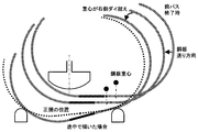
- FIG. 5 schematically shows the situation when the steel plate is fed for the final pass of the second half press forming when the feed amount of the same steel plate as in FIG. 4 is relatively small with respect to the die interval.
- the steel plate In order to send the steel plate to the final pass position, the steel plate is sent toward the steel plate width end side (left side of the figure), but before reaching the final pass position, the center of gravity of the steel plate is the center of the width of the steel plate. Since it exceeds the right side die in the figure on the side, the left side of the steel plate width side is lowered and comes into contact with the left side die.
- the position at which the left end of the steel plate starts to fall and the position in contact with the die also vary depending on the inertial force when feeding the steel plate and the frictional resistance with the die due to the difference in the surface state of the steel plate, so press forming It also causes variation in range.
- FIG. 6 shows the positional relationship between the steel plate, the die and the punch when the steel plate is placed in a state before the final pass (b-th) of the second half press forming.
- L b , L n , W, ⁇ b and ⁇ b shown in the figure are defined as follows.
- L b Molding range (mm) in the final pass of the second half press molding
- L n Molding range in final press molding (mm)
- W Die spacing (mm)
- ⁇ b Steel sheet position shift rate in the final pass of the second half press forming ( ⁇ )
- ⁇ b Die position shift rate in the final pass of the second half press forming ( ⁇ )
- 0 ⁇ ⁇ ⁇ 1, 0 ⁇ ⁇ ⁇ 1, and when ⁇ is 0.5 the center of L b coincides with the center of the punch, and when ⁇ is smaller than 0.5, L b
- the center is shifted to the left side from the center of the punch, and when ⁇ is 0.5, the center between the dies and the center of the punch coincide, and when ⁇ is smaller than 0.5, the center of the die is It will shift to the left from the center of the punch.
- the steel sheet feed amount to the final forming (n-th) after the final pass (b-th) of the second half press forming is ⁇ b
- the steel plate portion formed by the first half press forming comes into contact with the right die in the drawing, that is, the same state as FIG. ⁇ b ⁇ W ⁇ b ⁇ L b + L n (1) This is when the condition is satisfied.
- the influence of the die interval W on the force required for the three-point bending press forming will be examined with reference to FIG.
- the material to be formed (steel plate) is deformed by yielding at the end of the forming range. Therefore, a bending moment necessary for plastic deformation of the material to be formed is present at the end of the forming range.
- the bending moment required for plastic deformation is a value Mf determined by the thickness of the molding material and the deformation resistance, while the force acting on the molding material from the die is the reaction force P 1 and P received from the die. 4 , and a moment obtained by multiplying this by the distance (L 1 and L 4 ) to the deformation point (end of the forming range) acts.
- the main welded steel pipe is preferably expanded using a pipe expanding device.
- the pipe expansion ratio is preferably in the range of 0.5 to 1.2%.
- the end-bending thick steel plate was subjected to three-point bending press forming with a three-point bending press machine having a force of 100MN and variously changing the steel plate feed amount and the die interval, and the outer diameter was 914.4 mm, the length was 12192 mm, The tube was formed into an open tube having a thickness of 31.8 mm, and the amount of misalignment at the butt portion defined in FIG. 8 was measured.
- the punch outer peripheral surface of the three-point bending press molding was R315 mm, and the die outer peripheral surface was R100 mm.
- Table 1 shows the measurement result of the misalignment amount of the butt portion together with the pressing conditions.
- the pressing conditions the number of passes in the second half of the press molding, bending angle theta b per one pass, forming range L b at the final pass of the second half of the press molding, the range L n in the final press-molding, the final late press molding
- the punch shift rate ⁇ b , die shift rate ⁇ b, and die interval W in the pass are shown.
- the bending angle, forming range, punch shift rate and die shift rate per pass are the same as the final pass of the second half press forming, and the first half press forming is the same number of presses as the second half press forming.
- the misalignment amount of the butt portion is 5 mm or less, which is the correctable range, in any condition, but exceeds the correctable range if the condition of the expression (1) is not satisfied. It can be seen that there is a mistaking amount.
- Example 2 In the same manner as in Example 1, a thick steel plate having an API X80 Grade strength, an outer diameter of 914.4 mm, a length of 12192 mm, and a plate thickness of 31.8 mm was subjected to three-point bending press forming into an open pipe for a welded steel pipe. At this time, the number of passes of the second half press molding was changed to 9 and 5 times, and the die interval was changed to 360 mm, 380 mm, 620 mm and 640 mm, and the shift amounts ⁇ b and ⁇ b of the final pass in the second half press molding were further changed under the above conditions. Various changes were made.
- Open pipes for welded steel pipes having various strengths and dimensions were produced in the same manner as in Examples 1 to 3.
- Table 4 shows the strength grade and dimensions of the product, the radius of the tool used as the end bending condition, the working width (end bending range), the bending angle, and the pressing condition.
- the punch shifting rate and die shifting rate were set to 0.5.
- the bending angle per one pass, the molding range, the punch shift rate and the die shift rate are the same as the final pass of the second half press molding.
- the same press times and conditions were used.
- the difference in the welded portion of each oven tube thus obtained was measured and evaluated in the same manner as in Example 1, and the results are also shown in Table 4.
Landscapes
- Engineering & Computer Science (AREA)
- Mechanical Engineering (AREA)
- Bending Of Plates, Rods, And Pipes (AREA)
Abstract
Description
すなわち、本発明は、素材鋼板を、鋼板送り方向に所定の間隔をおいて配設された1対のダイと、前記1対のダイ間で鋼板を押圧するパンチとで3点曲げプレス成形してオープン管とした後、当該オープン管を溶接して鋼管を製造する方法において、前記鋼板の一方の幅端部から幅中央に向かって(ただし、幅中央を残して)前半プレス成形した後、反対側の幅端部から幅中央に向かって(ただし、幅中央を残して)後半プレス成形し、最後に幅中央を最終プレス成形してオープン管とする際、前記後半プレス成形の最終パスで鋼板幅中央側のダイに支持される鋼板を未成形部分とすることを特徴とする溶接鋼管の製造方法である。
記
βb・W<αb・Lb+Ln ・・・(1)
ここで、Lb:後半プレス成形の最終パスにおける成形範囲(mm)
Ln:最終プレス成形における成形範囲(mm)
W:ダイ間隔(mm)
αb:後半プレス成形の最終パスにおける鋼板位置のずらし率(-)
βb:後半プレス成形の最終パスにおけるダイ位置のずらし率(-)
を満たすことを特徴とする。
図1は、鋼板送り方向に所定の間隔をおいて配置され、鋼板を2箇所で支持する1対のダイと、上記鋼板をダイ間で押圧するパンチを有する3点曲げプレス成形機を用いるプレスベンド法により、溶接鋼管の溶接前のオープン管を成形する工程を模式的に示したものである。なお、図1においては、端曲げを付与した鋼板を用いているが、端曲げが付与されていない場合も同様である。
図6に、後半プレス成形の最終パス(b回目)前の状態に鋼板を配置した時の鋼板、ダイおよびパンチの位置関係を示す。ここで、図中に示した、Lb,Ln,W,αbおよびβbはそれぞれ以下のように定義する。
Lb:後半プレス成形の最終パスにおける成形範囲(mm)
Ln:最終プレス成形における成形範囲(mm)
W:ダイ間隔(mm)
αb:後半プレス成形の最終パスにおける鋼板位置のずらし率(-)
βb:後半プレス成形の最終パスにおけるダイ位置のずらし率(-)
ただし、0≦α≦1、0≦β≦1であり、αが0.5のとき、Lbの中心とパンチの中心が一致し、αが0.5より小さい場合には、Lbの中心がパンチの中心より左側にずれることになり、また、βが0.5のとき、ダイ間の中心とパンチの中心が一致し、βが0.5より小さい場合には、ダイの中心がパンチの中心より左側にずれることになる。またこの場合、後半プレス成形の最終パス(b回目)後、最終成形(n回目)への鋼板送り量は、αb×Lb+Ln/2となる。
βb・W<αb・Lb+Ln ・・・(1)
の条件を満たすときである。
ここで、パンチの中心と、ダイ間の中心が一致し、かつ、最終パスにおける鋼板成形範囲の中心が一致する場合、すなわち、α=0.5、β=0.5の場合には、
W<Lb+2Ln ・・・(2)
となり、さらに、Lb=Lnの場合には、すわなち、α=0.5、β=0.5でかつ鋼板送り量が一定の場合には、
W<3Lb ・・・(3)
となり、鋼板送り量は、ダイ間隔Wの1/3以上に設定する必要があることがわかる。
3点曲げ成形においては、成形範囲の端部が降伏することで被成形材(鋼板)は変形するので、成形範囲の端部には、被成形材が塑性変形するのに必要な曲げモーメントが作用しなければならない。ここで、塑性変形に必要な曲げモーメントは、被成形材の厚さや変形抵抗で定まる値Mfであり、一方、被成形材にダイから作用する力は、ダイから受ける反力P1およびP4であり、これに変形点(成形範囲の端部)までの距離(それぞれL1、L4)を乗じたモーメントが作用することになる。そして、P1×L1およびP4×L4のいずれか1以上がMfを上回ったときに、変形を開始する。
しかし、ダイ間隔が狭くなると、距離L1およびL4も小さくなるので、変形に要する反力P1およびP4が大きくなり、プレス機の力量を超えることになり、この場合には成形不可能となる。したがって、3点曲げプレス成形におけるダイ間隔には、プレス機の力量や被成形材の寸法、強度から定まる下限値が存在する。
次いで、上記端曲げを施した厚鋼板を、力量100MNの3点曲げプレス機で、鋼板送り量とダイ間隔を種々に変えて3点曲げプレス成形し、外径914.4mm、長さ12192mm、管厚31.8mmのオープン管に成形し、図8に定義した突合せ部の目違い量を測定した。なお、上記3点曲げプレス成形のパンチ外周面はR315mm、ダイ外周面はR100mmのものを用いた。
また、表1中の備考欄に記載された「力量不足」は、ダイ間隔が狭く、プレス機の力量不足でプレス成形できなかったことを示している。一方、プレス力量が能力範囲内であった条件については、5本ずつオープン管を成形したときの目違い量の最小値と最大値を示した。
また、表1中に示した突合せ部の目違い量の評価は、本実施例に用いた溶接鋼管の製造ラインに設置された仮付溶接時の拘束機の修正能力から、目違い量が5mm以下を合格(○)、5mm超えを不合格(×)と判定した。

斯くして得られた各オーブン管の溶接部の目違い量を、実施例1と同様にして測定して評価し、その結果を表2に示した。

斯くして得られた各オーブン管の溶接部の目違い量を、実施例1と同様にして測定して評価し、その結果を表3に併記した。

斯くして得られた各オーブン管の溶接部の目違い量を、実施例1と同様にして測定して評価し、その結果を表4に併記した。

Claims (2)
- 素材鋼板を、鋼板送り方向に所定の間隔をおいて配設された1対のダイと、前記1対のダイ間で鋼板を押圧するパンチとで3点曲げプレス成形してオープン管とした後、当該オープン管を溶接して鋼管を製造する方法において、
前記鋼板の一方の幅端部から幅中央に向かって(ただし、幅中央を残して)複数回の前半プレス成形した後、反対側の幅端部から幅中央に向かって(ただし、幅中央を残して)複数回の後半プレス成形し、最後に幅中央を最終プレス成形してオープン管とする際、
前記後半プレス成形の最終パスで鋼板幅中央側のダイに支持される鋼板を未成形部分とすることを特徴とする溶接鋼管の製造方法。 - 前記後半プレス成形の最終パスが、下記(1)式を満たすことを特徴とする請求項1に記載の溶接鋼管の製造方法。
記
βb・W<αb・Lb+Ln ・・・(1)
ここで、Lb:後半プレス成形の最終パスにおける成形範囲(mm)
Ln:最終プレス成形における成形範囲(mm)
W:ダイ間隔(mm)
αb:後半プレス成形の最終パスにおける鋼板位置のずらし率(-)
βb:後半プレス成形の最終パスにおけるダイ位置のずらし率(-)
Priority Applications (5)
| Application Number | Priority Date | Filing Date | Title |
|---|---|---|---|
| CN201380076724.8A CN105246608B (zh) | 2013-05-29 | 2013-05-29 | 焊接钢管的制造方法 |
| JP2015519536A JP6070967B2 (ja) | 2013-05-29 | 2013-05-29 | 溶接鋼管の製造方法 |
| PCT/JP2013/064852 WO2014192091A1 (ja) | 2013-05-29 | 2013-05-29 | 溶接鋼管の製造方法 |
| EP13885748.7A EP3006128B1 (en) | 2013-05-29 | 2013-05-29 | Method of manufacturing a welded steel pipe |
| RU2015155550A RU2621747C1 (ru) | 2013-05-29 | 2013-05-29 | Способ получения сварной стальной трубы |
Applications Claiming Priority (1)
| Application Number | Priority Date | Filing Date | Title |
|---|---|---|---|
| PCT/JP2013/064852 WO2014192091A1 (ja) | 2013-05-29 | 2013-05-29 | 溶接鋼管の製造方法 |
Publications (1)
| Publication Number | Publication Date |
|---|---|
| WO2014192091A1 true WO2014192091A1 (ja) | 2014-12-04 |
Family
ID=51988165
Family Applications (1)
| Application Number | Title | Priority Date | Filing Date |
|---|---|---|---|
| PCT/JP2013/064852 Ceased WO2014192091A1 (ja) | 2013-05-29 | 2013-05-29 | 溶接鋼管の製造方法 |
Country Status (5)
| Country | Link |
|---|---|
| EP (1) | EP3006128B1 (ja) |
| JP (1) | JP6070967B2 (ja) |
| CN (1) | CN105246608B (ja) |
| RU (1) | RU2621747C1 (ja) |
| WO (1) | WO2014192091A1 (ja) |
Cited By (1)
| Publication number | Priority date | Publication date | Assignee | Title |
|---|---|---|---|---|
| DE102015210259A1 (de) * | 2015-06-03 | 2016-12-08 | Sms Group Gmbh | Verfahren zum Herstellen von Schlitzrohren aus Blechtafeln |
Families Citing this family (8)
| Publication number | Priority date | Publication date | Assignee | Title |
|---|---|---|---|---|
| JP6709638B2 (ja) | 2016-03-10 | 2020-06-17 | 日立造船株式会社 | 鋼管構造体における鋼管と継手との溶接方法 |
| JP6566231B1 (ja) * | 2018-03-30 | 2019-08-28 | Jfeスチール株式会社 | 鋼板の端曲げ方法および装置並びに鋼管の製造方法および設備 |
| JP6791397B2 (ja) * | 2018-09-14 | 2020-11-25 | Jfeスチール株式会社 | 鋼管の製造方法及びプレス金型 |
| CN109500118B (zh) * | 2018-12-26 | 2023-06-09 | 重庆龙煜精密铜管有限公司 | 一种防跳车游动芯头及铜管缩径拉拔防跳车方法 |
| CN112024723A (zh) * | 2020-08-21 | 2020-12-04 | 江苏恒高电气制造有限公司 | 一种gil小角度壳体弯曲装置 |
| CN112659563A (zh) * | 2020-11-27 | 2021-04-16 | 常州安一智能科技有限公司 | 圆桶滤网热压拼接设备及其工作方法 |
| DE102020215088A1 (de) * | 2020-12-01 | 2022-06-02 | Sms Group Gmbh | Verfahren zur Herstellung von Schlitzrohren |
| CN114570784B (zh) * | 2021-12-24 | 2022-12-06 | 钢一控股集团有限公司 | 一种大口径不锈钢管的成型装置 |
Citations (7)
| Publication number | Priority date | Publication date | Assignee | Title |
|---|---|---|---|---|
| JPH10166059A (ja) * | 1996-12-06 | 1998-06-23 | Mitsubishi Heavy Ind Ltd | 板の曲げ加工方法 |
| JPH11129031A (ja) | 1997-10-29 | 1999-05-18 | Mitsubishi Heavy Ind Ltd | プレス成形金型 |
| JP2004082219A (ja) * | 2002-07-15 | 2004-03-18 | Sms Meer Gmbh | 金属板から管を製造するための装置 |
| JP2005324255A (ja) | 2005-06-17 | 2005-11-24 | Nakajima Steel Pipe Co Ltd | 丸鋼管の製造方法 |
| JP2007090406A (ja) | 2005-09-30 | 2007-04-12 | Nakajima Steel Pipe Co Ltd | 丸鋼管の製造設備 |
| JP2012170977A (ja) * | 2011-02-21 | 2012-09-10 | Jfe Steel Corp | 鋼管の製造方法 |
| JP2012250285A (ja) * | 2011-05-31 | 2012-12-20 | Sms Meer Gmbh | 板材からスリット管を製造する方法及び装置 |
Family Cites Families (9)
| Publication number | Priority date | Publication date | Assignee | Title |
|---|---|---|---|---|
| BE525415A (ja) * | ||||
| JPS5118253A (ja) * | 1974-08-06 | 1976-02-13 | Osaka Tetsuen Kikai Kk | Kokanseikeiyopuresusochi |
| FI74414C (fi) * | 1980-08-18 | 1988-02-08 | Sl Tuotanto Oy | Anordning foer framstaellning av ett metallroer. |
| RU2090281C1 (ru) * | 1996-08-05 | 1997-09-20 | Акционерное общество открытого типа "УралЛУКтрубмаш" | Способ изготовления сварных стальных труб |
| JP2003251406A (ja) * | 2002-02-27 | 2003-09-09 | Jfe Steel Kk | 溶接管の製造方法および設備列 |
| WO2009023973A1 (de) * | 2007-08-21 | 2009-02-26 | Soutec Soudronic Ag | Vorrichtung und verfahren zum formen eines rohres aus einem blech |
| KR101257360B1 (ko) * | 2008-03-31 | 2013-04-23 | 제이에프이 스틸 가부시키가이샤 | 고밀도 에너지 빔으로 접합한 용접 강관 및 그의 제조 방법 |
| DE102008027807B4 (de) * | 2008-06-06 | 2011-05-12 | Eisenbau Krämer mbH | Verfahren zum Herstellen eines großen Stahlrohres |
| WO2012092909A1 (de) * | 2011-01-07 | 2012-07-12 | Technische Universität Dortmund | Verfahren zum inkrementellen umformen von blechstrukturen, insbesondere zum umformen von rohren oder dgl. |
-
2013
- 2013-05-29 CN CN201380076724.8A patent/CN105246608B/zh active Active
- 2013-05-29 WO PCT/JP2013/064852 patent/WO2014192091A1/ja not_active Ceased
- 2013-05-29 RU RU2015155550A patent/RU2621747C1/ru active
- 2013-05-29 EP EP13885748.7A patent/EP3006128B1/en active Active
- 2013-05-29 JP JP2015519536A patent/JP6070967B2/ja active Active
Patent Citations (7)
| Publication number | Priority date | Publication date | Assignee | Title |
|---|---|---|---|---|
| JPH10166059A (ja) * | 1996-12-06 | 1998-06-23 | Mitsubishi Heavy Ind Ltd | 板の曲げ加工方法 |
| JPH11129031A (ja) | 1997-10-29 | 1999-05-18 | Mitsubishi Heavy Ind Ltd | プレス成形金型 |
| JP2004082219A (ja) * | 2002-07-15 | 2004-03-18 | Sms Meer Gmbh | 金属板から管を製造するための装置 |
| JP2005324255A (ja) | 2005-06-17 | 2005-11-24 | Nakajima Steel Pipe Co Ltd | 丸鋼管の製造方法 |
| JP2007090406A (ja) | 2005-09-30 | 2007-04-12 | Nakajima Steel Pipe Co Ltd | 丸鋼管の製造設備 |
| JP2012170977A (ja) * | 2011-02-21 | 2012-09-10 | Jfe Steel Corp | 鋼管の製造方法 |
| JP2012250285A (ja) * | 2011-05-31 | 2012-12-20 | Sms Meer Gmbh | 板材からスリット管を製造する方法及び装置 |
Cited By (3)
| Publication number | Priority date | Publication date | Assignee | Title |
|---|---|---|---|---|
| DE102015210259A1 (de) * | 2015-06-03 | 2016-12-08 | Sms Group Gmbh | Verfahren zum Herstellen von Schlitzrohren aus Blechtafeln |
| DE102015210259B4 (de) * | 2015-06-03 | 2016-12-15 | Sms Group Gmbh | Verfahren zum Herstellen von Schlitzrohren aus Blechtafeln |
| US11097326B2 (en) | 2015-06-03 | 2021-08-24 | Sms Group Gmbh | Method for producing open-seam pipes from sheet metal panels |
Also Published As
| Publication number | Publication date |
|---|---|
| EP3006128A1 (en) | 2016-04-13 |
| EP3006128A4 (en) | 2016-06-29 |
| CN105246608B (zh) | 2018-01-02 |
| CN105246608A (zh) | 2016-01-13 |
| JP6070967B2 (ja) | 2017-02-01 |
| EP3006128B1 (en) | 2018-10-24 |
| JPWO2014192091A1 (ja) | 2017-02-23 |
| RU2621747C1 (ru) | 2017-06-07 |
Similar Documents
| Publication | Publication Date | Title |
|---|---|---|
| JP6070967B2 (ja) | 溶接鋼管の製造方法 | |
| EP3127624B1 (en) | Bending-press forming tool | |
| CN110461488B (zh) | 冲压模具及钢管的制造方法 | |
| CA2967914C (en) | Method of producing steel pipe and press die used for same | |
| JP2012170977A (ja) | 鋼管の製造方法 | |
| KR910009151B1 (ko) | 얇은 두께의 금속파이프를 제조하는 방법 | |
| CN104271279B (zh) | 钢管的制造方法 | |
| JP6566231B1 (ja) | 鋼板の端曲げ方法および装置並びに鋼管の製造方法および設備 | |
| CN105246609B (zh) | 钢管的冲压成形方法及钢管的制造方法 | |
| JP6566232B1 (ja) | 鋼板の端曲げ方法および装置並びに鋼管の製造方法および設備 | |
| KR102425607B1 (ko) | 강관의 제조 방법 및 프레스 금형 | |
| JP2018015796A (ja) | 直線形鋼矢板の曲がり矯正方法及び曲がり矯正装置 | |
| JP2019177398A (ja) | 鋼板の端曲げ方法および装置並びに鋼管の製造方法および設備 | |
| JP2015167973A (ja) | 厚肉電縫管の製造方法 |
Legal Events
| Date | Code | Title | Description |
|---|---|---|---|
| 121 | Ep: the epo has been informed by wipo that ep was designated in this application |
Ref document number: 13885748 Country of ref document: EP Kind code of ref document: A1 |
|
| ENP | Entry into the national phase |
Ref document number: 2015519536 Country of ref document: JP Kind code of ref document: A |
|
| WWE | Wipo information: entry into national phase |
Ref document number: 2013885748 Country of ref document: EP |
|
| WWE | Wipo information: entry into national phase |
Ref document number: P1584/2015 Country of ref document: AE |
|
| NENP | Non-entry into the national phase |
Ref country code: DE |
|
| ENP | Entry into the national phase |
Ref document number: 2015155550 Country of ref document: RU Kind code of ref document: A |