WO2014192350A1 - 回転電機およびその製造方法 - Google Patents
回転電機およびその製造方法 Download PDFInfo
- Publication number
- WO2014192350A1 WO2014192350A1 PCT/JP2014/055375 JP2014055375W WO2014192350A1 WO 2014192350 A1 WO2014192350 A1 WO 2014192350A1 JP 2014055375 W JP2014055375 W JP 2014055375W WO 2014192350 A1 WO2014192350 A1 WO 2014192350A1
- Authority
- WO
- WIPO (PCT)
- Prior art keywords
- slot
- stator
- coil
- electrical machine
- rotating electrical
- Prior art date
- Legal status (The legal status is an assumption and is not a legal conclusion. Google has not performed a legal analysis and makes no representation as to the accuracy of the status listed.)
- Ceased
Links
Images











Classifications
-
- H—ELECTRICITY
- H02—GENERATION; CONVERSION OR DISTRIBUTION OF ELECTRIC POWER
- H02K—DYNAMO-ELECTRIC MACHINES
- H02K15/00—Processes or apparatus specially adapted for manufacturing, assembling, maintaining or repairing of dynamo-electric machines
- H02K15/08—Forming windings by laying conductors into or around core parts
- H02K15/085—Forming windings by laying conductors into or around core parts by laying conductors into slotted stators
-
- H—ELECTRICITY
- H02—GENERATION; CONVERSION OR DISTRIBUTION OF ELECTRIC POWER
- H02K—DYNAMO-ELECTRIC MACHINES
- H02K1/00—Details of the magnetic circuit
- H02K1/06—Details of the magnetic circuit characterised by the shape, form or construction
- H02K1/12—Stationary parts of the magnetic circuit
- H02K1/16—Stator cores with slots for windings
- H02K1/165—Shape, form or location of the slots
-
- H—ELECTRICITY
- H02—GENERATION; CONVERSION OR DISTRIBUTION OF ELECTRIC POWER
- H02K—DYNAMO-ELECTRIC MACHINES
- H02K15/00—Processes or apparatus specially adapted for manufacturing, assembling, maintaining or repairing of dynamo-electric machines
- H02K15/04—Processes or apparatus specially adapted for manufacturing, assembling, maintaining or repairing of dynamo-electric machines of windings prior to their mounting into the machines
-
- H—ELECTRICITY
- H02—GENERATION; CONVERSION OR DISTRIBUTION OF ELECTRIC POWER
- H02K—DYNAMO-ELECTRIC MACHINES
- H02K3/00—Details of windings
- H02K3/04—Windings characterised by the conductor shape, form or construction, e.g. with bar conductors
- H02K3/12—Windings characterised by the conductor shape, form or construction, e.g. with bar conductors arranged in slots
-
- H—ELECTRICITY
- H02—GENERATION; CONVERSION OR DISTRIBUTION OF ELECTRIC POWER
- H02K—DYNAMO-ELECTRIC MACHINES
- H02K2213/00—Specific aspects, not otherwise provided for and not covered by codes H02K2201/00 - H02K2211/00
- H02K2213/03—Machines characterised by numerical values, ranges, mathematical expressions or similar information
Definitions
- the present invention relates to a rotating electrical machine and a method for manufacturing the same, and particularly relates to a stator of the rotating electrical machine, and aims to achieve high efficiency and high output as a rotating electrical machine and to improve its assemblability.
- Patent Document 1 can be cited as a background technique for achieving high efficiency and high output of a rotating electrical machine.
- this document 1 by providing a width adjusting portion that narrows the circumferential width of the slots between the stator teeth toward the inner side in the radial direction, the difference in magnetic resistance in the radial direction of the teeth is reduced, and the performance as a rotating electrical machine is improved. I am trying.
- the stator coil is formed in a substantially U shape having two straight portions and a connecting portion connecting the straight portions, and this stator coil.
- the straight portion After forming the cross section of the straight portion into a shape along the width adjusting portion and a shape along both ends in the radial direction along a direction perpendicular to the radial direction, the straight portion is inserted into the slot from the axial direction. Thereby, the clearance gap between a stator coil and a slot can be narrowed, and the space factor of a stator can be improved.
- the stator coil of Patent Document 1 is formed by connecting a plurality of unit conductors with a unit formed of a substantially U-shaped conductor having two straight portions and a connecting portion connecting the straight portions.
- the number of conductors since there are two straight portions, the number of conductors requires (number of slots ⁇ number of turns) / 2 stators.
- the number of conductors constituting the stator coil is increased, and the assemblability of the stator is deteriorated.
- the number of connection points connecting the conductors also increases. This also reduces the reliability of the stator. Furthermore, the stator becomes larger.
- the conductor when assembling the stator coil to the stator core, the conductor is moved substantially parallel to the axial direction of the center axis of the stator, so that the linear portion is inserted into the slot.
- the conductor to be inserted later needs to be inserted and arranged in a state of straddling the initially inserted conductor.
- the present invention has been made in order to solve the above-described problems, and an object of the present invention is to obtain a stator for a rotating electrical machine having high efficiency, high output, and excellent assemblability, and a method for manufacturing the same. .
- the rotating electrical machine includes a rotor and a stator disposed on the outer peripheral side of the rotor,
- the stator includes a stator core and a stator coil
- the stator core includes an inner ring core that includes a plurality of teeth that extend in the radial direction and are spaced apart from each other in the circumferential direction and a connecting portion that connects the inner peripheral portions of the plurality of teeth, and a plurality of stator cores that are formed in a cylindrical shape. It has an outer ring core that can be joined to the outer peripheral surface of the teeth,
- the slot formed between adjacent teeth of the stator core has a circumferential width at its inner circumferential portion so that the circumferential width of the teeth is substantially constant along the radial direction.
- the stator coil is formed by connecting a plurality of conductor coils formed by forming a conductive wire.
- the conductor coil includes a plurality of slot storage portions arranged inside the slots and a plurality of slot stores outside the slots. And a plurality of coil end portions connecting the portions.
- the manufacturing method of the rotating electrical machine includes an insertion arrangement step of arranging a plurality of conductor coils in the slots of the inner ring core by inserting a slot housing portion between the teeth from the radially outer side of the inner ring core, the conductor coil Are provided with a core coupling step in which the outer ring core is bonded and assembled to the outer peripheral surface of the inner ring core in which is inserted and arranged, and a bonding step in which the end portions of the conductor coils are bonded to form a stator coil.
- the circumferential width of the inner circumferential portion of the slot is smaller than the circumferential width of the outer circumferential portion so that the circumferential width of the teeth is substantially constant along the radial direction.
- the difference in the magnetic resistance in the radial direction of the teeth is reduced, and the slot accommodating portion of the conductor coil can be inserted and arranged in the slot from the radially outer side of the inner ring core.
- FIG. 1 It is a perspective view which shows the stator 1 of the rotary electric machine by Embodiment 1 of this invention. It is a perspective view which shows the stator core 2 by Embodiment 1 of this invention. It is principal part sectional drawing of the stator core 2 by Embodiment 1 of this invention. It is sectional drawing of the conductor coil 11 by Embodiment 1 of this invention. It is a principal part perspective view of the conductor coil 11 by Embodiment 1 of this invention. It is principal part sectional drawing of the conductor coil 11 by Embodiment 1 of this invention. It is a principal part top view of the stator 1 by Embodiment 1 of this invention. It is principal part sectional drawing explaining the assembly method of the stator 1 by Embodiment 1 of this invention.
- FIG. 12 is a cross-sectional view taken along line AA in FIG.
- FIG. 12 is a sectional view taken along line BB in FIG.
- FIG. 12 is a sectional view taken along line CC in FIG. 11.
- FIG. 21 is a sectional view taken along line AA in FIG. 20.
- FIG. 21 is a sectional view taken along line BB in FIG. 20.
- FIG. 1 shows the stator 1
- FIG. 2 shows the stator core 2
- FIG. 3 shows a cross section of the main part of the stator core 2
- the conductor coil. 11 showing the cross section of FIG. 11,
- FIG. 5 showing the main part of the conductor coil 11
- FIG. 6 showing the cross section of the main part of the conductor coil 11
- FIG. 7 showing the upper surface of the main part of the stator 1.
- the rotor is located in the center of the rotating electrical machine, and the stator 1 is disposed on the outer peripheral side of the rotor.
- the stator 1 includes an annular stator core 2 having a plurality of slots 5 arranged in the circumferential direction, and is distributed to the stator core 2 through the slots 5.
- Two sets of three-phase (U-phase, V-phase, W-phase) Y-connected stator coils 10 wound by a winding method are provided.
- the stator core 2 is fixed to an inner ring core 3 including a plurality of teeth 6 arranged at predetermined substantially constant intervals in the circumferential direction, and a connecting portion 7 that connects inner peripheral portions of the teeth 6. It is comprised from the outer ring
- the inner ring core 3 and the outer ring core 4 are separate parts, and the outer ring core 4 is assembled to the outer peripheral surface of the inner ring core 3 to form a slot 5 surrounded by the teeth 6 adjacent to the connecting portion 7 and the outer ring core 4. Is done.
- the slot 5 is formed so that a ⁇ b ⁇ c.
- a specific shape of the slot 5 will be described with reference to FIGS.
- a step 8 is provided in the middle, and the circumferential width a of the inner periphery of the slot 5 is narrower than the circumferential width b of the outer periphery.
- a taper 9 is provided to gradually narrow the circumferential width from the middle of the slot 5 toward the inner circumferential side from the middle of the slot 5, and the circumferential width a of the inner circumferential portion of the slot 5 is set to the outer circumference. It is narrower than the circumferential width b of the part.
- a taper 9 is provided over the entire side surface of the slot 5.
- the number of slots 5 and teeth 6 is 48.
- the stator coil 10 is formed by connecting the coil ends 15 of a plurality of conductor coils 11 inserted into the slot 5 by welding.
- the conductor coil 11 is formed by molding one conductor wire composed of a conductor portion 17 and an insulating film 18 that covers the surface of the conductor portion 17 by baking enamel. It comprises three or more slot storage portions 12 that are inserted through and a plurality of coil end portions 13 that connect the slot storage portions 12.
- the plurality of slot accommodating portions 12 are arranged in the slot 5 so as to be arranged in the radial direction. At this time, since the circumferential width a of the inner peripheral portion of the slot 5 is narrower than the circumferential width b of the outer peripheral portion, the slot accommodating portions 12 having at least two types of cross-sectional shapes are placed in the same slot. Mix. And, as shown in FIG. 6, by making the circumferential width of the slot accommodating portion 12a disposed on the inner peripheral side of the slot 5 smaller than the circumferential width of the slot accommodating portion 12b disposed on the outer peripheral side, The space between the slot 5 and the slot storage portion 12 can be narrowed to increase the space factor of the stator 1.
- FIG. 6A shows a conductor coil 11 having a rectangular cross section that is inserted through the slot 5 in different directions.
- two slot storage portions 12 a that are first conductor coils formed so that the cross-sectional shape thereof has a circumferential width ⁇ a radial width are arranged, and on the outer peripheral side of the slot 5
- Two slot accommodating portions 12b which are second conductor coils arranged on the outer peripheral side of the first conductor coil formed so that the cross-sectional shape thereof has a circumferential width ⁇ a radial width, are arranged.
- FIG. 6B shows a conductor coil 11 having a rectangular cross-sectional shape and a conductor coil 11 having a circular cross-sectional shape that are inserted through the slot 5.
- Two slot storage portions 12a which are first conductor coils having a flat cross-sectional shape, are arranged on the inner peripheral side of the slot 5, and a second conductor having a circular cross-sectional shape is provided on the outer peripheral side.
- Two slot accommodating portions 12b which are coils, are arranged.
- a slot accommodating portion 12a which is a first conductor coil having a circular cross-sectional shape, is disposed on the inner peripheral side of the slot 5, and a slot accommodating portion 12b, which is a second conductor coil having a rectangular cross-sectional shape, is disposed on the outer peripheral side.
- the slot accommodating portions 12a and 12b having a circular cross-sectional shape with different diameters may be arranged.
- the two slot accommodating portions 12 connected via a certain coil end portion 13 are arranged in different slots 5, and the radial positions in the slots 5 are also different from each other.
- the coil end portion 13 has a substantially arc shape, but is provided with a lane change portion 14 for absorbing the difference in radial position.
- the lane change portion 14 is formed and formed in advance at the manufacturing stage of the conductor coil 11.
- the number of slot accommodating portions 12 arranged in the radial direction in the same slot 5 is four, and the cross-sectional shapes thereof are two types.
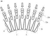
- the slot accommodating portion 12 is inserted into the gap between the teeth 6 of the inner ring core 3 from the radially outer side of the inner ring core 3 (insertion placement step).
- a necessary number of conductor coils 11 are formed in a substantially cylindrical shape on a jig having a slightly larger diameter than the inner ring core 3 in advance, and this is formed in a radial direction as shown in FIG.
- the conductor coil 11 is once formed in a straight line and is inserted directly into the slot 5 of the inner ring core 3 sequentially from its end so as to be wound. You may do it.
- an insulating paper 19 is inserted and disposed so as to cover the peripheral portions of the teeth 6 and the connecting portion 7, and the slot accommodating portion 12 and the inner ring are arranged. Insulation with the core 3 is ensured.
- the outer ring core 4 is joined and assembled to the outer peripheral surface of the inner ring core 3 in which the conductor coil 11 is inserted and arranged.
- the coil end portions 15 of the conductor coil 11 are joined by, for example, TIG welding, resistance welding, or the like (joining process).
- the joining portion is constituted by collecting and joining two coil end portions 15 at one place. However, since the neutral point needs to connect three points of UVW, three coil end portions 15 are gathered and joined in one place.
- an intermediate part (terminal or the like) for connecting to another device is joined separately, or nothing is done at this stage, and the next process is performed. move on.
- the terminal may be joined to the resin via a relay part inserted or outsert. May be.
- the assembly process is simplified and the assemblability is improved.
- a rotary electric machine can be driven by a double system.
- the ripple current can be lowered by shifting the phase of each phase and increasing the order of the harmonics.
- two independent drive circuits can be provided by using two inverters (not shown) for driving and controlling the rotating electrical machine, and redundancy can be obtained.
- the slot 5 is formed so that the circumferential width a of the inner peripheral portion thereof is smaller than the circumferential width b of the outer peripheral portion thereof.
- the circumferential width can be made substantially constant along the radial direction, the difference in magnetic resistance in the radial direction of the teeth 6 is reduced, and the performance as a rotating electrical machine is improved.
- a first conductor coil constituting the slot accommodating portion 12 disposed on the inner peripheral side of the slot 5 and a second conductor coil constituting the slot accommodating portion 12 disposed on the outer peripheral side of the slot 5, Each having different cross-sectional shapes in accordance with the shape of the slot 5, and the space factor of the slot accommodating portion 12 in the slot 5 is increased. The resistance is reduced and the efficiency and output of the rotating electrical machine are improved.
- each conductor coil 11 does not need to form a partial cross-section of the conductor in accordance with the shape of the slot 5, and the workability when forming the conductor coil 11 is improved.
- the coil end portion 13 of the first conductor coil disposed on the inner peripheral side of the slot 5 also has a cross section that is more than that of the coil end portion 13 of the second conductor coil disposed on the outer peripheral side of the slot 5.
- the circumferential width is small.
- the area that can be occupied by the coil end portion 13 is naturally narrower on the inner peripheral side than on the outer peripheral side. Therefore, the coil end portion 13 of both the first conductor coil and the second conductor coil can be configured without difficulty. As a result, the resistance of the stator coil 10 is reduced, and the efficiency and output of the rotating electrical machine are improved.
- the slot accommodating portion 12 of the conductor coil 11 is inserted and arranged in the slot 5 from the radially outer side of the inner ring core 3, but the circumferential direction of the inner peripheral portion of the slot 5 Since the circumferential width b of the outer peripheral portion is made larger than the width a, the outer peripheral side insertion port when the slot storage portion 12 is inserted becomes wider. Thereby, the insertion operation of the conductor coil 11 into the inner ring core 3 is facilitated, and the assemblability of the stator 1 is improved.
- the rigidity of the stator core 2 is increased. Therefore, since the deformation of the core can be prevented when the conductor coil 11 is inserted and when the outer ring core 4 is assembled to the inner ring core 3, the assemblability of the stator 1 is improved. Further, since the rigidity of the stator core 2 is increased, vibration and noise of the rotating electrical machine can be suppressed, and the performance, quality, and reliability of the rotating electrical machine are improved.
- the lane change portion 14 is formed in advance in the coil end portion 13, when the conductor coil 11 is inserted into the gap between the teeth 6, interference between the conductor coils 11 can be prevented. Assemblability is improved. Furthermore, since the conductor coils 11 are in contact with each other and problems such as damage to the insulating film 18 can be suppressed, the quality of the rotating electrical machine is improved.
- the number of slots per phase of each pole of the stator 1 is 2, it is possible to drive in a double system, and the ripple current can be reduced. Thereby, the cogging torque of the rotating electrical machine is reduced and the quality is stabilized. Further, by providing two inverters as drive power supplies, redundancy can be obtained in the rotating electrical machine. Thereby, the reliability of the rotating electrical machine is improved. Further, by parallelizing the drive circuits, the current flowing through each circuit can be reduced. This makes it possible to reduce the loss of the rotating electrical machine and reduce the performance of the rotating electrical machine, especially in the case of a small capacity machine, where the same size as the lower limit is adopted for the conductor to withstand mechanical stress such as winding work. , Improve reliability.
- the stator 1 is shown as a double three-phase having two sets of three-phase Y connections.
- the present invention is not limited to this, and this may be a single phase or three or more phases.
- the invention can be applied in the same manner and has the same effect.
- the connection may be a ⁇ connection.
- the number of slots of the stator 1 is shown as 48, it is not limited to this.
- the number of the slot accommodating parts 12 arranged in the same slot 5 is four and the cross-sectional shapes of the slot accommodating parts 12 inserted through the same slot 5 are shown as two types, it is not limited to this.
- FIG. 10 showing a cross section of the main part of the conductor coil 11
- FIG. 11 showing the main part of the conductor coil 11.
- components that are substantially the same as those of the first embodiment are given the same reference numerals, and descriptions thereof are omitted.
- the second embodiment is different from the first embodiment in that the cross-sectional shape of the slot accommodating portion 12 of the conductor coil 11 is formed in a shape different from the cross-sectional shape of the original conductive wire, and this portion will be mainly described below.
- FIG. 10A shows a case in which the slot accommodating portion 12 of the conductor coil 11 having a circular cross-sectional shape is formed on two sides.
- Two slot accommodating portions 12a are arranged on the inner peripheral side of the slot 5 in a direction in which the cross-sectional shape is circumferential width ⁇ radial width, and the cross-sectional shape is arranged in the circumferential direction on the outer peripheral side of the slot 5.
- Two slot storage portions 12b are arranged in the direction of width ⁇ diameter width.
- FIG. 10B shows a case in which the slot accommodating portion 12 of the conductor coil 11 having a circular cross-sectional shape is formed on four sides.
- the slot accommodating portion 12 is formed such that both ends in the circumferential direction are shaped in accordance with the circumferential width shape of the slot 5 by using an upper die 20 and a lower die 21 that match the shape of the slot 5.
- the both ends in the radial direction are formed in a shape along the direction perpendicular to the radial direction.
- FIG. 11 the external appearance of the conductor coil 11 of this Embodiment 2 is shown.
- the slot accommodating portion 12 is formed so that its cross-sectional shape is substantially trapezoidal. 12 is a sectional view taken along line AA in FIG. 11, FIG. 13 is a sectional view taken along line BB in FIG. 11, and FIG. 14 is a sectional view taken along line CC in FIG.
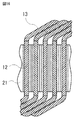
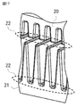
- FIGS. 15A-15B a portion corresponding to the slot accommodating portion 12 of the conductor coil 11 is set on the lower mold 21 (FIG. 15A). Thereafter, the upper mold 20 is set on the lower mold 21 and press-molded (FIG. 15B). At this time, since only the slot accommodating portion 12 is molded, the coil end portion 13 is protruded outside the molds 20 and 21 as shown in FIG.
- tapered or arc-shaped reliefs 22 are provided at axial ends of the upper mold 20 and the lower mold 21.
- an arcuate or tapered relay portion 16 (FIG. 11) is formed at the boundary between the slot accommodating portion 12 to be molded and the coil end portion 13 that is not subject to molding processing.
- the formed part and the non-formed part, that is, the slot accommodating part 12 and the coil end part 13 are smoothly connected via the relay part 16 to prevent the insulation film from being damaged due to a sudden change in cross section.
- the cross-sectional shape of the molded slot accommodating portion 12 will be described with reference to FIGS. 10 and 18.
- the slot accommodating portion 12 is set at the same time and molded together.
- the degree of adhesion between the slot storage portions 12 is increased, so that the separation from the molds 20 and 21 and misalignment that may occur due to an impact in the manufacturing process can be suppressed.
- the contact area between the slot storage portions 12 increases, the coil heat dissipation effect of the rotating electrical machine is also improved.
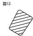
- the slot accommodating portion 12 is formed in a substantially trapezoidal shape, the slot accommodating portion 12 is subjected to reaction forces from four directions by the upper mold 20 and the lower mold 21 or the adjacent slot accommodating portions 12 at the time of molding. Receive. Thereby, the cross section is formed into a substantially trapezoidal shape by spreading to the four corners. At this time, not only the conductor portion 17 of the conductive wire but also the insulating coating 18 is spread over the four corners, and as shown in FIG. 18, the thickness of the insulating coating at the corner of the cross section is formed to be thicker than the other portions.
- FIG. 18 shows the cross-sectional shape of the slot accommodating portion 12 inserted and arranged in the innermost circumference of the slot 5 in FIG. 10, but the same molding is performed for other cross-sections.
- the slot accommodating portion 12 is press-molded into a shape along the slot shape using the molds 20 and 21, and therefore, between the slot accommodating portion 12 and the slot 5.
- the space factor of the slot accommodating portion 12 in the slot 5, and thus the space factor of the stator 1 can be increased.
- the resistance of the stator coil 10 is reduced, and the efficiency and output of the rotating electrical machine are improved.
- a coil end portion 13 that is not molded and maintains the original conductor shape is configured on the extension of the slot accommodating portion 12.
- the molded slot accommodating portion 12 fits in the slot 5 without a gap and is securely held by the stator core 2, so that the stator coil 10 is inserted and arranged in the inner ring core 3, and then axially moved. Can be suppressed, and the assemblability of the stator 1 is improved.
- the relay part 16 is formed at the boundary between the molded slot storage part 12 and the coil end part 13, and both are smoothly connected. Thereby, the elongation and breakage of the insulating film 18 due to a sudden change in the cross section can be prevented, and the reliability of the rotating electrical machine is improved.
- the insulating film 18 at the cross-sectional corner is formed thicker than the other parts by this molding, the withstand voltage of the stator coil 10 is improved, and the quality and reliability of the rotating electrical machine are improved.
- the slot accommodating portion 12 is formed, a plurality of the portions are simultaneously formed at the same time, so that the cross-sectional shape can be formed with high accuracy and can be made closer to the slot shape. Thereby, the space factor of the stator 1 can be raised, the resistance of the stator coil 10 is reduced, and the efficiency and output of the rotating electrical machine are improved.
- the stator core 2 can be assembled at a low cost and the assemblability is improved. Moreover, since the close contact degree of the slot accommodating part 12 increases and position shift can be suppressed, the assembly property of the stator 1 improves. Furthermore, since the contact area of the slot accommodating part 12 increases, the heat dissipation performance of the stator coil 10 is improved, and the performance, quality, and reliability of the rotating electrical machine are improved.
- the part to be molded is limited to only the slot housing portion 12, the molded portion can be protected by the stator core 2 after the stator 1 is assembled. Thereby, deterioration of the forming part due to disturbance can be prevented, and the reliability of the rotating electrical machine can be ensured.
- the conductor coil 11 is shown as a case where a conductor having a circular cross section is formed.
- the present invention is not limited to this.
- the present invention is the same even if the cross section is a flat angle. The same effect can be achieved.
- the number of the slot accommodating portions 12 to be simultaneously formed at the time of forming the conductor coil 11 is four, but the present invention is not limited to this.
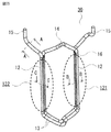
- Embodiment 3 The structure of the stator of the rotating electrical machine according to the third embodiment of the present invention will be described with reference to FIG. 19 showing the stator 1 and FIG. 20 showing the turtle shell coil 30 which is a conductor coil.
- the conductor coil is a turtle shell coil 30 formed by overlapping and forming a conductive wire in a substantially hexagonal shape, and this portion will be mainly described below.
- FIG. 19 shows the stator 1 configured by connecting the coil end portions 15 of the plurality of turtle shell coils 30 inserted into the slots 5 by welding.
- the turtle shell coil 30 is formed by overlapping and forming a single conducting wire composed of a conductor portion 17 and an insulating film 18 covering the surface of the conductor portion 17 into a substantially hexagonal shape.
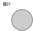
- 21 is a sectional view taken along line AA in FIG. 20
- FIG. 22 is a sectional view taken along line BB in FIG. 20
- FIG. 23 is a sectional view taken along line CC in FIG.
- the tortoiseshell coil 30 has a first slot accommodating portion 121 and a slot 5 different from the slot 5 in which the first slot accommodating portion 121 is disposed, from a radial position where the first slot accommodating portion 121 is disposed.
- the coil end portions 13 are connected to each other.
- a method for forming the slot storage portions 121 and 122 will be described.
- a plurality of slot storage portions 12 are simultaneously set and molded at the same time.
- the slot storage is performed.
- the parts 12 may be shifted from each other and horizontally arranged.
- one of the slot accommodating portions 121 and 122 uses a lead wire that matches the shape of the slot 5 in the inner peripheral portion or the outer peripheral portion in which it is inserted, and the other is inserted in the other.
- the cross section of the conducting wire may be formed so as to match the shape of the slot 5 in the outer peripheral portion or the inner peripheral portion, and both the slot accommodating portions 121 and 122 may be formed by forming the cross section of the conducting wire. You may make it comprise.
- the first slot housing part 121 is inserted into the gap between the teeth 6 of the inner ring core 3 from the radially outer side of the inner ring core 3.
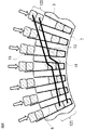
- the second slot storage portion 122 is inserted into the slot 5 different from the slot 5 through which the first slot storage portion 121 is inserted. 25.
- the first slot accommodating portion 121 of the tortoiseshell coil 30 is on the inner peripheral side of the slot 5 and the second slot accommodating portion 122 is on the radial extension of the slot 5 as shown in FIG.
- the same number of slots 5 are arranged in a cylindrical shape.
- the second slot storage portion 122 is collectively inserted from the radial direction.
- the first slot accommodating portions 121 of the turtle shell coil 30 are arranged radially in the same number as the number of the slots 5 so as not to interfere with each other so that the second slot accommodating portions 122 do not interfere with each other.
- the second slot housing part 122 may be rotationally moved around the first slot housing part 121 and inserted into the slot 5.
- an insulating paper 19 is inserted and disposed so as to cover the peripheral portions of the teeth 6 and the connecting portion 7, so that the insulation between the slot accommodating portion 12 and the inner ring core 3 is provided. Secured.
- the conductor coil is the turtle shell coil 30 formed by overlapping and forming the conductive wire in a substantially hexagonal shape
- the shape of the coil is simplified. That is, as can be seen by comparing FIG. 20 with FIGS. 5 and 11, the conductor coil as a manufacturing unit becomes small, and the mold for forming the coil has a small and simple structure.
- stator 1 it becomes possible to manufacture the stator 1 at low cost, and the assemblability is improved. Furthermore, since the length of the slot accommodating part 12 can be changed easily, a design freedom increases.
- the stator coil 10 can be configured by the coil 30. Thereby, since parts are made common, it becomes possible to manufacture the stator 1 at low cost and also improve the assembling performance.
- the tortoiseshell coil 30 has the first slot accommodating portion 121 and the second slot accommodating portion 122 as an aggregate of two slot accommodating portions 12, respectively. It is not limited to this, and the number of each slot storage portion 12 may be different.
- the second slot storage unit 122 is arranged outside the first slot storage unit 121, but the arrangement is not limited to this. For example, both the first and second slot storage units 121 and 122 are provided in the slot 5.
- a structure in which another turtle shell coil 30 is inserted and arranged on the outer peripheral side of the slot 5 may be used.
- the number of slots 5 of the stator 1 is shown as 48, this number is not limited to this. Further, although the number of the slot accommodating portions 12 arranged in the radial direction is four, this number is not limited to this. Furthermore, although the number of tortoise shell coils 30 to be inserted is the same as the number of slots 5, the present invention is not limited to this. For example, a configuration in which n times the number of tortoise shell coils 30 of the number of slots 5 may be inserted.
- the rotary electric machine according to the first to third embodiments described here is used for, for example, a drive motor for an electric power steering of an automobile, but the application is not limited to this.
Landscapes
- Engineering & Computer Science (AREA)
- Power Engineering (AREA)
- Manufacturing & Machinery (AREA)
- Manufacture Of Motors, Generators (AREA)
- Windings For Motors And Generators (AREA)
- Iron Core Of Rotating Electric Machines (AREA)
Abstract
Description
そして、前記幅調整部を設けたスロットへの挿入を可能とするため、固定子コイルを、2本の直線部とそれを繋ぐ連結部とを有する略U字状に形成し、この固定子コイルの直線部の断面を、前記幅調整部に沿った形状、および、径方向両端部を径方向と直交する方向に沿った形状に成形した後、スロットにその軸方向から挿通配置する。これにより、固定子コイルとスロットとの間の隙間を狭め、固定子の占積率を向上させることができる。
固定子は、固定子コアと固定子コイルとを備え、
固定子コアは、径方向に延びると共に周方向に間隔をあけて配置された複数のティースと複数のティースの内周部を連結する連結部とからなる内輪コア、および筒状に形成され複数のティースの外周面に接合可能に構成された外輪コアを備え、
固定子コアの隣接するティースの間に形成されるスロットは、ティースの周方向幅が径方向に沿ってほぼ一定となるよう、その内周部の周方向幅が、その外周部の周方向幅より小さくなるように形成され、
固定子コイルは、導線を成形してなる導体コイルを複数個接続して構成されており、導体コイルは、スロットの内部に配置される複数のスロット収納部と、スロットの外部で複数のスロット収納部を連結する複数のコイルエンド部とを備えたものである。
本発明の実施の形態1に係る回転電機の固定子の構造を、固定子1を示す図1、固定子コア2を示す図2、固定子コア2の要部断面を示す図3、導体コイル11の断面を示す図4、導体コイル11の要部を示す図5、導体コイル11の要部断面を示す図6、および固定子1の要部上面を示す図7を参照して説明する。
なお、図示は省略しているが、回転電機の中央に回転子が位置し、この回転子の外周側に固定子1が配置される。
図3(A)のスロット5では、途中に段差8を設け、スロット5の内周部の周方向幅aを外周部の周方向幅bよりも狭めている。図3(B)のスロット5では、スロット5の途中から、外周側から内周側に向かうにつれて徐々に周方向幅を狭めるテーパ9を設け、スロット5の内周部の周方向幅aを外周部の周方向幅bよりも狭めている。図3(C)のスロット5では、スロット5の側面全域にわたって、テーパ9を設けている。
なお、本実施の形態1ではスロット5およびティース6をそれぞれ48個として示している。
なお、スロット5の内周側に、円形断面形状の第一導体コイルであるスロット収納部12aを配置し、外周側に、平角断面形状の第二導体コイルであるスロット収納部12bを配置してもよい。また、例えば、径の異なる円形断面形状のスロット収納部12a、12bを配置してもよい。
各図に示すように、本実施の形態1では、同一スロット5内に径方向に並ぶスロット収納部12の数を4本、その断面形状を2種類として示している。
先ず、内輪コア3のティース6間の隙間に、スロット収納部12を内輪コア3の径方向外方から挿入する(挿入配置工程)。この挿入方法としては、必要数の導体コイル11を、予め、内輪コア3より若干径が大きい治具上に略円筒状に形成しておき、これを、図8に示すように、径方向内方へ一括挿入する方法がある。この場合、径方向の圧縮による導体コイル11の若干の変形は、固定子コア2の軸方向両端外方へ吸収される。
その後、導体コイル11のコイル端部15同士を、例えば、TIG溶接、抵抗溶接等にて接合する(接合工程)。接合部は、コイル端部15を2本、1箇所に集めて接合して構成する。但し、中性点は、UVWの3点を接続する必要があるため、コイル端部15を3本、1個所に集めて接合する。また、電源、インバータ等他のデバイスと接続するコイル端部15については、他デバイスと接続させるための仲介部品(端子等)を別途接合するか、もしくは、この段階では何もせず、次工程に進む。
また、回転電機を駆動制御するインバータ(図示せず)を2つ用いて、独立した2つの駆動回路を持たせることができ、冗長性を得ることができる。
従って、第一導体コイル、第二導体コイルとも、そのコイルエンド部13を無理なく構成することが出来、結果として、固定子コイル10の抵抗が低減し、回転電機の効率、出力が向上する。
また、固定子コア2の剛性が高くなることで、回転電機の振動・騒音を抑制することができ、回転電機の性能、品質、信頼性が向上する。
また、駆動回路を並列化することで、それぞれの回路に流れる電流を低減させることができる。これにより、特に小容量機であって、巻線作業等機械的ストレスに耐えるために導体に下限の同一サイズのものが採用される場合等では、回転電機の損失が低減し、回転電機の性能、信頼性が向上する。
本発明の実施の形態2に係る回転電機の固定子の構造を、導体コイル11の要部断面を示す図10、および導体コイル11の要部を示す図11を参照して説明する。但し、先の実施の形態1と実質的に同じ構成部品に対しては同じ符号を付し、個々の説明を省略する。
実施の形態2は、その導体コイル11のスロット収納部12の断面形状を、元の導線の断面形状と異なる形に成形した点が実施の形態1と異なり、以下この部分を中心に説明する。
図11に、本実施の形態2の導体コイル11の外観を示す。スロット収納部12は、その断面形状を略台形形状になるように成形している。図12は図11におけるA-A線断面図、図13は図11におけるB-B線断面図、図14は図11におけるC-C線断面図である。
なお、図18では、図10のスロット5の最内周に挿通配置されるスロット収納部12の断面形状について示したが、他の断面についても、同様の成形を行っている。
また、スロット収納部12を成形する際には、複数本を同時に一括で成形するため、断面形状を精度よく成形することが可能となり、よりスロット形状に近づけることができる。これにより、固定子1の占積率を上げることができ、固定子コイル10の抵抗が低減し、回転電機の効率、出力が向上する。
本発明の実施の形態3に係る回転電機の固定子の構造を、固定子1を示す図19および導体コイルである亀甲コイル30を示す図20を参照して説明する。但し、先の実施の形態1、2と実質的に同じ構成部品に対しては同じ符号を付し、適宜個々の説明は省略する。
実施の形態3は、その導体コイルを、導線を略六角形状に重ね巻き成形してなる亀甲コイル30とした点が実施の形態1、2と異なり、以下この部分を中心に説明する。
次に、図20を用いて、亀甲コイル30の構造を説明する。亀甲コイル30は、導体部17と、導体部17の表面を被覆する絶縁皮膜18とからなる1本の導線を略六角形状に重ね巻き成形して構成している。尚図21は図20におけるA-A線断面図、図22は図20におけるB-B線断面図、図23は図20におけるC-C線断面図である。
内輪コア3のティース6間の隙間に、第一スロット収納部121を内輪コア3の径方向外方から挿入する。その後、第二スロット収納部122を、第一スロット収納部121を挿通配置したスロット5と別のスロット5に挿通配置する。
挿入方法であるが、図25に示すように、亀甲コイル30の第一スロット収納部121をスロット5の内周側に、第二スロット収納部122をスロット5の径方向延長上にくるように、スロット5の数と同数円筒状に配置する。その後、第二スロット収納部122を径方向から一括挿入する。
なお、スロット収納部12を挿入する前に、ティース6および連結部7の周縁部を覆うように絶縁紙19を挿入配置しており、スロット収納部12と内輪コア3との間の絶縁性を確保している。
即ち、図20を先の図5、図11と比べてみると判るように、製作単位となる導体コイルが小型となり、コイルを成形するための型も小型で簡単な構造のものとなる。
更に、スロット収納部12の長さを容易に変更することができるため、設計自由度が増す。
また、第二スロット収納部122を第一スロット収納部121の外側に配置したが、配置はこれに限定されるものではなく、例えば、第一、第二スロット収納部121、122とも、スロット5の内周側に配置し、スロット5の外周側には別の亀甲コイル30を挿通配置する構造であってもよい。
Claims (13)
- 回転子とこの回転子の外周側に配置された固定子とを備えた回転電機であって、
前記固定子は、固定子コアと固定子コイルとを備え、
前記固定子コアは、径方向に延びると共に周方向に間隔をあけて配置された複数のティースと前記複数のティースの内周部を連結する連結部とからなる内輪コア、および筒状に形成され前記複数のティースの外周面に接合可能に構成された外輪コアを備え、
前記固定子コアの隣接する前記ティースの間に形成されるスロットは、前記ティースの周方向幅が径方向に沿ってほぼ一定となるよう、その内周部の周方向幅が、その外周部の周方向幅より小さくなるように形成され、
前記固定子コイルは、導線を成形してなる導体コイルを複数個接続して構成されており、前記導体コイルは、前記スロットの内部に配置される複数のスロット収納部と、前記スロットの外部で前記複数のスロット収納部を連結する複数のコイルエンド部とを備えた回転電機。 - 前記スロットは、その径方向の途中に段差を設けることにより、その内周部の周方向幅が、その外周部の周方向幅より小さく形成されている請求項1記載の回転電機。
- 前記スロットは、その径方向にテーパを設けることにより、その内周部の周方向幅が、その外周部の周方向幅より小さく形成されている請求項1記載の回転電機。
- 前記導体コイルは、第一導体コイルと前記スロット内の径方向位置が前記第一導体コイルより外周側に配置される第二導体コイルをと有し、同一の前記スロットの内部に配置される複数の前記スロット収納部の占積率が上がるよう、前記第一導体コイルと前記第二導体コイルとは、それぞれ断面形状が互いに異なる導線を使用した請求項1から請求項3のいずれか1項に記載の回転電機。
- 前記スロット収納部は、同一の前記スロットの内部に配置される複数の前記スロット収納部の占積率が上がるよう、前記導線の断面形状と異なる断面形状に成形されている請求項1から請求項3のいずれか1項に記載の回転電機。
- 前記成形されたスロット収納部が前記コイルエンド部に滑らかに連なるよう、前記スロット収納部と前記コイルエンド部との境界に円弧状もしくはテーパ状の中継部を形成した請求項5記載の回転電機。
- 前記導体コイルは、前記導線を略六角形状に重ね巻き成形され、前記スロット収納部として、それぞれ複数本の前記導線で構成された第一スロット収納部およびこの第一スロット収納部が配置されるスロットとは異なるスロットに配置される第二スロット収納部を備えた亀甲コイルである請求項1記載の回転電機。
- 前記スロット内において、前記第二スロット収納部は、前記第一スロット収納部が配置される径方向位置より外周側に配置される請求項7記載の回転電機。
- 前記導体コイルのコイルエンド部は、このコイルエンド部の両端に連結される前記スロット収納部の径方向位置の差を吸収するためのレーンチェンジ部を備えた請求項1記載の回転電機。
- 前記固定子は、毎極毎相の前記スロットの数が2以上の分布巻方式とし、前記複数個の導体コイルで多相の固定子コイル群を構成し、前記各固定子コイル群は、互いに異なる駆動回路に接続するようにした請求項1記載の回転電機。
- 回転子とこの回転子の外周側に配置された固定子とを備えた回転電機の製造方法であって、
前記固定子は、固定子コアと固定子コイルとを備え、
前記固定子コアは、径方向に延びると共に周方向に間隔をあけて配置された複数のティースと前記複数のティースの内周部を連結する連結部とからなる内輪コア、および筒状に形成され前記複数のティースの外周面に接合可能に構成された外輪コアを備え、
前記固定子コアの隣接する前記ティースの間に形成されるスロットは、前記ティースの周方向幅が径方向に沿ってほぼ一定となるよう、その内周部の周方向幅が、その外周部の周方向幅より小さくなるように形成され、
前記固定子コイルは、導線を成形してなる導体コイルを複数個接続して構成されており、前記導体コイルは、前記スロットの内部に配置される複数のスロット収納部と、前記スロットの外部で前記複数のスロット収納部を連結する複数のコイルエンド部とを備えており、
前記スロット収納部を前記内輪コアの径方向外方から前記ティース間に挿入することにより前記複数個の導体コイルを前記内輪コアのスロット内に配置する挿入配置工程、前記導体コイルが挿入配置された内輪コアの外周面に前記外輪コアを接合組み付けるコア結合工程、および前記導体コイルの端部を接合して前記固定子コイルを形成する接合工程を備えた回転電機の製造方法。 - 回転子とこの回転子の外周側に配置された固定子とを備えた回転電機の製造方法であって、
前記固定子は、固定子コアと固定子コイルとを備え、
前記固定子コアは、径方向に延びると共に周方向に間隔をあけて配置された複数のティースと前記複数のティースの内周部を連結する連結部とからなる内輪コア、および筒状に形成され前記複数のティースの外周面に接合可能に構成された外輪コアを備え、
前記固定子コアの隣接する前記ティースの間に形成されるスロットは、前記ティースの周方向幅が径方向に沿ってほぼ一定となるよう、その内周部の周方向幅が、その外周部の周方向幅より小さくなるように形成され、
前記固定子コイルは、導線を成形してなる導体コイルを複数個接続して構成されており、前記導体コイルは、前記スロットの内部に配置される複数のスロット収納部と、前記スロットの外部で前記複数のスロット収納部を連結する複数のコイルエンド部とを備えており、
前記スロット収納部は、同一の前記スロットの内部に配置される複数の前記スロット収納部の占積率が上がるよう、前記導線の断面形状と異なる断面形状に成形されており、
同一の前記スロットに配置される複数本の前記導線を、前記スロットの形状に合わせた型内にセットし、一括加圧することにより前記スロット収納部を成形するようにした回転電機の製造方法。 - 前記導線を、表面にエナメルを焼き付けてなる絶縁皮膜を形成したものとし、前記一括加圧の処理により、前記絶縁皮膜の断面角部の厚さが他部より厚くなるようにした請求項12記載の回転電機の製造方法。
Priority Applications (4)
| Application Number | Priority Date | Filing Date | Title |
|---|---|---|---|
| JP2015519696A JP6072238B2 (ja) | 2013-05-28 | 2014-03-04 | 回転電機の製造方法 |
| EP14804684.0A EP3007319B1 (en) | 2013-05-28 | 2014-03-04 | Rotary electric machine, and manufacturing method therefor |
| US14/779,445 US9923438B2 (en) | 2013-05-28 | 2014-03-04 | Method for manufacturing a rotary electric machine |
| CN201480026979.8A CN105210267B (zh) | 2013-05-28 | 2014-03-04 | 旋转电机及其制造方法 |
Applications Claiming Priority (2)
| Application Number | Priority Date | Filing Date | Title |
|---|---|---|---|
| JP2013-111706 | 2013-05-28 | ||
| JP2013111706 | 2013-05-28 |
Publications (1)
| Publication Number | Publication Date |
|---|---|
| WO2014192350A1 true WO2014192350A1 (ja) | 2014-12-04 |
Family
ID=51988394
Family Applications (1)
| Application Number | Title | Priority Date | Filing Date |
|---|---|---|---|
| PCT/JP2014/055375 Ceased WO2014192350A1 (ja) | 2013-05-28 | 2014-03-04 | 回転電機およびその製造方法 |
Country Status (5)
| Country | Link |
|---|---|
| US (1) | US9923438B2 (ja) |
| EP (1) | EP3007319B1 (ja) |
| JP (1) | JP6072238B2 (ja) |
| CN (1) | CN105210267B (ja) |
| WO (1) | WO2014192350A1 (ja) |
Cited By (6)
| Publication number | Priority date | Publication date | Assignee | Title |
|---|---|---|---|---|
| JPWO2014174658A1 (ja) * | 2013-04-26 | 2017-02-23 | 三菱電機株式会社 | 電機子コイル及びその製造方法 |
| KR20190037759A (ko) * | 2017-09-29 | 2019-04-08 | 한국생산기술연구원 | 분포권 평각형 전기자 권선 및 이를 포함하는 모터, 그리고 이들의 제조방법 |
| WO2020022281A1 (ja) * | 2018-07-25 | 2020-01-30 | 株式会社デンソー | 電機子巻線の製造方法 |
| JP2020025440A (ja) * | 2018-07-25 | 2020-02-13 | 株式会社デンソー | 電機子巻線の製造方法 |
| WO2021235344A1 (ja) * | 2020-05-18 | 2021-11-25 | 株式会社デンソー | 回転電機、及び回転電機の製造方法 |
| KR20220160485A (ko) * | 2021-05-27 | 2022-12-06 | 독터. 인제니어. 하.체. 에프. 포르쉐 악티엔게젤샤프트 | 전기 구동 기계의 고정자, 및 이를 제조하기 위한 방법 |
Families Citing this family (32)
| Publication number | Priority date | Publication date | Assignee | Title |
|---|---|---|---|---|
| FR3019947B1 (fr) * | 2014-04-10 | 2017-12-08 | Moteurs Leroy-Somer | Stator de machine electrique tournante. |
| FR3019948B1 (fr) | 2014-04-10 | 2017-12-22 | Moteurs Leroy-Somer | Rotor de machine electrique tournante. |
| DE102016211833A1 (de) * | 2016-06-30 | 2018-01-04 | Robert Bosch Gmbh | Wicklungsträger |
| CN107070017A (zh) * | 2017-05-24 | 2017-08-18 | 乐视汽车(北京)有限公司 | 一种电机的定子及其制造方法 |
| US20180367005A1 (en) * | 2017-06-14 | 2018-12-20 | GM Global Technology Operations LLC | Stator assembly with uneven conductors |
| JP7131373B2 (ja) * | 2018-12-26 | 2022-09-06 | トヨタ自動車株式会社 | コイル線の溶接方法 |
| KR102700954B1 (ko) * | 2019-01-04 | 2024-08-29 | 현대모비스 주식회사 | 헤어핀 권선모터의 고정자 어셈블리 |
| GB201906455D0 (en) * | 2019-05-08 | 2019-06-19 | Rolls Royce Plc | Electric machines |
| US20220399764A1 (en) * | 2019-11-12 | 2022-12-15 | Mavel edt S.p.A. | Synchronous electric machine with reluctance assisted by permanent magnets and process for making such electric machine |
| WO2021095064A1 (en) * | 2019-11-12 | 2021-05-20 | Mavel edt S.p.A. | Stator with closed slots with continuous winding for an electric machine and process for making such stator |
| WO2021095065A1 (en) * | 2019-11-12 | 2021-05-20 | Mavel edt S.p.A. | Process for making a continuous winding for a stator of an electric machine and winding made with such process |
| CN110880844B (zh) * | 2019-11-21 | 2024-11-29 | 上海华太智科信息技术有限公司 | 定子线圈收紧装置以及对线圈进行收紧的方法 |
| KR102414209B1 (ko) * | 2019-12-04 | 2022-06-28 | 현대모비스 주식회사 | 헤어핀 권선모터의 고정자 어셈블리 및 이의 제조방법 |
| CN112928835B (zh) * | 2019-12-05 | 2023-01-06 | 比亚迪股份有限公司 | 成型绕组以及具有其的电机 |
| KR102731346B1 (ko) * | 2019-12-16 | 2024-11-15 | 엘지마그나 이파워트레인 주식회사 | 차량용 구동 모터의 고정자 및 이를 포함하는 차량용 구동 모터 |
| CN111049336B (zh) * | 2020-01-14 | 2024-08-02 | 上海华太智科信息技术有限公司 | 马达的定子线圈收紧装置以及线圈收紧方法 |
| FR3112905B1 (fr) * | 2020-07-23 | 2023-06-09 | Nidec Psa Emotors | Stator de machine électrique tournante |
| KR20220028784A (ko) * | 2020-08-31 | 2022-03-08 | 현대모비스 주식회사 | 코일 어셈블리 및 이를 구비한 모터 |
| JP7428114B2 (ja) * | 2020-11-09 | 2024-02-06 | トヨタ自動車株式会社 | ステータ |
| DE102020215913A1 (de) | 2020-12-15 | 2022-06-15 | Valeo Siemens Eautomotive Germany Gmbh | Statorkern, Anordnung mit einem Statorkern und mit Nutauskleidungen, Stator, elektrischer Maschine und Fahrzeug |
| FR3118340A1 (fr) * | 2020-12-17 | 2022-06-24 | Nidec Psa Emotors | Stator avec une couronne ayant des encoches ouvertes radialement vers l’extérieur et recevant des bobines et une culasse rapportée. |
| US20240313590A1 (en) * | 2020-12-31 | 2024-09-19 | Mavel edt S.p.A. | Stator with closed slots with continuous winding for an electric machine and process for making such stator |
| DE102021203787A1 (de) * | 2021-04-16 | 2022-11-03 | Valeo Eautomotive Germany Gmbh | Stator für eine elektrische Maschine, Verfahren zur Herstellung eines Stators für eine elektrische Maschine, elektrische Maschine und Fahrzeug |
| DE102021125488A1 (de) | 2021-10-01 | 2023-04-06 | Schaeffler Technologies AG & Co. KG | Stator einer elektrischen Rotationsmaschine sowie elektrische Rotationsmaschine |
| CN114614608B (zh) * | 2022-01-21 | 2024-04-19 | 安徽沃弗永磁科技有限公司 | 一种具有双层定子绕组的永磁电机 |
| DE102022101619A1 (de) | 2022-01-25 | 2023-07-27 | Schaeffler Technologies AG & Co. KG | Verfahren zur Umformung einer Wellenwicklung und eine nach dem Verfahren umgeformte Wellenwicklung |
| GB2615358B (en) * | 2022-02-07 | 2024-06-26 | Hispeed Ltd | Stator with asymmetric material bridges for an electric machine |
| CN115037077B (zh) * | 2022-06-27 | 2025-08-26 | 北京交通大学 | 设有带保护层的阶梯绕组和阶梯槽的电机定子及永磁电机 |
| WO2024054859A1 (en) | 2022-09-06 | 2024-03-14 | Harbinger Motors Inc. | Fractional-slot-winding motors and electrical vehicles comprising thereof |
| DE102022133230A1 (de) | 2022-12-14 | 2024-06-20 | Schaeffler Technologies AG & Co. KG | Verfahren zur Umformung und Einbringung einer Wicklung in einen Rotor- oder Statorkörper |
| CN116054459A (zh) * | 2023-02-20 | 2023-05-02 | 浙江博来工具有限公司 | 无刷外绕线防吸附电机 |
| FR3165747A1 (fr) * | 2024-08-20 | 2026-02-27 | Liebherr-Aerospace Toulouse Sas | Procédé de bobinage distribué avec insertion simultanée et directe des bobines sans outillage relais |
Citations (9)
| Publication number | Priority date | Publication date | Assignee | Title |
|---|---|---|---|---|
| JPH02285953A (ja) * | 1989-04-26 | 1990-11-26 | Nippondenso Co Ltd | 電機子コイルの装填方法 |
| JP2000224788A (ja) * | 1998-11-25 | 2000-08-11 | Toyota Motor Corp | モ―タ及びモ―タ用コイルユニットの製造方法 |
| JP2007288848A (ja) * | 2006-04-13 | 2007-11-01 | Hitachi Ltd | 回転電機のステータ及びその製造方法及び交流発電機 |
| JP2007325447A (ja) * | 2006-06-02 | 2007-12-13 | Toshiba Mitsubishi-Electric Industrial System Corp | 多相電動機 |
| WO2008044703A1 (en) * | 2006-10-12 | 2008-04-17 | Mitsubishi Electric Corporation | Stator of rotating electric machine |
| JP2008148480A (ja) * | 2006-12-12 | 2008-06-26 | Nippon Densan Corp | モータ |
| JP2010263771A (ja) * | 2009-04-06 | 2010-11-18 | Denso Corp | ステータコイルのコイルエンド成形方法および成形装置 |
| JP2012222983A (ja) * | 2011-04-11 | 2012-11-12 | Hitachi Automotive Systems Ltd | 固定子および回転電機 |
| JP2013005683A (ja) | 2011-06-21 | 2013-01-07 | Asmo Co Ltd | ステータ及びモータ |
Family Cites Families (21)
| Publication number | Priority date | Publication date | Assignee | Title |
|---|---|---|---|---|
| JPH0732551B2 (ja) * | 1985-04-15 | 1995-04-10 | 株式会社日立製作所 | 回転電機子コイルの成形方法 |
| JPH06101904B2 (ja) * | 1987-03-20 | 1994-12-12 | 株式会社日立製作所 | 多重巻亀甲形固定子コイルの結線方法 |
| JPH02261025A (ja) * | 1989-03-29 | 1990-10-23 | Mitsubishi Electric Corp | 電動機の固定子 |
| JP3102665B2 (ja) * | 1992-02-17 | 2000-10-23 | 三菱電機株式会社 | 電動機 |
| JP2836463B2 (ja) * | 1993-10-26 | 1998-12-14 | 住友電装株式会社 | 圧接ジョイントコネクタ |
| JP3745884B2 (ja) * | 1997-08-20 | 2006-02-15 | ミネベア株式会社 | モータ構造及びその製造方法 |
| US6046518A (en) * | 1999-01-21 | 2000-04-04 | Williams; Malcolm R. | Axial gap electrical machine |
| JP4366823B2 (ja) | 1999-11-18 | 2009-11-18 | 日本精工株式会社 | パワーステアリング用ブラシレスモータの制御装置 |
| JP2001320845A (ja) | 2000-05-10 | 2001-11-16 | Mitsubishi Electric Corp | 回転電機の固定子 |
| DE60208387T2 (de) * | 2002-10-08 | 2006-08-24 | Mitsubishi Denki K.K. | Stator für einen Fahrzeuggenerator |
| JP2005124361A (ja) * | 2003-10-20 | 2005-05-12 | Toyota Industries Corp | 回転電機およびその製造方法 |
| JP4419510B2 (ja) * | 2003-10-20 | 2010-02-24 | 株式会社豊田自動織機 | モータ、電機子、または発電機 |
| US7508157B1 (en) * | 2005-01-18 | 2009-03-24 | Gabrys Christopher W | Line synchronous air core motor |
| JP4706339B2 (ja) * | 2005-06-03 | 2011-06-22 | 株式会社富士通ゼネラル | アキシャルエアギャップ型電動機 |
| US7830062B2 (en) | 2006-12-12 | 2010-11-09 | Nidec Corporation | Motor having round and angular coils |
| JP5011152B2 (ja) | 2008-02-14 | 2012-08-29 | 株式会社日立製作所 | 回転電機、並びに回転電機の製造方法 |
| JP4600508B2 (ja) * | 2008-04-21 | 2010-12-15 | 株式会社デンソー | インナーロータ型回転電機のステータ製造方法 |
| US8058765B2 (en) * | 2009-06-19 | 2011-11-15 | GM Global Technology Operations LLC | Methods and apparatus for a bar-wound stator with rotated conductors |
| JPWO2011155327A1 (ja) * | 2010-06-10 | 2013-08-01 | 本田技研工業株式会社 | 電動機の突極集中巻きステータ及びその製造方法 |
| GB2491573A (en) * | 2011-05-31 | 2012-12-12 | Cummins Generator Technologies | Two part stator for an electrical machine |
| JP5454804B2 (ja) * | 2011-08-12 | 2014-03-26 | 古河電気工業株式会社 | 絶縁ワイヤ |
-
2014
- 2014-03-04 JP JP2015519696A patent/JP6072238B2/ja active Active
- 2014-03-04 WO PCT/JP2014/055375 patent/WO2014192350A1/ja not_active Ceased
- 2014-03-04 US US14/779,445 patent/US9923438B2/en active Active
- 2014-03-04 EP EP14804684.0A patent/EP3007319B1/en active Active
- 2014-03-04 CN CN201480026979.8A patent/CN105210267B/zh active Active
Patent Citations (9)
| Publication number | Priority date | Publication date | Assignee | Title |
|---|---|---|---|---|
| JPH02285953A (ja) * | 1989-04-26 | 1990-11-26 | Nippondenso Co Ltd | 電機子コイルの装填方法 |
| JP2000224788A (ja) * | 1998-11-25 | 2000-08-11 | Toyota Motor Corp | モ―タ及びモ―タ用コイルユニットの製造方法 |
| JP2007288848A (ja) * | 2006-04-13 | 2007-11-01 | Hitachi Ltd | 回転電機のステータ及びその製造方法及び交流発電機 |
| JP2007325447A (ja) * | 2006-06-02 | 2007-12-13 | Toshiba Mitsubishi-Electric Industrial System Corp | 多相電動機 |
| WO2008044703A1 (en) * | 2006-10-12 | 2008-04-17 | Mitsubishi Electric Corporation | Stator of rotating electric machine |
| JP2008148480A (ja) * | 2006-12-12 | 2008-06-26 | Nippon Densan Corp | モータ |
| JP2010263771A (ja) * | 2009-04-06 | 2010-11-18 | Denso Corp | ステータコイルのコイルエンド成形方法および成形装置 |
| JP2012222983A (ja) * | 2011-04-11 | 2012-11-12 | Hitachi Automotive Systems Ltd | 固定子および回転電機 |
| JP2013005683A (ja) | 2011-06-21 | 2013-01-07 | Asmo Co Ltd | ステータ及びモータ |
Non-Patent Citations (1)
| Title |
|---|
| See also references of EP3007319A4 * |
Cited By (11)
| Publication number | Priority date | Publication date | Assignee | Title |
|---|---|---|---|---|
| JPWO2014174658A1 (ja) * | 2013-04-26 | 2017-02-23 | 三菱電機株式会社 | 電機子コイル及びその製造方法 |
| KR20190037759A (ko) * | 2017-09-29 | 2019-04-08 | 한국생산기술연구원 | 분포권 평각형 전기자 권선 및 이를 포함하는 모터, 그리고 이들의 제조방법 |
| KR102128046B1 (ko) * | 2017-09-29 | 2020-06-29 | 한국생산기술연구원 | 분포권 평각형 전기자 권선 및 이를 포함하는 모터, 그리고 이들의 제조방법 |
| WO2020022281A1 (ja) * | 2018-07-25 | 2020-01-30 | 株式会社デンソー | 電機子巻線の製造方法 |
| JP2020025440A (ja) * | 2018-07-25 | 2020-02-13 | 株式会社デンソー | 電機子巻線の製造方法 |
| JP7251340B2 (ja) | 2018-07-25 | 2023-04-04 | 株式会社デンソー | 電機子巻線の製造方法 |
| WO2021235344A1 (ja) * | 2020-05-18 | 2021-11-25 | 株式会社デンソー | 回転電機、及び回転電機の製造方法 |
| JP2021182809A (ja) * | 2020-05-18 | 2021-11-25 | 株式会社デンソー | 回転電機、及び回転電機の製造方法 |
| JP7532892B2 (ja) | 2020-05-18 | 2024-08-14 | 株式会社デンソー | 回転電機、及び回転電機の製造方法 |
| KR20220160485A (ko) * | 2021-05-27 | 2022-12-06 | 독터. 인제니어. 하.체. 에프. 포르쉐 악티엔게젤샤프트 | 전기 구동 기계의 고정자, 및 이를 제조하기 위한 방법 |
| KR102736649B1 (ko) | 2021-05-27 | 2024-12-03 | 독터. 인제니어. 하.체. 에프. 포르쉐 악티엔게젤샤프트 | 전기 구동 기계의 고정자, 및 이를 제조하기 위한 방법 |
Also Published As
| Publication number | Publication date |
|---|---|
| CN105210267B (zh) | 2018-06-26 |
| EP3007319A4 (en) | 2017-03-22 |
| JPWO2014192350A1 (ja) | 2017-02-23 |
| EP3007319B1 (en) | 2020-10-28 |
| EP3007319A1 (en) | 2016-04-13 |
| JP6072238B2 (ja) | 2017-02-01 |
| US9923438B2 (en) | 2018-03-20 |
| CN105210267A (zh) | 2015-12-30 |
| US20160056696A1 (en) | 2016-02-25 |
Similar Documents
| Publication | Publication Date | Title |
|---|---|---|
| JP6072238B2 (ja) | 回転電機の製造方法 | |
| JP5070248B2 (ja) | 回転電機とその製造方法 | |
| CN103503278B (zh) | 定子及定子制造方法 | |
| JP6033582B2 (ja) | ステータおよびステータの製造方法 | |
| JP5918353B2 (ja) | 回転電機のステータ構造 | |
| JP4270307B2 (ja) | 渡り線モジュール | |
| CN101728888B (zh) | 用于电机线圈的配线部件 | |
| KR20120041127A (ko) | 고정자, 브러시리스 모터 및 이의 제조방법 | |
| US20090134737A1 (en) | Stator of electric rotating machine and electric rotating machine | |
| JP5626758B2 (ja) | ステータ | |
| JP2014007938A (ja) | 回転電機及び回転電機の製造方法 | |
| CN108370184B (zh) | 旋转电机 | |
| JP2013223322A (ja) | 回転電機およびその製造方法 | |
| US8659201B2 (en) | Stator for electric rotating machine | |
| JP6305203B2 (ja) | 回転電機の固定子及び固定子の製造方法 | |
| JP2009106008A (ja) | 回転電機の固定子 | |
| JP2019037103A (ja) | ステータ及びモータ | |
| US20150372551A1 (en) | Structure of stator | |
| JP6968215B2 (ja) | 回転電機 | |
| WO2025126943A1 (ja) | ステータ及びモータ |
Legal Events
| Date | Code | Title | Description |
|---|---|---|---|
| 121 | Ep: the epo has been informed by wipo that ep was designated in this application |
Ref document number: 14804684 Country of ref document: EP Kind code of ref document: A1 |
|
| ENP | Entry into the national phase |
Ref document number: 2015519696 Country of ref document: JP Kind code of ref document: A |
|
| WWE | Wipo information: entry into national phase |
Ref document number: 14779445 Country of ref document: US |
|
| WWE | Wipo information: entry into national phase |
Ref document number: 2014804684 Country of ref document: EP |
|
| NENP | Non-entry into the national phase |
Ref country code: DE |