WO2014192783A1 - バッテリ式穿孔機 - Google Patents
バッテリ式穿孔機 Download PDFInfo
- Publication number
- WO2014192783A1 WO2014192783A1 PCT/JP2014/064059 JP2014064059W WO2014192783A1 WO 2014192783 A1 WO2014192783 A1 WO 2014192783A1 JP 2014064059 W JP2014064059 W JP 2014064059W WO 2014192783 A1 WO2014192783 A1 WO 2014192783A1
- Authority
- WO
- WIPO (PCT)
- Prior art keywords
- battery
- battery cover
- cover
- punching machine
- drilling
- Prior art date
- Legal status (The legal status is an assumption and is not a legal conclusion. Google has not performed a legal analysis and makes no representation as to the accuracy of the status listed.)
- Ceased
Links
Images


Classifications
-
- B—PERFORMING OPERATIONS; TRANSPORTING
- B23—MACHINE TOOLS; METAL-WORKING NOT OTHERWISE PROVIDED FOR
- B23B—TURNING; BORING
- B23B45/00—Hand-held or like portable drilling machines, e.g. drill guns; Equipment therefor
- B23B45/02—Hand-held or like portable drilling machines, e.g. drill guns; Equipment therefor driven by electric power
-
- B—PERFORMING OPERATIONS; TRANSPORTING
- B23—MACHINE TOOLS; METAL-WORKING NOT OTHERWISE PROVIDED FOR
- B23B—TURNING; BORING
- B23B45/00—Hand-held or like portable drilling machines, e.g. drill guns; Equipment therefor
- B23B45/001—Housing of the drill, e.g. handgrip
-
- B—PERFORMING OPERATIONS; TRANSPORTING
- B25—HAND TOOLS; PORTABLE POWER-DRIVEN TOOLS; MANIPULATORS
- B25H—WORKSHOP EQUIPMENT, e.g. FOR MARKING-OUT WORK; STORAGE MEANS FOR WORKSHOPS
- B25H1/00—Work benches; Portable stands or supports for positioning portable tools or work to be operated on thereby
- B25H1/0021—Stands, supports or guiding devices for positioning portable tools or for securing them to the work
- B25H1/0057—Devices for securing hand tools to the work
- B25H1/0064—Stands attached to the workpiece
- B25H1/0071—Stands attached to the workpiece by magnetic means
-
- B—PERFORMING OPERATIONS; TRANSPORTING
- B23—MACHINE TOOLS; METAL-WORKING NOT OTHERWISE PROVIDED FOR
- B23B—TURNING; BORING
- B23B2260/00—Details of constructional elements
- B23B2260/024—Batteries
Definitions
- the present invention relates to a portable drilling machine driven by a battery.
- a portable drilling machine has a main body frame and a motor that rotationally drives a drilling tool such as a drill or an annular cutter, as described in Patent Document 1, for example, and is mounted so as to move up and down with respect to the main body frame. And a fixing portion provided at a lower portion of the main body frame for fixing and holding the punching machine detachably with respect to the workpiece.
- the main body frame has an internal space in which a drive control unit for controlling a motor and the like of the perforation drive unit, electrical wiring, and the like are arranged.
- Such a portable drilling machine is often used in the presence of dust and chips, and in some cases it may be used outdoors when it rains. Is arranged in the internal space of the main body frame in a state of being blocked from the outside.
- Patent Document 2 in order to improve the portability of this type of drilling machine, a machine using a battery for driving a drilling tool has been used.
- a battery-type punch when the battery is used for a certain period of time, the voltage of the battery drops, so it must be replaced with another charged battery.
- frequent battery replacement is required. Therefore, it is desirable that the battery can be attached and detached relatively easily.
- the connection terminals of the battery exposed to the outside are not sufficiently protected from dust and rain, and the battery may be short-circuited by the dust and rain.
- an object of the present invention is to provide a perforator using a battery and protecting the connection terminal of the battery from dust and rain.
- a drilling drive unit having a motor for rotationally driving the drilling tool;
- a drilling machine main body having a battery mounting part to which a battery for supplying power to the motor is mounted, and supporting the drilling driving part so as to move up and down so that the drilling tool is moved closer to or away from the workpiece.
- a battery cover attached to the punching machine main body the battery cover being movable between a retracted position and an advanced position with respect to the battery attached to the battery mounting part, wherein the punching machine main body is in the advanced position
- a battery cover that covers at least a part of a gap formed between the battery and the battery.
- the battery cover covers the gap formed between the perforating machine body and the battery, there is a risk of dust and water entering through the gap and shorting between the battery terminals. It becomes possible to reduce.
- “upper and lower” is used for easy understanding of the positional relative relationship of the constituent elements of the drilling machine according to the present invention. It does not mean up and down in space.
- “movable between the backward position and the forward position with respect to the battery” means that it can move between a position away from the battery and a position approaching the battery. It is not limited to movement in the front-rear direction. Further, the movement path between the reverse position and the forward position is not limited to a straight one, and any path may be used.
- the battery cover when the battery cover is in the forward position, at least a part of the battery cover is a movement path of the battery when the battery attached to the battery attachment portion is removed from the battery attachment portion.
- the battery can be prevented from being removed from the battery mounting portion when the battery cover is in the forward position.
- the punching machine main body is structured to be removable from the battery mounting part by moving the battery upward from the battery mounting part, and the battery cover is in the forward position.
- the gap formed between the punching machine main body and the battery can be covered from above.
- the battery mounting portion has a battery guide extending in the vertical direction for guiding the battery in the vertical direction, and the battery mounting portion is moved down along the battery guide. It can be made to be removed from the battery attachment portion by being raised.
- the gap between the drilling machine main body and the battery extends in the vertical direction, and dust and water enter the gap. Is particularly likely to occur. Even in such a situation, since the battery cover covers the gap from above, it is possible to effectively prevent dust and the like from entering the gap.
- the battery cover can be slidably attached to the punching machine main body between the retracted position and the advanced position.
- the battery cover has a locking portion, A first receiving portion that engages with the locking portion when the battery cover is in the retracted position and inhibits movement of the battery cover in a sliding direction; A second receiving part that engages with the locking part when the battery cover is in the forward movement position and suppresses movement of the battery cover in the sliding direction can be provided.
- the battery cover may have an elastically deformable arm portion extending in the sliding direction, and the locking portion may be provided at the tip of the arm portion.
- the battery cover can be locked in the retracted position and the advanced position by engaging the first and second receiving parts of the punching machine main body with the engaging part of the battery cover. It becomes possible to prevent moving to.
- a battery cover position detection unit that is arranged in the punching machine main body and detects that the battery cover has moved between the retracted position and the advanced position.
- the battery cover position detection means has a limit switch, The battery cover can be turned ON / OFF of the limit switch when moved between the retracted position and the advanced position.
- the limit switch can detect that the battery cover has moved from the forward position to the reverse position, when the battery cover is not in the forward position, the battery is not attached to the normal position or the battery is about to be removed. In such a case, it is possible to take safety measures such as warning the operator or preventing the motor from being driven.
- a spring disposed between the punching machine main body and the battery cover is further provided, and the spring biases the battery cover in a direction from the retracted position toward the advanced position. it can.
- FIG. 2 is a rear perspective view of the punching machine shown in FIG. 1 with a battery removed. It is a perspective view which shows the front surface of a battery.
- FIG. 2 is an upper perspective view of the punching machine shown in FIG. 1 with the battery cover in a retracted position.
- FIG. 2 is an upper perspective view of a state in which a battery cover of the drilling machine shown in FIG. 1 is in an advanced position.
- FIG. 9B is a side view of the battery cover shown in FIG. 9A. It is an upper surface partial sectional view of a perforator with a battery cover in a retreat position. It is an upper surface partial sectional view of a drilling machine in the state where a battery cover exists in an advance position. It is a bottom view of the battery cover which concerns on another embodiment. It is a rear perspective view of the battery cover which concerns on another embodiment.
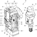
- FIG. 14 is a partial top cross-sectional view of a drilling machine including the battery cover of FIG. 13. It is a perspective view of the state which isolate
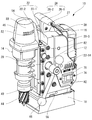
- the drilling machine 10 includes a drilling drive unit 14 having a motor 48 for rotationally driving a drilling tool (annular cutter in the illustrated example) 44, A drilling machine having a battery mounting portion 28 to which a battery 16 for supplying electric power to a motor 48 is mounted, and supporting the drilling drive portion 14 so as to move up and down so that the drilling tool 44 is moved closer to or away from the workpiece.
- a battery-type portable drilling machine 10 including a main body 12. The punching machine 10 is attached to the lower end of the drilling driving unit 14 in a state where the punching machine 10 is fixed to a predetermined drilling work position of the workpiece by an electromagnetic fixing unit 18 attached to the bottom position of the punching machine main body 12.
- the drilling tool 44 is rotated by a motor 48 and a feed handle 66 attached to the drilling machine main body 12 is rotated to cause the drilling drive unit 14 to move relative to the drilling machine main body 12 by a gear device comprising a rack 64 and a pinion 65. Then, the workpiece is drilled by the drilling tool 44 by moving the workpiece downward.
- the punching machine main body 12 includes a frame 20 that supports the drilling drive unit 14 so as to be movable in the vertical direction, and a battery housing 22 attached to the frame 20.
- the frame 20 is L-shaped by a front wall 20-1 to which the perforation driving unit 14 is attached and a lower wall 20-2 to which the electromagnetic fixing unit 18 is attached.
- the battery housing 22 attached to the L-shaped frame 20 is configured to hold the battery 16 detachably on the upper rear side.
- the frame 20 needs to have sufficient strength to support the drilling driving unit 14 and the electromagnetic fixing unit 18 that are subjected to a large load during the drilling operation.
- the frame 20 is made of aluminum to ensure its strength. Yes.
- the battery housing 22 is mainly for supporting the battery 16, it is made of resin to reduce the weight of the entire apparatus. Further, since the battery housing 22 is made of resin, even if the female connection terminal 16-5 (FIG. 6) of the battery 16 is touched, it is not short-circuited.
- “L-shaped” means that an L-shaped portion is formed in the structure of the frame 20, and for example, a part of the lower wall portion 20-2 is formed. Even when the front wall portion 20-1 extends further forward and the overall shape is not L-shaped, an L-shaped portion is formed in the structure of the frame. This means that such a frame is also included in this “L-shaped” frame.
- the frame 20 is provided between a right rib 20-3 provided between the right edge of the front wall portion 20-1 and the lower wall portion 20-2 and a left edge.
- “right side” and “left side” mean directions when the drilling machine 10 is viewed from the front.
- the left and right ribs 20-3 and 20-4 improve the strength of the frame 20 that supports the perforation driving unit 14.
- a handle mounting hole 20-8 extending between the left and right side surfaces 20-10 and 20-11 is formed between the upper end portions of the left and right ribs 20-3 and 20-4.
- a cylindrical gear mechanism unit 23 is provided that houses a pinion 65 (FIGS. 3 and 15) for converting the drive unit 14 into vertical movement.
- the battery housing 22 is composed of a right part 22-1 and a left part 22-2 which are divided at the central part.
- the right portion 22-1 and the left portion 22-2 are attached to the frame 20 so as to sandwich the frame 20 from both the left and right sides.
- an internal space 24 (FIG. 3) is formed between the battery housing 22 and the frame 20.
- the drive control circuit 36 is oriented in parallel to the front wall portion 20-1 and the front wall portion 20-1. It is attached to the rear surface (FIG. 4).
- the drive control circuit 36 controls the power supplied from the battery 16 to the motor 48 of the perforation drive unit 14 and the electromagnet 18-1 in the electromagnet fixing unit 18.
- the battery housing 22 has six protrusions engaging with circular engagement recesses 20-9 formed in the left and right ribs 20-3 and 20-4 of the frame 20, respectively. 22-9 is formed so that the engagement between the battery housing 22 and the frame 20 becomes stronger.
- the battery housing 22 has a right side surface 20-10 and a left side surface 20- of the frame 20 through screw insertion holes 22-11 respectively provided on the right side surface 22-14 (FIG. 2) and the left side surface 22-15 (FIG. 1). 11 is fixed to the frame 20 by screws 82 (FIG. 1) in the four screw holes 21 provided in each. Further, six elongated screw holes 22-12 (not shown) that are passed through six screw insertion holes 22-12 (FIG.
- a handle 26 is provided on the upper portion of the battery housing 22. As shown in FIG. 4, the handle 26 includes a right handle portion 26-1 formed on the right portion 22-1 of the battery housing 22 and a left handle portion 26-2 formed on the left portion 22-2. When the right portion 22-1 and the left portion 22-2 are attached to the frame 20, the right handle portion 26-1 and the left handle portion 26-2 form one handle 26 (FIG. 1). ing. The right handle portion 26-1 and the left handle portion 26-2 are connected and fixed by an elongated screw 27 (FIG. 2) extending from the right handle portion 26-1 to the left handle portion 26-2. . The screw 27 also functions as a reinforcing material to increase the strength of the handle 26.
- a battery housing space (battery mounting portion) 28 for receiving and mounting the battery 16 is formed in the rear upper position of the battery housing 22 of the punching machine main body portion 12. That is, the battery housing 22 includes the right side wall 28-3, the left side wall 28-4, and the front wall 20 on the rear side of the front wall 20-1 of the frame 20 between the left and right side walls. An intermediate wall portion 28-1 extending in parallel away from -1 and a bottom wall portion 28-2 extending rearward from the lower edge of the intermediate wall portion 28-1 between the left and right wall portions 28-3 and 28-4.
- the battery housing space 28 is opened at its upper and rear portions by the left and right wall portions 28-3 and 28-4, the intermediate wall portion 28-1, and the bottom wall portion 28-2.
- the battery housing space 28 is provided with a battery guide 28-5 extending in the vertical direction at positions on the left and right sides slightly behind the intermediate wall 28-1, and the battery guide 28-5 and the intermediate wall 28-1 A guide groove 28-6 is formed therebetween.
- a guide rail 16-2 (FIG. 6) provided so as to extend in the vertical direction on the front surface 16-1 of the battery 16 is slidably engaged with the guide groove 28-6 so that the battery 16 is guided in the vertical direction. It has become so.
- the intermediate wall portion 28-1 further includes a male connection terminal 28-7 disposed at a lower position thereof, and a battery locking recess portion 28-8 disposed at an upper position thereof.
- the front surface 16-1 of the battery 16 can be displaced in the front-rear direction with a female connection terminal 16-5 (biased forward by a spring member not shown).
- Battery engaging portion 16-4 and when the battery 16 is loaded into the battery housing space 28 along the battery guide 28-5, the female connection terminal 16-5 is connected to the male connection.
- the battery 16 and the drive control circuit 36 are electrically connected by engaging with the terminal 28-7, and at the same time, the battery locking portion 16-4 is fitted into the battery locking recess 28-8 so that the battery 16
- the battery locking portion 16-4 is held so that it does not move up and down from that position, and the lower surface of the battery locking portion 16-4 is inclined so that the battery 16 is slid downward along the battery guide 28-5.
- the inclined bottom surface The battery locking portion 16-4 is pushed back by the upper surface wall portion 28-9 of the re-locking concave portion 28-8, and is pushed forward by the spring biasing force when passing through the upper surface wall portion 28-9 downward.
- the battery locking portion 16-4 extends upward in the battery 16 and is connected to the upper surface of the battery 16.
- An inclined surface that is exposed to be substantially flush with the cover engaging surface 16-6 from an opening 16-6a in the center portion in the width direction of the inclined (described later) cover engaging surface 16-6 formed in front.
- the inclined surface 16-3 is pushed to displace the battery locking portion 16-4 rearward.
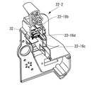
- a battery cover housing portion 22-16 (FIGS.
- the battery cover 30 is accommodated in the battery cover accommodating portion 22-16, which has a shape as shown in Fig. 9A (details will be described later), and the battery cover accommodating portion 22-16. Inside, it is slidable in the front-rear direction between a retracted position retracted with respect to the battery 16 (FIGS. 5 and 7) and an advanced position advanced with respect to the battery 16 (FIG. 8).
- the battery cover 30 When the battery 16 is attached to the battery housing space 28 of the punching machine main body 12, first, the battery cover 30 is pushed forward into the punching machine main body 12 and moved to the retracted position shown in FIG. Open the top of. Then, the battery 16 is inserted downward into the battery housing space 28 from the opened upper portion of the battery housing space 28. The battery 16 is moved downward while being guided by the battery guide 28-5, and is accommodated in the battery accommodating space 28 (FIG. 7). At this time, the male connection terminal 28-7 of the punching machine body 12 and the female connection terminal 16-5 of the battery 16 are connected, and the battery locking portion 16-4 provided on the battery 16 is connected to the intermediate wall portion.
- the battery 16 is held so as not to move by engaging with the battery locking recess 28-8 of 28-1, and the battery 16 is attached to the battery housing space 28.
- the battery cover 30 is pulled out from the perforator main body 12 toward the battery 16 and moved to the forward position shown in FIG. In this forward position, the battery cover 30 is located so as to cover a vertically extending gap formed between the intermediate wall 28-1 of the battery housing 22 and the front surface 16-1 of the battery 16 from above. Water or the like is prevented from entering the gap. Therefore, the risk that the chips, water, etc. enter the connection terminals 16-5 and 28-7 to cause a short circuit is reduced.
- the bottom wall 28-2 is slightly inclined downward from the front to the rear, so that even when water enters the battery housing space 28, the water is naturally discharged. Yes.
- the female connection terminal 16-5 of the battery 16 faces downward when the battery 16 is attached to the battery housing space 28, and water and dust are placed between the intermediate wall 28-1 and the water. Even if it enters from the gap, it is difficult to reach the female connection terminal 16-5.
- the battery cover 30 has an inclined surface 30-7 on the side facing the battery 16, and the inclined cover member 30-7 is formed in front of the upper surface of the battery 16 in the forward movement position of FIG. It abuts on the mating surface 16-6 (FIGS. 6 and 7).
- the inclined surface 16-3 of the battery locking portion 16-4 is pushed, and the battery 16 is moved upward while the battery locking portion 16-4 is housed in the battery 16.
- the battery cover 30 is pulled out from the battery accommodating space 28, but in a state where the battery cover 30 is in the forward position, the battery cover 30 interferes and the battery 16 cannot be pulled out and removed.
- a part of the battery cover 30 in the forward position is located on the moving path of the battery 16 when the battery 16 is pulled out from the battery housing space 28 and removed from the battery housing space 28.
- the battery 16 cannot be removed from the battery housing 22.
- it is necessary to pull out the battery 16 upward in a state where the battery cover 30 is pushed into the punching machine main body 12 and moved to the retracted position shown in FIG. As described above, the battery cover 30 restricts the movement of the battery 16 to prevent the battery 16 from being inadvertently removed.
- the battery cover 30 covers the inclined portion 16-3 of the battery 16 in the forward position so that the inclined portion 16-3 cannot be pushed, so that when the battery cover 30 is in the forward position, the battery locking portion 16- 4 cannot be released from the engagement with the battery locking recess 28-8.
- such a battery cover 30 in the present embodiment has a narrow sliding portion 30- located in the front (left side in the drawing) when viewed in the front-rear direction of the perforating machine 10. 1 and a cover portion 30-2 connected to the rear (right side in the figure) of the sliding portion 30-1 and wider than the sliding portion 30-1 Part 30-3.
- the cover portion 30-2 of the battery cover main body portion 30-3 is formed with arm portions 30-4 extending forward at both end portions, and projects outwardly from the tip of the arm portion 30-4.
- a convex locking portion 30-5 is formed.
- a switch engaging protrusion 30-6 that engages with a limit switch 32 described later is formed.
- the battery cover 30 is formed as an integral member of an elastic material such as resin, and the elongated arm portion 30-4 is elastically deformed, and the locking portion 30-5 at the tip thereof is laterally viewed (as viewed in the figure). In the vertical direction).
- the latching portion that can be displaced in the left-right direction is a concave first portion formed on the side surface of the battery cover housing portion 22-16 of the battery housing 22 when the battery cover 30 is in the retracted position.
- the battery cover 30 is prevented from inadvertently moving by engaging with the receiving portion 22-17.
- the arm portion 30-4 is elastically deformed and the locking portion is displaced inward, so that the first receiving of the locking portion 30-5 is performed.
- the engagement with the portion 22-17 is released, and the battery cover 30 can move toward the forward position.
- the locking portion 30-5 engages with the concave second receiving portion 22-18 formed on the side surface of the battery cover housing portion 22-16.
- the battery cover 30 is prevented from moving inadvertently.
- the arm portion 30-4 is elastically deformed and the locking portion 30-5 is displaced inward, so that the locking portion 30-5
- the engagement with the second receiving portion 22-18 is released, and the battery cover 30 can move toward the retracted position.
- the engaging portion 30-5 of the battery cover 30 and the first receiving portion 22-17 or the second receiving portion 22-18 of the battery housing 22 are engaged, so that the battery cover 30 is in the retracted position or the advanced position. Therefore, the battery cover 30 is prevented from being inadvertently moved due to, for example, vibration during drilling.
- the locking portion 30-5 of the battery cover 30 is convex, and the first receiving portion 22-17 and the second receiving portion 22-18 of the battery housing 22 are concave.
- the engaging portion 30-5 of the battery cover 30 may be concave, and the first receiving portion 22-17 and the second receiving portion 22-18 of the battery housing 22 may be convex. . Further, the engaging portion 30-5 of the battery cover 30 is configured not to be displaced in the left-right direction, and instead, the first receiving portion 22-17 and the second receiving portion 22-18 of the battery housing 22 are displaced in the left-right direction. It can be made to have the same function also by comprising. However, since the elastically deformed portion is more likely to be damaged than the other portions, considering the case where it is damaged, the battery cover 30 that can be easily replaced is provided with an elastically deforming portion. It is desirable to have it installed because it is easier to repair.
- the battery cover 130 according to another embodiment shown in FIG. 12 has a generally U-shaped battery cover locking member 130 in which an arm portion 130-4 having a locking portion 130-5 is connected to the connecting portion 130-6.
- the battery cover 30 shown in FIGS. 9A and 9B is different from the battery cover main body portion 130-3 including the sliding portion 130-1 and the cover portion 130-2. And different.
- the battery cover locking member 130-7 is formed by bending a thin member such as a spring material.
- the battery cover locking member 130-7 is attached to the inside of the battery cover main body 130-3 through an opening formed in the lower surface of the battery cover main body 130-3. 3, the locking portion 130-5 at the tip of the arm portion 130-4 protrudes laterally from the sliding portion 130-1 of the battery cover main body portion 130-3.
- the protruding locking portion 130-5 is engaged with the first receiving portion 22-17 and the second receiving portion 22-18 of the battery housing 22, so that the battery cover is similar to the battery cover 30 of FIGS. 9A and 9B.
- the position 130 can be locked to the retracted position and the advanced position.
- the battery cover locking member 130-7 constituting the elastically deformable arm portion 130-4 is separate from the battery cover main body portion 130-3, the battery cover 130 is relatively damaged. Only the easy arm part can be composed of a highly durable metal material, etc., and the durability of the arm part 130-4 is made higher than that integrally formed of resin, and the possibility of breakage is reduced. Is possible.
- the position of the locking portion 130-5 in the battery cover 130 is closer to the inside in the left-right direction than the position of the locking portion 30-5 of the battery cover 30 in FIGS. 9A and 9B.
- the side wall of the battery cover housing portion 22-16 is located closer to the inside than that shown in FIGS.
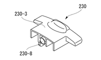
- a battery cover 230 according to still another embodiment shown in FIG. 13 includes a spring holding hole 230-8 that extends forward from the rear surface of the battery cover main body 230-3 and terminates in the middle.
- a spring 84 is set in the spring holding hole 230-8, and the spring 84 accommodates the end face 230-9 of the spring holding hole 230-8 and the battery cover of the battery housing 22.
- the compressed spring 84 urges the battery cover 230 in the direction from the retracted position to the advanced position.
- the battery cover 230 Since the battery cover 230 is held at the advanced position by the urging force of the spring 84, the arm portion having the locking portions 30-5 and 130-5 like the battery covers 30 and 130 according to the other embodiments described above. 30-4 and 130-4 are not provided. However, the battery cover 230 also includes arm portions 30-4 and 130-4 having locking portions 30-5 and 130-5 like the battery covers 30 and 130 according to other embodiments, The battery cover 230 may be held in the retracted position and the advanced position.
- a limit switch 32 is provided in the upper internal space 24-1 positioned above the internal space 24 formed between the frame 20 and the battery housing 22.
- the limit switch 32 is engaged with a switch engaging protrusion 30-6 provided so as to protrude downward at a portion of the battery cover 30 located in the battery housing 22, so that the battery cover 30 moves forward and backward. It is arranged so that it can be switched ON / OFF by the switch engagement protrusion 30-6 when it moves between the positions.
- the switch engagement protrusion 30-6 pushes the limit switch 32 to turn it on, retracts from the forward position and retracts into the battery housing 22
- the limit switch 32 is switched to OFF when moving toward the retracted position.
- This limit switch 32 is connected to a drive control circuit 36 disposed in the lower internal space 24-2, and functions as a battery cover position detecting means for detecting that the battery cover 30 has moved between the retracted position and the advanced position. To do. With such a configuration, it is possible to monitor whether the battery 16 is correctly attached, whether the battery 16 is in a state where it can be removed, etc. For example, the limit switch 32 is turned off and the battery cover 30 is turned off.
- the switch engagement protrusion 30-6 of the battery cover 30 has an opening 22 provided at a location constituting the lower step portion 22-16b of the battery cover housing portion 22-16 in the left portion 22-2 of the battery housing 22. It extends downward through ⁇ 16c (FIG. 17) and engages the limit switch 32. Further, the switch engaging protrusion 30-6 abuts on the rear end surface 22-16d of the opening 22-16c when the battery cover 30 is in the forward position, thereby limiting the movement range of the battery cover 30 and the battery cover. 30 is prevented from being detached from the battery cover housing portion 22-16.
- Such a structure is similarly provided in the battery covers 130 and 230 according to other embodiments.
- an LED display circuit 34 is also arranged in the upper internal space 24-1 located in the upper part of the internal space 24 formed between the battery housing 22 and the frame 20.
- This LED display circuit 34 is connected to a drive control circuit 36 and displays the state of the perforating machine 10 on the LED display unit 33 (FIG. 1) on the upper side of the battery housing 22 based on a signal from the drive control circuit 36. It is like that.
- the LED display circuit 34 has green, yellow, and red LEDs, and notifies the operator of the remaining amount of the battery 16 and the degree of load on the motor 48 by the blinking state of these LEDs.
- the LED display circuit 34 and the limit switch 32 and the drive control circuit 36 are electrically connected to each other by a wiring 35 covered with a shrinkable tube or the like.
- a partition plate 38 is provided in the battery housing 22 at a position between the drive control circuit 36, the LED display circuit 34, and the limit switch 32, and the lower internal space 24-2 in which the drive control circuit 36 is disposed is disposed in the LED. It is separated from the upper internal space 24-1 in which the display circuit 34 and the limit switch 32 are arranged. Specifically, as shown in FIG. 4, a right partition plate 38-1 provided in the right portion 22-1 of the battery housing 22 and a left partition plate 38-2 provided in the left portion 22-2 are interposed therebetween.
- the L-shaped seal member 39 is attached to the opening so as to be hermetically engaged with the L-shaped opening.
- a wiring insertion hole 39-1 is formed in the central portion of the seal member 39, and the wiring 35 connected to the LED display circuit 34 and the limit switch 32 is passed through the wiring insertion hole 39-1 so as to be sealed. It has become.
- the partition plate 38 is provided so as to be inclined downward from the rear to the front.
- a drain port 80 is formed in the front wall portion 20-1 of the frame 20 located in the upper internal space 24-1. Since the upper internal space 24-1 communicates with the battery cover housing portion 22-16 that slidably receives the battery cover 30 protruding to the outside of the battery housing 22, it is not sealed to the outside. Therefore, there is a risk that water such as rain may enter from the outside.
- the structure having the inclined partition plate 38 and the drainage port 80 as described above even when water enters the upper internal space 24-1, the water is discharged from the drainage port 80 to the outside, and the drive control circuit Water is prevented from entering the lower internal space 24-2 where 36 is located. Thereby, it is possible to prevent the drive control circuit 36 from being damaged due to getting wet.
- the upper surface of the lower surface wall portion 20-2 of the frame 20 is inclined downward from the front to the rear, and even if water enters the lower internal space 24-2, Water is discharged to the outside from a drain groove 20-13 provided at the rear end of 20-2.
- a perforation driving unit 14 is attached to the front surface of the front wall portion 20-1 of the frame 20.
- a drilling tool 44 such as a drill or an annular cutter is attached to and held by the arbor 40 below the drilling drive unit 14.
- the arbor 40 is connected to a motor 48 provided in a motor cover 46 of the drilling drive unit 14 via a reduction gear 45 inside the drilling drive unit 14.
- the drilling tool 44 is driven to rotate by driving the motor 48.
- a plurality of vent holes 52 are provided in the side surface 50 of the motor cover 46, and the motor 48 is cooled by air flowing into the inside from the vent holes 52.
- a plug 56 serving as a cutting oil injection port is provided on the left side surface of the drilling drive unit 14. By attaching a one-touch type socket with a hose to the plug 56, the cutting oil is added to the drilling tool 44 during drilling. To supply.
- dovetail grooves 62 extending in the vertical direction are formed on the left and right sides of the front surface of the front wall portion 20-1 of the frame 20.
- the perforation driving unit 14 is provided with a slider 63 whose left and right side edges have a shape corresponding to the shape of the dovetail groove 62.
- the slider 63 is provided with a rack 64 (FIG. 16), and the frame 20 is provided with a pinion 65 (FIG. 15) that engages with the rack 64.
- the slider 20 has a right side surface 20-10 (FIG. 2).
- the pinion 65 is rotated to move the drilling drive unit 14 up and down relative to the frame 20. Yes.
- the feed handle 66 can be attached to the end of the shaft 23-1 protruding from the left side surface 20-11 of the frame 20, and can be attached to either the right or left depending on the situation.
- the wiring 68 extending from the motor 48 of the drilling drive unit 14 passes through the dovetail groove 62 and the wiring insertion path 69 (FIGS. 15 and 16) formed in the slider 63, and as shown in FIG. It reaches the inside of the space 24 and is connected to the drive control circuit 36 so that it is hardly exposed to the outside. By preventing the wiring 68 from being exposed to the outside, it is possible to prevent the wiring 68 from being disconnected due to an excessive force such as the wiring 68 being caught.
- the electromagnet fixing portion 18 attached below the punching machine main body 12 generates a magnetic field by supplying electric power to the internal electromagnet 18-1, and is magnetically attracted to a magnetic material such as iron, so that the punching machine 10 Is designed to be fixedly held.
- a position adjusting mechanism 58 is provided between the electromagnet fixing portion 18 and the frame 20, and the electromagnet fixing portion 18 is perforated by turning a position adjusting handle 60 detachably attached to the position adjusting mechanism 58.
- the position of the machine main body 12 can be adjusted in the front / rear and left / right directions to finely adjust the drilling position of the workpiece.
- the position adjustment handle 60 can be attached to the right side surface of the position adjustment mechanism 58.
- an electromagnet switch 70 for activating the electromagnet fixing portion 18 is provided on the left side surface 22-15 of the battery housing 22.
- a wall 72 is provided around the electromagnet switch 70 to prevent the electromagnet switch 70 from being inadvertently operated.
- the electromagnet switch 70 is turned off when the rear side (left side as viewed in FIG. 1) is pressed, but the wall 72 is raised at the rear side. It is difficult to switch from ON to OFF.
- a motor switch 74 for starting the motor 48 is provided on the right side surface 22-14 of the battery housing 22.
- a wall 76 is also provided around the motor switch 74 so that the motor switch 74 is less likely to be inadvertently operated.
- the electromagnet switch 70 and the motor switch 74 By arranging the electromagnet switch 70 and the motor switch 74 on the side surfaces 22-14 and 22-15 on the left and right sides of the battery housing 22, it becomes easy to secure a place for arranging the switch. Therefore, the battery housing 22 can be designed to be small. In addition, erroneous operation of the electromagnet switch 70 and the motor switch 74 can be prevented.
- the battery cover 30 is provided so as to move between the retracted position and the advanced position with respect to the battery 16 by sliding linearly in the front-rear direction of the punching machine 10. It may be provided so as to be movable between the retracted position and the advanced position in another manner, such as pivoting. Further, when the battery cover 30 is in the forward position, the battery cover 30 is in contact with the battery 16. However, the battery cover 30 is not in contact with the battery 16 and may be in a position close to the battery 16. Good. Furthermore, the battery cover 30 does not necessarily have a function of holding the battery 16 so as not to be removed. When the battery 16 is moved upward from the battery housing space 28, the battery cover 30 is pushed by the battery 16 and moved backward. It may be configured to move to. In this embodiment, the limit switch 23 is adopted as the battery cover position detection means. However, the battery cover position detection means may be realized by using another form of sensor such as an optical switch.
- Drilling machine 10 Drilling machine body 12; Drilling drive unit 14; Battery 16; Front 16-1; Guide rail 16-2; Inclined surface 16-3; Battery locking part 16-4; Cover engaging surface 16-6; opening 16-6a; electromagnet fixing portion 18; electromagnet 18-1; frame 20; front wall portion 20-1; bottom wall portion 20-2; 20-4; handle mounting hole 20-8; engaging recess 20-9; right side surface 20-10; left side surface 20-11; drainage groove 20-13; screw hole 21; battery housing 22; ; Left portion 22-2; engagement protrusion 22-9; screw insertion hole 22-11; screw insertion hole 22-12; screw hole 22-13; right side surface 22-14; left side surface 22-15; Part 22-16; upper part 22-16a; lower part 2 -16b; opening 22-16c; rear end surface 22-16d; first receiving portion 22-17; second receiving portion 22-18; front wall 22-19; gear mechanism portion 23; shaft 23-1; Upper inner space 24-1; lower inner space 24-2; handle 26; right handle portion 26-1; left handle portion 26-2: screw 27;
Landscapes
- Engineering & Computer Science (AREA)
- Mechanical Engineering (AREA)
- Drilling And Boring (AREA)
- Battery Mounting, Suspending (AREA)
Abstract
Description
穿孔工具を回転駆動するためのモータを有する穿孔駆動部と、
前記モータに電力を供給するバッテリが取り付けられるバッテリ取付部を有し、前記穿孔工具を被加工物に対して近づけたり離したりするように前記穿孔駆動部を上下動可能に支持する穿孔機本体部と、
前記穿孔機本体部に取り付けられたバッテリカバーであって、前記バッテリ取付部に取り付けられた前記バッテリに対する後退位置と前進位置との間で移動可能とされ、前記前進位置においては、前記穿孔機本体部と前記バッテリとの間にできる隙間の少なくとも一部を覆うようにされたバッテリカバーと、を備える穿孔機を提供する。
前記穿孔機本体部が、前記バッテリカバーが前記後退位置にあるときに前記係止部と係合して前記バッテリカバーの摺動方向での移動を抑止する第1受部と、前記バッテリカバーが前記前進位置にあるときに前記係止部と係合して前記バッテリカバーの前記摺動方向での移動を抑止する第2受部とを有するようにすることができる。
前記バッテリカバーは、前記後退位置と前記前進位置との間で移動したときに、前記リミットスイッチのON/OFFを切り替えるようにすることができる。
Claims (10)
- 穿孔工具を回転駆動するためのモータを有する穿孔駆動部と、
前記モータに電力を供給するバッテリが取り付けられるバッテリ取付部を有し、前記穿孔工具を被加工物に対して近づけたり離したりするように前記穿孔駆動部を上下動可能に支持する穿孔機本体部と、
前記穿孔機本体部に取り付けられたバッテリカバーであって、前記バッテリ取付部に取り付けられた前記バッテリに対する後退位置と前進位置との間で移動可能とされ、前記前進位置においては、前記穿孔機本体部と前記バッテリとの間にできる隙間の少なくとも一部を覆うようにされたバッテリカバーと、を備える穿孔機。 - 前記バッテリカバーは、前記前進位置にあるときに、当該バッテリカバーの少なくとも一部が、前記バッテリ取付部に取り付けられた前記バッテリが当該バッテリ取付部から取り外されるときの前記バッテリの移動経路上に位置するようにされており、前記バッテリカバーが前記前進位置にある状態では前記バッテリを前記バッテリ取付部から取り外せないようにされた、請求項1に記載の穿孔機。
- 前記穿孔機本体部は、前記バッテリを前記バッテリ取付部から上方に動かすことにより前記バッテリ取付部から取り外せるような構造とされており、前記バッテリカバーは、前記前進位置にあるときに、前記穿孔機本体部と前記バッテリとの間にできる隙間をその上方位置から覆うようにした、請求項2に記載の穿孔機。
- 前記バッテリ取付部は、前記バッテリを上下方向で案内する上下方向に延びるバッテリガイドを有しており、前記バッテリは、該バッテリガイドに沿って下降することにより前記バッテリ取付部に取り付けられ、上昇することにより前記バッテリ取付部から取り外されるようにされている、請求項3に記載の穿孔機。
- 前記バッテリカバーが、前記穿孔機本体部に対して前記後退位置と前記前進位置との間で摺動可能に取り付けられている、請求項1乃至4の何れか一項に記載の穿孔機。
- 前記バッテリカバーが係止部を有し、
前記穿孔機本体部が、前記バッテリカバーが前記後退位置にあるときに前記係止部と係合して前記バッテリカバーの摺動方向での移動を抑止する第1受部と、前記バッテリカバーが前記前進位置にあるときに前記係止部と係合して前記バッテリカバーの前記摺動方向での移動を抑止する第2受部とを有するようにされた、請求項5に記載の穿孔機。 - 前記バッテリカバーが、前記摺動方向に延びる弾性変形可能なアーム部を有し、前記係止部が前記アーム部の先端に設けられている、請求項5に記載の穿孔機。
- 前記穿孔機本体部に配置され、前記バッテリカバーが前記後退位置と前記前進位置との間で移動したことを検知するバッテリカバー位置検出手段をさらに備える、請求項1に記載の穿孔機。
- 前記バッテリカバー位置検出手段がリミットスイッチを有し、
前記バッテリカバーは、前記後退位置と前記前進位置との間で移動したときに、前記リミットスイッチのON/OFFを切り替えるようにされている、請求項8に記載の穿孔機。 - 前記穿孔機本体部と前記バッテリカバーとの間に配置されたスプリングをさらに備え、該スプリングが前記バッテリカバーを前記後退位置から前記前進位置に向かう方向に付勢するようにされた、請求項1に記載の穿孔機。
Priority Applications (4)
| Application Number | Priority Date | Filing Date | Title |
|---|---|---|---|
| CN201480029883.7A CN105246626B (zh) | 2013-05-29 | 2014-05-28 | 蓄电池式穿孔机 |
| KR1020157036433A KR101799662B1 (ko) | 2013-05-29 | 2014-05-28 | 배터리식 천공기 |
| AU2014271763A AU2014271763B2 (en) | 2013-05-29 | 2014-05-28 | Battery-operated drilling machine |
| EP14804111.4A EP3006145B1 (en) | 2013-05-29 | 2014-05-28 | Drilling machine |
Applications Claiming Priority (2)
| Application Number | Priority Date | Filing Date | Title |
|---|---|---|---|
| JP2013-113112 | 2013-05-29 | ||
| JP2013113112A JP5952777B2 (ja) | 2013-05-29 | 2013-05-29 | バッテリ式穿孔機 |
Publications (1)
| Publication Number | Publication Date |
|---|---|
| WO2014192783A1 true WO2014192783A1 (ja) | 2014-12-04 |
Family
ID=51988808
Family Applications (1)
| Application Number | Title | Priority Date | Filing Date |
|---|---|---|---|
| PCT/JP2014/064059 Ceased WO2014192783A1 (ja) | 2013-05-29 | 2014-05-28 | バッテリ式穿孔機 |
Country Status (7)
| Country | Link |
|---|---|
| EP (1) | EP3006145B1 (ja) |
| JP (1) | JP5952777B2 (ja) |
| KR (1) | KR101799662B1 (ja) |
| CN (1) | CN105246626B (ja) |
| AU (1) | AU2014271763B2 (ja) |
| TW (1) | TWI547330B (ja) |
| WO (1) | WO2014192783A1 (ja) |
Cited By (2)
| Publication number | Priority date | Publication date | Assignee | Title |
|---|---|---|---|---|
| CN109301122A (zh) * | 2018-11-09 | 2019-02-01 | 潍坊歌尔电子有限公司 | 电池便捷拆装结构及头戴显示设备 |
| US11845178B2 (en) | 2020-11-03 | 2023-12-19 | Techtronic Cordless Gp | Modular work station |
Families Citing this family (8)
| Publication number | Priority date | Publication date | Assignee | Title |
|---|---|---|---|---|
| JP5948280B2 (ja) * | 2013-05-30 | 2016-07-06 | 日東工器株式会社 | バッテリ式穿孔機 |
| KR102159166B1 (ko) | 2014-05-09 | 2020-09-23 | 삼성전자주식회사 | 색분리 소자 및 상기 색분리 소자를 포함하는 이미지 센서 |
| AU2018292382B2 (en) * | 2017-06-26 | 2021-11-18 | Milwaukee Electric Tool Corporation | Cut-off saw |
| CN113042780B (zh) * | 2021-04-22 | 2023-04-28 | 广州信诺船舶服务有限公司 | 一种细长孔加工装置及其方法 |
| GB2610576A (en) | 2021-09-08 | 2023-03-15 | Black & Decker Inc | A power tool stand |
| GB2610578B (en) | 2021-09-08 | 2025-03-26 | Black & Decker Inc | A power tool stand |
| GB2619922B (en) * | 2022-06-20 | 2024-12-25 | Black & Decker Inc | A power tool stand |
| US12472619B2 (en) | 2024-01-22 | 2025-11-18 | Black & Decker Inc. | Power tool stand |
Citations (7)
| Publication number | Priority date | Publication date | Assignee | Title |
|---|---|---|---|---|
| JPH0230410A (ja) * | 1988-07-14 | 1990-01-31 | Mineo Takeuchi | 消雪ノズルの補修に用いる工事用機械 |
| JPH0735698A (ja) | 1993-07-19 | 1995-02-07 | Canon Inc | 像読取り装置、表面状態検査装置及び該装置を備える露光装置 |
| JPH09239677A (ja) * | 1996-03-08 | 1997-09-16 | Hitachi Koki Co Ltd | 蓄電池の保持装置 |
| JPH1128605A (ja) * | 1997-07-09 | 1999-02-02 | Nitto Kohki Co Ltd | 孔明け加工機 |
| JP2005074559A (ja) * | 2003-08-29 | 2005-03-24 | Nitto Kohki Co Ltd | 低丈型電動ドリル装置 |
| US20090028653A1 (en) | 2007-07-27 | 2009-01-29 | Wilbert Edward D | Ac/dc magnetic drill press |
| JP2011136407A (ja) * | 2009-12-29 | 2011-07-14 | Hitachi Koki Co Ltd | 電動工具 |
Family Cites Families (17)
| Publication number | Priority date | Publication date | Assignee | Title |
|---|---|---|---|---|
| JPS6031858Y2 (ja) * | 1980-04-22 | 1985-09-24 | 三菱電機株式会社 | 充電式携帯用電動工具 |
| JPS62123064U (ja) * | 1986-01-27 | 1987-08-05 | ||
| DE19905085A1 (de) * | 1999-01-29 | 2000-08-03 | Black & Decker Inc N D Ges D S | Batteriegetriebenes, handgeführtes Elektrowerkzeug |
| JP2002160110A (ja) * | 2000-11-27 | 2002-06-04 | Makita Corp | ドリルスタンド |
| DE10064173C1 (de) * | 2000-12-22 | 2002-06-13 | Rothenberger Werkzeuge Ag | Bohrmaschine mit Elektromotor für Gesteinsbohrer |
| CN1254353C (zh) * | 2001-05-21 | 2006-05-03 | 三菱麻铁里亚尔株式会社 | 钻孔装置及钻孔方法 |
| JP4043420B2 (ja) * | 2003-08-01 | 2008-02-06 | 日東工器株式会社 | 自動再駆動機能付き電動ドリル装置 |
| US7121773B2 (en) * | 2003-08-01 | 2006-10-17 | Nitto Kohki Co., Ltd. | Electric drill apparatus |
| JP2006281401A (ja) * | 2005-04-04 | 2006-10-19 | Hitachi Koki Co Ltd | コードレス電動工具 |
| SE531738C2 (sv) * | 2006-09-01 | 2009-07-28 | Husqvarna Ab | Borrmaskin |
| US9604284B2 (en) * | 2009-12-24 | 2017-03-28 | Nitto Kohki Co., Ltd. | Portable drilling machine |
| JP5556172B2 (ja) * | 2009-12-29 | 2014-07-23 | 日立工機株式会社 | ドリルビット |
| TWM412474U (en) * | 2010-12-10 | 2011-09-21 | Inventec Corp | Battery fixing module |
| CN202028801U (zh) * | 2011-01-01 | 2011-11-09 | 牛保明 | 可充电直流手电钻 |
| JP4793515B2 (ja) | 2011-04-18 | 2011-10-12 | マックス株式会社 | 電池パック及び電動工具 |
| JP6174432B2 (ja) * | 2013-03-29 | 2017-08-02 | 日東工器株式会社 | バッテリ式穿孔機 |
| JP5886786B2 (ja) * | 2013-05-08 | 2016-03-16 | 日東工器株式会社 | バッテリ式穿孔機 |
-
2013
- 2013-05-29 JP JP2013113112A patent/JP5952777B2/ja active Active
-
2014
- 2014-05-28 AU AU2014271763A patent/AU2014271763B2/en active Active
- 2014-05-28 TW TW103118627A patent/TWI547330B/zh active
- 2014-05-28 KR KR1020157036433A patent/KR101799662B1/ko active Active
- 2014-05-28 WO PCT/JP2014/064059 patent/WO2014192783A1/ja not_active Ceased
- 2014-05-28 CN CN201480029883.7A patent/CN105246626B/zh active Active
- 2014-05-28 EP EP14804111.4A patent/EP3006145B1/en active Active
Patent Citations (7)
| Publication number | Priority date | Publication date | Assignee | Title |
|---|---|---|---|---|
| JPH0230410A (ja) * | 1988-07-14 | 1990-01-31 | Mineo Takeuchi | 消雪ノズルの補修に用いる工事用機械 |
| JPH0735698A (ja) | 1993-07-19 | 1995-02-07 | Canon Inc | 像読取り装置、表面状態検査装置及び該装置を備える露光装置 |
| JPH09239677A (ja) * | 1996-03-08 | 1997-09-16 | Hitachi Koki Co Ltd | 蓄電池の保持装置 |
| JPH1128605A (ja) * | 1997-07-09 | 1999-02-02 | Nitto Kohki Co Ltd | 孔明け加工機 |
| JP2005074559A (ja) * | 2003-08-29 | 2005-03-24 | Nitto Kohki Co Ltd | 低丈型電動ドリル装置 |
| US20090028653A1 (en) | 2007-07-27 | 2009-01-29 | Wilbert Edward D | Ac/dc magnetic drill press |
| JP2011136407A (ja) * | 2009-12-29 | 2011-07-14 | Hitachi Koki Co Ltd | 電動工具 |
Cited By (3)
| Publication number | Priority date | Publication date | Assignee | Title |
|---|---|---|---|---|
| CN109301122A (zh) * | 2018-11-09 | 2019-02-01 | 潍坊歌尔电子有限公司 | 电池便捷拆装结构及头戴显示设备 |
| US11845178B2 (en) | 2020-11-03 | 2023-12-19 | Techtronic Cordless Gp | Modular work station |
| US12194612B2 (en) | 2020-11-03 | 2025-01-14 | Techtronic Cordless Gp | Modular work station |
Also Published As
| Publication number | Publication date |
|---|---|
| EP3006145B1 (en) | 2018-02-28 |
| KR101799662B1 (ko) | 2017-11-20 |
| TWI547330B (zh) | 2016-09-01 |
| AU2014271763A1 (en) | 2016-01-21 |
| TW201518011A (zh) | 2015-05-16 |
| JP2014231118A (ja) | 2014-12-11 |
| EP3006145A1 (en) | 2016-04-13 |
| KR20160010620A (ko) | 2016-01-27 |
| EP3006145A4 (en) | 2017-01-25 |
| JP5952777B2 (ja) | 2016-07-13 |
| AU2014271763B2 (en) | 2016-08-25 |
| CN105246626A (zh) | 2016-01-13 |
| CN105246626B (zh) | 2017-05-10 |
Similar Documents
| Publication | Publication Date | Title |
|---|---|---|
| JP5952777B2 (ja) | バッテリ式穿孔機 | |
| JP5948280B2 (ja) | バッテリ式穿孔機 | |
| US11305393B2 (en) | Dust collector and work tool provided with dust collector | |
| KR101807930B1 (ko) | 배터리식 천공기 | |
| GB2451566A (en) | AC/DC magnetic drill press | |
| AU2017202536B2 (en) | Battery-operated drilling machine | |
| EP2591887B1 (en) | Electric power tool | |
| JP6224922B2 (ja) | バッテリ式穿孔機 | |
| TWI540008B (zh) | driller |
Legal Events
| Date | Code | Title | Description |
|---|---|---|---|
| 121 | Ep: the epo has been informed by wipo that ep was designated in this application |
Ref document number: 14804111 Country of ref document: EP Kind code of ref document: A1 |
|
| WWE | Wipo information: entry into national phase |
Ref document number: 2014804111 Country of ref document: EP |
|
| NENP | Non-entry into the national phase |
Ref country code: DE |
|
| ENP | Entry into the national phase |
Ref document number: 20157036433 Country of ref document: KR Kind code of ref document: A |
|
| ENP | Entry into the national phase |
Ref document number: 2014271763 Country of ref document: AU Date of ref document: 20140528 Kind code of ref document: A |