WO2014196383A1 - 生体検知器、車両用着座検知器およびシートベルト非着用警告システム - Google Patents
生体検知器、車両用着座検知器およびシートベルト非着用警告システム Download PDFInfo
- Publication number
- WO2014196383A1 WO2014196383A1 PCT/JP2014/063709 JP2014063709W WO2014196383A1 WO 2014196383 A1 WO2014196383 A1 WO 2014196383A1 JP 2014063709 W JP2014063709 W JP 2014063709W WO 2014196383 A1 WO2014196383 A1 WO 2014196383A1
- Authority
- WO
- WIPO (PCT)
- Prior art keywords
- heat flux
- occupant
- living body
- flux sensor
- detected
- Prior art date
- Legal status (The legal status is an assumption and is not a legal conclusion. Google has not performed a legal analysis and makes no representation as to the accuracy of the status listed.)
- Ceased
Links
Images




Classifications
-
- B—PERFORMING OPERATIONS; TRANSPORTING
- B60—VEHICLES IN GENERAL
- B60R—VEHICLES, VEHICLE FITTINGS, OR VEHICLE PARTS, NOT OTHERWISE PROVIDED FOR
- B60R22/00—Safety belts or body harnesses in vehicles
- B60R22/48—Control systems, alarms, or interlock systems, for the correct application of the belt or harness
-
- B—PERFORMING OPERATIONS; TRANSPORTING
- B60—VEHICLES IN GENERAL
- B60N—SEATS SPECIALLY ADAPTED FOR VEHICLES; VEHICLE PASSENGER ACCOMMODATION NOT OTHERWISE PROVIDED FOR
- B60N2/00—Seats specially adapted for vehicles; Arrangement or mounting of seats in vehicles
- B60N2/002—Seats provided with an occupancy detection means mounted therein or thereon
- B60N2/0021—Seats provided with an occupancy detection means mounted therein or thereon characterised by the type of sensor or measurement
- B60N2/0022—Seats provided with an occupancy detection means mounted therein or thereon characterised by the type of sensor or measurement for sensing anthropometric parameters, e.g. heart rate or body temperature
-
- B—PERFORMING OPERATIONS; TRANSPORTING
- B60—VEHICLES IN GENERAL
- B60N—SEATS SPECIALLY ADAPTED FOR VEHICLES; VEHICLE PASSENGER ACCOMMODATION NOT OTHERWISE PROVIDED FOR
- B60N2/00—Seats specially adapted for vehicles; Arrangement or mounting of seats in vehicles
- B60N2/002—Seats provided with an occupancy detection means mounted therein or thereon
- B60N2/0021—Seats provided with an occupancy detection means mounted therein or thereon characterised by the type of sensor or measurement
- B60N2/0024—Seats provided with an occupancy detection means mounted therein or thereon characterised by the type of sensor or measurement for identifying, categorising or investigation of the occupant or object on the seat
- B60N2/0026—Seats provided with an occupancy detection means mounted therein or thereon characterised by the type of sensor or measurement for identifying, categorising or investigation of the occupant or object on the seat for distinguishing between humans, animals or objects
-
- B—PERFORMING OPERATIONS; TRANSPORTING
- B60—VEHICLES IN GENERAL
- B60N—SEATS SPECIALLY ADAPTED FOR VEHICLES; VEHICLE PASSENGER ACCOMMODATION NOT OTHERWISE PROVIDED FOR
- B60N2/00—Seats specially adapted for vehicles; Arrangement or mounting of seats in vehicles
- B60N2/002—Seats provided with an occupancy detection means mounted therein or thereon
- B60N2/0021—Seats provided with an occupancy detection means mounted therein or thereon characterised by the type of sensor or measurement
- B60N2/003—Seats provided with an occupancy detection means mounted therein or thereon characterised by the type of sensor or measurement characterised by the sensor mounting location in or on the seat
-
- B—PERFORMING OPERATIONS; TRANSPORTING
- B60—VEHICLES IN GENERAL
- B60R—VEHICLES, VEHICLE FITTINGS, OR VEHICLE PARTS, NOT OTHERWISE PROVIDED FOR
- B60R21/00—Arrangements or fittings on vehicles for protecting or preventing injuries to occupants or pedestrians in case of accidents or other traffic risks
- B60R21/01—Electrical circuits for triggering passive safety arrangements, e.g. airbags, safety belt tighteners, in case of vehicle accidents or impending vehicle accidents
- B60R21/015—Electrical circuits for triggering passive safety arrangements, e.g. airbags, safety belt tighteners, in case of vehicle accidents or impending vehicle accidents including means for detecting the presence or position of passengers, passenger seats or child seats, and the related safety parameters therefor, e.g. speed or timing of airbag inflation in relation to occupant position or seat belt use
- B60R21/01512—Passenger detection systems
-
- G—PHYSICS
- G01—MEASURING; TESTING
- G01K—MEASURING TEMPERATURE; MEASURING QUANTITY OF HEAT; THERMALLY-SENSITIVE ELEMENTS NOT OTHERWISE PROVIDED FOR
- G01K17/00—Measuring quantity of heat
-
- G—PHYSICS
- G01—MEASURING; TESTING
- G01K—MEASURING TEMPERATURE; MEASURING QUANTITY OF HEAT; THERMALLY-SENSITIVE ELEMENTS NOT OTHERWISE PROVIDED FOR
- G01K17/00—Measuring quantity of heat
- G01K17/06—Measuring quantity of heat conveyed by flowing media, e.g. in heating systems e.g. the quantity of heat in a transporting medium, delivered to or consumed in an expenditure device
- G01K17/08—Measuring quantity of heat conveyed by flowing media, e.g. in heating systems e.g. the quantity of heat in a transporting medium, delivered to or consumed in an expenditure device based upon measurement of temperature difference or of a temperature
- G01K17/20—Measuring quantity of heat conveyed by flowing media, e.g. in heating systems e.g. the quantity of heat in a transporting medium, delivered to or consumed in an expenditure device based upon measurement of temperature difference or of a temperature across a radiating surface, combined with ascertainment of the heat-transmission coefficient
-
- G—PHYSICS
- G01—MEASURING; TESTING
- G01V—GEOPHYSICS; GRAVITATIONAL MEASUREMENTS; DETECTING MASSES OR OBJECTS; TAGS
- G01V9/00—Prospecting or detecting by methods not provided for in groups G01V1/00 - G01V8/00
- G01V9/005—Prospecting or detecting by methods not provided for in groups G01V1/00 - G01V8/00 by thermal methods, e.g. after generation of heat by chemical reactions
-
- B—PERFORMING OPERATIONS; TRANSPORTING
- B60—VEHICLES IN GENERAL
- B60N—SEATS SPECIALLY ADAPTED FOR VEHICLES; VEHICLE PASSENGER ACCOMMODATION NOT OTHERWISE PROVIDED FOR
- B60N2210/00—Sensor types, e.g. for passenger detection systems or for controlling seats
- B60N2210/30—Temperature sensors
-
- B—PERFORMING OPERATIONS; TRANSPORTING
- B60—VEHICLES IN GENERAL
- B60N—SEATS SPECIALLY ADAPTED FOR VEHICLES; VEHICLE PASSENGER ACCOMMODATION NOT OTHERWISE PROVIDED FOR
- B60N2220/00—Computerised treatment of data for controlling of seats
- B60N2220/20—Computerised treatment of data for controlling of seats using a deterministic algorithm
-
- B—PERFORMING OPERATIONS; TRANSPORTING
- B60—VEHICLES IN GENERAL
- B60R—VEHICLES, VEHICLE FITTINGS, OR VEHICLE PARTS, NOT OTHERWISE PROVIDED FOR
- B60R22/00—Safety belts or body harnesses in vehicles
- B60R22/48—Control systems, alarms, or interlock systems, for the correct application of the belt or harness
- B60R2022/4808—Sensing means arrangements therefor
-
- G—PHYSICS
- G01—MEASURING; TESTING
- G01K—MEASURING TEMPERATURE; MEASURING QUANTITY OF HEAT; THERMALLY-SENSITIVE ELEMENTS NOT OTHERWISE PROVIDED FOR
- G01K2205/00—Application of thermometers in motors, e.g. of a vehicle
Definitions
- the present invention relates to a living body detector using a heat flux sensor, a vehicle seat detector, and a seat belt non-wear warning system.
- a vehicle seat detector used for a seat belt non-wearing warning system is known.
- This seating detector detects the weight applied to the seating surface of the seat, and determines whether or not an occupant is seated on the seat based on the detected weight.
- the above-described conventional living body detector when used, there is a possibility that an object is erroneously detected as a living body. Specifically, when a high-temperature object exists at a predetermined position, the detected temperature exceeds the predetermined temperature, and the high-temperature object is erroneously detected as a living body. Further, when the above-described vehicle seat detector is used, there is a possibility that an object is erroneously detected as an occupant. Specifically, when a heavy object is placed on the seat, the detected weight exceeds a predetermined weight, and the heavy object is erroneously detected as an occupant.
- the present invention has been made in view of the above problems, and has as its main purpose to realize accurate detection of a living body.
- the living body detector includes a heat flux sensor and determination means.
- the heat flux sensor is installed in a place where a heat flux emitted from a living body existing at a predetermined position can be detected.
- the determination unit compares the detection result of the heat flux sensor with a determination criterion set in advance according to the heat flux that can be detected when a living body exists at a predetermined position, and determines whether or not the living body exists at a predetermined position. Determine whether.
- the vehicle seating detector includes a heat flux sensor and seating determination means.
- the heat flux sensor is installed in a vehicle seat where a heat flux emitted from an occupant seated on the seat can be detected.
- the seating determination means compares the detection result of the heat flux sensor with a criterion set in advance according to the heat flux that can be detected when the occupant is seated on the seat, and the occupant is seated on the seat. It is determined whether or not.
- the detection result of the heat flux sensor differs between when the heat flux emitted from the living body is detected and when the heat flux emitted from the object is detected. For example, when the heat flux emitted from a living body is compared with the heat flux emitted from a high-temperature object, the size of the heat flux, the change in heat flux with time, and the like are different.
- the living body detector and the vehicle seating detector according to the present invention can accurately detect the presence or absence of a living body or an occupant by making a determination based on a comparison between a detection result of the heat flux sensor and a determination criterion.
- the heat flux sensor has a plurality of first and second via holes penetrating in the thickness direction in an insulating base member made of a thermoplastic resin.
- the first and second connection members formed of different metals are embedded in the first and second via holes, and the first and second connection members are alternately connected in series.
- at least one of the metals forming the first and second connecting members is a sintered alloy obtained by sintering a plurality of metal atoms while maintaining the crystal structure of the metal atoms.
- the living body detector and the vehicle seating detector according to the present invention can detect the presence or absence of a living body or an occupant more accurately by using a highly sensitive heat flux sensor.
- FIG. 1 It is a schematic diagram which shows the structure of the seat detector for vehicles which concerns on 1st Embodiment. It is a schematic diagram of the vehicle seat 1 in FIG. 1, (a) shows the state of the vehicle seat 1 before the occupant is seated, (b) when the occupant is seated, and (c) shows the state after the occupant is seated. It is a top view of the heat flux sensor in FIG. FIG. 4 is a sectional view taken along line IV-IV in FIG. 3.
- FIG. 5 is a sectional view taken along line VV in FIG. 3.
- FIG. 10 is a schematic diagram for explaining a first threshold value qth1, a second threshold value qth2, a third threshold value qth3, and a fourth threshold value qth4 in FIG. It is a schematic diagram which shows the structure of the health condition abnormality detection system which concerns on 2nd Embodiment.
- the living body detector of the present invention is applied to a vehicle seat detector used in a seat belt non-wear warning system.
- a seat belt non-wear warning system for a passenger seat of a vehicle will be described.
- the seat belt non-wearing warning system includes a heat flux sensor 10 provided in the vehicle seat 1, a control unit 20, a seat belt buckle switch 1 c, an unillustrated indicator lamp and buzzer. Mainly prepared.
- the heat flux sensor 10 is installed inside the seat portion 1a of the vehicle seat 1. As shown in FIG. As shown in FIG. 2B, the heat flux sensor 10 detects a heat flux that passes through the heat flux sensor 10 in the thickness direction, and a passenger is seated on the vehicle seat 1. The heat flux emitted from the passenger toward the seat 1a is detected. In this way, the heat flux sensor 10 is installed at a position where it can detect the heat flux emitted toward the inside of the seat portion 1a from the buttocks of the occupant seated on the vehicle seat 1.
- the insulating base member 100, the front surface protection member 110, and the back surface protection member 120 are integrated, and the first and second connections are made inside the integrated body.
- the members 130 and 140 are alternately connected in series.
- the structure of the heat flux sensor 10 will be specifically described below.
- the surface protection member 110 is omitted for easy understanding.
- FIG. 3 is not a cross-sectional view, the first and second connection members 130 and 140 are hatched for easy understanding.
- the insulating base member 100 is composed of a planar rectangular thermoplastic resin film typified by polyetheretherketone (PEEK), polyetherimide (PEI), liquid crystal polymer (LCP) and the like. .
- the insulating base member 100 is formed in a staggered pattern so that a plurality of first and second via holes 101 and 102 penetrating in the thickness direction are alternately arranged.
- the first and second via holes 101 and 102 of the present embodiment are cylindrical with a constant diameter from the front surface 100a to the back surface 100b of the insulating base member 100, but from the front surface 100a to the back surface 100b. You may be made into the taper shape where a diameter becomes small toward it. Moreover, it may be made into the taper shape where a diameter becomes small toward the surface 100a from the back surface 100b, and you may be made into the square tube shape.
- the first connection member 130 is disposed in the first via hole 101, and the second connection member 140 is disposed in the second via hole 102. That is, the first and second connection members 130 and 140 are alternately arranged on the insulating base member 100.
- the first and second connection members 130 and 140 are disposed in the first and second via holes 101 and 102, the number, size, interval, and the like of the first and second via holes 101 and 102 are set. By appropriately changing, the first and second connection members 130 and 140 can be arranged with high density. As a result, the electromotive voltage can be increased, and high sensitivity of the heat flux sensor 10 can be ensured.
- the first and second connection members 130 and 140 are made of different metals so as to exhibit the Seebeck effect.
- the first connecting member 130 is a metal compound obtained by solid-phase sintering a Bi—Sb—Te alloy powder constituting a P-type semiconductor so as to maintain a crystal structure of a plurality of metal atoms before sintering. Composed.
- the second connecting member 140 is made of a metal compound obtained by solid-phase sintering the Bi—Te alloy powder constituting the N-type semiconductor so as to maintain the crystal structure of a plurality of metal atoms before sintering.
- the metal forming the first and second connection members 130 and 140 is a sintered alloy obtained by sintering a plurality of metal atoms while maintaining the crystal structure of the metal atoms.
- the electromotive voltage generated in the first and second connection members 130 and 140 alternately connected in series can be increased, and high sensitivity of the heat flux sensor 10 can be secured.
- a highly sensitive heat flux sensor is used, it is possible to accurately detect a living body using the heat flux sensor.
- a member 110 On the surface 100a of the insulating base member 100, surface protection composed of a flat rectangular thermoplastic resin film typified by polyetheretherketone (PEEK), polyetherimide (PEI), liquid crystal polymer (LCP), etc.
- PEEK polyetheretherketone
- PEI polyetherimide
- LCP liquid crystal polymer
- a member 110 is disposed.
- the surface protection member 110 has the same planar shape as the insulating base member 10, and a plurality of surface patterns 111 patterned with copper foil or the like on the one surface 110 a side facing the insulating base member 100 are separated from each other. Is formed.
- Each surface pattern 111 is appropriately electrically connected to the first and second connection members 130 and 140, respectively.
- first connecting member 130 and one second connecting member 140 when one adjacent first connecting member 130 and one second connecting member 140 are set as one set 150, the first and second connections of each set 150.
- the members 130 and 140 are connected to the same surface pattern 111. That is, the first and second connection members 130 and 140 of each set 150 are electrically connected via the surface pattern 111.
- one first connection member 130 and one second connection member 140 that are adjacent along the longitudinal direction of the insulating base member 100 (the left-right direction in FIG. 4) are combined into one set 150. ing.
- a flat rectangular back surface protection composed of a thermoplastic resin film typified by polyether ether ketone (PEEK), polyether imide (PEI), liquid crystal polymer (LCP), etc.
- a member 120 is disposed.
- the length of the insulating base member 100 in the longitudinal direction is longer than that of the insulating base member 100, and the back surface 100 b of the insulating base member 100 so that both end portions in the longitudinal direction protrude from the insulating base member 100. Is arranged.
- the back surface protection member 120 is formed with a plurality of back surface patterns 121 patterned with copper foil or the like on the one surface 120a side facing the insulating base member 100 so as to be separated from each other. Each back pattern 121 is appropriately electrically connected to the first and second connecting members 130 and 140, respectively.
- the first connection member 130 of one set 150 and the second connection member 140 of the other set 150 are connected to the same back surface pattern 121. That is, the first and second connection members 130 and 140 are electrically connected through the same back surface pattern 121 across the set 150.
- the first and second connecting members 130 and 140 that are adjacent along the width direction (vertical direction in FIG. 3) perpendicular to the longitudinal direction are the same at the outer edge of the insulating base member 100.
- the back surface pattern 121 is connected. More specifically, the first and second connecting members 130 and 140 are connected in series in the longitudinal direction of the insulating base member 100 via the front surface pattern 111 and the back surface pattern 121 so that the connected body is folded back. The first and second connection members 130 and 140 are connected to the same back surface pattern 121.
- both end portions of the back surface pattern 121 positioned at both ends of the connection body in which all the first and second connection members 130 and 140 are connected in series as described above are shown in FIGS. 3 and 4.
- the insulating base member 100 is formed so as to be exposed. Then, both end portions of the back surface pattern 121 exposed from the insulating base member 100 function as terminals connected to the control unit 20.
- the above is the configuration of the basic heat flux sensor 10 in the present embodiment.
- the heat flux sensor 10 outputs a sensor signal (electromotive voltage) corresponding to the heat flux passing through the heat flux sensor 10 in the thickness direction to the control unit 20.
- a sensor signal electromotive voltage generated in the first and second connection members 130 and 140 alternately connected in series changes.
- the thickness direction of the heat flux sensor 10 coincides with the stacking direction of the insulating base member 100, the front surface protection member 110, and the back surface protection member 120.
- an insulating base member 100 is prepared, and a plurality of first via holes 101 are formed by a drill, a laser, or the like.
- each first via hole 101 is filled with a first conductive paste 131.
- a method (apparatus) for filling the first via hole 101 with the first conductive paste 131 the method (apparatus) described in Japanese Patent Application No. 2010-50356 by the present applicant may be adopted.
- the insulating base member 100 is disposed on a holding table (not shown) through the suction paper 160 so that the back surface 100 b faces the suction paper 160. Then, the first conductive paste 131 is filled into the first via hole 101 while the first conductive paste 131 is melted. As a result, most of the organic solvent of the first conductive paste 131 is adsorbed by the adsorption paper 160, and the alloy powder is placed in close contact with the first via hole 101.
- the adsorbing paper 160 may be made of a material that can absorb the organic solvent of the first conductive paste 131, and general high-quality paper or the like is used.
- the first conductive paste 131 is a paste obtained by adding an organic solvent such as paraffin having a melting point of 43 ° C. to a powder of Bi—Sb—Te alloy in which metal atoms maintain a predetermined crystal structure. Used. For this reason, when the first conductive paste 131 is filled, the surface 100a of the insulating base member 100 is heated to about 43 ° C.
- a plurality of second via holes 102 are formed in the insulating base member 100 by a drill, a laser, or the like. As described above, the second via holes 102 are alternately arranged with the first via holes 101 and are formed so as to form a staggered pattern together with the first via holes 101.
- the second conductive paste 141 is filled in each second via hole 102. This step can be performed in the same step as in FIG.
- the insulating base member 100 is again disposed on the holding table (not shown) via the suction paper 160 so that the back surface 100b faces the suction paper 160, and then the second conductive paste 141 is filled in the second via hole 102. To do. As a result, most of the organic solvent of the second conductive paste 141 is adsorbed by the adsorption paper 160, and the alloy powder is placed in close contact with the second via hole 102.
- the second conductive paste 141 is a Bi-Te alloy powder in which metal atoms different from the metal atoms constituting the first conductive paste 131 maintain a predetermined crystal structure, and an organic solvent such as terpine having a melting point of room temperature. A paste made by adding is used. That is, the organic solvent constituting the second conductive paste 141 has a lower melting point than the organic solvent constituting the first conductive paste 131.
- the second conductive paste 141 is filled, the surface 100a of the insulating base member 100 is maintained at room temperature. In other words, the second conductive paste 141 is filled with the organic solvent contained in the first conductive paste 131 solidified. This suppresses the second conductive paste 141 from being mixed into the first via hole 101.
- the state in which the organic solvent contained in the first conductive paste 131 is solidified means that the organic solvent remaining in the first via hole 101 without being adsorbed by the adsorption paper 160 in the process of FIG. That is.
- one surface 110a, 120a of the surface protection member 110 and the back surface protection member 120 that faces the insulating base member 100 A copper foil or the like is formed. Then, by appropriately patterning this copper foil, the surface protection member 110 formed with a plurality of surface patterns 111 spaced apart from each other, and the back surface protection member 120 formed with a plurality of back surface patterns 121 spaced apart from each other. prepare.
- the back surface protection member 120, the insulating base member 100, and the surface protection member 110 are sequentially stacked to form a stacked body 170.
- the back surface protection member 120 is longer in the longitudinal direction than the insulating base member 100. And the back surface protection member 120 is arrange
- the laminated body 170 is disposed between a pair of press plates (not shown), and is pressed while being heated in a vacuum state from the upper and lower surfaces in the laminating direction. Integrate. Specifically, the first and second conductive pastes 131 and 141 are solid-phase sintered to form the first and second connection members 130 and 140, and the first and second connection members 130 and 140 and the surface The laminated body 170 is integrated by applying pressure while heating so that the pattern 111 and the back surface pattern 121 are connected.
- a cushioning material such as rock wool paper may be disposed between the laminate 170 and the press plate. As described above, the heat flux sensor 10 is manufactured.
- the seat belt buckle switch 1c is a detecting unit that detects a non-wearing state of the seat belt 1b, and is turned on when the seat belt 1b is worn, and outputs a switch signal to the control unit 20.
- the indicator lamp and the buzzer are notifying means for notifying the occupant when the seat belt 1b is not worn.
- the control unit 20 is an electronic control device composed of, for example, a microcomputer, a memory as storage means, and its peripheral circuits, and performs predetermined arithmetic processing according to a preset program to operate the indicator lamp and the buzzer. Control.
- control unit 20 executes the control process shown in FIG.
- This control process is executed when the ignition switch or the engine start switch is turned on, or when the vehicle is traveling at a certain speed or higher.
- This control process is repeatedly executed at predetermined time intervals. Note that each control step in FIG. 7 constitutes various function realizing means possessed by the control unit 2.
- the control unit 20 first performs human body presence / absence determination processing for determining the presence / absence of an occupant (human body) sitting on the vehicle seat 1 (step S1).
- This step S1 corresponds to the determination means and the seating determination means described in the claims of the present application. Details of this processing will be described later.
- step S2 determines whether or not the passenger is wearing a seat belt is determined.
- step S3 corresponds to the seat belt wearing determination means described in the claims of the present application.
- step S4 When it is determined that the occupant is not wearing the seat belt 1b, an operation instruction signal is output to the notification means to warn the occupant that the seat belt is not worn (step S4). Specifically, the buzzer generates a warning sound and the indicator lamp lights or blinks. This step S4 corresponds to the warning means described in the claims of the present application. On the other hand, when it determines with the passenger
- step S1 the human body presence / absence determination process in step S1 will be described.
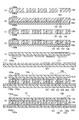
- the states 1, 2, and 3 in FIG. 8 are the states before the occupant is seated as shown in FIG. 2A, the occupants are seated as shown in FIG. 2B, and FIG. This corresponds to the state where the occupant shown in FIG. FIG. 8 shows a case where the body temperature of the occupant is higher than that of the vehicle seat 1.
- the heat flux emitted from the object is placed on the vehicle seat 1 as shown by the broken line in FIG. Immediately after, it decreases toward 0 with time. At this time, if the temperature of the object is different from the body temperature, the size of the detected heat flux is different from the heat flux emitted from the human body. In addition, in the case of an object and in the case of a human body, if the thermal conductivity is different, the rate of change (slope) of the heat flux with time is different.
- step S1 it is determined whether or not the detected heat flux is a heat flux emitted from a living body, and when the detected heat flux is a heat flux emitted from a living body, Judge that there is. That is, the detection result of the heat flux sensor 10 is compared with a criterion set in advance according to the heat flux that can be detected when an occupant is seated on the vehicle seat 1, and the detection result satisfies the criterion. In this case, it is determined that there is a human body.
- a change tendency of the heat flux with the passage of time is obtained based on a sensor signal from the heat flux sensor 10 that is intermittently or continuously input.
- the change tendency of heat flux here is a curve showing the change of heat flux as shown in FIG.
- a map indicating a range in which the heat flux can be changed with time when an occupant is seated is used as a criterion. This map is created in advance by experiments or the like.
- the heat flux from the human body varies from person to person, and even the same person varies depending on the health condition. Set the judgment criteria to be used for judgment. And when the change tendency of the calculated
- the heat flux detection starts.
- the heat flux is calculated immediately after the first and second predetermined times (time t1, t2).
- time t1, t2 the first and second predetermined times
- the curve indicated by the solid line in FIG. 10 corresponds to the state 2 of the solid line in FIG.
- the time immediately after the start of detection of the heat flux by the heat flux sensor 10 is defined as time t0
- the time after the first and second predetermined time immediately after the start of detection of the heat flux is defined as times t1 and t2.
- the time when the heat flux detected by the heat flux sensor 10 becomes a substantially constant value after decreasing from the value immediately after the start of detection. .
- the first range of heat flux that can be detected at time t0 is set to qth1 or less and qth2 or more
- the second range of heat flux that can be detected at times t1 and t2 is set to qth3 or less and qth4 or more.
- the heat flux from the human body varies from person to person and from person to person. Two ranges are set.
- control part 2 performs the control process shown in FIG. 9 using the criterion shown in this FIG. Note that each control step in FIG. 9 constitutes various function realizing means possessed by the control unit 2.
- step S11 a sensor signal (voltage value) output from the heat flux sensor 10 is read to determine whether or not the voltage value V0 is larger than the threshold value Vth. Thereby, it is determined whether the heat flux is detected by the heat flux sensor 10 or not.
- the control unit 2 makes an affirmative determination (YES), Proceed to step S12.
- the process proceeds to step S19, it is determined that there is no human body, and the process proceeds to step S2.
- step S12 the heat flux is calculated based on the voltage value V0 read in step S11.
- the heat flux at this time is defined as a heat flux q0 at time t0.
- step S13 it is determined whether or not the heat flux q0 is within the first range. That is, it is determined whether or not the heat flux q0 is equal to or lower than the first threshold value qth1 and equal to or higher than the second threshold value qth2 (qth1 ⁇ q0 ⁇ qth2).
- the process proceeds to step S19, it is determined that there is no human body, and the process proceeds to step S2. move on.
- step S14 it is determined whether or not the heat flux q0 is within the first range. That is, it is determined whether or not the heat flux q0 is equal to or lower than the first threshold value qth1 and equal to or higher than the second threshold value qth2 (qth1 ⁇ q0 ⁇ qth2).
- step S14 the sensor signal at time t1 after the elapse of the first predetermined time from time t0 is read, and the heat flux q1 at time t1 is calculated based on the read sensor signal.
- step S15 it is determined whether or not the heat flux q1 is within the second range. That is, it is determined whether or not the heat flux q1 is not more than the third threshold value qth3 and not less than the fourth threshold value qth4 (qth3 ⁇ q1 ⁇ qth4).
- the process proceeds to step S19, it is determined that there is no human body, and the process proceeds to step S2. move on.
- step S16 it is determined whether or not the heat flux q1 is within the second range. That is, it is determined whether or not the heat flux q1 is not more than the third threshold value qth3 and not less than the fourth threshold value qth4 (qth3 ⁇ q1 ⁇ qth4).
- step S16 the sensor signal at time t2 after the elapse of the second predetermined time from time t0 is read, and the heat flux q2 at time t2 is calculated based on the read sensor signal.
- step S17 it is determined whether or not the heat flux q2 is within the second range. That is, it is determined whether or not the heat flux q2 is equal to or less than the third threshold value qth3 and equal to or greater than the fourth threshold value qth4 (qth3 ⁇ q2 ⁇ qth4).
- This second range is the same as that used in step S15. This is because, as shown in FIG. 10, when an occupant is seated on the vehicle seat 1, the magnitude of the heat flux after a predetermined time immediately after sitting is substantially constant at a predetermined size.
- step S17 the process proceeds to step S19, where it is determined that there is no human body, and the process proceeds to step S2.
- step S18 the process proceeds to step S18, where it is determined that there is a human body in the vehicle seat 1, and the process proceeds to step S2.
- the present embodiment it is possible to avoid erroneously detecting a high-temperature object as a human body, and it is possible to accurately detect the human body.
- crew is seated in the vehicle seat 1 changes with the temperature of the vehicle seat 1, it changes a criterion according to the temperature of the vehicle seat 1. Is preferred.
- the insulating base member 100, the surface protection member 110, and the back surface protection member 120 are configured using a thermoplastic resin and have flexibility.
- the heat flux sensor 10 of the present embodiment has flexibility, so that the sitting comfort does not deteriorate.
- the living body detector of the present invention is applied to a health condition abnormality detection system.
- This abnormality detection system notifies the outside when it is determined that the health state of the human body in the house is abnormal.
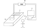
- the abnormality detection system mainly includes a plurality of heat flux sensors 10, a control unit 20, and notification means (not shown).
- the heat flux sensor 10 has the same configuration as that of the first embodiment.
- the heat flux sensor 10 is installed on an object with which a person comes into contact, for example, the bed 2 or the sitting chair 3 when the person lives in the house.
- the object which a person contacts includes a cushion, a door knob, a toilet seat, and the like.
- the heat flux sensor 10 detects a heat flux emitted from a human body when a human body is present at a predetermined position, that is, the bed 2, the chair 3 and the like.
- Each heat flux sensor 10 outputs a sensor signal corresponding to the heat flux to the control unit 20.
- the control unit 20 executes a human body presence / absence determination process similar to that of the first embodiment for each of the plurality of heat flux sensors 10 to determine the presence / absence of a human body at the location where the heat flux sensor 10 is installed. Then, based on the determination result for each heat flux sensor 10, it is determined whether or not the health state of the target person is abnormal. As a result, when it is determined that there is an abnormality, the notification means is activated.
- the notification means is, for example, a communication device that sends an e-mail to the outside that the health status of the target person is abnormal.
- the target person when the target person is healthy, the person moves in the house, and thus the human body is detected by each heat flux sensor 10.
- the heat flux installed in the bed 2 A human body is detected only by the sensor 10, or a human body is not detected by any of the heat flux sensors 10.
- control unit 20 determines whether or not the number of the heat flux sensors 10 in which the human body is detected is 1 or less, and the number of the heat flux sensors 10 in which the human body is detected is 1 or 0.
- the control unit 20 determines whether or not the number of the heat flux sensors 10 in which the human body is detected is 1 or less, and the number of the heat flux sensors 10 in which the human body is detected is 1 or 0.
- the human body presence / absence determination process similar to that of the first embodiment is executed, it is possible to avoid erroneously detecting a high-temperature object as a human body and to accurately detect a human body.
- the insulating base member 100, the surface protection member 110, and the back surface protection member 120 are configured using a thermoplastic resin and have flexibility. For this reason, according to the shape of an installation location, the heat flux sensor 10 can be deform
- the living body detector of the present invention is applied to a seating detector used in a seat belt non-wearing warning system.
- another vehicle seating detector for example, an occupant is seated.
- the present invention can also be applied to a seating detector used in a vehicle air conditioner that selectively blows conditioned air toward a seat.
- the presence or absence of a human body is determined based on the heat flux detected by the heat flux sensor 10, but it is also possible to determine what state the human body is. is there. That is, as shown in FIG. 8, the heat flux from the human body is detected in the normal steady state (solid line in FIG. 8) and the other states (dotted line and two-dot chain line in FIG. 8). The changing tendency of heat flux is different.
- the heat flux change in the steady state of the target person is examined in advance, and the change tendency of the heat flux is used as a judgment criterion. Then, by comparing the change tendency of the heat flux detected by the heat flux sensor 10 with the judgment criteria, it is possible to detect the life / death state, the presence / absence of illness, and the presence / absence of sleepiness of the target person. is there.
- the installation location of the heat flux sensor is a living body contact object, but the installation location of the heat flux sensor is not limited to the living body contact object, and the heat flux emitted from the living body is It may be a place away from the living body as long as it can be detected.
- control unit 2 calculates the heat flux based on the electromotive voltage (voltage value) generated by the heat flux sensor 10, but the current (current value) generated by the heat flux sensor 10. Based on the above, the heat flux may be calculated. In short, the control unit 2 can detect the heat flux based on the electromotive force generated by the heat flux sensor 10.
- the metal forming the first and second connecting members 130 and 140 is a Bi—Sb—Te alloy and a Bi—Te alloy, respectively. Also good.
- both of the metals forming the first and second connecting members 130 and 140 are solid-phase sintered sintered alloys, but at least one of them is solid-phase sintered. Any sintered alloy may be used. As a result, the electromotive force can be increased and the sensitivity of the heat flux sensor 10 can be increased compared to the case where both of the metals forming the first and second connection members 130 and 140 are not sintered solid-sintered. Is possible.
Landscapes
- Engineering & Computer Science (AREA)
- Mechanical Engineering (AREA)
- Transportation (AREA)
- Aviation & Aerospace Engineering (AREA)
- Physics & Mathematics (AREA)
- General Physics & Mathematics (AREA)
- Chemical & Material Sciences (AREA)
- Combustion & Propulsion (AREA)
- Geophysics (AREA)
- General Life Sciences & Earth Sciences (AREA)
- Life Sciences & Earth Sciences (AREA)
- Chemical Kinetics & Catalysis (AREA)
- Automation & Control Theory (AREA)
- Health & Medical Sciences (AREA)
- Cardiology (AREA)
- General Health & Medical Sciences (AREA)
- Heart & Thoracic Surgery (AREA)
- Chair Legs, Seat Parts, And Backrests (AREA)
- Geophysics And Detection Of Objects (AREA)
- Seats For Vehicles (AREA)
- Measuring Temperature Or Quantity Of Heat (AREA)
Abstract
Description
本実施形態は、本発明の生体検知器をシートベルト非着用警告システムに用いられる車両用着座検知器に適用したものである。本実施形態では、車両の助手席用のシートベルト非着用警告システムについて説明する。
(ステップS4)。具体的に、ブザーが警告音を発生させるとともに、表示灯が点灯または点滅する。このステップS4が、本願の特許請求の範囲に記載の警告手段に対応する。一方、乗員がシートベルト1bを着用していると判定された場合、ステップS4を実行せず、終了する。そして、再び、図7に示す制御処理が実行される。
なお、図8中一点鎖線、二点鎖線で示されるように、人体からの熱流束は、人によって異なったり、同じ人でも健康状態によって異なったりするので、これを考慮して、人体の有無を判定する際に用いる判定基準を設定する。そして、求められた熱流束の変化傾向がマップに適合した場合に、車両用シート1に人体有りと判定する。
本実施形態は、本発明の生体検知器を健康状態異常検知システムに適用したものである。この異常検知システムは、家の中にいる人体の健康状態が異常であると判定した場合に、外部に報知するものである。
以上、本発明の実施形態について説明したが、本発明は上記実施形態に限定されるものではなく、本発明の要旨を逸脱しない範囲において、様々な態様にて実施することが可能である。
20 制御部
100 絶縁ベース部材
101、102 第1、第2ビアホール
130、140 第1、第2接続部材
Claims (3)
- 所定位置に存在する生体から発せられる熱流束を検出可能な場所に設置される熱流束センサ(10)と、
所定位置に生体が存在するか否かを判定する判定手段(S1)とを備え、
前記熱流束センサは、熱可塑性樹脂からなる絶縁ベース部材(100)にその厚さ方向に貫通する複数の第1、第2ビアホール(101、102)が形成されていると共に、前記第1、第2ビアホールに互いに異なる金属で形成された第1、第2接続部材(130、140)が埋め込まれ、前記第1、第2接続部材が交互に直列接続された構造を有し、
前記第1、第2接続部材を形成する前記金属の少なくとも一方は、複数の金属原子が当該金属原子の結晶構造を維持した状態で焼結された焼結合金であり、
前記判定手段は、前記熱流束センサの検出結果と、所定位置に生体が存在する場合に検出されうる熱流束に応じて予め設定された判定基準とを比較して、所定位置に生体が存在するか否かを判定することを特徴とする生体検知器。 - 車両用シート(1)において該シートに着座している乗員から発せられる熱流束を検出可能な場所に設置される熱流束センサ(10)と、
前記車両用シートに乗員が着座しているか否かを判定する着座判定手段(S1)とを備え、
前記熱流束センサは、熱可塑性樹脂からなる絶縁ベース部材(100)にその厚さ方向に貫通する複数の第1、第2ビアホール(101、102)が形成されていると共に、前記第1、第2ビアホールに互いに異なる金属で形成された第1、第2接続部材(130、140)が埋め込まれ、前記第1、第2接続部材が交互に直列接続された構造を有し、
前記第1、第2接続部材を形成する前記金属の少なくとも一方は、複数の金属原子が当該金属原子の結晶構造を維持した状態で焼結された焼結合金であり、
前記着座判定手段は、前記熱流束センサの検出結果と、前記車両用シートに乗員が着座している場合に検出されうる熱流束に応じて予め設定された判定基準とを比較して、前記車両用シートに乗員が着座しているか否かを判定することを特徴とする車両用着座検知器。 - 請求項2に記載の車両用着座検知器と、
該車両用着座検知器の着座判定手段(S1)により前記車両用シートに乗員が着座していると判定された場合に、該乗員がシートベルトを着用しているか否かを判定するシートベルト着用判定手段(S3)と、
前記シートベルト着用判定手段(S3)により前記乗員がシートベルトを着用していないと判定された場合に、該乗員にシートベルトの非着用を警告する警告手段(S4)と、を備えることを特徴とするシートベルト非着用警告システム。
Priority Applications (5)
| Application Number | Priority Date | Filing Date | Title |
|---|---|---|---|
| KR1020157034796A KR101894058B1 (ko) | 2013-06-04 | 2014-05-23 | 생체 검지기, 차량용 착석 검지기 및 시트 벨트 미착용 경고 시스템 |
| EP14808153.2A EP3006968B1 (en) | 2013-06-04 | 2014-05-23 | Biological object detector, vehicle seat occupancy detector, and seat belt non-wearing warning system |
| CN201480032199.4A CN105339811B (zh) | 2013-06-04 | 2014-05-23 | 生物体检知器、车辆用就坐检知器及安全带未佩戴警告系统 |
| US14/896,005 US10053052B2 (en) | 2013-06-04 | 2014-05-23 | Biological object detector, vehicle seat occupancy detector, and seat belt non-wearing warning system |
| US15/657,358 US10220812B2 (en) | 2013-06-04 | 2017-07-24 | Biological object detector, vehicle seat occupancy detector, and seat belt non-wearing warning system |
Applications Claiming Priority (4)
| Application Number | Priority Date | Filing Date | Title |
|---|---|---|---|
| JP2013117754 | 2013-06-04 | ||
| JP2013-117754 | 2013-06-04 | ||
| JP2013-220112 | 2013-10-23 | ||
| JP2013220112A JP6070506B2 (ja) | 2013-06-04 | 2013-10-23 | 生体検知器、車両用着座検知器およびシートベルト非着用警告システム |
Related Child Applications (2)
| Application Number | Title | Priority Date | Filing Date |
|---|---|---|---|
| US14/896,005 A-371-Of-International US10053052B2 (en) | 2013-06-04 | 2014-05-23 | Biological object detector, vehicle seat occupancy detector, and seat belt non-wearing warning system |
| US15/657,358 Division US10220812B2 (en) | 2013-06-04 | 2017-07-24 | Biological object detector, vehicle seat occupancy detector, and seat belt non-wearing warning system |
Publications (1)
| Publication Number | Publication Date |
|---|---|
| WO2014196383A1 true WO2014196383A1 (ja) | 2014-12-11 |
Family
ID=52008034
Family Applications (1)
| Application Number | Title | Priority Date | Filing Date |
|---|---|---|---|
| PCT/JP2014/063709 Ceased WO2014196383A1 (ja) | 2013-06-04 | 2014-05-23 | 生体検知器、車両用着座検知器およびシートベルト非着用警告システム |
Country Status (7)
| Country | Link |
|---|---|
| US (2) | US10053052B2 (ja) |
| EP (1) | EP3006968B1 (ja) |
| JP (1) | JP6070506B2 (ja) |
| KR (1) | KR101894058B1 (ja) |
| CN (1) | CN105339811B (ja) |
| TW (1) | TWI580599B (ja) |
| WO (1) | WO2014196383A1 (ja) |
Cited By (2)
| Publication number | Priority date | Publication date | Assignee | Title |
|---|---|---|---|---|
| CN108139300A (zh) * | 2015-10-01 | 2018-06-08 | 株式会社电装 | 异常征兆诊断装置 |
| CN109073576A (zh) * | 2016-04-08 | 2018-12-21 | 株式会社电装 | 监视装置 |
Families Citing this family (14)
| Publication number | Priority date | Publication date | Assignee | Title |
|---|---|---|---|---|
| JP5942960B2 (ja) | 2013-06-04 | 2016-06-29 | 株式会社デンソー | 発熱量制御装置 |
| US9889809B2 (en) * | 2015-03-06 | 2018-02-13 | Ford Global Technologies, Llc | Vehicle seat thermistor for classifying seat occupant type |
| TWI547391B (zh) * | 2015-09-01 | 2016-09-01 | 華邦電子股份有限公司 | 交通載具空調的控制系統與控制方法 |
| JP6614001B2 (ja) * | 2016-04-14 | 2019-12-04 | 株式会社デンソー | 張力計測装置 |
| JP6658572B2 (ja) * | 2017-01-25 | 2020-03-04 | 株式会社デンソー | 熱流束センサ |
| DE102017201965B4 (de) * | 2017-02-08 | 2025-03-06 | Robert Bosch Gmbh | Verfahren zur Erkennung einer Sitzbelegung |
| JP6822351B2 (ja) * | 2017-08-30 | 2021-01-27 | 株式会社デンソー | 熱流束センサの製造方法 |
| KR200492349Y1 (ko) * | 2018-11-12 | 2020-09-23 | 경복대학교 산학협력단 | 영유아용 통학차량 안전교육교구 |
| CN109526199B (zh) * | 2018-11-28 | 2023-09-05 | 广东骏亚电子科技股份有限公司 | 用于吸附pcb板的机构及设备 |
| JP2021183362A (ja) * | 2020-05-21 | 2021-12-02 | 株式会社デンソー | ロボットの制御装置及びロボットの制御方法 |
| EP4166918A3 (en) * | 2021-09-24 | 2023-06-28 | Apple Inc. | System and method for temperature sensing using thermopile integrated with flexible circuit |
| US20230099638A1 (en) * | 2021-09-24 | 2023-03-30 | Apple Inc. | System and method for temperature sensing using thermopile integrated with rigid printed circuit board |
| US12474223B2 (en) | 2021-09-24 | 2025-11-18 | Apple Inc. | Temperature sensing systems and methods including multiple temperature sensors |
| KR20230085533A (ko) | 2021-12-07 | 2023-06-14 | 이현 | IoT 기반 다인승 차량 내 영유아용 카시트의 착석 및 안전띠 착용 원격 모니터링 시스템 |
Citations (8)
| Publication number | Priority date | Publication date | Assignee | Title |
|---|---|---|---|---|
| JPS6113121A (ja) * | 1984-06-28 | 1986-01-21 | Matsushita Electric Ind Co Ltd | 熱流センサ |
| JPH10193958A (ja) * | 1997-01-08 | 1998-07-28 | Zexel Corp | 車両用空気調和装置 |
| JP2010050356A (ja) | 2008-08-22 | 2010-03-04 | Shin-Etsu Chemical Co Ltd | ヘテロ接合太陽電池の製造方法及びヘテロ接合太陽電池 |
| JP2010186227A (ja) * | 2009-02-10 | 2010-08-26 | Honda Motor Co Ltd | 警報装置 |
| JP2011240726A (ja) * | 2010-05-14 | 2011-12-01 | Toyota Boshoku Corp | 温度分布検出装置、人体検出装置及び乗物用シート |
| JP4859926B2 (ja) | 2006-09-07 | 2012-01-25 | 三菱電機株式会社 | 空気調和機 |
| JP2012226595A (ja) * | 2011-04-20 | 2012-11-15 | Panasonic Corp | ジェスチャ認識装置 |
| JP2012255717A (ja) * | 2011-06-09 | 2012-12-27 | Etou Denki Kk | 熱流センサ及び熱流センサの製造方法 |
Family Cites Families (12)
| Publication number | Priority date | Publication date | Assignee | Title |
|---|---|---|---|---|
| JPS4859926A (ja) | 1971-11-25 | 1973-08-22 | ||
| FR2413646A1 (fr) * | 1978-01-02 | 1979-07-27 | Saint Gobain | Fluxmetre thermique |
| JPH0640031B2 (ja) * | 1985-10-23 | 1994-05-25 | 英弘精機産業株式会社 | 熱流計センサ−及びその製法 |
| EP0560351B1 (en) * | 1992-03-13 | 1997-12-29 | Matsushita Electric Industrial Co., Ltd. | Presence detecting and safety control apparatus |
| JP2005241124A (ja) | 2004-02-26 | 2005-09-08 | Matsushita Electric Ind Co Ltd | 非接触情報記憶媒体および冷暖房機器 |
| JP2008110709A (ja) | 2006-10-31 | 2008-05-15 | Isuzu Motors Ltd | 車両熱流束調整装置 |
| CN101402348B (zh) | 2008-08-29 | 2010-08-04 | 吴速 | 安全带佩系检视方法及其检视系统 |
| JP5423487B2 (ja) * | 2010-03-08 | 2014-02-19 | 株式会社デンソー | 貫通ビアへの導電材料充填装置およびその使用方法 |
| CN201895647U (zh) * | 2010-11-22 | 2011-07-13 | 浙江吉利汽车研究院有限公司 | 一种带有安全带报警装置的座椅 |
| JP5376087B1 (ja) | 2012-05-30 | 2013-12-25 | 株式会社デンソー | 熱電変換装置の製造方法 |
| JP2014007376A (ja) | 2012-05-30 | 2014-01-16 | Denso Corp | 熱電変換装置 |
| JP5942960B2 (ja) | 2013-06-04 | 2016-06-29 | 株式会社デンソー | 発熱量制御装置 |
-
2013
- 2013-10-23 JP JP2013220112A patent/JP6070506B2/ja not_active Expired - Fee Related
-
2014
- 2014-05-23 US US14/896,005 patent/US10053052B2/en active Active
- 2014-05-23 KR KR1020157034796A patent/KR101894058B1/ko not_active Expired - Fee Related
- 2014-05-23 EP EP14808153.2A patent/EP3006968B1/en not_active Not-in-force
- 2014-05-23 CN CN201480032199.4A patent/CN105339811B/zh not_active Expired - Fee Related
- 2014-05-23 WO PCT/JP2014/063709 patent/WO2014196383A1/ja not_active Ceased
- 2014-06-03 TW TW103119215A patent/TWI580599B/zh not_active IP Right Cessation
-
2017
- 2017-07-24 US US15/657,358 patent/US10220812B2/en active Active
Patent Citations (8)
| Publication number | Priority date | Publication date | Assignee | Title |
|---|---|---|---|---|
| JPS6113121A (ja) * | 1984-06-28 | 1986-01-21 | Matsushita Electric Ind Co Ltd | 熱流センサ |
| JPH10193958A (ja) * | 1997-01-08 | 1998-07-28 | Zexel Corp | 車両用空気調和装置 |
| JP4859926B2 (ja) | 2006-09-07 | 2012-01-25 | 三菱電機株式会社 | 空気調和機 |
| JP2010050356A (ja) | 2008-08-22 | 2010-03-04 | Shin-Etsu Chemical Co Ltd | ヘテロ接合太陽電池の製造方法及びヘテロ接合太陽電池 |
| JP2010186227A (ja) * | 2009-02-10 | 2010-08-26 | Honda Motor Co Ltd | 警報装置 |
| JP2011240726A (ja) * | 2010-05-14 | 2011-12-01 | Toyota Boshoku Corp | 温度分布検出装置、人体検出装置及び乗物用シート |
| JP2012226595A (ja) * | 2011-04-20 | 2012-11-15 | Panasonic Corp | ジェスチャ認識装置 |
| JP2012255717A (ja) * | 2011-06-09 | 2012-12-27 | Etou Denki Kk | 熱流センサ及び熱流センサの製造方法 |
Non-Patent Citations (1)
| Title |
|---|
| See also references of EP3006968A4 |
Cited By (5)
| Publication number | Priority date | Publication date | Assignee | Title |
|---|---|---|---|---|
| CN108139300A (zh) * | 2015-10-01 | 2018-06-08 | 株式会社电装 | 异常征兆诊断装置 |
| CN109073576A (zh) * | 2016-04-08 | 2018-12-21 | 株式会社电装 | 监视装置 |
| EP3441751A4 (en) * | 2016-04-08 | 2019-05-01 | Denso Corporation | MONITORING DEVICE |
| CN109073576B (zh) * | 2016-04-08 | 2020-11-03 | 株式会社电装 | 监视装置 |
| US11029269B2 (en) | 2016-04-08 | 2021-06-08 | Denso Corporation | Monitoring device |
Also Published As
| Publication number | Publication date |
|---|---|
| EP3006968A1 (en) | 2016-04-13 |
| US10220812B2 (en) | 2019-03-05 |
| US20170320463A1 (en) | 2017-11-09 |
| US20160121847A1 (en) | 2016-05-05 |
| EP3006968A4 (en) | 2017-01-25 |
| KR101894058B1 (ko) | 2018-08-31 |
| US10053052B2 (en) | 2018-08-21 |
| TW201520103A (zh) | 2015-06-01 |
| JP2015014584A (ja) | 2015-01-22 |
| TWI580599B (zh) | 2017-05-01 |
| JP6070506B2 (ja) | 2017-02-01 |
| CN105339811A (zh) | 2016-02-17 |
| EP3006968B1 (en) | 2018-09-05 |
| CN105339811B (zh) | 2018-09-07 |
| KR20160006206A (ko) | 2016-01-18 |
Similar Documents
| Publication | Publication Date | Title |
|---|---|---|
| JP6070506B2 (ja) | 生体検知器、車両用着座検知器およびシートベルト非着用警告システム | |
| KR20160014026A (ko) | 차량용의 이상 판정 장치 | |
| JP5761302B2 (ja) | 車両用の快適温調制御装置 | |
| JP6286464B2 (ja) | 乗員検出システム | |
| JP6481497B2 (ja) | 温調制御装置 | |
| JP4428444B2 (ja) | 静電式乗員検知システムおよび乗員保護システム | |
| CN101795902B (zh) | 座椅占用检测单元 | |
| TWI521319B (zh) | Heat control device | |
| JP4434259B2 (ja) | 着座センサ | |
| JPWO2016167075A1 (ja) | ヒータ装置 | |
| WO2021134008A1 (en) | Apparatus and method of producing a sensing substrate | |
| KR20130007830A (ko) | 자동차의 승객감지장치 | |
| JP6573552B2 (ja) | シート占有状態識別装置 | |
| CN101094780A (zh) | 具有两个开关级别的传感器垫 | |
| CN208149135U (zh) | 座位占用传感器 | |
| CN112513531B (zh) | 加热器装置 | |
| CN108349454A (zh) | 用于对确定区域进行温度调节并且用于识别其人员相关的和/或物体相关的占用的装置以及具有这种装置的座椅和/或躺卧件设备 | |
| WO2015042795A1 (en) | Seat with ventilating system adapted for detecting presence on said seat | |
| JP2001067980A (ja) | メンブレンスイッチ及びこれを用いたオン荷重検出装置 |
Legal Events
| Date | Code | Title | Description |
|---|---|---|---|
| WWE | Wipo information: entry into national phase |
Ref document number: 201480032199.4 Country of ref document: CN |
|
| 121 | Ep: the epo has been informed by wipo that ep was designated in this application |
Ref document number: 14808153 Country of ref document: EP Kind code of ref document: A1 |
|
| NENP | Non-entry into the national phase |
Ref country code: DE |
|
| WWE | Wipo information: entry into national phase |
Ref document number: 14896005 Country of ref document: US |
|
| ENP | Entry into the national phase |
Ref document number: 20157034796 Country of ref document: KR Kind code of ref document: A |
|
| WWE | Wipo information: entry into national phase |
Ref document number: 2014808153 Country of ref document: EP |