WO2014196551A1 - セルロースナノファイバー入りポリオレフィン微多孔延伸フィルムの製造方法及びセルロースナノファイバー微多孔複合フィルム及び非水二次電池用セパレータ - Google Patents
セルロースナノファイバー入りポリオレフィン微多孔延伸フィルムの製造方法及びセルロースナノファイバー微多孔複合フィルム及び非水二次電池用セパレータ Download PDFInfo
- Publication number
- WO2014196551A1 WO2014196551A1 PCT/JP2014/064802 JP2014064802W WO2014196551A1 WO 2014196551 A1 WO2014196551 A1 WO 2014196551A1 JP 2014064802 W JP2014064802 W JP 2014064802W WO 2014196551 A1 WO2014196551 A1 WO 2014196551A1
- Authority
- WO
- WIPO (PCT)
- Prior art keywords
- cellulose
- film
- polyolefin
- microporous
- plasticizer
- Prior art date
- Legal status (The legal status is an assumption and is not a legal conclusion. Google has not performed a legal analysis and makes no representation as to the accuracy of the status listed.)
- Ceased
Links
Images


Classifications
-
- B—PERFORMING OPERATIONS; TRANSPORTING
- B29—WORKING OF PLASTICS; WORKING OF SUBSTANCES IN A PLASTIC STATE IN GENERAL
- B29D—PRODUCING PARTICULAR ARTICLES FROM PLASTICS OR FROM SUBSTANCES IN A PLASTIC STATE
- B29D99/00—Subject matter not provided for in other groups of this subclass
- B29D99/005—Producing membranes
-
- C—CHEMISTRY; METALLURGY
- C08—ORGANIC MACROMOLECULAR COMPOUNDS; THEIR PREPARATION OR CHEMICAL WORKING-UP; COMPOSITIONS BASED THEREON
- C08L—COMPOSITIONS OF MACROMOLECULAR COMPOUNDS
- C08L1/00—Compositions of cellulose, modified cellulose or cellulose derivatives
- C08L1/08—Cellulose derivatives
-
- C—CHEMISTRY; METALLURGY
- C08—ORGANIC MACROMOLECULAR COMPOUNDS; THEIR PREPARATION OR CHEMICAL WORKING-UP; COMPOSITIONS BASED THEREON
- C08J—WORKING-UP; GENERAL PROCESSES OF COMPOUNDING; AFTER-TREATMENT NOT COVERED BY SUBCLASSES C08B, C08C, C08F, C08G or C08H
- C08J5/00—Manufacture of articles or shaped materials containing macromolecular substances
- C08J5/18—Manufacture of films or sheets
-
- H—ELECTRICITY
- H01—ELECTRIC ELEMENTS
- H01M—PROCESSES OR MEANS, e.g. BATTERIES, FOR THE DIRECT CONVERSION OF CHEMICAL ENERGY INTO ELECTRICAL ENERGY
- H01M50/00—Constructional details or processes of manufacture of the non-active parts of electrochemical cells other than fuel cells, e.g. hybrid cells
- H01M50/40—Separators; Membranes; Diaphragms; Spacing elements inside cells
- H01M50/403—Manufacturing processes of separators, membranes or diaphragms
-
- H—ELECTRICITY
- H01—ELECTRIC ELEMENTS
- H01M—PROCESSES OR MEANS, e.g. BATTERIES, FOR THE DIRECT CONVERSION OF CHEMICAL ENERGY INTO ELECTRICAL ENERGY
- H01M50/00—Constructional details or processes of manufacture of the non-active parts of electrochemical cells other than fuel cells, e.g. hybrid cells
- H01M50/40—Separators; Membranes; Diaphragms; Spacing elements inside cells
- H01M50/403—Manufacturing processes of separators, membranes or diaphragms
- H01M50/406—Moulding; Embossing; Cutting
-
- H—ELECTRICITY
- H01—ELECTRIC ELEMENTS
- H01M—PROCESSES OR MEANS, e.g. BATTERIES, FOR THE DIRECT CONVERSION OF CHEMICAL ENERGY INTO ELECTRICAL ENERGY
- H01M50/00—Constructional details or processes of manufacture of the non-active parts of electrochemical cells other than fuel cells, e.g. hybrid cells
- H01M50/40—Separators; Membranes; Diaphragms; Spacing elements inside cells
- H01M50/409—Separators, membranes or diaphragms characterised by the material
- H01M50/411—Organic material
- H01M50/414—Synthetic resins, e.g. thermoplastics or thermosetting resins
- H01M50/417—Polyolefins
-
- H—ELECTRICITY
- H01—ELECTRIC ELEMENTS
- H01M—PROCESSES OR MEANS, e.g. BATTERIES, FOR THE DIRECT CONVERSION OF CHEMICAL ENERGY INTO ELECTRICAL ENERGY
- H01M50/00—Constructional details or processes of manufacture of the non-active parts of electrochemical cells other than fuel cells, e.g. hybrid cells
- H01M50/40—Separators; Membranes; Diaphragms; Spacing elements inside cells
- H01M50/409—Separators, membranes or diaphragms characterised by the material
- H01M50/411—Organic material
- H01M50/429—Natural polymers
-
- H—ELECTRICITY
- H01—ELECTRIC ELEMENTS
- H01M—PROCESSES OR MEANS, e.g. BATTERIES, FOR THE DIRECT CONVERSION OF CHEMICAL ENERGY INTO ELECTRICAL ENERGY
- H01M50/00—Constructional details or processes of manufacture of the non-active parts of electrochemical cells other than fuel cells, e.g. hybrid cells
- H01M50/40—Separators; Membranes; Diaphragms; Spacing elements inside cells
- H01M50/409—Separators, membranes or diaphragms characterised by the material
- H01M50/44—Fibrous material
-
- H—ELECTRICITY
- H01—ELECTRIC ELEMENTS
- H01M—PROCESSES OR MEANS, e.g. BATTERIES, FOR THE DIRECT CONVERSION OF CHEMICAL ENERGY INTO ELECTRICAL ENERGY
- H01M50/00—Constructional details or processes of manufacture of the non-active parts of electrochemical cells other than fuel cells, e.g. hybrid cells
- H01M50/40—Separators; Membranes; Diaphragms; Spacing elements inside cells
- H01M50/489—Separators, membranes, diaphragms or spacing elements inside the cells, characterised by their physical properties, e.g. swelling degree, hydrophilicity or shut down properties
- H01M50/491—Porosity
-
- C—CHEMISTRY; METALLURGY
- C08—ORGANIC MACROMOLECULAR COMPOUNDS; THEIR PREPARATION OR CHEMICAL WORKING-UP; COMPOSITIONS BASED THEREON
- C08J—WORKING-UP; GENERAL PROCESSES OF COMPOUNDING; AFTER-TREATMENT NOT COVERED BY SUBCLASSES C08B, C08C, C08F, C08G or C08H
- C08J2323/00—Characterised by the use of homopolymers or copolymers of unsaturated aliphatic hydrocarbons having only one carbon-to-carbon double bond; Derivatives of such polymers
- C08J2323/02—Characterised by the use of homopolymers or copolymers of unsaturated aliphatic hydrocarbons having only one carbon-to-carbon double bond; Derivatives of such polymers not modified by chemical after treatment
-
- C—CHEMISTRY; METALLURGY
- C08—ORGANIC MACROMOLECULAR COMPOUNDS; THEIR PREPARATION OR CHEMICAL WORKING-UP; COMPOSITIONS BASED THEREON
- C08K—Use of inorganic or non-macromolecular organic substances as compounding ingredients
- C08K7/00—Use of ingredients characterised by shape
- C08K7/02—Fibres or whiskers
-
- H—ELECTRICITY
- H01—ELECTRIC ELEMENTS
- H01M—PROCESSES OR MEANS, e.g. BATTERIES, FOR THE DIRECT CONVERSION OF CHEMICAL ENERGY INTO ELECTRICAL ENERGY
- H01M10/00—Secondary cells; Manufacture thereof
- H01M10/05—Accumulators with non-aqueous electrolyte
- H01M10/052—Li-accumulators
- H01M10/0525—Rocking-chair batteries, i.e. batteries with lithium insertion or intercalation in both electrodes; Lithium-ion batteries
-
- Y—GENERAL TAGGING OF NEW TECHNOLOGICAL DEVELOPMENTS; GENERAL TAGGING OF CROSS-SECTIONAL TECHNOLOGIES SPANNING OVER SEVERAL SECTIONS OF THE IPC; TECHNICAL SUBJECTS COVERED BY FORMER USPC CROSS-REFERENCE ART COLLECTIONS [XRACs] AND DIGESTS
- Y02—TECHNOLOGIES OR APPLICATIONS FOR MITIGATION OR ADAPTATION AGAINST CLIMATE CHANGE
- Y02E—REDUCTION OF GREENHOUSE GAS [GHG] EMISSIONS, RELATED TO ENERGY GENERATION, TRANSMISSION OR DISTRIBUTION
- Y02E60/00—Enabling technologies; Technologies with a potential or indirect contribution to GHG emissions mitigation
- Y02E60/10—Energy storage using batteries
Definitions
- the present invention relates to a method for producing a polyolefin microporous stretched film containing cellulose nanofibers, a cellulose nanofiber microporous composite film, and a separator for a non-aqueous secondary battery, and in particular, a plasticizer in which cellulose powder is dispersed and using the same.
- the present invention relates to a novel improvement for producing a cellulose nanofiber microporous composite film in which a polymer such as polyolefin is compounded by kneading using a twin screw extruder and cellulose is uniformly dispersed in a nanofiber form.
- cellulose nanofiber is hydrophilic because it has a hydroxyl group, and when mixed with a base material such as polyolefin, CeNF is agglomerated by hydrogen bonding to form a lump and uniformly disperse in the base material. I could not.
- a water slurry in which hydrophilic cellulose nanofibers are dispersed in water is injected and mixed into the polyolefin being kneaded by an extruder, and then dehydrated to obtain a CeNF composite polyolefin material.
- the film was manufactured using this as a raw material.
- the microporous polyolefin sheet is considered to be used as a separator for non-aqueous secondary batteries.
- both the CeNF composite polyolefin raw material and a plasticizer such as paraffin are generally used by a wet method. After being kneaded at a temperature equal to or higher than the melting point, extruded from a T-die and cooled, the phase-separated plasticizer was removed with an extractant such as methylene chloride to produce a microporous film.
- a cellulose obtained by esterifying a part of the hydroxyl group as it is is mixed and swollen with a plasticizer such as liquid paraffin to obtain a slurry, such as a starburst treatment.
- a plasticizer such as liquid paraffin
- combining cellulose with polyolefin while making cellulose into nanofibers, and making it well dispersed I found a new technique. This is a basic technology for realizing the production of cellulose nanofiber reinforced microporous composite sheet (film) as the object of the present invention.
- this twin-screw extruder or pressure kneader After being kneaded by this twin-screw extruder or pressure kneader, it is extruded from a T-die and cooled to a cast roll to produce a raw film in which paraffin and polyolefin are phase-separated.
- this product in order to use this product as a separator for a non-aqueous secondary battery, it is necessary to form a microporous film.
- the raw film is subjected to longitudinal and lateral biaxial stretching or simultaneous biaxial stretching, and then the plasticizer is extracted with an extractant such as methylene chloride and heat set to obtain a microporous film.
- the lithium ion battery separator is located between the positive and negative electrodes, and exists in a state in which the electrolyte is held in the communicating micropores.
- the lithium ion of the positive electrode leaves the electrons and is ionized in the electrolyte, passes through the fine pores of the separator, reaches the negative electrode, and is stored between the carbon lattices.
- the separator needs to be an insulator so as not to be short-circuited between the positive and negative electrodes.
- separators used in lithium ion batteries are required not to impede ion conduction between both electrodes, to be able to hold an electrolytic solution, and to be resistant to the electrolytic solution.
- High piercing strength is also required to prevent separator film breakage due to pressure due to electrode tightening during electrode winding, electrode expansion / contraction during charge / discharge, or impact when a battery is dropped. ing.
- the high piercing strength causes lithium to deposit on the carbon negative electrode and crystalize needle-like when the lithium-ion battery deteriorates over time, causing a short circuit by breaking through the separator and coming into contact with the positive electrode. It is also important to cause runaway by.
- Patent Document 2 it has already been confirmed in Patent Document 2 that it is effective to combine cellulose nanofibers with a polyolefin material. Specifically, the cellulose nanofibers dispersed in water are once combined with polyolefin in a biaxial kneader to produce pellets. This is again mixed with paraffin in another twin-screw kneader.
- the present invention was made in order to solve the problems of the prior art, and among the mechanical and thermal properties required as a separator for a lithium ion battery, in particular, a CeNF composite polyolefin separator having improved puncture strength and short-circuit temperature.
- the purpose is to provide high quality and low cost compared to conventional methods.
- the present invention also provides a cellulose powder dispersion mixture obtained by uniformly dispersing a hydroxyl group of cellulose having a powder particle size using a dibasic acid anhydride and dispersing it in a plasticizer.
- twin screw extruder By kneading, defibrating, and compounding in a highly dispersed state, the twin screw extruder can be used only once in the process without changing the equipment configuration and process of a general wet method.
- a polyolefin microporous stretched film containing cellulose nanofibers such as a microporous sheet for a secondary battery can be produced.
- a method for producing a polyolefin microporous stretched film containing cellulose nanofibers according to the present invention is obtained by dispersing a powdered cellulose hydroxyl group using a dibasic acid anhydride, and then uniformly dispersing it in a plasticizer to disperse the cellulose powder.
- a first step of obtaining a mixture a second step of melt-kneading the cellulose powder dispersion mixture and polyolefin to obtain a polyolefin resin composition, and a third step of extruding the polyolefin resin composition to obtain an extruded product.
- a fourth step of obtaining the film by stretching the extruded product with a film stretching machine a fifth step of extracting a plasticizer from the film, and a temperature below the melting point of the polyolefin raw material after the extraction of the plasticizer.
- a sixth step of performing heat setting for suppressing shrinkage while stretching the film is
- the lipophilic treatment is a method of performing a half-esterification treatment or a method of performing a propylene oxide addition treatment secondarily, At room temperature of liquid paraffin, nonane, decane, decalin, para-xylene, undecane, chain or cyclic aliphatic hydrocarbons of dodecane, and mineral oil fractions with boiling points corresponding to these, and dibutyl phthalate, dioctyl phthalate A method using one or several kinds of liquid phthalate esters, a method in which the cellulose powder in the cellulose powder dispersion mixture is 0.01 to 30 weight percent, and the cellulose according to the present invention.
- the nanofiber microporous composite film is produced by the cellulosic material produced by any one of the above production methods.
- the composition is composed of a polyolefin microporous stretched film containing a snanofiber, and the cellulose powder in the polyolefin microporous stretched film produced by any one of the above-described production methods has a cellulose content of 0. 0 relative to the total weight of the polyolefin microporous stretched film.
- the separator for non-aqueous secondary battery according to the present invention is composed of the polyolefin microporous stretched film containing cellulose nanofibers produced by any one of the above production methods. .
- the separator for non-aqueous secondary batteries by this invention is the structure which consists of the said polyolefin microporous stretched film containing the cellulose nanofiber manufactured with one of the said manufacturing methods.
- a second step of obtaining a polyolefin resin composition by melt-kneading a third step of extruding the polyolefin resin composition to obtain an extruded product, and stretching the extruded product as shown in FIG.
- a fourth step of obtaining a film by stretching with a machine a fifth step of extracting a plasticizer from the film, and a shrinkage while stretching the sheet film at a temperature below the melting point of the polyolefin raw material after extracting the plasticizer.
- the biaxial kneading extruder as shown in FIG. 3 is used only once through the second and third steps. Using a mixture of cellulose powder modified by lipophilic treatment and the like dispersed in paraffin, which is a plasticizer, is added to the polyolefin by the same method as the conventional wet method.
- the yield of cellulose in the composite separator is also controlled. And can be uniformly dispersed in the polyolefin. This reduces costs. Further, the mechanical strength and thermal characteristics of the obtained material are improved, and a product with improved safety can be obtained. Further, the cellulose powder having a predetermined powder particle shape, which is semi-esterified with dibasic acid anhydride, is uniformly dispersed in the cellulose powder-dispersed plasticizer of the polyolefin comprising liquid paraffin.
- the effect of enabling the composite without changing the conventional apparatus configuration can be obtained. Further, after the semi-esterification treatment is performed as the lipophilic treatment, a secondary molecule is subjected to a propylene oxide addition treatment. Propylene oxide is added, and steric hindrance effect and higher lipophilicity can provide further high dispersion and aggregation suppression effects.
- the method for producing a polyolefin microporous stretched film containing cellulose nanofibers is characterized in that one or several kinds of liquid phthalate esters are used at room temperature. .
- the method for producing a polyolefin microporous stretched film containing cellulose nanofibers, wherein the cellulose powder in the cellulose powder dispersion mixture is 0.01 to 30 weight percent can provide characteristics according to requirements. The effect becomes.
- the cellulose nanofiber polyolefin microporous composite film comprising the cellulose nanofiber-containing polyolefin microporous stretch film produced by any one of the above production methods has the effect of improving the heat resistance and strength of the sheet. It is done.
- the cellulose nanofibers in the polyolefin microporous stretch film produced by any one of the above production methods is 0.01 to 30 weight percent with respect to the total weight of the polyolefin microporous stretch film.
- the fiber microporous composite film provides the effect of imparting optimum characteristics by blending suitable for the purpose.
- the separator for non-aqueous secondary battery comprising the polyolefin microporous stretched film with cellulose nanofibers produced by any one of the above production methods can improve the safety of the separator.
- FIG. 1 is an external view of the small kneader used for this invention. It is explanatory drawing which shows the extending
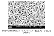
- 2 is a photograph showing an SEM image of a microporous film produced in Example 1.
- FIG. 4 is a photograph showing an SEM image of a microporous film produced in Example 2.
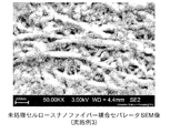
- FIG. 4 is a photograph showing an SEM image of a microporous film produced in Example 3.
- the present invention provides a cellulose powder dispersion mixture obtained by uniformly dispersing a hydroxyl group of cellulose in a powder particle form using a dibasic acid anhydride to a plasticizer to obtain a cellulose powder dispersion mixture. And a method for producing a polyolefin microporous stretched film containing cellulose nanofibers, in which cellulose is uniformly dispersed in a nanofiber form, and a cellulose nanofiber microporous composite film and non- It is to provide a separator for a water secondary battery.
- the raw material cellulose used is hydrophilic as it is and is difficult to disperse in paraffin.
- a suspension in which a hydroxyl group in a cellulose nanofiber molecular structure is esterified or etherified, or a secondary addition treatment of propylene oxide or the like after esterification treatment is dispersed in a plasticizer such as paraffin.
- the microporous sheet can be produced by the same wet method as the conventional apparatus configuration and process.
- the polyolefin resin in the present invention refers to a polyolefin resin used for ordinary extrusion, injection, inflation, blow molding and the like, and includes ethylene, propylene, 1-butene, 4-methyl-1-pentene, 1-hexene, and Homopolymers and copolymers such as 1-octene, multistage polymers and the like can be used.
- polyolefins selected from the group of these homopolymers, copolymers, and multistage polymers can be used alone or in combination.
- the polymer include low density polyethylene, linear low density polyethylene, medium density polyethylene, high density polyethylene, ultrahigh molecular weight polyethylene, isotactic polypropylene, atactic polypropylene, ethylene-propylene random copolymer, polybutene. And ethylene propylene rubber.
- a resin mainly composed of high-density polyethylene from the required performance of high melting point and high strength it is preferable to use a resin mainly composed of high-density polyethylene from the required performance of high melting point and high strength.
- the polyethylene resin preferably accounts for 50% by weight or more of the resin component.
- the amount of the ultra-high-molecular-weight polyolefin having a molecular weight of 1,000,000 or more exceeds 10 parts by weight, it becomes difficult to uniformly knead, and therefore the amount is preferably 10 parts by weight or less.
- CeNF used in the present invention has a fiber diameter of nano-order when dispersed in a polyolefin, and a part of hydroxyl groups present on the fiber surface is polyesterified monoester. Thereby, it is possible to provide a separator that suppresses its own agglomeration, has high uniform dispersibility with polyolefin, is easily kneaded and formed into a sheet, and has mechanical and thermal characteristics superior to conventional separator characteristics.
- CeNF may be subjected to a secondary treatment such as propylene oxide addition (PO addition) in order to further improve dispersibility after monoesterification.
- PO addition propylene oxide addition
- the plasticizer used in the present invention is nonane, decane, decalin, paraxylene, undecane, a linear or cyclic aliphatic hydrocarbon of dodecane, and a mineral oil fraction having a boiling point corresponding to these,
- phthalic acid esters which are liquid at room temperature such as dibutyl phthalate and dioctyl phthalate can be used.
- the CeNF composite porous film of the present invention may be a single layer or a multilayer, and it is sufficient that CeNF is contained in at least one layer constituting the multilayer film.
- the final film thickness is preferably in the range of 5 ⁇ m to 50 ⁇ m. If the film thickness is 5 ⁇ m or more, the mechanical strength is sufficient, and if it is 50 ⁇ m or less, the occupied volume of the separator is reduced, which tends to be advantageous in increasing the battery capacity.
- the air permeability of the porous film of the present invention is preferably in the range of 50 seconds / 100 cc to 1000 seconds / 100 cc. When used as a battery separator, self-discharge is small when the air permeability is 50 seconds / 100 cc or more, and good charge / discharge characteristics are obtained when the air permeability is 1000 seconds / 100 cc or less.
- film thickness and porosity For the film thickness, a sample was cut into a 50 ⁇ 50 mm square, 25 points of each part of the sheet were measured using a micro cage, and the average value was taken as the film thickness. The porosity was calculated from the theoretical weight calculated from the actual weight, density and volume of the sheet. Gurley value: The Gurley value was measured using a Gurley type automatic measuring machine (manufactured by TESTING MACHINES INC).
- Puncture strength The puncture strength was measured using an automated puncture strength meter (manufactured by Kato Tech Co., Ltd .: KES-FB3-AUTO). The produced sheet was cut into a 50 ⁇ 50 mm square, and the puncture strength at each position was calculated at intervals of 5 mm to obtain the average value of each sheet.
- FE-SEM observation The surface of the prepared sheet was deposited using an ion sputtering device (ESC-101 made by Eliox), platinum was deposited at a thickness of about 3 nm, and the surface was made using FE-SEM (SUPRA55VP made by Carl Zeiss) Was observed microscopically.
- ESC-101 made by Eliox
- platinum was deposited at a thickness of about 3 nm
- FE-SEM SUPRA55VP made by Carl Zeiss
- Example 2 In the method of Example 1, cellulose nanofibers to which propylene oxide was added as a secondary treatment after the SA treatment was used. The raw material composition is shown in Example 2 of Table 1. The rest is the same as in the first embodiment.
- Example 3 In the method of Example 1, cellulose not subjected to a known SA treatment was used as a raw material. The raw material composition is shown in Example 3 of Table 1. The rest is the same as in the first embodiment.
- Comparative Example 1 By the method of Example 1, a sheet was produced from a raw material not using cellulose nanofibers.
- the raw material composition is shown in Comparative Example 1 in Table 1 described later. Other than that is the same as in Example 1.
- Comparative Example 2 A sheet was produced using cellulose nanofiber composite polyethylene pellets produced by kneading and dewatering a water slurry obtained by converting the raw material cellulose into SA and performing a starburst treatment by the method of Example 1.
- the raw material composition is shown in Comparative Example 2 in Table 1. Others were the same as in Example 1.
- Comparative Example 3 Using cellulose nanofiber composite polyethylene pellets produced by kneading and dewatering water slurry obtained by converting the raw material cellulose into SA and starburst treatment with 030S, the raw fabric is produced by continuously kneading with TEX30 ⁇ in FIG. did.
- the raw material composition is shown in Comparative Example 3 in Table 1. Subsequent simultaneous biaxial stretching, degreasing and heat setting were the same as in Example 1.
- Comparison of Results FIG. 4 shows the state of dispersion in paraffin before and after the SA conversion, and after 18 minutes of swelling and stirring for 40 minutes, but the well-known SA-converted cellulose is significantly more paraffinized than without treatment. The dispersion of is improved.
- FIGS. 5, 6 and 7 show SEM images of the microporous membranes produced under the conditions of Examples 1 to 3.
- FIG. 7 shows a sample formed by kneading a raw material obtained by mixing untreated cellulose powder with liquid paraffin and ultrahigh molecular weight polyethylene powder as it is, and then forming a film. From this, many lumps which become nodes are seen in the polyethylene crystal fiber. It is considered that cellulose is aggregated in this portion, and it is estimated that the dispersion state in polyethylene is not good.
- FIG. 5 is a sample using cellulose powder that has been converted to SA in advance, but there are fewer clumps as nodes compared to FIG. 7, and it is presumed that the dispersion state has been improved. Further, FIG.
- FIG. 6 shows a result of a sample that has been converted to SA in advance and then subjected to secondary PO addition processing. Compared to FIG. 5, almost no lumps are seen, and it is considered that the cellulose nanofibers are uniformly dispersed in the ultrahigh molecular weight HDPE.
- Table 4 shows the main separator characteristics in Examples 1 to 3 and Comparative Examples 1 to 3. Comparing the results of Examples 1 to 3, the numerical values of the air permeability that affect the battery characteristics of the lithium ion battery are in the order of Example 2 ⁇ Example 1 ⁇ Example 3. A low Gurley value indicates that lithium ions can pass easily. This indicates that the fine pores are well formed in Example 2 because the dispersion of CeNF is good and there is no aggregation compared to the others. The porosity is higher in Example 1, but the microporous distribution is uneven, which is considered to be caused by uneven opening of holes having a large diameter compared to Example 2.
- the puncture strength is important for prevention of film breakage due to foreign matters during winding of the battery and prevention of short circuit due to film breakage caused by lithium ion dendrite caused by deterioration over time.
- the puncture strength is greatly increased as compared with 3, which is considered to be a result of the addition effect of CeNF.
- the heat shrinkage contributes to the safety of the battery.
- the shrinkage of the TD is small, a short circuit between the positive and negative electrodes due to the shrinkage of the sheet due to abnormal heat generation during the battery runaway is prevented.
- Example 2 has a small value, which is considered to be due to the addition effect of CeNF.
- Example 3 When Examples 1 to 3 are compared with a conventional separator that does not combine CeNF, all the values of air permeability, puncture strength, and 120 ° C. heat shrinkage are improved except for Example 3. However, the porosity and air permeability of Example 3 were poorer than those of the sample not composited with CeNF. This is thought to be because the porosity and the air permeability are affected by the fact that the fine pores are not uniformly formed due to the poor dispersion state of CeNF. Comparative Example 2 is a result of filming polyethylene pellets composited with CeNF in advance by the same method. However, when film forming is performed with a kneader under the same conditions as the others, all characteristic values are deteriorated.
- Comparative Example 3 the characteristics of the film in which paraffin is continuously kneaded with TEX30 ⁇ indicate that each characteristic value is good.
- the results generally vary greatly depending on the state of kneading, but it is thought that the micropores are not formed well due to insufficient swelling in the pellet state, particularly affecting the compatibilization with paraffin. . That is, similar to the results of Comparative Examples 2 and 3, the results of Examples 1 and 2 indicate that the sheet formation by continuous kneading is further optimized, and the SANF-treated CeNF is dispersed in paraffin. It is shown that it is possible to provide a separator with improved characteristics that cannot be achieved by the conventional method simply by using one.
- a second step of obtaining a polyolefin resin composition by melt-kneading a third step of extruding the polyolefin resin composition to obtain an extruded product, and stretching the extruded product as shown in FIG.
- the fourth step of obtaining a film by stretching with a machine the fifth step of extracting a plasticizer from the film, and the shrinkage while stretching the film at a temperature below the melting point of the polyolefin raw material after extracting the plasticizer.
- the biaxial kneading extruder as shown in FIG. 3 is used only once through the second and third steps.
- a method for producing a polyolefin microporous stretched film containing cellulose nanofibers, and the lipophilic treatment is characterized in that after a half-esterification treatment, a secondary propylene oxide addition treatment is carried out.
- a method for producing a stretched film and The method for producing a polyolefin microporous stretched film with cellulose nanofibers according to the present invention, wherein the cellulose powder in the cellulose powder dispersion mixture is 0.01 to 30 weight percent, and the cellulose nanofibers according to the present invention is contained.
- a polyolefin microporous composite film is a cellulose nanofiber microporous composite film comprising the cellulose nanofiber-containing polyolefin microporous stretched film produced by the above production method, and produced by the above production method.
- Nonaqueous secondary battery separator according to Ming a nonaqueous secondary battery separator characterized by comprising the cellulose nanofibers containing polyolefin microporous stretched film prepared in the manufacturing process.
- the method for producing a polyolefin microporous stretched film containing cellulose nanofibers, the cellulose nanofiber microporous composite film, and the separator for non-aqueous secondary battery according to the present invention can contribute to the realization of a film product with improved puncture strength.
Landscapes
- Chemical & Material Sciences (AREA)
- Chemical Kinetics & Catalysis (AREA)
- General Chemical & Material Sciences (AREA)
- Electrochemistry (AREA)
- Engineering & Computer Science (AREA)
- Manufacturing & Machinery (AREA)
- Health & Medical Sciences (AREA)
- Medicinal Chemistry (AREA)
- Polymers & Plastics (AREA)
- Organic Chemistry (AREA)
- Materials Engineering (AREA)
- Mechanical Engineering (AREA)
- Cell Separators (AREA)
- Manufacture Of Porous Articles, And Recovery And Treatment Of Waste Products (AREA)
- Compositions Of Macromolecular Compounds (AREA)
Abstract
Description
従来、セルロースナノファイバー(CeNF)は水酸基を擁するため親水性であり、ポリオレフィンなどの母材に混ぜて複合化する場合、CeNF同士が水素結合により凝集し塊となり母材中で均一に分散することができなかった。例えばCeNFを複合化したフィルムを製造する場合、まず親水性のセルロースナノファイバーを水中に分散させた水スラリーを、押出機で混練中のポリオレフィンに注入混合し、その後脱水することでCeNF複合ポリオレフィン材料を製造し、これを原料としてフィルムを製造していた。または、CeNF自体を主成分とした不織布として使用していた。
また、微多孔化したポリオレフィンシートは、非水系二次電池のセパレータとしての使用が考えられ、セパレータの製造方法としては、一般的に湿式法により前記CeNF複合ポリオレフィン原料とパラフィンなどの可塑剤を両者の融点以上の温度下で混練してTダイから押出成形し冷却した後、相分離した可塑剤を塩化メチレンなどの抽出剤で除去して微多孔を開孔したフィルムを製造していた。
この発明は従来のものの課題を解決するためになされたもので、リチウムイオン電池用セパレータとして要求される機械的、熱的特性のうち、特に突刺し強度とショート温度を改善したCeNF複合ポリオレフィンセパレータを高品質にかつ従来法と比べて安価に提供することを目的としている。
また、本発明は粉末粒径のセルロースの水酸基を二塩基酸無水物を用いて親油性処理したものを、可塑剤に均一分散させて得たセルロース粉末分散混合物を得、それを用いてポリオレフィンと混練・解繊し、高分散状態で複合化することで、一般的な湿式法の装置構成およびプロセスを変えることなく、かつ、工程中で二軸押出機は一度だけの使用として、非水系二次電池用微多孔シート等のセルロースナノファイバー入りポリオレフィン微多孔延伸フィルムを製造可能とする。
また、本発明による非水二次電池用セパレータは、前記の何れかの製造方法で製造した前記セルロースナノファイバー入りポリオレフィン微多孔延伸フィルムからなる構成である。
すなわち、粉末粒形のセルロースの水酸基を二塩基酸無水物を用いて親油性処理したものを、可塑剤に均一分散させてセルロース粉末分散混合物を得る第1工程と、前記セルロース粉末分散混合物とポリオレフィンとを溶融混練してポリオレフィン樹脂組成物を得る第2工程と、前記ポリオレフィン樹脂組成物を押出成形して押出成形体を得る第3工程と、前記押出成形体を図2に示すようなフィルム延伸機で延伸してフィルムを得る第4工程と、前記フィルムから可塑剤を抽出する第5工程と、前記可塑剤を抽出後に前記ポリオレフィン原料の融点以下の温度で前記シートフィルムを延伸しつつ収縮性を抑えるための熱固定を行う第6工程とからなり、図3に示すような二軸混練押出機は前記第2、第3工程を通して一度だけの使用であることにより、親油性処理化などの修飾処理を施したセルロース粉末を可塑剤であるパラフィン中に分散させた混合物を用いて、従来の湿式法と同じ方法でポリオレフィンに添加して、ポリオレフィンと可塑剤を相溶化し、同時にCeNFをポリオレフィン中に分散・複合化する事で、従来のセパレータと比較し2軸混練機を1度使用するだけでよいため、複合セパレータ中へのセルロースの収率も制御しやすく、またポリオレフィン中での均一分散が可能となる。このことにより、コストダウンとなる。また得られた材料の機械強度および熱特性が改善され、安全性が向上した製品とすることが可能となる。
また、所定の粉末粒形のセルロースの水酸基を二塩基酸無水物を用いて半エステル化処理したものを、流動パラフィンからなる前記ポリオレフィンの前記セルロース粉末分散可塑剤に均一分散させたことを特徴とするセルロースナノファイバー入りポリオレフィン微多孔延伸フィルムの製造方法により、従来の装置構成を変えずに複合化が可能になる効果が得られる。
また、前記親油性処理として半エステル化処理を行った後、二次的にプロピレンオキシド付加処理を行ったことを特徴とするセルロースナノファイバー入りポリオレフィン微多孔延伸フィルムの製造方法により、大きな分子であるプロピレンオキシドが付加され、立体的障害効果とより高い親油性の付与により、さらなる高分散、凝集抑制の効果が得られる。
また、前記可塑剤として流動パラフィン、ノナン、デカン、デカリン、パラキシレン、ウンデカン、ドデカンの鎖状又は環式の脂肪族炭化水素、及び沸点がこれらに対応する鉱油留分、並びにジブチルフタレート、ジオクチルフタレートの室温では液状のフタル酸エステルのうち一種類又は数種類の混合物を用いることを特徴とするセルロースナノファイバー入りポリオレフィン微多孔延伸フィルムの製造方法により、原料ポリオレフィンに対する適切な組合せを選定できる効果が得られる。
また、前記セルロース粉末分散混合物中のセルロース粉末が0.01~30重量パーセントであることを特徴とするセルロースナノファイバー入りポリオレフィン微多孔延伸フィルムの製造方法により、要求に応じた特性の付与が可能となる効果が得られる。
また、前記の何れかの製造方法で製造した前記セルロースナノファイバー入りポリオレフィン微多孔延伸フィルムからなることを特徴とするセルロースナノファイバーポリオレフィン微多孔複合フィルムにより、シートの耐熱性、強度向上の効果が得られる。
また、前記の何れかの製造方法で製造した前記ポリオレフィン微多孔延伸フィルム中のセルロース粉末が前記ポリオレフィン微多孔延伸フィルム全重量に対して0.01~30重量パーセントであることを特徴とするセルロースナノファイバー微多孔複合フィルムにより、目的に適した配合による、最適な特性が付与できる効果が得られる。
また、前記の何れかの製造方法で製造した前記セルロースナノファイバー入りポリオレフィン微多孔延伸フィルムからなることを特徴とする非水二次電池用セパレータにより、セパレータの安全性向上の効果が得られる。
本発明はCeNF複合化セパレータを製造するために、一般的な湿式法で用いられるパラフィンなどの可塑剤へCeNFを高度に均一分散させることで、従来の装置構成は変えずに、二軸混練押出機を一度だけ用いることにより、高強度・高耐熱なセルロースナノファイバー微多孔複合フィルムによる非水系二次電池用セパレータの供給を可能としたものである。
また、本発明に用いる可塑剤は流動パラフィンなどの他にノナン、デカン、デカリン、パラキシレン、ウンデカン、ドデカンの鎖状又は環式の脂肪族炭化水素、及び沸点がこれらに対応する鉱油留分、並びにジブチルフタレート、ジオクチルフタレート等の室温では液状のフタル酸エステルなどが挙げられる。
膜厚と空孔率:膜厚はサンプルを50×50mm角に切出し、マイクロケージを用いてシートの各部25点を計測し、平均値を膜厚とした。空孔率はシートの実測重量と密度と体積から算出した理論重量より算出した。
ガーレ値:ガーレ値の測定には、ガーレ式自動計測機(TESTING MACHINES INC 社製)を用いて測定した。本測定は、JISP8177に規定されている通り、100ccの空気がシートを通過するまでに要する時間をガーレ値とした。
突刺し強度:突刺し強度の測定には、自動化突刺し強度計(カトーテック社製:KES-FB3-AUTO)を用いて計測を行った。作製したシートを50×50mm角に切出し、5mm間隔で各位置の突刺強度を算出して各シートの平均値を求めた。
FE-SEM観察:作製したシートはイオンスパッタ装置(エリオクス社製ESC-101)を使用し、約3nmの厚さでプラチナ蒸着を行い、FE-SEM(カールツァイス社製SUPRA55VP)を使用して表面をミクロ観察した。
セルロース粉末試料としてセオラスFD-101(旭化成ケミカルズ(株)製)を用いてセルロース:無水コハク酸(SA)=100:11.81の重量比で加圧ニーダにて125℃、20分間混練による半エステル化反応を行い、その後アセトン抽出により未反応物を除去した(周知のSA化処理)。その後、そのSA化処理セルロース微粉末をパラフィン中に混合して24時間膨潤と撹拌処理を行った。原料の組成を表1の実施例1に示した。これを図1のニーダで上記パラフィン70重量部に対し三井ハイゼックス(030S)30重量部を混合して混練後、図2のテンターで同時二軸延伸を行った。混練条件および延伸条件は表2、表3に示した。テンターで二軸延伸を行った後に、塩化メチレンにて流動パラフィンを脱脂し、118℃で10分間ヒートセットを行った。


実施例1の方法で、SA化処理後に二次処理としてプロピレンオキシドを付加したセルロースナノファイバーを用いた。原料組成は表1の実施例2に示した。それ以外は、実施例1と同様である。
(実施例3)
実施例1の方法で、原料として周知のSA化処理を行わないセルロースを用いた。原料組成を表1の実施例3に示した。それ以外は、実施例1と同様である。
実施例1の方法で、セルロースナノファイバーを用いない原料でシートを製作した。原料組成は後述の表1の比較例1に示した。それ以外は実施例1同様である。
(比較例2)
実施例1の方法で、原料セルロースをSA化してスターバースト処理を施した水スラリーを030Sと混練・脱水して製造したセルロースナノファイバー複合ポリエチレンペレットを使用してシートを製造した。原料組成は表1の比較例2に示した。その他は実施例1と同様とした。
(比較例3)
原料セルロースをSA化してスターバースト処理を施した水スラリーを030Sと混練・脱水して製造したセルロースナノファイバー複合ポリエチレンペレットを使用して、図3のTEX30αで連続的に混練して原反を製造した。原料組成は表1の比較例3に示した。その後の同時二軸延伸と脱脂およびヒートセットは実施例1と同様とした。
結果比較
前記SA化前後、18時間膨潤および撹拌処理後40分経過時のパラフィン中への分散状況を図4に示したが、処理無しに比べて周知のSA化したセルロースは格段にパラフィン中への分散が向上している。
突刺強度は電池の巻捲時に異物による破膜防止、経時的劣化で生じるリチウムイオンデンドライトによる破膜での短絡防止などに重要である。実施例1、2は3と比較して突刺強度が大きく増加しており、CeNFの添加効果での結果と考えられる。
熱収縮性は電池の安全に寄与するものであるが、特にTDの収縮性が小さければ電池の暴走時の異常発熱によるシートの収縮による正負極間での短絡を防止する。実施例1~3のTDで比較すると、実施例3よりも実施例1、2に改善効果が見られる。特に、実施例2が小さな値となっており、CeNFの添加効果によるものと考えられる。

比較例2は事前にCeNFを複合化したポリエチレンペレットを同様な方法でフィルム化した結果であるが、ニーダでフィルム成形を他と同条件で行うと、全ての特性値で悪くなる。一方、比較例3で示したように、パラフィンを連続的にTEX30αで混練したフィルムの特性は各特性値が良好な結果を示している。湿式セパレータ製造プロセスでは一般的に混練時の状態で結果が大きく違ってくるが、特にパラフィンとの相溶化に影響する膨潤がペレット状態では不足することで、上手く微多孔が形成されないためと考えられる。つまり、比較例2と3の結果と同様に、実施例1、2の結果は、連続的混練によるシート形成でさらに最適化されることを示しており、SA化処理したCeNFをパラフィンに分散させたものを用いるだけで従来法では到達できない特性が改善されたセパレータが提供可能であることを示している。
すなわち、粉末粒形のセルロースの水酸基を二塩基酸無水物を用いて親油性処理したものを、可塑剤に均一分散させてセルロース粉末分散混合物を得る第1工程と、前記セルロース粉末分散混合物とポリオレフィンとを溶融混練してポリオレフィン樹脂組成物を得る第2工程と、前記ポリオレフィン樹脂組成物を押出成形して押出成形体を得る第3工程と、前記押出成形体を図2に示すようなフィルム延伸機で延伸してフィルムを得る第4工程と、前記フィルムから可塑剤を抽出する第5工程と、前記可塑剤を抽出後に前記ポリオレフィン原料の融点以下の温度で前記フィルムを延伸しつつ収縮性を抑えるための熱固定を行う第6工程とからなり、図3に示すような二軸混練押出機は前記第2、第3工程を通して一度だけの使用であることを特徴とするセルロースナノファイバー入りポリオレフィン微多孔延伸フィルムの製造方法であり、また、前記親油性処理は、半エステル化処理を行った後、二次的にプロピレンオキシド付加処理を行うことを特徴とする前記のセルロースナノファイバー入りポリオレフィン微多孔延伸フィルムの製造方法であり、また、前記可塑剤として、流動パラフィン、ノナン、デカン、デカリン、パラキシレン、ウンデカン、ドデカンの鎖状又は環式の脂肪族炭化水素、及び沸点がこれらに対応する鉱油留分、並びにジブチルフタレート、ジオクチルフタレートの室温では液状のフタル酸エステルのうち一種類又は数種類の混合物を用いることを特徴とする前記のセルロースナノファイバー入りポリオレフィン微多孔延伸フィルムの製造方法であり、また、前記セルロース粉末分散混合物中のセルロース粉末が0.01~30重量パーセントであることを特徴とする前記のセルロースナノファイバー入りポリオレフィン微多孔延伸フィルムの製造方法であり、また、本発明によるセルロースナノファイバー入りポリオレフィン微多孔複合フィルムは、前記の製造方法で製造した前記セルロースナノファイバー入りポリオレフィン微多孔延伸フィルムからなることを特徴とするセルロースナノファイバー微多孔複合フィルムであり、また、前記の製造方法で製造した前記ポリオレフィン微多孔延伸フィルム中のセルロース粉末が前記ポリオレフィン微多孔延伸フィルム全重量に対して0.01~30重量パーセントであることを特徴とするセルロースナノファイバー微多孔複合フィルムであり、本発明による非水二次電池用セパレータは、前記の製造方法で製造した前記セルロースナノファイバー入りポリオレフィン微多孔延伸フィルムからなることを特徴とする非水二次電池用セパレータである。
本出願は、2013年6月4日出願の日本国特許出願(特願2013-117630)に基づくものであり、その内容はここに参照として取り込まれる。
Claims (7)
- 粉末粒径のセルロースの水酸基を二塩基酸無水物を用いて親油性処理したものを、可塑剤に均一分散させてセルロース粉末分散混合物を得る第1工程と、前記セルロース粉末分散混合物とポリオレフィンとを溶融混練してポリオレフィン樹脂組成物を得る第2工程と、前記ポリオレフィン樹脂組成物を押出成形して押出成形体を得る第3工程と、前記押出成形体をフィルム延伸機で延伸してフィルムを得る第4工程と、前記フィルムから可塑剤を抽出する第5工程と、前記可塑剤を抽出後に前記ポリオレフィン原料の融点以下の温度で前記フィルムを延伸しつつ収縮性を抑えるための熱固定を行う第6工程と、とからなり、二軸混練押出機は前記第2、第3工程を通して一度だけの使用であることを特徴とするセルロースナノファイバー入りポリオレフィン微多孔延伸フィルムの製造方法。
- 前記親油性処理は、半エステル化処理を行った後、二次的にプロピレンオキシド付加処理を行うことを特徴とする請求項1記載のセルロースナノファイバー入りポリオレフィン微多孔延伸フィルムの製造方法。
- 前記可塑剤として、流動パラフィン、ノナン、デカン、デカリン、パラキシレン、ウンデカン、ドデカンの鎖状又は環式の脂肪族炭化水素、及び沸点がこれらに対応する鉱油留分、並びにジブチルフタレート、ジオクチルフタレートの室温では液状のフタル酸エステルのうち一種類又は数種類の混合物を用いることを特徴とする請求項1または2記載のセルロースナノファイバー入りポリオレフィン微多孔延伸フィルムの製造方法。
- 前記セルロース粉末分散混合物中のセルロース粉末が0.01~30重量パーセントであることを特徴とする請求項1ないし3の何れかに記載のセルロースナノファイバー入りポリオレフィン微多孔延伸フィルムの製造方法。
- 請求項1から4の何れかの製造方法で製造した前記セルロースナノファイバー入りポリオレフィン微多孔延伸フィルムからなることを特徴とするセルロースナノファイバー微多孔複合フィルム。
- 請求項1から4の何れかの製造方法で製造した前記ポリオレフィン微多孔延伸フィルム中のセルロース粉末が前記ポリオレフィン微多孔延伸フィルム全重量に対して0.01~30重量パーセントであることを特徴とするセルロースナノファイバー微多孔複合フィルム。
- 請求項1から4の何れかの製造方法で製造した前記セルロースナノファイバー入りポリオレフィン微多孔延伸フィルムからなることを特徴とする非水二次電池用セパレータ。
Priority Applications (4)
| Application Number | Priority Date | Filing Date | Title |
|---|---|---|---|
| EP14808085.6A EP3006492B1 (en) | 2013-06-04 | 2014-06-04 | Process for producing cellulose-nanofiber-filled microporous stretched polyolefin film, microporous cellulose-nanofiber composite film, and separator for non-aqueous secondary battery |
| US14/895,856 US10840491B2 (en) | 2013-06-04 | 2014-06-04 | Process for producing cellulose-nanofiber-filled microporous stretched polyolefin film, microporous cellulose-nanofiber composite film, and separator for non-aqueous secondary battery |
| KR1020157034580A KR101845145B1 (ko) | 2013-06-04 | 2014-06-04 | 셀룰로오스 나노섬유를 함유하는 폴리올레핀 미세 다공성 연신 필름의 제조 방법 및 셀룰로오스 나노섬유 미세 다공성 복합 필름 및 비수 이차 전지용 세퍼레이터 |
| CN201480032245.0A CN105263998B (zh) | 2013-06-04 | 2014-06-04 | 含有纤维素纳米纤维的聚烯烃多微孔拉伸膜的制造方法、纤维素纳米纤维多微孔复合膜及非水二次电池用隔膜 |
Applications Claiming Priority (2)
| Application Number | Priority Date | Filing Date | Title |
|---|---|---|---|
| JP2013-117630 | 2013-06-04 | ||
| JP2013117630A JP5984307B2 (ja) | 2013-06-04 | 2013-06-04 | セルロースナノファイバー入りポリオレフィン微多孔延伸フィルムの製造方法 |
Publications (1)
| Publication Number | Publication Date |
|---|---|
| WO2014196551A1 true WO2014196551A1 (ja) | 2014-12-11 |
Family
ID=52008187
Family Applications (1)
| Application Number | Title | Priority Date | Filing Date |
|---|---|---|---|
| PCT/JP2014/064802 Ceased WO2014196551A1 (ja) | 2013-06-04 | 2014-06-04 | セルロースナノファイバー入りポリオレフィン微多孔延伸フィルムの製造方法及びセルロースナノファイバー微多孔複合フィルム及び非水二次電池用セパレータ |
Country Status (6)
| Country | Link |
|---|---|
| US (1) | US10840491B2 (ja) |
| EP (1) | EP3006492B1 (ja) |
| JP (1) | JP5984307B2 (ja) |
| KR (1) | KR101845145B1 (ja) |
| CN (1) | CN105263998B (ja) |
| WO (1) | WO2014196551A1 (ja) |
Cited By (8)
| Publication number | Priority date | Publication date | Assignee | Title |
|---|---|---|---|---|
| CN107428977A (zh) * | 2015-02-26 | 2017-12-01 | 株式会社日本制钢所 | 微多孔膜的制造方法和微多孔膜 |
| WO2019045076A1 (ja) * | 2017-09-04 | 2019-03-07 | 株式会社日本製鋼所 | セルロースナノファイバー分散液、セルロースナノファイバー複合樹脂、及びそれらの製造方法 |
| WO2019064538A1 (ja) * | 2017-09-29 | 2019-04-04 | Attaccato合同会社 | リチウムイオン電池用バインダおよびこれを用いた電極並びにセパレータ |
| US10494448B2 (en) * | 2015-09-30 | 2019-12-03 | The Japan Steel Works, Ltd. | Apparatus for continuously producing chemically-modified cellulose and method used in same |
| WO2020017247A1 (ja) * | 2018-07-18 | 2020-01-23 | 理研化学工業株式会社 | 樹脂成形品およびその製造方法 |
| WO2020090014A1 (ja) * | 2018-10-30 | 2020-05-07 | Attaccato合同会社 | 非水電解質二次電池および非水電解質二次電池の製造方法 |
| WO2020090313A1 (ja) * | 2018-10-30 | 2020-05-07 | 株式会社日本製鋼所 | 多孔質フィルムの製造方法および多孔質フィルム |
| WO2020196800A1 (ja) * | 2019-03-27 | 2020-10-01 | 古河電気工業株式会社 | 有機繊維強化樹脂成形体及びその製造方法 |
Families Citing this family (12)
| Publication number | Priority date | Publication date | Assignee | Title |
|---|---|---|---|---|
| JP6103602B2 (ja) * | 2014-11-05 | 2017-03-29 | 株式会社日本製鋼所 | キチンナノファイバー分散可塑剤及びキチンナノファイバー入りポリオレフィン微多孔延伸フィルムの製造方法 |
| JP6547414B2 (ja) * | 2015-05-20 | 2019-07-24 | 星光Pmc株式会社 | 変性セルロース繊維含有樹脂組成物、成形材料および成形体 |
| JP6821475B2 (ja) * | 2016-03-15 | 2021-01-27 | 株式会社服部商店 | 修飾セルロースナノファイバーの製造方法 |
| US10030093B2 (en) | 2016-03-29 | 2018-07-24 | Toyota Shatai Kabushiki Kaisha | Cellulose nanofiber powder and method for producing the same |
| JP6764718B2 (ja) | 2016-07-25 | 2020-10-07 | トヨタ車体株式会社 | 成形材料混合物及びその製造方法 |
| KR102070374B1 (ko) * | 2016-12-28 | 2020-01-29 | 아사히 가세이 가부시키가이샤 | 셀룰로오스 함유 수지 조성물 및 셀룰로오스 제제 |
| JP6479904B2 (ja) * | 2016-12-28 | 2019-03-06 | 旭化成株式会社 | セルロース製剤 |
| TWI755429B (zh) * | 2017-09-29 | 2022-02-21 | 日商Attaccato合同公司 | 鋰離子電池用黏合劑及使用其之電極暨分隔件 |
| TWI804131B (zh) * | 2017-09-29 | 2023-06-01 | 日商Attaccato合同公司 | 於n-甲基-2-吡咯啶酮中分散有纖維素奈米纖維的液體之製造方法 |
| JP6944861B2 (ja) * | 2017-11-30 | 2021-10-06 | 株式会社日本製鋼所 | セルロース含有多孔質樹脂成形体の製造方法 |
| CN109742294B (zh) * | 2018-12-25 | 2022-03-04 | 江西省通瑞新能源科技发展有限公司 | 一种纤维素隔膜的制备方法 |
| CN120073221B (zh) * | 2025-03-11 | 2025-11-21 | 扬州纳力新材料科技有限公司 | 一种提升电池抗冲击性能的隔膜制备方法 |
Citations (4)
| Publication number | Priority date | Publication date | Assignee | Title |
|---|---|---|---|---|
| JP2003123724A (ja) * | 2001-10-11 | 2003-04-25 | Toyota Central Res & Dev Lab Inc | リチウム二次電池用セパレータおよびそれを用いたリチウム二次電池 |
| JP2009293167A (ja) | 2008-06-09 | 2009-12-17 | Nobuo Shiraishi | ナノ繊維の製造方法、ナノ繊維、混合ナノ繊維、複合化方法、複合材料および成形品 |
| JP2012167202A (ja) * | 2011-02-15 | 2012-09-06 | Olympus Corp | 複合樹脂組成物及び成形体 |
| JP2013056958A (ja) | 2011-09-07 | 2013-03-28 | Japan Steel Works Ltd:The | セルロースナノファイバー入りポリオレフィン微多孔延伸フィルムの製造方法及びセルロースナノファイバー入りポリオレフィン微多孔延伸フィルム及び非水二次電池用セパレータ |
Family Cites Families (9)
| Publication number | Priority date | Publication date | Assignee | Title |
|---|---|---|---|---|
| US3804884A (en) * | 1972-12-07 | 1974-04-16 | Dow Chemical Co | Esterification process and catalyst therefor |
| DE19714059A1 (de) * | 1997-04-05 | 1998-10-08 | Wolff Walsrode Ag | Thermoplastischer Werkstoff auf der Basis von Polysacchariden sowie ein Verfahren zu dessen Herstellung und Verwendung desselben |
| WO2005061599A1 (ja) | 2003-12-24 | 2005-07-07 | Asahi Kasei Chemicals Corporation | ポリオレフィン製微多孔膜 |
| JP5319947B2 (ja) * | 2008-03-25 | 2013-10-16 | 株式会社東芝 | 非水電解質電池 |
| EP2551293A4 (en) | 2010-03-24 | 2016-08-03 | Teijin Ltd | MICROPOROUS POLYOLEFINMEMBRANE, PRODUCTION PROCESS THEREFOR, SEPARATOR FOR A NON-WATER SECONDARY BATTERY AND NON-WATER SECONDARY BATTERY |
| FI122776B (fi) * | 2010-11-30 | 2012-06-29 | Upm Kymmene Corp | Menetelmä ja järjestelmä nanoselluloosan valmistamiseksi sekä nanoselluloosa |
| US9666848B2 (en) | 2011-05-20 | 2017-05-30 | Dreamweaver International, Inc. | Single-layer lithium ion battery separator |
| CA2824635A1 (en) * | 2011-10-13 | 2013-04-18 | Tokushu Tokai Paper Co., Ltd. | Separator for electrochemical device and process for preparing the same |
| US20150171395A1 (en) * | 2012-07-27 | 2015-06-18 | Dic Corporation | Modified-cellulose-nanofiber containing polyethylene fine porous film, separator, and lithium-ion battery including the same |
-
2013
- 2013-06-04 JP JP2013117630A patent/JP5984307B2/ja active Active
-
2014
- 2014-06-04 EP EP14808085.6A patent/EP3006492B1/en not_active Not-in-force
- 2014-06-04 US US14/895,856 patent/US10840491B2/en active Active
- 2014-06-04 KR KR1020157034580A patent/KR101845145B1/ko active Active
- 2014-06-04 WO PCT/JP2014/064802 patent/WO2014196551A1/ja not_active Ceased
- 2014-06-04 CN CN201480032245.0A patent/CN105263998B/zh active Active
Patent Citations (4)
| Publication number | Priority date | Publication date | Assignee | Title |
|---|---|---|---|---|
| JP2003123724A (ja) * | 2001-10-11 | 2003-04-25 | Toyota Central Res & Dev Lab Inc | リチウム二次電池用セパレータおよびそれを用いたリチウム二次電池 |
| JP2009293167A (ja) | 2008-06-09 | 2009-12-17 | Nobuo Shiraishi | ナノ繊維の製造方法、ナノ繊維、混合ナノ繊維、複合化方法、複合材料および成形品 |
| JP2012167202A (ja) * | 2011-02-15 | 2012-09-06 | Olympus Corp | 複合樹脂組成物及び成形体 |
| JP2013056958A (ja) | 2011-09-07 | 2013-03-28 | Japan Steel Works Ltd:The | セルロースナノファイバー入りポリオレフィン微多孔延伸フィルムの製造方法及びセルロースナノファイバー入りポリオレフィン微多孔延伸フィルム及び非水二次電池用セパレータ |
Non-Patent Citations (1)
| Title |
|---|
| See also references of EP3006492A4 |
Cited By (19)
| Publication number | Priority date | Publication date | Assignee | Title |
|---|---|---|---|---|
| US10633498B2 (en) | 2015-02-26 | 2020-04-28 | The Japan Steel Works, Ltd. | Method for manufacturing microporous film and microporous film |
| EP3263636A4 (en) * | 2015-02-26 | 2018-08-01 | The Japan Steel Works, Ltd. | Method for manufacturing microporous film and microporous film |
| CN107428977B (zh) * | 2015-02-26 | 2020-07-28 | 株式会社日本制钢所 | 微多孔膜的制造方法和微多孔膜 |
| CN107428977A (zh) * | 2015-02-26 | 2017-12-01 | 株式会社日本制钢所 | 微多孔膜的制造方法和微多孔膜 |
| US10494448B2 (en) * | 2015-09-30 | 2019-12-03 | The Japan Steel Works, Ltd. | Apparatus for continuously producing chemically-modified cellulose and method used in same |
| WO2019045076A1 (ja) * | 2017-09-04 | 2019-03-07 | 株式会社日本製鋼所 | セルロースナノファイバー分散液、セルロースナノファイバー複合樹脂、及びそれらの製造方法 |
| JP2019044087A (ja) * | 2017-09-04 | 2019-03-22 | 株式会社日本製鋼所 | セルロースナノファイバー分散液、及び、セルロースナノファイバー複合樹脂 |
| EP3691002A4 (en) * | 2017-09-29 | 2021-06-30 | Attaccato Limited Liability Company | BINDING AGENT FOR LITHIUM-ION BATTERIES AND ELECTRODE AND SEPARATOR WITH IT |
| WO2019064538A1 (ja) * | 2017-09-29 | 2019-04-04 | Attaccato合同会社 | リチウムイオン電池用バインダおよびこれを用いた電極並びにセパレータ |
| JPWO2019064538A1 (ja) * | 2017-09-29 | 2020-09-10 | Attaccato合同会社 | リチウムイオン電池用バインダおよびこれを用いた電極並びにセパレータ |
| WO2020017247A1 (ja) * | 2018-07-18 | 2020-01-23 | 理研化学工業株式会社 | 樹脂成形品およびその製造方法 |
| JPWO2020017247A1 (ja) * | 2018-07-18 | 2020-10-01 | 理研化学工業株式会社 | 樹脂成形品およびその製造方法 |
| JP2020183508A (ja) * | 2018-07-18 | 2020-11-12 | 理研化学工業株式会社 | 樹脂成形品およびその製造方法 |
| WO2020090014A1 (ja) * | 2018-10-30 | 2020-05-07 | Attaccato合同会社 | 非水電解質二次電池および非水電解質二次電池の製造方法 |
| WO2020090313A1 (ja) * | 2018-10-30 | 2020-05-07 | 株式会社日本製鋼所 | 多孔質フィルムの製造方法および多孔質フィルム |
| JPWO2020196800A1 (ja) * | 2019-03-27 | 2020-10-01 | ||
| WO2020196800A1 (ja) * | 2019-03-27 | 2020-10-01 | 古河電気工業株式会社 | 有機繊維強化樹脂成形体及びその製造方法 |
| JP7502268B2 (ja) | 2019-03-27 | 2024-06-18 | 古河電気工業株式会社 | 有機繊維強化樹脂成形体及びその製造方法 |
| US12325780B2 (en) | 2019-03-27 | 2025-06-10 | Furukawa Electric Co., Ltd. | Organic fiber-reinforced resin formed body and method for producing the same |
Also Published As
| Publication number | Publication date |
|---|---|
| EP3006492A4 (en) | 2017-01-25 |
| JP2014234472A (ja) | 2014-12-15 |
| CN105263998A (zh) | 2016-01-20 |
| EP3006492A1 (en) | 2016-04-13 |
| KR20160007555A (ko) | 2016-01-20 |
| JP5984307B2 (ja) | 2016-09-06 |
| US20160133902A1 (en) | 2016-05-12 |
| CN105263998B (zh) | 2018-09-04 |
| EP3006492B1 (en) | 2018-09-19 |
| KR101845145B1 (ko) | 2018-04-03 |
| US10840491B2 (en) | 2020-11-17 |
Similar Documents
| Publication | Publication Date | Title |
|---|---|---|
| JP5984307B2 (ja) | セルロースナノファイバー入りポリオレフィン微多孔延伸フィルムの製造方法 | |
| JP5052135B2 (ja) | ポリオレフィン微多孔膜及び蓄電池用セパレータ | |
| JP5462227B2 (ja) | セルロースナノファイバー入りポリオレフィン微多孔延伸フィルムの製造方法及びセルロースナノファイバー入りポリオレフィン微多孔延伸フィルム及び非水二次電池用セパレータ | |
| JP5717302B2 (ja) | 積層微多孔膜及び非水電解質二次電池用セパレータ | |
| JP2009185093A (ja) | ポリオレフィン微多孔膜 | |
| JP5128488B2 (ja) | 溶融破断特性に優れるポリオレフィン微多孔膜及びその製造方法 | |
| KR20090094473A (ko) | 다층 다공막 및 그의 제조 방법 | |
| WO2019065073A1 (ja) | ポリオレフィン製微多孔膜、電池用セパレータおよび二次電池 | |
| JP5235487B2 (ja) | 無機粒子含有微多孔膜の製造方法 | |
| JP4220329B2 (ja) | ポリオレフィン微多孔膜及びその製造方法 | |
| JP2009242779A (ja) | ポリオレフィン微多孔膜及び蓄電池用セパレータ | |
| JP6988880B2 (ja) | ポリオレフィン微多孔膜 | |
| JP5592745B2 (ja) | ポリオレフィン製微多孔膜 | |
| JPWO2016104791A1 (ja) | ポリオレフィン樹脂組成物およびポリオレフィン微多孔膜の製造方法 | |
| JP6122941B2 (ja) | セルロースナノファイバー入りポリオレフィン微多孔延伸フィルムの製造に用いるための押出成形体の製造方法 | |
| KR101674985B1 (ko) | 분리막 조성물, 상기 조성물로 형성된 분리막 및 이를 이용한 전지 | |
| JP2015136809A (ja) | ポリオレフィン微多孔膜の製造方法、電池用セパレータ、及び非水電解液二次電池 | |
| JP6103602B2 (ja) | キチンナノファイバー分散可塑剤及びキチンナノファイバー入りポリオレフィン微多孔延伸フィルムの製造方法 | |
| JP6598911B2 (ja) | ポリオレフィン微多孔膜の製造方法、電池用セパレータ、及び非水電解液二次電池 | |
| JP6347801B2 (ja) | ポリオレフィン微多孔膜の製造方法、電池用セパレータ、及び非水電解液二次電池 | |
| DE102023001233A1 (de) | Separator für eine Sekundärbatterie mit nichtwässrigem Elektrolyt | |
| JP2011102368A (ja) | ポリオレフィン微多孔膜、蓄電デバイス用セパレータ及び蓄電デバイス | |
| JP7567443B2 (ja) | ポリオレフィン微多孔膜、及び二次電池 | |
| JP2024109529A (ja) | ポリオレフィン微多孔膜、電池用セパレータ、液体用フィルター |
Legal Events
| Date | Code | Title | Description |
|---|---|---|---|
| WWE | Wipo information: entry into national phase |
Ref document number: 201480032245.0 Country of ref document: CN |
|
| 121 | Ep: the epo has been informed by wipo that ep was designated in this application |
Ref document number: 14808085 Country of ref document: EP Kind code of ref document: A1 |
|
| WWE | Wipo information: entry into national phase |
Ref document number: P1613/2015 Country of ref document: AE |
|
| WWE | Wipo information: entry into national phase |
Ref document number: 2014808085 Country of ref document: EP |
|
| WWE | Wipo information: entry into national phase |
Ref document number: 14895856 Country of ref document: US |
|
| ENP | Entry into the national phase |
Ref document number: 20157034580 Country of ref document: KR Kind code of ref document: A |
|
| NENP | Non-entry into the national phase |
Ref country code: DE |