WO2014199597A1 - 誘導加熱装置 - Google Patents
誘導加熱装置 Download PDFInfo
- Publication number
- WO2014199597A1 WO2014199597A1 PCT/JP2014/002981 JP2014002981W WO2014199597A1 WO 2014199597 A1 WO2014199597 A1 WO 2014199597A1 JP 2014002981 W JP2014002981 W JP 2014002981W WO 2014199597 A1 WO2014199597 A1 WO 2014199597A1
- Authority
- WO
- WIPO (PCT)
- Prior art keywords
- cooking
- cooking container
- icon
- heating
- container
- Prior art date
- Legal status (The legal status is an assumption and is not a legal conclusion. Google has not performed a legal analysis and makes no representation as to the accuracy of the status listed.)
- Ceased
Links
Images


Classifications
-
- H—ELECTRICITY
- H05—ELECTRIC TECHNIQUES NOT OTHERWISE PROVIDED FOR
- H05B—ELECTRIC HEATING; ELECTRIC LIGHT SOURCES NOT OTHERWISE PROVIDED FOR; CIRCUIT ARRANGEMENTS FOR ELECTRIC LIGHT SOURCES, IN GENERAL
- H05B6/00—Heating by electric, magnetic or electromagnetic fields
- H05B6/02—Induction heating
- H05B6/10—Induction heating apparatus, other than furnaces, for specific applications
- H05B6/12—Cooking devices
- H05B6/1209—Cooking devices induction cooking plates or the like and devices to be used in combination with them
-
- F—MECHANICAL ENGINEERING; LIGHTING; HEATING; WEAPONS; BLASTING
- F24—HEATING; RANGES; VENTILATING
- F24C—DOMESTIC STOVES OR RANGES ; DETAILS OF DOMESTIC STOVES OR RANGES, OF GENERAL APPLICATION
- F24C7/00—Stoves or ranges heated by electric energy
- F24C7/08—Arrangement or mounting of control or safety devices
- F24C7/082—Arrangement or mounting of control or safety devices on ranges, e.g. control panels, illumination
- F24C7/083—Arrangement or mounting of control or safety devices on ranges, e.g. control panels, illumination on tops, hot plates
-
- H—ELECTRICITY
- H05—ELECTRIC TECHNIQUES NOT OTHERWISE PROVIDED FOR
- H05B—ELECTRIC HEATING; ELECTRIC LIGHT SOURCES NOT OTHERWISE PROVIDED FOR; CIRCUIT ARRANGEMENTS FOR ELECTRIC LIGHT SOURCES, IN GENERAL
- H05B6/00—Heating by electric, magnetic or electromagnetic fields
- H05B6/02—Induction heating
- H05B6/06—Control, e.g. of temperature, of power
- H05B6/062—Control, e.g. of temperature, of power for cooking plates or the like
-
- H—ELECTRICITY
- H05—ELECTRIC TECHNIQUES NOT OTHERWISE PROVIDED FOR
- H05B—ELECTRIC HEATING; ELECTRIC LIGHT SOURCES NOT OTHERWISE PROVIDED FOR; CIRCUIT ARRANGEMENTS FOR ELECTRIC LIGHT SOURCES, IN GENERAL
- H05B2213/00—Aspects relating both to resistive heating and to induction heating, covered by H05B3/00 and H05B6/00
- H05B2213/05—Heating plates with pan detection means
-
- Y—GENERAL TAGGING OF NEW TECHNOLOGICAL DEVELOPMENTS; GENERAL TAGGING OF CROSS-SECTIONAL TECHNOLOGIES SPANNING OVER SEVERAL SECTIONS OF THE IPC; TECHNICAL SUBJECTS COVERED BY FORMER USPC CROSS-REFERENCE ART COLLECTIONS [XRACs] AND DIGESTS
- Y02—TECHNOLOGIES OR APPLICATIONS FOR MITIGATION OR ADAPTATION AGAINST CLIMATE CHANGE
- Y02B—CLIMATE CHANGE MITIGATION TECHNOLOGIES RELATED TO BUILDINGS, e.g. HOUSING, HOUSE APPLIANCES OR RELATED END-USER APPLICATIONS
- Y02B40/00—Technologies aiming at improving the efficiency of home appliances, e.g. induction cooking or efficient technologies for refrigerators, freezers or dish washers
Definitions
- the present disclosure relates to an induction heating apparatus that induction-heats a cooking container such as a metal cooking pan placed on a top plate.
- an induction heating cooker generally used as an induction heating device, for example, one or two heating coils are arranged immediately below the top plate, and are placed on the top plate by the heating coil.
- a metal cooking pan that is a cooking container is heated by induction.
- An object of the present invention is to provide an induction heating device that is easy to use for a user in a multi-coil configuration in which a large number of heating coils are arranged under a top plate, and is placed on the top plate.
- An induction heating device controls a top plate on which a cooking container for heating a cooked product is placed, a plurality of heating coils that generate an induction magnetic field to heat the cooking container, and a high-frequency current of the heating coil.
- a heating control unit for controlling the heating power of the cooking container, at least one temperature detecting means for detecting the temperature of the cooking container disposed at or near the center of the heating coil, and the predetermined time interval
- a cooking container detection unit that supplies a high-frequency current to the heating coil and determines the placement state and material of the cooking container immediately above each heating coil, and an operation unit, and the cooking container detection unit is adjacent
- the cooking container of the same material is detected immediately above the heating coil, it is determined as the same cooking container, the size and shape of the cooking container are determined, and the operation unit is
- the cooking container icon corresponding to the size and shape determined by the cooking container detection unit is displayed in the placement status display area, and further, the cooking container icon is determined from the size and shape of the cooking container and the arrangement of the temperature detection
- the induction heating apparatus simply displays the menu according to the place and the cooking container on which the cooking container is placed on the top plate. Easy-to-understand operation can be realized. Moreover, since the cooking menu which can be selected changes according to the moved place by moving a cooking container, a cooking container can be mounted in the optimal place, and the heating apparatus with high reliability and safety is provided. is there.
- FIG. 1 Side surface sectional view which showed typically the state in which the cooking container in the induction heating apparatus of Embodiment 1 is mounted.
- Top sectional drawing which showed typically the arrangement state of the heating coil in the induction heating apparatus of Embodiment 1.
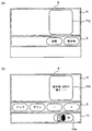
- the figure which shows the display of the operation part in the case of selecting a menu in case the cooking container is mounted in the two heating coils in the induction heating apparatus of Embodiment 1.
- the figure which shows the display of the operation part in the case of selecting a menu in case the cooking container is mounted in one heating coil in the induction heating apparatus of Embodiment 1.
- the figure which shows the display of the operation part in the case of selecting a menu in case the cooking container is mounted in one heating coil in the induction heating apparatus of Embodiment 1.
- a heating control unit for controlling the heating power of the cooking container; at least one temperature detecting means for detecting the temperature of the cooking container disposed at or near the center of the heating coil; and the heating coil at predetermined time intervals.
- a cooking vessel detection unit that supplies a high-frequency current to determine the placement state and material of the cooking vessel directly above each heating coil, and an operation unit, and the cooking vessel detection unit is adjacent to the cooking vessel detection unit.
- the operation unit detects the cooking container.
- the cooking container icon corresponding to the size and shape determined by the unit is displayed in the placement status display area, and further the cooking corresponding to the cooking container icon from the size and shape of the cooking container and the arrangement of the temperature detection means
- a cooking menu icon indicating a possible cooking menu is displayed in a menu selection area, and when the cooking menu icon is operated, cooking of the cooking menu is started and the cooking container is heated.
- the placement status of the cooking container is displayed in the placement status display area almost similar to the operation portion, the actual image and the display of the operation portion are displayed.
- the image of is easy to match.
- the configuration and display of the buttons that the user must operate regardless of how the cooking container is placed is always the same, and the operation method is the same. It is easy to understand because it doesn't change.
- the operation unit is disposed on the near side of the top plate, and a stop icon for stopping cooking is displayed in correspondence with the cooking container being cooked.
- the safety can be improved by displaying the icon in front of the icon and stopping cooking of the cooking container as soon as the stop icon is operated.
- an induction heating cooker will be described, but this configuration is an exemplification, and the present invention is not limited to the configuration described in the following embodiment, and the present disclosure It includes an induction heating device having the following technical features. Further, the present invention includes appropriately combining arbitrary configurations described in the respective embodiments described below, and the combined configurations exhibit their respective effects.
- FIG. 1 is a side cross-sectional view schematically showing a state where a cooking container is placed in a built-in type induction heating cooker that is an induction heating apparatus according to Embodiment 1 of the present disclosure.
- a cooking container 1 shown in FIG. 1 is a container for storing a cooking object such as an ingredient, and is a pot, a frying pan, a kettle or the like.
- the cooking container 1 is placed on a top plate 2 that forms part of the outer shell of the induction heating cooker.
- the top plate 2 often uses crystallized glass, but is not limited thereto.
- the heating coil 3 generates magnetic flux by a high-frequency current supplied in accordance with instructions from the heating control unit 4 and induction-heats the cooking vessel 1 on the top plate 2.
- the heating control unit 4 is connected to the operation unit 6, the inverter circuit 7, and the cooking container detection unit 5.
- the heating control unit 4 is connected to an operation unit 6 for the user of the induction heating cooker to instruct heating power and the like, and supplies power to the inverter circuit 7 in accordance with the heating instruction from the user.
- the power supplied by the heating control unit 4 is controlled so as to achieve the intended heating power.
- the cooking container detection unit 5 determines whether or not the cooking container 1 is on the heating coil 3, and the heating control unit 4 receives the result and only the heating coil 3 directly above the cooking container 1 heats up. I can do it.
- the cooking vessel detection unit 5 includes a method of detecting an electrostatic change with the cooking vessel 1 by providing an electrode, a method of detecting a change in inductance by providing a detection coil, a heating coil 3 and an inverter circuit. 7 to detect from the response of the inverter when a high-frequency current is passed through the heating coil 3, for example, using the inverter circuit 7 to supply a high-frequency current to the heating coil 3 at predetermined time intervals.
- the heating control unit 4 is often realized by a microcomputer, a DSP, a custom IC, or the like, but is not limited thereto. Moreover, the heating control part 4 and the cooking container detection part 5 may be the same.
- the heating coil 3 is relatively small as compared with the cooking container 1, and therefore the heating control unit 4 is provided to the plurality of heating coils 3 in order to heat one cooking container 1. Operates to supply power. By doing so, even if there is a change in the size or placement position of the cooking container 1, heating is performed in accordance with the cooking container 1, so that energy saving and the placement place of the cooking container 1 are not limited.
- An induction cooker having features can be provided.
- the cooking container detection unit 5 detects that the cooking container 1 of the same material is placed immediately above the heating coils 3a to 3d in the heating coil 3 of FIG. Determines that one cooking container 1 is placed across the four heating coils 3, and determines the size and shape of the cooking container 1.
- the result is displayed on the operation unit 6 (see FIG. 3), and the user simply performs a heating operation on one cooking vessel 1 using the operation unit 6, and heats the corresponding four heating coils 3.
- the control part 4 can implement
- the display area of the operation unit 6 is divided into a placement status display area 11, a menu selection area 9, and a cooking stop operation area 10. By fixing, it can be operated with the same feeling of operation no matter how the cooking container 1 is placed, and it is an easy-to-use induction heating cooker.
- the placement status display area 11 of FIG. 3 it is displayed that two cooking containers 1 are placed.
- the cooking container icon 11b of the cooking container 1 placed on the heating coil 3d at the back right side indicates that the cooking container 1 is being cooked, and further displays the thermal power and the remaining cooking time.
- a cooking container icon 11a of another cooking container 1 placed across the heating coil 3e on the left front side and the heating coil 3f adjacent to the heating coil 3e can be cooked in the cooking container 1.
- a menu is displayed in the menu selection area 9. Here, the menu that can be cooked with the cooking container icon 11a is determined based on the location and size of the cooking container 1.
- a stop icon 10 a for stopping cooking heating of the cooking container 1 is displayed in the cooking stop operation area 10.
- the stop icon 10a for stopping the cooking is displayed with an icon indicating the container on the right side back so that it can be easily and easily stopped immediately, thereby improving safety.
- the cooking stop operation area 10 is arranged at a position farthest from the heating unit above the heating coil 3 in the operation panel of the operation unit 6, so that the temperature of the operation panel which is the operation surface of the operation unit 6 is the lowest. By operating with, safety is enhanced.
- the operation unit 6 is disposed on the front side of the top plate 2, and the stop icon 10a for stopping cooking corresponding to the cooking container 1 being cooked is on the front side of the cooking container icon 11b. As soon as the stop icon 10a is operated, the cooking of the cooking container 1 is stopped.
- FIG. 4A shows a cooking container icon 11c of the cooking container 1 placed over two adjacent heating coils 3a and 3b.
- the heating control unit 4 determines a menu that can be cooked based on the place and size of the cooking container.
- cooking menu icons indicating all cooking menus that can be cooked such as “heating”, “fried food”, “baked goods”, and “hot water” are displayed. At this time, cooking of the selected cooking menu is started by operating each cooking menu icon and selecting a cooking menu.
- FIG. 4B is a display example after the “Fried food” cooking menu icon is operated to start “Fried food” cooking.
- operation icons “up”, “down”, “+”, “ ⁇ ” are displayed instead of the cooking menu icons, and the set temperature is changed by the operation of “up” or “down”. “+” Or “-” can be operated to fine-tune the set temperature.
- a stop icon 10 a for stopping “fried food” cooking is displayed in the cooking stop operation area 10 of the operation panel 6.
- the operation unit 6 is disposed on the front side of the top plate 2, and the stop icon 10a for stopping cooking corresponding to the cooking container 1 being cooked is on the front side of the cooking container icon 11d.
- the cooking of the cooking container 1 is stopped.
- one cooking container 1 is indicated by a cooking container icon 11d.
- the placement status display area 11 it is possible to select and operate from a plurality of cooking container icons, and to switch the operable display corresponding to the selected cooking container 1 to be displayed in the menu selection area 9. Further, the color of the cooking container 1 displayed in the placement status display area 11 is changed so that the selected cooking container 1 can be clearly identified.
- FIG. 4A shows a cooking container icon 11c of the cooking container 1 placed immediately above two adjacent heating coils 3a and 3b, where the cooking container 1 is placed and cooking.
- the menu selection area 9 indicates that all cooking menu icons can be selected.
- FIG. 5A shows a cooking container icon 11e of the cooking container 1 placed only directly above one heating coil 3a, and the location of the cooking container 1 and the size of the cooking container icon 11e. Now, it is shown in the menu selection area 9 that only the cooking menu icon for “heating” cooking can be selected.
- a temperature sensor temperature detection means 8 that detects the temperature of the cooking container 1 is disposed between the center of each heating coil and each heating coil 3, and is further disposed between the heating coils 3.
- the temperature sensor is provided with an infrared temperature sensor (not shown), and accurately measures the temperature of the bottom surface of the cooking container 1 in “fried food” cooking or “baked food” cooking, thereby performing temperature control. Therefore, safe cooking is realized.
- “fried food” cooking and “baked food” cooking are realized by infrared temperature sensors that are grouped and located between two or more adjacent heating coils 3, but the present invention is not necessarily limited thereto. Not what you want.
- FIG. 6A shows a cooking container icon 11g of the cooking container 1 placed immediately above the four adjacent heating coils 3a, 3b, 3c, and 3d.
- a cooking menu icon indicating that “heating” cooking and “baked goods” cooking can be selected is displayed in the place where the item is placed and the size of the cooking container icon 11 g.
- 5 (b) and 6 (b) show the display after the cooking menu is operated and cooking is started with the placed cooking container 1 as in FIG. 4 (b).
- FIG. 5 (b) shows a cooking container icon 11f indicating that the cooking container 1 placed immediately above one heating coil 3a is being “heated” cooking.
- cooking is started with the set thermal power set to 6.
- the set thermal power can be set in 10 levels from “warming” and “thermal power 1” to “thermal power 9”.
- a time-out timer can be set by operating the “ ⁇ ” or “+” operation icon to set the time and automatically stop cooking after the set time.
- a stop icon 10 a for stopping cooking is displayed in the cooking stop operation area 10 on the operation panel 6.
- the operation unit 6 is disposed on the front side of the top plate 2, and the stop icon 10a for stopping cooking corresponding to the cooking container 1 being cooked is on the front side of the cooking container icon 11f. As soon as the stop icon 10a is operated, the cooking of the cooking container 1 is stopped.
- a cooking container icon 11h indicating that the cooking container 1 placed immediately above the four heating coils 3a, 3b, 3c, and 3d is being cooked "baked goods”. It is shown.
- cooking is started at a preset temperature of “200 ° C.”.
- the set temperature can be set in increments of 10 ° C. from “140 ° C.” to “220 ° C.” using the “up” or “down” operation icon displayed in the menu selection area 9.
- a time-out timer can be set by operating the “ ⁇ ” or “+” operation icon to set the time and automatically stop cooking after the set time.
- a stop icon 10 a for stopping cooking is displayed in the cooking stop operation area 10 on the operation panel 6.
- the operation unit 6 is disposed on the front side of the top plate 2, and a stop icon 10a for stopping cooking is provided on the front side of the cooking container icon 11h corresponding to the cooking container 1 being cooked. As soon as the stop icon 10a is operated, the cooking of the cooking container 1 is stopped.
- elliptical coils are provided on the left and right sides, and a total of eight elliptical coils are used.
- heating is performed with two adjacent coils. If it is provided and the shape of the cooking container can be accurately determined, the cooking device becomes more convenient to use.
- a high-frequency current is supplied to the heating coil to detect the mounting state of the container.
- the size and shape of the container are detected by the change in the output of the temperature detection means 8 due to the change in the mounting state. It is also possible to do. Furthermore, if a change in the mounting state is detected and then a high-frequency current is supplied to the heating coil to detect the size and shape of the container, power consumption can be reduced, which is even better.
- the built-in type induction heating cooker that is the induction heating device according to the first embodiment of the present disclosure configured as described above, when a cooking container is placed on the top plate, the place where the container is placed and the size of the container By determining the sheath shape, displaying a cooking menu icon that can be cooked in the menu selection work area, and operating the icon, cooking can be started immediately, and an operation that is easy to understand can be realized. Further, by making the display of the placement status display area similar to the heating coil, it is easy to understand which cooking container is the target of operation, and the induction heating apparatus is highly reliable and safe.
- This disclosure presents an induction heating apparatus having excellent commercial value and high reliability and safety, and can be applied to various devices that perform induction heating such as an induction heating cooker.
Landscapes
- Physics & Mathematics (AREA)
- Electromagnetism (AREA)
- Engineering & Computer Science (AREA)
- Chemical & Material Sciences (AREA)
- Combustion & Propulsion (AREA)
- Mechanical Engineering (AREA)
- General Engineering & Computer Science (AREA)
- Induction Heating Cooking Devices (AREA)
Abstract
トッププレート2に調理容器1を載置すると、調理容器1が載置されているかどうか、さらに、調理容器1の大きさを判定する調理容器検出部5が、調理容器1の場所と大きさや形状を判定して調理容器アイコンを載置状況表示エリア11に表示し、操作部6のメニュー選択エリア9に調理容器アイコンに対応する調理メニューアイコンを表示し、アイコン表示を選択して調理メニューを設定することにより、操作方法が煩雑になることを防ぐことができ、わかりやすい操作を実現することができる。
Description
本開示は、トッププレート上に載置された金属製の調理用鍋などの調理容器を誘導加熱する誘導加熱装置に関する。
誘導加熱装置として一般的に用いられている誘導加熱調理器においては、例えば1つ又は2つの加熱コイルがトッププレートの直下に配設されており、当該加熱コイルによりトッププレート上に載置された調理容器である金属製の調理用鍋などを誘導加熱するよう構成されている。
また、誘導加熱調理器においては、トッププレートの直下に多数の加熱コイルを配設したマルチコイル構成が提案されている(例えば、特許文献1参照)。特許文献1に開示された誘導加熱調理器は、トッププレートの下に敷き詰められた多数の加熱コイルが近接して配置されており、調理用鍋などの調理容器をトッププレートのいずれの位置に載置しても誘導加熱可能な構成を有しており、表示部には調理容器の載置位置や大きさと相関のある表示を行い、それぞれの調理容器を表す表示の近傍に操作部を設けて使用者が操作を行うことによってそれぞれの加熱コイルの組を動作させて調理容器を加熱するように構成していた。
前述のように特許文献1に開示された誘導加熱調理器においては、複数の調理容器が載置されている場合には複数の操作部が必要となり、操作部が小さくなり操作がしづらいという課題を有する。また、載置された調理容器の位置によって操作位置が変わるため、操作に慣れにくいという課題を有する。
上記のように、トッププレートの下に多数の加熱コイルが敷き詰められるように設けられたマルチコイル構成の場合、使用者にとってはトッププレートのいずれの領域に調理容器を載置しても加熱を行うことができるため、どのようにして火力等の操作を入力するかは重要である。
本発明は、トッププレートの下に多数の加熱コイルが配設されたマルチコイル構成において、使用者にとって使い勝手の良い誘導加熱装置を提供することを目的とするものであり、トッププレート上に置いた調理容器を使用者に対して明確に表示し、調理容器の場所と大きさに応じて、調理できるメニューを表示することにより、操作が簡単で、使いやすい加熱装置を構築するとともに、高い信頼性と安全性を有する誘導加熱装置を示すものである。
本開示における誘導加熱装置は、調理物を加熱する調理容器を載置するトッププレートと、前記調理容器を加熱するために誘導磁界を発生させる複数の加熱コイルと、前記加熱コイルの高周波電流を制御して前記調理容器の加熱電力を制御する加熱制御部と、前記加熱コイルの中央または近傍に配置され前記調理容器の温度を検出する少なくとも一つ以上の温度検出手段と、所定の時間間隔で前記加熱コイルに高周波電流を供給して、各前記加熱コイルの直上の前記調理容器の載置状態及び材質を判定する調理容器検出部と、操作部と、を備え、前記調理容器検出部は、隣接した前記加熱コイルの直上に、同一材質の前記調理容器を検出した場合、同一の前記調理容器と判定して、前記調理容器の大きさ及び形状を決定し、前記操作部は、前記調理容器検出部が決定した大きさ及び形状に応じた調理容器アイコンを載置状況表示エリアに表示し、さらに、前記調理容器の大きさ及び形状と前記温度検出手段の配置から前記調理容器アイコンに対応する調理可能な調理メニューを示す調理メニューアイコンをメニュー選択エリアに表示し、前記調理メニューアイコンが操作されると、前記調理メニューの調理を開始し、調理容器が加熱されるように構成されている。
本開示における誘導加熱装置は、トッププレートに調理容器を載置するだけで、載置した場所と調理容器に応じたメニューを表示するので、調理できないメニューを選択することができず、簡単で、わかりやすい操作を実現することができる。また、調理容器を移動することにより、移動した場所に応じて、選択できる調理メニューが変わるので、最適な場所に調理容器を載置でき、信頼性および安全性の高い加熱装置を提供するものである。
第1の発明は、調理物を加熱する調理容器を載置するトッププレートと、前記調理容器を加熱するために誘導磁界を発生させる複数の加熱コイルと、前記加熱コイルの高周波電流を制御して前記調理容器の加熱電力を制御する加熱制御部と、前記加熱コイルの中央または近傍に配置され前記調理容器の温度を検出する少なくとも一つ以上の温度検出手段と、所定の時間間隔で前記加熱コイルに高周波電流を供給して、各前記加熱コイルの直上の前記調理容器の載置状態及び材質を判定する調理容器検出部と、操作部と、を備え、前記調理容器検出部は、隣接した前記加熱コイルの直上に、同一の材質の前記調理容器を検出した場合、同一の前記調理容器と判定して、前記調理容器の大きさ及び形状を決定し、前記操作部は、前記調理容器検出部が決定した大きさ及び形状に応じた調理容器アイコンを載置状況表示エリアに表示し、さらに、前記調理容器の大きさ及び形状と前記温度検出手段の配置から前記調理容器アイコンに対応する調理可能な調理メニューを示す調理メニューアイコンをメニュー選択エリアに表示し、前記調理メニューアイコンが操作されると、前記調理メニューの調理を開始し、前記調理容器が加熱されるように構成されている。
このように構成された第1の態様の誘導加熱装置は、調理容器の載置状況が操作部とほぼ相似で載置状況表示エリアに表示されるために、実際のイメージと操作部の表示とのイメージが合致しやすい。さらに、載置状況表示エリアとメニュー選択エリアを分けることによって、調理容器をどのように載置したとしても使用者が操作をしなければならないボタンの構成や表示は常に同じであり、操作方法が変わらないためにわかりやすくすることができる。
第2の発明は、特に、第1の発明において、前記操作部は前記トッププレートの手前側に配設され、調理中の前記調理容器に対応して、調理を停止させる停止アイコンを前記調理容器アイコンの手前側に表示し、前記停止アイコンが操作されるとすぐに、前記調理容器の調理を停止するようにして、安全性を高めることができる。
以下、本開示に係る誘導加熱装置の一実施の形態について、適宜図面を参照しながら詳細に説明する。例えば、既に良く知られた事項の詳細説明や実質的に同一の構成に対する重複説明を省略する場合がある。これは、以下の説明が不必要に冗長になるのを避け、当業者の理解を容易にするためである。
なお、発明者は、当業者が本開示を十分に理解するために添付図面および以下の説明を提供するものであって、これらによって特許請求の範囲に記載の主題を限定することを意図するものではない。
以下の実施の形態の誘導加熱装置においては誘導加熱調理器について説明するが、この構成は例示であり、本発明は、以下の実施の形態において説明する構成に限定されるものではなく、本開示の技術的特徴を有する誘導加熱装置を含むものである。また、本発明には、以下に述べる各実施の形態において説明する任意の構成を適宜組み合わせることを含むものであり、組み合わされた構成においてはそれぞれの効果を奏するものである。
(実施の形態1)
図1は、本開示に係る実施の形態1の誘導加熱装置であるビルトインタイプの誘導加熱調理器において、調理容器が載置されている状態を模式的に示した側面断面図である。
図1は、本開示に係る実施の形態1の誘導加熱装置であるビルトインタイプの誘導加熱調理器において、調理容器が載置されている状態を模式的に示した側面断面図である。
図1に示す調理容器1は、食材などの被調理物を入れる容器であって、鍋、フライパン、やかんなどである。
調理容器1は、誘導加熱調理器の外郭の一部を形成するトッププレート2上に載置される。トッププレート2は結晶化ガラスを使用することが多いが、それに限定するものではない。
加熱コイル3は、加熱制御部4の指示に従って供給される高周波電流によって磁束を発生し、トッププレート2上の調理容器1を誘導加熱するものである。
加熱制御部4は、操作部6と、インバータ回路7と、調理容器検出部5に接続されている。加熱制御部4は、誘導加熱調理器の使用者が加熱電力などを指示するための操作部6が接続されており、使用者からの加熱指示に従ってインバータ回路7に電力を供給し、使用者の意図した火力となるように加熱制御部4が供給する電力を制御する。
調理容器検出部5は、加熱コイル3上に調理容器1があるか否かを判定し、その結果を加熱制御部4が受けて調理容器1が直上にある加熱コイル3のみが加熱することができるようにしている。調理容器検出部5としては、電極を設けて調理容器1との静電容量の変化を検知する方法や、検知用のコイルを設けてインダクタンスの変化を検知する方法や、加熱コイル3とインバータ回路7を用いて、加熱コイル3に高周波電流を流したときのインバータの応答などから検知すること、例えば、インバータ回路7を用いて、所定の時間間隔で、加熱コイル3に高周波電流を供給して、各加熱コイル3の直上の調理容器1の載置状態と材質を判定すること、が可能であるが、どのような方法であったとしても構わない。また、インバータ回路7への入力電流、加熱コイル3の電流、加熱コイル3と共振する共振コンデンサの電圧を検知し、予め実験により材質との関係を求めることで、材質の種類、例えば、磁性と非磁性との、あるいは鉄鍋とアルミ鍋との、判別が可能である。
加熱制御部4は、マイコンやDSPやカスタムICなどによって実現されることが多いが、それに限定するものではない。また、加熱制御部4、調理容器検出部5は同一のものであっても構わない。
本発明の誘導加熱調理器では、複数の加熱コイル3が存在するため、図2に加熱コイルの配置状態を模式的に示した、トッププレート2の下方を示す、上面断面図の例を示す。
このように構成された誘導加熱調理器の場合、加熱コイル3は調理容器1と比較して相対的に小さいため、一つの調理容器1を加熱するために複数の加熱コイル3に加熱制御部4は電力を供給するように動作する。そうすることによって、調理容器1の大きさや載置位置に変化があった場合であっても、調理容器1に合わせて加熱を行うため、省エネでかつ調理容器1の載置場所が限定されないという特徴を有する誘導加熱調理器を提供することができる。
しかしながら、このように複数の加熱コイル3によって一つの調理容器1を加熱する場合に、どの加熱コイル3にどれだけ電力を供給するかを一つずつ使用者が操作するのでは使い勝手が悪いため、それを解決するのが本願の目的である。
通常、このような複数の加熱コイル3を並べたような誘導加熱調理器では、調理容器検出部5によって加熱コイル3の直上に調理容器1があるか否かを判定し、それらの判定結果からどのような大きさの調理容器1がどこに載置されているかを加熱制御部4が判定して調理容器1の大きさ及び形状が決定される。具体的には、図2の加熱コイル3のうち、加熱コイル3a~3dの直上に同一の材質の調理容器1が載置されていると調理容器検出部5が検出した場合、加熱制御部4はそれら4つの加熱コイル3にまたがるように一つの調理容器1が載置されたと判定して、調理容器1の大きさ及び形状を決定する。その結果は、操作部6に表示(図3参照)され、使用者は操作部6を使用して一つの調理容器1に対して加熱動作を行うだけで、該当の4つの加熱コイル3に加熱制御部4は電力を供給して加熱を行うことができるようにすることで、使いやすい誘導加熱調理器を実現することができる。
その際、操作パネルをどの位置に、どのような大きさで表示するかは、誘導加熱調理器の使い勝手を大きく左右する。従来、加熱コイル3が2~4個ある誘導加熱調理器の場合、それぞれの加熱コイル3に対応した操作パネルを独立して設けていた。そのような構成であっても、加熱コイル3の数が少ない場合には操作が煩雑になることはないが、本願のように加熱コイル3が多数の場合には、それぞれに操作パネルを設けて使用者が操作するのは現実的ではない。
調理容器検出部5の検出結果に応じて調理容器1毎にグルーピングして、操作するようにすることで使い勝手が向上する。しかし、このような誘導加熱調理器の場合には調理容器1の大きさに応じて動作させる加熱コイル3の数を変更することによって様々な大きさや形状の調理容器1に対して効率よく加熱できる反面、操作パネルをどのような大きさでどの位置に表示するかが問題となる。従来の誘導加熱調理器では、グルーピングして表示した調理容器1の近傍に操作パネルを表示していた。この場合、調理容器1が複数ある場合などは調理容器1の表示と操作パネルの表示が重なるために、操作パネルを小さくしか表示できないため、細かい設定をしようとすると階層が深くなるなど、使い勝手の良くないものになっていた。また、調理容器1の載置場所が変わると操作パネルの表示場所も変わるため、使用感が変わって慣れないために使いにくいという課題があった。
そこで、本願では図3に示すように操作部6の表示エリアを、載置状況表示エリア11と、メニュー選択エリア9、調理停止操作エリア10の3つに分けて、それぞれの表示エリアの役割を固定することによって、どのような調理容器1の置かれ方をしても同じ操作感で操作することができ、使い勝手の良い誘導加熱調理器とした。
図3の載置状況表示エリア11には、2つの調理容器1が載置されていることが表示されている。右側奥の加熱コイル3d上に載置されている調理容器1の調理容器アイコン11bには、当該調理容器1が加熱調理中であることが示されており、さらに火力と調理残時間とが表示されている。左側前の加熱コイル3eと、当該加熱コイル3eに隣接する加熱コイル3fとの2つにまたがって載置されたもう一つの調理容器1の調理容器アイコン11aには、当該調理容器1で調理できるメニューがメニュー選択エリア9に表示されている。ここで、この調理容器アイコン11aで調理できるメニューは、調理容器1の場所と大きさとに基づいて判定される。
さらに、調理容器1の調理加熱を停止するための停止アイコン10aが調理停止操作エリア10に表示されている。ここで、加熱調理を停止させるための停止アイコン10aには、右側奥の容器を示すアイコンを表示して、わかりやすく、簡単に、すぐに停止できるようにすることにより、安全性を高めている。また、調理停止操作エリア10は、操作部6の操作パネルにおいて最も加熱コイル3の上方の加熱部から遠い位置に配置することによって、操作部6の操作面である操作パネルの温度が最も低い部分で操作することにより、安全性を高めている。すなわち、誘導加熱調理器は、操作部6がトッププレート2の手前側に配設され、調理中の調理容器1に対応して、調理を停止させる停止アイコン10aを調理容器アイコン11bの手前側に表示し、停止アイコン10aが操作されるとすぐに、調理容器1の調理を停止するように構成されている。
次に、調理容器1が載置されてから調理を開始するまでの動作を図4、図5および図6を用いて、説明する。
図4(a)には、隣接する加熱コイル3aと加熱コイル3bの2つにまたがって載置した調理容器1の調理容器アイコン11cが示されている。調理容器検出部5が加熱コイル3aと加熱コイル3bの直上に調理容器1が載置されたことを検知して、加熱制御部4は、載置された場所と大きさから調理できるメニューを判定し、メニュー選択エリア9に「加熱」「揚げ物」「焼き物」「湯沸し」の調理可能なすべての調理メニューを示す調理メニューアイコンを表示している。この時、各調理メニューアイコンを操作して調理メニューを選択することで、当該選択された調理メニューの調理を開始する。
図4(b)は、調理メニューアイコンの「揚げ物」を操作して、「揚げ物」調理を開始した後の表示例である。メニュー選択エリア9には、調理メニューアイコンに変えて「アップ」「ダウン」「+」「-」の操作アイコンが表示され、「アップ」または「ダウン」の操作で設定温度を変更し、さらに、「+」または「-」を操作して、設定温度の微調を行える。また、操作パネル6の調理停止操作エリア10には、「揚げ物」調理を停止させるための停止アイコン10aが表示される。すなわち、誘導加熱調理器は、操作部6がトッププレート2の手前側に配設され、調理中の調理容器1に対応して、調理を停止させる停止アイコン10aを調理容器アイコン11dの手前側に表示し、停止アイコン10aが操作されるとすぐに、調理容器1の調理を停止するように構成されている。なお、本実施の形態では、1つの調理容器1に関して調理容器アイコン11dで示しているが、2つ以上の調理容器1が載置された場合には、載置状況表示エリア11に表示された複数の調理容器アイコンから選択して操作し、選択されている調理容器1に対応する操作可能な表示を切換えてメニュー選択エリア9に表示することが可能なことは、言うでもない。さらに、載置状況表示エリア11に表示された調理容器1の色を変更して、選択されている調理容器1が明確に判別できるようにしている。
図5(a)と図6(a)では、図4(a)と同様に、載置された調理容器1で、調理可能と判定された調理メニューを表示している。
図4(a)には、2つの隣接した加熱コイル3aと加熱コイル3bの直上に載置された調理容器1の調理容器アイコン11cが示され、当該調理容器1が載置された場所と調理容器アイコン11cの大きさでは、すべての調理メニューアイコンが選択可能であることがメニュー選択エリア9に示されている。
図5(a)には、1つの加熱コイル3aの直上のみに載置された調理容器1の調理容器アイコン11eが示され、当該調理容器1が載置された場所と調理容器アイコン11eの大きさでは、「加熱」調理の調理メニューアイコンだけが選択可能であることがメニュー選択エリア9に示されている。本実施の形態では、調理容器1の温度を検出する温度センサ(温度検出手段8)を各加熱コイルの中央と、それぞれの加熱コイル3の間に配置し、さらに加熱コイル3の間に配置されている温度センサは、赤外線温度センサ(図示していない)を配置し、「揚げ物」調理や「焼き物」調理において、調理容器1の底面の温度を正確に測定し、これにより、温度制御を行うことによって、安全な調理を実現している。
ただし、本実施の形態では、グルーピングされ、隣接した2つ以上の加熱コイル3の間にある赤外線温度センサにより、「揚げ物」調理と「焼き物」調理を実現しているが、必ずしも本発明を限定するものではない。
図6(a)には、隣接した4つの加熱コイル3a、加熱コイル3b、加熱コイル3c、加熱コイル3dの直上に載置された調理容器1の調理容器アイコン11gが示され、当該調理容器1が載置された場所と調理容器アイコン11gの大きさでは、「加熱」調理と「焼き物」調理の選択が可能であることを示す調理メニューアイコンがメニュー選択エリア9に示されている。
図5(b)と図6(b)では、図4(b)と同様に、載置された調理容器1で、調理メニューを操作し、調理を開始したあとの表示を示している。
図5(b)には、1つの加熱コイル3aの直上に載置された調理容器1が「加熱」調理中であることを示す調理容器アイコン11fが示されている。「加熱」調理を開始すると、設定火力を6にして調理を開始する。メニュー選択エリア9に表示された「アップ」または「ダウン」の操作アイコンにより、設定火力を「保温」と「火力1」から「火力9」までの10段階で電力を設定できる。さらに、「-」または「+」の操作アイコンを操作して、時間を設定し、設定時間後に自動的に調理を停止する切タイマーを設定できる。また、操作パネル6にある調理停止操作エリア10に調理を停止させる停止アイコン10aが表示される。すなわち、誘導加熱調理器は、操作部6がトッププレート2の手前側に配設され、調理中の調理容器1に対応して、調理を停止させる停止アイコン10aを調理容器アイコン11fの手前側に表示し、停止アイコン10aが操作されるとすぐに、調理容器1の調理を停止するように構成されている。
図6(b)には、4つの加熱コイル3a、加熱コイル3b、加熱コイル3c、加熱コイル3dの直上に載置された調理容器1が「焼き物」調理中であることを示す調理容器アイコン11hが示されている。「焼き物」調理を開始すると、設定温度を「200℃」にして調理を開始する。メニュー選択エリア9に表示された「アップ」または「ダウン」の操作アイコンにより、設定温度を「140℃」から「220℃」まで10℃刻みで温度を設定できる。さらに、「-」または「+」の操作アイコンを操作して、時間を設定し、設定時間後に自動的に調理を停止する切タイマーを設定できる。また、操作パネル6にある調理停止操作エリア10に調理を停止させる停止アイコン10aが表示される。すなわち、誘導加熱調理器は、操作部6がトッププレート2の手前側に配設され、調理中の調理容器1に対応して、調理を停止させる停止アイコン10aを調理容器アイコン11hの手前側に表示し、停止アイコン10aが操作されるとすぐに、調理容器1の調理を停止するように構成されている。
なお、本開示では、左右に4つずつ、全部で8つの楕円コイルを備え、通常の直径18cm程度の容器では、隣接した2つのコイルで加熱しているものとしているが、できるだけ小さいコイルを多く備え、調理容器の形状を正確に判定できると、より、使い勝手のより調理器となる。
なお、本開示では、加熱コイルに高周波電流を供給して、容器の載置状態を検出しているが、載置状態の変化による温度検出手段8の出力変化によって、容器の大きさや形状を検知することも考えられる。さらに、載置状態の変化を検知してから、加熱コイルに高周波電流を供給して、容器の大きさや形状を検出すると、消費電力の削減もでき、なおよい。
上記のように構成された本開示に係る実施の形態1の誘導加熱装置であるビルトインタイプの誘導加熱調理器においては、トッププレートに調理容器を載置すると、載置された場所と容器の大きさや形状を判定し、調理できる調理メニューアイコンをメニュー選択作エリアに表示し、アイコンを操作することにより、すぐに調理を開始でき、操作が分かりやすい操作を実現することができる。また、載置状況表示エリアの表示を加熱コイルと相似にすることでどの調理容器を操作の対象としているかをわかりやすく、信頼性および安全性の高い誘導加熱装置となる。
本開示は、優れた商品価値を有し、信頼性および安全性の高い誘導加熱装置を提示するものであり、例えば誘導加熱調理器などの誘導加熱を行う各種機器において適用可能である。
1 調理容器、
2 トッププレート、
3、3a、3b、3c、3d 加熱コイル、
4 加熱制御部、
5 調理容器検出部、
6 操作部、
7 インバータ回路、
8 温度検出手段、
9 メニュー選択エリア、
10 調理停止操作エリア、
11 載置状況表示エリア、
11a、11b、11c、11d、11e、11f、11g、11h 調理容器アイコン。
2 トッププレート、
3、3a、3b、3c、3d 加熱コイル、
4 加熱制御部、
5 調理容器検出部、
6 操作部、
7 インバータ回路、
8 温度検出手段、
9 メニュー選択エリア、
10 調理停止操作エリア、
11 載置状況表示エリア、
11a、11b、11c、11d、11e、11f、11g、11h 調理容器アイコン。
Claims (2)
- 調理物を加熱する調理容器を載置するトッププレートと、前記調理容器を加熱するために誘導磁界を発生させる複数の加熱コイルと、前記加熱コイルの高周波電流を制御して前記調理容器の加熱電力を制御する加熱制御部と、前記加熱コイルの中央または近傍に配置され前記調理容器の温度を検出する少なくとも一つ以上の温度検出手段と、所定の時間間隔で前記加熱コイルに高周波電流を供給して、各前記加熱コイルの直上の前記調理容器の載置状態と材質を判定する調理容器検出部と、操作部と、を備え、前記調理容器検出部は、隣接した前記加熱コイルの直上に、同一の材質の前記調理容器を検出した場合、同一の前記調理容器と判定して、前記調理容器の大きさ及び形状を決定し、前記操作部は、前記調理容器検出部が決定した大きさ及び形状に応じた調理容器アイコンを載置状況表示エリアに表示し、さらに、前記調理容器の大きさ及び形状と前記温度検出手段の配置から前記調理容器アイコンに対応する調理可能な調理メニューを示す調理メニューアイコンをメニュー選択エリアに表示し、前記調理メニューアイコンが操作されると、前記調理メニューの調理を開始する誘導加熱装置。
- 前記操作部は前記トッププレートの手前側に配設され、調理中の前記調理容器に対応して、調理を停止させる停止アイコンを前記調理容器アイコンの手前側に表示し、前記停止アイコンが操作されるとすぐに、前記調理容器の調理を停止するようにした請求項1に記載の誘導加熱装置。
Priority Applications (3)
| Application Number | Priority Date | Filing Date | Title |
|---|---|---|---|
| EP14811068.7A EP3010308B1 (en) | 2013-06-11 | 2014-06-04 | Induction heating apparatus |
| ES14811068.7T ES2661834T3 (es) | 2013-06-11 | 2014-06-04 | Aparato de calentamiento por inducción |
| JP2015522524A JP6268613B2 (ja) | 2013-06-11 | 2014-06-04 | 誘導加熱装置 |
Applications Claiming Priority (2)
| Application Number | Priority Date | Filing Date | Title |
|---|---|---|---|
| JP2013-122312 | 2013-06-11 | ||
| JP2013122312 | 2013-06-11 |
Publications (1)
| Publication Number | Publication Date |
|---|---|
| WO2014199597A1 true WO2014199597A1 (ja) | 2014-12-18 |
Family
ID=52021915
Family Applications (1)
| Application Number | Title | Priority Date | Filing Date |
|---|---|---|---|
| PCT/JP2014/002981 Ceased WO2014199597A1 (ja) | 2013-06-11 | 2014-06-04 | 誘導加熱装置 |
Country Status (4)
| Country | Link |
|---|---|
| EP (1) | EP3010308B1 (ja) |
| JP (1) | JP6268613B2 (ja) |
| ES (1) | ES2661834T3 (ja) |
| WO (1) | WO2014199597A1 (ja) |
Cited By (7)
| Publication number | Priority date | Publication date | Assignee | Title |
|---|---|---|---|---|
| JP2017150760A (ja) * | 2016-02-25 | 2017-08-31 | 株式会社アイホー | 再加熱装置 |
| WO2018042941A1 (ja) * | 2016-08-30 | 2018-03-08 | パナソニックIpマネジメント株式会社 | 誘導加熱調理器 |
| JPWO2017081859A1 (ja) * | 2015-11-13 | 2018-08-30 | パナソニックIpマネジメント株式会社 | 誘導加熱調理器 |
| KR20190066853A (ko) * | 2017-12-06 | 2019-06-14 | 엘지전자 주식회사 | 스마트 인공 지능 유도 가열 장치 |
| WO2019146950A1 (ko) * | 2018-01-23 | 2019-08-01 | 엘지전자 주식회사 | 제품의 열용량을 추정하여 동작을 제어하는 냉장고 및 방법 |
| JP2021012841A (ja) * | 2019-07-09 | 2021-02-04 | 三菱電機株式会社 | 加熱調理器、加熱調理システム、端末装置、および報知方法 |
| CN117158763A (zh) * | 2022-05-26 | 2023-12-05 | 佛山市顺德区美的电热电器制造有限公司 | 一种烹饪设备 |
Families Citing this family (9)
| Publication number | Priority date | Publication date | Assignee | Title |
|---|---|---|---|---|
| JP6851011B2 (ja) * | 2016-08-30 | 2021-03-31 | パナソニックIpマネジメント株式会社 | 誘導加熱調理器 |
| KR102509713B1 (ko) * | 2018-04-03 | 2023-03-13 | 엘지전자 주식회사 | 사용자 경험 및 사용자 인터페이스가 개선된 존프리 타입 유도 가열 장치 |
| KR102535062B1 (ko) * | 2018-04-16 | 2023-05-22 | 엘지전자 주식회사 | 사용자 경험 및 사용자 인터페이스가 개선된 하프 플렉스 타입 유도 가열 장치 |
| EP3780905B1 (en) * | 2018-04-12 | 2024-07-17 | LG Electronics Inc. | Half-flex type induction heating device enabling improved user experience and user interface |
| KR102509724B1 (ko) * | 2018-04-12 | 2023-03-13 | 엘지전자 주식회사 | 사용자 경험 및 사용자 인터페이스가 개선된 하프 플렉스 타입 유도 가열 장치 |
| DE102022129549A1 (de) * | 2022-11-09 | 2024-05-16 | Termacook Gmbh | Sensorgesteuertes Kochfeld |
| USD1101472S1 (en) | 2024-09-04 | 2025-11-11 | Sharkninja Operating Llc | Air fryer |
| USD1101481S1 (en) | 2024-09-04 | 2025-11-11 | Sharkninja Operating Llc | Air fryer adapter |
| USD1100567S1 (en) | 2024-09-04 | 2025-11-04 | Sharkninja Operating Llc | Air fryer |
Citations (5)
| Publication number | Priority date | Publication date | Assignee | Title |
|---|---|---|---|---|
| JP2007103289A (ja) * | 2005-10-07 | 2007-04-19 | Matsushita Electric Ind Co Ltd | 誘導加熱調理器 |
| JP2007294439A (ja) * | 2006-03-30 | 2007-11-08 | Mitsubishi Electric Corp | 誘導加熱調理器 |
| JP2008293871A (ja) | 2007-05-28 | 2008-12-04 | Mitsubishi Electric Corp | 誘導加熱調理器 |
| JP2009295330A (ja) * | 2008-06-03 | 2009-12-17 | Toshiba Corp | 誘導加熱調理装置 |
| JP2013062173A (ja) * | 2011-09-14 | 2013-04-04 | Mitsubishi Electric Corp | 誘導加熱調理器及びそのプログラム |
Family Cites Families (5)
| Publication number | Priority date | Publication date | Assignee | Title |
|---|---|---|---|---|
| DE102007057332A1 (de) * | 2007-11-28 | 2009-06-04 | BSH Bosch und Siemens Hausgeräte GmbH | Hausgerätanzeigevorrichtung |
| JP5203752B2 (ja) * | 2008-03-10 | 2013-06-05 | パナソニック株式会社 | 誘導加熱調理器 |
| WO2011148568A1 (ja) * | 2010-05-28 | 2011-12-01 | 三菱電機株式会社 | 誘導加熱調理器 |
| KR20110136226A (ko) * | 2010-06-14 | 2011-12-21 | 삼성전자주식회사 | 유도가열조리기 및 그 제어방법 |
| EP3270661A1 (en) * | 2011-03-28 | 2018-01-17 | Samsung Electronics Co., Ltd. | Control method of induction heating cooker |
-
2014
- 2014-06-04 EP EP14811068.7A patent/EP3010308B1/en active Active
- 2014-06-04 WO PCT/JP2014/002981 patent/WO2014199597A1/ja not_active Ceased
- 2014-06-04 JP JP2015522524A patent/JP6268613B2/ja active Active
- 2014-06-04 ES ES14811068.7T patent/ES2661834T3/es active Active
Patent Citations (5)
| Publication number | Priority date | Publication date | Assignee | Title |
|---|---|---|---|---|
| JP2007103289A (ja) * | 2005-10-07 | 2007-04-19 | Matsushita Electric Ind Co Ltd | 誘導加熱調理器 |
| JP2007294439A (ja) * | 2006-03-30 | 2007-11-08 | Mitsubishi Electric Corp | 誘導加熱調理器 |
| JP2008293871A (ja) | 2007-05-28 | 2008-12-04 | Mitsubishi Electric Corp | 誘導加熱調理器 |
| JP2009295330A (ja) * | 2008-06-03 | 2009-12-17 | Toshiba Corp | 誘導加熱調理装置 |
| JP2013062173A (ja) * | 2011-09-14 | 2013-04-04 | Mitsubishi Electric Corp | 誘導加熱調理器及びそのプログラム |
Cited By (10)
| Publication number | Priority date | Publication date | Assignee | Title |
|---|---|---|---|---|
| JPWO2017081859A1 (ja) * | 2015-11-13 | 2018-08-30 | パナソニックIpマネジメント株式会社 | 誘導加熱調理器 |
| JP2017150760A (ja) * | 2016-02-25 | 2017-08-31 | 株式会社アイホー | 再加熱装置 |
| WO2018042941A1 (ja) * | 2016-08-30 | 2018-03-08 | パナソニックIpマネジメント株式会社 | 誘導加熱調理器 |
| JPWO2018042941A1 (ja) * | 2016-08-30 | 2019-06-24 | パナソニックIpマネジメント株式会社 | 誘導加熱調理器 |
| KR20190066853A (ko) * | 2017-12-06 | 2019-06-14 | 엘지전자 주식회사 | 스마트 인공 지능 유도 가열 장치 |
| KR102388092B1 (ko) * | 2017-12-06 | 2022-04-18 | 엘지전자 주식회사 | 스마트 인공 지능 유도 가열 장치 |
| WO2019146950A1 (ko) * | 2018-01-23 | 2019-08-01 | 엘지전자 주식회사 | 제품의 열용량을 추정하여 동작을 제어하는 냉장고 및 방법 |
| JP2021012841A (ja) * | 2019-07-09 | 2021-02-04 | 三菱電機株式会社 | 加熱調理器、加熱調理システム、端末装置、および報知方法 |
| JP7308675B2 (ja) | 2019-07-09 | 2023-07-14 | 三菱電機株式会社 | 加熱調理器、加熱調理システム、端末装置、および報知方法 |
| CN117158763A (zh) * | 2022-05-26 | 2023-12-05 | 佛山市顺德区美的电热电器制造有限公司 | 一种烹饪设备 |
Also Published As
| Publication number | Publication date |
|---|---|
| JP6268613B2 (ja) | 2018-01-31 |
| EP3010308A4 (en) | 2016-06-22 |
| JPWO2014199597A1 (ja) | 2017-02-23 |
| EP3010308B1 (en) | 2017-12-13 |
| ES2661834T3 (es) | 2018-04-04 |
| EP3010308A1 (en) | 2016-04-20 |
Similar Documents
| Publication | Publication Date | Title |
|---|---|---|
| JP6268613B2 (ja) | 誘導加熱装置 | |
| JP2014044852A (ja) | 誘導加熱装置 | |
| JPWO2017064803A1 (ja) | 加熱調理システム、誘導加熱調理器、及び電気機器 | |
| EP2131626A1 (en) | Cooking device for a cooking container | |
| JP6292485B2 (ja) | 誘導加熱調理器 | |
| JP6817510B2 (ja) | 誘導加熱調理器 | |
| JP6591049B2 (ja) | 加熱調理システム及び調理装置 | |
| WO2013136577A1 (ja) | 誘導加熱調理器 | |
| JP7094417B2 (ja) | 加熱調理器 | |
| JP2016025031A (ja) | 誘導加熱調理器 | |
| JP5404826B2 (ja) | 加熱調理器 | |
| JP5233862B2 (ja) | 電磁調理器 | |
| CN104797024B (zh) | 感应加热烹调机 | |
| JP5487837B2 (ja) | 誘導加熱調理器 | |
| KR101919893B1 (ko) | 인덕션 렌지의 구동 장치 및 방법 | |
| KR102752831B1 (ko) | 피가열체의 물리적 상태에 기초하여 동작이 제어되는 전기 레인지 및 이의 제어 방법 | |
| JP5642271B2 (ja) | 誘導加熱調理器及びそのプログラム | |
| JP2012014839A (ja) | 加熱調理器 | |
| JP5945720B2 (ja) | 誘導加熱装置 | |
| JP5257542B2 (ja) | 誘導加熱調理器 | |
| JP5389201B2 (ja) | 加熱調理器 | |
| JP2010113855A (ja) | 加熱調理器 | |
| JP2018037235A (ja) | 誘導加熱調理器 | |
| JP5389200B2 (ja) | 加熱調理器 | |
| JP2014116123A (ja) | 誘導加熱調理器 |
Legal Events
| Date | Code | Title | Description |
|---|---|---|---|
| 121 | Ep: the epo has been informed by wipo that ep was designated in this application |
Ref document number: 14811068 Country of ref document: EP Kind code of ref document: A1 |
|
| ENP | Entry into the national phase |
Ref document number: 2015522524 Country of ref document: JP Kind code of ref document: A |
|
| WWE | Wipo information: entry into national phase |
Ref document number: 2014811068 Country of ref document: EP |
|
| NENP | Non-entry into the national phase |
Ref country code: DE |