WO2014199620A1 - 油井管用ねじ継手 - Google Patents
油井管用ねじ継手 Download PDFInfo
- Publication number
- WO2014199620A1 WO2014199620A1 PCT/JP2014/003056 JP2014003056W WO2014199620A1 WO 2014199620 A1 WO2014199620 A1 WO 2014199620A1 JP 2014003056 W JP2014003056 W JP 2014003056W WO 2014199620 A1 WO2014199620 A1 WO 2014199620A1
- Authority
- WO
- WIPO (PCT)
- Prior art keywords
- pin
- screw
- thread
- shoulder
- threaded joint
- Prior art date
- Legal status (The legal status is an assumption and is not a legal conclusion. Google has not performed a legal analysis and makes no representation as to the accuracy of the status listed.)
- Ceased
Links
Images


Classifications
-
- E—FIXED CONSTRUCTIONS
- E21—EARTH OR ROCK DRILLING; MINING
- E21B—EARTH OR ROCK DRILLING; OBTAINING OIL, GAS, WATER, SOLUBLE OR MELTABLE MATERIALS OR A SLURRY OF MINERALS FROM WELLS
- E21B17/00—Drilling rods or pipes; Flexible drill strings; Kellies; Drill collars; Sucker rods; Cables; Casings; Tubings
- E21B17/02—Couplings; joints
- E21B17/04—Couplings; joints between rod or the like and bit or between rod and rod or the like
- E21B17/042—Threaded
-
- F—MECHANICAL ENGINEERING; LIGHTING; HEATING; WEAPONS; BLASTING
- F16—ENGINEERING ELEMENTS AND UNITS; GENERAL MEASURES FOR PRODUCING AND MAINTAINING EFFECTIVE FUNCTIONING OF MACHINES OR INSTALLATIONS; THERMAL INSULATION IN GENERAL
- F16B—DEVICES FOR FASTENING OR SECURING CONSTRUCTIONAL ELEMENTS OR MACHINE PARTS TOGETHER, e.g. NAILS, BOLTS, CIRCLIPS, CLAMPS, CLIPS OR WEDGES; JOINTS OR JOINTING
- F16B33/00—Features common to bolt and nut
- F16B33/02—Shape of thread; Special thread-forms
-
- F—MECHANICAL ENGINEERING; LIGHTING; HEATING; WEAPONS; BLASTING
- F16—ENGINEERING ELEMENTS AND UNITS; GENERAL MEASURES FOR PRODUCING AND MAINTAINING EFFECTIVE FUNCTIONING OF MACHINES OR INSTALLATIONS; THERMAL INSULATION IN GENERAL
- F16L—PIPES; JOINTS OR FITTINGS FOR PIPES; SUPPORTS FOR PIPES, CABLES OR PROTECTIVE TUBING; MEANS FOR THERMAL INSULATION IN GENERAL
- F16L15/00—Screw-threaded joints; Forms of screw-threads for such joints
- F16L15/001—Screw-threaded joints; Forms of screw-threads for such joints with conical threads
- F16L15/004—Screw-threaded joints; Forms of screw-threads for such joints with conical threads with axial sealings having at least one plastically deformable sealing surface
-
- F—MECHANICAL ENGINEERING; LIGHTING; HEATING; WEAPONS; BLASTING
- F16—ENGINEERING ELEMENTS AND UNITS; GENERAL MEASURES FOR PRODUCING AND MAINTAINING EFFECTIVE FUNCTIONING OF MACHINES OR INSTALLATIONS; THERMAL INSULATION IN GENERAL
- F16L—PIPES; JOINTS OR FITTINGS FOR PIPES; SUPPORTS FOR PIPES, CABLES OR PROTECTIVE TUBING; MEANS FOR THERMAL INSULATION IN GENERAL
- F16L15/00—Screw-threaded joints; Forms of screw-threads for such joints
- F16L15/06—Screw-threaded joints; Forms of screw-threads for such joints characterised by the shape of the screw-thread
Definitions
- the present invention relates to threaded joints for threaded joints for threaded joints (threaded joints, for oil, country, tubulars, and more), and more particularly for searching and producing oil wells and gas wells.
- Suitable for connecting steel pipes such as OCTG (oil country tubular goods), riser pipes, and line pipes, which contain tubing and casings The present invention relates to a threaded joint for oil well pipes having excellent properties.
- Threaded joints are widely used for the connection of steel pipes used in oil industry such as oil well pipes (petroleum installation).
- API American Petroleum Institute
- standard threaded joints defined in the API have been typically used to connect steel pipes used for oil and gas exploration and production.
- wells of crude oil and natural gas have been deepened, and vertical wells, horizontal wells, directional wells, etc.
- the excavation and production environment is becoming harsh.
- the development of wells in poor environments such as the ocean and polar regions (appalling ⁇ circumstance) has increased, so compression resistance, bending resistance (bending resistance), and external pressure seal performance
- the required performance of screw joints such as (sealability against external pressure) (external pressure resistance) is diversifying.
- the use of high-performance special threaded joints (premium joints) called premium joints is increasing, and the demand for performance is also increasing.
- Premium joints usually have a taper thread (seal) thread), seal (portion) (more specifically metal touch seal (metal to metal seal)), shoulder (shoulder) (more specifically torque shoulder)
- a male thread member (externally-threaded member) formed on the end of the pipe (hereinafter referred to as a pin) and a female thread member (internally-threaded member) connecting the pins (hereinafter referred to as a box) Are called coupling-type joints.
- the taper screw is important to firmly fix the pipe joint, and the seal part plays a role of ensuring gas tightness by making metal contact between the box and the pin at this part, and the shoulder part is tightening of the joint Inside it becomes a shoulder face that acts as an abutment.
- FIG. 3 is a schematic explanatory view showing a conventional example of a premium joint for oil well pipes, which is a vertical cross-sectional view (a cross-sectional view in which a pipe axis extends in a cross section) of a threaded joint of a circular pipe.
- the screw joint includes a pin 3 and a box 1 corresponding to the pin 3, and the pin 3 is adjacent to the male screw portion 7 on the outer surface and the male screw portion 7 on the tip side of the pin 3.
- It has a nose 8 (also referred to as a pin nose) which is a lengthless portion provided with screws.
- the nose portion 8 includes a seal portion (specifically, a metal touch seal portion) 11 on an outer peripheral surface thereof, and a shoulder portion 12 on an end surface thereof.
- Corresponding box 1 has a female screw portion 5 and a seal portion, which are parts that can be screwed or contacted with the male screw portion 7, the seal portion 11, and the shoulder portion 12 of the pin 3, respectively, on the inner surface thereof. 13 and a shoulder portion 14.
- the seal portion 11 is at the tip of the pin 3, and a desired sealing performance can be realized by applying an appropriate tightening torque (make up torque).
- an appropriate tightening torque make up torque
- the tightening torque is affected by lubrication conditions, surface quality, and the like. Therefore, as a design not largely depending on these, there is a radial seal method (also referred to as a radial seal type) in which the radial component of the seal contact pressure is relatively strong.
- the radial seal type is similar to the screw joint of FIG. 3 having a seal portion at the tip of the pin in that the radial seal type has a seal portion at a site different from the shoulder portion.
- an axial contact reaction force acts on the pin tube end side, and the load flank of the threaded portion on the pin tube end side
- the maximum axial reaction force is generated on the surface (load flank face), and seizure (galling) is likely to occur.
- Patent Document 1 There is a conventional technique for preventing seizure at the end of the box by reducing the contact reaction force at the end of the box (see Patent Document 1).
- the present inventors diligently studied to solve the above-mentioned problems, and as a result, the pin tube end side thread portion at the time of tightening the threaded joint by optimizing the chamfer length of the pin screw (chamfer length of pin thread). It has been found that the contact reaction force can be reduced, thereby preventing seizure.
- the chamfer length of the pin screw means that, at the end of the thread cutting process, the threaded part (externally-threaded member) on the end of the pin tube is usually cut off at a certain cutting angle.
- the above-mentioned uniform cutting angle is called a chamfer angle (chamfer angle), and is defined by an inclination angle ⁇ from the plane perpendicular to the tube axis (where acute angle is an acute angle).
- the present invention made based on the above discovery is as follows.
- a threaded joint for oil well pipes to be a shoulder surface to be contacted, wherein the pin thread chamfer length-to-screw pitch ratio is 1.0 or more and 3.0 or less, and the oil well pipe thread having excellent seizure resistance Fitting .
- FIG. 1 is a schematic explanatory view showing an example of an embodiment of the present invention.
- FIG. 2 is a graph showing the contact reaction force for each pin thread when the threaded joint is tightened (Make-up).
- FIG. 3 is a schematic explanatory view showing a conventional example of a special threaded joint.
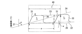
- FIG. 1 is a schematic explanatory view showing an example of an embodiment of the present invention, which is a longitudinal sectional view in the vicinity of a threaded portion (male threaded portion) at a pin tube end.
- 20 is a parallel line of tube axis
- 21 is an orthogonal line of tube axis
- 22 is a base line of the root of thread
- 23 Is the base line of the screw thread top position
- 24 is the limit line for scraping
- 30 is the load flank face
- 31 is the stubbing flank surface
- 40 is the chamfer portion of the pin screw
- L is the chamfer length of the pin screw
- ⁇ is the chamfer angle
- ⁇ is the taper angle
- 7 1 and 7 2 are the first and second threads of the first and second threads from the end of the pin tube, respectively.
- h is the thread height
- p is the thread pitch
- points A and B are the rising start point and the rising end point of the stubbing flank 31 of each thread of the pin, respectively.
- the base line 22 at the screw valley bottom position and the base line 23 at the screw thread top position are parallel to each other.
- the thread taper angle ⁇ is an intersection angle (however, an acute angle) between the pipe axis parallel line 20 and the base line 22 at the thread valley bottom position.
- the screw height h is a distance in the radial direction of the pipe from the base line 22 at the screw valley bottom position to the base line 23 at the screw thread top position.
- Thread pitch p is the distance in the tube axis direction between the point A between the threads adjacent the pin (e.g., pin first thread 71 and the pin second thread 7 2).
- the chamfer angle ⁇ is an angle formed by the limit line 24 for scraping and the tube axis orthogonal line 21.
- Converging point of chamfer angle range is an angle region of the chamfer angle ⁇ when coordinated (convergence point) to the point A of the pin first thread 71, the portion of the male screw portion 7 to enter the chamfer angle region, screws A part of the mountain is to be cut off, that is, a chamfer part 40 of a pin screw.
- the length in the tube axis direction of the chamfer portion 40 of this pin screw is the chamfer length L of the pin screw.
- the intersection of the cutting-off limit line 24 and the base line 23 at the screw thread top position is an end point on the side opposite to the pipe end of the chamfer portion 40 of the pin screw.
- the end point coincides with point B of the pin second thread 7 2.
- the end point may not always coincide with the second screw thread 7 2 at point B, where the point B of a certain one pin threads of the thread contour line of toward the falling end point of the load flank 30 In some cases, it may coincide with one point.
- the pin screw chamfer length L to screw pitch p ratio (abbreviated as chamfer length ratio) L / p is set to 1.0 or more and 3.0 or less. Give the reason.
- the portion of the male screw portion 7 from which a part of the pin thread has been scraped becomes an incomplete thread having an incomplete thread shape. Since the incomplete thread portion has lower rigidity than the complete thread portion that is a portion having a complete thread shape connected to the opposite tube end side of the incomplete thread portion, the incomplete thread portion is likely to be deformed when fastened to the female thread portion 5. As a result, the contact reaction force is dispersed and reduced in the length direction of the screw portion, and the longer the incomplete screw portion, the greater the effect of reducing the contact reaction force. However, if L / p is less than 1.0, the effect of reducing the contact reaction force is insufficient.
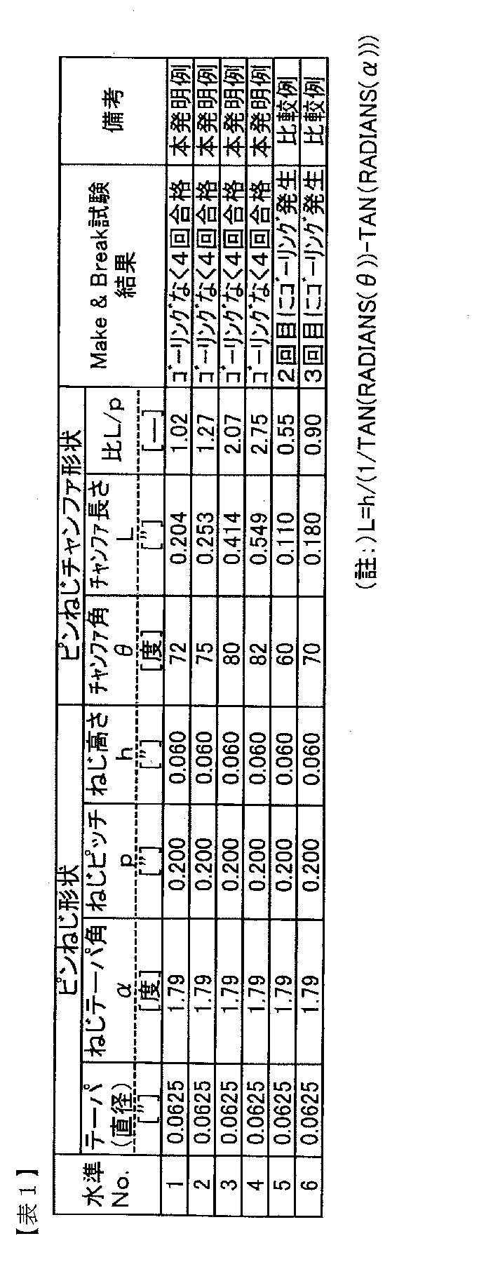
- Table 1 consists of a pin formed by threading a pipe end of a steel pipe having an outer diameter of 9-5 / 8 " ⁇ thickness of 0.545" and a corresponding box.
- a Make & Break test was repeatedly performed on the threaded joint for oil well pipes, which indicates the level of the chamfer shape of the screw, in accordance with ISO 13679: 2002, which repeatedly tightens and tightens.
- the test conditions are: thread interference (high) (high) (0.305 mm), seal interference (high) (high) (1.016 mm), tightening torque (high) (50,000 N ⁇ m) It was.
- the amount of seal interference refers to the portion to be the pin-side seal portion and the box-side seal portion when the pin drawing and the box drawing are overlapped so that their tube axes and the shoulder portions coincide with each other. It is twice the maximum value in the radial direction of the tube in the region where the part interferes (value per diameter).
- the screw interference amount is the part to be used as the pin-side screw part and the box-side screw part. This is twice the value in the radial direction of the tube in the region where the portion to be interfered with (a value per diameter).
- “taper (diameter)” in the “pin screw shape” column is the amount of change in the diameter of the thread portion per inch. When the screw taper angle ⁇ is used, it is expressed as 2 tan ⁇ . It is a value to be set.
- test results are shown in Table 1. As shown in Table 1, the inventive examples passed the Make & Break test without being baked (goring) at any level.
Landscapes
- Engineering & Computer Science (AREA)
- General Engineering & Computer Science (AREA)
- Mechanical Engineering (AREA)
- Mining & Mineral Resources (AREA)
- Life Sciences & Earth Sciences (AREA)
- Geology (AREA)
- Fluid Mechanics (AREA)
- Environmental & Geological Engineering (AREA)
- Physics & Mathematics (AREA)
- General Life Sciences & Earth Sciences (AREA)
- Geochemistry & Mineralogy (AREA)
- Non-Disconnectible Joints And Screw-Threaded Joints (AREA)
- Earth Drilling (AREA)
- Joints That Cut Off Fluids, And Hose Joints (AREA)
- Lubricants (AREA)
Abstract
Description
h=L×(1/tanθ-tanα) (1)
式(1)においてL=m×pと置いて以下の様に式を変形していくと式(2)となる。h/(m×p)=1/tanθ-tanα ⇒ 1/tanθ=tanα+h/(m×p) ⇒ tanθ=1/{tanα+h/(m×p)} ⇒
θ=tan-1[1/{tanα+h/(m×p)}] …(2)
式(2)と、本発明の要件である、L/p=m=1.0~3.0、とから、チャンファ角θは式(3)を満たす設定とすればよいことになる。
tan-1[1/{tanα+h/(1.0×p)}]≦θ≦tan-1[1/{tanα+h/(3.0×p)}] (3)
現状のねじ切削加工(threading)の技術水準(technical level)においては、式(3)を満たすチャンファ角θの設定は比較的容易なことであるから、本発明によれば、工業的生産が容易な耐焼付き性に優れた油井管用ねじ継手が得られるのである。
3 ピン
5 雌ねじ部(ボックス側)
7 雄ねじ部(ピン側)
71 ピン第1ねじ山
72 ピン第2ねじ山
8 ノーズ部(ピンノーズ)
11,13 シール部(メタルタッチシール部)
12 ショルダ部(ピン側)
14 ショルダ部(ボックス側)
20 管軸平行線
21 管軸直交線
22 ねじ谷底位置の基線
23 ねじ山頂位置の基線
30 ロードフランク面
31 スタビングフランク面
40 チャンファ部
Claims (1)
- 油井管用鋼管の管端部を占有し、雄ねじ部と、該雄ねじ部より管端側に延在するノーズ部と、該ノーズ部の先端をなすショルダ部とを有するピンと、
前記雄ねじ部とねじ結合されてねじ部をなす雌ねじ部と、前記ピンのショルダ部に当接するショルダ部とを有するボックスと、を有し、
前記ねじ結合により前記ピンと前記ボックスとが結合されて夫々のねじ部とショルダ部との間の部位で互いに相手方とメタル‐メタル接触しその接触部がシール部をなし、
前記ピンと前記ボックス夫々のショルダ部はねじ継手締付時に相手方と当接するショルダ面となる油井管用ねじ継手であって、
ピンねじチャンファ長さの対ねじピッチ比を1.0以上3.0以下としたことを特徴とする油井管用ねじ継手。
Priority Applications (4)
| Application Number | Priority Date | Filing Date | Title |
|---|---|---|---|
| US14/896,754 US9982491B2 (en) | 2013-06-14 | 2014-06-09 | Threaded joint for oil country tubular goods |
| EP14811561.1A EP2977662B1 (en) | 2013-06-14 | 2014-06-09 | Threaded joint for oil well pipe |
| BR112015028000-5A BR112015028000B1 (pt) | 2013-06-14 | 2014-06-09 | junta roscada para tubos de poços de petróleo |
| MX2015016314A MX377126B (es) | 2013-06-14 | 2014-06-09 | Junta roscada para productos tubulares de region petrolifera. |
Applications Claiming Priority (2)
| Application Number | Priority Date | Filing Date | Title |
|---|---|---|---|
| JP2013125327A JP5742885B2 (ja) | 2013-06-14 | 2013-06-14 | 耐焼付き性に優れた油井管用ねじ継手 |
| JP2013-125327 | 2013-06-14 |
Publications (1)
| Publication Number | Publication Date |
|---|---|
| WO2014199620A1 true WO2014199620A1 (ja) | 2014-12-18 |
Family
ID=52021934
Family Applications (1)
| Application Number | Title | Priority Date | Filing Date |
|---|---|---|---|
| PCT/JP2014/003056 Ceased WO2014199620A1 (ja) | 2013-06-14 | 2014-06-09 | 油井管用ねじ継手 |
Country Status (7)
| Country | Link |
|---|---|
| US (1) | US9982491B2 (ja) |
| EP (1) | EP2977662B1 (ja) |
| JP (1) | JP5742885B2 (ja) |
| AR (1) | AR096606A1 (ja) |
| BR (1) | BR112015028000B1 (ja) |
| MX (1) | MX377126B (ja) |
| WO (1) | WO2014199620A1 (ja) |
Families Citing this family (3)
| Publication number | Priority date | Publication date | Assignee | Title |
|---|---|---|---|---|
| US11505999B2 (en) | 2020-10-22 | 2022-11-22 | Frac String Solutions Llc | Leak-resistant threaded pipe connection |
| WO2024171498A1 (ja) * | 2023-02-14 | 2024-08-22 | 日本製鉄株式会社 | 鋼管用ねじ継手 |
| WO2026078756A1 (ja) * | 2024-10-07 | 2026-04-16 | Jfeスチール株式会社 | 鋼管用ねじ継手 |
Citations (6)
| Publication number | Priority date | Publication date | Assignee | Title |
|---|---|---|---|---|
| JPH0650476A (ja) * | 1992-07-31 | 1994-02-22 | Kawasaki Steel Corp | 油井管用ネジ継手 |
| JPH09126367A (ja) * | 1995-10-31 | 1997-05-13 | Kawasaki Steel Corp | 管継手 |
| JP2001021072A (ja) | 1999-07-05 | 2001-01-26 | Nippon Steel Corp | 耐焼き付き性の優れた管継手及びその加工方法 |
| JP2002061780A (ja) * | 2000-06-09 | 2002-02-28 | Sumitomo Metal Ind Ltd | 管継手 |
| US20060006647A1 (en) * | 2004-07-07 | 2006-01-12 | Hashem Ghazi J | Hybrid threaded connection for expandable tubulars |
| JP2008256023A (ja) * | 2007-04-02 | 2008-10-23 | Sumitomo Metal Ind Ltd | 鋼管用ねじ継手 |
Family Cites Families (10)
| Publication number | Priority date | Publication date | Assignee | Title |
|---|---|---|---|---|
| US4121862A (en) * | 1977-04-06 | 1978-10-24 | Exxon Production Research Company | Pipe connection |
| JPS616488A (ja) * | 1984-06-20 | 1986-01-13 | 日本鋼管株式会社 | 油井管用ネジ継手 |
| WO1999008034A1 (en) * | 1997-08-11 | 1999-02-18 | Marubeni Tubulars, Inc. | Tubular connection |
| EP0949441A4 (en) * | 1997-10-08 | 2006-09-06 | Sumitomo Metal Ind | SCREW CONNECTION FOR OIL PIPES AND METHOD FOR THE PRODUCTION THEREOF |
| WO2001094831A1 (en) * | 2000-06-07 | 2001-12-13 | Sumitomo Metal Industries, Ltd. | Taper threaded joint |
| MXPA02012145A (es) | 2000-06-09 | 2004-08-19 | Sumitomo Metal Ind | Junta de tuberia. |
| UA82694C2 (uk) * | 2003-06-06 | 2008-05-12 | Sumitomo Metal Ind | Нарізне з'єднання для сталевих труб |
| EP2002165B1 (en) * | 2006-03-31 | 2017-09-06 | Nippon Steel & Sumitomo Metal Corporation | Tubular threaded joint |
| FR2953272B1 (fr) * | 2009-11-30 | 2011-12-16 | Vallourec Mannesmann Oil & Gas | Joint filete |
| CN102352727A (zh) * | 2011-10-24 | 2012-02-15 | 大庆福斯特科技开发有限公司 | 一种8tpi油、套管螺纹连接接头 |
-
2013
- 2013-06-14 JP JP2013125327A patent/JP5742885B2/ja active Active
-
2014
- 2014-06-09 EP EP14811561.1A patent/EP2977662B1/en active Active
- 2014-06-09 MX MX2015016314A patent/MX377126B/es active IP Right Grant
- 2014-06-09 WO PCT/JP2014/003056 patent/WO2014199620A1/ja not_active Ceased
- 2014-06-09 BR BR112015028000-5A patent/BR112015028000B1/pt active IP Right Grant
- 2014-06-09 US US14/896,754 patent/US9982491B2/en active Active
- 2014-06-13 AR ARP140102260A patent/AR096606A1/es active IP Right Grant
Patent Citations (6)
| Publication number | Priority date | Publication date | Assignee | Title |
|---|---|---|---|---|
| JPH0650476A (ja) * | 1992-07-31 | 1994-02-22 | Kawasaki Steel Corp | 油井管用ネジ継手 |
| JPH09126367A (ja) * | 1995-10-31 | 1997-05-13 | Kawasaki Steel Corp | 管継手 |
| JP2001021072A (ja) | 1999-07-05 | 2001-01-26 | Nippon Steel Corp | 耐焼き付き性の優れた管継手及びその加工方法 |
| JP2002061780A (ja) * | 2000-06-09 | 2002-02-28 | Sumitomo Metal Ind Ltd | 管継手 |
| US20060006647A1 (en) * | 2004-07-07 | 2006-01-12 | Hashem Ghazi J | Hybrid threaded connection for expandable tubulars |
| JP2008256023A (ja) * | 2007-04-02 | 2008-10-23 | Sumitomo Metal Ind Ltd | 鋼管用ねじ継手 |
Non-Patent Citations (1)
| Title |
|---|
| See also references of EP2977662A4 |
Also Published As
| Publication number | Publication date |
|---|---|
| US9982491B2 (en) | 2018-05-29 |
| EP2977662A4 (en) | 2016-05-25 |
| EP2977662B1 (en) | 2019-07-24 |
| AR096606A1 (es) | 2016-01-20 |
| US20160123091A1 (en) | 2016-05-05 |
| MX377126B (es) | 2025-03-07 |
| JP2015001252A (ja) | 2015-01-05 |
| JP5742885B2 (ja) | 2015-07-01 |
| EP2977662A1 (en) | 2016-01-27 |
| BR112015028000A2 (pt) | 2017-07-25 |
| BR112015028000B1 (pt) | 2020-12-08 |
| MX2015016314A (es) | 2016-03-16 |
Similar Documents
| Publication | Publication Date | Title |
|---|---|---|
| JP7120179B2 (ja) | 油井管用ねじ継手 | |
| CN207131996U (zh) | 油井管用螺纹接头 | |
| JP5849749B2 (ja) | 管用ねじ継手 | |
| CN103527870B (zh) | 管的螺纹接头 | |
| WO2015104739A1 (ja) | 極厚肉油井管用ねじ継手 | |
| MX2013010500A (es) | Union roscada para tuberias de acero. | |
| JP5978953B2 (ja) | 管用ねじ継手 | |
| JP5704191B2 (ja) | 耐焼付き性に優れた油井管用ねじ継手 | |
| JP5803953B2 (ja) | 管接続用ねじ継手 | |
| JP5742885B2 (ja) | 耐焼付き性に優れた油井管用ねじ継手 | |
| WO2015015799A1 (ja) | 油井管用ねじ継手 | |
| JPWO2016113790A1 (ja) | 管用ねじ継手 | |
| JP5783146B2 (ja) | 鋼管用ねじ継手 | |
| JP5776222B2 (ja) | 鋼管用ねじ継手 | |
| JP6020087B2 (ja) | 管用ねじ継手 | |
| JP5779990B2 (ja) | ねじ切削方法 | |
| JP5906588B2 (ja) | 鋼管用ねじ継手の製造方法 | |
| JP2013029174A (ja) | 鋼管用ねじ継手 | |
| JPWO2020183860A1 (ja) | ねじ継手 | |
| JP6051811B2 (ja) | 管用ねじ継手 | |
| JP5779989B2 (ja) | ねじ切削方法 | |
| JP5906587B2 (ja) | 鋼管用ねじ継手の製造方法 |
Legal Events
| Date | Code | Title | Description |
|---|---|---|---|
| 121 | Ep: the epo has been informed by wipo that ep was designated in this application |
Ref document number: 14811561 Country of ref document: EP Kind code of ref document: A1 |
|
| WWE | Wipo information: entry into national phase |
Ref document number: 2014811561 Country of ref document: EP |
|
| WWE | Wipo information: entry into national phase |
Ref document number: MX/A/2015/016314 Country of ref document: MX |
|
| REG | Reference to national code |
Ref country code: BR Ref legal event code: B01A Ref document number: 112015028000 Country of ref document: BR |
|
| WWE | Wipo information: entry into national phase |
Ref document number: 14896754 Country of ref document: US |
|
| NENP | Non-entry into the national phase |
Ref country code: DE |
|
| ENP | Entry into the national phase |
Ref document number: 112015028000 Country of ref document: BR Kind code of ref document: A2 Effective date: 20151106 |