WO2014199725A1 - 電力変換装置 - Google Patents
電力変換装置 Download PDFInfo
- Publication number
- WO2014199725A1 WO2014199725A1 PCT/JP2014/061001 JP2014061001W WO2014199725A1 WO 2014199725 A1 WO2014199725 A1 WO 2014199725A1 JP 2014061001 W JP2014061001 W JP 2014061001W WO 2014199725 A1 WO2014199725 A1 WO 2014199725A1
- Authority
- WO
- WIPO (PCT)
- Prior art keywords
- connector
- hole
- connection detection
- wiring
- housing
- Prior art date
- Legal status (The legal status is an assumption and is not a legal conclusion. Google has not performed a legal analysis and makes no representation as to the accuracy of the status listed.)
- Ceased
Links
Images


Classifications
-
- B—PERFORMING OPERATIONS; TRANSPORTING
- B60—VEHICLES IN GENERAL
- B60L—PROPULSION OF ELECTRICALLY-PROPELLED VEHICLES; SUPPLYING ELECTRIC POWER FOR AUXILIARY EQUIPMENT OF ELECTRICALLY-PROPELLED VEHICLES; ELECTRODYNAMIC BRAKE SYSTEMS FOR VEHICLES IN GENERAL; MAGNETIC SUSPENSION OR LEVITATION FOR VEHICLES; MONITORING OPERATING VARIABLES OF ELECTRICALLY-PROPELLED VEHICLES; ELECTRIC SAFETY DEVICES FOR ELECTRICALLY-PROPELLED VEHICLES
- B60L3/00—Electric devices on electrically-propelled vehicles for safety purposes; Monitoring operating variables, e.g. speed, deceleration or energy consumption
- B60L3/0023—Detecting, eliminating, remedying or compensating for drive train abnormalities, e.g. failures within the drive train
- B60L3/0069—Detecting, eliminating, remedying or compensating for drive train abnormalities, e.g. failures within the drive train relating to the isolation, e.g. ground fault or leak current
-
- B—PERFORMING OPERATIONS; TRANSPORTING
- B60—VEHICLES IN GENERAL
- B60L—PROPULSION OF ELECTRICALLY-PROPELLED VEHICLES; SUPPLYING ELECTRIC POWER FOR AUXILIARY EQUIPMENT OF ELECTRICALLY-PROPELLED VEHICLES; ELECTRODYNAMIC BRAKE SYSTEMS FOR VEHICLES IN GENERAL; MAGNETIC SUSPENSION OR LEVITATION FOR VEHICLES; MONITORING OPERATING VARIABLES OF ELECTRICALLY-PROPELLED VEHICLES; ELECTRIC SAFETY DEVICES FOR ELECTRICALLY-PROPELLED VEHICLES
- B60L3/00—Electric devices on electrically-propelled vehicles for safety purposes; Monitoring operating variables, e.g. speed, deceleration or energy consumption
- B60L3/04—Cutting off the power supply under fault conditions
-
- B—PERFORMING OPERATIONS; TRANSPORTING
- B60—VEHICLES IN GENERAL
- B60L—PROPULSION OF ELECTRICALLY-PROPELLED VEHICLES; SUPPLYING ELECTRIC POWER FOR AUXILIARY EQUIPMENT OF ELECTRICALLY-PROPELLED VEHICLES; ELECTRODYNAMIC BRAKE SYSTEMS FOR VEHICLES IN GENERAL; MAGNETIC SUSPENSION OR LEVITATION FOR VEHICLES; MONITORING OPERATING VARIABLES OF ELECTRICALLY-PROPELLED VEHICLES; ELECTRIC SAFETY DEVICES FOR ELECTRICALLY-PROPELLED VEHICLES
- B60L53/00—Methods of charging batteries, specially adapted for electric vehicles; Charging stations or on-board charging equipment therefor; Exchange of energy storage elements in electric vehicles
- B60L53/10—Methods of charging batteries, specially adapted for electric vehicles; Charging stations or on-board charging equipment therefor; Exchange of energy storage elements in electric vehicles characterised by the energy transfer between the charging station and the vehicle
- B60L53/11—DC charging controlled by the charging station, e.g. mode 4
-
- B—PERFORMING OPERATIONS; TRANSPORTING
- B60—VEHICLES IN GENERAL
- B60L—PROPULSION OF ELECTRICALLY-PROPELLED VEHICLES; SUPPLYING ELECTRIC POWER FOR AUXILIARY EQUIPMENT OF ELECTRICALLY-PROPELLED VEHICLES; ELECTRODYNAMIC BRAKE SYSTEMS FOR VEHICLES IN GENERAL; MAGNETIC SUSPENSION OR LEVITATION FOR VEHICLES; MONITORING OPERATING VARIABLES OF ELECTRICALLY-PROPELLED VEHICLES; ELECTRIC SAFETY DEVICES FOR ELECTRICALLY-PROPELLED VEHICLES
- B60L53/00—Methods of charging batteries, specially adapted for electric vehicles; Charging stations or on-board charging equipment therefor; Exchange of energy storage elements in electric vehicles
- B60L53/10—Methods of charging batteries, specially adapted for electric vehicles; Charging stations or on-board charging equipment therefor; Exchange of energy storage elements in electric vehicles characterised by the energy transfer between the charging station and the vehicle
- B60L53/14—Conductive energy transfer
- B60L53/16—Connectors, e.g. plugs or sockets, specially adapted for charging electric vehicles
-
- B—PERFORMING OPERATIONS; TRANSPORTING
- B60—VEHICLES IN GENERAL
- B60L—PROPULSION OF ELECTRICALLY-PROPELLED VEHICLES; SUPPLYING ELECTRIC POWER FOR AUXILIARY EQUIPMENT OF ELECTRICALLY-PROPELLED VEHICLES; ELECTRODYNAMIC BRAKE SYSTEMS FOR VEHICLES IN GENERAL; MAGNETIC SUSPENSION OR LEVITATION FOR VEHICLES; MONITORING OPERATING VARIABLES OF ELECTRICALLY-PROPELLED VEHICLES; ELECTRIC SAFETY DEVICES FOR ELECTRICALLY-PROPELLED VEHICLES
- B60L53/00—Methods of charging batteries, specially adapted for electric vehicles; Charging stations or on-board charging equipment therefor; Exchange of energy storage elements in electric vehicles
- B60L53/60—Monitoring or controlling charging stations
- B60L53/65—Monitoring or controlling charging stations involving identification of vehicles or their battery types
-
- H—ELECTRICITY
- H01—ELECTRIC ELEMENTS
- H01R—ELECTRICALLY-CONDUCTIVE CONNECTIONS; STRUCTURAL ASSOCIATIONS OF A PLURALITY OF MUTUALLY-INSULATED ELECTRICAL CONNECTING ELEMENTS; COUPLING DEVICES; CURRENT COLLECTORS
- H01R13/00—Details of coupling devices of the kinds covered by groups H01R12/70 or H01R24/00 - H01R33/00
- H01R13/648—Protective earth or shield arrangements on coupling devices, e.g. anti-static shielding
- H01R13/658—High frequency shielding arrangements, e.g. against EMI [Electro-Magnetic Interference] or EMP [Electro-Magnetic Pulse]
- H01R13/6591—Specific features or arrangements of connection of shield to conductive members
-
- H—ELECTRICITY
- H02—GENERATION; CONVERSION OR DISTRIBUTION OF ELECTRIC POWER
- H02J—ELECTRIC POWER NETWORKS; CIRCUIT ARRANGEMENTS OR SYSTEMS FOR SUPPLYING OR DISTRIBUTING ELECTRIC POWER; SYSTEMS FOR STORING ELECTRIC ENERGY
- H02J7/00—Circuit arrangements for charging or discharging batteries or for supplying loads from batteries
- H02J7/40—Circuit arrangements for charging or discharging batteries or for supplying loads from batteries characterised by the exchange of charge or discharge related data
- H02J7/443—Circuit arrangements for charging or discharging batteries or for supplying loads from batteries characterised by the exchange of charge or discharge related data using passive battery identification means, e.g. resistors or capacitors
- H02J7/448—Circuit arrangements for charging or discharging batteries or for supplying loads from batteries characterised by the exchange of charge or discharge related data using passive battery identification means, e.g. resistors or capacitors using switches, contacts or markings, e.g. optical, magnetic or barcode
-
- H—ELECTRICITY
- H02—GENERATION; CONVERSION OR DISTRIBUTION OF ELECTRIC POWER
- H02J—ELECTRIC POWER NETWORKS; CIRCUIT ARRANGEMENTS OR SYSTEMS FOR SUPPLYING OR DISTRIBUTING ELECTRIC POWER; SYSTEMS FOR STORING ELECTRIC ENERGY
- H02J7/00—Circuit arrangements for charging or discharging batteries or for supplying loads from batteries
- H02J7/485—Circuit arrangements for charging or discharging batteries or for supplying loads from batteries with provisions for charging different types of batteries
-
- B—PERFORMING OPERATIONS; TRANSPORTING
- B60—VEHICLES IN GENERAL
- B60L—PROPULSION OF ELECTRICALLY-PROPELLED VEHICLES; SUPPLYING ELECTRIC POWER FOR AUXILIARY EQUIPMENT OF ELECTRICALLY-PROPELLED VEHICLES; ELECTRODYNAMIC BRAKE SYSTEMS FOR VEHICLES IN GENERAL; MAGNETIC SUSPENSION OR LEVITATION FOR VEHICLES; MONITORING OPERATING VARIABLES OF ELECTRICALLY-PROPELLED VEHICLES; ELECTRIC SAFETY DEVICES FOR ELECTRICALLY-PROPELLED VEHICLES
- B60L2210/00—Converter types
- B60L2210/10—DC to DC converters
-
- B—PERFORMING OPERATIONS; TRANSPORTING
- B60—VEHICLES IN GENERAL
- B60R—VEHICLES, VEHICLE FITTINGS, OR VEHICLE PARTS, NOT OTHERWISE PROVIDED FOR
- B60R16/00—Electric or fluid circuits specially adapted for vehicles and not otherwise provided for; Arrangement of elements of electric or fluid circuits specially adapted for vehicles and not otherwise provided for
- B60R16/02—Electric or fluid circuits specially adapted for vehicles and not otherwise provided for; Arrangement of elements of electric or fluid circuits specially adapted for vehicles and not otherwise provided for electric constitutive elements
- B60R16/0207—Wire harnesses
- B60R16/0215—Protecting, fastening and routing means therefor
- B60R16/0222—Grommets
-
- H—ELECTRICITY
- H01—ELECTRIC ELEMENTS
- H01R—ELECTRICALLY-CONDUCTIVE CONNECTIONS; STRUCTURAL ASSOCIATIONS OF A PLURALITY OF MUTUALLY-INSULATED ELECTRICAL CONNECTING ELEMENTS; COUPLING DEVICES; CURRENT COLLECTORS
- H01R13/00—Details of coupling devices of the kinds covered by groups H01R12/70 or H01R24/00 - H01R33/00
- H01R13/66—Structural association with built-in electrical component
- H01R13/70—Structural association with built-in electrical component with built-in switch
- H01R13/703—Structural association with built-in electrical component with built-in switch operated by engagement or disengagement of coupling parts, e.g. dual-continuity coupling part
- H01R13/7039—Structural association with built-in electrical component with built-in switch operated by engagement or disengagement of coupling parts, e.g. dual-continuity coupling part the coupling part with coding means activating the switch to establish different circuits
-
- Y—GENERAL TAGGING OF NEW TECHNOLOGICAL DEVELOPMENTS; GENERAL TAGGING OF CROSS-SECTIONAL TECHNOLOGIES SPANNING OVER SEVERAL SECTIONS OF THE IPC; TECHNICAL SUBJECTS COVERED BY FORMER USPC CROSS-REFERENCE ART COLLECTIONS [XRACs] AND DIGESTS
- Y02—TECHNOLOGIES OR APPLICATIONS FOR MITIGATION OR ADAPTATION AGAINST CLIMATE CHANGE
- Y02T—CLIMATE CHANGE MITIGATION TECHNOLOGIES RELATED TO TRANSPORTATION
- Y02T10/00—Road transport of goods or passengers
- Y02T10/60—Other road transportation technologies with climate change mitigation effect
- Y02T10/70—Energy storage systems for electromobility, e.g. batteries
-
- Y—GENERAL TAGGING OF NEW TECHNOLOGICAL DEVELOPMENTS; GENERAL TAGGING OF CROSS-SECTIONAL TECHNOLOGIES SPANNING OVER SEVERAL SECTIONS OF THE IPC; TECHNICAL SUBJECTS COVERED BY FORMER USPC CROSS-REFERENCE ART COLLECTIONS [XRACs] AND DIGESTS
- Y02—TECHNOLOGIES OR APPLICATIONS FOR MITIGATION OR ADAPTATION AGAINST CLIMATE CHANGE
- Y02T—CLIMATE CHANGE MITIGATION TECHNOLOGIES RELATED TO TRANSPORTATION
- Y02T10/00—Road transport of goods or passengers
- Y02T10/60—Other road transportation technologies with climate change mitigation effect
- Y02T10/7072—Electromobility specific charging systems or methods for batteries, ultracapacitors, supercapacitors or double-layer capacitors
-
- Y—GENERAL TAGGING OF NEW TECHNOLOGICAL DEVELOPMENTS; GENERAL TAGGING OF CROSS-SECTIONAL TECHNOLOGIES SPANNING OVER SEVERAL SECTIONS OF THE IPC; TECHNICAL SUBJECTS COVERED BY FORMER USPC CROSS-REFERENCE ART COLLECTIONS [XRACs] AND DIGESTS
- Y02—TECHNOLOGIES OR APPLICATIONS FOR MITIGATION OR ADAPTATION AGAINST CLIMATE CHANGE
- Y02T—CLIMATE CHANGE MITIGATION TECHNOLOGIES RELATED TO TRANSPORTATION
- Y02T10/00—Road transport of goods or passengers
- Y02T10/60—Other road transportation technologies with climate change mitigation effect
- Y02T10/72—Electric energy management in electromobility
-
- Y—GENERAL TAGGING OF NEW TECHNOLOGICAL DEVELOPMENTS; GENERAL TAGGING OF CROSS-SECTIONAL TECHNOLOGIES SPANNING OVER SEVERAL SECTIONS OF THE IPC; TECHNICAL SUBJECTS COVERED BY FORMER USPC CROSS-REFERENCE ART COLLECTIONS [XRACs] AND DIGESTS
- Y02—TECHNOLOGIES OR APPLICATIONS FOR MITIGATION OR ADAPTATION AGAINST CLIMATE CHANGE
- Y02T—CLIMATE CHANGE MITIGATION TECHNOLOGIES RELATED TO TRANSPORTATION
- Y02T90/00—Enabling technologies or technologies with a potential or indirect contribution to GHG emissions mitigation
- Y02T90/10—Technologies relating to charging of electric vehicles
- Y02T90/12—Electric charging stations
-
- Y—GENERAL TAGGING OF NEW TECHNOLOGICAL DEVELOPMENTS; GENERAL TAGGING OF CROSS-SECTIONAL TECHNOLOGIES SPANNING OVER SEVERAL SECTIONS OF THE IPC; TECHNICAL SUBJECTS COVERED BY FORMER USPC CROSS-REFERENCE ART COLLECTIONS [XRACs] AND DIGESTS
- Y02—TECHNOLOGIES OR APPLICATIONS FOR MITIGATION OR ADAPTATION AGAINST CLIMATE CHANGE
- Y02T—CLIMATE CHANGE MITIGATION TECHNOLOGIES RELATED TO TRANSPORTATION
- Y02T90/00—Enabling technologies or technologies with a potential or indirect contribution to GHG emissions mitigation
- Y02T90/10—Technologies relating to charging of electric vehicles
- Y02T90/14—Plug-in electric vehicles
-
- Y—GENERAL TAGGING OF NEW TECHNOLOGICAL DEVELOPMENTS; GENERAL TAGGING OF CROSS-SECTIONAL TECHNOLOGIES SPANNING OVER SEVERAL SECTIONS OF THE IPC; TECHNICAL SUBJECTS COVERED BY FORMER USPC CROSS-REFERENCE ART COLLECTIONS [XRACs] AND DIGESTS
- Y02—TECHNOLOGIES OR APPLICATIONS FOR MITIGATION OR ADAPTATION AGAINST CLIMATE CHANGE
- Y02T—CLIMATE CHANGE MITIGATION TECHNOLOGIES RELATED TO TRANSPORTATION
- Y02T90/00—Enabling technologies or technologies with a potential or indirect contribution to GHG emissions mitigation
- Y02T90/10—Technologies relating to charging of electric vehicles
- Y02T90/16—Information or communication technologies improving the operation of electric vehicles
- Y02T90/167—Systems integrating technologies related to power network operation and communication or information technologies for supporting the interoperability of electric or hybrid vehicles, i.e. smartgrids as interface for battery charging of electric vehicles [EV] or hybrid vehicles [HEV]
-
- Y—GENERAL TAGGING OF NEW TECHNOLOGICAL DEVELOPMENTS; GENERAL TAGGING OF CROSS-SECTIONAL TECHNOLOGIES SPANNING OVER SEVERAL SECTIONS OF THE IPC; TECHNICAL SUBJECTS COVERED BY FORMER USPC CROSS-REFERENCE ART COLLECTIONS [XRACs] AND DIGESTS
- Y04—INFORMATION OR COMMUNICATION TECHNOLOGIES HAVING AN IMPACT ON OTHER TECHNOLOGY AREAS
- Y04S—SYSTEMS INTEGRATING TECHNOLOGIES RELATED TO POWER NETWORK OPERATION, COMMUNICATION OR INFORMATION TECHNOLOGIES FOR IMPROVING THE ELECTRICAL POWER GENERATION, TRANSMISSION, DISTRIBUTION, MANAGEMENT OR USAGE, i.e. SMART GRIDS
- Y04S30/00—Systems supporting specific end-user applications in the sector of transportation
- Y04S30/10—Systems supporting the interoperability of electric or hybrid vehicles
- Y04S30/14—Details associated with the interoperability, e.g. vehicle recognition, authentication, identification or billing
Definitions
- the present invention relates to a power conversion device, and more particularly to a power conversion device mounted on an automobile that obtains driving power by an electric motor.
- An automobile that obtains driving power by an electric motor is a low voltage for operating a high voltage storage battery for driving an electric motor used as power and auxiliary equipment such as a vehicle light or a radio.
- a voltage storage battery is provided.
- Such a vehicle is equipped with a power conversion device (DC-DC converter device) that performs power conversion from a high voltage storage battery to a low voltage storage battery or power conversion from a low voltage storage battery to a high voltage storage battery.
- the DC-DC converter device is housed in the same housing as that housed in an independent housing or other devices required for the vehicle (for example, an inverter device for driving an electric motor). Any of these.
- a DC-DC converter device has a circuit for converting a DC high voltage power source supplied from the vehicle side to a DC low voltage power source (or converting from a DC low voltage power source supplied from the vehicle side to a DC high voltage power source).
- Patent Document 1 the DC high-voltage power supplied from the vehicle side is supplied to the DC-DC converter device via the high-voltage dedicated connector via the power transmission line.
- This high voltage dedicated connector is generally provided with a connection detection line that can detect in a circuit whether or not the connector is securely engaged, mainly for safety reasons.
- connection detection line provided in the high voltage line connector is arranged to determine whether or not the high voltage power line is properly fitted in the connector part, so it is connected to the contact terminal of the high voltage power line in the connector part.
- the contact terminals of the detection lines are formed close to each other.
- the high voltage line connector portion must be adjacent to the high voltage power line at a short distance. As a result, noise superimposed on the high voltage power line may be radiated to the connection detection line due to spatial propagation.
- an object of the present invention is to effectively suppress the noise superimposed on the power line from being mixed into the connection detection line.
- a power converter includes a connector having wiring for transmitting DC power, and a housing in which the connector is disposed, and the connector determines whether the connector is connected to an external circuit.
- An opening connected to the connector is formed in the housing, and an annular core formed of a magnetic material is inserted into the opening, and the annular core has a through hole.
- the wiring and the connection detection wiring are introduced into the casing through the through hole of the annular core.
- the noise itself superimposed on the power line can be reduced, and the noise superimposed on the power line can be effectively suppressed from being mixed into the connection detection line.
- FIG. 3 It is an example of a circuit block diagram of the high voltage power supply power line and the connection detection line in the DC-DC converter of this embodiment.
- a circuit configuration diagram of a high voltage power supply line and a connection detection line which is a configuration example different from FIG.
- the vehicle side connector 300 which employ
- the apparatus side connector 200 which employ
- FIG. 2 is a configuration example of an annular core member 500. This is an example in which the device-side connector 200 and the housing 101 are assembled.
- FIG. 3 is a perspective view illustrating a configuration example in which the apparatus-side connector 200 and the annular core member 500 are incorporated in the housing 101.
- FIG. 6 is a perspective view illustrating a configuration example in which a partition member 600 is incorporated into a housing 101.
- FIG. 5 is a perspective view illustrating a configuration example in which a partition member 600 is incorporated into a housing 101. It is a top view sectional drawing when cut
- FIG. 9 is a side sectional view when cut along a section B in FIG. 8.
- FIG. 1 is an example of a circuit configuration diagram of a high voltage power source power line and a connection detection line in the high voltage connector portion of the DC-DC converter apparatus 100 of the present embodiment.
- a DC-DC converter is described as an example, but the present invention can also be applied to other power conversion devices in which the power line and the connection detection line are included in the same connector.
- a high voltage connector is described as a representative example, but the voltage does not depend on the voltage.
- the high-voltage connector described above includes a vehicle-side connector 300 and a device-side connector 200.
- the high-voltage power supply of several hundred volts supplied from the vehicle side reaches the vehicle-side connector 300 via the high-voltage power supply power wiring 310 in the high-voltage power supply wiring cable 350 as shown in the circuit configuration diagram of FIG. .
- the DC-DC converter device 100 is provided with a device-side connector 200 that fits into the vehicle-side connector 300.
- the device-side connector 200 and the DC-DC converter internal power circuit are connected by a high-voltage power supply power line 210.
- the high-voltage power supply circuit is connected to the DC-DC converter internal power circuit, and high-voltage power is supplied.
- connection detection lines 220 and 320 for detecting the engagement state of the high voltage connector are provided in the high voltage connector as shown in FIG.
- the connection detection lines 220 and 320 in FIG. 1 are the simplest example, and use the two-terminal connection detection line and have the following configuration.
- the connection detection line 320 of the vehicle-side connector 300 has a configuration in which two terminals are short-circuited by a wiring material, and is connected to the other device-side connector 200 and the internal circuit (control circuit etc.) side of the DC-DC converter device.
- a connection detection signal generation circuit 270 and a connection detection signal detection circuit 280 are provided.
- the high-voltage power supply power line 310 is connected to the high-voltage power supply power line 210, and the connection detection line 320 is also connected to the connection detection line 220.
- the connection detection signal detection circuit 280 calculates and detects the electrical signal states of both terminals of the connection detection line 220, whereby the connection state of the high voltage connector can be detected on the DC-DC converter device 100 side.
- the number of terminals and the circuit method used for connection detection are not limited to the above, and other methods may be used as long as they are electrically detected.
- FIG. 2 is another configuration example of the circuit configuration of the high voltage power supply line and the connection detection line in the high voltage connector portion of the DC-DC converter apparatus 100.
- the connection detection signal generation circuit 270 and the connection detection signal detection circuit 280 may be configured in the DC-DC converter apparatus 100 to which the high voltage connector is directly connected as shown in FIG. 1, but as shown in FIG.
- the detection line 220 may be wired over a plurality of products, and the connection detection signal generation circuit 270 and the connection detection signal detection circuit 280 may be arranged in another device 900 to which the high voltage connector is not directly connected.
- the high voltage power supply power line 210 and the connection detection line 220 are introduced into the DC-DC converter device 100 from the device-side connector 200.
- the introduction unit An annular core member 500 is disposed on the surface.
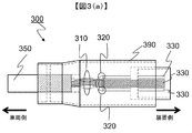
- FIG. 3 is a configuration example of the vehicle-side connector 300 adopting the circuit configuration of FIG.
- FIG. 3A is a side view of the vehicle-side connector 300.
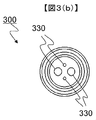
- FIG. 3B is a side view when the vehicle-side connector 300 is viewed from the DC-DC converter device 100 side.
- the vehicle-side connector 300 connects a high-voltage power supply wiring cable 350 connected to a high-voltage power supply circuit of the vehicle with the device-side connector 200 installed on the DC-DC converter device 100 side, and connects a plurality of electric circuits together.
- the vehicle-side connector 300 includes two high-voltage power supply wirings 310, two connection detection lines 320, and contact terminals 330 to which the respective wirings are connected.
- the contact terminal 330 is fitted to a contact terminal 230 of the device-side connector 200 described later to make electrical connection.
- the high-voltage power supply wiring 310 has one end wired to the contact terminal 330 and the other end wired to the vehicle-side high-voltage power supply circuit. Both ends of the connection detection line 320 are wired to one contact terminal 330. Therefore, four contact terminals 330 are provided in the vehicle-side connector 300.
- connection detection line 320 is wired as short as possible by a wiring material that is not particularly shielded.
- FIG. 4 is a configuration example of the device-side connector 200 adopting the circuit configuration of FIG.
- FIG. 4A is a side view of the device-side connector 200 viewed from the fitting direction with the vehicle-side connector 300.
- FIG. 4B is a side view of the device-side connector 200.
- FIG. 4C is a side view when the device-side connector 200 is viewed from the inside of the DC-DC converter device.
- the device-side connector 200 is connected and fitted to the vehicle-side connector 300, and functions to collectively connect a plurality of electric circuits wired to the vehicle-side connector 300 and a plurality of electric circuits introduced into the DC-DC converter device 100.
- the apparatus-side connector 200 includes two high-voltage power supply lines 210, two connection detection lines 220, and contact terminals 230 to which the respective wirings are connected.
- the contact terminal 230 is fitted to the contact terminal 330 of the vehicle-side connector 300 described above to make electrical connection.
- the high voltage power supply power line 210 has one end wired to the contact terminal 230 and the other end wired to an internal power circuit (not shown) of the DC-DC converter device.
- One end of each connection detection line 220 is wired to the contact terminal 230, and the other end is wired to the control circuit (not shown) side of the DC-DC converter device.
- four connection terminals 230 are provided.
- connection detection line 220 connection detection line 230
- connection terminal 230 connection detection line 230
- the conductive metal connector outer shell 290 has a shape to be fitted and connected to the conductive metal connector outer shell 390 of the vehicle-side connector, and is electrically connected. This configuration is aimed at the noise shielding effect by the housing potential in the connector fitting connection portion, but is not essential.
- connection detection line 220 is wired by a wiring material that is not particularly shielded, but a twisted wire or a shielded wire may be used.
- the connection detection line 220 is inserted through the tube 240 in order to bundle a plurality of wires or to physically protect the wires, but this is not always necessary.
- the conductive metal connector outer shell 290 of the device-side connector 200 has a plurality of screw holes 293 for fixing and holding to the housing of the DC-DC converter device, a cylindrical housing introduction portion 291, and this cylinder. And an O-ring 292 that suppresses intrusion of water or the like into the housing from the housing introduction portion 291.
- FIG. 5 is a configuration example of the annular core member 500.
- the annular core member 500 includes an annular magnetic core 510 formed of a magnetic material and an exterior member 520.
- the annular magnetic core 510 is an annular member in which a through hole 511 is formed.
- the exterior member 520 is an insulating member that covers the outer periphery of the annular magnetic core 510.
- the annular magnetic core 510 used in the present embodiment is an annular core having an outer shape similar to the cylindrical housing introduction portion 291 of FIG.
- the outer shape of the core shape is not particularly limited as long as the core shape is a ring shape, the shape of the housing introduction portion 291 of the device-side connector 200, the ease of processing of the housing 101 of the DC-DC converter device 100, and the like. May be selected as appropriate.
- the periphery of the annular magnetic core 510 is composed of an exterior member 520 for electrically insulating the core material.
- the exterior member 520A and the exterior member 520B are configured with two pieces, but the exterior member 520 is not limited to the illustrated example, and other methods (for example, resin coating, An insulating film coating method) may be employed.
- the core material for example, Ni—Zn-based core material
- the insulation itself may not be necessary, and thus the exterior member 520 itself is not essential.
- FIG. 6 shows an example in which the apparatus-side connector 200 and the housing 101 are assembled.
- the housing 101 is provided with a screw hole 193 for fixing and holding the device-side connector 200 and an opening (mounting / wiring hole) 120 that matches the shape of the housing introduction portion 291 of the device-side connector 200.
- the device-side connector 200 is attached and fixed to the opening 120 from the outside of the housing 101.
- the housing 101 is formed with an attachment portion protruding from the outer wall surface of the housing 101 in order to attach and fix the apparatus-side connector 200.
- the attachment portion is provided from the outer wall surface of the housing 101 in order to ensure contact between the O-ring 292 provided in the housing introduction portion 291 of the apparatus-side connector 200 and the inner wall of the opening 120 and to form a screw hole 193. It protrudes. Further, by projecting from the outer wall surface of the housing 101, the storage depth of the annular core member 500 stored in the opening 120 is ensured. Further, the vehicle-side connector 300 can be easily attached, and the assemblability is improved.
- the device-side connector 200 is attached to the housing 101 by passing a screw through a screw hole 293 formed in the device-side connector 200 and a screw hole 193 formed in the housing 101.
- the conductive metal connector outer shell 290 of the device-side connector 200 is directly fixed to the housing 101 and thereby connected to the same potential as the housing 101.
- annular core member 500 and a partition member 600 are attached to the opposite side of the apparatus-side connector 200 across the casing 101, that is, inside the casing 101.
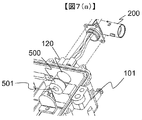
- FIG. 7A is a perspective view showing a configuration example in which the apparatus-side connector 200 and the annular core member 500 are incorporated in the housing 101.
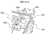
- FIG. 7B is a perspective view illustrating a configuration example in which the partition member 600 is incorporated into the housing 101.
- the device-side connector 200 is attached to the opening 120 formed in the housing 101.
- the annular core member 500 is attached to the opening 120 from the inside of the housing 101 as shown in FIG. Then, the high-voltage power supply wiring 210 and the connection detection line 220 of the device-side connector 200 are introduced into the housing 101 through the through hole 501 formed in the annular core member 500.
- the opening 120 inside the casing 101 to which the annular core member 500 is attached is naturally processed according to the outer shape of the annular core member 500, and the annular core member 500 is stored in the casing wall surface. .
- the entire annular core member 500 is accommodated in the casing wall surface, but a configuration may be adopted in which the entirety is not accommodated and a part protrudes.
- the common mode noise suppression filter circuit can be configured. That is, as shown in FIG. 1 or FIG. 2, the high-voltage power supply power wiring 210 and the connection detection wiring 220 are arranged on each circuit board inside the DC-DC converter device 100. By passing through the annular core member 500, the common mode noise superimposed on the wiring can be removed at a location closer to the noise mixing point.
- annular core member 500 of the present embodiment is accommodated in the opening 120 of the housing 101, and the above functions can be realized without increasing the size of the wiring part.
- FIG. 8 is a perspective view illustrating a configuration example in which the partition member 600 is incorporated into the housing 101.
- the partition member 600 is disposed at a position facing the annular core member 500 as shown in FIG. 7B in a state where the annular core member 500 is inserted into the opening 120 of the housing 101.
- the partition member 600 is fixed to the housing 101 in a state where the annular core member 500 is held and fixed to the housing 101.
- a method for fixing the partition member 600 to the housing 101 for example, as shown in FIG. 8, there is a method such as fastening with screws.
- FIG. 9A is a top view cross-sectional view when cut along a cross section A in FIG.
- FIG. 9B is a cross-sectional side view taken along the section B of FIG.
- the partition member 600 has a partition wall 610, a core fixing portion 620, and a screwing hole 630.
- the screwing holes 630 are used to fix the partition member 600 to the housing 101.
- the core fixing portion 620 is formed so that the region other than the region where the through hole 501 of the annular core member 500 is formed overlaps the projected portion of the core fixing portion 620 when viewed from the axial direction of the through hole 501. Is done.
- the core fixing portion 620 is formed in a convex cross-sectional shape so as to push the annular core member 500 into the opening 120 of the housing 101, and the tip of the convex cross-sectional shape pushes the annular core member 500 toward the outside of the housing 101.
- Configure as follows That is, as shown in FIG. 9B, the annular core member 500 is pressed and held in the direction of the wall surface of the housing 101 at the tip of the convex cross-sectional shape. Therefore, the annular core member 500 is sandwiched between the inner wall of the opening 120 formed in the housing 101 and the core fixing portion 620.
- the core fixing portion 620 closes a part of the opening of the through hole 501 so that the opening region is a region on one side and a region on the other side of the core fixing portion 620. And divided into two.
- the high voltage power supply power wiring 210 and the connection detection wiring 220 that penetrate the annular core member 500 are laid on one side with respect to the core fixing portion 620, and the connection detection wiring 220 is connected to the core fixing portion 620. On the other hand, it is arranged to be laid on the other side.
- the core fixing unit 620 is a wiring process after the high-voltage power supply wiring 210 and the connection detection wiring 220 pass through the through hole 501 of the annular core member 500 in a state where the partition member 600 is fixed to the housing 101.
- the shape does not necessarily have a convex cross section, and any shape that can suppress the wiring intersection and can fix the annular core member 500 may be used.
- the partition wall 610 of the partition member 600 protrudes from a part of the core fixing portion 620 toward the outer side of the housing 101.
- the partition wall 610 protrudes into the through hole 501 of the annular core member 500 fixedly held in the opening 120 of the housing 101. Thereby, the space of the through-hole 501 of the annular core member 500 is divided into two spaces, one space and the other space of the partition wall 610.
- the high voltage power supply wiring 210 is laid in a space on one side with respect to the partition wall 610 in the space in the through hole 501 of the annular core member 500.
- the connection detection wiring 220 is laid in the space on the other side with respect to the partition wall 610 in the space in the through hole 501 of the annular core member 500.
- the high voltage power supply wiring 210 laid on the right side with respect to the casing opening 120 is also arranged on the right side in the through hole 501 of the annular core member 500, and the casing opening 120
- the connection detection wiring 220 laid on the left side is also arranged on the left side in the through hole 501 of the annular core member 500.
- the high-voltage power supply power wiring 210 is positioned to the right and the connection detection wiring 220 is positioned to the left by the core fixing portion 620 formed in a convex cross-sectional shape.
- the core fixing portion 620 and the partition wall 610 divide the space in the left-right direction, but naturally the division direction is not limited to the left-right direction, and should be changed according to the wiring laying direction. Further, the number of divided spaces is not necessarily divided into two, and may be changed depending on the number of wires, and the wall surface shape is not essential as long as the partition shape can be maintained.
- the partition member 600 may be comprised with an insulator, a conductor may be sufficient and it may comprise it combining an insulator and a conductor. If the partition wall 610 of the partition member 600 and the core fixing portion 620 having a convex cross section are used as conductors and the same reference potential (GND potential) as that of the housing 101 is applied, the partition shape portion can obtain an electrical shielding effect. This is more effective for suppressing noise contamination due to propagation.
- the annular core member 500 is attached from the inside of the housing 101, but may be attached from the outside of the housing 101. That is, before attaching the device-side connector 200, the annular core member 500 is inserted into the opening 120 from the outside of the housing 101, and then the device-side connector 200 is attached. Even in this case, the same effect can be obtained by changing a part of the convex cross-sectional shape wall of the partition member 600 described above.
Landscapes
- Engineering & Computer Science (AREA)
- Power Engineering (AREA)
- Transportation (AREA)
- Mechanical Engineering (AREA)
- Life Sciences & Earth Sciences (AREA)
- Sustainable Development (AREA)
- Sustainable Energy (AREA)
- Dc-Dc Converters (AREA)
- Electric Propulsion And Braking For Vehicles (AREA)
- Details Of Connecting Devices For Male And Female Coupling (AREA)
- Hybrid Electric Vehicles (AREA)
Abstract
Description
101 筐体
120 開口部
193 ネジ穴
200 装置側コネクタ
210 高電圧電源電力配線
220 接続検知線
230 接点端子
240 チューブ
270 接続検知信号発生回路
280 接続検知信号検出回路
290 導電金属製コネクタ外殻
291 筐体導入部
292 Oリング
293 ネジ止め用穴
300 車両側コネクタ
310 高電圧電源電力配線
320 接続検知線
330 接点端子
350 高電圧電源配線ケーブル
390 導電金属製コネクタ外殻
500 環状コア部材
501 貫通孔
510 環状磁性体コア
511 貫通孔
520 外装部材
600 仕切り部材
610 仕切り壁
620 コア固定部
630 ネジ止め用穴
900 他装置
Claims (4)
- 直流電力を伝達する配線を有するコネクタと、
前記コネクタが配設される筐体と、を備え、
前記コネクタは、当該コネクタが外部回路と接続されているかどうかを検知する接続検知配線を有し、
前記筐体には、前記コネクタと繋がる開口部が形成され、
前記開口部には、磁性体により形成される環状コアが挿入され、
前記環状コアは、貫通孔が形成される環状部材であり、
前記配線及び前記接続検知配線は、前記環状コアの前記貫通孔を通って前記筐体内部に導入される電力変換装置。 - 請求項1に記載された電力変換装置であって、
仕切り部材を備え、
前記仕切り部材は、前記環状コアの前記貫通孔の軸線上に配置され、
前記仕切り部材は、前記貫通孔の開口の一部を塞ぐことで当該開口領域を分割し、
前記配線は、前記貫通孔を通り前記仕切り部材に対して一方側に敷設され、
前記接続検知配線は、前記貫通孔を通り前記仕切り部材に対して他方側に敷設される電力変換装置。 - 請求項2に記載された電力変換装置であって、
前記仕切り部材は、コア固定部を有し、
前記コア固定部は、前記貫通孔の軸線方向から見たときに、前記環状コアの前記貫通孔が形成されている領域以外の領域と当該コア固定部の射影部が重なるように配置され、
前記環状コアは、前記開口部の内壁と前記コア固定部の間に挟持される電力変換装置。 - 請求項2又は3に記載の電力変換装置であって、
前記仕切り部材は、前記環状コアの前記貫通孔内部まで突出する仕切り壁を有し、
前記配線は、前記貫通孔内部において、前記仕切り壁に対して一方側に敷設され、
前記接続検知配線は、前記貫通孔内部において、前記仕切り壁に対して他方側に敷設される電力変換装置。
Priority Applications (4)
| Application Number | Priority Date | Filing Date | Title |
|---|---|---|---|
| JP2015522624A JPWO2014199725A1 (ja) | 2013-06-10 | 2014-04-18 | 電力変換装置 |
| EP14811732.8A EP3010102B1 (en) | 2013-06-10 | 2014-04-18 | Power conversion device |
| US14/893,392 US9561728B2 (en) | 2013-06-10 | 2014-04-18 | Power conversion device |
| CN201480031422.3A CN105247749B (zh) | 2013-06-10 | 2014-04-18 | 电力变换装置 |
Applications Claiming Priority (2)
| Application Number | Priority Date | Filing Date | Title |
|---|---|---|---|
| JP2013121409 | 2013-06-10 | ||
| JP2013-121409 | 2013-06-10 |
Publications (1)
| Publication Number | Publication Date |
|---|---|
| WO2014199725A1 true WO2014199725A1 (ja) | 2014-12-18 |
Family
ID=52022027
Family Applications (1)
| Application Number | Title | Priority Date | Filing Date |
|---|---|---|---|
| PCT/JP2014/061001 Ceased WO2014199725A1 (ja) | 2013-06-10 | 2014-04-18 | 電力変換装置 |
Country Status (5)
| Country | Link |
|---|---|
| US (1) | US9561728B2 (ja) |
| EP (1) | EP3010102B1 (ja) |
| JP (1) | JPWO2014199725A1 (ja) |
| CN (1) | CN105247749B (ja) |
| WO (1) | WO2014199725A1 (ja) |
Cited By (3)
| Publication number | Priority date | Publication date | Assignee | Title |
|---|---|---|---|---|
| JP2020120039A (ja) * | 2019-01-25 | 2020-08-06 | 株式会社豊田自動織機 | 電力変換装置 |
| WO2021106144A1 (ja) * | 2019-11-28 | 2021-06-03 | 三菱電機株式会社 | 充放電装置 |
| JP2021182847A (ja) * | 2020-05-14 | 2021-11-25 | 日本電産エレシス株式会社 | インバータ装置、モータユニット、および車両 |
Families Citing this family (2)
| Publication number | Priority date | Publication date | Assignee | Title |
|---|---|---|---|---|
| DE102016121168B3 (de) * | 2016-11-07 | 2018-03-15 | Lisa Dräxlmaier GmbH | Geschirmte elektrische leitungsanordnung |
| DE102017113920B4 (de) * | 2017-06-23 | 2022-02-24 | Iav Gmbh Ingenieurgesellschaft Auto Und Verkehr | Ladeanschlusskühler und Fahrzeug mit Ladeanschlusskühler |
Citations (4)
| Publication number | Priority date | Publication date | Assignee | Title |
|---|---|---|---|---|
| JP2001185891A (ja) * | 1999-12-24 | 2001-07-06 | Nec Corp | ノイズ除去フィルタの取り付け構造 |
| US20050208798A1 (en) * | 2004-03-22 | 2005-09-22 | Ohtsuka Co., Ltd. | Electromagnetic wave shielding structure |
| JP2011015579A (ja) * | 2009-07-03 | 2011-01-20 | Honda Motor Co Ltd | 電力変換装置 |
| JP2012178937A (ja) | 2011-02-28 | 2012-09-13 | Hitachi Automotive Systems Ltd | 電力変換装置 |
Family Cites Families (8)
| Publication number | Priority date | Publication date | Assignee | Title |
|---|---|---|---|---|
| JPS5839216A (ja) * | 1981-08-31 | 1983-03-07 | アイシン・エィ・ダブリュ株式会社 | 油圧機器における電線の連結封止方法および装置 |
| JPH0537173A (ja) * | 1991-07-31 | 1993-02-12 | Canon Inc | 電子機器の電磁波防止構造 |
| JPH05136592A (ja) * | 1991-11-12 | 1993-06-01 | Fuji Electric Co Ltd | インバータ装置 |
| JP3386343B2 (ja) * | 1997-06-30 | 2003-03-17 | 住友電装株式会社 | コネクタ |
| JP3308878B2 (ja) * | 1997-10-22 | 2002-07-29 | 矢崎総業株式会社 | グロメット |
| JPH11214941A (ja) * | 1998-01-22 | 1999-08-06 | Nec Corp | ノイズフィルタ |
| JP2008028267A (ja) * | 2006-07-24 | 2008-02-07 | Fanuc Ltd | 電気回路ユニットのシール構造 |
| JP5455887B2 (ja) * | 2010-12-27 | 2014-03-26 | 日立オートモティブシステムズ株式会社 | 電力変換装置 |
-
2014
- 2014-04-18 EP EP14811732.8A patent/EP3010102B1/en active Active
- 2014-04-18 CN CN201480031422.3A patent/CN105247749B/zh active Active
- 2014-04-18 JP JP2015522624A patent/JPWO2014199725A1/ja active Pending
- 2014-04-18 WO PCT/JP2014/061001 patent/WO2014199725A1/ja not_active Ceased
- 2014-04-18 US US14/893,392 patent/US9561728B2/en active Active
Patent Citations (4)
| Publication number | Priority date | Publication date | Assignee | Title |
|---|---|---|---|---|
| JP2001185891A (ja) * | 1999-12-24 | 2001-07-06 | Nec Corp | ノイズ除去フィルタの取り付け構造 |
| US20050208798A1 (en) * | 2004-03-22 | 2005-09-22 | Ohtsuka Co., Ltd. | Electromagnetic wave shielding structure |
| JP2011015579A (ja) * | 2009-07-03 | 2011-01-20 | Honda Motor Co Ltd | 電力変換装置 |
| JP2012178937A (ja) | 2011-02-28 | 2012-09-13 | Hitachi Automotive Systems Ltd | 電力変換装置 |
Non-Patent Citations (1)
| Title |
|---|
| See also references of EP3010102A4 |
Cited By (6)
| Publication number | Priority date | Publication date | Assignee | Title |
|---|---|---|---|---|
| JP2020120039A (ja) * | 2019-01-25 | 2020-08-06 | 株式会社豊田自動織機 | 電力変換装置 |
| JP7077979B2 (ja) | 2019-01-25 | 2022-05-31 | 株式会社豊田自動織機 | 電力変換装置 |
| WO2021106144A1 (ja) * | 2019-11-28 | 2021-06-03 | 三菱電機株式会社 | 充放電装置 |
| JPWO2021106144A1 (ja) * | 2019-11-28 | 2021-12-09 | 三菱電機株式会社 | 充放電装置 |
| JP2021182847A (ja) * | 2020-05-14 | 2021-11-25 | 日本電産エレシス株式会社 | インバータ装置、モータユニット、および車両 |
| JP7612963B2 (ja) | 2020-05-14 | 2025-01-15 | ニデックエレシス株式会社 | インバータ装置、モータユニット、および車両 |
Also Published As
| Publication number | Publication date |
|---|---|
| JPWO2014199725A1 (ja) | 2017-02-23 |
| CN105247749B (zh) | 2017-11-17 |
| EP3010102A4 (en) | 2017-02-15 |
| US20160114691A1 (en) | 2016-04-28 |
| CN105247749A (zh) | 2016-01-13 |
| US9561728B2 (en) | 2017-02-07 |
| EP3010102B1 (en) | 2022-06-08 |
| EP3010102A1 (en) | 2016-04-20 |
Similar Documents
| Publication | Publication Date | Title |
|---|---|---|
| US9966704B2 (en) | Fixing structure of shield connector | |
| JP5654306B2 (ja) | 導電路接続構造 | |
| US8253021B2 (en) | Motor cable device | |
| JP5638898B2 (ja) | ワイヤハーネス配索構造及びシールドカバー | |
| JP5844572B2 (ja) | ワイヤハーネス止水構造及びワイヤハーネス | |
| WO2014199725A1 (ja) | 電力変換装置 | |
| JP2014038793A (ja) | コネクタ | |
| WO2015108201A1 (ja) | 活電部保護構造及びコネクタ | |
| JP6114135B2 (ja) | 保護カバー構造 | |
| KR101821874B1 (ko) | 하우징, 회로 조립체, 구동 조립체 및 회로 조립체를 생성하는 방법 | |
| JP2013105714A (ja) | コネクタ付きケーブル | |
| JP6334359B2 (ja) | シールドコネクタの固定構造 | |
| JP2016032388A (ja) | ワイヤハーネス | |
| JP2012230850A (ja) | 充電用コネクタ | |
| JP2013223341A (ja) | ワイヤハーネス | |
| CN111066101B (zh) | 线束 | |
| WO2014148446A1 (ja) | 電線のシールド構造 | |
| JP5985971B2 (ja) | 防水コネクタ | |
| JP2019003807A (ja) | コネクタ | |
| JP6772854B2 (ja) | ワイヤハーネス | |
| JP2010055924A (ja) | コネクタ取付構造 | |
| JP2020177740A (ja) | コネクタおよびケーブル | |
| JP7726734B2 (ja) | ワイヤハーネスの配索構造、及び、ワイヤハーネス | |
| JP6373031B2 (ja) | シールド構造 | |
| JP6210971B2 (ja) | 止水構造及びワイヤハーネス |
Legal Events
| Date | Code | Title | Description |
|---|---|---|---|
| 121 | Ep: the epo has been informed by wipo that ep was designated in this application |
Ref document number: 14811732 Country of ref document: EP Kind code of ref document: A1 |
|
| ENP | Entry into the national phase |
Ref document number: 2015522624 Country of ref document: JP Kind code of ref document: A |
|
| WWE | Wipo information: entry into national phase |
Ref document number: 14893392 Country of ref document: US |
|
| WWE | Wipo information: entry into national phase |
Ref document number: 2014811732 Country of ref document: EP |
|
| NENP | Non-entry into the national phase |
Ref country code: DE |