WO2014199772A1 - エンジン始動装置およびエンジン始動制御方法 - Google Patents
エンジン始動装置およびエンジン始動制御方法 Download PDFInfo
- Publication number
- WO2014199772A1 WO2014199772A1 PCT/JP2014/063009 JP2014063009W WO2014199772A1 WO 2014199772 A1 WO2014199772 A1 WO 2014199772A1 JP 2014063009 W JP2014063009 W JP 2014063009W WO 2014199772 A1 WO2014199772 A1 WO 2014199772A1
- Authority
- WO
- WIPO (PCT)
- Prior art keywords
- motor
- battery
- engine
- current value
- current
- Prior art date
- Legal status (The legal status is an assumption and is not a legal conclusion. Google has not performed a legal analysis and makes no representation as to the accuracy of the status listed.)
- Ceased
Links
Images

Classifications
-
- F—MECHANICAL ENGINEERING; LIGHTING; HEATING; WEAPONS; BLASTING
- F02—COMBUSTION ENGINES; HOT-GAS OR COMBUSTION-PRODUCT ENGINE PLANTS
- F02N—STARTING OF COMBUSTION ENGINES; STARTING AIDS FOR SUCH ENGINES, NOT OTHERWISE PROVIDED FOR
- F02N11/00—Starting of engines by means of electric motors
- F02N11/08—Circuits specially adapted for starting of engines
- F02N11/0862—Circuits specially adapted for starting of engines characterised by the electrical power supply means, e.g. battery
-
- F—MECHANICAL ENGINEERING; LIGHTING; HEATING; WEAPONS; BLASTING
- F02—COMBUSTION ENGINES; HOT-GAS OR COMBUSTION-PRODUCT ENGINE PLANTS
- F02N—STARTING OF COMBUSTION ENGINES; STARTING AIDS FOR SUCH ENGINES, NOT OTHERWISE PROVIDED FOR
- F02N11/00—Starting of engines by means of electric motors
- F02N11/08—Circuits specially adapted for starting of engines
- F02N11/087—Details of the switching means in starting circuits, e.g. relays or electronic switches
-
- H—ELECTRICITY
- H02—GENERATION; CONVERSION OR DISTRIBUTION OF ELECTRIC POWER
- H02P—CONTROL OR REGULATION OF ELECTRIC MOTORS, ELECTRIC GENERATORS OR DYNAMO-ELECTRIC CONVERTERS; CONTROLLING TRANSFORMERS, REACTORS OR CHOKE COILS
- H02P1/00—Arrangements for starting electric motors or dynamo-electric converters
- H02P1/02—Details of starting control
- H02P1/04—Means for controlling progress of starting sequence in dependence upon time or upon current, speed, or other motor parameter
-
- F—MECHANICAL ENGINEERING; LIGHTING; HEATING; WEAPONS; BLASTING
- F02—COMBUSTION ENGINES; HOT-GAS OR COMBUSTION-PRODUCT ENGINE PLANTS
- F02N—STARTING OF COMBUSTION ENGINES; STARTING AIDS FOR SUCH ENGINES, NOT OTHERWISE PROVIDED FOR
- F02N11/00—Starting of engines by means of electric motors
- F02N11/08—Circuits specially adapted for starting of engines
- F02N11/0814—Circuits specially adapted for starting of engines comprising means for controlling automatic idle-start-stop
-
- F—MECHANICAL ENGINEERING; LIGHTING; HEATING; WEAPONS; BLASTING
- F02—COMBUSTION ENGINES; HOT-GAS OR COMBUSTION-PRODUCT ENGINE PLANTS
- F02N—STARTING OF COMBUSTION ENGINES; STARTING AIDS FOR SUCH ENGINES, NOT OTHERWISE PROVIDED FOR
- F02N15/00—Other power-operated starting apparatus; Component parts, details, or accessories, not provided for in, or of interest apart from groups F02N5/00 - F02N13/00
- F02N15/02—Gearing between starting-engines and started engines; Engagement or disengagement thereof
- F02N15/04—Gearing between starting-engines and started engines; Engagement or disengagement thereof the gearing including disengaging toothed gears
- F02N15/06—Gearing between starting-engines and started engines; Engagement or disengagement thereof the gearing including disengaging toothed gears the toothed gears being moved by axial displacement
- F02N15/067—Gearing between starting-engines and started engines; Engagement or disengagement thereof the gearing including disengaging toothed gears the toothed gears being moved by axial displacement the starter comprising an electro-magnetically actuated lever
-
- F—MECHANICAL ENGINEERING; LIGHTING; HEATING; WEAPONS; BLASTING
- F02—COMBUSTION ENGINES; HOT-GAS OR COMBUSTION-PRODUCT ENGINE PLANTS
- F02N—STARTING OF COMBUSTION ENGINES; STARTING AIDS FOR SUCH ENGINES, NOT OTHERWISE PROVIDED FOR
- F02N11/00—Starting of engines by means of electric motors
- F02N11/08—Circuits specially adapted for starting of engines
- F02N11/087—Details of the switching means in starting circuits, e.g. relays or electronic switches
- F02N2011/0874—Details of the switching means in starting circuits, e.g. relays or electronic switches characterised by said switch being an electronic switch
-
- F—MECHANICAL ENGINEERING; LIGHTING; HEATING; WEAPONS; BLASTING
- F02—COMBUSTION ENGINES; HOT-GAS OR COMBUSTION-PRODUCT ENGINE PLANTS
- F02N—STARTING OF COMBUSTION ENGINES; STARTING AIDS FOR SUCH ENGINES, NOT OTHERWISE PROVIDED FOR
- F02N11/00—Starting of engines by means of electric motors
- F02N11/08—Circuits specially adapted for starting of engines
- F02N2011/0881—Components of the circuit not provided for by previous groups
- F02N2011/0888—DC/DC converters
-
- F—MECHANICAL ENGINEERING; LIGHTING; HEATING; WEAPONS; BLASTING
- F02—COMBUSTION ENGINES; HOT-GAS OR COMBUSTION-PRODUCT ENGINE PLANTS
- F02N—STARTING OF COMBUSTION ENGINES; STARTING AIDS FOR SUCH ENGINES, NOT OTHERWISE PROVIDED FOR
- F02N2200/00—Parameters used for control of starting apparatus
- F02N2200/02—Parameters used for control of starting apparatus said parameters being related to the engine
- F02N2200/022—Engine speed
-
- F—MECHANICAL ENGINEERING; LIGHTING; HEATING; WEAPONS; BLASTING
- F02—COMBUSTION ENGINES; HOT-GAS OR COMBUSTION-PRODUCT ENGINE PLANTS
- F02N—STARTING OF COMBUSTION ENGINES; STARTING AIDS FOR SUCH ENGINES, NOT OTHERWISE PROVIDED FOR
- F02N2200/00—Parameters used for control of starting apparatus
- F02N2200/04—Parameters used for control of starting apparatus said parameters being related to the starter motor
- F02N2200/041—Starter speed
-
- F—MECHANICAL ENGINEERING; LIGHTING; HEATING; WEAPONS; BLASTING
- F02—COMBUSTION ENGINES; HOT-GAS OR COMBUSTION-PRODUCT ENGINE PLANTS
- F02N—STARTING OF COMBUSTION ENGINES; STARTING AIDS FOR SUCH ENGINES, NOT OTHERWISE PROVIDED FOR
- F02N2200/00—Parameters used for control of starting apparatus
- F02N2200/06—Parameters used for control of starting apparatus said parameters being related to the power supply or driving circuits for the starter
- F02N2200/063—Battery voltage
-
- F—MECHANICAL ENGINEERING; LIGHTING; HEATING; WEAPONS; BLASTING
- F02—COMBUSTION ENGINES; HOT-GAS OR COMBUSTION-PRODUCT ENGINE PLANTS
- F02N—STARTING OF COMBUSTION ENGINES; STARTING AIDS FOR SUCH ENGINES, NOT OTHERWISE PROVIDED FOR
- F02N2250/00—Problems related to engine starting or engine's starting apparatus
- F02N2250/02—Battery voltage drop at start, e.g. drops causing ECU reset
-
- F—MECHANICAL ENGINEERING; LIGHTING; HEATING; WEAPONS; BLASTING
- F02—COMBUSTION ENGINES; HOT-GAS OR COMBUSTION-PRODUCT ENGINE PLANTS
- F02N—STARTING OF COMBUSTION ENGINES; STARTING AIDS FOR SUCH ENGINES, NOT OTHERWISE PROVIDED FOR
- F02N2300/00—Control related aspects of engine starting
- F02N2300/10—Control related aspects of engine starting characterised by the control output, i.e. means or parameters used as a control output or target
- F02N2300/106—Control of starter current
-
- F—MECHANICAL ENGINEERING; LIGHTING; HEATING; WEAPONS; BLASTING
- F02—COMBUSTION ENGINES; HOT-GAS OR COMBUSTION-PRODUCT ENGINE PLANTS
- F02N—STARTING OF COMBUSTION ENGINES; STARTING AIDS FOR SUCH ENGINES, NOT OTHERWISE PROVIDED FOR
- F02N2300/00—Control related aspects of engine starting
- F02N2300/10—Control related aspects of engine starting characterised by the control output, i.e. means or parameters used as a control output or target
- F02N2300/108—Duty cycle control or pulse width modulation [PWM]
Definitions
- the present invention relates to a vehicle engine starter and an engine start control method.
- An engine starter is an engine starter for starting an engine by transmitting a rotational force of a direct current motor driven by a battery to the engine, and acquires a battery voltage of the battery.
- a target current value calculating unit that calculates a target current value of a motor current supplied from the battery to the DC motor based on the battery voltage acquired by the battery voltage acquiring unit; and a target of the motor current value of the motor current.
- a motor current control unit that controls a circuit element through which the motor current flows and is connected to the DC motor so as to approach the current value.
- An engine start control method is an engine start control method for controlling engine start for starting the engine by transmitting the rotational force of a direct current motor driven by a battery to the engine. Is connected to the DC motor so that the target current value of the motor current supplied from the battery to the DC motor is calculated based on the battery voltage and the motor current value of the motor current approaches the target current value. The circuit element through which the motor current flows is controlled.
- the engine can be quickly started within a range in which the electrical components supplied with power by the battery are not reset.
- Recent automobiles are equipped with an idle stop system that temporarily stops the engine when predetermined conditions are satisfied during operation for the purpose of saving energy resources and protecting the environment.
- this idle stop system for example, when the driver stops the vehicle due to a signal or the like, the engine is automatically stopped, and after that, when the driver requests to restart or the engine needs to be operated.
- the engine will automatically restart when A so-called pinion push-out starter motor pushes out the pinion, the pinion engages with a ring gear directly connected to the engine shaft, and the engine is started by cranking by the starter motor.
- the energization of the motor is controlled by the switching element when the engine is restarted, and the duty ratio is gradually increased by PWM control to increase the applied voltage of the motor, thereby preventing a battery voltage drop immediately after the energization starts.
- An engine starting device is known.
- the conventional engine starter since the battery current is controlled so as to decrease with time, the output torque of the starter motor decreases, the engine cannot be cranked sufficiently, and the engine restart takes time. There is a fear.
- the actual battery voltage may be lower than the allowable battery voltage, and the electrical component may be reset.
- the engine starter and the engine start control method according to the present invention restarts the engine as quickly as possible within the allowable range of the battery voltage drop, and also keeps the battery voltage effect within the allowable range even when the state of the battery changes. Can be fastened.
- the engine starter and the engine start control method according to the present invention are particularly suitable when the engine is restarted in an idle stop system.
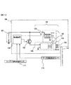
- FIG. 1 is a configuration diagram of a vehicle engine starting device 100 and related devices according to an embodiment of the present invention.
- Engine starter 100 includes a starter 101, a switch 106 for energizing magnet switch 102, a switching element 107 for energizing motor 105, and a control device 109.
- Starter 101 includes a magnet switch 102, a pinion gear 103, and a motor 105.
- the motor 105 is a so-called DC motor, and a rotational driving force is generated by applying a DC voltage.
- the magnet switch 102 pulls the lever 111 when necessary so that the one-way clutch 108 moves on the motor rotation shaft and meshes with the ring gear 104 that is directly connected to the engine shaft.
- the motor 105 is rotated by energizing the motor 105, and the rotational force of the motor 105 is transmitted to the ring gear 104 through the one-way clutch 108, and an engine (not shown) rotates. .
- the control device 109 performs normal fuel injection control, ignition control, air control (electronic control throttle), and controls idle stop based on various information such as brake pedal state and vehicle speed.
- the motor rotation detection sensor 110 detects the rotation of the motor 105. Information on the detected motor rotation speed is input to the control device 109. Instead of directly detecting the rotation of the motor 105 by the motor rotation detection sensor 110, the rotation speed of the motor 105 may be detected indirectly using the engine rotation detected by the engine rotation detection sensor 112.
- the magnet switch 102 is controlled by the control device 109 via the switch 106.
- the switch 106 is, for example, a mechanical relay switch.
- the energization of the motor 105 is also PWM controlled by the control device 109 via the switching element 107.
- the switching element 107 is a switching element using a semiconductor such as a MOSFET, for example.
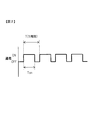
- FIG. 2 is an explanatory diagram of a PWM control energization signal used for energization control for the motor 105 included in the engine starter 100.
- the control device 109 outputs the PWM signal shown in FIG. 2 as an energization signal.
- the switching element 107 performs on / off control of energization to the motor 105.
- the length T of one cycle of the PWM control is 0.1 ms when the frequency of the PWM control is set to 10 KHz, for example.
- the frequency of PWM control is determined so that the control is sufficiently faster than the electric time constant of the motor.
- the energization ratio D in the PWM control is defined as the ratio of the energized section in one cycle.
- the energization ratio D is expressed as a ratio of a section T ON [s] in which the motor is energized in one cycle and the length T [s] of one cycle as in the following equation (1).
- the energization ratio D is a variable whose value can be changed between 0.0 and 1.0.
- the control device 109 controls the energization amount to the motor by changing the energization ratio D.
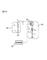
- FIG. 3 shows a simple circuit diagram of the battery 301 and the starter 101.
- many devices are driven by a battery in an automobile, but only a starter 101 including a battery 301 and a motor 105 driven by the battery 301 is shown here.
- Current flowing through the battery 301 (battery current) I b is equal to the motor current I m flowing through the motor 105.
- the output voltage (battery voltage) V b [V] of the battery 301 is determined by the following equation (2).
- the battery voltage V b is because it is determined by the battery current I b, if control of the battery current I b to a predetermined value, the battery voltage V b can be controlled to a predetermined value. If charging of the battery 301 is insufficient, an initial voltage V 0 which battery 301 may be lower than the fully charged state. Further, due to aging of the battery 301 or the like, the internal resistance Rb of the battery 301 may increase, and the battery voltage Vb when the battery current Ib flows may decrease.
- the battery voltage V b decreases even if the same battery current I b flows, and an allowable battery voltage, for example, an electrical component is a battery. It may happen that the operating voltage required to operate in response to the power supply from 301 falls below.
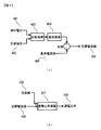
- FIG. 4 is a diagram showing a calculation method of a target current value (described later) of the motor current and a motor energization ratio in the PWM control described above. These calculations are performed by the control device 109.
- the control device 109 acquires a battery voltage V b detected by a battery voltage detection device (not shown) or the like, that is, a detection voltage 401 from the battery voltage detection device or the like. As shown in FIG. 4A, the control device 109 compares the acquired detection voltage 401 with a preset target voltage 402 by a comparison operation 403.
- the target voltage 402 is determined in advance based on the minimum operating voltage of an electrical component or the like, and is stored in the control device 109.
- the control device 109 compares the detection voltage 401 and the target voltage 402, the control device 109 calculates a difference between the two voltage values.
- the current conversion 404 converts the voltage value difference into a current using a predetermined constant, and adds a current proportional to the voltage value difference to the reference current value 405.
- the voltage value difference is a negative value
- the current proportional to the voltage value difference is reduced from the reference current value 405.
- a method of increasing or decreasing the current in proportion to the voltage difference is called so-called proportional control.
- a so-called PID control may be used in which the current is controlled based on the voltage difference and the differential value, or based on the voltage difference and the integral value.
- the predetermined constant used when converting the difference between the voltage values into the current is a feedback gain determined by an experiment, and convergence is slowed down if this is reduced.
- a predetermined conversion table may be used instead of the predetermined constant.
- Reference current value 405 when the difference between the voltage value is not the battery voltage V b by the voltage drop of the battery 301 so as to prevent below the minimum operating voltage, such as electrical components, are set in advance.
- the voltage drop of the battery 301 is caused by supplying a motor current I m (corresponding to the battery current I b ) indicating a current value equal to the target current value 409 from the battery 301 to the motor 105.
- the control device 109 stores the preset reference current value 405 in this way.
- the control device 109 acquires the motor rotation speed of the motor 105 from the motor rotation detection sensor 110.
- the control device 109 controls the switching element 107 so that the current value of the motor current I m (corresponding to the battery current I b ) approaches the target current value 409 based on the motor rotation speed thus obtained and the detection voltage 401.
- the energization ratio to be output is determined by the energization ratio calculation 407 using the information on the motor rotation speed with respect to the target current value 409. Details of the energization ratio calculation 407 will be described with reference to FIG.
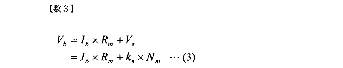
- the battery voltage V b [V] is It can be represented by (3).
- Expression (4) corresponds to a state where energization to the motor 105 is continued. According to the research of the inventors of the present invention, it has been found that the current can be approximated by the following equation (5) with respect to the energization ratio D in PWM control. When Expression (5) is used, the current can be controlled to be constant by changing the energization ratio D of the PWM control.
- the current I b flowing through the battery in the PWM control in this embodiment is proportional to the square of the current ratio D.
- the motor current I m flowing through the motor 105 of the starter 101 for equal to the battery current I b
- the motor current I m is the current ratio D when PWM controlling power supply to the DC motor 105 2 It can be approximated to be proportional to the power. This approximation is theoretically determined after experimental observation by the inventors' research.
- Equation (5) is an approximation that is established only in a range in which one cycle of PWM can be regarded as being sufficiently fast with respect to the electric time constant of the motor, and the battery current I b is the constant, the motor rotation speed N m and the energization. It is determined by two variables composed of the ratio D. To reversely use this approximation and determine the energization ratio D so as to obtain a predetermined battery current I b , Equation (5) is transformed into the following Equation (6).
- the battery current I b is set to the target current value 409, and then the energization ratio D is determined by the motor rotation speed N m .
- the energization ratio D calculated by the equation (6) exceeds 1.0, the energization ratio is set to 1.0.
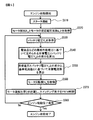
- FIG. 5 is a flowchart showing the contents of the engine start control method performed by the control device 109 in the engine start device 100 according to the present embodiment.
- control device 109 shown in FIG. 1 connects starter 101 and an engine (not shown).
- the pinion gear 103 of FIG. 1 is pushed out and meshed with the ring gear 104 directly connected to the engine.
- the idle stop method in which the starter 101 and the engine are in a connected state is applied, the starter 101 and the engine are already in a connected state when a start request is generated during the idle stop. In that case, the process in step S510 need not be performed.
- step S520 the control unit 109 acquires a counter electromotive voltage coefficient k e of the motor resistance R m and the motor which has been stored in advance.
- step S530 the control unit 109 obtains the battery voltage V b detected by the battery voltage detecting device (not shown) or the like.
- step S540 the controller 109 calculates the difference between the target voltage 402 and the battery voltage V b determined based on the minimum operating voltage, such as electrical equipment.
- step S550 the control device 109 calculates the target current value 409 by the procedure shown in FIG. 4A based on the difference between the target voltage 402 and the battery voltage Vb and the reference current value 405 stored in advance. To do.
- step S560 control device 109 acquires motor rotation speed N m from motor rotation detection sensor 110.
- control device 109 calculates the energization ratio D of PWM control using equation (6) using the variables and constants obtained in the respective processing steps from step S520 to S560, and the waveform of PWM control.
- a signal is output to the switching element 107 to control the switching element 107.
- Current starts to flow to the motor 105 by PWM control of the switching element 107 by the control device 109, torque of the motor 105 is transmitted to the engine, and the engine starts to rotate.
- control device 109 continues the processing in steps 530 to S570 until the engine start completion condition shown in step S580 is satisfied.
- an engine start completion condition in step S580 for example, it is assumed that the engine speed is equal to or higher than a predetermined speed.
- the controller 109 detects the battery voltage V b and the motor rotational speed N m at fixed intervals (e.g., 2ms interval), updates the calculated energization duty D output. By doing this, the battery current is almost constant from the start of motor energization to the completion of engine start, so the battery voltage Vb becomes almost constant because of the set current value, and is kept within the allowable range and close to the allowable value. It is done.
- Many automobiles are equipped with an engine rotation detection sensor 112 for detecting the engine speed, as shown in FIG.
- By indirectly calculating the rotation speed of the motor 105 of the starter 101 from the detected engine rotation speed it is not necessary to mount the motor rotation detection sensor 110, leading to cost reduction.
- the following equation (7) can be used.
- the rotational speed conversion coefficient g in Expression (7) can be obtained from the gear ratio between the engine and the motor 105. Specifically, when the motor 105 and the engine are connected by the pinion gear 103 and the ring gear 104, the gear ratio determined by the number of teeth of the pinion gear 103 and the ring gear 104, and the motor 105 and the pinion gear 103 in the starter 101 If a speed reduction mechanism is provided between the two, the rotation speed conversion coefficient g can be obtained by the speed reduction ratio of the speed reduction mechanism.
- Rotational speed conversion coefficient g is may be stored in advance in the control device 109, converts the sensed engine speed N e by the internal control unit 109 to the motor rotation speed N m.
- a method for estimating the motor speed when a deviation occurs between the calculated value and the actual motor speed when the motor speed is obtained indirectly by calculating from the engine speed will be described.
- Many starters 101 are provided with a one-way clutch 108 while transmitting the rotational force from the motor 105 to an engine (not shown), and are configured to transmit the rotational force only from the starter 101 side.
- the engine can be rotated by the rotational force of the motor 105, but the engine does not rotate the motor 105. Therefore, the motor rotational speed obtained indirectly from the actual motor rotational speed calculated from the engine rotational speed is calculated. May show higher values. At that time, the motor rotation speed is estimated.
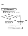
- FIG. 6 is a flowchart showing a procedure for estimating the rotation speed of the motor 105. It is assumed that when the engine speed jumps due to combustion, the clutch is disconnected and the motor 105, which is in an almost no load state, increases its speed at a constant inclination. Under such an assumption, an upper limit is set for the increase in the number of revolutions per control cycle with respect to the indirectly obtained motor revolution number N m , so that the motor revolution number is estimated for a sudden increase in engine revolution.
- the rotation speed N m of the motor is obtained indirectly on the basis of the engine speed N e of engine speed sensor 112 has detected, it allows the rotational speed N m of the motor is deviated from the actual motor speed
- the energization ratio D is calculated using the estimated motor rotation speed Nm_out estimated in consideration of the characteristics. This is repeated for each control period, and the calculation result before one control period is stored in the control device as Nm_out t-1 .
- an upper limit value ⁇ N is set in advance as an upper limit of the increase in the motor rotation speed for each control cycle.
- control device 109 of FIG. 1 adds estimated upper limit value ⁇ N to estimated motor rotation speed Nm_out t ⁇ 1 to newly estimate estimated motor rotation speed as Nm ′.
- the newly estimated estimated motor rotation speed Nm ′ is considered to be the maximum value that can increase within one control period with respect to the estimated motor rotation speed Nm_out t ⁇ 1 one period before.
- step S620 the control unit 109 determines whether compares the indirectly acquired motor rotation speed N m and inferred motor speed Nm', the actual deviation from the motor rotation has occurred. In step S620, when negative determination is made that N m ⁇ Nm ′, control device 109 determines that there is no difference between the indirectly acquired motor rotation speed and the actual motor rotation speed. In step S640, the control unit 109 substitutes the indirectly acquired motor rotation speed N m as it is inferred motor speed Nm_out, using guess motor speed Nm_out the calculation of the energization ratio D.
- step S620 when the determination is positive in Nm ⁇ Nm ′, control device 109 determines that there is a difference between the indirectly acquired motor rotational speed and the actual motor rotational speed. In this case, in step S630, control device 109 substitutes estimated motor rotation speed Nm ′ for estimated motor rotation speed Nm_out, and uses estimated motor rotation speed Nm_out for calculation of energization ratio D. By doing so, the energization ratio D can be calculated correctly even if a deviation occurs from the actual motor speed when the motor speed is calculated indirectly from the engine speed.
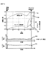
- FIG. 7 is a waveform diagram showing an example of a temporal change in engine start control, in which the engine speed, the energization ratio D output from the control device 109, the battery voltage, and the battery current are associated with temporal changes. Show.
- the energization ratio is calculated using only the engine speed. Since the control device 109 indirectly obtains the motor rotation speed by calculation from the engine rotation speed, the estimation of the motor rotation speed is performed in consideration of the divergence between the estimated motor rotation speed and the actual motor rotation speed. I do.
- a value obtained by converting the motor rotation speed estimated by the control device 109 to the rotation speed on the engine shaft based on the gear ratio between the motor and the engine is indicated by a dotted line 703.
- the battery current 705 at the time of energization is kept almost constant from the start of energization and is kept constant, and is almost the set target current value of the battery current (motor current). Similarly, as shown in FIG.
- the battery voltage 704 at the time of energization is leveled off, and it can be seen that the engine is restarted without falling below the allowable minimum voltage. It is also confirmed that the engine was restarted without falling below the allowable minimum voltage even when the battery deteriorated.
- FIG. 8 is a simple circuit diagram showing the starter 101, the battery 301, and an electric device 803 other than the motor 105 of the starter 101.
- the electric power from the battery 301 is supplied not only to the motor 105 of the starter 101 but also to another electric device 803.
- a method for appropriately changing the motor current flowing through the motor 105 in accordance with the power demand of other electrical equipment other than the motor 105 of the starter 101 will be described.
- the battery current flowing from the battery almost flows into the motor as the motor current.
- the relationship represented by the following equation (8) is established between the total supply current Ie flowing through the device 803.
- the battery current I b is the sum of the supply current I e flowing through the electric devices other than the motor current I m and the motor.
- the battery current I b needs to have a current value that is greater than or equal to the allowable battery current so that the battery voltage V b does not fall below the minimum operating voltage of an electrical component or the like due to a voltage drop of the battery 301.
- the acceptable current value obtained by subtracting the supply current I e from the battery current value motor 105 than other electrical equipment 803, by setting the upper limit value of the motor current I m, is allowed battery current I b in total
- the battery current value is kept constant.
- the supply current I e flowing through the electric device 803 other than the motor 105 is configured to be acquired directly or indirectly.
- the current sensor directly measures the supply current I e flowing through the electric device 803 other than the motor 105, and the control device 109 acquires the measured value from the current sensor.
- Currents normally used by a plurality of electric devices included in other electric devices 803 are individually stored in the control device 109 in advance, and when these electric devices are used, the control device 109 stores the currents.
- the current value of the supply current flowing indirectly through the electric device 803 other than the motor 105 is calculated assuming that the current flows.
- the controller 109 obtains the supply current I e of the other electric devices 803 other than the motor 105 thus, the motor current I m flowing to the motor 105 in order to keep constant the battery current value allowed battery current I b
- the target current value can be calculated.
- the control device 109 calculates the energization ratio D to the motor 105 using the following equation (9).
- the control device 109 acquires the motor rotation speed N m of the motor 105 directly or indirectly.
- the controller 109 may be stored in a controller 109 of the motor rotational speed N m of the motor 105 at the start of the engine model to.
- the controller 109 identifies the appropriate model from among the motor rotation speed N m storage to which the motor 105, selects a motor speed N m corresponding to the identified appropriate model Get by.
- the control device 109 so as to approach the motor current value of the motor current I m to the target current value 409, the motor current I is connected to the motor 105 m controls the switching element 107 to flow.
- a variable resistor may be arranged inside the starter 101 as a circuit element instead of the switching element 107. Controller 109, so as to approach the motor current value of the motor current I m to the target current value 409, to adjust the resistance value of the variable resistor to control the variable resistor is connected to a motor 105 through a motor current I m is.
- the engine starter 100 is an engine starter 101 that starts the engine by transmitting the rotational force of the motor 105 driven by the battery 301 to the engine, and includes a controller 109. .
- the control device 109 acquires the battery voltage V b of the battery 301.
- Controller 109 calculates the target current value 409 of the motor current I m is supplied from the battery 301 to the motor 105.
- Controller 109 so as to approach the motor current value of the motor current I m to the target current value 409, and controls the circuit elements of the switching element 107 or the variable resistor or the like is connected to a motor 105 through a motor current I m is.
- the following effects can be obtained. That is, between the motor energization start until the engine start completion, by maintaining substantially constant for any value of the battery current I b by controlling the motor current I m, it is possible to keep the battery voltage V b is also substantially constant.
- adjustable motor current I m since repeatedly acquires the battery voltage V b to recalculate the target current value in each case the motor current I m, adjustable motor current I m in accordance with a change in the state of the battery 301, such as a sudden voltage drop occurs It is. By doing so, even if the battery state changes, the battery voltage drop remains within the allowable range, and the battery voltage Vb does not fall below the allowable value (minimum operating voltage of electrical components, etc.) when the engine is started. The engine can be started as quickly as possible.
- Controller 109 When the switching element 107 is used as the circuit element, based on the motor rotational speed N m, the controller 109 of the power energization percentage D of the motor 105 by the PWM control is determined. Controller 109, by outputting a PWM control signal for changing the power energization percentage D against the switching element 107 may be a switching element 107, it changes the motor current I m.
- control unit 109 indirectly acquires the rotational speed N m of the motor by calculating from the engine speed N e. In this case, it is not necessary to attach the motor rotation detection sensor 110 for detecting the rotation of the motor 105 to the starter 101, which leads to cost reduction.
- the control device 109 acquires the current I e flowing through another electrical device 803 that uses the same battery 301 as the power source other than the motor 105 so that the battery current I b becomes constant in total.
- the circuit element flowing motor current I m is the voltage drop of the battery 301 even if a large current flows to the other electric devices 803 other than the motor 105 may be suppressed within the allowable range.
Landscapes
- Engineering & Computer Science (AREA)
- Chemical & Material Sciences (AREA)
- Combustion & Propulsion (AREA)
- Mechanical Engineering (AREA)
- General Engineering & Computer Science (AREA)
- Power Engineering (AREA)
- Combined Controls Of Internal Combustion Engines (AREA)
- Control Of Vehicle Engines Or Engines For Specific Uses (AREA)
- Hybrid Electric Vehicles (AREA)
Abstract
バッテリの充電が不十分である場合やバッテリが劣化している場合でも、そのバッテリによって電力が供給される電装品がリセットしない範囲で素早くエンジンを始動させる。 本発明によるエンジン始動装置は、バッテリによって駆動される直流モータの回転力をエンジンへ伝達することによってエンジンを始動させるエンジン始動装置であって、バッテリのバッテリ電圧を取得するバッテリ電圧取得部と、バッテリ電圧取得部によって取得されるバッテリ電圧に基づき、バッテリから直流モータへ供給されるモータ電流の目標電流値を算出する目標電流値算出部と、モータ電流のモータ電流値を目標電流値に近づけるように、直流モータに接続されてモータ電流が流れる回路素子を制御するモータ電流制御部とを備える。
Description
本発明は、車両のエンジン始動装置およびエンジン始動制御方法に関する。
低コスト化の要求を満たしながら、エンジン再始動性を向上させるエンジン自動停止始動制御装置が開示されている(例えば、特許文献1参照)。そのエンジン自動停止始動制御装置においては、スタータモータに比較的大きな電流を通電する必要がないように、スタータモータへの通電をオン/オフするモータ用の機械式リレーとスイッチング素子とが並列に設けられている。エンジン停止位置制御を行う場合には、スイッチング素子によりモータの通電電流が精度良く制御される。
特許文献1に開示されたエンジン自動停止始動制御装置においては、バッテリの充電が不十分である場合、またはバッテリが劣化している場合は、そのバッテリによって電力が供給される電装品がリセットしてしまうことがある。
(1)請求項1に記載のエンジン始動装置は、バッテリによって駆動される直流モータの回転力をエンジンへ伝達することによってエンジンを始動させるエンジン始動装置であって、バッテリのバッテリ電圧を取得するバッテリ電圧取得部と、バッテリ電圧取得部によって取得されるバッテリ電圧に基づき、バッテリから直流モータへ供給されるモータ電流の目標電流値を算出する目標電流値算出部と、モータ電流のモータ電流値を目標電流値に近づけるように、直流モータに接続されてモータ電流が流れる回路素子を制御するモータ電流制御部とを備えることを特徴とする。
(2)請求項8に記載のエンジン始動制御方法は、バッテリによって駆動される直流モータの回転力をエンジンへ伝達することによってエンジンを始動させるエンジン始動を制御するエンジン始動制御方法であって、バッテリのバッテリ電圧を取得し、バッテリ電圧に基づき、バッテリから直流モータへ供給されるモータ電流の目標電流値を算出し、モータ電流のモータ電流値を目標電流値に近づけるように、直流モータに接続されてモータ電流が流れる回路素子を制御することを特徴とする。
(2)請求項8に記載のエンジン始動制御方法は、バッテリによって駆動される直流モータの回転力をエンジンへ伝達することによってエンジンを始動させるエンジン始動を制御するエンジン始動制御方法であって、バッテリのバッテリ電圧を取得し、バッテリ電圧に基づき、バッテリから直流モータへ供給されるモータ電流の目標電流値を算出し、モータ電流のモータ電流値を目標電流値に近づけるように、直流モータに接続されてモータ電流が流れる回路素子を制御することを特徴とする。
本発明によれば、バッテリの充電が不十分である場合やバッテリが劣化している場合でも、そのバッテリによって電力が供給される電装品がリセットしない範囲で素早くエンジンを始動させることができる。
近年の自動車には、エネルギー資源の節約と環境保全を目的として、運転中に所定の条件が成立した時にエンジンを一時停止させるアイドルストップシステムが搭載されている。このアイドルストップシステムにおいては、例えば信号待ちなどで運転者が車両を停止させる際などにエンジンを自動的に停止し、その後、運転者の再始動要求が生じた時点や、エンジンの稼働が必要になった時に自動的にエンジンが再始動する。いわゆるピニオン押し出し式のスタータモータがピニオンを押し出し、ピニオンがエンジン軸と直結されているリングギヤに噛合わさって、スタータモータによるクランキングによってエンジンが始動する。
エンジン始動の際、スタータモータへの通電によりバッテリに電流が流れ、バッテリの特性上、電流に対応して電圧が下がることが知られている。運転中も頻繁にエンジンを停止、再始動させるアイドルストップシステムにおいては、電圧が下がると例えばカーナビゲーションシステムなどの電装品がリセットしてしまうことになる。このため、従来のアイドルストップシステムを搭載している車両においては、補助電源等で対応されているが、搭載性の悪化やコストアップに繋がる。
従来、直流モータを用いて車両のエンジンを始動させるエンジン始動装置として、回路に抵抗を追加することで突入電流を低減し、それによりエンジン始動初期のバッテリ電圧降下を抑制し、その後は抵抗を短絡することで電流を流し、クランキングトルクを確保するエンジン始動装置が知られている。
他の例として、エンジン再始動時にスイッチング素子によってモータへの通電を制御し、PWM制御によりデューティ比を徐々に大きくしてモータの印加電圧を上昇させることで、通電開始直後のバッテリ電圧降下を防止するエンジン始動装置が知られている。
しかしながら、従来のエンジン始動装置では、バッテリ電流が時間と共に低下するように制御されているため、スタータモータの出力トルクが減少し、エンジンのクランキングを十分に行えず、エンジン再始動に時間がかかるおそれがある。また、バッテリの充電が不十分である場合、またはバッテリが劣化している場合においては、許容出来るバッテリ電圧を実際のバッテリ電圧が下回ってしまい、電装品がリセットしてしまうことがある。
本発明によるエンジン始動装置およびエンジン始動制御方法は、バッテリ電圧降下の許容範囲内で最大限に素早くエンジンを再始動させ、なおかつバッテリの状態が変化しても同様にバッテリ電圧効果を許容範囲内に留めることができる。本発明によるエンジン始動装置およびエンジン始動制御方法は、特に、アイドルストップシステムでエンジンを再始動する際に好適である。以下、図1~図8を用いて、本発明の一実施形態によるエンジン始動装置およびエンジン始動制御方法、ならびにそれらの変形例について説明する。
図1は、本発明の一実施形態による車両のエンジン始動装置100およびその関連装置の構成図である。エンジン始動装置100は、スタータ101と、マグネットスイッチ102を通電するためのスイッチ106と、モータ105を通電するためのスイッチング素子107と、制御装置109とを含む。スタータ101は、マグネットスイッチ102と、ピニオンギヤ103と、モータ105とを含む。モータ105は、いわゆる直流モータであり、直流の電圧を付加することで回転駆動力が発生する。ピニオンギヤ103においては、必要な時にマグネットスイッチ102がレバー111を引っ張ることでワンウェイクラッチ108がモータ回転軸上を移動し、エンジン軸と直結されているリングギヤ104と噛み合う。ピニオンギヤ103とリングギヤ104とが噛合った状態であれば、モータ105に通電することでモータ105は回転し、モータ105の回転力はワンウェイクラッチ108を通じてリングギヤ104に伝達され、不図示のエンジンが回る。
制御装置109は、通常の燃料噴射制御、点火制御、空気制御(電子制御スロットル)を行うとともに、ブレーキペダル状態および車速等の各種情報に基づき、アイドルストップを制御する。
モータ回転検知センサ110は、モータ105の回転を検知する。検知されたモータ回転数の情報は、制御装置109に入力される。なお、モータ105の回転をモータ回転検知センサ110で直接検知することに代えて、エンジン回転検知センサ112によって検知されるエンジン回転を使って間接的にモータ105の回転数を検知しても良い。
マグネットスイッチ102は、スイッチ106を介して制御装置109によって制御される。スイッチ106は、例えば機械式リレースイッチである。また、モータ105への通電も、スイッチング素子107を介して制御装置109によってPWM制御される。スイッチング素子107は、例えばMOSFETなどの半導体を用いたスイッチング素子である。
図2は、エンジン始動装置100に含まれるモータ105に対する通電制御に用いられるPWM制御の通電信号の説明図である。制御装置109は、図2に示すPWM信号を通電信号として出力する。そのPWM信号にしたがって、スイッチング素子107がモータ105に対する通電をオン/オフ制御する。
図2において、PWM制御の1周期の長さTは、例えばPWM制御の周波数を10KHzに設定した場合は、0.1msとなる。本実施形態では、モータの電気的時定数よりも十分に早い制御となるようにPWM制御の周波数を決定する。
PWM制御における通電比率Dを、1周期の中での通電する区間の割合と定義する。通電比率Dは、次式(1)のように、1周期の中でモータへ通電する区間TON[s]と、1周期の長さT[s]との比として表される。

通電比率Dは、0.0~1.0の間で値を変化させることができる変数である。制御装置109は、通電比率Dを変えることで、モータへの通電量を制御する。
図3を用いて、本実施形態によるエンジン始動装置100を駆動するための電力を供給するバッテリ301の特性について説明する。図3は、バッテリ301およびスタータ101の簡易的な回路図を示している。一般的に自動車では多くの機器がバッテリによって駆動されるが、ここではバッテリ301およびそのバッテリ301によって駆動されるモータ105を含むスタータ101のみを示している。バッテリ301を流れる電流(バッテリ電流)Ibはモータ105を流れるモータ電流Imと等しい。バッテリ301は内部抵抗Rbを有しているとすると、そのバッテリ301の内部抵抗Rb[Ω]と、バッテリ301の初期電圧(電流が流れていない時の電圧)V0[V]と、バッテリ電流Ib[A]とに基づき、バッテリ301の出力電圧(バッテリ電圧)Vb[V]は、次式(2)によって決まる。

式(2)から分かるように、バッテリ電圧Vbはバッテリ電流Ibによって決められるため、バッテリ電流Ibを所定の値にコントロールできれば、バッテリ電圧Vbも所定の値にコントロールすることができる。バッテリ301の充電が不十分の場合は、バッテリ301の初期電圧V0が十分に充電された状態よりも低くなることがある。また、バッテリ301の経年劣化等により、バッテリ301の内部抵抗Rbが増大し、バッテリ電流Ibが流れている時のバッテリ電圧Vbが低下することがある。バッテリ301の充電が不十分である場合、またはバッテリ301が劣化している場合は、同じバッテリ電流Ibが流れていてもバッテリ電圧Vbが低下し、許容できるバッテリ電圧、例えば電装品がバッテリ301からの電力供給に応じて作動するのに必要な作動電圧を下回ってしまうことが起きる可能性がある。
図4は、モータ電流の後述する目標電流値および上述したPWM制御におけるモータの通電比率の計算方法を示した図である。これらの計算は、制御装置109によって行われる。制御装置109は、不図示のバッテリ電圧検知装置等により検知されたバッテリ電圧Vb、すなわち検知電圧401を、そのバッテリ電圧検知装置等から取得する。図4(a)に示すように、制御装置109は、その取得した検知電圧401と予め設定された目標電圧402とを比較演算403によって比較する。目標電圧402は、電装品などの最低作動電圧などに基づいて予め決定され、制御装置109の内部に記憶させておく。
制御装置109は、検知電圧401と目標電圧402とを比較する際、両者の電圧値の差分を算出する。電圧値の差分に対し、電流換算404では予め決められた定数を用い電流に換算し、その電圧値の差分に比例した電流を基準電流値405に加える。電圧値の差分が負の値であるときは、電圧値の差分に比例した電流を基準電流値405から減らす。このような演算により、スタータ101のモータ105に流すべきバッテリ電流Ibの目標電流値409を決める。つまり、いわゆるフィードバック制御により、バッテリ電圧を目標電圧402に近づけるようにバッテリ301からモータ105へ供給されるバッテリ電流Ibを制御する。電圧の差分に比例して電流を増減させる方式はいわゆる比例制御と呼ばれる。電圧の差分と微分値とに基づいて、または電圧の差分と積分値とに基づいて電流を制御するいわゆるPID制御と呼ばれる手法をとっても良い。
電圧値の差分を電流に換算する際に用いられるその予め決められた定数とは、実験によって定められるフィードバックゲインであり、これを小さくすると収束が遅くなる。電圧値の差分を電流に換算する際、その予め決められた定数を用いる代わりに、予め定められた換算テーブルを用いることとしてもよい。基準電流値405は、電圧値の差分が無いとき、バッテリ301の電圧降下によってバッテリ電圧Vbが電装品などの最低作動電圧を下回ることを防止するように、予め設定される。そのバッテリ301の電圧降下とは、目標電流値409に等しい電流値を示すモータ電流Im(バッテリ電流Ibに対応)がバッテリ301からモータ105へ供給されることに起因して生じる。こうして予め設定された基準電流値405を、制御装置109が記憶する。
電圧値の差分に比例した電流を基準電流値405に加えた場合、バッテリ電流Ibの目標電流値409は大きくなるため、その分、早くエンジンを始動させることが可能である。電圧値の差分に比例した電流を基準電流値405から減らした場合、エンジン始動に時間がかかるものの、電装品などの最低作動電圧以上の大きさのバッテリ電圧Vbを確保することができる。
制御装置109は、モータ回転検知センサ110から、モータ105のモータ回転数を取得する。制御装置109は、こうして取得したモータ回転数と、検知電圧401とに基づき、モータ電流Im(バッテリ電流Ibに対応)の電流値を目標電流値409に近づけるように、スイッチング素子107を制御する。すなわち、図4(b)に示すように、目標電流値409に対して、モータ回転数の情報を用いた通電比率演算407によって出力する通電比率を決定する。通電比率演算407の詳細を、図3を用いて説明する。
図3のモータ部101にて、配線抵抗、モータ内部の内部抵抗、スイッチング素子の抵抗などを含むモータ抵抗Rmと、バッテリ電流Ib(モータ電流Im)[A]と、モータ回転による逆起電圧Ve[V]またはモータ105の逆起電圧係数ke[V/rpm]およびモータ105のモータ回転数Nm[rpm]とを用いて、バッテリ電圧Vb[V]は、次式(3)によって表すことができる。
ここで、式(2)および(3)により、次式(4)が得られる。

式(4)からも分かるように、一般的には直流モータにおいてモータ回転数Nmが0の時、つまり通電し始めの時に電流が一番多く流れ、回転数が大きくなれば電流は少なくなる。
式(4)においては、スイッチング素子107を介した制御装置109によるPWM制御が考慮されていない。すなわち式(4)は、モータ105に対する通電が継続している状態に対応している。本発明の発明者らの研究によると、PWM制御において、通電比率Dに対し電流は次式(5)で近似できることが発見された。式(5)を用いると、PWM制御の通電比率Dを変化させることで電流を一定に制御することができる。
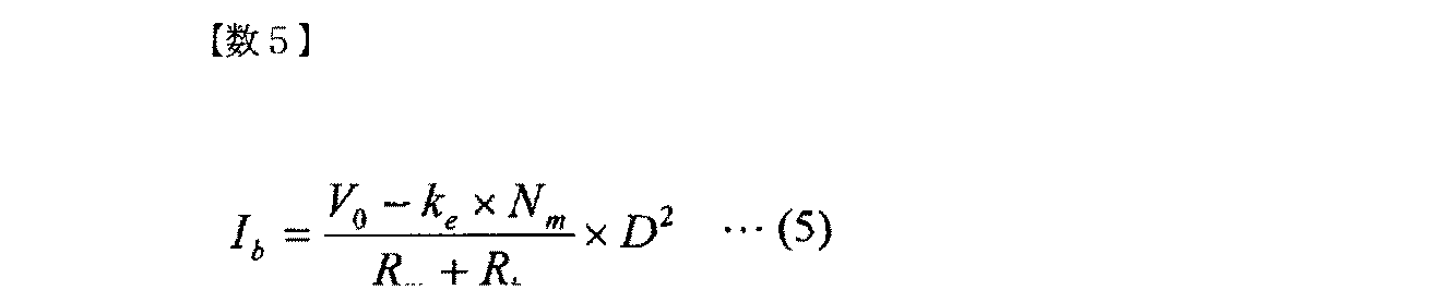
式(5)から分かるように、本実施形態ではPWM制御においてバッテリに流れる電流Ibは通電比率Dの2乗に比例する。図3に示す構成では、スタータ101のモータ105に流れるモータ電流Imは、バッテリ電流Ibに等しいため、モータ電流Imは直流モータ105への通電をPWM制御する際の通電比率Dの2乗に比例すると近似できる。この近似は、本発明の発明者らの研究により実験的に観測したうえで理論的に決定したものである。ただし、式(5)は、PWMの1周期がモータの電気的時定数に対し十分速いと見なせる範囲においてのみ成立する近似であり、バッテリ電流Ibが、定数と、モータ回転数Nmおよび通電比率Dからなる二つの変数とによって決められることを表している。この近似を逆に利用し、所定のバッテリ電流Ibが得られるように通電比率Dを決めるには、式(5)を次式(6)のように変形する。
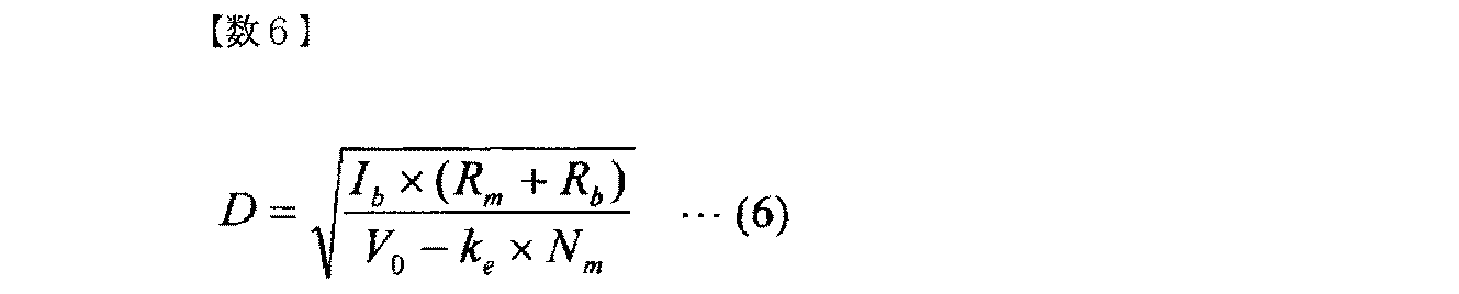
式(6)により、本実施形態では、バッテリ電流Ibを目標電流値409に設定したうえで、モータ回転数Nmにより通電比率Dを決定する。ただし式(6)によって計算された通電比率Dが1.0を超えた場合は通電比率を1.0とする。
図5は、本実施形態によるエンジン始動装置100において制御装置109が行うエンジン始動制御方法の内容を示すフローチャートである。図5に示すように、エンジンの始動要請が発生すると、ステップS510にて、図1に示した制御装置109は、スタータ101と不図示のエンジンとを連結させる。ピニオン押出し方式の場合は、図1のピニオンギヤ103を押し出し、エンジンに直結されているリングギヤ104と噛合わせる。スタータ101とエンジンとが連結状態にあるアイドルストップ方式が適用されている場合、アイドルストップ中においては始動要請が発生した時点で既にスタータ101とエンジンとが連結状態となっている。その場合は、ステップS510における処理は行われる必要がない。
ステップS520において、制御装置109は、予め記憶していたモータ抵抗Rmとモータの逆起電圧係数keとを取得する。ステップS530において、制御装置109は、不図示のバッテリ電圧検知装置等により検知されたバッテリ電圧Vbを取得する。ステップS540において、制御装置109は、電装品などの最低作動電圧に基づいて定められる目標電圧402とバッテリ電圧Vbとの差分を算出する。ステップS550において、制御装置109は、目標電圧402とバッテリ電圧Vbとの差分と、予め記憶していた基準電流値405とに基づき、図4(a)に示す手順で目標電流値409を算出する。ステップS560において、制御装置109は、モータ回転検知センサ110からモータ回転数Nmを取得する。
ステップS570にて、制御装置109は、ステップS520からS560までの各処理ステップで得られた変数および定数を利用し、式(6)にてPWM制御の通電比率Dを計算し、PWM制御の波形信号をスイッチング素子107へ出力し、スイッチング素子107を制御する。制御装置109によるスイッチング素子107に対するPWM制御によりモータ105に電流が流れ始め、モータ105のトルクがエンジンに伝達され、エンジンが回転を始める。
そして、制御装置109は、ステップS580に示すエンジン始動完了条件が成立するまで、ステップ530~S570での処理を継続する。ステップS580のエンジン始動完了条件として、例えばエンジン回転が所定の回転数以上になったこととする。こうした完了条件が満たされると、エンジン始動が完了したと判断することができる。エンジン始動完了までは、制御装置109は、一定間隔(例えば2ms間隔)でバッテリ電圧Vbとモータ回転数Nmとを検知し、通電比率Dを計算し出力を更新する。こうすることでモータ通電開始からエンジン始動完了までの間バッテリ電流はほぼ一定で、設定した電流値となるためバッテリ電圧Vbもほぼ一定となり許容範囲内で、かつ、許容値に近い値に抑えられる。
---変形例---
(1)エンジン始動が完了するまではモータ105の回転力をエンジンに伝達するためにスタータ101とエンジンとは連結状態にあるので、エンジン回転数から間接的にモータ回転数Nmを得ることもできる。
(1)エンジン始動が完了するまではモータ105の回転力をエンジンに伝達するためにスタータ101とエンジンとは連結状態にあるので、エンジン回転数から間接的にモータ回転数Nmを得ることもできる。
図5のステップS510以降、つまりスタータ101のモータ105と不図示のエンジンとが連結状態にあるならば、エンジンのエンジン回転数からモータのモータ回転数Nmを間接的に計算することができる。多くの自動車には、図1に示すように、エンジン回転数を検知するエンジン回転検知センサ112が搭載される。検知されているエンジン回転数から間接的にスタータ101のモータ105の回転数を計算することで、モータ回転検知センサ110を搭載する必要がなくなり、コスト低減に繋がる。エンジン回転数Ne[rpm]と回転数変換係数gとからモータ105のモータ回転数Nm[rpm]を計算する際は、例えば次式(7)を使うことができる。
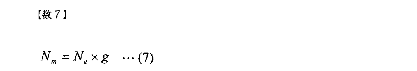
式(7)における回転数変換係数gは、エンジンとモータ105とのギヤ比によって得ることができる。具体的には、ピニオンギヤ103とリングギヤ104とでモータ105とエンジンとが連結されている場合、ピニオンギヤ103およびリングギヤ104のそれぞれの歯数によって決まるギヤ比と、スタータ101内部でモータ105とピニオンギヤ103との間に減速機構が設けられている場合は減速機構の減速比とによって、回転数変換係数gを得ることができる。回転数変換係数gは予め制御装置109に記憶させておき、検知されたエンジン回転数Neを制御装置109内部にてモータ回転数Nmに変換する。
(2)多くのスタータはモータからエンジンへ回転力を伝達する間にワンウェイクラッチを設け、スタータ側からのみ回転力を伝達する構成になっている。エンジンが燃焼を開始しスタータによる回転よりも回転数が大きくなるとクラッチの接続が切れるようになっているため、この時エンジン回転数から計算したスタータ回転数と実際のスタータ回転数とは一致しない。
エンジン回転数から計算して間接的にモータ回転数を取得する場合、計算した値と実際のモータ回転数とに乖離が発生した時のモータ回転数を推測する方法について説明する。多くのスタータ101はモータ105から不図示のエンジンへ回転力を伝達する間にワンウェイクラッチ108が設けられ、スタータ101側からのみ回転力を伝達する構成になっている。つまりモータ105の回転力によってエンジンを回転させることはできるが、エンジンがモータ105を回転させることはないため、実際のモータ回転数よりエンジン回転数から計算して間接的に取得したモータ回転数の方が高い値を示すことがある。その時は、モータ回転数を推測する。
図6は、モータ105の回転数の推測手順を示すフローチャートである。燃焼によりエンジン回転数が跳ね上がった際はクラッチの接続が切れ、ほぼ無負荷の状態となったモータ105は一定の傾きで回転数が上がると仮定する。そのような仮定のうえで、間接的に取得したモータ回転数Nmに対し、制御周期毎の回転数の上昇に上限を設けることでエンジン回転の急上昇に対しモータ回転数を推測する。
エンジン回転検知センサ112が検知したエンジン回転数Neに基づいて間接的に取得されたモータの回転数Nmに対し、そのモータの回転数Nmが実際のモータ回転数から乖離している可能性を考慮して推測された推測モータ回転数Nm_outを使い、通電比率Dを計算する。これを制御周期毎に繰り返し、1制御周期前の計算結果をNm_outt-1として制御装置内で記憶しておく。また、制御周期毎のモータ回転数の上昇の上限として上限値ΔNを予め設定しておく。
ステップS610にて、図1の制御装置109は、推測モータ回転数Nm_outt-1に上限値ΔNを加えて新たに推測した推測モータ回転数をNm´とする。新たに推測した推測モータ回転数Nm´は、1周期前の推測モータ回転数Nm_outt-1に対し1制御周期内で上昇し得る最大の値と考えられる。
ステップS620にて、制御装置109は、間接的に取得したモータ回転数Nmと推測モータ回転数Nm´とを比較し、実際のモータ回転数からの乖離が発生しているかどうかを判定する。ステップS620にて、制御装置109は、Nm≧Nm´を否定判定した場合は、間接的に取得したモータ回転数と実際のモータ回転数との間に乖離はないと判断する。ステップS640にて、制御装置109は、間接的に取得したモータ回転数Nmをそのまま推測モータ回転数Nm_outに代入し、推測モータ回転数Nm_outを通電比率Dの計算に使う。
ステップS620にて、制御装置109は、Nm≧Nm´を肯定判定した場合は、間接的に取得したモータ回転数と実際のモータ回転数との間に乖離があると判断する。その場合はステップS630にて、制御装置109は、推測モータ回転数Nm´を推測モータ回転数Nm_outに代入し、推測モータ回転数Nm_outを通電比率Dの計算に使う。こうすることで、エンジン回転数から計算して間接的にモータ回転数を求めた場合に実際のモータ回転数から乖離が発生しても正しく通電比率Dを計算することができる。
図7は、エンジン始動制御の時間的変化の一例を示す波形図であり、エンジン回転数、制御装置109から出力された通電比率D、バッテリ電圧、およびバッテリ電流の時間的変化を、対応付けて示している。
図7に示す例では、エンジン回転数のみを用いて通電比率を計算している。制御装置109は、エンジン回転数から計算によって間接的にモータ回転数を取得しているため、推測したモータ回転数と実際のモータ回転数との間の乖離を考慮してモータの回転数の推測を行う。このように制御装置109が推測したモータ回転数をモータとエンジンとのギヤ比に基づいてエンジン軸上の回転数に換算した値を、点線703で示す。通電時のバッテリ電流705は、図7に示すように通電開始からほぼ横ばいで一定に保たれており、ほぼ設定したバッテリ電流(モータ電流)の目標電流値になっている。通電時のバッテリ電圧704も同様に、図7に示すように横ばいで許容最低電圧を下回ることなくエンジンを再始動させたことがわかる。バッテリが劣化した場合でも同様に許容最低電圧を下回ることなくエンジンを再始動させたことも確認している。
(3)通電比率Dの他の決定方法について説明する。図8は、スタータ101と、バッテリ301と、スタータ101のモータ105以外の他の電気機器803とを表す簡易的な回路図である。バッテリ301からの電力は、スタータ101のモータ105だけでなく、他の電気機器803にも供給される。スタータ101のモータ105以外の他の電気機器の電力需要に合わせてモータ105に流すモータ電流を適宜変更する方法について説明する。図3の簡易的な回路図において、バッテリから流れるバッテリ電流は、ほとんどモータ電流としてモータに流れる。しかし、実際の車両では、スタータ101のモータ105以外にも電流が流れる他の電気機器803が存在する。
バッテリ301を流れるバッテリ電流Ibと、バッテリ301からスタータ101のモータ105に供給されてモータ105を流れる電流Imと、バッテリ301からモータ105以外の他の電気機器803に供給されて他の電気機器803を流れる合計の供給電流Ieとの間には、次式(8)に示す関係が成り立つ。
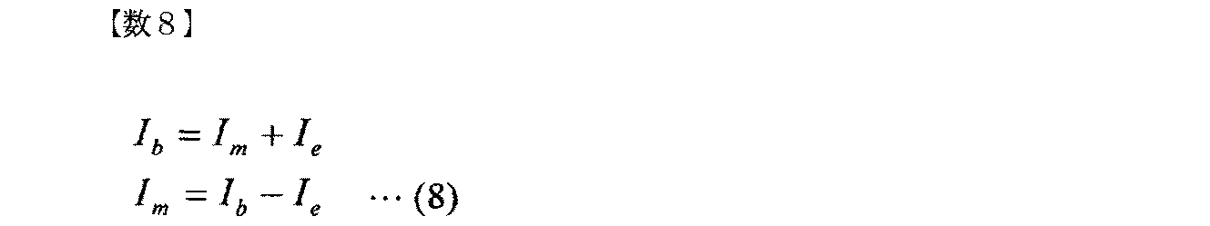
式(8)に示すように、バッテリ電流Ibはモータ電流Imとモータ以外の電気機器を流れる供給電流Ieとの和である。バッテリ電流Ibは、バッテリ301の電圧降下によってバッテリ電圧Vbが電装品などの最低作動電圧を下回ることとならないように、許容されるバッテリ電流以上の電流値を有する必要がある。許容されるバッテリ電流値からモータ105以外の他の電気機器803の供給電流Ieを差し引いた電流値を、モータ電流Imの上限値として設定することで、トータルとしてバッテリ電流Ibを許容されるバッ
テリ電流値に一定に保つ構成にする。モータ105以外の他の電気機器803を流れる供給電流Ieは、直接的または間接的に取得され得る構成にする。例えば、モータ105以外の他の電気機器803を流れる供給電流Ieを電流センサが直接計測し、その計測値を制御装置109が電流センサから取得する。他の電気機器803に含まれる複数の電気機器が通常使用する電流を個々に予め制御装置109に記憶させておき、それらの電気機器が使用されている場合には、制御装置109が、記憶しておいた電流が流れるものとして、間接的にモータ105以外の他の電気機器803を流れる供給電流の電流値を算出する。こうして制御装置109がモータ105以外の他の電気機器803の供給電流Ieを取得することによって、バッテリ電流Ibを許容されるバッテリ電流値に一定に保つためにモータ105へ流すモータ電流Imの目標電流値を算出することができる。制御装置109は、次式(9)を用いてモータ105への通電比率Dを計算する。

テリ電流値に一定に保つ構成にする。モータ105以外の他の電気機器803を流れる供給電流Ieは、直接的または間接的に取得され得る構成にする。例えば、モータ105以外の他の電気機器803を流れる供給電流Ieを電流センサが直接計測し、その計測値を制御装置109が電流センサから取得する。他の電気機器803に含まれる複数の電気機器が通常使用する電流を個々に予め制御装置109に記憶させておき、それらの電気機器が使用されている場合には、制御装置109が、記憶しておいた電流が流れるものとして、間接的にモータ105以外の他の電気機器803を流れる供給電流の電流値を算出する。こうして制御装置109がモータ105以外の他の電気機器803の供給電流Ieを取得することによって、バッテリ電流Ibを許容されるバッテリ電流値に一定に保つためにモータ105へ流すモータ電流Imの目標電流値を算出することができる。制御装置109は、次式(9)を用いてモータ105への通電比率Dを計算する。
モータ105以外の他の電気機器803を流れる供給電流Ieが変化しても、式(8)を用いてモータ105に流れるモータ電流Imの目標電流値を決定し、モータ105への通電比率Dを式(9)を用いて計算することで、バッテリ電流Ibを一定に保つことができる。したがって、バッテリ301の電圧降下を許容範囲に抑えながら最大限にエンジンを素早く再始動させることができる。
(4)上述した実施形態またはその変形例によるエンジン始動装置100において、制御装置109は、モータ105のモータ回転数Nmを、直接的に、または間接的に取得する。しかし、エンジン始動装置100の製造時に、エンジン始動時のモータ105のモータ回転数Nmをモデル化して制御装置109に記憶させておくこととしてもよい。実際のエンジン始動時には、制御装置109は、適切なモデルを特定し、記憶しているモータ105のモータ回転数Nmのうちから、その特定した適切なモデルに対応するモータ回転数Nmを選択することによって取得する。
(5)上述した実施形態またはその変形例によるエンジン始動装置100において、制御装置109は、モータ電流Imのモータ電流値を目標電流値409に近づけるように、モータ105に接続されてモータ電流Imが流れるスイッチング素子107を制御する。しかし、スイッチング素子107の代わりの回路素子として、スタータ101の内部に可変抵抗を配置することとしてもよい。制御装置109は、モータ電流Imのモータ電流値を目標電流値409に近づけるように、モータ105に接続されてモータ電流Imが流れる可変抵抗を制御して可変抵抗の抵抗値を調節する。
上述した実施形態またはその変形例によるエンジン始動装置100は、バッテリ301によって駆動されるモータ105の回転力をエンジンへ伝達することによってエンジンを始動させるエンジン始動装置101であって、制御装置109を有する。制御装置109は、バッテリ301のバッテリ電圧Vbを取得する。制御装置109は、取得したバッテリ電圧Vbに基づき、バッテリ301からモータ105へ供給されるモータ電流Imの目標電流値409を算出する。制御装置109は、モータ電流Imのモータ電流値を目標電流値409に近づけるように、モータ105に接続されてモータ電流Imが流れるスイッチング素子107または可変抵抗等の回路素子を制御する。このようなエンジン始動装置100においては、次のような効果が得られる。すなわち、モータ通電開始からエンジン始動完了までの間、モータ電流Imを制御してバッテリ電流Ibをほぼ一定の任意の値に保つことで、バッテリ電圧Vbもほぼ一定に保つことができる。特に、バッテリ電圧Vbを繰り返し取得してそのつどモータ電流Imの目標電流値を再計算するので、急な電圧降下が生じるなどのバッテリ301の状態変化に応じてモータ電流Imを調節可能である。そうすることで、バッテリの状態が変化してもバッテリ電圧降下を許容範囲内に留め、エンジン始動時にバッテリ電圧Vbが許容値(電装品などの最低作動電圧)を下回ることなく、その状態でなおかつ最大限にすばやくエンジンを始動させることができる。
上記回路素子としてスイッチング素子107が用いられる場合は、モータ回転数Nmをもとに、PWM制御によるモータ105への通電比率Dを制御装置109が決定する。制御装置109が、その通電比率Dを変化させるPWM制御信号をスイッチング素子107に対して出力することによって、スイッチング素子107が、モータ電流Imを変化させることができる。
変形例(1)および(2)においては、制御装置109が、エンジン回転数Neから計算によって間接的にモータの回転数Nmを取得する。この場合、スタータ101にモータ105の回転検出用のモータ回転検知センサ110を取り付ける必要がないため、コスト低減に繋がる。
変形例(3)においては、制御装置109が、モータ105以外で同じバッテリ301を電源とする他の電気機器803に流れる電流Ieを取得し、バッテリ電流Ibをトータルで一定になるようにモータ電流Imが流れる回路素子を制御する場合は、モータ105以外の他の電気機器803に大きな電流が流れてもバッテリ301の電圧降下を許容範囲内に抑えることができる。
100…エンジン始動装置
101…スタータ
102…マグネットスイッチ
103…ピニオンギヤ
104…リングギヤ
105…モータ
106…スイッチ
107…スイッチング素子
108…ワンウェイクラッチ
109…制御装置
110…モータ回転検知センサ
111…レバー
112…エンジン回転検知センサ
301…バッテリ
101…スタータ
102…マグネットスイッチ
103…ピニオンギヤ
104…リングギヤ
105…モータ
106…スイッチ
107…スイッチング素子
108…ワンウェイクラッチ
109…制御装置
110…モータ回転検知センサ
111…レバー
112…エンジン回転検知センサ
301…バッテリ
Claims (9)
- バッテリによって駆動される直流モータの回転力をエンジンへ伝達することによって前記エンジンを始動させるエンジン始動装置であって、
前記バッテリのバッテリ電圧を取得するバッテリ電圧取得部と、
前記バッテリ電圧取得部によって取得される前記バッテリ電圧に基づき、前記バッテリから前記直流モータへ供給されるモータ電流の目標電流値を算出する目標電流値算出部と、
前記モータ電流のモータ電流値を前記目標電流値に近づけるように、前記直流モータに接続されて前記モータ電流が流れる回路素子を制御するモータ電流制御部とを備えることを特徴とするエンジン始動装置。 - 請求項1に記載のエンジン始動装置において、
前記直流モータのモータ回転数を取得するモータ回転数取得部をさらに備え、
前記モータ電流制御部は、前記モータ電流値を前記目標電流値に近づけるように、前記バッテリ電圧取得部によって取得される前記バッテリ電圧と、前記モータ回転数取得部によって取得される前記モータ回転数とに基づき、前記回路素子を制御することを特徴とするエンジン始動装置。 - 請求項2に記載のエンジン始動装置において、
前記モータ電流制御部は、前記直流モータ以外の他の電気機器が前記バッテリからの電力供給に応じて作動するのに必要な作動電圧に基づいて定められる目標電圧と、前記目標電流値の基準電流値とを記憶し、
前記目標電流値算出部は、前記バッテリ電圧取得部によって取得される前記バッテリ電圧と前記目標電圧との電圧差分と、前記モータ電流制御部によって記憶される前記基準電流値とに基づいて、前記目標電流値を算出し、
前記モータ電流制御部によって記憶される前記基準電流値は、前記電圧差分が無いとき、前記目標電流値に等しい電流値を示す前記モータ電流が前記バッテリから前記直流モータへ供給されることに起因して生じる前記バッテリの電圧降下によって前記バッテリ電圧が前記作動電圧を下回ることを防止するように、予め設定されることを特徴とするエンジン始動装置。 - 請求項2または3に記載のエンジン始動装置において、
前記モータ電流制御部は、前記バッテリから前記直流モータへの通電の開始および停止を繰り返すPWM制御を、前記通電の前記開始から前記停止に至るまでの時間と前記通電の前記開始から前記停止を経て再び前記開始に至るまでの時間との比で表される通電比率に応じて前記回路素子を制御することによって行い、
前記モータ電流制御部は、前記バッテリ電圧取得部によって取得される前記バッテリ電圧と、前記バッテリの内部抵抗と、前記目標電流値算出部によって算出される前記目標電流値と、前記モータ回転数取得部によって取得される前記モータ回転数と、前記直流モータが有するモータ抵抗と、前記直流モータの逆起電圧係数とに基づいて、前記通電比率を決定することを特徴とするエンジン始動装置。 - 請求項4に記載のエンジン始動装置において、
前記モータ回転数取得部は、前記モータ回転数を検知するモータ回転検知部から前記モータ回転数を取得することを特徴とするエンジン始動装置。 - 請求項4に記載のエンジン始動装置において、
前記モータ回転数取得部は、前記エンジンのエンジン回転数を取得し、前記エンジン回転数に基づき、前記モータ回転数を取得することを特徴とするエンジン始動装置。 - 請求項3に記載のエンジン始動装置において、
前記バッテリから前記他の電気機器へ供給される供給電流を取得する供給電流取得部をさらに備え、
前記目標電流値算出部は、前記バッテリ電圧取得部によって取得される前記バッテリ電圧と前記目標電圧との前記電圧差分と、前記モータ電流制御部によって記憶される前記基準電流値と、前記供給電流取得部によって取得される前記供給電流とに基づいて、前記目標電流値を算出することを特徴とするエンジン始動装置。 - バッテリによって駆動される直流モータの回転力をエンジンへ伝達することによって前記エンジンを始動させるエンジン始動を制御するエンジン始動制御方法であって、
前記バッテリのバッテリ電圧を取得し、
前記バッテリ電圧に基づき、前記バッテリから前記直流モータへ供給されるモータ電流の目標電流値を算出し、
前記モータ電流のモータ電流値を前記目標電流値に近づけるように、前記直流モータに接続されて前記モータ電流が流れる回路素子を制御することを特徴とするエンジン始動制御方法。 - 請求項8に記載のエンジン始動制御方法において、さらに、
前記目標電流値が算出される際には、前記直流モータ以外の他の電気機器が前記バッテリからの電力供給に応じて作動するのに必要な作動電圧に基づいて定められる目標電圧と前記バッテリ電圧との電圧差分と、前記目標電流値の基準電流値とに基づいて、前記目標電流値を算出し、
前記基準電流値は、前記電圧差分が無いとき、前記目標電流値に等しい電流値を示す前記モータ電流が前記バッテリから前記直流モータへ供給されることに起因して生じる前記バッテリの電圧降下によって前記バッテリ電圧が前記作動電圧を下回ることを防止するように、予め設定され、
前記直流モータのモータ回転数を取得し、
前記モータ電流値を前記目標電流値に近づけるように前記回路素子が制御される際には、前記バッテリ電圧と前記モータ回転数とに基づき、前記回路素子を制御することを特徴とするエンジン始動制御方法。
Priority Applications (3)
| Application Number | Priority Date | Filing Date | Title |
|---|---|---|---|
| CN201480033606.3A CN105308307B (zh) | 2013-06-14 | 2014-05-16 | 引擎启动装置以及引擎启动控制方法 |
| EP14810127.2A EP3009667A4 (en) | 2013-06-14 | 2014-05-16 | Engine start-up device, and engine-start-up control method |
| US14/897,853 US9765745B2 (en) | 2013-06-14 | 2014-05-16 | Engine start-up device, and engine-start-up control method |
Applications Claiming Priority (2)
| Application Number | Priority Date | Filing Date | Title |
|---|---|---|---|
| JP2013125867A JP6062324B2 (ja) | 2013-06-14 | 2013-06-14 | エンジン始動装置およびエンジン始動制御方法 |
| JP2013-125867 | 2013-06-14 |
Publications (1)
| Publication Number | Publication Date |
|---|---|
| WO2014199772A1 true WO2014199772A1 (ja) | 2014-12-18 |
Family
ID=52022073
Family Applications (1)
| Application Number | Title | Priority Date | Filing Date |
|---|---|---|---|
| PCT/JP2014/063009 Ceased WO2014199772A1 (ja) | 2013-06-14 | 2014-05-16 | エンジン始動装置およびエンジン始動制御方法 |
Country Status (5)
| Country | Link |
|---|---|
| US (1) | US9765745B2 (ja) |
| EP (1) | EP3009667A4 (ja) |
| JP (1) | JP6062324B2 (ja) |
| CN (1) | CN105308307B (ja) |
| WO (1) | WO2014199772A1 (ja) |
Families Citing this family (7)
| Publication number | Priority date | Publication date | Assignee | Title |
|---|---|---|---|---|
| CN103946604B (zh) * | 2011-11-17 | 2016-03-16 | 丰田自动车株式会社 | 车辆用发动机起动装置 |
| JP6948844B2 (ja) * | 2017-06-06 | 2021-10-13 | 日立Astemo株式会社 | エンジンの始動装置 |
| JP7408395B2 (ja) * | 2017-11-22 | 2024-01-05 | 株式会社Gsユアサ | 再始動判定装置、内部ショート判定装置、再始動判定方法、及びコンピュータプログラム |
| JP7010044B2 (ja) * | 2018-02-13 | 2022-01-26 | トヨタ自動車株式会社 | 車両のエンジン始動制御装置 |
| JP7189421B2 (ja) * | 2018-09-21 | 2022-12-14 | ミツミ電機株式会社 | モータ駆動回路及びモータ駆動装置 |
| US12562667B2 (en) | 2020-05-06 | 2026-02-24 | Safran Power Usa, Llc | Starter-generator control unit (SGCU) randomized current feedback control |
| WO2021225589A1 (en) * | 2020-05-06 | 2021-11-11 | Innovative Power Solutions, Llc | Starter-generator speed control |
Citations (4)
| Publication number | Priority date | Publication date | Assignee | Title |
|---|---|---|---|---|
| JP2004308645A (ja) * | 2003-03-25 | 2004-11-04 | Denso Corp | エンジン始動装置 |
| JP2005188451A (ja) * | 2003-12-26 | 2005-07-14 | Nippon Soken Inc | エンジン始動制御装置 |
| JP2010106825A (ja) | 2008-10-04 | 2010-05-13 | Denso Corp | エンジン自動停止始動制御装置 |
| WO2013080746A1 (ja) * | 2011-11-29 | 2013-06-06 | 日立オートモティブシステムズ株式会社 | エンジン始動装置および始動方法 |
Family Cites Families (28)
| Publication number | Priority date | Publication date | Assignee | Title |
|---|---|---|---|---|
| JP3746334B2 (ja) * | 1996-08-22 | 2006-02-15 | トヨタ自動車株式会社 | 永久磁石型同期モータの駆動制御装置及び方法 |
| CN1190886C (zh) * | 2000-02-28 | 2005-02-23 | 株式会社安川电机 | 脉冲宽度调制的脉冲控制方法 |
| DE10056970A1 (de) * | 2000-11-17 | 2002-05-23 | Bosch Gmbh Robert | Verfahren und Anordnung zur Ermittlung der Startfähigkeit einer Starterbatterie eines Verbrennungsmotors |
| JP2002327668A (ja) * | 2001-04-27 | 2002-11-15 | Toyota Motor Corp | 車両の電池電力配分制御装置 |
| DE102004007393A1 (de) | 2003-02-28 | 2004-09-09 | Denso Corp., Kariya | Maschinenanlasser mit einem Anlassermotor |
| JP4490173B2 (ja) * | 2004-05-31 | 2010-06-23 | 本田技研工業株式会社 | 車両用内燃機関の始動制御装置 |
| JP4622872B2 (ja) * | 2006-01-26 | 2011-02-02 | トヨタ自動車株式会社 | 車両の電源装置、車両および車両の電源装置の制御方法 |
| JP4064428B2 (ja) * | 2006-05-24 | 2008-03-19 | 本田技研工業株式会社 | 内燃機関の制御装置 |
| JP4978429B2 (ja) * | 2007-11-01 | 2012-07-18 | アイシン・エィ・ダブリュ株式会社 | 電動機制御装置,電気自動車およびハイブリッド電気自動車 |
| JP5018516B2 (ja) * | 2008-01-31 | 2012-09-05 | アイシン・エィ・ダブリュ株式会社 | 回転電機制御装置 |
| JP5286981B2 (ja) * | 2008-07-03 | 2013-09-11 | 株式会社ジェイテクト | 電動パワーステアリング装置 |
| JP5195923B2 (ja) * | 2008-12-24 | 2013-05-15 | アイシン・エィ・ダブリュ株式会社 | ハイブリッド駆動装置 |
| JP5165669B2 (ja) * | 2009-12-03 | 2013-03-21 | 日立オートモティブシステムズ株式会社 | エンジン始動装置 |
| JP5482521B2 (ja) * | 2010-02-10 | 2014-05-07 | 株式会社デンソー | スタータ制御装置 |
| JP2011190734A (ja) * | 2010-03-15 | 2011-09-29 | Fujitsu Ten Ltd | アイドリングストップ装置、及び、エンジン始動方法 |
| JP5073007B2 (ja) * | 2010-04-28 | 2012-11-14 | 三菱電機株式会社 | エンジン自動停止再始動装置 |
| JP5454685B2 (ja) * | 2010-06-25 | 2014-03-26 | トヨタ自動車株式会社 | モータ駆動装置およびそれを搭載する車両 |
| JP5450311B2 (ja) * | 2010-08-04 | 2014-03-26 | 日立オートモティブシステムズ株式会社 | アイドルストップ制御方法および制御装置 |
| JP5470241B2 (ja) * | 2010-12-28 | 2014-04-16 | 日立オートモティブシステムズ株式会社 | 車両の制御装置 |
| JP5628714B2 (ja) * | 2011-03-11 | 2014-11-19 | 日立オートモティブシステムズ株式会社 | 車両用エンジン始動装置 |
| JP5276697B2 (ja) * | 2011-06-15 | 2013-08-28 | 三菱電機株式会社 | 車載エンジンの始動制御装置 |
| JP5413420B2 (ja) * | 2011-08-08 | 2014-02-12 | 株式会社デンソー | 回転機の制御装置 |
| JP2013151862A (ja) * | 2012-01-24 | 2013-08-08 | Hitachi Koki Co Ltd | エンジン作業機 |
| JP2013194542A (ja) * | 2012-03-16 | 2013-09-30 | Nissan Motor Co Ltd | エンジン始動装置 |
| JP2013209900A (ja) * | 2012-03-30 | 2013-10-10 | Hitachi Automotive Systems Ltd | エンジン始動装置 |
| JP5947705B2 (ja) * | 2012-12-12 | 2016-07-06 | トヨタ自動車株式会社 | 交流電動機の制御システム |
| JP5874688B2 (ja) * | 2013-06-05 | 2016-03-02 | 株式会社デンソー | 制御装置 |
| JP5865930B2 (ja) * | 2014-03-07 | 2016-02-17 | 三菱電機株式会社 | モータ制御装置 |
-
2013
- 2013-06-14 JP JP2013125867A patent/JP6062324B2/ja not_active Expired - Fee Related
-
2014
- 2014-05-16 WO PCT/JP2014/063009 patent/WO2014199772A1/ja not_active Ceased
- 2014-05-16 CN CN201480033606.3A patent/CN105308307B/zh not_active Expired - Fee Related
- 2014-05-16 US US14/897,853 patent/US9765745B2/en not_active Expired - Fee Related
- 2014-05-16 EP EP14810127.2A patent/EP3009667A4/en not_active Withdrawn
Patent Citations (4)
| Publication number | Priority date | Publication date | Assignee | Title |
|---|---|---|---|---|
| JP2004308645A (ja) * | 2003-03-25 | 2004-11-04 | Denso Corp | エンジン始動装置 |
| JP2005188451A (ja) * | 2003-12-26 | 2005-07-14 | Nippon Soken Inc | エンジン始動制御装置 |
| JP2010106825A (ja) | 2008-10-04 | 2010-05-13 | Denso Corp | エンジン自動停止始動制御装置 |
| WO2013080746A1 (ja) * | 2011-11-29 | 2013-06-06 | 日立オートモティブシステムズ株式会社 | エンジン始動装置および始動方法 |
Non-Patent Citations (1)
| Title |
|---|
| See also references of EP3009667A4 * |
Also Published As
| Publication number | Publication date |
|---|---|
| US20160138549A1 (en) | 2016-05-19 |
| US9765745B2 (en) | 2017-09-19 |
| CN105308307A (zh) | 2016-02-03 |
| CN105308307B (zh) | 2017-10-31 |
| EP3009667A1 (en) | 2016-04-20 |
| EP3009667A4 (en) | 2017-09-20 |
| JP6062324B2 (ja) | 2017-01-18 |
| JP2015001187A (ja) | 2015-01-05 |
Similar Documents
| Publication | Publication Date | Title |
|---|---|---|
| JP6062324B2 (ja) | エンジン始動装置およびエンジン始動制御方法 | |
| US10782353B2 (en) | Lithium ion battery residual capacity estimation device | |
| JP2010230654A (ja) | バッテリの状態検出装置 | |
| US8773136B2 (en) | Method for evaluating the ability of a battery to start | |
| US8862365B2 (en) | Vehicular power supply device | |
| JP2004308645A (ja) | エンジン始動装置 | |
| CN102251900B (zh) | 发动机起动装置 | |
| US20140132002A1 (en) | Vehicle power source device | |
| KR102417347B1 (ko) | 마일드 하이브리드 차량의 엔진 시동 방법 및 장치 | |
| JP5761717B2 (ja) | エンジン始動装置および始動方法 | |
| CN105717454B (zh) | 电池监测装置 | |
| US8549939B2 (en) | Start control device | |
| JP4799641B2 (ja) | エンジン始動装置 | |
| JP4869395B2 (ja) | エンジン始動装置 | |
| JP6515786B2 (ja) | エンジンの始動制御装置 | |
| JP5353422B2 (ja) | 車両用発電制御装置 | |
| JP2012228017A (ja) | 発電電動機の制御装置 | |
| JP5282704B2 (ja) | 車両制御装置及び車両制御方法 | |
| JP6667960B2 (ja) | 車両用制御装置 | |
| JP2006180665A (ja) | ハイブリッド車両の充電装置 | |
| CN103154499B (zh) | 用于起动内燃机的方法和装置以及换接装置 | |
| JP7225720B2 (ja) | 回転電機の発電トルク制御装置 | |
| CN107813779B (zh) | 车辆用电源装置 | |
| JP6851743B2 (ja) | ジャンピングスタート判定装置 | |
| JP5903328B2 (ja) | エンジン始動装置 |
Legal Events
| Date | Code | Title | Description |
|---|---|---|---|
| WWE | Wipo information: entry into national phase |
Ref document number: 201480033606.3 Country of ref document: CN |
|
| 121 | Ep: the epo has been informed by wipo that ep was designated in this application |
Ref document number: 14810127 Country of ref document: EP Kind code of ref document: A1 |
|
| WWE | Wipo information: entry into national phase |
Ref document number: 14897853 Country of ref document: US |
|
| NENP | Non-entry into the national phase |
Ref country code: DE |
|
| WWE | Wipo information: entry into national phase |
Ref document number: 2014810127 Country of ref document: EP |