WO2014199814A1 - 無線基地局、無線通信システムおよび無線通信方法 - Google Patents
無線基地局、無線通信システムおよび無線通信方法 Download PDFInfo
- Publication number
- WO2014199814A1 WO2014199814A1 PCT/JP2014/063895 JP2014063895W WO2014199814A1 WO 2014199814 A1 WO2014199814 A1 WO 2014199814A1 JP 2014063895 W JP2014063895 W JP 2014063895W WO 2014199814 A1 WO2014199814 A1 WO 2014199814A1
- Authority
- WO
- WIPO (PCT)
- Prior art keywords
- base station
- radio base
- interference
- subframe
- inter
- Prior art date
- Legal status (The legal status is an assumption and is not a legal conclusion. Google has not performed a legal analysis and makes no representation as to the accuracy of the status listed.)
- Ceased
Links
Images


Classifications
-
- H—ELECTRICITY
- H04—ELECTRIC COMMUNICATION TECHNIQUE
- H04W—WIRELESS COMMUNICATION NETWORKS
- H04W72/00—Local resource management
- H04W72/50—Allocation or scheduling criteria for wireless resources
- H04W72/54—Allocation or scheduling criteria for wireless resources based on quality criteria
- H04W72/541—Allocation or scheduling criteria for wireless resources based on quality criteria using the level of interference
-
- H—ELECTRICITY
- H04—ELECTRIC COMMUNICATION TECHNIQUE
- H04L—TRANSMISSION OF DIGITAL INFORMATION, e.g. TELEGRAPHIC COMMUNICATION
- H04L1/00—Arrangements for detecting or preventing errors in the information received
-
- H—ELECTRICITY
- H04—ELECTRIC COMMUNICATION TECHNIQUE
- H04L—TRANSMISSION OF DIGITAL INFORMATION, e.g. TELEGRAPHIC COMMUNICATION
- H04L5/00—Arrangements affording multiple use of the transmission path
- H04L5/14—Two-way operation using the same type of signal, i.e. duplex
-
- H—ELECTRICITY
- H04—ELECTRIC COMMUNICATION TECHNIQUE
- H04L—TRANSMISSION OF DIGITAL INFORMATION, e.g. TELEGRAPHIC COMMUNICATION
- H04L5/00—Arrangements affording multiple use of the transmission path
- H04L5/22—Arrangements affording multiple use of the transmission path using time-division multiplexing
-
- H—ELECTRICITY
- H04—ELECTRIC COMMUNICATION TECHNIQUE
- H04W—WIRELESS COMMUNICATION NETWORKS
- H04W16/00—Network planning, e.g. coverage or traffic planning tools; Network deployment, e.g. resource partitioning or cells structures
- H04W16/02—Resource partitioning among network components, e.g. reuse partitioning
-
- H—ELECTRICITY
- H04—ELECTRIC COMMUNICATION TECHNIQUE
- H04W—WIRELESS COMMUNICATION NETWORKS
- H04W72/00—Local resource management
- H04W72/04—Wireless resource allocation
- H04W72/044—Wireless resource allocation based on the type of the allocated resource
- H04W72/0446—Resources in time domain, e.g. slots or frames
-
- H—ELECTRICITY
- H04—ELECTRIC COMMUNICATION TECHNIQUE
- H04W—WIRELESS COMMUNICATION NETWORKS
- H04W72/00—Local resource management
- H04W72/20—Control channels or signalling for resource management
-
- H—ELECTRICITY
- H04—ELECTRIC COMMUNICATION TECHNIQUE
- H04W—WIRELESS COMMUNICATION NETWORKS
- H04W92/00—Interfaces specially adapted for wireless communication networks
- H04W92/16—Interfaces between hierarchically similar devices
- H04W92/20—Interfaces between hierarchically similar devices between access points
Definitions
- the present invention relates to a radio base station, a radio communication system, and a radio communication method applicable to a radio communication system using time division duplex (TDD).
- TDD time division duplex
- FDD frequency division duplex
- UL UpLink
- DL DownLink
- TDD Time Division Duplex
- a UL / DL configuration (UL / DL configuration) is defined as a frame configuration indicating a configuration ratio of an uplink subframe and a downlink subframe in a radio frame (See FIG. 1).
- seven frame configurations are defined as UL / DL configurations.
- UL traffic and DL traffic are asymmetric. Further, the ratio of UL traffic to DL traffic is not constant, but varies with time or location. For this reason, in a wireless communication system using TDD, from the viewpoint of effective use of radio resources, the UL / DL configuration shown in FIG. 1 is not fixed, but is temporally adjusted according to actual traffic fluctuations. Alternatively, it is desirable to change the location.
- the present invention has been made in view of such a point, and while effectively avoiding interference, a radio base station, a radio communication system, and radio communication capable of controlling the amount of radio resources that are not used to avoid interference It aims to provide a method.
- the radio base station of the present invention is a radio base station connected to an adjacent radio base station via an interface between radio base stations, and is a UL / DL indicating the configuration of uplink subframes and downlink subframes in a radio frame.
- a radio communication unit that performs radio communication with a user terminal using a configuration, an interference recognition unit that measures and detects interference received by the radio base station, and inter-cell orthogonality to each subframe based on the interference detection result And a selection unit that selects whether to apply the restricted frequency domain radio resource allocation method.
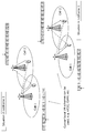
- radio communication is performed by TDD between the radio base station and the user terminal in the cell 1 and between the radio base station and the user terminal in the cell 2.
- the UL / DL configuration 0 with a lot of UL traffic is applied.
- the UL / DL configuration 5 having a lot of DL traffic is applied.
- the radio base station in cell 1 performs UL transmission
- the radio base station in cell 2 performs DL transmission. That is, in the same time domain / same frequency domain, an uplink signal is transmitted from the user terminal in cell 1 to the radio base station, and a downlink signal is transmitted from the radio base station in cell 2 to the user terminal.
- Interference occurs due to neighboring cells having different transmission directions within the same subframe.
- UL reception at the radio base station in cell 1 is interfered by DL transmission of the radio base station in cell 2 (inter-base station interference).
- DL reception of the user terminal in the cell 2 is interfered by UL transmission of the user terminal in the cell 1 (inter-terminal interference).
- the reception quality of the radio base station in cell 1 and the user terminal in cell 2 may be degraded.
- the transmission power of the downlink signal transmitted from the radio base station is larger than the transmission power of the uplink signal transmitted from the user terminal. For this reason, the influence of the interference between base stations which the downlink signal transmitted from a radio base station exerts on the uplink signal transmitted from a user terminal is particularly large.
- the user terminal in the cell 1 and the user terminal in the cell 2 both perform UL transmission.
- both the radio base station in cell 1 and the radio base station in cell 2 perform DL transmission.
- eICIC enhanced Inter-Cell Interference Coordination
- CoMP Coordinated Multi-Point
- inter-cell interference In particular, it is greatly affected by interference between base stations.
- subframes for example, subframes 1 and 3 having the same transmission direction between the radio base stations, the influence of inter-base station interference is small.
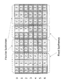
- a fixed subframe is a subframe in which a transmission direction is fixed between different UL / DL configurations.
- the flexible subframe is a subframe whose transmission direction is not fixed between different UL / DL configurations. Therefore, in the flexible subframe, the transmission direction may be different between different UL / DL configurations. Note that the flexible subframes may be called dynamic subframes.
- subframes 0, 1, 2, 5, and 6 are fixed subframes in which the transmission direction is fixed between UL / DL configurations 0 to 6.
- subframes 0, 1, 5, and 6 are all configured as downlink subframes.
- a special subframe is a subframe for switching between a downlink subframe and an uplink subframe, and is mainly used for the downlink. For this reason, the special subframe can be regarded as a downlink subframe.
- subframe 2 is composed of all uplink subframes.
- subframes 3, 4, 7, 8, and 9 are flexible subframes whose transmission directions are not fixed between UL / DL configurations 0 to 6.
- uplink subframes in the case of UL / DL configurations 0, 1, 3, 4, and 6 and downlink subframes in the case of UL / DL configurations 2 and 5 are mixed.
- uplink subframes and downlink subframes are mixed.
- the transmission direction is the same, so the influence of inter-base station interference is small.
- the influence of inter-base station interference is great if the transmission directions are different.
- the fixed subframe and the flexible subframe are not limited to the configuration shown in FIG. 4 and are appropriately changed according to the UL / DL configuration to be used.
- inter-cell uplink / downlink orthogonalization (hereinafter referred to as inter-cell uplink / downlink orthogonalization) dynamic TDD based on frequency domain resource allocation as shown in FIG. 5B is known.
- inter-cell uplink / downlink orthogonalization dynamic TDD orthogonal resources are allocated to UL and DL. Therefore, in the inter-cell uplink / downlink orthogonalization dynamic TDD, UL subframes and DL subframes do not overlap in the same frequency region, so that intercell interference can be reduced.
- the resource utilization efficiency of the inter-cell uplink / downlink orthogonalized dynamic TDD is lower than that of the dynamic TDD with no resource allocation limitation shown in FIG. 5A.
- improved inter-cell uplink / downlink orthogonalization TDD as shown in FIG. 5C has been proposed.
- a dynamic TDD scheme with no restriction on resource allocation is applied in a fixed subframe, and an inter-cell uplink / downlink orthogonalization scheme is applied in a flexible subframe.
- resource utilization efficiency is improved as compared with the inter-cell uplink / downlink orthogonalization dynamic TDD.
- the method as described above is not adapted to the actual interference situation, and may lead to suppression of unnecessary resource use. Therefore, the present inventors use an improved inter-cell uplink / downlink orthogonalization scheme to protect UL transmission when strong interference is detected, and to improve frequency utilization efficiency when the interference level is very limited. Invented an inter-recognition inter-cell uplink / downlink orthogonalization scheme using dynamic TDD with no resource allocation restrictions.
- the interference recognition inter-cell uplink / downlink orthogonalization method can be implemented by a static configuration based on, for example, measurement of interference between base stations.
- the uplink / downlink orthogonalization scheme between interference recognition cells can be implemented by a dynamic configuration based on, for example, immediate interference measurement.
- inter-base station interference may be measured directly, or all interference may be measured, and interference in two interferences, eg, fixed subframe and flexible subframe, respectively. You may measure.
- the interference recognition cell up / down link orthogonalization scheme will be described.
- cell 1 and cell 2 shown in FIG. 6 in order to prevent the uplink signal transmitted from the user terminal from being affected by the interference, cell 1
- the improved inter-cell uplink / downlink orthogonalization TDD is used in the cell 2 radio base station.
- the radio base station of the cell 3 uses dynamic TDD with no resource allocation limitation in order to enhance the scheduling effect.
- Switching of communication (resource allocation) method is performed by selecting a static or quasi-static communication method, or selecting a dynamic or adaptive communication method. Selection of a static or quasi-static communication method will be described in the first mode, and selection of a dynamic or adaptive communication method will be described in a second mode.
- the first mode In the first mode, a case will be described where switching between a method in which resource allocation is not limited statically or semi-statically and an inter-cell uplink / downlink orthogonalization method.
- the RSRP Reference Signal Received Power
- the RSRP Reference Signal Received Power of a radio base station adjacent to the radio base station is measured, and a communication method with no resource allocation limitation or an inter-cell uplink / downlink orthogonalization scheme is selected. Determine whether to use.
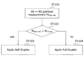
- FIG. 7 is a flowchart showing an interference control method according to the first aspect.
- each radio base station measures a path loss PL BS-NS between the radio base station in its own cell and the radio base station in an adjacent cell (step ST101).
- the path loss is measured based on the RSRP of the neighboring cell regardless of whether or not the radio base station in the neighboring cell is transmitting a data signal.
- the HeNB (Home eNB) method can be reused in the RSRP measurement of the neighboring cell, and the specification beyond that is not affected.
- the measured path loss PL BS-NS is compared with the threshold value PL Thres (step ST102).
- step ST102 the value of the path loss PL BS-NS is smaller than the threshold value PL Thres (step ST102: yes)
- the inter-cell uplink / downlink orthogonalization method is applied (step ST103).
- step ST102 no
- a method with no limitation on resource allocation is applied (step ST104). This is because the smaller the path loss PL BS-NS value is, the stronger interference is received.
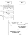
- the radio base station 1 measures the interference received from the radio base station 2 (eNB 2) (step ST111).
- the radio base station 1 requests the radio base station 2 to apply the inter-cell uplink / downlink orthogonalization scheme in, for example, subframes 3 and 8 (step ST113).
- the radio base station 2 applies the inter-cell uplink / downlink orthogonalization scheme in the subframes 3 and 8 (ST114), and signals to that effect to the radio base station 1 (step ST115).
- radio base station 1 applies the inter-cell uplink / downlink orthogonalization scheme in subframes 3 and 8 (step ST116).
- the method without limitation on resource allocation and the inter-cell uplink / downlink orthogonalization method can be used for each subframe in the flexible subframe.
- FIG. 9 is a flowchart showing an interference control method according to the second aspect. As shown in FIG. 9, first, each radio base station measures instantaneous interference or average interference in a fixed subframe (step ST201). Each radio base station measures instantaneous interference or average interference in the flexible subframe (step ST202).
- the radio base station does not need to identify the interference source.
- the interference measurement reflects the scheduling situation of neighboring cells.
- CSMA / CA Carrier Sense Multiple Access with Collision Avoidance
- inter-base station interference is detected (step ST203).
- step ST204 yes
- the inter-cell uplink / downlink orthogonalization scheme is applied (step ST205).
- inter-base station interference is not detected (step ST204: no)
- a method without restriction on resource allocation is applied (step ST206).
- the radio base station measures, for example, a plurality of CSI (Channel State Information) in order to measure interference.
- CSI Channel State Information
- the radio base station transmits the selected communication method to the radio base station in the adjacent cell by backhaul signaling.
- radio base station 1 measures interference in a fixed subframe and interference in a flexible subframe separately (step ST211).
- the radio base station 1 applies the inter-cell uplink / downlink orthogonalization scheme in subframes 3 and 8, for example (step ST213).
- radio base station 1 signals to radio base station 2 (eNB 2) that the inter-cell uplink / downlink orthogonalization scheme has been applied in subframes 3 and 8 (step ST214).
- the radio base station 2 may apply the inter-cell uplink / downlink orthogonalization scheme in the subframes 3 and 8 (step ST215).
- the radio base station 2 signals to the radio base station 1 that the inter-cell uplink / downlink orthogonalization scheme is applied in the subframes 3 and 8 (step ST216).
- the structure which concerns on step ST215,216 in the wireless base station 2 is not forced.
- interference can be measured, for example, by measuring RSRP.
- the HeNB method can be reused.
- the total interference received by the radio base station is estimated by measuring the interference in the fixed subframe and the flexible subframe, respectively.
- CSI may be measured.
- interference may be measured using zero power CSI-RS as CSI-RS (Channel State Information Reference Signal) used for CSI measurement.
- CSI-RS Channel State Information Reference Signal
- transmission power is not distributed to resources to which CSI-RS is allocated, and CSI-RS is muted.
- interference may be measured on the assumption that an inter-cell uplink / downlink orthogonalization scheme is used in a radio base station in an adjacent cell.
- the radio base stations are connected to each other through an inter-base station interface such as an X2 interface.
- Interference control between radio base stations is realized by backhaul signaling via an interface between base stations.
- the radio base station transmits the information according to the following (1) to (4) to the radio base station in the adjacent cell via the inter-base station interface.
- (4) Interference index Based on this index, it is possible to determine whether or not the radio base station selects the inter-cell uplink / downlink orthogonalization scheme.
- the radio base station requests the specific adjacent radio base station to apply the inter-cell uplink / downlink orthogonalization scheme. Which radio base station is required can be identified by a reference signal pattern.
- the radio base station transmits muting resource pattern information such as zero power CSI-RS to the radio base station in the adjacent cell via the inter-base station interface. Based on this information, the radio base station in the adjacent cell can detect or estimate interference more accurately.
- the interference received by the radio base station is measured and detected based on the interference detection result. Since either the frame-free resource allocation scheme or the inter-cell uplink / downlink orthogonalization scheme is applied, interference between base stations can be effectively avoided without suppressing unnecessary resource usage.
- FIG. 11 is a schematic configuration diagram of the radio communication system according to the present embodiment.
- the radio communication system 1 includes a macro base station 11 that forms a macro cell C1 as a first cell, and a small cell C2 that is arranged in the macro cell C1 and is a second cell narrower than the macro cell C1.
- the user terminal 20 is arrange
- the user terminal 20 is arranged in the macro cell C1 and each small cell C2.
- the user terminal 20 is configured to be able to wirelessly communicate with the macro base station 11 and / or the small base station 12.
- the user terminal 20 can communicate with a plurality of small base stations 12 by integrating component carriers used in each small cell C2 (carrier aggregation).
- the user terminal 20 can communicate with the macro base station 11 and the small base station 12 by integrating the component carriers respectively used in the macro cell C1 and the small cell C2.
- Communication between the user terminal 20 and the macro base station 11 is performed using a carrier having a relatively low frequency band (for example, 2 GHz).
- a carrier having a relatively high frequency band for example, 3.5 GHz
- the same frequency band may be used by the macro base station 11 and the small base station 12.
- the macro base station 11 and each small base station 12 may be connected by a relatively low speed (medium delay) line (Non-Ideal backhaul) such as an X2 interface, or may be relatively connected by an optical fiber or the like. It may be connected by a high-speed (low delay) line (Ideal backhaul) or may be connected wirelessly. Also, the small base stations 12 may be connected by a relatively low speed (medium delay) line (Non-Ideal backhaul) such as an X2 interface, or a relatively high speed (low delay) such as an optical fiber. It may be connected by a line (Ideal backhaul) or may be connected wirelessly.
- a relatively low speed (medium delay) line such as an X2 interface
- a relatively high speed (low delay) such as an optical fiber. It may be connected by a line (Ideal backhaul) or may be connected wirelessly.
- the macro base station 11 and each small base station 12 are connected to the higher station apparatus 30 and connected to the core network 40 via the higher station apparatus 30.
- the upper station device 30 includes, for example, an access gateway device, a radio network controller (RNC), a mobility management entity (MME), and the like, but is not limited thereto.
- RNC radio network controller
- MME mobility management entity
- the macro base station 11 is a radio base station having a relatively wide coverage, and may be referred to as an eNodeB (eNB), a radio base station, a transmission point, or the like.
- the small base station 12 is a radio base station having local coverage, and is called RRH (Remote Radio Head), pico base station, femto base station, Home eNodeB (HeNB), transmission point, eNodeB (eNB), or the like. May be.
- the user terminal 20 is a terminal that supports various communication schemes such as LTE and LTE-A, and may include not only a mobile communication terminal but also a fixed communication terminal.
- time division duplex (TDD) that divides the uplink and the downlink by time is applied as a duplex scheme.
- TDD time division duplex
- a UL / DL configuration that indicates a configuration ratio between an uplink subframe and a downlink subframe in a radio frame is used.
- a downlink shared channel (PDSCH: Physical Downlink Shared Channel) shared by each user terminal 20, a downlink control channel (PDCCH: Physical Downlink Control Channel), and EPDCCH: Enhanced Physical. Downlink Control Channel), PCFICH, PHICH, broadcast channel (PBCH), etc.
- PDSCH Physical Downlink Shared Channel
- PDCCH Physical Downlink Control Channel
- EPDCCH Enhanced Physical. Downlink Control Channel
- PCFICH Physical FICH
- PHICH Physical Downlink Control Channel
- PBCH broadcast channel
- an uplink shared channel (PUSCH) shared by each user terminal 20 and an uplink control channel (PUCCH: Physical Uplink Control Channel) are used as uplink communication channels.
- User data and higher layer control information are transmitted by PUSCH.
- downlink radio quality information (CQI: Channel Quality Indicator), delivery confirmation information (ACK / NACK), and the like are transmitted by PUCCH.
- FIG. 12 is an overall configuration diagram of the radio base station 10 (including the radio base stations 11 and 12) according to the present embodiment.
- the radio base station 10 includes a plurality of transmission / reception antennas 101 for MIMO transmission, an amplifier unit 102, a transmission / reception unit 103, a baseband signal processing unit 104, a call processing unit 105, and an interface unit 106. .
- User data transmitted from the radio base station 10 to the user terminal 20 via the downlink is input from the higher station apparatus 30 to the baseband signal processing unit 104 via the interface unit 106.
- the baseband signal processing unit 104 performs PDCP layer processing, user data division / combination, RLC layer transmission processing such as RLC (Radio Link Control) retransmission control transmission processing, MAC (Medium Access Control) retransmission control, for example, HARQ transmission processing, scheduling, transmission format selection, channel coding, Inverse Fast Fourier Transform (IFFT) processing, and precoding processing are performed and transferred to each transceiver 103.
- RLC layer transmission processing such as RLC (Radio Link Control) retransmission control transmission processing, MAC (Medium Access Control) retransmission control, for example, HARQ transmission processing, scheduling, transmission format selection, channel coding, Inverse Fast Fourier Transform (IFFT) processing, and precoding processing are performed and transferred to each transceiver 103.
- HARQ transmission processing scheduling, transmission format selection, channel coding, Inverse Fast Fourier Transform (IFFT) processing, and precoding processing are performed and transferred to each transceiver 103.
- IFFT Inverse Fast Fourier Transform
- Each transmission / reception unit 103 converts the baseband signal output by precoding from the baseband signal processing unit 104 for each antenna to a radio frequency band.
- the amplifier unit 102 amplifies the frequency-converted radio frequency signal and transmits the amplified signal using the transmission / reception antenna 101.
- radio frequency signals received by the respective transmission / reception antennas 101 are amplified by the amplifier units 102 and frequency-converted by the respective transmission / reception units 103. It is converted into a baseband signal and input to the baseband signal processing unit 104.
- the baseband signal processing unit 104 performs FFT processing, IDFT processing, error correction decoding, MAC retransmission control reception processing, RLC layer, and PDCP layer reception processing on user data included in the input baseband signal. And transferred to the upper station apparatus 30 via the interface unit 106.
- the call processing unit 105 performs call processing such as communication channel setting and release, status management of the radio base station 10, and radio resource management.
- the interface unit 106 transmits and receives signals to and from adjacent radio base stations via an interface between radio base stations such as an X2 interface. Alternatively, the interface unit 106 transmits and receives signals to and from the higher station apparatus 30 via a predetermined interface.
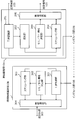
- FIG. 13 is a main functional configuration diagram of the baseband signal processing unit 104 included in the radio base station 10 according to the present embodiment.
- the functional configurations of the radio base station 10a and the adjacent radio base station 10b will be described separately, but one radio base station 10 may have both functional configurations.
- the radio base station 10a and the adjacent radio base station 10b may be two macro base stations 11, two small base stations 12, or both the macro base station 11 and the small base station 12. There may be.
- the radio base station 10a includes an interference recognition unit 201, a selection unit 202, a UL / DL configuration determination unit 203, a scheduling unit 204, and a radio communication unit 205.
- the interference recognition unit 201 measures and detects interference received by the radio base station 10a.
- the interference recognition unit 201 measures interference by measuring the RSRP of the adjacent radio base station 10b, for example. Further, the interference recognition unit 201 estimates the total interference received by the radio base station 10a, for example, by measuring interference in a fixed subframe and a flexible subframe. Alternatively, the interference recognition unit 201 measures interference on the assumption that the inter-cell uplink / downlink orthogonalization scheme is applied in the adjacent radio base station 10b.
- the selection unit 202 selects, based on the interference detection result in the interference recognition unit 201, whether to apply either a method with no resource allocation restriction or an inter-cell uplink / downlink orthogonalization method to each subframe. Specifically, when the interference recognition unit 201 detects strong interference, the selection unit 202 applies the inter-cell uplink / downlink orthogonalization method.
- the selection unit 202 selects the application of a method with no limitation on resource allocation in all fixed subframes in the UL / DL configuration, and a method with no limitation on resource allocation in each flexible subframe in the UL / DL configuration. Alternatively, it is selected whether to apply either the inter-cell uplink / downlink orthogonalization method.
- the communication method selected by the selection unit 202 and applied to each subframe is transmitted from the interface unit 106 to the adjacent radio base station 10b.
- an inter-cell uplink / downlink orthogonalization scheme application request is transmitted from the interface unit 106 to the adjacent radio base station 10b based on the communication scheme applied to each subframe.
- stop resource pattern information such as zero power CSI-RS is transmitted from the interface unit 106 to the adjacent radio base station 10b.
- the UL / DL configuration determination unit 203 determines the UL / DL configuration used for wireless communication with the user terminal 20.
- the UL / DL configuration determining unit 203 may dynamically determine the UL / DL configuration based on traffic information or the like, or may determine it semi-statically.
- the determined UL / DL configuration is notified to the user terminal 20 through, for example, a downlink control channel (PDCCH, EPDCCH), a broadcast channel (PBCH), an SIB (System Information Block), or RRC signaling.
- PDCH downlink control channel
- EPDCCH a downlink control channel
- PBCH broadcast channel
- SIB System Information Block
- the scheduling unit 204 assigns radio resources to the user terminal 20 based on the communication method selected by the selection unit 202, that is, performs scheduling.
- the wireless communication unit 205 performs wireless communication with the user terminal 20 using the communication method selected by the selection unit 202 and the UL / DL configuration determined by the UL / DL configuration determination unit 203. Specifically, the radio communication unit 205 performs downlink signal transmission processing for the user terminal 20, for example, encoding or modulation, according to the scheduling result by the scheduling unit 204. The wireless communication unit 205 performs uplink signal reception processing from the user terminal 20, for example, demodulation and decoding.
- the adjacent radio base station 10b includes an interference control unit 301, a UL / DL configuration determination unit 302, a scheduling unit 303, and a radio communication unit 304.
- the interference control unit 301 performs interference control to apply either a method with no resource allocation limitation or an inter-cell uplink / downlink orthogonalization method to each subframe based on information on the communication method transmitted from the radio base station 10a. Do.
- the UL / DL configuration determination unit 302 determines the UL / DL configuration used for wireless communication with the user terminal 20.
- the UL / DL configuration determination unit 302 may dynamically determine the UL / DL configuration based on instruction information from the interference control unit 301, traffic information, or the like, or may determine it semi-statically. .
- the determined UL / DL configuration is notified to the user terminal 20 through, for example, a downlink control channel (PDCCH, EPDCCH), a broadcast channel (PBCH), an SIB (System Information Block), or RRC signaling.
- PDCH downlink control channel
- EPDCCH a downlink control channel
- PBCH broadcast channel
- SIB System Information Block
- the scheduling unit 303 performs assignment of radio resources to the user terminal 20, that is, scheduling, based on instruction information from the interference control unit 301 and the like.
- the wireless communication unit 304 performs wireless communication with the user terminal 20 using the communication method selected by the interference control unit 301 and the UL / DL configuration determined by the UL / DL configuration determination unit 302. Specifically, the radio communication unit 304 performs downlink signal transmission processing for the user terminal 20, for example, encoding and modulation, according to the scheduling result by the scheduling unit 303. Further, the wireless communication unit 304 performs processing for receiving an uplink signal from the user terminal 20, for example, demodulation and decoding.
- the radio communication system 1 based on the interference detection result in the radio base station 10a, either a method with no resource allocation limitation for each subframe or an inter-cell uplink / downlink orthogonalization method is used. Select whether to apply. Information on this communication method is signaled from the radio base station 10a to the adjacent radio base station 10b via the inter-base station interface. Thereby, the influence of inter-cell interference can be reduced.
Landscapes
- Engineering & Computer Science (AREA)
- Signal Processing (AREA)
- Computer Networks & Wireless Communication (AREA)
- Quality & Reliability (AREA)
- Mobile Radio Communication Systems (AREA)
Abstract
干渉を有効に回避する一方で、干渉を避けるために利用されない無線リソース量を制御すること。無線基地局間インターフェースを介して隣接無線基地局に接続される無線基地局は、無線フレーム内の上りサブフレームと下りサブフレームとの構成を示すUL/DL構成を用いて、ユーザ端末と無線通信を行う無線通信部と、無線基地局が受ける干渉を測定および検出する干渉認識部と、干渉検出結果に基づいて、各サブフレームにリソース割当に制限の無い方式またはセル間上下リンク直交化方式のいずれかを適用するか選択する選択部と、を具備する。
Description
本発明は、時分割複信(TDD:Time Division Duplex)を用いた無線通信システムに適用可能な無線基地局、無線通信システムおよび無線通信方法に関する。
従来、無線通信システムにおける複信方式として、上りリンク(UL:UpLink)と下りリンク(DL:DownLink)とを周波数で分割する周波数分割複信(FDD:Frequency Division Duplex)、および、ULとDLとを時間で分割する時分割複信(TDD:Time Division Duplex)が知られている(たとえば、非特許文献1)。FDDでは、上り信号と下り信号とが、同一時間の異なる周波数で送受信される。一方、TDDでは、上り信号と下り信号とが、同一周波数の異なる時間で送受信される。
また、LTE(Long Term Evolution)システムのTDDにおいては、無線フレーム内における上りサブフレームと下りサブフレームとの構成比率を示すフレーム構成として、UL/DL構成(UL/DL configuration)が規定される(図1参照)。LTEシステムにおいては、図1に示すように、UL/DL構成として7つのフレーム構成が規定されている。
3GPP, TR25.912 (V7.1.0), "Feasibility study for Evolved UTRA and UTRAN", Sept. 2006
一般に、ULのトラヒックとDLのトラヒックは非対称である。また、ULのトラヒックとDLのトラヒックとの比率は一定ではなく、時間的に、あるいは、場所的に変動する。このため、TDDを用いた無線通信システムにおいて、無線リソースの有効利用という観点では、図1に示したUL/DLの構成は、固定されるのではなく、実際のトラヒックの変動に応じて時間的に、あるいは、場所的に変更されることが望ましい。
特に、LTEアドバンスト(LTE-A)システム以降のTDDでは、無線リソースの有効利用を図るために、送受信ポイントごとにULとDLの送信比率を時間領域で動的(Dynamic)に変更すること、すなわちダイナミックTDDが検討されている。一方、ダイナミックTDDでは、隣接セル間において異なる伝送方向が用いられる場合、無線基地局間、すなわちセル間干渉(Inter-cell Interference)やユーザ端末間での干渉が発生するおそれがある。
本発明は、かかる点に鑑みてなされたものであり、干渉を有効に回避する一方で、干渉を避けるために利用されない無線リソース量を制御することができる無線基地局、無線通信システムおよび無線通信方法を提供することを目的とする。
本発明の無線基地局は、無線基地局間インターフェースを介して隣接無線基地局に接続される無線基地局であって、無線フレーム内の上りサブフレームと下りサブフレームとの構成を示すUL/DL構成を用いて、ユーザ端末と無線通信を行う無線通信部と、前記無線基地局が受ける干渉を測定および検出する干渉認識部と、前記干渉検出結果に基づいて、各サブフレームへのセル間直交制限付き周波数領域無線リソース割当方式の適用有無を選択する選択部と、を具備することを特徴とする。
本発明によれば、干渉を有効に回避する一方で、干渉を避けるために利用されない無線リソース量を制御することができる。
図2を参照して、ダイナミックTDDにおけるセル間干渉について説明する。
図2において、セル1における無線基地局とユーザ端末との間、およびセル2における無線基地局とユーザ端末との間では、TDDにより無線通信が行われる。図2におけるセル1では、一例として、ULトラヒックが多いUL/DL構成0を適用している。セル2では、一例として、DLトラヒックが多いUL/DL構成5を適用している。
図2において、セル1における無線基地局とユーザ端末との間、およびセル2における無線基地局とユーザ端末との間では、TDDにより無線通信が行われる。図2におけるセル1では、一例として、ULトラヒックが多いUL/DL構成0を適用している。セル2では、一例として、DLトラヒックが多いUL/DL構成5を適用している。
この場合、サブフレーム4において、セル1における無線基地局ではUL伝送を行い、セル2における無線基地局ではDL伝送を行う。すなわち、同一時間領域/同一周波数領域において、セル1におけるユーザ端末から無線基地局に上り信号が送信され、セル2における無線基地局からユーザ端末に下り信号が送信される。
隣接セルが同一サブフレーム内の異なる送信方向を有することに起因して、干渉が生じる。セル1における無線基地局でのUL受信は、セル2における無線基地局のDL送信によって干渉される(基地局間干渉)。また、セル2におけるユーザ端末のDL受信は、セル1におけるユーザ端末のUL送信によって干渉される(端末間干渉)。
この結果、サブフレーム4において、セル1における無線基地局およびセル2におけるユーザ端末の受信品質が低下するおそれがある。通常、無線基地局から送信される下り信号の送信電力は、ユーザ端末から送信される上り信号の送信電力より大きい。このため、無線基地局から送信される下り信号が、ユーザ端末から送信される上り信号に対して及ぼす基地局間干渉の影響が特に大きい。
一方、図3に示すように、サブフレーム3において、セル1におけるユーザ端末と、セル2におけるユーザ端末とは、共にUL伝送を行う。また、サブフレーム1において、セル1における無線基地局と、セル2における無線基地局とは、共にDL伝送を行う。このような場合には、従来の干渉管理設計として、たとえばeICIC(enhanced Inter-Cell Interference Coordination)やCoMP(Coordinated Multi-Point)などが利用できる。
このように、ダイナミックTDDでは、隣接セルにおける無線基地局間で異なるUL/DL構成を用いる場合、当該無線基地局間で伝送方向が異なるサブフレーム(たとえば、サブフレーム4)では、セル間干渉、特に基地局間干渉の影響を大きく受ける。一方、当該無線基地局間で伝送方向が同じサブフレーム(たとえば、サブフレーム1,3)では、基地局間干渉の影響は少ない。
図4を参照して、基地局間干渉の影響が少ないサブフレームおよび基地局間干渉の影響が大きいサブフレームについて説明する。図4に示すように、無線フレームには、固定サブフレーム(Fixed Subframes)およびフレキシブルサブフレーム(Flexible Subframes)が設けられている。固定サブフレームは、異なるUL/DL構成間で伝送方向が固定されるサブフレームである。フレキシブルサブフレームは、異なるUL/DL構成間で伝送方向が固定されないサブフレームである。したがって、フレキシブルサブフレームにおいては、異なるUL/DL構成間で伝送方向が異なっていてもよい。なお、フレキシブルサブフレームは、ダイナミックサブフレーム(Dynamic Subframes)と呼ばれてもよい。
図4では、サブフレーム0,1,2,5,6は、UL/DL構成0から6間で伝送方向が固定される固定サブフレームである。UL/DL構成0から6において、サブフレーム0,1,5,6は、すべて下りサブフレームで構成される。なお、特殊サブフレーム(Special subframe)は、下りサブフレームと上りサブフレームとの切替用のサブフレームであり、主に、下りリンクに用いられる。このため、特殊サブフレームは、下りサブフレームとみなすことができる。また、UL/DL構成0から6において、サブフレーム2は、すべて上りサブフレームで構成される。
また、図4では、サブフレーム3,4,7,8,9は、UL/DL構成0から6間で伝送方向が固定されないフレキシブルサブフレームである。たとえば、サブフレーム3では、UL/DL構成0,1,3,4,6の場合の上りサブフレームと、UL/DL構成2,5の場合の下りサブフレームと、が混在する。同様に、サブフレーム4,7,8,9でも、上りサブフレームと下りサブフレームとが混在する。
固定サブフレームでは、隣接セルにおける無線基地局間で異なるUL/DL構成が用いられている場合であっても、伝送方向が同一となるため基地局間干渉の影響は少ない。一方、フレキシブルサブフレームでは、隣接セルにおける無線基地局間で異なるUL/DL構成が用いられている場合、伝送方向が異なると基地局間干渉の影響が大きい。
なお、固定サブフレームおよびフレキシブルサブフレームは、図4に示す構成に限られず、用いるUL/DL構成に応じて適宜変更される。
このようなセル間干渉を軽減する方法として、図5Bに示すような周波数領域リソース割当に基づく制限付きセル間上下リンク直交化(以下、セル間上下リンク直交化と呼ぶ)ダイナミックTDDが知られている。セル間上下リンク直交化ダイナミックTDDでは、ULとDLに対して直交リソースが割り当てられる。したがって、セル間上下リンク直交化ダイナミックTDDでは、同一周波数領域においてULサブフレームとDLサブフレームとが重複することがないので、セル間干渉を軽減できる。一方、セル間上下リンク直交化ダイナミックTDDのリソースの利用効率は、図5Aに示すリソース割当に制限の無いダイナミックTDDと比較して低下する。
そこで、図5Cに示すような改良セル間上下リンク直交化TDDが提案されている。改良セル間上下リンク直交化TDDでは、固定サブフレームにおいてリソース割当に制限の無いダイナミックTDD方式を適用し、フレキシブルサブフレームにおいてセル間上下リンク直交化方式を適用する。改良セル間上下リンク直交化TDDでは、セル間上下リンク直交化ダイナミックTDDと比較して、リソースの利用効率が向上する。
しかしながら、以上のような方法は、実際の干渉の状況には非適応であり、不要なリソース利用の抑制につながる可能性がある。そこで、本発明者らは、強い干渉を検出した場合にUL伝送を保護するために改良セル間上下リンク直交化方式を使用し、干渉レベルが非常に限られる場合には周波数利用効率を高めるためにリソース割当に制限の無いダイナミックTDDを使用する、干渉認識セル間上下リンク直交化方式を着想した。
干渉認識セル間上下リンク直交化方式は、たとえば基地局間干渉の測定に基づく静的な構成により実施できる。あるいは、干渉認識セル間上下リンク直交化方式は、たとえば即時の干渉測定に基づく動的な構成により実施できる。動的な構成により実施する場合、基地局間干渉を直接測定してもよいし、すべての干渉を測定してもよいし、2つの干渉、たとえば固定サブフレーム、フレキシブルサブフレームのそれぞれにおける干渉を測定してもよい。
図6を参照して、干渉認識セル間上下リンク直交化方式について説明する。
図6に示すセル1とセル2のような隣接セルにおいて、強い基地局間干渉が検出された場合には、ユーザ端末から送信される上り信号が干渉の影響を受けるのを防ぐために、セル1およびセル2の無線基地局において改良セル間上下リンク直交化TDDを使用する。一方、セル3のように孤立したセルにおいて干渉レベルが非常に限られる場合には、スケジューリング効果を高めるために、セル3の無線基地局においてリソース割当に制限の無いダイナミックTDDを使用する。
図6に示すセル1とセル2のような隣接セルにおいて、強い基地局間干渉が検出された場合には、ユーザ端末から送信される上り信号が干渉の影響を受けるのを防ぐために、セル1およびセル2の無線基地局において改良セル間上下リンク直交化TDDを使用する。一方、セル3のように孤立したセルにおいて干渉レベルが非常に限られる場合には、スケジューリング効果を高めるために、セル3の無線基地局においてリソース割当に制限の無いダイナミックTDDを使用する。
通信(リソース割当)方法の切り替えは、静的あるいは準静的な通信方法の選択、または、動的あるいは適応的な通信方法の選択により行う。静的あるいは準静的な通信方法の選択は第1の態様で説明し、動的あるいは適応的な通信方法の選択は第2の態様で説明する。
(第1の態様)
第1の態様では、静的あるいは準静的にリソース割当に制限の無い方式とセル間上下リンク直交化方式とを切り替える場合について説明する。第1の態様においては、無線基地局が隣接する無線基地局のRSRP(Reference Signal Received Power)を測定して、リソース割当に制限の無い方式とセル間上下リンク直交化方式のどちらの通信方法を用いるか判断する。
第1の態様では、静的あるいは準静的にリソース割当に制限の無い方式とセル間上下リンク直交化方式とを切り替える場合について説明する。第1の態様においては、無線基地局が隣接する無線基地局のRSRP(Reference Signal Received Power)を測定して、リソース割当に制限の無い方式とセル間上下リンク直交化方式のどちらの通信方法を用いるか判断する。
図7は、第1の態様に係る干渉制御方法を示すフローチャートである。図7に示すように、まず、各無線基地局は、自セルにおける無線基地局と隣接セルにおける無線基地局との間のパスロスPLBS-NSを測定する(ステップST101)。パスロスは、隣接セルにおける無線基地局がデータ信号を送信しているか否かに関わらず、隣接セルのRSRPに基づいて測定する。隣接セルがアクティブかどうか調べるためには、準静的に測定と再設定とを行うとよい。
隣接セルのRSRPの測定には、たとえばHeNB(Home eNB)の方法を再利用することができ、それ以上の仕様に影響しない。
続いて、測定したパスロスPLBS-NSの値と、しきい値PLThresとの大小を比較する(ステップST102)。そして、パスロスPLBS-NSの値が、しきい値PLThresよりも小さい場合には(ステップST102:yes)、セル間上下リンク直交化方式を適用する(ステップST103)。パスロスPLBS-NSの値が、しきい値PLThres以上である場合には(ステップST102:no)、リソース割当に制限の無い方式を適用する(ステップST104)。これは、パスロスPLBS-NSの値が小さい方が、強い干渉を受けるためである。
ここで、図8を参照して、第1の態様に係る干渉制御方法の具体例について説明する。まず、無線基地局1(eNB1)は、無線基地局2(eNB2)から受ける干渉を測定する(ステップST111)。強い干渉が検出されると(ステップST112)、無線基地局1は無線基地局2に対して、たとえばサブフレーム3,8においてセル間上下リンク直交化方式を適用するように要求する(ステップST113)。無線基地局2は、要求に応じて、サブフレーム3,8においてセル間上下リンク直交化方式を適用し(ST114)、その旨を無線基地局1にシグナリングする(ステップST115)。その後、無線基地局1は、サブフレーム3,8においてセル間上下リンク直交化方式を適用する(ステップST116)。
このように、リソース割当に制限の無い方式とセル間上下リンク直交化方式とは、フレキシブルサブフレームにおけるサブフレームごとに使い分けることが可能である。
(第2の態様)
第2の態様では、動的あるいは適応的にリソース割当に制限の無い方式とセル間上下リンク直交化方式とを切り替える場合について説明する。固定ULサブフレームとフレキシブルULサブフレームとでは、干渉状態が大きく異なる。そこで、強い基地局間干渉を検出する方法として、これらの違いを活用する。
第2の態様では、動的あるいは適応的にリソース割当に制限の無い方式とセル間上下リンク直交化方式とを切り替える場合について説明する。固定ULサブフレームとフレキシブルULサブフレームとでは、干渉状態が大きく異なる。そこで、強い基地局間干渉を検出する方法として、これらの違いを活用する。
図9は、第2の態様に係る干渉制御方法を示すフローチャート図である。図9に示すように、まず、各無線基地局は、固定サブフレームにおける瞬間の干渉または平均の干渉を測定する(ステップST201)。また、各無線基地局は、フレキシブルサブフレームにおける瞬間の干渉または平均の干渉を測定する(ステップST202)。
このとき、無線基地局は、干渉源を識別する必要はない。また、干渉測定は、隣接セルのスケジューリング状況を反映する。ここでは、CSMA/CA(Carrier Sense Multiple Access with Collision Avoidance)の概念が適用される。
続いて、ステップST201,202での測定結果に基づいて、基地局間干渉を検出する(ステップST203)。基地局間干渉が検出された場合には(ステップST204:yes)、セル間上下リンク直交化方式を適用する(ステップST205)。基地局間干渉が検出されない場合には(ステップST204:no)、リソース割当に制限の無い方式を適用する(ステップST206)。
無線基地局は、干渉を測定するために、たとえば複数のCSI(Channel State Information)を測定する。第2の態様においては、少なくとも固定サブフレームにおけるCSIを1つと、フレキシブルサブフレームにおけるCSIを1つ測定すればよい。また、無線基地局は、選択した通信方法を、バックホールシグナリング(backhaul signaling)によって、隣接セルにおける無線基地局に伝える。
ここで、図10を参照して、第2の態様に係る干渉制御方法の具体例について説明する。まず、無線基地局1(eNB1)は、固定サブフレームにおける干渉とフレキシブルサブフレームにおける干渉とを別々に測定する(ステップST211)。強い干渉が検出されると(ステップST212)、無線基地局1は、たとえばサブフレーム3,8においてセル間上下リンク直交化方式を適用する(ステップST213)。その後、無線基地局1は、サブフレーム3,8においてセル間上下リンク直交化方式を適用したことを無線基地局2(eNB2)にシグナリングする(ステップST214)。
無線基地局2は、この情報に基づいて、サブフレーム3,8においてセル間上下リンク直交化方式を適用してもよい(ステップST215)。この場合には、無線基地局2は、サブフレーム3,8においてセル間上下リンク直交化方式を適用した旨を無線基地局1にシグナリングする(ステップST216)。なお、無線基地局2におけるステップST215,216に係る構成は強制されない。
続いて、上記第1の態様および第2の態様を実現するための、システム要件について説明する。
まず、各無線基地局における干渉測定について説明する。第1の態様においては、たとえばRSRPを測定することにより、干渉を測定できる。RSRPの測定方法としては、HeNBの方法を再利用することができる。
第2の態様においては、固定サブフレームおよびフレキシブルサブフレームにおける干渉をそれぞれ測定することにより、無線基地局が受ける干渉全体を推定する。干渉を測定するためには、たとえばCSIを測定すればよい。このとき、CSIの測定に用いるCSI-RS(Channel State Information Reference Signal)として、ゼロパワーCSI-RSを用いて干渉を測定してもよい。ゼロパワーCSI-RSは、CSI-RSが割り当てられるリソースに送信パワーが分配されず、CSI-RSがミュートされる。
また、各無線基地局において、隣接セルにおける無線基地局におけるセル間上下リンク直交化方式の適用を仮定して干渉を測定してもよい。
続いて、無線基地局間の干渉制御について説明する。無線基地局は、たとえばX2インターフェースなどの基地局間インターフェースで互いに接続される。無線基地局間の干渉制御は、基地局間インターフェースを介したバックホールシグナリングによって実現される。
まず、第1の態様および第2の態様に共通する無線基地局間の干渉制御について説明する。無線基地局は、隣接セルにおける無線基地局に、以下の(1)から(4)に係る情報を、基地局間インターフェースを介して伝送する。
(1)セル間上下リンク直交化方式とリソース割当に制限の無い方式との選択に関する情報。
(2)セル間上下リンク直交化方式を適用するサブフレームに関する情報。
(3)現在のUL/DL構成に関する情報。この情報に基づいて、隣接セルにおける無線基地局がセル間上下リンク直交化方式を適用するサブフレームを導き出すことが可能となる。
(4)干渉指標。この指標に基づいて、無線基地局がセル間上下リンク直交化方式を選択するかどうかを決定することが可能となる。
(1)セル間上下リンク直交化方式とリソース割当に制限の無い方式との選択に関する情報。
(2)セル間上下リンク直交化方式を適用するサブフレームに関する情報。
(3)現在のUL/DL構成に関する情報。この情報に基づいて、隣接セルにおける無線基地局がセル間上下リンク直交化方式を適用するサブフレームを導き出すことが可能となる。
(4)干渉指標。この指標に基づいて、無線基地局がセル間上下リンク直交化方式を選択するかどうかを決定することが可能となる。
第1の態様において、無線基地局は、特定の隣接無線基地局に対して、セル間上下リンク直交化方式の適用を要求する。どの無線基地局に対する要求かは、参照信号のパターンで識別できる。
第2の態様において、無線基地局は、隣接セルにおける無線基地局に、たとえばゼロパワーCSI-RSなどの停止(muting)リソースパターン情報を、基地局間インターフェースを介して伝送する。この情報に基づいて、隣接セルにおける無線基地局は、より正確に干渉の検出または推定することができる。
以上説明したように、本実施の形態に係る干渉認識セル間上下リンク直交化方式を適用することにより、無線基地局が受ける干渉を測定および検出して、この干渉検出結果に基づいて、各サブフレームにリソース割当に制限の無い方式またはセル間上下リンク直交化方式のいずれかを適用するため、不要なリソース利用を抑制することなく、基地局間干渉を有効に回避することができる。
(無線通信システムの構成)
以下、本実施の形態に係る無線通信システムについて、詳細に説明する。この無線通信システムでは、上述の第1の態様または第2の態様に係る干渉制御方法が適用される。
以下、本実施の形態に係る無線通信システムについて、詳細に説明する。この無線通信システムでは、上述の第1の態様または第2の態様に係る干渉制御方法が適用される。
図11は、本実施の形態に係る無線通信システムの概略構成図である。図11に示すように、無線通信システム1は、第1セルとしてのマクロセルC1を形成するマクロ基地局11と、マクロセルC1内に配置され、マクロセルC1よりも狭い第2セルとしてのスモールセルC2を形成するスモール基地局12(12a,12b)とを備えている。また、マクロセルC1および各スモールセルC2には、ユーザ端末20が配置されている。なお、マクロセルC1(マクロ基地局11)、スモールセルC2(スモール基地局12)、ユーザ端末20の数は図11に示すものに限られない。
また、マクロセルC1および各スモールセルC2には、ユーザ端末20が配置されている。ユーザ端末20は、マクロ基地局11および/またはスモール基地局12と無線通信可能に構成されている。また、ユーザ端末20は、各スモールセルC2で用いられるコンポーネントキャリアを統合して(キャリアアグリゲーション)、複数のスモール基地局12と通信できる。あるいは、ユーザ端末20は、マクロセルC1、スモールセルC2でそれぞれ用いられるコンポーネントキャリアを統合して、マクロ基地局11およびスモール基地局12と通信できる。
ユーザ端末20とマクロ基地局11との間は、相対的に低い周波数帯域(たとえば、2GHz)のキャリアを用いて通信が行なわれる。一方、ユーザ端末20とスモール基地局12との間は、相対的に高い周波数帯域(たとえば、3.5GHzなど)のキャリアが用いられるが、これに限られない。マクロ基地局11とスモール基地局12とで同一の周波数帯域が用いられてもよい。
また、マクロ基地局11と各スモール基地局12とは、X2インターフェースなどの相対的に低速(中遅延)の回線(Non-Ideal backhaul)で接続されてもよいし、光ファイバなどの相対的に高速(低遅延)の回線(Ideal backhaul)で接続されてもよいし、無線接続されてもよい。また、スモール基地局12間も、X2インターフェースなどの相対的に低速(中遅延)の回線(Non-Ideal backhaul)で接続されてもよいし、光ファイバなどの相対的に高速(低遅延)の回線(Ideal backhaul)で接続されてもよいし、無線接続されてもよい。
マクロ基地局11および各スモール基地局12は、それぞれ上位局装置30に接続され、上位局装置30を介してコアネットワーク40に接続される。なお、上位局装置30には、たとえば、アクセスゲートウェイ装置、無線ネットワークコントローラ(RNC)、モビリティマネジメントエンティティ(MME)等が含まれるが、これに限定されるものではない。
なお、マクロ基地局11は、相対的に広いカバレッジを有する無線基地局であり、eNodeB(eNB)、無線基地局、送信ポイント(transmission point)などと呼ばれてもよい。スモール基地局12は、局所的なカバレッジを有する無線基地局であり、RRH(Remote Radio Head)、ピコ基地局、フェムト基地局、Home eNodeB(HeNB)、送信ポイント、eNodeB(eNB)などと呼ばれてもよい。ユーザ端末20は、LTE、LTE-Aなどの各種通信方式に対応した端末であり、移動通信端末だけでなく固定通信端末を含んでよい。
無線通信システム1では、複信方式として、上りリンクと下りリンクを時間で分割する時間分割複信(TDD)が適用される。また、無線通信システム1では、無線フレーム内における上りサブフレームと下りサブフレームとの構成比率を示すUL/DL構成が用いられる。
無線通信システム1では、下りリンクの通信チャネルとして、各ユーザ端末20で共有される下り共有チャネル(PDSCH:Physical Downlink Shared Channel)と、下り制御チャネル(PDCCH:Physical Downlink Control Channel)、EPDCCH:Enhanced Physical Downlink Control Channel)、PCFICH、PHICH、報知チャネル(PBCH)などが用いられる。PDSCHにより、ユーザデータや上位レイヤ制御情報が伝送される。PDCCH、EPDCCHにより、下り制御情報(DCI)が伝送される。
無線通信システム1では、上りリンクの通信チャネルとして、各ユーザ端末20で共有される上り共有チャネル(PUSCH:Physical Uplink Shared Channel)と、上り制御チャネル(PUCCH:Physical Uplink Control Channel)などが用いられる。PUSCHにより、ユーザデータや上位レイヤ制御情報が伝送される。また、PUCCHにより、下りリンクの無線品質情報(CQI:Channel Quality Indicator)や、送達確認情報(ACK/NACK)等が伝送される。
図12は、本実施の形態に係る無線基地局10(無線基地局11および12を含む)の全体構成図である。無線基地局10は、MIMO伝送のための複数の送受信アンテナ101と、アンプ部102と、送受信部103と、ベースバンド信号処理部104と、呼処理部105と、インターフェース部106とを備えている。
下りリンクにより無線基地局10からユーザ端末20に送信されるユーザデータは、上位局装置30からインターフェース部106を介してベースバンド信号処理部104に入力される。
ベースバンド信号処理部104では、PDCPレイヤの処理、ユーザデータの分割・結合、RLC(Radio Link Control)再送制御の送信処理などのRLCレイヤの送信処理、MAC(Medium Access Control)再送制御、たとえば、HARQの送信処理、スケジューリング、伝送フォーマット選択、チャネル符号化、逆高速フーリエ変換(IFFT:Inverse Fast Fourier Transform)処理、プリコーディング処理が行われて各送受信部103に転送される。また、下りリンクの制御チャネルの信号に関しても、チャネル符号化や逆高速フーリエ変換等の送信処理が行われて、各送受信部103に転送される。
各送受信部103は、ベースバンド信号処理部104からアンテナごとにプリコーディングして出力されたベースバンド信号を無線周波数帯に変換する。アンプ部102は、周波数変換された無線周波数信号を増幅して送受信アンテナ101により送信する。
一方、上りリンクによりユーザ端末20から無線基地局10に送信されるデータについては、各送受信アンテナ101で受信された無線周波数信号がそれぞれアンプ部102で増幅され、各送受信部103で周波数変換されてベースバンド信号に変換され、ベースバンド信号処理部104に入力される。
ベースバンド信号処理部104では、入力されたベースバンド信号に含まれるユーザデータに対して、FFT処理、IDFT処理、誤り訂正復号、MAC再送制御の受信処理、RLCレイヤ、PDCPレイヤの受信処理がなされ、インターフェース部106を介して上位局装置30に転送される。呼処理部105は、通信チャネルの設定や解放等の呼処理や、無線基地局10の状態管理や、無線リソースの管理を行う。
インターフェース部106は、たとえばX2インターフェースなどの無線基地局間インターフェースを介して、隣接無線基地局と信号を送受信する。あるいは、インターフェース部106は、所定のインターフェースを介して、上位局装置30と信号を送受信する。
図13は、本実施の形態に係る無線基地局10が有するベースバンド信号処理部104の主な機能構成図である。図13では、説明の便宜上、無線基地局10aと隣接無線基地局10bとの機能構成を分けて説明するが、1つの無線基地局10が双方の機能構成を有していてもよい。また、無線基地局10aおよび隣接無線基地局10bは、2つのマクロ基地局11であってもよいし、2つのスモール基地局12であってもよいし、マクロ基地局11およびスモール基地局12であってもよい。
図13に示すように、無線基地局10aは、干渉認識部201と、選択部202と、UL/DL構成決定部203と、スケジューリング部204と、無線通信部205と、を備えている。
干渉認識部201は、無線基地局10aが受ける干渉を測定および検出する。干渉認識部201は、たとえば隣接無線基地局10bのRSRPを測定することにより干渉を測定する。また、干渉認識部201は、たとえば固定サブフレームおよびフレキシブルサブフレームにおける干渉をそれぞれ測定することにより、無線基地局10aが受ける干渉全体を推定する。あるいは、干渉認識部201は、隣接無線基地局10bにおけるセル間上下リンク直交化方式の適用を仮定して干渉を測定する。
選択部202は、干渉認識部201における干渉検出結果に基づいて、各サブフレームにリソース割当に制限の無い方式またはセル間上下リンク直交化方式のいずれかを適用するか選択する。具体的には、選択部202は、干渉認識部201において強い干渉を検出した場合に、セル間上下リンク直交化方式を適用する。
あるいは、選択部202は、UL/DL構成におけるすべての固定サブフレームにおいて、リソース割当に制限の無い方式の適用を選択し、UL/DL構成における各フレキシブルサブフレームにおいて、リソース割当に制限の無い方式またはセル間上下リンク直交化方式のいずれかを適用するか選択する。
選択部202で選択された、各サブフレームに適用する通信方式は、インターフェース部106から隣接無線基地局10bに送信される。または、各サブフレームに適用する通信方式に基づいてセル間上下リンク直交化方式の適用要求が、インターフェース部106から隣接無線基地局10bに送信される。あるいは、ゼロパワーCSI-RSなどの停止リソースパターン情報が、インターフェース部106から隣接無線基地局10bに送信される。
UL/DL構成決定部203は、ユーザ端末20との無線通信に用いられるUL/DL構成を決定する。UL/DL構成決定部203は、トラヒック情報などに基づいて、UL/DL構成を動的に決定してもよいし、準静的に決定してもよい。決定されたUL/DL構成は、たとえば下り制御チャネル(PDCCH,EPDCCH)、報知チャネル(PBCH)、SIB(System Information Block)、またはRRCシグナリングなどによりユーザ端末20に通知される。
スケジューリング部204は、選択部202において選択された通信方式に基づいて、ユーザ端末20に対する無線リソースの割り当て、すなわちスケジューリングを行う。
無線通信部205は、選択部202において選択される通信方式、および、UL/DL構成決定部203で決定されるUL/DL構成を用いて、ユーザ端末20と無線通信を行う。具体的には、無線通信部205は、スケジューリング部204によるスケジューリング結果に従って、ユーザ端末20に対する下り信号の送信処理、たとえば符号化や変調などを行う。また、無線通信部205は、ユーザ端末20からの上り信号の受信処理、たとえば復調や復号などを行う。
一方、隣接無線基地局10bは、干渉制御部301と、UL/DL構成決定部302と、スケジューリング部303と、無線通信部304と、備えている。
干渉制御部301は、無線基地局10aから送信された通信方式に関する情報に基づいて、各サブフレームにリソース割当に制限の無い方式またはセル間上下リンク直交化方式のいずれかを適用する干渉制御を行う。
UL/DL構成決定部302は、ユーザ端末20との無線通信に用いられるUL/DL構成を決定する。UL/DL構成決定部302は、干渉制御部301からの指示情報や、トラヒック情報などに基づいて、UL/DL構成を動的に決定してもよいし、準静的に決定してもよい。決定されたUL/DL構成は、たとえば下り制御チャネル(PDCCH,EPDCCH)、報知チャネル(PBCH)、SIB(System Information Block)、またはRRCシグナリングなどによりユーザ端末20に通知される。
スケジューリング部303は、干渉制御部301からの指示情報などに基づいて、ユーザ端末20に対する無線リソースの割り当て、すなわちスケジューリングを行う。
無線通信部304は、干渉制御部301において選択される通信方式、および、UL/DL構成決定部302で決定されるUL/DL構成を用いて、ユーザ端末20と無線通信を行う。具体的には、無線通信部304は、スケジューリング部303によるスケジューリング結果に従って、ユーザ端末20に対する下り信号の送信処理、たとえば符号化や変調などを行う。また、無線通信部304は、ユーザ端末20からの上り信号の受信処理、たとえば復調や復号などを行う。
以上のように、本実施の形態に係る無線通信システム1では、無線基地局10aにおける干渉検出結果に基づいて、各サブフレームにリソース割当に制限の無い方式またはセル間上下リンク直交化方式のいずれかを適用するか選択する。この通信方式に関する情報は、無線基地局10aから隣接無線基地局10bに、基地局間インターフェースを介してシグナリングされる。これにより、セル間干渉の影響を軽減できる。
以上、上述の実施形態を用いて本発明について詳細に説明したが、当業者にとっては、本発明が本明細書中に説明した実施形態に限定されるものではないということは明らかである。本発明は、特許請求の範囲の記載により定まる本発明の趣旨および範囲を逸脱することなく修正および変更態様として実施することができる。たとえば、上述した複数の態様を適宜組み合わせて適用することができる。したがって、本明細書の記載は、例示説明を目的とするものであり、本発明に対して何ら制限的な意味を有するものではない。
本出願は、2013年6月14日出願の特願2013-125407に基づく。この内容は、すべてここに含めておく。
Claims (10)
- 無線基地局間インターフェースを介して隣接無線基地局に接続される無線基地局であって、
無線フレーム内の上りサブフレームと下りサブフレームとの構成を示すUL/DL構成を用いて、ユーザ端末と無線通信を行う無線通信部と、
前記無線基地局が受ける干渉を測定および検出する干渉認識部と、
前記干渉検出結果に基づいて、各サブフレームへのセル間直交制限付き周波数領域無線リソース割当方式の適用有無を選択する選択部と、を具備することを特徴とする無線基地局。 - 前記選択部は、前記UL/DL構成におけるすべての固定サブフレームにおいて、リソース割当に制限の無い方式の適用を選択し、前記UL/DL構成における各フレキシブルサブフレームにおいて、リソース割当に制限の無い方式またはセル間上下リンク直交化方式のいずれかを適用するか選択することを特徴とする請求項1に記載の無線基地局。
- 前記干渉認識部は、前記隣接無線基地局のRSRPを測定することにより干渉を測定することを特徴とする請求項1に記載の無線基地局。
- 前記干渉認識部は、前記固定サブフレームおよび前記フレキシブルサブフレームにおける干渉をそれぞれ測定することにより、前記無線基地局が受ける干渉全体を推定することを特徴とする請求項1に記載の無線基地局。
- 前記干渉認識部は、前記隣接無線基地局におけるセル間上下リンク直交化方式の適用を仮定して干渉を測定することを特徴とする請求項1に記載の無線基地局。
- 前記各サブフレームに適用する通信方式を、前記無線基地局間インターフェースを介して前記隣接無線基地局に送信するインターフェース部を具備することを特徴とする請求項1に記載の無線基地局。
- 前記各サブフレームに適用する通信方式に基づいてセル間上下リンク直交化方式の適用要求を、前記無線基地局間インターフェースを介して特定の前記隣接無線基地局に送信するインターフェース部を具備することを特徴とする請求項1に記載の無線基地局。
- 停止リソースパターン情報を、前記無線基地局間インターフェースを介して前記隣接無線基地局に送信するインターフェース部を具備することを特徴とする請求項1に記載の無線基地局。
- 無線基地局が無線基地局間インターフェースを介して隣接無線基地局に接続される無線通信システムであって、
前記無線基地局は、
無線フレーム内の上りサブフレームと下りサブフレームとの構成を示すUL/DL構成を用いて、ユーザ端末と無線通信を行う無線通信部と、
前記無線基地局が受ける干渉を測定および検出する干渉認識部と、
前記干渉検出結果に基づいて、各サブフレームにリソース割当に制限の無い方式またはセル間上下リンク直交化方式のいずれかを適用するか選択する選択部と、
前記各サブフレームに適用する通信方式を、前記無線基地局間インターフェースを介して前記隣接無線基地局に送信するインターフェース部と、を具備し、
前記隣接無線基地局は、
前記無線基地局から前記通信方式に関する情報を受信するインターフェース部と、
前記通信方式に関する情報に基づいて、各サブフレームにリソース割当に制限の無い方式またはセル間上下リンク直交化方式のいずれかを適用する干渉制御を行う干渉制御部と、を具備することを特徴とする無線通信システム。 - 無線基地局間インターフェースを介して隣接無線基地局に接続される無線基地局における無線通信方法であって、
無線フレーム内の上りサブフレームと下りサブフレームとの構成を示すUL/DL構成を用いて、ユーザ端末と無線通信を行う工程と、
前記無線基地局が受ける干渉を測定および検出する工程と、
前記干渉検出結果に基づいて、各サブフレームにリソース割当に制限の無い方式またはセル間上下リンク直交化方式のいずれかを適用するか選択する工程と、を有することを特徴とする無線通信方法。
Priority Applications (3)
| Application Number | Priority Date | Filing Date | Title |
|---|---|---|---|
| US14/896,929 US9788332B2 (en) | 2013-06-14 | 2014-05-27 | Radio base station, radio communication system and radio communication method |
| CN201480040156.0A CN105379330A (zh) | 2013-06-14 | 2014-05-27 | 无线基站、无线通信系统以及无线通信方法 |
| EP14810185.0A EP3010268A4 (en) | 2013-06-14 | 2014-05-27 | Wireless base station, wireless communications system, and wireless communications method |
Applications Claiming Priority (2)
| Application Number | Priority Date | Filing Date | Title |
|---|---|---|---|
| JP2013-125407 | 2013-06-14 | ||
| JP2013125407A JP6285647B2 (ja) | 2013-06-14 | 2013-06-14 | 無線基地局、無線通信システムおよび無線通信方法 |
Publications (1)
| Publication Number | Publication Date |
|---|---|
| WO2014199814A1 true WO2014199814A1 (ja) | 2014-12-18 |
Family
ID=52022113
Family Applications (1)
| Application Number | Title | Priority Date | Filing Date |
|---|---|---|---|
| PCT/JP2014/063895 Ceased WO2014199814A1 (ja) | 2013-06-14 | 2014-05-27 | 無線基地局、無線通信システムおよび無線通信方法 |
Country Status (5)
| Country | Link |
|---|---|
| US (1) | US9788332B2 (ja) |
| EP (1) | EP3010268A4 (ja) |
| JP (1) | JP6285647B2 (ja) |
| CN (1) | CN105379330A (ja) |
| WO (1) | WO2014199814A1 (ja) |
Cited By (2)
| Publication number | Priority date | Publication date | Assignee | Title |
|---|---|---|---|---|
| CN112292881A (zh) * | 2018-06-08 | 2021-01-29 | 上海诺基亚贝尔股份有限公司 | 用于动态时分双工的偏差控制 |
| US11044711B2 (en) | 2016-06-16 | 2021-06-22 | Panasonic Intellectual Property Corporation Of America | Base station, terminal, and communication method |
Families Citing this family (14)
| Publication number | Priority date | Publication date | Assignee | Title |
|---|---|---|---|---|
| WO2015111373A1 (ja) | 2014-01-22 | 2015-07-30 | パナソニック インテレクチュアル プロパティ コーポレーション オブ アメリカ | 端末、基地局、送信方法及び受信方法 |
| US10412749B2 (en) | 2015-05-21 | 2019-09-10 | Telefonaktiebolaget Lm Ericsson (Publ) | Scheduling in license assisted access |
| WO2017052332A1 (ko) * | 2015-09-24 | 2017-03-30 | 엘지전자 주식회사 | 무선 통신 시스템에서 단말에 의해 수행되는 로깅 방법 및 상기 방법을 이용하는 단말 |
| US10652902B2 (en) * | 2016-03-31 | 2020-05-12 | Huawei Technologies Co., Ltd. | Method for measuring channel state information, network-side device, and user equipment |
| US11121792B2 (en) * | 2016-08-12 | 2021-09-14 | Lg Electronics Inc. | Resource allocation method for controlling inter-cell interference in wireless communication system operating in flexible duplex mode on a cell-by-cell basis, and apparatus therefor |
| KR102128864B1 (ko) | 2016-09-07 | 2020-07-01 | 후아웨이 테크놀러지 컴퍼니 리미티드 | 통신 방법 및 기지국 |
| US20190280837A1 (en) * | 2016-11-02 | 2019-09-12 | Ntt Docomo, Inc. | User equipment and base station |
| WO2018128428A1 (ko) | 2017-01-08 | 2018-07-12 | 엘지전자 주식회사 | 크로스-링크 간섭을 제어하는 방법 및 이를 위한 장치 |
| CN110622557A (zh) * | 2017-03-17 | 2019-12-27 | 诺基亚技术有限公司 | 用于窄带物联网设备的测量模式确定 |
| WO2018211407A1 (en) * | 2017-05-15 | 2018-11-22 | Telefonaktiebolaget Lm Ericsson (Publ) | Method and node for reducing cross-link interference in a communication network |
| CN109302708A (zh) * | 2017-07-24 | 2019-02-01 | 中国移动通信有限公司研究院 | 一种基于交叉链路干扰测量的帧结构配置方法和基站 |
| CN117715225A (zh) * | 2017-11-27 | 2024-03-15 | 交互数字专利控股公司 | Nr/nr-u中的初始接入和信道接入 |
| KR102566509B1 (ko) * | 2018-10-08 | 2023-08-16 | 삼성전자주식회사 | 동적 시분할 듀플렉스 환경에서 셀 간 간섭 완화 방법 및 그 전자 장치 |
| JP7809456B2 (ja) | 2021-06-22 | 2026-02-02 | キヤノン株式会社 | 基地局装置、中継装置、制御方法、およびプログラム |
Citations (2)
| Publication number | Priority date | Publication date | Assignee | Title |
|---|---|---|---|---|
| WO2011126024A1 (ja) * | 2010-04-06 | 2011-10-13 | 京セラ株式会社 | 無線通信システム、無線基地局、及び通信制御方法 |
| JP2012129793A (ja) * | 2010-12-15 | 2012-07-05 | Ntt Docomo Inc | 基地局、及び保護サブフレーム使用状況通知方法 |
Family Cites Families (9)
| Publication number | Priority date | Publication date | Assignee | Title |
|---|---|---|---|---|
| JP5157510B2 (ja) * | 2008-02-19 | 2013-03-06 | 富士通株式会社 | 無線通信制御方法および無線端末 |
| US20120113875A1 (en) * | 2009-01-27 | 2012-05-10 | Nokia Corporation | Method and apparatus for dynamically modifying a transmission frame |
| TWI497958B (zh) * | 2010-06-18 | 2015-08-21 | Mediatek Inc | 通訊裝置、通訊裝置間協調傳輸以及指定近乎空白子訊框圖樣的方法 |
| US8724492B2 (en) * | 2011-04-08 | 2014-05-13 | Motorola Mobility Llc | Method and apparatus for multi-radio coexistence on adjacent frequency bands |
| US20130003578A1 (en) * | 2011-07-01 | 2013-01-03 | Teck Hu | User Equipment Restricted Measurements For Multimedia Broadcast Single Frequency Network Networks |
| US20140146719A1 (en) * | 2011-07-08 | 2014-05-29 | Broadcom Corporation | Methods, apparatuses and computer program products for interference mitigation via channel reservation in la tdd network |
| EP2907338B1 (en) * | 2012-10-12 | 2018-05-23 | NEC Corporation | Communications node |
| WO2014182041A1 (ko) * | 2013-05-07 | 2014-11-13 | 엘지전자 주식회사 | 무선 통신 시스템에서 측정 수행 방법 및 장치 |
| JP6111144B2 (ja) * | 2013-06-03 | 2017-04-05 | 株式会社Nttドコモ | 無線基地局、無線通信システム及び無線通信方法 |
-
2013
- 2013-06-14 JP JP2013125407A patent/JP6285647B2/ja not_active Expired - Fee Related
-
2014
- 2014-05-27 WO PCT/JP2014/063895 patent/WO2014199814A1/ja not_active Ceased
- 2014-05-27 CN CN201480040156.0A patent/CN105379330A/zh active Pending
- 2014-05-27 US US14/896,929 patent/US9788332B2/en not_active Expired - Fee Related
- 2014-05-27 EP EP14810185.0A patent/EP3010268A4/en not_active Withdrawn
Patent Citations (2)
| Publication number | Priority date | Publication date | Assignee | Title |
|---|---|---|---|---|
| WO2011126024A1 (ja) * | 2010-04-06 | 2011-10-13 | 京セラ株式会社 | 無線通信システム、無線基地局、及び通信制御方法 |
| JP2012129793A (ja) * | 2010-12-15 | 2012-07-05 | Ntt Docomo Inc | 基地局、及び保護サブフレーム使用状況通知方法 |
Non-Patent Citations (7)
| Title |
|---|
| "Feasibility study for Evolved UTRA and UTRAN", 3GPP, TR25.912 (V7.1.0), September 2006 (2006-09-01) |
| CATT: "Discussion on other interference mitigation schemes", 3GPP TSG RAN WG1 MEETING #73, R1-131881, 11 May 2013 (2013-05-11), pages 1 - 4, XP050697667 * |
| FUJITSU: "CSI-RS Patterns for Interference Measurements for CoMP", 3GPP TSG-RAN WG1 #68BIS, R1-121188, 20 March 2012 (2012-03-20), pages 1 - 9, XP050599486 * |
| INTEL CORPORATION: "Discussion on backhaul signaling and inter-eNB measurements to support DL-UL interference mitigation schemes", 3GPP TSG RAN WG1 MEETING #73, R1-132392, 11 May 2013 (2013-05-11), pages 1 - 5, XP050698156 * |
| NEW POSTCOM: "Considerations on issues of interference mitigation schemes", 3GPP TSG RAN WG1 MEETING #73, R1-132199, 11 May 2013 (2013-05-11), pages 1 - 4, XP050697971 * |
| NTT DOCOMO: "Interference Mitigation Schemes for eIMTA", 3GPP TSG RAN WG1 MEETING #72BIS, R1-131669, 16 April 2013 (2013-04-16), pages 1 - 6, XP050697451 * |
| See also references of EP3010268A4 |
Cited By (2)
| Publication number | Priority date | Publication date | Assignee | Title |
|---|---|---|---|---|
| US11044711B2 (en) | 2016-06-16 | 2021-06-22 | Panasonic Intellectual Property Corporation Of America | Base station, terminal, and communication method |
| CN112292881A (zh) * | 2018-06-08 | 2021-01-29 | 上海诺基亚贝尔股份有限公司 | 用于动态时分双工的偏差控制 |
Also Published As
| Publication number | Publication date |
|---|---|
| JP2015002403A (ja) | 2015-01-05 |
| US20160143042A1 (en) | 2016-05-19 |
| JP6285647B2 (ja) | 2018-02-28 |
| US9788332B2 (en) | 2017-10-10 |
| CN105379330A (zh) | 2016-03-02 |
| EP3010268A1 (en) | 2016-04-20 |
| EP3010268A4 (en) | 2017-03-01 |
Similar Documents
| Publication | Publication Date | Title |
|---|---|---|
| JP6285647B2 (ja) | 無線基地局、無線通信システムおよび無線通信方法 | |
| JP6100829B2 (ja) | ユーザ端末、無線基地局及び無線通信方法 | |
| JP6204693B2 (ja) | 無線基地局及び無線通信方法 | |
| JP6111144B2 (ja) | 無線基地局、無線通信システム及び無線通信方法 | |
| CA3012033C (en) | User terminal, radio base station, and radio communication method | |
| JP6472463B2 (ja) | 無線基地局、ユーザ端末及び無線通信方法 | |
| CN105934992B (zh) | 用户终端、无线基站以及无线通信方法 | |
| JP5781016B2 (ja) | 無線基地局、無線通信システム及び無線通信方法 | |
| CN110603834A (zh) | 用户终端以及无线通信方法 | |
| WO2014136511A1 (ja) | 無線基地局、ユーザ端末、無線通信システム及び無線通信方法 | |
| TW201540011A (zh) | 用於協調小區間干擾之方法與裝置 | |
| JPWO2017135344A1 (ja) | ユーザ端末、無線基地局及び無線通信方法 | |
| WO2013183541A1 (ja) | 無線通信方法、無線通信システム、無線基地局及びユーザ端末 | |
| US9712271B2 (en) | Radio base station, user terminal and radio communication method | |
| CN103875300B (zh) | 无线通信系统、无线基站装置、用户终端以及无线通信方法 | |
| JP7074682B2 (ja) | 端末、無線通信方法及びシステム | |
| JP2018033169A (ja) | 無線基地局、ユーザ端末及び無線通信方法 | |
| JPWO2016017357A1 (ja) | 無線基地局、ユーザ端末及び無線通信方法 | |
| JP2016015765A (ja) | 無線基地局、無線通信システム及び無線通信方法 |
Legal Events
| Date | Code | Title | Description |
|---|---|---|---|
| 121 | Ep: the epo has been informed by wipo that ep was designated in this application |
Ref document number: 14810185 Country of ref document: EP Kind code of ref document: A1 |
|
| WWE | Wipo information: entry into national phase |
Ref document number: 14896929 Country of ref document: US |
|
| NENP | Non-entry into the national phase |
Ref country code: DE |
|
| WWE | Wipo information: entry into national phase |
Ref document number: 2014810185 Country of ref document: EP |