WO2014199828A1 - ガスエンジン - Google Patents
ガスエンジン Download PDFInfo
- Publication number
- WO2014199828A1 WO2014199828A1 PCT/JP2014/064114 JP2014064114W WO2014199828A1 WO 2014199828 A1 WO2014199828 A1 WO 2014199828A1 JP 2014064114 W JP2014064114 W JP 2014064114W WO 2014199828 A1 WO2014199828 A1 WO 2014199828A1
- Authority
- WO
- WIPO (PCT)
- Prior art keywords
- valve
- output
- oxygen sensor
- gas engine
- average value
- Prior art date
- Legal status (The legal status is an assumption and is not a legal conclusion. Google has not performed a legal analysis and makes no representation as to the accuracy of the status listed.)
- Ceased
Links
Images


Classifications
-
- F—MECHANICAL ENGINEERING; LIGHTING; HEATING; WEAPONS; BLASTING
- F02—COMBUSTION ENGINES; HOT-GAS OR COMBUSTION-PRODUCT ENGINE PLANTS
- F02D—CONTROLLING COMBUSTION ENGINES
- F02D41/00—Electrical control of supply of combustible mixture or its constituents
- F02D41/02—Circuit arrangements for generating control signals
- F02D41/14—Introducing closed-loop corrections
- F02D41/1438—Introducing closed-loop corrections using means for determining characteristics of the combustion gases; Sensors therefor
- F02D41/1439—Introducing closed-loop corrections using means for determining characteristics of the combustion gases; Sensors therefor characterised by the position of the sensor
- F02D41/1441—Plural sensors
-
- F—MECHANICAL ENGINEERING; LIGHTING; HEATING; WEAPONS; BLASTING
- F02—COMBUSTION ENGINES; HOT-GAS OR COMBUSTION-PRODUCT ENGINE PLANTS
- F02D—CONTROLLING COMBUSTION ENGINES
- F02D41/00—Electrical control of supply of combustible mixture or its constituents
- F02D41/30—Controlling fuel injection
-
- F—MECHANICAL ENGINEERING; LIGHTING; HEATING; WEAPONS; BLASTING
- F02—COMBUSTION ENGINES; HOT-GAS OR COMBUSTION-PRODUCT ENGINE PLANTS
- F02D—CONTROLLING COMBUSTION ENGINES
- F02D41/00—Electrical control of supply of combustible mixture or its constituents
- F02D41/0025—Controlling engines characterised by use of non-liquid fuels, pluralities of fuels, or non-fuel substances added to the combustible mixtures
- F02D41/0027—Controlling engines characterised by use of non-liquid fuels, pluralities of fuels, or non-fuel substances added to the combustible mixtures the fuel being gaseous
-
- F—MECHANICAL ENGINEERING; LIGHTING; HEATING; WEAPONS; BLASTING
- F02—COMBUSTION ENGINES; HOT-GAS OR COMBUSTION-PRODUCT ENGINE PLANTS
- F02D—CONTROLLING COMBUSTION ENGINES
- F02D41/00—Electrical control of supply of combustible mixture or its constituents
- F02D41/02—Circuit arrangements for generating control signals
- F02D41/14—Introducing closed-loop corrections
- F02D41/1438—Introducing closed-loop corrections using means for determining characteristics of the combustion gases; Sensors therefor
- F02D41/1444—Introducing closed-loop corrections using means for determining characteristics of the combustion gases; Sensors therefor characterised by the characteristics of the combustion gases
- F02D41/1454—Introducing closed-loop corrections using means for determining characteristics of the combustion gases; Sensors therefor characterised by the characteristics of the combustion gases the characteristics being an oxygen content or concentration or the air-fuel ratio
- F02D41/1456—Introducing closed-loop corrections using means for determining characteristics of the combustion gases; Sensors therefor characterised by the characteristics of the combustion gases the characteristics being an oxygen content or concentration or the air-fuel ratio with sensor output signal being linear or quasi-linear with the concentration of oxygen
-
- F—MECHANICAL ENGINEERING; LIGHTING; HEATING; WEAPONS; BLASTING
- F02—COMBUSTION ENGINES; HOT-GAS OR COMBUSTION-PRODUCT ENGINE PLANTS
- F02M—SUPPLYING COMBUSTION ENGINES IN GENERAL WITH COMBUSTIBLE MIXTURES OR CONSTITUENTS THEREOF
- F02M21/00—Apparatus for supplying engines with non-liquid fuels, e.g. gaseous fuels stored in liquid form
- F02M21/02—Apparatus for supplying engines with non-liquid fuels, e.g. gaseous fuels stored in liquid form for gaseous fuels
-
- F—MECHANICAL ENGINEERING; LIGHTING; HEATING; WEAPONS; BLASTING
- F02—COMBUSTION ENGINES; HOT-GAS OR COMBUSTION-PRODUCT ENGINE PLANTS
- F02D—CONTROLLING COMBUSTION ENGINES
- F02D2200/00—Input parameters for engine control
- F02D2200/02—Input parameters for engine control the parameters being related to the engine
- F02D2200/06—Fuel or fuel supply system parameters
- F02D2200/0611—Fuel type, fuel composition or fuel quality
-
- Y—GENERAL TAGGING OF NEW TECHNOLOGICAL DEVELOPMENTS; GENERAL TAGGING OF CROSS-SECTIONAL TECHNOLOGIES SPANNING OVER SEVERAL SECTIONS OF THE IPC; TECHNICAL SUBJECTS COVERED BY FORMER USPC CROSS-REFERENCE ART COLLECTIONS [XRACs] AND DIGESTS
- Y02—TECHNOLOGIES OR APPLICATIONS FOR MITIGATION OR ADAPTATION AGAINST CLIMATE CHANGE
- Y02T—CLIMATE CHANGE MITIGATION TECHNOLOGIES RELATED TO TRANSPORTATION
- Y02T10/00—Road transport of goods or passengers
- Y02T10/10—Internal combustion engine [ICE] based vehicles
- Y02T10/30—Use of alternative fuels, e.g. biofuels
Definitions
- the present invention relates to a gas engine that can cope with a change in combustion calories of fuel gas (hereinafter simply referred to as “calories”).
- control of the air-fuel ratio in a gas engine is set so as to correspond to a fuel gas having a constant composition.
- the composition of the actually supplied fuel gas is not constant, the calorie of the fuel gas is also reduced. It is not constant but changes.
- the gas composition measuring device such as gas chromatography has to be periodically replaced because the column deteriorates due to use over time, which increases costs and labor costs.
- gas composition measuring devices such as gas chromatography change the calibration curve due to climate change or column deterioration, etc., so it is necessary to recreate the calibration curve periodically using standard gas, which is cumbersome to handle. Cannot be used in places where there is a great difference in temperature.
- the fuel gas supplied to the cylinder head does not become the fuel gas whose composition has been measured but causes a deviation. For this reason, it is conceivable to devise the fuel gas supply path and send the fuel gas whose measurement result is output to the cylinder head, but in this case, the apparatus becomes complicated.
- the present invention has been made in view of such circumstances, and an object thereof is to provide a gas engine capable of performing air-fuel ratio control in response to a change in calorie of fuel gas.
- a gas engine includes a first valve having a lower responsiveness and a larger fuel flow rate adjustment width than the second valve, and a higher responsiveness and a smaller fuel flow rate adjustment width than the first valve.
- the second valve is perturbed by changing the second valve from the predetermined opening to the lean side and the rich side with the first valve opened to a predetermined opening.
- the control unit is configured so that the average value of the output of the oxygen sensor provided in the exhaust path of the gas engine is the output target of the oxygen lancet set in the control unit under the condition When the output value deviates from the value, the opening degree of the first valve is adjusted so that the output average value becomes the output target value.
- control unit extracts the maximum output and the minimum output of the oxygen sensor corresponding to the maximum opening and the minimum opening in the perturbation control by the second valve during actual operation, and outputs an average value. May be calculated.
- control unit may adjust the opening of the first valve so as to converge to a wide output target value.
- the first valve and the second valve may be provided for each cylinder head or for each of a plurality of cylinder heads.
- first valves and / or second valves may be provided.
- the oxygen sensor may be a pre-oxygen sensor provided upstream of the catalyst in the exhaust path.
- the oxygen sensor may be an oxygen sensor that is provided downstream of the catalyst in the exhaust path.
- air-fuel ratio control can be performed in response to a change in the composition of the fuel gas.
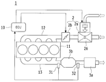
- FIG. 1 shows an outline of the overall configuration of a gas engine 1 according to the present invention
- FIG. 2 shows a mixing section 2a of fuel gas and intake air in the gas engine 1
- FIG. 3 shows a control section 10 of the gas engine 1.
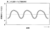
- FIG. 4 shows a graph for explaining the calculation method of the output average value b
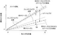
- FIG. 5 shows a graph for explaining the valve characteristics of the solenoid valve 21 and the A / F valve 22, and
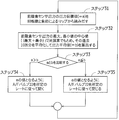
- FIG. 6 shows a control flow by the control unit 10 considering the calorie change of the fuel gas.
- the gas engine 1 includes a solenoid valve 21 and an A / F valve 22 and is configured to perform perturbation by the solenoid valve 21.
- the output average value b obtained from the pre-oxygen sensor 31 provided in the exhaust path 13 of the gas engine 1 is set so that the output target value a of the pre-oxygen sensor 31 set in the control unit 10 under the condition is A.
- the opening degree of the / F valve 22 is adjusted.
- a mixing unit 2 a that mixes air and fuel gas is provided in an intake passage 12 connected to the cylinder head 11.
- a throttle valve 2 b is provided between the mixing unit 2 a and the cylinder head 11. Is provided.
- the mixing unit 2a and the throttle valve 2b constitute an intake unit 2, and the intake unit 2 is controlled by a signal from the control unit 10.
- a solenoid valve 21, an A / F valve 22, a main jet 23, and an adjusting screw 24 are connected in parallel between a regulator 25 and a mixer 26.
- the solenoid valve 21 is configured such that a movable valve biased to close the flow path by a biasing force such as a leaf spring or a spring is moved by an electromagnetic coil and opened to a predetermined opening degree.
- the solenoid valve 21 is opened and closed at a speed of 25 Hz, for example, and the opening degree can be adjusted by changing the duty ratio at the time of opening and closing.
- the solenoid valve 21 is not limited to the one having a frequency of 25 Hz, and may be a solenoid valve 21 having various frequencies used in this kind of perturbation control. With this configuration, the solenoid valve 21 has a small flow rate adjustment range, but allows quick flow rate adjustment. Further, the flow characteristic valve constituting the solenoid valve 21 may be constituted by a proportional control valve.
- the A / F valve 22 is configured so that the opening degree of the movable valve can be adjusted for each step by the rotation of the stepping motor. With this configuration, the A / F valve 22 cannot perform quick flow rate adjustment, but has a large flow rate adjustment range so that it can accommodate a wide range of excess air ratio.
- the main jet 23 is a valve configured to adjust the amount of fuel flowing from the regulator 25 to the mixer 26 together with the solenoid valve 21 and the A / F valve 22, and is different from the solenoid valve 21 and the A / F valve 22 described above.
- the opening is fixed by the number of the main jet 23 to be used.
- the adjustment screw 24 is a valve configured to manually adjust the amount of fuel gas, and is usually fixed together with the main jet 23.
- the regulator 25 controls the pressure of the fuel gas so that the fuel gas can be always supplied at a constant pressure.
- the mixer 26 is composed of a venturi tube that mixes air and fuel gas.
- the mixer 26 is configured to mix fuel gas and air by the venturi effect of the air sucked according to the opening degree of the throttle valve 2b provided on the downstream side.
- a silencer 3 a is provided in the exhaust path 13 connected to the cylinder head 11, and a three-way catalyst 3 b is provided between the silencer 3 a and the cylinder head 11.
- a pre-oxygen sensor 31 is provided on the exhaust gas inlet side of the three-way catalyst 3b, and another post-oxygen sensor 32 is provided on the outlet side.
- the A / F valve 22 is controlled by the control unit 10 with the solenoid valve 21 closed.
- the solenoid valve 21 is opened at an intermediate opening in the open / close region, for example, an opening of 50%, and the solenoid valve 21 is repeatedly opened and closed at a predetermined pitch from the opening of 50% to change the opening. This is performed under the control of the control unit 10.
- the solenoid valve 21 and the A / F valve 22 are set to an intermediate opening degree in the open / close region because the intermediate opening amount is smaller than a small opening or a large opening region. This is because the accuracy of proportional control is high. Therefore, it is not necessary to stick to such an intermediate opening when the accuracy of proportional control is the same over the entire opening / closing area by performing correction control in a small opening area or a large opening area.
- the A / F valve 22 may be set to an opening larger than the intermediate opening during the stoichiometric operation in consideration of closing during the lean operation. preferable.
- the controller 10 opens the solenoid valve 21 and the A / F valve 22, the front oxygen sensor 31, the rear oxygen sensor 32, A relationship with a detection result from an area sensor (not shown) is input, and the stoichiometric operation and lean operation are controlled according to this input information.
- This perturbation control is performed by the control unit 10 as follows.
- the oxygen concentration of the exhaust gas immediately before flowing into the three-way catalyst 3 b is measured by the pre-oxygen sensor 31.
- the pre-oxygen sensor 31 closes the solenoid valve 21 to the lean side more excessively than the stoichiometric operation is set.
- a post-oxygen sensor 32 provided on the rear stage side of the three-way catalyst 3b. Shifts to the lean side after a predetermined response time from switching of the solenoid valve 21.
- the pre-oxygen sensor 31 on the upstream side of the three-way catalyst 3b is determined to be lean when the solenoid valve 21 is closed to the lean side with respect to the stoichiometric condition. Open to the rich side excessively than the stoichiometric setting.
- the oxygen stored in the three-way catalyst 3b is released into the exhaust gas to purify the exhaust gas, but the oxygen stored in the three-way catalyst 3b is depleted, so that the rear side of the three-way catalyst 3b
- the post-oxygen sensor 32 provided at the position shifts to the rich side after a predetermined response time from the switching of the solenoid valve 21.
- the air-fuel ratio changes gently between the lean side and the rich side.
- the three-way catalyst 3b repeats the occlusion and release of oxygen, so that the activated state of the catalyst is maintained.
- the control map as shown in FIG. 3 is input to the control unit 10, and when the stoichiometric operation is performed using the fuel gas of a predetermined calorie, the control according to the control map is performed.
- the control unit 10 performs the pre-oxygenation within a certain period of time when the driving situation is considered stable.
- the output average value b in the actual driving situation is calculated from the history of the output value of the oxygen concentration of the sensor 31.
- the average output value b is calculated by measuring the output value of the oxygen concentration that changes by perturbation control at each stage, as shown in FIG. In FIG. 4, the output values for three cycles are averaged, but the output values are not particularly limited to three cycles, and even if the output values for one cycle or two cycles are averaged.
- the output average value b may be calculated by averaging output values of three cycles or more.
- the control unit 10 compares the output average value b in the actual driving situation calculated in this way with the original output target value a in the same condition input to the control unit 10.
- the degree of opening of the A / F valve 22 is opened.
- the output average value b is equal to or larger than the output target value a, the output is large.
- the opening degree of the A / F valve 22 is maintained or further closed, and the output average value b and the output target value a are controlled to coincide with each other.
- the control by the control unit 10 is performed as described above. However, when the calorie of the actually supplied fuel gas is lower than the reference, or actually supplied When the calorie of the fuel gas is higher than the reference, as shown in FIG. 5, the A / F valve 22 having a large flow rate adjustment width is opened and closed so that the A / F valve 22 matches the fuel gas calorie. It is necessary to reset the opening.
- the solenoid valve 21 is fully opened or fully closed in a state where the A / F valve 22 is opened to match the low calorie gas or opened to match the high calorie gas, the flow rate adjustment range by the solenoid valve 21 Vl and Vh are limited, and the range from the low calorie fuel gas to the high calorie fuel gas cannot be controlled by the solenoid valve 21 alone.
- the control unit 10 controls the solenoid valve 21 to open and close while maintaining the opening of the A / F valve 22 as in the above-described perturbation control
- the calorie of the fuel gas changes.
- the change is mixed with the perturbation control by the solenoid valve 21, and it cannot be determined whether the change is caused by the perturbation control or the calorie change of the fuel gas. Therefore, in an actual driving situation, even when the calorie of the fuel gas changes, the solenoid valve 21 capable of quick flow rate adjustment follows the change and is controlled by the solenoid valve 21.
- the solenoid valve 21 perturbs in a direction that opens more or closes, but the control range of the solenoid valve 21 is narrow. As a result, it is immediately outside the controllable range and becomes uncontrollable.
- the opening degree is adjusted not by the solenoid valve 21 but by the A / F valve 22.
- the control unit 10 is controlled as follows.
- This stoichiometric operation is executed by adjusting the opening degree of the A / F valve 22 while keeping the time average value of the opening degree of the solenoid valve 21 at 50%.
- the opening of the A / F valve 22 is also the opening previously set in the control unit 10 if the stoichiometric operation is performed at a predetermined engine speed or load. That is, the opening should be 50%.
- the fuel gas supplied to the gas engine 1 during actual operation is not guaranteed to be the same, and the calorie of the fuel gas increases or decreases during the day depending on the region.
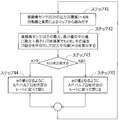
- a predetermined engine speed and load are detected during the stoichiometric operation, and the pre-oxygen set in the control unit 10 under these conditions is detected.
- the output target value a of the sensor 31 is read (step 1).
- the output history of the pre-oxygen sensor 31 in the actual driving situation is traced back from the time when the output target value a is read, and the average value of the output history of the pre-oxygen sensor 31 over a certain time is calculated as the output average value b (step 2). ).
- Step 3 If the calorie of the fuel gas has not changed, the output target value a read in step 1 and the output average value b calculated in step 2 match, so the output target value a and the output average value b are compared. (Step 3).
- the calorie of the fuel gas is small by the difference, and the excess air ratio detected by the pre-oxygen sensor 31 starts to shift to the lean side.
- the A / F valve 22 is opened according to the rate (step 4).
- the calorie of the fuel gas is larger by the difference, and the excess air ratio measured by the pre-oxygen sensor 31 starts to shift to the rich side.
- the A / F valve 22 is closed according to the rate. Further, when the output average value b is the same as the output target value a, the calorie of the fuel gas has not changed and the excess air ratio measured by the pre-oxygen sensor 31 has not deviated.
- the / F valve 22 maintains the opening degree (step 5).
- step 1 Thereafter, the control from step 1 is repeated.
- control unit 10 compares the output target value a obtained from the pre-oxygen sensor 31 and the output average value b to adjust the opening degree of the A / F valve 22.
- the output target value a obtained from the oxygen sensor 32 provided on the exhaust gas outlet side of the three-way catalyst 3b is compared with the output average value b to adjust the opening degree of the A / F valve 22. Also good.
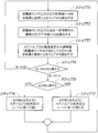
- FIG. 7 shows a control flow of the control unit 10 when the output target value a obtained from the post oxygen sensor 32 and the output average value b are compared to adjust the opening degree of the A / F valve 22.
- the output history of the rear oxygen sensor 32 in the actual driving situation is traced back from the time when the output target value a is read, and the average value of the output history of the rear oxygen sensor 32 over a certain time is calculated as the output average value b (step 22). ).
- Step 23 If the calorie of the fuel gas has not changed, the output target value a read in step 21 and the output average value b calculated in step 22 match, so the output target value a and the output average value b are compared. (Step 23).
- the calorie of the fuel gas is small by the difference, and the excess air ratio detected by the post oxygen sensor 32 starts to shift to the lean side.
- the A / F valve 22 is opened according to the rate (step 24).
- the calorie of the fuel gas is larger by the difference, and the excess air ratio measured by the rear oxygen sensor 32 starts to shift to the rich side.
- the A / F valve 22 is closed according to the rate. Further, when the output average value b is the same as the output target value a, the calorie of the fuel gas has not changed and the excess air ratio measured by the post oxygen sensor 32 has not deviated.
- the / F valve 22 maintains the opening (step 25).
- step 21 Thereafter, the control from step 21 is repeated.
- the gas engine 1 outputs the output of the pre-oxygen sensor 31 or the post-oxygen sensor 32 in the perturbation control when the fuel gas whose calorie is lower or higher than the reference fuel gas is supplied.
- This can be dealt with by adjusting the opening of the A / F valve 22 instead of the solenoid valve 21 that is linked to the value, so even if the calorie of the fuel gas changes greatly, it can cope with the change.
- the perturbation control of the stoichiometric operation by the solenoid valve 21 can be continuously performed. Therefore, the period during which the exhaust gas purification performance can be maintained becomes longer, and the maintenance interval can be extended.
- the gas engine 1 can be operated even when fuel gas having a large calorie change is used. Further, the fuel gas can be used in a plurality of countries and regions having different calories.
- the gas flow rate adjustment width Vl when the solenoid valve 21 is fully closed to fully open and when the high-calorie gas is supplied, the solenoid valve Since the gas flow rate adjustment width Vh when the valve 21 is changed from fully closed to fully opened is different from the gas flow rate adjustment width Vh, if the perturbation control is performed with the same amount of opening change, the fluctuation of the air-fuel ratio is caused when high calorie gas is supplied When the width becomes large and low calorie gas is supplied, the fluctuation range of the air-fuel ratio becomes small, and perturbation is not successful.
- the degree of opening and closing of the solenoid valve 21 takes into consideration the flow rate adjustment width Vl.
- the degree of opening and closing of the solenoid valve 21 is reduced in consideration of the flow rate adjustment width Vh.
- the amount of change in the opening degree of the solenoid valve 21 in consideration of the flow rate adjustment widths Vl and Vh can be input and set in the control unit 10 in conjunction with the opening degree of the A / F valve 22.
- the output average value b is calculated by measuring the output value of the pre-oxygen sensor 31 at each stage of excess air in the perturbation control, as shown in FIG.
- the output average value b may be simply calculated by measuring and averaging the maximum output value and the minimum output value of the pre-oxygen sensor 31 in the perturbation control. Good.
- the maximum output value and the minimum output value of the pre-oxygen sensor 31 are detected at the position of the inflection point of the fluctuation curve of the output value obtained from the pre-oxygen sensor 31.
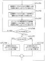
- FIG. 9 discloses the control of the control unit 10 based on the output average value b calculated in this way.
- a predetermined engine speed and load are detected during the stoichiometric operation, and the output target value a of the solenoid valve 21 set in the control unit 10 under these conditions is determined. Read (step 31).
- the output history of the pre-oxygen sensor 31 in the actual driving situation is traced back from the time when the output target value a is read, and the average value of the output history of the pre-oxygen sensor 31 over a fixed time is calculated as the output average value b.
- the maximum output value and the minimum output value of the pre-oxygen sensor 31 are measured retroactively for the past 10 cycles, and averaged to calculate the output average value b (step 32).
- Step 33 If the calorie of the fuel gas has not changed, the output target value a read in step 31 and the output average value b calculated in step 32 match, so the output target value a and the output average value b are compared. (Step 33).
- the calorie of the fuel gas is small by the difference, and the excess air ratio detected by the pre-oxygen sensor 31 starts to shift to the lean side.
- the A / F valve 22 is opened according to the rate (step 34).
- the calorie of the fuel gas is increased by the difference and the excess air ratio detected by the pre-oxygen sensor 31 starts to shift to the rich side.
- the A / F valve 22 is closed according to the rate. Further, when the output average value b is the same as the output target value a, the calorie of the fuel gas has not changed and the excess air ratio detected by the pre-oxygen sensor 31 has not deviated.
- the / F valve 22 maintains the opening (step 35).
- control unit 10 compares the output target value a obtained from the pre-oxygen sensor 31 and the output average value b to adjust the opening degree of the A / F valve 22.
- the output target value a obtained from the oxygen sensor 32 provided on the exhaust gas outlet side of the three-way catalyst 3b is compared with the output average value b to adjust the opening degree of the A / F valve 22. Also good.
- FIG. 10 shows a control flow of the control unit 10 when the output target value a obtained from the post oxygen sensor 32 is compared with the output average value b to adjust the opening degree of the A / F valve 22.
- a predetermined engine speed and load are detected during the stoichiometric operation, and the output target value a of the oxygen sensor 32 set in the control unit 10 is read under these conditions. (Step 41).
- the output history of the post-oxygen sensor 32 in the actual driving situation is traced back from the time when the output target value a is read, and the average value of the output history of the post-oxygen sensor 32 over a fixed time is calculated as the output average value b.
- the maximum output value and the minimum output value of the rear oxygen sensor 32 are measured retroactively for the past 10 cycles, and averaged to calculate the output average value b (step 42).
- Step 43 If the calorie of the fuel gas has not changed, the output target value a read in step 41 matches the output average value b calculated in step 42, so the output target value a and the output average value b are compared. (Step 43).
- the calorie of the fuel gas is small by the difference, and the excess air ratio detected by the post oxygen sensor 32 starts to shift to the lean side.
- the A / F valve 22 is opened according to the rate (step 44).
- the calorie of the fuel gas is larger by the difference, and the excess air ratio detected by the rear oxygen sensor 32 starts to shift to the rich side.
- the A / F valve 22 is closed according to the rate. Further, when the output average value b is the same as the output target value a, the calorie of the fuel gas has not changed and the excess air ratio detected by the post oxygen sensor 32 has not deviated.
- the / F valve 22 maintains the opening (step 45).
- step 41 Thereafter, the control from step 41 is repeated.
- the gas engine 1 adjusts the opening degree of the A / F valve 22 instead of the solenoid valve 21 when a fuel gas having a calorie lower or higher than the reference fuel gas is supplied. Therefore, even when the calorie of the fuel gas changes greatly, the perturbation control of the stoichiometric operation by the solenoid valve 21 can be continuously performed in response to the change.
- the air-fuel ratio control can be performed by calculating the output average value b without imposing a burden on the information processing of the control unit 10.
- the output average value b is calculated by measuring the maximum output value and the minimum output value retroactively for the past 10 cycles and averaging them (step). 32, step 42), and in particular, is not limited to calculating the output average value b based on the output history for 10 cycles, but appropriately changed according to the gas engine 1 to be used and its installation environment. It may be.
- the output target value a and the output average value b are compared, and the A / F valve 22 is controlled according to a predetermined rate by the difference, but the output It is difficult for the target value a and the output average value b to completely match. Therefore, in the case of the above control, the A / F valve 22 is frequently opened and closed repeatedly, and there is a concern that the burden on the control unit 10 will increase. Therefore, as shown in FIG. 11, together with each output target value a mapped to the control unit 10, a dead band width c corresponding to the output target value a is input and set in the control unit 10, and this dead band width c is set. You may control using.
- the dead band width c is a value that is set so that the A / F valve 22 does not frequently open and close in response to the difference between the output target value a and the output average value b. Otherwise, the numerical value range is set so that the opening degree of the A / F valve 22 is not changed. Therefore, the dead zone width c is appropriately set according to the gas engine 1 to be used and its use environment.
- FIG. 11 shows a control flow of the control unit 10 when the output target value a obtained from the pre-oxygen sensor 31 and the output average value b are compared to adjust the opening degree of the A / F valve 22. That is, in order to grasp the calorie change of the fuel gas, first, a predetermined engine speed and load are detected during the stoichiometric operation, and the output target value a of the pre-oxygen sensor 31 set in the control unit 10 under these conditions. Is read (step 51).
- the opening history of the pre-oxygen sensor 31 in the actual operating condition is traced back in the past, and the average value of the output history of the pre-oxygen sensor 31 over a certain time is calculated as the output average value b (step 52).
- the dead zone width c within the period when the engine speed and the load are constant, which is the same as when the output target value a is read, is read from the control unit 10 (step 53).
- the difference between the output target value a read in step 51 and the output average value b calculated in step 52 should be smaller than the dead zone width c.
- ) from the average value b is compared with the dead zone width c (step 54).
- the calorie of the fuel gas is small by the difference, and the excess air ratio detected by the pre-oxygen sensor 31 starts to shift to the lean side.
- the A / F valve 22 is opened according to the rate (step 56).
- the calorie of the fuel gas is increased by the difference and the excess air ratio detected by the pre-oxygen sensor 31 starts to shift to the rich side.
- the A / F valve 22 is closed according to the rate. Further, when the output average value b is the same as the output target value a, the calorie of the fuel gas has not changed and the excess air ratio detected by the pre-oxygen sensor 31 has not deviated.
- the / F valve 22 maintains the opening (step 57).
- step 51 Thereafter, the control from step 51 is repeated.
- control unit 10 compares the output target value a obtained from the pre-oxygen sensor 31 and the output average value b to adjust the opening degree of the A / F valve 22.
- the output target value a obtained from the oxygen sensor 32 provided on the exhaust gas outlet side of the three-way catalyst 3b is compared with the output average value b to adjust the opening degree of the A / F valve 22. Also good.
- FIG. 12 shows a control flow of the control unit 10 when the output target value a obtained from the rear oxygen sensor 32 and the output average value b are compared to adjust the opening degree of the A / F valve 22. That is, in order to grasp the calorie change of the fuel gas, first, a predetermined engine speed and load are detected during the stoichiometric operation, and the output target value a of the rear oxygen sensor 32 set in the control unit 10 under these conditions. Is read (step 61).
- the opening history of the rear oxygen sensor 32 in the actual driving situation is traced back in the past, and the average value of the output history of the rear oxygen sensor 32 over a certain time is calculated as the output average value b (step) 62).
- the dead zone width c is read from the control unit 10 within the same period when the engine speed and load are constant as when the output target value a is read (step 63).
- the difference between the output target value a read in step 61 and the output average value b calculated in step 62 should be smaller than the dead band width c.
- ) from the average value b is compared with the dead zone width c (step 64).
- the calorie of the fuel gas is small by the difference, and the excess air ratio detected by the post oxygen sensor 32 starts to shift to the lean side.
- the A / F valve 22 is opened according to the rate (step 66).
- the calorie of the fuel gas is larger by the difference, and the excess air ratio detected by the rear oxygen sensor 32 starts to shift to the rich side.
- the A / F valve 22 is closed according to the rate. Further, when the output average value b is the same as the output target value a, the calorie of the fuel gas has not changed and the excess air ratio detected by the post oxygen sensor 32 has not deviated.
- the / F valve 22 maintains the opening (step 67).
- step 61 Thereafter, the control from step 61 is repeated.
- the gas engine 1 adjusts the opening degree of the A / F valve 22 instead of the solenoid valve 21 when fuel gas having a calorie lower or higher than the reference fuel gas is supplied. Therefore, even when the calorie of the fuel gas changes greatly, the perturbation control of the stoichiometric operation by the solenoid valve 21 can be continuously performed in response to the change.
- the dead zone width c By providing the dead zone width c and controlling it, it is possible to prevent the A / F valve 22 from frequently opening and closing in response to the difference between the output target value a and the output average value b, and to control the control.
- the burden of information processing by the unit 10 can be reduced. Therefore, the air-fuel ratio control can be stabilized by preventing unintentional hunting of the air-fuel ratio.
- FIGS. 11 and 12 The control shown in FIGS. 11 and 12 has been described for the case where the dead zone width c is incorporated into the control shown in FIGS. 6 and 7. However, the dead zone width c is incorporated into the control shown in FIGS. It is also possible to perform control.
- one mixing section 2a is provided in the intake passage 12, but one mixing section 2a is provided in each cylinder head 11 of the gas engine 1 as shown in FIG.
- one unit may be provided for every two or more cylinder heads 11 (two in the drawing).
- the mixing unit 2a is configured to control the solenoid valve 21 and the A / F valve 22 having different flow characteristics.
- the flow rate adjusting valve 20 may be configured to be controlled by providing two or a plurality of three or more (three in the drawing).
- the fuel flow rate adjustment valve 20 that operates in the same manner as the solenoid valve 21 in the present embodiment and the fuel flow rate adjustment valve 20 that operates in the same manner as the A / F valve 22 are provided.
- each fuel flow rate adjustment valve 20 is configured to operate in the same manner as the solenoid valve 21 in the present embodiment and to operate in the same manner as the A / F valve 22. May be.
- various types of valves used for this type of fuel gas control such as butterfly valves and solenoid valves, can be used as the fuel flow rate adjusting valve 20.
- the gas engine 1 is configured to be able to switch between stoichiometric operation and lean operation, but may be a gas engine 1 configured to perform only stoichiometric operation.
- the gas engine 1 is configured to detect the excess air ratio of the stoichiometric operation by the pre-oxygen sensor 31, but instead of the pre-oxygen sensor 31, the full-range sensor (not shown) is used for the stoichiometric operation. It may be configured to detect an excess air ratio.
- Each gas engine 1 configured as described above can be suitably used as a drive source of the gas heat pump device 4 as shown in FIG. Moreover, this gas engine 1 can be used suitably also as a drive source of the cogeneration apparatus 5, as shown in FIG.
- these devices often operate for a long period of time without being stopped, or use fuel gas generated using biomass that tends to cause a change in composition. There are many factors that are likely to occur. Therefore, these devices make it easier to take advantage of the effects of the present invention by using the gas engine 1 of the present invention that can cope with the calorie change of the fuel gas.
- the gas heat pump device 4 has two compressors 41 connected to the gas engine 1, but the number of compressors 41 may be one or three or more.
- the gas heat pump device 4 has two indoor units 43 connected to one outdoor unit 42, but the indoor unit 43 may be one unit or three or more units. There may be.
- the gas engine 1 is described.
- the present invention may be applied to various encines in which perturbation control is performed.
Landscapes
- Engineering & Computer Science (AREA)
- Chemical & Material Sciences (AREA)
- Combustion & Propulsion (AREA)
- Mechanical Engineering (AREA)
- General Engineering & Computer Science (AREA)
- Chemical Kinetics & Catalysis (AREA)
- General Chemical & Material Sciences (AREA)
- Oil, Petroleum & Natural Gas (AREA)
- Electrical Control Of Air Or Fuel Supplied To Internal-Combustion Engine (AREA)
- Output Control And Ontrol Of Special Type Engine (AREA)
- Combined Controls Of Internal Combustion Engines (AREA)
Abstract
Description
れている。
10 制御部
11 シリンダヘッド
13 排気経路
2 吸気部
20 燃料流量調整バルブ(第一バルブおよび/まはた第二バルブ)
21 ソレノイドバルブ(第二バルブ)
22 A/Fバルブ(第一バルブ)
31 前酸素センサ
32 後酸素センサ
a 出力目標値
b 出力平均値
Claims (10)
- 第二バルブよりも応答性が低く燃料流量調整幅が大きい第一バルブと、第一バルブよりも応答性が高く燃料流量調整幅が小さい第二バルブとを具備し、
第一バルブを所定の開度に開けた状態で、第二バルブを所定の開度からリーン側およびリッチ側に変動させて、当該第二バルブによるパータベーションを行うように構成された制御部を備えており、
当該制御部は、ガスエンジンの運転状況が一定だとみなされる期間内における実際の運転時に、ガスエンジンの排気経路に設けられた酸素センサから得られる出力の平均値が、当該条件で制御部に設定されている酸素センサの出力目標値から外れている場合に、出力平均値が出力目標値となるように第一バルブの開度を調整するようになされたことを特徴とするガスエンジン。 - 制御部は、実際の運転時の第二バルブによるパータベーション制御における最大開度と最小開度とに対応した、酸素センサの最大出力と最小出力とを抽出して出力平均値を算出するものである請求項1記載のガスエンジン。
- 制御部は、幅を持たせた出力目標値に収束するように第一バルブの開度を調整するものである請求項1記載のガスエンジン。
- 制御部は、幅を持たせた出力目標値に収束するように第一バルブの開度を調整するものである請求項2記載のガスエンジン。
- 第一バルブおよび第二バルブは、各シリンダヘッド毎または複数のシリンダヘッダ毎に設けられたことを特徴とする請求項1ないし4の何れか一に記載のガスエンジン。
- 第一バルブおよび/または第二バルブが複数設けられたことを特徴とする請求項1ないし4の何れか一に記載のガスエンジン。
- 酸素センサは、排気経路の触媒上流側に設けられた前酸素センサとなされた請求項1ないし4の何れか一に記載のガスエンジン。
- 酸素センサは、排気経路の触媒下流側に設けられた後酸素センサとなされた請求項1ないし4の何れか一に記載のガスエンジン。
- 請求項1ないし4の何れか一に記載のガスエンジンを駆動源とするガスヒートポンプ装置。
- 請求項1ないし4の何れか一に記載のガスエンジンを駆動源とするコージェネレーション装置。
Priority Applications (6)
| Application Number | Priority Date | Filing Date | Title |
|---|---|---|---|
| EP14810819.4A EP2993334B1 (en) | 2013-06-11 | 2014-05-28 | Gas engine |
| KR1020157034085A KR102011552B1 (ko) | 2013-06-11 | 2014-05-28 | 가스 엔진 |
| CN201480032877.7A CN105283653B (zh) | 2013-06-11 | 2014-05-28 | 燃气发动机 |
| AU2014279324A AU2014279324A1 (en) | 2013-06-11 | 2014-05-28 | Gas engine |
| US14/897,005 US10539089B2 (en) | 2013-06-11 | 2014-05-28 | Gas engine |
| CA2914973A CA2914973A1 (en) | 2013-06-11 | 2014-05-28 | Gas engine |
Applications Claiming Priority (2)
| Application Number | Priority Date | Filing Date | Title |
|---|---|---|---|
| JP2013-122700 | 2013-06-11 | ||
| JP2013122700A JP6134587B2 (ja) | 2013-06-11 | 2013-06-11 | ガスエンジン |
Publications (1)
| Publication Number | Publication Date |
|---|---|
| WO2014199828A1 true WO2014199828A1 (ja) | 2014-12-18 |
Family
ID=52022127
Family Applications (1)
| Application Number | Title | Priority Date | Filing Date |
|---|---|---|---|
| PCT/JP2014/064114 Ceased WO2014199828A1 (ja) | 2013-06-11 | 2014-05-28 | ガスエンジン |
Country Status (8)
| Country | Link |
|---|---|
| US (1) | US10539089B2 (ja) |
| EP (1) | EP2993334B1 (ja) |
| JP (1) | JP6134587B2 (ja) |
| KR (1) | KR102011552B1 (ja) |
| CN (1) | CN105283653B (ja) |
| AU (1) | AU2014279324A1 (ja) |
| CA (1) | CA2914973A1 (ja) |
| WO (1) | WO2014199828A1 (ja) |
Cited By (1)
| Publication number | Priority date | Publication date | Assignee | Title |
|---|---|---|---|---|
| WO2017011163A1 (en) * | 2015-07-10 | 2017-01-19 | General Electric Company | Dual fuel system for a combustion engine |
Families Citing this family (5)
| Publication number | Priority date | Publication date | Assignee | Title |
|---|---|---|---|---|
| JP6482946B2 (ja) * | 2015-05-14 | 2019-03-13 | ヤンマー株式会社 | ガスエンジン |
| JP6047217B1 (ja) * | 2015-11-10 | 2016-12-21 | 川崎重工業株式会社 | ガスエンジン駆動システム |
| US10914246B2 (en) | 2017-03-14 | 2021-02-09 | General Electric Company | Air-fuel ratio regulation for internal combustion engines |
| JP6439207B1 (ja) * | 2018-06-29 | 2018-12-19 | 三菱重工環境・化学エンジニアリング株式会社 | 排ガス水銀除去システム |
| KR20210071461A (ko) | 2019-12-06 | 2021-06-16 | 엘지전자 주식회사 | 가스 히트펌프 시스템 |
Citations (5)
| Publication number | Priority date | Publication date | Assignee | Title |
|---|---|---|---|---|
| JPS61255229A (ja) * | 1985-05-07 | 1986-11-12 | Yanmar Diesel Engine Co Ltd | ガス機関の出力制御装置 |
| JPH01113565A (ja) * | 1987-10-27 | 1989-05-02 | Yanmar Diesel Engine Co Ltd | 火花点火機関の空燃比制御装置 |
| JP2000282914A (ja) * | 1999-03-31 | 2000-10-10 | Yanmar Diesel Engine Co Ltd | 内燃機関の空燃比制御装置 |
| JP2003148187A (ja) | 2001-11-12 | 2003-05-21 | Tokyo Gas Co Ltd | 内燃機関の制御装置及び制御方法 |
| JP2008038729A (ja) * | 2006-08-04 | 2008-02-21 | Yanmar Co Ltd | ガスエンジンの制御方法 |
Family Cites Families (30)
| Publication number | Priority date | Publication date | Assignee | Title |
|---|---|---|---|---|
| CH671609A5 (de) * | 1985-06-24 | 1989-09-15 | Mitsui Shipbuilding Eng | Vorrichtung zum verhindern eines uebermaessigen durchflusses von gasfoermigem brennstoff durch eine einspritzduese eines dieselmotors. |
| US5186137A (en) * | 1987-02-27 | 1993-02-16 | Salzmann Willy E | Rocking-piston machine |
| US5230321A (en) * | 1992-07-21 | 1993-07-27 | Gas Research Institute | Lean-burn internal combustion gas engine |
| US5363831A (en) * | 1993-11-16 | 1994-11-15 | Unisia Jecs Corporation | Method of and an apparatus for carrying out feedback control on an air-fuel ratio in an internal combustion engine |
| KR100222527B1 (ko) * | 1994-11-24 | 1999-10-01 | 정몽규 | 내연기관의 흡기조절장치 |
| JPH11200845A (ja) * | 1998-01-06 | 1999-07-27 | Nissan Motor Co Ltd | 触媒の劣化検出装置 |
| US6253744B1 (en) * | 1999-03-19 | 2001-07-03 | Unisia Jecs Corporation | Method and apparatus for controlling fuel vapor, method and apparatus for diagnosing fuel vapor control apparatus, and method and apparatus for controlling air-fuel ratio |
| JP3680217B2 (ja) * | 2000-06-26 | 2005-08-10 | トヨタ自動車株式会社 | 内燃機関の空燃比制御装置 |
| US6681564B2 (en) * | 2001-02-05 | 2004-01-27 | Komatsu Ltd. | Exhaust gas deNOx apparatus for engine |
| JP2003262139A (ja) * | 2002-03-08 | 2003-09-19 | Mitsubishi Heavy Ind Ltd | ガスエンジンの空燃比制御方法及びその装置 |
| US6752135B2 (en) * | 2002-11-12 | 2004-06-22 | Woodward Governor Company | Apparatus for air/fuel ratio control |
| JP2006322403A (ja) | 2005-05-19 | 2006-11-30 | Toyota Industries Corp | 内燃機関のガス燃料供給装置及び供給制御方法 |
| JP2007239698A (ja) | 2006-03-10 | 2007-09-20 | Toyota Motor Corp | 内燃機関の空燃比制御装置 |
| JP2008038782A (ja) * | 2006-08-07 | 2008-02-21 | Yanmar Co Ltd | エンジン駆動式ヒートポンプのエンスト防止制御装置 |
| JP4616878B2 (ja) * | 2007-12-14 | 2011-01-19 | 三菱重工業株式会社 | ガスエンジンシステムの制御方法及び該システム |
| JP4563443B2 (ja) * | 2007-12-14 | 2010-10-13 | 三菱重工業株式会社 | ガスエンジンシステムの制御方法及び該システム |
| KR101324900B1 (ko) * | 2008-10-01 | 2013-11-04 | 미츠비시 쥬고교 가부시키가이샤 | 가스 터빈 장치 |
| JP2011012593A (ja) * | 2009-07-01 | 2011-01-20 | Hitachi Automotive Systems Ltd | 内燃機関の制御装置 |
| US8336300B2 (en) * | 2009-09-29 | 2012-12-25 | Ford Global Technologies, Llc | System and method for regenerating a particulate filter accompanied by a catalyst |
| JP4977752B2 (ja) * | 2009-12-24 | 2012-07-18 | 川崎重工業株式会社 | ガスエンジンの制御装置及び制御方法 |
| DE102010014843B4 (de) * | 2010-04-13 | 2020-06-25 | Pierburg Gmbh | Abgaskühlmodul für eine Verbrennungskraftmaschine |
| JP5667413B2 (ja) * | 2010-10-22 | 2015-02-12 | ヤンマー株式会社 | エンジン制御方法 |
| JP2012154276A (ja) | 2011-01-27 | 2012-08-16 | Honda Motor Co Ltd | 制御装置及び同装置を備えたコージェネレーション装置 |
| JP5308466B2 (ja) * | 2011-01-31 | 2013-10-09 | 三菱重工業株式会社 | ガスエンジンの燃料ガス供給方法および装置 |
| JP5615872B2 (ja) | 2012-06-12 | 2014-10-29 | 日立オートモティブシステムズ株式会社 | 内燃機関の制御装置 |
| US9151249B2 (en) * | 2012-09-24 | 2015-10-06 | Elwha Llc | System and method for storing and dispensing fuel and ballast fluid |
| JP6014474B2 (ja) * | 2012-11-30 | 2016-10-25 | ヤンマー株式会社 | ガスエンジン |
| JP6128975B2 (ja) * | 2013-06-11 | 2017-05-17 | ヤンマー株式会社 | ガスエンジン |
| CN105556968B (zh) * | 2014-06-23 | 2018-09-04 | 联发科技(新加坡)私人有限公司 | 三维或多视图视频编码系统中预测编码的装置及方法 |
| JP6482946B2 (ja) * | 2015-05-14 | 2019-03-13 | ヤンマー株式会社 | ガスエンジン |
-
2013
- 2013-06-11 JP JP2013122700A patent/JP6134587B2/ja not_active Expired - Fee Related
-
2014
- 2014-05-28 KR KR1020157034085A patent/KR102011552B1/ko active Active
- 2014-05-28 EP EP14810819.4A patent/EP2993334B1/en not_active Not-in-force
- 2014-05-28 CA CA2914973A patent/CA2914973A1/en not_active Abandoned
- 2014-05-28 WO PCT/JP2014/064114 patent/WO2014199828A1/ja not_active Ceased
- 2014-05-28 US US14/897,005 patent/US10539089B2/en not_active Expired - Fee Related
- 2014-05-28 CN CN201480032877.7A patent/CN105283653B/zh not_active Expired - Fee Related
- 2014-05-28 AU AU2014279324A patent/AU2014279324A1/en not_active Abandoned
Patent Citations (5)
| Publication number | Priority date | Publication date | Assignee | Title |
|---|---|---|---|---|
| JPS61255229A (ja) * | 1985-05-07 | 1986-11-12 | Yanmar Diesel Engine Co Ltd | ガス機関の出力制御装置 |
| JPH01113565A (ja) * | 1987-10-27 | 1989-05-02 | Yanmar Diesel Engine Co Ltd | 火花点火機関の空燃比制御装置 |
| JP2000282914A (ja) * | 1999-03-31 | 2000-10-10 | Yanmar Diesel Engine Co Ltd | 内燃機関の空燃比制御装置 |
| JP2003148187A (ja) | 2001-11-12 | 2003-05-21 | Tokyo Gas Co Ltd | 内燃機関の制御装置及び制御方法 |
| JP2008038729A (ja) * | 2006-08-04 | 2008-02-21 | Yanmar Co Ltd | ガスエンジンの制御方法 |
Non-Patent Citations (1)
| Title |
|---|
| See also references of EP2993334A4 |
Cited By (1)
| Publication number | Priority date | Publication date | Assignee | Title |
|---|---|---|---|---|
| WO2017011163A1 (en) * | 2015-07-10 | 2017-01-19 | General Electric Company | Dual fuel system for a combustion engine |
Also Published As
| Publication number | Publication date |
|---|---|
| US20160123266A1 (en) | 2016-05-05 |
| KR102011552B1 (ko) | 2019-08-16 |
| CN105283653B (zh) | 2018-02-23 |
| EP2993334A1 (en) | 2016-03-09 |
| US10539089B2 (en) | 2020-01-21 |
| EP2993334B1 (en) | 2018-03-28 |
| KR20160018502A (ko) | 2016-02-17 |
| AU2014279324A2 (en) | 2016-03-03 |
| JP6134587B2 (ja) | 2017-05-24 |
| AU2014279324A1 (en) | 2016-01-28 |
| JP2014240615A (ja) | 2014-12-25 |
| CN105283653A (zh) | 2016-01-27 |
| CA2914973A1 (en) | 2014-12-18 |
| EP2993334A4 (en) | 2016-05-04 |
Similar Documents
| Publication | Publication Date | Title |
|---|---|---|
| JP6128975B2 (ja) | ガスエンジン | |
| JP6014474B2 (ja) | ガスエンジン | |
| JP6134587B2 (ja) | ガスエンジン | |
| JP6482946B2 (ja) | ガスエンジン | |
| EP2899386B1 (en) | Internal combustion engine | |
| KR20140071451A (ko) | 가스 엔진, 가스 엔진을 이용한 가스 히트 펌프 장치 및 코제너레이션 장치, 그리고 가스 엔진의 제어 방법 |
Legal Events
| Date | Code | Title | Description |
|---|---|---|---|
| WWE | Wipo information: entry into national phase |
Ref document number: 201480032877.7 Country of ref document: CN |
|
| 121 | Ep: the epo has been informed by wipo that ep was designated in this application |
Ref document number: 14810819 Country of ref document: EP Kind code of ref document: A1 |
|
| ENP | Entry into the national phase |
Ref document number: 20157034085 Country of ref document: KR Kind code of ref document: A |
|
| WWE | Wipo information: entry into national phase |
Ref document number: 2014810819 Country of ref document: EP |
|
| ENP | Entry into the national phase |
Ref document number: 2914973 Country of ref document: CA |
|
| WWE | Wipo information: entry into national phase |
Ref document number: 14897005 Country of ref document: US |
|
| NENP | Non-entry into the national phase |
Ref country code: DE |
|
| ENP | Entry into the national phase |
Ref document number: 2014279324 Country of ref document: AU Date of ref document: 20140528 Kind code of ref document: A |