WO2014199838A1 - 固体撮像装置 - Google Patents
固体撮像装置 Download PDFInfo
- Publication number
- WO2014199838A1 WO2014199838A1 PCT/JP2014/064319 JP2014064319W WO2014199838A1 WO 2014199838 A1 WO2014199838 A1 WO 2014199838A1 JP 2014064319 W JP2014064319 W JP 2014064319W WO 2014199838 A1 WO2014199838 A1 WO 2014199838A1
- Authority
- WO
- WIPO (PCT)
- Prior art keywords
- photodiode
- imaging device
- light receiving
- solid
- row
- Prior art date
- Legal status (The legal status is an assumption and is not a legal conclusion. Google has not performed a legal analysis and makes no representation as to the accuracy of the status listed.)
- Ceased
Links
Images




Classifications
-
- H—ELECTRICITY
- H04—ELECTRIC COMMUNICATION TECHNIQUE
- H04N—PICTORIAL COMMUNICATION, e.g. TELEVISION
- H04N25/00—Circuitry of solid-state image sensors [SSIS]; Control thereof
- H04N25/70—SSIS architectures; Circuits associated therewith
- H04N25/71—Charge-coupled device [CCD] sensors; Charge-transfer registers specially adapted for CCD sensors
-
- H—ELECTRICITY
- H10—SEMICONDUCTOR DEVICES; ELECTRIC SOLID-STATE DEVICES NOT OTHERWISE PROVIDED FOR
- H10F—INORGANIC SEMICONDUCTOR DEVICES SENSITIVE TO INFRARED RADIATION, LIGHT, ELECTROMAGNETIC RADIATION OF SHORTER WAVELENGTH OR CORPUSCULAR RADIATION
- H10F39/00—Integrated devices, or assemblies of multiple devices, comprising at least one element covered by group H10F30/00, e.g. radiation detectors comprising photodiode arrays
- H10F39/80—Constructional details of image sensors
- H10F39/802—Geometry or disposition of elements in pixels, e.g. address-lines or gate electrodes
-
- H—ELECTRICITY
- H04—ELECTRIC COMMUNICATION TECHNIQUE
- H04N—PICTORIAL COMMUNICATION, e.g. TELEVISION
- H04N25/00—Circuitry of solid-state image sensors [SSIS]; Control thereof
- H04N25/60—Noise processing, e.g. detecting, correcting, reducing or removing noise
- H04N25/67—Noise processing, e.g. detecting, correcting, reducing or removing noise applied to fixed-pattern noise, e.g. non-uniformity of response
- H04N25/671—Noise processing, e.g. detecting, correcting, reducing or removing noise applied to fixed-pattern noise, e.g. non-uniformity of response for non-uniformity detection or correction
-
- H—ELECTRICITY
- H04—ELECTRIC COMMUNICATION TECHNIQUE
- H04N—PICTORIAL COMMUNICATION, e.g. TELEVISION
- H04N25/00—Circuitry of solid-state image sensors [SSIS]; Control thereof
- H04N25/60—Noise processing, e.g. detecting, correcting, reducing or removing noise
- H04N25/67—Noise processing, e.g. detecting, correcting, reducing or removing noise applied to fixed-pattern noise, e.g. non-uniformity of response
- H04N25/671—Noise processing, e.g. detecting, correcting, reducing or removing noise applied to fixed-pattern noise, e.g. non-uniformity of response for non-uniformity detection or correction
- H04N25/673—Noise processing, e.g. detecting, correcting, reducing or removing noise applied to fixed-pattern noise, e.g. non-uniformity of response for non-uniformity detection or correction by using reference sources
-
- H—ELECTRICITY
- H04—ELECTRIC COMMUNICATION TECHNIQUE
- H04N—PICTORIAL COMMUNICATION, e.g. TELEVISION
- H04N25/00—Circuitry of solid-state image sensors [SSIS]; Control thereof
- H04N25/70—SSIS architectures; Circuits associated therewith
- H04N25/76—Addressed sensors, e.g. MOS or CMOS sensors
-
- H—ELECTRICITY
- H10—SEMICONDUCTOR DEVICES; ELECTRIC SOLID-STATE DEVICES NOT OTHERWISE PROVIDED FOR
- H10F—INORGANIC SEMICONDUCTOR DEVICES SENSITIVE TO INFRARED RADIATION, LIGHT, ELECTROMAGNETIC RADIATION OF SHORTER WAVELENGTH OR CORPUSCULAR RADIATION
- H10F39/00—Integrated devices, or assemblies of multiple devices, comprising at least one element covered by group H10F30/00, e.g. radiation detectors comprising photodiode arrays
- H10F39/10—Integrated devices
- H10F39/12—Image sensors
-
- H—ELECTRICITY
- H10—SEMICONDUCTOR DEVICES; ELECTRIC SOLID-STATE DEVICES NOT OTHERWISE PROVIDED FOR
- H10F—INORGANIC SEMICONDUCTOR DEVICES SENSITIVE TO INFRARED RADIATION, LIGHT, ELECTROMAGNETIC RADIATION OF SHORTER WAVELENGTH OR CORPUSCULAR RADIATION
- H10F39/00—Integrated devices, or assemblies of multiple devices, comprising at least one element covered by group H10F30/00, e.g. radiation detectors comprising photodiode arrays
- H10F39/10—Integrated devices
- H10F39/12—Image sensors
- H10F39/18—Complementary metal-oxide-semiconductor [CMOS] image sensors; Photodiode array image sensors
- H10F39/189—X-ray, gamma-ray or corpuscular radiation imagers
- H10F39/1898—Indirect radiation image sensors, e.g. using luminescent members
-
- H—ELECTRICITY
- H10—SEMICONDUCTOR DEVICES; ELECTRIC SOLID-STATE DEVICES NOT OTHERWISE PROVIDED FOR
- H10F—INORGANIC SEMICONDUCTOR DEVICES SENSITIVE TO INFRARED RADIATION, LIGHT, ELECTROMAGNETIC RADIATION OF SHORTER WAVELENGTH OR CORPUSCULAR RADIATION
- H10F39/00—Integrated devices, or assemblies of multiple devices, comprising at least one element covered by group H10F30/00, e.g. radiation detectors comprising photodiode arrays
- H10F39/80—Constructional details of image sensors
- H10F39/803—Pixels having integrated switching, control, storage or amplification elements
-
- H—ELECTRICITY
- H04—ELECTRIC COMMUNICATION TECHNIQUE
- H04N—PICTORIAL COMMUNICATION, e.g. TELEVISION
- H04N25/00—Circuitry of solid-state image sensors [SSIS]; Control thereof
- H04N25/30—Circuitry of solid-state image sensors [SSIS]; Control thereof for transforming X-rays into image signals
-
- H—ELECTRICITY
- H04—ELECTRIC COMMUNICATION TECHNIQUE
- H04N—PICTORIAL COMMUNICATION, e.g. TELEVISION
- H04N25/00—Circuitry of solid-state image sensors [SSIS]; Control thereof
- H04N25/60—Noise processing, e.g. detecting, correcting, reducing or removing noise
- H04N25/62—Detection or reduction of noise due to excess charges produced by the exposure, e.g. smear, blooming, ghost image, crosstalk or leakage between pixels
- H04N25/628—Detection or reduction of noise due to excess charges produced by the exposure, e.g. smear, blooming, ghost image, crosstalk or leakage between pixels for reducing horizontal stripes caused by saturated regions of CMOS sensors
Definitions
- the present invention relates to a solid-state imaging device.
- Patent Document 1 describes a technique related to a radiation imaging apparatus.
- This apparatus includes a sensor array in which a plurality of pixels including a conversion element that converts radiation from a subject into an electric signal and a transfer switch that transfers the electric signal to the outside are two-dimensionally arranged.
- the device includes a plurality of gate lines that connect the pixels of the sensor array in the row direction, and a gate driving device that drives the gate lines to read out electrical signals of the pixels connected to the gate lines.
- the solid-state imaging device has a light receiving unit in which a plurality of pixels are arranged two-dimensionally over a plurality of rows and columns.
- Each pixel is provided with a photodiode for converting incident light into electrons.
- the photodiode of each pixel is connected to the readout wiring arranged for each column via a switch circuit (for example, a transistor), and the charge accumulated in the photodiode becomes conductive. This flows out to the readout wiring.
- the electric charge reaches the integrating circuit through the readout wiring and is converted into a voltage signal in the integrating circuit.
- a control terminal for example, a gate terminal
- a control terminal for controlling the conduction state of the switch circuit of each pixel is connected to a row selection wiring arranged for each row. Then, a signal from the shift register is supplied to the control terminal of each switch circuit via the row selection wiring, whereby the charge is read from each pixel for each row.
- the solid-state imaging device having such a configuration, light is incident not only on the light receiving unit but also on a region around the light receiving unit.
- a solid-state imaging device is used as an X-ray imaging device
- X-rays transmitted through the scintillator and scintillation light from the scintillator are transmitted to the light receiving unit even if the area around the light receiving unit is covered with the scintillator. Incident into the surrounding area.
- unnecessary charges (carriers) are generated in the region around the light receiving unit.
- the shift register arranged alongside the light receiving portion has a certain area, many unnecessary carriers are generated in the region where the shift register is formed.
- a photodiode for absorbing unnecessary carriers is arranged in a region between the shift register and the light receiving unit, and this dummy photodiode is connected to a reference potential line (ground wiring).
- this method has the following problems.
- crosstalk caused by coupling capacitance or the like generated between these photodiodes exists between pixels adjacent to each other in the light receiving section.
- a parasitic capacitance exists between the photodiode and the row selection wiring connected to each other via the switch circuit, and this parasitic capacitance also affects the crosstalk.
- the dummy photodiode described above is not provided with a switch circuit, such a parasitic capacitance does not occur. For this reason, the pixel adjacent to the dummy photodiode has a different degree of crosstalk compared to the other pixels, and the output characteristics and noise level from the pixel adjacent to the dummy photodiode are different from those of the other pixels. End up.
- the present invention has been made in view of such problems, and provides a solid-state imaging device capable of bringing the output characteristics and noise magnitude of pixels adjacent to a dummy photodiode closer to other pixels. With the goal.
- a solid-state imaging device includes a first photodiode and a first switch circuit having one end connected to the first photodiode, and includes M rows and N columns ( M, N are integers of 2 or more) and a light receiving unit having M ⁇ N pixels arranged two-dimensionally, and a first switch circuit arranged for each column and included in the corresponding column of pixels N readout wirings connected to the ends, a readout circuit unit connected to the N readout wirings, and arranged in the row direction with respect to the light receiving unit, the open / close state of the first switch circuit
- M dummy photodiodes are arranged for each row in a region between the shift register and the light receiving unit. Unnecessary carriers generated in the shift register are absorbed by the dummy photodiode. As a result, it is possible to effectively prevent noise caused by unnecessary carriers generated in the shift register from being superimposed on the output from the pixels of the light receiving unit.
- the dummy photodiode and the charge discharging wiring are connected via the second switch circuit, and when the second switch circuit is turned on, the unnecessary carrier is a dummy photo. It is discharged from the diode to the reference potential line through the charge discharging wiring.
- the second switch circuit is provided in the dummy photodiode as well as the first switch circuit in each pixel in the light receiving unit.
- the magnitude of the crosstalk in the pixels adjacent to the dummy photodiode can be made closer to the magnitude of the crosstalk in the other pixels, It becomes possible to bring the output characteristics and the magnitude of noise close to those of other pixels.
- the output characteristics and noise level of the pixels adjacent to the dummy photodiode can be brought close to other pixels.
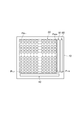
- FIG. 1 is a plan view showing a solid-state imaging device.
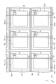
- FIG. 2 is an enlarged plan view of a part of the solid-state imaging device.
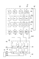
- FIG. 3 is a diagram illustrating an internal configuration of the solid-state imaging device.
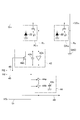
- FIG. 4 is a diagram illustrating a detailed circuit configuration example of the pixel, the integration circuit, the holding circuit, and the carrier capture region.
- FIG. 5 is a timing chart of each signal.
- FIG. 6 is a plan view showing an example in which dummy photodiodes for absorbing unnecessary carriers are arranged in a region between the shift register and the light receiving unit.
- FIG. 7A is a plan view of the light receiving unit, showing an example of a boundary line for joint exposure, and FIG.
- FIG. 7B is a diagram showing an example of a boundary line for joint exposure near the carrier capture unit.
- FIG. 8A is a plan view of the light receiving unit, showing another example of a boundary line for joint exposure
- FIG. 8B is a diagram showing another example of a boundary line for joint exposure in the vicinity of the carrier capturing unit. It is.
- FIG. 9 is a plan view schematically showing an example in which two glass substrates are arranged side by side.
- the solid-state imaging device according to the present embodiment is used in, for example, a medical X-ray imaging system.
- 1 and 2 are diagrams showing a configuration of a solid-state imaging device 1A according to the present embodiment.
- FIG. 1 is a plan view showing the solid-state imaging device 1A
- FIG. 2 is an enlarged plan view of a part of the solid-state imaging device 1A.
- 1 and 2 also show the XYZ orthogonal coordinate system for easy understanding.
- the solid-state imaging device 1 ⁇ / b> A includes a light receiving unit 20, an unnecessary carrier capturing unit 30, a reading circuit unit 40, and a vertical shift register 60.
- the light receiving unit 20, the unnecessary carrier capturing unit 30, the reading circuit unit 40, and the vertical shift register 60 are fabricated on the main surface of the substrate 12.
- the vertical shift register 60 is arranged side by side with respect to the light receiving unit 20 in the X-axis direction.
- a part of the unnecessary carrier capturing unit 30 is disposed in a region between the light receiving unit 20 and the vertical shift register 60, and the remaining part of the unnecessary carrier capturing unit 30 is aligned with the light receiving unit 20 in the Y-axis direction. And is located in a region between the light receiving unit 20 and the readout circuit unit 40.
- the readout circuit unit 40 includes a plurality of integration circuits provided corresponding to each of the plurality of columns of the light receiving unit 20, and the plurality of integration circuits correspond to the amount of charge output from the pixels in the corresponding column. Each voltage value is generated.
- the read circuit unit 40 holds the voltage value output from each integrating circuit, and sequentially outputs the held voltage value.
- the light receiving unit 20 is configured by two-dimensionally arranging a plurality of pixels P 1,1 to P M, N over M rows and N columns (M and N are integers of 2 or more).
- M and N are integers of 2 or more.
- four pixels P m, N ⁇ 1 , P m, N , P m + 1, N ⁇ 1 and P m + 1, N are represented on behalf of the plurality of pixels P 1,1 to P M, N. It is shown.
- the pixel P m, N is a pixel located in the m-th row and the N-th column (m is an integer of 1 to M). 1 and 2, the column direction matches the Y-axis direction, and the row direction matches the X-axis direction.
- Each of the pixels P 1,1 to P M, N included in the light receiving unit 20 includes a transistor 21 and a photodiode 22.
- the transistor 21 included in each of the pixels P 1,1 to P M, N is the first switch circuit in the present embodiment.
- the transistor 21 is preferably a field effect transistor (FET), but may be a bipolar transistor. In the following description, it is assumed that the transistor 21 is an FET. In this case, the control terminal means a gate. When the transistor 21 is a bipolar transistor, the control terminal means a base.
- the photodiode 22 included in each of the pixels P 1,1 to P M, N is the first photodiode in the present embodiment.
- the photodiode 22 is constituted by a semiconductor region including a pn junction or a pin junction, generates an amount of electric charge corresponding to the incident light intensity, and accumulates the generated electric charge in the junction capacitance portion.
- One end (for example, a source region) of the transistor 21 is electrically connected to the photodiode 22.
- a scintillator (not shown) is provided on the light receiving unit 20. The scintillator generates scintillation light according to the incident X-rays, converts the X-ray image into an optical image, and outputs this optical image to the photodiode 22.
- the solid-state imaging device 1A is provided with a plurality of row selection wirings Q 1 to Q M (shown as representative of Q m and Q m + 1 in FIG. 2) arranged for each row and for each column.
- a plurality of readout wirings R 1 to R N (representing RN and R N-1 as representative in FIG. 2) are further provided.
- the m-th row selection wiring Q m includes a control terminal (for example, a gate terminal) for controlling the open / close state of the transistors 21 included in the pixels P m, 1 to P m, N of the corresponding row, and the transistor 21.
- a control terminal for example, a gate terminal
- the readout wiring R n in the n-th column is the other end (for example, drain region) of the transistor 21 included in the pixels P 1, n to P M, n of the corresponding column. And are electrically connected.
- the plurality of row selection wirings Q 1 to Q M and the plurality of readout wirings R 1 to R N are made of metal, for example.
- Unnecessary carrier capturing portion 30 has M carrier capturing regions DA 1 ⁇ DA M.
- Carrier capturing regions DA 1 ⁇ DA M is in the region between the light receiving portion 20 and the vertical shift register 60, are arranged in each row.
- FIG. 2 on behalf of the carrier capture region DA 1 ⁇ DA M, 2 one carrier capture region DA m and DA m + 1 is shown.
- the carrier trap region DA m is a carrier trap region located in the m-th row.
- Each of the M carrier capture regions DA 1 to DA M includes a transistor 21 and a photodiode 22 in the same manner as the pixels P 1,1 to P M, N described above.
- the M transistors 21 included in each of the carrier trap regions DA 1 to DA M are the second switch circuit in the present embodiment.
- the M photodiodes 22 included in each of the carrier capture regions DA 1 to DA M are dummy photodiodes in the present embodiment, are configured by a semiconductor region including a pn junction or a pin junction, and are perpendicular to the light receiving unit 20. It is arranged for each row in the area between the shift register 60. One end (for example, a source region) of the transistor 21 is electrically connected to the photodiode 22.
- Carrier control terminal for controlling the opening and closing states of the capture region transistor 21 included in the DA m is the corresponding row selecting wiring Q m and electrically connected to the line.
- the solid-state imaging device 1A further includes a charge discharging wiring Rd .
- Charge discharging wire R d is, the other end of the transistor 21 included in the carrier capture region DA 1 ⁇ DA M (e.g. drain region) and are electrically connected.
- the charge discharging wiring Rd is made of metal.
- the carrier capture region DA 1 ⁇ DA M not been blocked, the carrier capture region DA 1 ⁇ DA M normal pixels P 1, 1 ⁇ P M, is N like the light incident. However, part or all of the carrier capture region DA 1 ⁇ DA M may be shielded.
- the unnecessary carrier capturing unit 30 further includes (N + 1) number of carrier capturing regions DB 1 to DB N + 1 arranged for each column.
- the configurations of the carrier capture regions DB 1 to DB N + 1 are the same as those of the pixels P 1,1 to P M, N described above. That is, each of the carrier trap regions DB 1 to DB N + 1 includes a transistor 21 and a photodiode 22.
- One end (for example, a source region) of the transistor 21 is electrically connected to the photodiode 22.
- the control terminal of the transistor 21 included in the carrier capture region DB 1 ⁇ DB N + 1 is electrically connected to the wiring Q d for row selection to be described later.
- the other ends (for example, drain regions) of the transistors 21 included in the carrier trap regions DB 1 to DB N are electrically connected to the read wirings R 1 to R N of each column. Note that the other end of the transistor 21 included in the carrier capture region DB N + 1 in the (N + 1) th column is electrically connected to the charge discharging wiring Rd .
- FIG. 3 is a diagram illustrating an internal configuration of the solid-state imaging device 1A.
- the light receiving unit 20 includes M ⁇ N pixels P 1,1 to P M, N two-dimensionally arranged in M rows and N columns.
- the unnecessary carrier capturing unit 30 includes M carrier capturing regions DA 1 to DA M and (N + 1) carrier capturing regions DB 1 to DB N + 1 .
- N pixels of the m-th row P m, 1 ⁇ P m, N and m-th row selecting wiring Q m that is connected to the carrier capturing region DA m is connected to a vertical shift register 60.
- the row selection wiring Q d connected to the carrier capture regions DB 1 to DB N + 1 is also connected to the vertical shift register 60.
- the read circuit unit 40 is a circuit for sequentially outputting an electrical signal corresponding to the amount of charge output for each column via the read wirings R 1 to R N.
- the read circuit unit 40 includes N integration circuits 42 provided for each column and N holding circuits 44.
- the integrating circuit 42 and the holding circuit 44 are connected to each other in series for each column.
- the N integration circuits 42 have a common configuration.
- the N holding circuits 44 have a common configuration.
- N integrating circuits 42 each has an input end connected to the respective readout wiring R 1 ⁇ R N, accumulates charges input from the readout wiring R 1 ⁇ R N, the accumulated charge A voltage value corresponding to the amount is output from the output terminal to each of the N holding circuits 44.
- the integration circuit is not provided in the charge drain wire R d, is short-circuited to GND (connected to a ground potential voltage line in the present embodiment) charge drain wire R d is the reference potential line . Accordingly, the charge which has passed through the charge discharging wire R d is discharged to the reference potential line GND.
- the signal output from the dummy photodiode 22 of the carrier capture region DA 1 ⁇ DA M is output from the pixel P 1,1 ⁇ P M, N of the photodiode 22 is input to the read circuit section 40 Unlike the signal, it is not output from the solid-state imaging device 1A.
- Each of the N integration circuits 42 is connected to a reset wiring 46 provided in common to the N integration circuits 42.
- Each of the N holding circuits 44 has an input terminal connected to the output terminal of the integrating circuit 42, holds a voltage value input to this input terminal, and uses the held voltage value for voltage output from the output terminal. Output to the wiring 48.
- Each of the N holding circuits 44 is connected to a holding wiring 45 provided in common to the N holding circuits 44. Also, each of the N holding circuits 44 are connected to a horizontal shift register 61 through the respective first row selection wiring U 1 ⁇ N-th column selection wiring U N.
- the vertical shift register 60 provides the m-th row selection control signal VS m to each of the N pixels P m, 1 to P m, N in the m-th row via the m-th row selection wiring Q m .
- the vertical shift register 60 provides the row selection control signal VS d to (N + 1) carrier capture regions DB 1 to DB N + 1 via the row selection wiring Q d .
- the row selection control signals VS d and VS 1 to VS M are sequentially set to significant values.
- the horizontal shift register 61 provides column selection control signals HS 1 to HS N to each of the N holding circuits 44 via the column selection wirings U 1 to U N.
- the column selection control signals HS 1 to HS N are successively set to significant values.
- Each of the N integrating circuits 42 is provided with a reset control signal RE via a reset wiring 46.
- a holding control signal Hd is provided to each of the N holding circuits 44 via the holding wiring 45.
- FIG. 4 is a diagram illustrating a detailed circuit configuration example of the pixel P m, n , the integration circuit 42, the holding circuit 44, and the carrier capture region DA m .
- a circuit diagram of the pixel P m, n in the m- th row and the n-th column is shown on behalf of the M ⁇ N pixels P 1,1 to P M, N , and M carrier capture regions DA 1 are shown.
- On behalf of the ⁇ DA M shows a circuit diagram of a carrier capturing region DA m of the m-th row.
- the anode terminal of the photodiode 22 of the pixel P m, n is grounded, and the cathode terminal is connected to the readout wiring R n via the transistor 21.
- the anode terminal of the photodiode 22 of the carrier capturing region DA m is grounded, the cathode terminal is connected to the charge discharging wire R d via the transistor 21.
- the m-th row selection control signal VS m is provided from the vertical shift register 60 to the transistor 21 in the pixel P m, n and the carrier trap region DA m via the m-th row selection wiring Q m .
- the m-th row selection control signal VS m instructs the opening / closing operation of the transistors 21 included in the N pixels P m, 1 to P m, N and the carrier capture region DA m of the m-th row.
- the transistor 21 when the m-th row selection control signal VS m is an insignificant value (the off voltage of the control terminal of the transistor 21), the transistor 21 is turned off. At this time, the charge generated in the photodiode 22 is accumulated in the junction capacitance portion of the photodiode 22 without being output to the readout wiring R n (or the charge discharging wiring R d ). On the other hand, when the m-th row selection control signal VS m is a significant value (the ON voltage of the control terminal of the transistor 21), the transistor 21 is connected.
- the electric charge accumulated in the junction capacitance portion of the photodiode 22 is output to the reading wiring R n (or the charge discharging wiring R d ) via the transistor 21.
- the charges output from the photodiode 22 of the pixel P m, n are sent to the integration circuit 42 through the readout wiring R n .
- the charge output from the photodiode 22 of the carrier capturing region DA m is sent to the reference potential line GND through the charge discharging wire R d.
- the integration circuit 42 has a so-called charge integration type configuration including an amplifier 42a, a capacitive element 42b, and a discharge switch 42c.
- the capacitive element 42b and the discharge switch 42c are connected in parallel to each other and are connected between the input terminal and the output terminal of the amplifier 42a.
- Input terminal of the amplifier 42a is connected to the readout wiring line R n.
- a reset control signal RE is provided to the discharge switch 42 c via the reset wiring 46.
- the reset control signal RE instructs the opening / closing operation of the discharge switch 42c of each of the N integration circuits 42.
- the reset control signal RE is an insignificant value (for example, high level)
- the discharging switch 42c is closed, the capacitive element 42b is discharged, and the output voltage value of the integrating circuit 42 is initialized.
- the reset control signal RE is a significant value (for example, low level)
- the discharge switch 42c is opened, and the charge input to the integration circuit 42 is accumulated in the capacitive element 42b.
- the voltage value is output from the integration circuit 42.
- the holding circuit 44 includes an input switch 44a, an output switch 44b, and a capacitive element 44c. One end of the capacitive element 44c is grounded. The other end of the capacitive element 44c is connected to the output end of the integrating circuit 42 through the input switch 44a, and is connected to the voltage output wiring 48 through the output switch 44b.
- a holding control signal Hd is given to the input switch 44 a via the holding wiring 45. The holding control signal Hd instructs the opening / closing operation of the input switch 44 a of each of the N holding circuits 44.
- the output switch 44b of the holding circuit 44, the n-th column selection control signal HS n via the n-th column selecting wiring U n is given.
- the selection control signal HS n instructs the opening / closing operation of the output switch 44b of the holding circuit 44.
- the input switch 44a changes from the closed state to the open state, and the voltage value input to the holding circuit 44 at that time is held in the capacitive element 44c.
- the output switch 44b is closed and the voltage value held in the capacitive element 44c is output to the voltage output wiring 48.
- FIG. 5 is a timing chart of each signal.
- the reset control signal RE is set to the high level.
- the discharge switch 42c is closed, and the capacitive element 42b is discharged.
- the vertical shift register 60 sets the row selection control signal VS d to the high level.
- the transistor 21 becomes the connected state in the carrier capture region DB 1 ⁇ DB N + 1, the charges accumulated in the carrier capturing regions DB 1 ⁇ DB N + 1 each photodiode 22, through the readout wiring line R 1 ⁇ R N It is output to the integrating circuit 42 and stored in the capacitive element 42b.
- the reset control signal RE is set to the high level. Thereby, in each of the N integration circuits 42, the discharge switch 42c is closed, and the charge accumulated in the capacitive element 42b is released.
- the first row selection control signal VS 1 is set to the high level during a period from time t 16 to time t 17 after time t 15 .
- the transistors 21 are connected in the pixels P 1,1 to P 1, N and the carrier trap region DA 1 in the first row.
- the charges accumulated in the photodiodes 22 of the pixels P 1,1 to P 1, N are output to the integrating circuit 42 through the readout wirings R 1 to R N and accumulated in the capacitive element 42b.
- the integration circuit 42 outputs a voltage value having a magnitude corresponding to the amount of charge accumulated in the capacitive element 42b.
- a photodiode and the charge stored in the 22 of the carrier capturing regions DA 1 is discharged to the reference potential line GND through the charge discharging wire R d.
- the holding control signal Hd is set to the high level, whereby the input switch 44 a is connected in each of the N holding circuits 44.
- the voltage value output from the integrating circuit 42 is held by the capacitive element 44c.
- the horizontal shift register 61 to the first column selection control signal HS 1 ⁇ N-th column selection control signal HS N the high level sequentially.
- the output switches 44b of the N holding circuits 44 are sequentially closed, and the voltage value held in the capacitive element 44c is sequentially output to the voltage output wiring 48.
- the reset control signal RE is set to the high level, and the capacitive element 42b of the integrating circuit 42 is discharged.
- the vertical shift register 60 is the second row selection control signal VS 2 to high level.
- the transistors 21 are connected in the pixels P 2,1 to P 2, N and the carrier trap region DA 2 in the second row.
- Pixel P 2,1 ⁇ P 2, N charges accumulated in the photodiodes 22 is outputted to the integration circuit 42 through the readout wiring line R 1 ⁇ R N, it is accumulated in the capacitor 42b.
- a photodiode and the charge stored in the 22 of the carrier capturing region DA 2 is discharged to the reference potential line GND through the charge discharging wire R d.
- a voltage value having a magnitude corresponding to the amount of charge accumulated in the capacitive element 42b is sequentially output from the N holding circuits 44 to the voltage output wiring 48 by the same operation as in the first row.
- the charges accumulated in the pixels in the third to Mth rows are also converted into voltage values by the same operation as in the first row, and sequentially output to the voltage output wiring 48.
- the solid-state imaging device 1A The effects produced by the solid-state imaging device 1A according to the present embodiment described above will be described.
- the solid-state imaging device 1 ⁇ / b> A of the present embodiment light is incident not only on the light receiving unit 20 but also on a region around the light receiving unit 20.
- the solid-state imaging device 1A is used as an X-ray imaging device, X-rays transmitted through the scintillator and scintillation light from the scintillator are transmitted to the light receiving unit 20 even if the area around the light receiving unit 20 is covered with the scintillator. Incident into the surrounding area.
- unnecessary charges unnecessary carriers
- the vertical shift register 60 arranged side by side with the light receiving unit 20 has a certain area, many unnecessary carriers are generated in the region where the vertical shift register 60 is formed.
- FIG. 6 is a plan view showing an example in which a photodiode (dummy photodiode) 81 for absorbing unnecessary carriers is arranged in a region between the vertical shift register 60 and the light receiving unit 20 in order to avoid such a phenomenon.
- the dummy photodiodes 81 are formed over a plurality of rows, and are continuously formed from the first row to the Mth row (that is, connected in the column direction). By short-circuiting the dummy photodiode 81 to the reference potential line (ground wiring) GND, unnecessary carriers generated in the vertical shift register 60 can be discharged to the reference potential line GND and can be prevented from flowing into the light receiving unit 20.
- this method has the following problems. Normally, crosstalk caused by coupling capacitance or the like generated between the photodiodes 22 exists between pixels adjacent to each other in the light receiving unit 20. Further, in each pixel, parasitic capacitance is present between the wiring Q m photodiode 22 and the row selection are connected to each other through the transistor 21, the parasitic capacitance also affects the crosstalk. However, since the above-described dummy photodiode 81 is not provided with a transistor, such parasitic capacitance does not occur.
- the pixels P 1, N 1 to P M, N adjacent to the dummy photodiode 81 have different degrees of crosstalk compared to the other pixels, and the pixels P 1, N 1 to P adjacent to the dummy photodiode 81 are different.
- the output characteristics from M and N and the magnitude of noise are different from those of other pixels.
- the solid-state imaging device 1A of the present embodiment in the carrier capture region DA 1 ⁇ DA M between the vertical shift register 60 and the light receiving portion 20, M-number of photodiodes (dummy photodiode) 22 Is arranged for each row. Unnecessary carriers generated in the vertical shift register 60 are absorbed by these photodiodes 22. Thereby, it is possible to effectively prevent noise caused by unnecessary carriers generated in the vertical shift register 60 from being superimposed on the output from the pixels of the light receiving unit 20.
- the photodiode 22 of the carrier capture region DA 1 ⁇ DA M and a charge discharging wire R d are connected via a transistor 21, when the transistor 21 becomes a conductive state , unnecessary carriers are discharged to the reference potential line GND via the charge discharging wire R d from the photodiode 22.
- the solid-state imaging device 1A the pixel P 1,1 ⁇ P M in the light receiving portion 20, similarly to the N, the transistor 21 is also provided on the photodiode 22 of the carrier capture region DA 1 ⁇ DA M Yes.
- the photodiode 22 to the respective carrier capture region DA 1 ⁇ DA M of each row are provided, the photodiode 22 of the carrier capture region DA 1 ⁇ DA M adjacent in the column direction are spaced apart from each other.
- the pixel P 1 adjacent to the carrier capturing regions DA 1 ⁇ DA M, N ⁇ P M, the size of the crosstalk in N, crosstalk in the other pixels Since it can be made close to the size , the output characteristics from the pixels P 1, N 1 to P M, N and the magnitude of noise can be made close to those of other pixels.
- either the carrier capture region DA 1 ⁇ DA M is not shielded from light, or if it is partially shielded only, other pixels P 1,1 ⁇ P M, N as well as the carrier capture region DA 1 ⁇ the light to the photodiode 22 of the DA M carriers are generated by incident, the amount of accumulated carriers also can be made closer to the other pixels.
- the vertical shift register 60 and the light receiving unit 20 may be formed on a common substrate 12. In such a case, unnecessary carriers generated in the vertical shift register 60 tend to flow into the light receiving unit 20. However, according to the solid-state imaging device 1 ⁇ / b> A of the present embodiment, it is effective for the unnecessary carriers to flow into the light receiving unit 20. Can be prevented.
- the control terminals of the transistors 21 in the carrier trapping areas DA 1 to DA M are for row selection common to the control terminals of the transistors 21 of the pixels P 1,1 to PM , N. It is preferable to be connected to the wirings Q 1 to Q M.
- the parasitic capacitance between the carrier capture region DA 1 ⁇ DA photodiode 22 and the row selecting wiring of M Q 1 ⁇ Q M, each pixel P 1, 1 ⁇ P M, the photodiode 22 of the N The parasitic capacitance value between the row selection wirings Q 1 to Q M can be approached. Therefore, the magnitude of the crosstalk in the pixels P 1, N 1 to P M, N adjacent to the carrier capture regions DA 1 to DA M can be made closer to the magnitude of the crosstalk in the other pixels.
- the solid-state imaging device 1A When the solid-state imaging device 1A is manufactured, a large number of pixels P 1,1 to P M, N and carrier capture regions DA 1 to DA M , DB 1 to DB N + 1 are photo-photographed using a reticle including a predetermined pattern. It is produced by lithography technology. At this time, since the pixels P 1,1 to P M, N have a common configuration, so-called joint exposure is performed in which exposure is performed a plurality of times while moving the position of the reticle including the predetermined pattern.
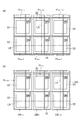
- FIG. 7A is a plan view of the light receiving unit 20 and shows an example of a boundary line (seam) LA for joint exposure.
- the lines passing through the center of the rectangular photodiode 22 are defined as the boundary lines LA and LB.
- the size of the photodiodes 22 in the carrier capture regions DA 1 to DA M , DB 1 to DB N + 1 is equal to that of the pixels P 1,1 to P M, N.
- the size of 22 is almost the same.
- FIG. 8A is a plan view of the light receiving unit 20 and shows another example of the boundary line LA for joint exposure.
- the column direction of the boundary line LA is, is closer to the left side (i.e. the side away from the carrier capturing regions DA 1 ⁇ DA M) with respect to the center of the rectangular photodiode 22,
- the boundary line LB in the row direction is closer to the upper side (that is, the side away from the carrier trapping regions DB 1 to DB N ) than the center of the rectangular photodiode 22.
- the boundary line LB in the row direction is closer to the upper side (that is, the side away from the carrier trapping regions DB 1 to DB N ) than the center of the rectangular photodiode 22.
- the size of the photodiodes 22 in the carrier capture regions DA 1 to DA M , DB 1 to DB N + 1 is set to the photodiodes of the pixels P 1,1 to P M, N.
- the size can be smaller than 22.
- the width of the carrier capturing regions DA 1 ⁇ DA M of photodiodes 22 in the row direction shorter than the width of the pixel P 1,1 ⁇ P M, N of the photodiode 22 in the direction . Further, it is possible to shorten the width of the carrier capture region DB 1 ⁇ DB N photodiode 22, the pixels P 1, 1 ⁇ P M in the direction, than the width of the N photodiodes 22 in the row direction. Therefore, the area required around the light receiving unit 20 can be narrowed.
- FIG. 9 is a plan view schematically showing an example in which two glass substrates 12 are arranged side by side. On these glass substrates 12, pixels P 1,1 to P M, N of the light receiving unit 20 and carrier capture regions DA 1 to DA M and DB 1 to DB N + 1 are formed. In order to further increase the area of the light receiving portion in the entire solid-state imaging device, it is effective to arrange a plurality of glass substrates 12 side by side in this manner.
- the pixel P 1,1 ⁇ P M in the two glass substrates 12 on, N if the arrangement of the carrier capture region DA 1 ⁇ DA M and DB 1 ⁇ DB N identical, and common parts manufacturing Cost can be kept low. However, in that case, it becomes the carrier capture region DA 1 ⁇ DA M between the two light receiving portion 20 is located, the region becomes a dead zone can not be obtained image (dead areas). In this case, the width of the carrier capture region DA 1 ⁇ DA M of photodiodes 22 in the row direction, the pixel P 1,1 ⁇ P M in the direction by less than the width of the N photodiodes 22, The insensitive area can be narrowed.
- a transistor in a normal pixel P m + 1, n , a transistor is formed on the side closer to P m + 1, n + 1 .
- the pixel P m + 1, n seams (boundaries LA) is present on the side close to the pixel P m + 1, n-1 . That is, with respect to the center of the pixel P m + 1, n , a transistor is present on one side of the pixel and a seam (boundary line LA) is present on the other side, and the distance between the seam and the transistor is increased in the row direction. In this way, since the seam and the transistor can be physically separated, manufacturing defects can be reduced.
- the solid-state imaging device is not limited to the above-described embodiment, and various other modifications are possible.
- the light receiving unit shown in the above embodiment may have a configuration in which amorphous silicon or polycrystalline silicon is formed on a glass substrate.
- the transistor 21 is preferably realized by a thin film transistor.
- the light receiving portion may be fabricated on a single crystal silicon substrate.
- the present invention is applied to a so-called passive pixel sensor (PPS) in which each pixel does not have an amplifier circuit and an integration circuit is provided for each readout wiring in each column.
- PPS passive pixel sensor
- APS active pixel sensor
- the solid-state imaging device includes a first photodiode and a first switch circuit having one end connected to the first photodiode, and M rows and N columns (M and N are integers of 2 or more).
- M and N are integers of 2 or more.
- Two-dimensionally arrayed light receiving units having M ⁇ N pixels, and N pixels arranged for each column and connected to the other end of the first switch circuit included in the corresponding column of pixels.
- the readout wiring, the N integration circuits that respectively output voltage values corresponding to the amount of electric charges input through the N readout wirings, and the light receiving portion are arranged side by side in the row direction.
- a shift register for controlling the open / close state of the switch circuit for each row M dummy photodiodes arranged for each row in a region between the shift register and the light receiving unit, and M dummy photodiodes respectively.
- M second connected at one end A switch circuit uses a configuration including a charge and discharge lines which are short-circuited to the reference potential line is connected to the other end of the M second switch circuit.
- the solid-state imaging device may be configured such that the width of the dummy photodiode in the row direction is shorter than the width of the first photodiode in the direction.
- the size of the dummy photodiode is not necessarily equal to that of the first photodiode. Therefore, by making the width of the dummy photodiode shorter than the width of the first photodiode in this way, the area around the light receiving unit is narrowed, and for example, when arranging a plurality of solid-state imaging devices side by side, the solid-state imaging device The insensitive area generated between them can be narrowed.
- the solid-state imaging device may have a configuration in which the shift register and the light receiving unit are formed on a common substrate. In such a case, unnecessary carriers generated in the shift register easily flow into the light receiving unit, but according to the solid-state imaging device, it is possible to effectively prevent the unnecessary carriers from flowing into the light receiving unit.
- the solid-state imaging device has M rows arranged for each row in order to electrically connect the control terminals of the first and second switch circuits for controlling the open / close state and the shift register to each other. It is good also as a structure further provided with the wiring for selection. As described above, the row selection wiring is provided in common to the first and second switch circuits, so that the magnitude of the crosstalk in the pixels adjacent to the dummy photodiodes can be reduced. Can be even closer.
- the present invention can be used as a solid-state imaging device capable of bringing the output characteristics and noise magnitude of pixels adjacent to a dummy photodiode closer to other pixels.
Landscapes
- Engineering & Computer Science (AREA)
- Multimedia (AREA)
- Signal Processing (AREA)
- Transforming Light Signals Into Electric Signals (AREA)
- Solid State Image Pick-Up Elements (AREA)
Abstract
Description
Claims (4)
- 第1のフォトダイオード、及び該第1のフォトダイオードに一端が接続された第1のスイッチ回路を各々含み、M行N列(M,Nは2以上の整数)に二次元配列されたM×N個の画素を有する受光部と、
各列毎に配設され、対応する列の前記画素に含まれる前記第1のスイッチ回路の他端に接続されたN本の読出用配線と、
前記N本の読出用配線に接続された読出回路部と、
前記受光部に対して行方向に並んで配置され、前記第1のスイッチ回路の開閉状態を各行毎に制御するシフトレジスタと、
前記シフトレジスタと前記受光部との間の領域において各行毎に配置されたM個のダミーフォトダイオードと、
前記M個のダミーフォトダイオードにそれぞれの一端が接続されたM個の第2のスイッチ回路と、
前記M個の第2のスイッチ回路の他端に接続されるとともに基準電位線に短絡された電荷排出用配線と
を備えることを特徴とする、固体撮像装置。 - 行方向における前記ダミーフォトダイオードの幅が、該方向における前記第1のフォトダイオードの幅よりも短いことを特徴とする、請求項1に記載の固体撮像装置。
- 前記シフトレジスタと前記受光部とが共通の基板上に形成されていることを特徴とする、請求項1または2に記載の固体撮像装置。
- 開閉状態を制御するための前記第1及び第2のスイッチ回路の各制御端子と前記シフトレジスタとを互いに電気的に接続するために各行毎に配設されたM本の行選択用配線を更に備えることを特徴とする、請求項1~3のいずれか一項に記載の固体撮像装置。
Priority Applications (7)
| Application Number | Priority Date | Filing Date | Title |
|---|---|---|---|
| US14/897,144 US10090341B2 (en) | 2013-06-11 | 2014-05-29 | Solid-state imaging device |
| KR1020217008953A KR102398375B1 (ko) | 2013-06-11 | 2014-05-29 | 고체 촬상 장치 |
| EP14811345.9A EP3010227B1 (en) | 2013-06-11 | 2014-05-29 | Solid-state imaging device |
| KR1020157033521A KR102333891B1 (ko) | 2013-06-11 | 2014-05-29 | 고체 촬상 장치 |
| CN201480033464.0A CN105284104B (zh) | 2013-06-11 | 2014-05-29 | 固体摄像装置 |
| EP20170348.5A EP3709363A1 (en) | 2013-06-11 | 2014-05-29 | Solid-state imaging device |
| US16/055,927 US10685991B2 (en) | 2013-06-11 | 2018-08-06 | Solid-state imaging device |
Applications Claiming Priority (2)
| Application Number | Priority Date | Filing Date | Title |
|---|---|---|---|
| JP2013122910A JP5886793B2 (ja) | 2013-06-11 | 2013-06-11 | 固体撮像装置 |
| JP2013-122910 | 2013-06-11 |
Related Child Applications (2)
| Application Number | Title | Priority Date | Filing Date |
|---|---|---|---|
| US14/897,144 A-371-Of-International US10090341B2 (en) | 2013-06-11 | 2014-05-29 | Solid-state imaging device |
| US16/055,927 Continuation US10685991B2 (en) | 2013-06-11 | 2018-08-06 | Solid-state imaging device |
Publications (1)
| Publication Number | Publication Date |
|---|---|
| WO2014199838A1 true WO2014199838A1 (ja) | 2014-12-18 |
Family
ID=52022137
Family Applications (1)
| Application Number | Title | Priority Date | Filing Date |
|---|---|---|---|
| PCT/JP2014/064319 Ceased WO2014199838A1 (ja) | 2013-06-11 | 2014-05-29 | 固体撮像装置 |
Country Status (7)
| Country | Link |
|---|---|
| US (2) | US10090341B2 (ja) |
| EP (2) | EP3010227B1 (ja) |
| JP (1) | JP5886793B2 (ja) |
| KR (2) | KR102333891B1 (ja) |
| CN (1) | CN105284104B (ja) |
| TW (1) | TWI610572B (ja) |
| WO (1) | WO2014199838A1 (ja) |
Families Citing this family (9)
| Publication number | Priority date | Publication date | Assignee | Title |
|---|---|---|---|---|
| WO2017126242A1 (ja) * | 2016-01-18 | 2017-07-27 | 富士フイルム株式会社 | 撮像装置、及び、画像データ生成方法 |
| WO2018206606A1 (en) * | 2017-05-08 | 2018-11-15 | Vrije Universiteit Brussel | Detector for fast-gated detection of electromagnetic radiation |
| JP7167061B2 (ja) * | 2017-05-08 | 2022-11-08 | フリーイェ・ユニヴェルシテイト・ブリュッセル | 電磁放射線のファーストゲート式検出のための検出器 |
| CN109087925B (zh) * | 2018-08-09 | 2020-11-13 | 京东方科技集团股份有限公司 | 阵列基板、x射线平板探测器及x射线探测方法 |
| JP7446826B2 (ja) * | 2020-01-23 | 2024-03-11 | 株式会社ジャパンディスプレイ | 検出装置 |
| JP2022012182A (ja) * | 2020-07-01 | 2022-01-17 | キヤノン電子管デバイス株式会社 | 放射線検出器 |
| JP7361008B2 (ja) * | 2020-10-16 | 2023-10-13 | キヤノン電子管デバイス株式会社 | 放射線検出器 |
| CN113204506B (zh) * | 2021-04-09 | 2022-06-14 | 华中科技大学 | 一种基于时分复用的智能超表面控制方法、装置及系统 |
| US12225304B2 (en) * | 2022-04-27 | 2025-02-11 | Semiconductor Components Industries, Llc | Expanded image sensor pixel array |
Citations (4)
| Publication number | Priority date | Publication date | Assignee | Title |
|---|---|---|---|---|
| JP2007050053A (ja) | 2005-08-16 | 2007-03-01 | Canon Inc | 放射線撮像装置、その制御方法及び放射線撮像システム |
| US20080218608A1 (en) * | 2007-03-07 | 2008-09-11 | Altasens, Inc. | Apparatus and method for reducing edge effect in an image sensor |
| US20100193692A1 (en) * | 2007-09-25 | 2010-08-05 | Harumichi Mori | Solid state imaging device |
| US20110032391A1 (en) * | 2009-08-04 | 2011-02-10 | Himax Imaging, Inc. | Image Sensor with Peripheral Dummy Pixels |
Family Cites Families (23)
| Publication number | Priority date | Publication date | Assignee | Title |
|---|---|---|---|---|
| JP3146509B2 (ja) * | 1991-04-05 | 2001-03-19 | 富士ゼロックス株式会社 | 2次元密着型イメージセンサ |
| JP4386213B2 (ja) | 1998-09-24 | 2009-12-16 | キヤノン株式会社 | 光電変換装置及び画素パネル |
| JP2010246129A (ja) * | 1999-06-07 | 2010-10-28 | Toshiba Corp | 放射線検出器 |
| JP2001056382A (ja) | 1999-06-07 | 2001-02-27 | Toshiba Corp | 放射線検出器及び放射線診断装置 |
| JP2004037382A (ja) * | 2002-07-05 | 2004-02-05 | Toshiba Corp | 放射線検出器及び放射線診断装置 |
| US6928144B2 (en) | 2003-08-01 | 2005-08-09 | General Electric Company | Guard ring for direct photo-to-electron conversion detector array |
| JP3890333B2 (ja) * | 2004-02-06 | 2007-03-07 | キヤノン株式会社 | 固体撮像装置 |
| JP2006073621A (ja) | 2004-08-31 | 2006-03-16 | Canon Inc | 測距用固体撮像装置とこれを用いたオートフォーカスカメラ |
| KR100670538B1 (ko) * | 2004-12-30 | 2007-01-16 | 매그나칩 반도체 유한회사 | 광 특성을 향상시킬 수 있는 이미지센서 및 그 제조 방법 |
| JP4130211B2 (ja) | 2006-05-31 | 2008-08-06 | 三洋電機株式会社 | 撮像装置 |
| JP2008252691A (ja) * | 2007-03-30 | 2008-10-16 | Fujifilm Corp | 画像信号取得方法および装置 |
| JP5214904B2 (ja) * | 2007-04-12 | 2013-06-19 | ルネサスエレクトロニクス株式会社 | 固体撮像素子の製造方法 |
| JP4935486B2 (ja) * | 2007-04-23 | 2012-05-23 | ソニー株式会社 | 固体撮像装置、固体撮像装置の駆動方法、固体撮像装置の信号処理方法および撮像装置 |
| JP5406473B2 (ja) | 2007-07-19 | 2014-02-05 | キヤノン株式会社 | 放射線検出装置 |
| US8063350B2 (en) * | 2007-08-03 | 2011-11-22 | Cognex Corporation | Circuits and methods allowing for pixel array exposure pattern control |
| JP5188221B2 (ja) * | 2008-03-14 | 2013-04-24 | キヤノン株式会社 | 固体撮像装置 |
| JP5281943B2 (ja) * | 2009-04-01 | 2013-09-04 | 浜松ホトニクス株式会社 | 固体撮像装置 |
| JP5683850B2 (ja) * | 2010-01-28 | 2015-03-11 | 富士フイルム株式会社 | 放射線検出素子、及び放射線画像撮影装置 |
| TW201226864A (en) | 2010-12-29 | 2012-07-01 | Himax Imaging Inc | Digital image device with ambient light sensor |
| JP2012195734A (ja) * | 2011-03-16 | 2012-10-11 | Sony Corp | 固体撮像装置、撮像装置、電子機器、及び、固体撮像装置の駆動方法 |
| JP5749534B2 (ja) * | 2011-03-25 | 2015-07-15 | 浜松ホトニクス株式会社 | 赤外線イメージセンサ及び信号読み出し方法 |
| TWI596515B (zh) | 2011-10-14 | 2017-08-21 | 劉鴻達 | 交錯式驅動的觸控感應方法、觸控感應模組及顯示器 |
| JP5444444B2 (ja) * | 2012-12-03 | 2014-03-19 | 浜松ホトニクス株式会社 | 固体撮像装置 |
-
2013
- 2013-06-11 JP JP2013122910A patent/JP5886793B2/ja active Active
-
2014
- 2014-05-29 WO PCT/JP2014/064319 patent/WO2014199838A1/ja not_active Ceased
- 2014-05-29 CN CN201480033464.0A patent/CN105284104B/zh active Active
- 2014-05-29 US US14/897,144 patent/US10090341B2/en active Active
- 2014-05-29 KR KR1020157033521A patent/KR102333891B1/ko active Active
- 2014-05-29 KR KR1020217008953A patent/KR102398375B1/ko active Active
- 2014-05-29 EP EP14811345.9A patent/EP3010227B1/en active Active
- 2014-05-29 EP EP20170348.5A patent/EP3709363A1/en not_active Ceased
- 2014-06-09 TW TW103119946A patent/TWI610572B/zh active
-
2018
- 2018-08-06 US US16/055,927 patent/US10685991B2/en active Active
Patent Citations (4)
| Publication number | Priority date | Publication date | Assignee | Title |
|---|---|---|---|---|
| JP2007050053A (ja) | 2005-08-16 | 2007-03-01 | Canon Inc | 放射線撮像装置、その制御方法及び放射線撮像システム |
| US20080218608A1 (en) * | 2007-03-07 | 2008-09-11 | Altasens, Inc. | Apparatus and method for reducing edge effect in an image sensor |
| US20100193692A1 (en) * | 2007-09-25 | 2010-08-05 | Harumichi Mori | Solid state imaging device |
| US20110032391A1 (en) * | 2009-08-04 | 2011-02-10 | Himax Imaging, Inc. | Image Sensor with Peripheral Dummy Pixels |
Non-Patent Citations (1)
| Title |
|---|
| See also references of EP3010227A4 |
Also Published As
| Publication number | Publication date |
|---|---|
| TW201448600A (zh) | 2014-12-16 |
| KR102398375B1 (ko) | 2022-05-16 |
| EP3010227B1 (en) | 2020-06-24 |
| TWI610572B (zh) | 2018-01-01 |
| KR20210036423A (ko) | 2021-04-02 |
| US20180374882A1 (en) | 2018-12-27 |
| US10090341B2 (en) | 2018-10-02 |
| KR20160019059A (ko) | 2016-02-18 |
| EP3010227A4 (en) | 2017-02-15 |
| JP2014241490A (ja) | 2014-12-25 |
| US10685991B2 (en) | 2020-06-16 |
| KR102333891B1 (ko) | 2021-12-02 |
| EP3010227A1 (en) | 2016-04-20 |
| JP5886793B2 (ja) | 2016-03-16 |
| CN105284104A (zh) | 2016-01-27 |
| EP3709363A1 (en) | 2020-09-16 |
| US20160126269A1 (en) | 2016-05-05 |
| CN105284104B (zh) | 2019-03-15 |
Similar Documents
| Publication | Publication Date | Title |
|---|---|---|
| JP5886793B2 (ja) | 固体撮像装置 | |
| JP6188433B2 (ja) | 固体撮像装置 | |
| KR102158897B1 (ko) | 고체 촬상 장치 | |
| US20150155325A1 (en) | Semiconductor module, mos type solid-state image pickup device, camera and manufacturing method of camera | |
| JP5714982B2 (ja) | 固体撮像素子の制御方法 | |
| KR101575378B1 (ko) | 고체 촬상 장치 및 이를 포함하는 x선 ct 장치 | |
| CN107277396B (zh) | 摄像装置 | |
| JP2015185823A (ja) | 固体撮像素子、及び、撮像装置 | |
| JP2014120858A (ja) | 固体撮像装置 | |
| KR101916485B1 (ko) | 고체 촬상 장치 | |
| US10212368B2 (en) | Solid-state imaging device | |
| JP5749873B1 (ja) | 固体撮像素子の制御方法 | |
| WO2014178179A1 (ja) | 固体撮像素子および撮像装置 | |
| JP6185098B2 (ja) | 固体撮像装置 | |
| JP6255527B1 (ja) | 固体撮像装置 | |
| CN118922944A (zh) | 摄像装置及相机系统 |
Legal Events
| Date | Code | Title | Description |
|---|---|---|---|
| WWE | Wipo information: entry into national phase |
Ref document number: 201480033464.0 Country of ref document: CN |
|
| 121 | Ep: the epo has been informed by wipo that ep was designated in this application |
Ref document number: 14811345 Country of ref document: EP Kind code of ref document: A1 |
|
| ENP | Entry into the national phase |
Ref document number: 20157033521 Country of ref document: KR Kind code of ref document: A |
|
| WWE | Wipo information: entry into national phase |
Ref document number: 14897144 Country of ref document: US |
|
| WWE | Wipo information: entry into national phase |
Ref document number: 2014811345 Country of ref document: EP |
|
| NENP | Non-entry into the national phase |
Ref country code: DE |