WO2014199946A1 - モータ - Google Patents
モータ Download PDFInfo
- Publication number
- WO2014199946A1 WO2014199946A1 PCT/JP2014/065221 JP2014065221W WO2014199946A1 WO 2014199946 A1 WO2014199946 A1 WO 2014199946A1 JP 2014065221 W JP2014065221 W JP 2014065221W WO 2014199946 A1 WO2014199946 A1 WO 2014199946A1
- Authority
- WO
- WIPO (PCT)
- Prior art keywords
- pole
- salient
- poles
- salient pole
- motor
- Prior art date
- Legal status (The legal status is an assumption and is not a legal conclusion. Google has not performed a legal analysis and makes no representation as to the accuracy of the status listed.)
- Ceased
Links
Images


Classifications
-
- H—ELECTRICITY
- H02—GENERATION; CONVERSION OR DISTRIBUTION OF ELECTRIC POWER
- H02K—DYNAMO-ELECTRIC MACHINES
- H02K3/00—Details of windings
- H02K3/32—Windings characterised by the shape, form or construction of the insulation
- H02K3/325—Windings characterised by the shape, form or construction of the insulation for windings on salient poles, such as claw-shaped poles
-
- G—PHYSICS
- G04—HOROLOGY
- G04C—ELECTROMECHANICAL CLOCKS OR WATCHES
- G04C3/00—Electromechanical clocks or watches independent of other time-pieces and in which the movement is maintained by electric means
- G04C3/008—Mounting, assembling of components
-
- G—PHYSICS
- G04—HOROLOGY
- G04C—ELECTROMECHANICAL CLOCKS OR WATCHES
- G04C3/00—Electromechanical clocks or watches independent of other time-pieces and in which the movement is maintained by electric means
- G04C3/14—Electromechanical clocks or watches independent of other time-pieces and in which the movement is maintained by electric means incorporating a stepping motor
-
- H—ELECTRICITY
- H02—GENERATION; CONVERSION OR DISTRIBUTION OF ELECTRIC POWER
- H02K—DYNAMO-ELECTRIC MACHINES
- H02K1/00—Details of the magnetic circuit
- H02K1/06—Details of the magnetic circuit characterised by the shape, form or construction
- H02K1/12—Stationary parts of the magnetic circuit
- H02K1/14—Stator cores with salient poles
- H02K1/146—Stator cores with salient poles consisting of a generally annular yoke with salient poles
-
- H—ELECTRICITY
- H02—GENERATION; CONVERSION OR DISTRIBUTION OF ELECTRIC POWER
- H02K—DYNAMO-ELECTRIC MACHINES
- H02K21/00—Synchronous motors having permanent magnets; Synchronous generators having permanent magnets
- H02K21/12—Synchronous motors having permanent magnets; Synchronous generators having permanent magnets with stationary armatures and rotating magnets
- H02K21/14—Synchronous motors having permanent magnets; Synchronous generators having permanent magnets with stationary armatures and rotating magnets with magnets rotating within the armatures
- H02K21/16—Synchronous motors having permanent magnets; Synchronous generators having permanent magnets with stationary armatures and rotating magnets with magnets rotating within the armatures having annular armature cores with salient poles
-
- H—ELECTRICITY
- H02—GENERATION; CONVERSION OR DISTRIBUTION OF ELECTRIC POWER
- H02K—DYNAMO-ELECTRIC MACHINES
- H02K3/00—Details of windings
- H02K3/04—Windings characterised by the conductor shape, form or construction, e.g. with bar conductors
- H02K3/28—Layout of windings or of connections between windings
-
- H—ELECTRICITY
- H02—GENERATION; CONVERSION OR DISTRIBUTION OF ELECTRIC POWER
- H02K—DYNAMO-ELECTRIC MACHINES
- H02K37/00—Motors with rotor rotating step by step and without interrupter or commutator driven by the rotor, e.g. stepping motors
- H02K37/10—Motors with rotor rotating step by step and without interrupter or commutator driven by the rotor, e.g. stepping motors of permanent magnet type
- H02K37/12—Motors with rotor rotating step by step and without interrupter or commutator driven by the rotor, e.g. stepping motors of permanent magnet type with stationary armatures and rotating magnets
- H02K37/14—Motors with rotor rotating step by step and without interrupter or commutator driven by the rotor, e.g. stepping motors of permanent magnet type with stationary armatures and rotating magnets with magnets rotating within the armatures
-
- H—ELECTRICITY
- H02—GENERATION; CONVERSION OR DISTRIBUTION OF ELECTRIC POWER
- H02K—DYNAMO-ELECTRIC MACHINES
- H02K1/00—Details of the magnetic circuit
- H02K1/06—Details of the magnetic circuit characterised by the shape, form or construction
- H02K1/12—Stationary parts of the magnetic circuit
- H02K1/14—Stator cores with salient poles
-
- H—ELECTRICITY
- H02—GENERATION; CONVERSION OR DISTRIBUTION OF ELECTRIC POWER
- H02K—DYNAMO-ELECTRIC MACHINES
- H02K7/00—Arrangements for handling mechanical energy structurally associated with dynamo-electric machines, e.g. structural association with mechanical driving motors or auxiliary dynamo-electric machines
- H02K7/10—Structural association with clutches, brakes, gears, pulleys or mechanical starters
- H02K7/116—Structural association with clutches, brakes, gears, pulleys or mechanical starters with gears
Definitions
- the present invention relates to a motor in which a coil is wound around two salient poles among a plurality of salient poles of a stator core provided along a circumferential surface of a magnet.
- Patent Document 1 a structure in which a pointer is attached to an output shaft of a motor may be employed.
- a motor used in such a display device a configuration in which a plurality of salient poles of a stator core are arranged along a peripheral surface of a magnet, and a coil is wound around two salient poles among the plurality of salient poles ( Patent Document 2).
- Patent Document 2 a configuration in which a plurality of salient poles of a stator core are arranged along a peripheral surface of a magnet, and a coil is wound around two salient poles among the plurality of salient poles.
- Patent Document 2 three or five pairs of S poles and N poles are arranged on the outer peripheral surface of the magnet, and the number of salient poles is eight, and two salient poles whose angular positions are shifted by 90 °. The coil is wound around.
- JP 2013-57567 A Japanese Patent No. 4125371
- an object of the present invention is to provide a motor capable of reducing the volume generated when the rotor is accelerated or decelerated.
- a motor according to the present invention includes a rotor including a magnet having S poles and N poles alternately provided at equal angular intervals in the circumferential direction, and a gap in the circumferential surface.
- a stator core having a plurality of salient poles facing each other in the circumferential direction, a first coil wound around the first salient pole among the plurality of salient poles, and the first of the plurality of salient poles.
- the magnet has four pairs of S poles and N poles at equal angular intervals, and the stator core has six salient poles.
- the first coil wound around the first coil is wound.
- One salient pole and the second salient pole wound with the second coil are such that when one salient pole faces between the S pole and the N pole, the other salient pole is the center of the S pole or the N pole. It is arranged so as to face the center.
- the first salient pole and the second salient pole may adopt a configuration in which the angular position is shifted by 112.5 ° in the circumferential direction.
- the first salient pole around which the first coil is wound and the second salient pole around which the second coil is wound are such that one salient pole is an S pole.
- the other salient pole faces the center of the S pole or the center of the N pole.
- the stator core is preferably formed by laminating a plurality of magnetic plates. According to this configuration, even when there are many salient poles, the magnetic plate is thin when the magnetic plate is punched into the shape of the stator core, so that the magnetic plate can be punched efficiently and accurately.
- the first salient pole and the second salient pole are longer in the radial direction than the other salient poles, and the first coil is wound around the first salient pole. It is preferable that the radial dimension of the portion and the radial dimension of the winding portion of the second coil with respect to the second salient pole are longer than the radial dimension of the other salient pole. According to such a configuration, a sufficient number of coil turns can be ensured.
- a gear reduction mechanism for reducing and transmitting the rotation of the rotor is provided. According to such a configuration, there is no need to provide a gear reduction mechanism outside the motor.
- the magnet has four pairs of S poles and N poles at equal angular intervals, and the stator core has six salient poles.
- the first coil wound around the first coil is wound.
- One salient pole and the second salient pole wound with the second coil are such that when one salient pole faces between the S pole and the N pole, the other salient pole is the center of the S pole or the N pole. It is arranged so as to face the center.
- FIG. 1 is an explanatory view of a motor to which the present invention is applied.
- FIGS. 1A, 1B, and 1C are a plan view of a motor, a side view of the motor, and a plan view of a stator and the like.
- the motor 1 of this embodiment includes a case 3, a rotor 5 rotatably supported by the case 3, and a stator 7 disposed around the rotor 5.
- a support shaft 51 is fixed to the case 3, and the rotor 5 is rotatably supported by the support shaft 51. Therefore, the rotor 5 is rotatably supported by the case 3 via the support shaft 51.
- the motor 1 has a reduction gear mechanism 9 that reduces the rotation of the rotor 5 and transmits it to the output shaft 90.
- the reduction gear mechanism 9 is also supported by the case 3 like the rotor 5 and the stator 7. ing.
- the rotor 5 includes a pinion 53 that is rotatably supported by the support shaft 51 and a cylindrical magnet 6 that is integrated with the pinion 53.
- the magnet 6 and the pinion 53 are integrated by insert molding. For this reason, the magnet 6 and the pinion 53 are coupled by the resin disc portion 50.
- the magnet 6 is a ferrite type.
- the stator 7 includes a stator core 8 provided with a plurality of salient poles 80 facing the outer circumferential surface 60 (peripheral surface) of the magnet 6 with a gap, and an insulator 71 on the first salient pole 81 among the plurality of salient poles 80. And a second coil 77 wound around the second salient pole 82 via the insulator 72 among the plurality of salient poles 80.
- Two terminals 710 for feeding power to the first coil 76 are held at the end of the insulator 71, and two terminals 720 for feeding power to the second coil 77 are held at the end of the insulator 72.
- the terminals 710 and 720 are wound around the winding start and winding end of the first coil 76 and the winding start and winding end of the second coil 77.
- the reduction gear mechanism 9 includes a first gear 91 having a large-diameter gear 91a that meshes with the pinion 53, and a large-diameter second gear 92 that meshes with the small-diameter gear 91b of the first gear 91.
- An output shaft 90 is fixed to the two gears 92.
- the drive pulse of each phase is supplied to the first coil 76 and the second coil 77 via the terminals 710 and 720, whereby the rotor 5 is rotated and the rotation of the rotor 5 is decelerated. This is transmitted to the output shaft 90 via the gear mechanism 9.
- a pointer-type display device is configured using the motor 1, a pointer (not shown) is fixed to the output shaft 90. In such a display device, the angular position of the pointer is switched by the drive pulse supplied to the first coil 76 and the second coil 77 via the terminals 710 and 720.
- the magnet 6 is provided with S poles and N poles on the outer circumferential surface 60 alternately at equal angular intervals in the circumferential direction.
- the magnet 6 has four pairs of S poles and N poles. For this reason, in the magnet 6, since the S pole and the N pole are formed at equal angular intervals, a total of 8 poles, the angular positions of the S pole and the N pole adjacent in the circumferential direction are shifted by 45 °. .
- the stator core 8 has an opening 84 where the magnet 6 is disposed, and a plurality of salient poles 80 projecting toward the outer peripheral surface 60 of the magnet 6 are provided in the circumferential direction on the inner peripheral edge of the opening 84. Has been placed.
- the radially inner end of the salient pole 80 faces the outer peripheral surface 60 of the magnet 6 via a gap, and the gap dimension between the radially inner end of the salient pole 80 and the outer peripheral surface 60 of the magnet 6 is as follows. The same for all of the plurality of salient poles 80. In this embodiment, the number of salient poles 80 is six.
- the salient poles 80 are arranged at unequal intervals, but the first salient pole 81 around which the first coil 76 is wound and the second salient pole 82 around which the second coil 77 is wound are:
- the circumferential center of the other salient pole is the circumferential direction of the S pole.
- the center of the N pole in the circumferential direction More specifically, among the plurality of salient poles 80, two salient poles 80 whose angular positions are shifted by 112.5 ° in the circumferential direction are used as the first salient pole 81 and the second salient pole 82.
- one of the two salient poles 80 whose angular positions are shifted by 112.5 ° has the tubular insulator 71 around which the first coil 76 is wound fitted outside.
- the other is a first salient pole 81
- the other is a second salient pole 82 in which a cylindrical insulator 72 around which a second coil 77 is wound is fitted.
- the angular position of the first salient pole 81 and the second salient pole 82 is shifted by 112.5 ° means that the center in the circumferential direction of the first salient pole 81 and the circumferential direction of the second salient pole 82. It means that the center is displaced by 112.5 ° in the angular position.
- One salient pole 80 around which no coil is wound exists between the first salient pole 81 and the second salient pole 82. Accordingly, the intervals between the salient poles 80 adjacent in the circumferential direction are 56.25 °, 56.25 °, 56.25 clockwise from the first salient pole 81 toward FIG. °, 67.5 °, 67.5 °, 56.25 °.
- the first salient pole 81 and the second salient pole 82 are longer in the radial direction than the other salient poles 80. For this reason, the radial dimension of the winding portion of the first coil 76 relative to the first salient pole 81 and the radial dimension of the winding portion of the second coil 77 relative to the second salient pole 82 are the other salient poles 80. Longer than the radial dimension.
- the first salient pole 81 and the second salient pole 82 have the same radial dimension, and the radial dimension of the winding portion of the first coil 76 relative to the first salient pole 81 and the second salient pole 82 second dimension. The dimension in the radial direction of the winding portion of the coil 77 is equal.
- salient poles 80 other than the first salient pole 81 and the second salient pole 82 project in the radial direction, that is, from the connecting portion 85 described later toward the outer peripheral surface 60 of the magnet 6. Since all the salient poles 80 have the same length, the radially outer ends of the salient poles 80 other than the first salient pole 81 and the second salient pole 82 are located at the same distance from the magnet 6.
- first salient pole 81 and the second salient pole 82 have a longer radial dimension than the other salient poles 80, the radially outer end of the first salient pole 81 and the second salient pole The end portion on the radially outer side of 82 is located farther from the magnet 6 on the radially outer side than the end portion on the radially outer side of the other salient pole 80.
- the stator core 8 has a frame-like connecting portion 85 that connects the radially outer ends of all the salient poles 80 including the first salient poles 81 and the second salient poles 82.
- the width dimension of 85 is substantially the same over the entire circumference.
- the connecting portion 85 is an arc portion 86 concentric with the magnet 6 except for the angular range in which the first salient pole 81 and the second salient pole 82 are formed.
- the angle range in which the first salient pole 81 is formed in the connecting portion 85 is a rectangular portion 87 projecting radially outward in a rectangular frame shape, and the second salient pole 82 is formed.
- the angle range is a rectangular portion 88 that protrudes radially outward in a rectangular frame shape. Therefore, the rectangular portions 87 and 88 are recessed inward in the radial direction, but the portion 89 between the rectangular portions 87 and 88 is also formed in an arc shape.
- the width dimension of the arc part 86 and the width dimension of the rectangular parts 87 and 88 are the same, but the width dimension of the part 89 between the rectangular parts 87 and 88 is the width dimension of the arc part 86 or the like. It is wider than the width dimension of the rectangular portions 87 and 88.
- the stator core 8 has a plate shape, and is configured by stacking a plurality of magnetic plates punched into the above shape.
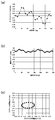
- FIG. 2 is a graph showing the results of the simulation of the characteristics of the motor 1 to which the present invention is applied.
- FIGS. 2 (a), 2 (b), and 2 (c) show the electrical angle of the motor 1 and the detent torque.
- 4 is a graph showing a relationship, a graph showing a relationship between an electrical angle of the motor 1 and an excitation torque, and a graph showing a Lissajous figure showing an electromagnetic force applied to the rotor 5 in the radial direction.
- FIG. 1 is a graph showing the results of the simulation of the characteristics of the motor 1 to which the present invention is applied.
- FIGS. 2 (a), 2 (b), and 2 (c) show the electrical angle of the motor 1 and the detent torque.
- 4 is a graph showing a relationship, a graph showing a relationship between an electrical angle of the motor 1 and an excitation torque, and a graph showing a Lissajous figure showing an electromagnetic force applied to the rotor 5 in the radial direction.
- one direction orthogonal to the rotation center axis of the rotor 5 is defined as an X-axis direction, and a force applied to the rotor 5 in the X-axis direction is defined as a horizontal axis.
- the direction perpendicular to the rotation center axis of the rotor 5 and the X-axis direction is the Y-axis direction
- the force applied to the rotor 5 in the Y-axis direction is the vertical axis.
- the stator core 8 is configured by punching a non-oriented electrical steel sheet having a thickness of 0.5 mm into the above shape and stacking three sheets.
- the magnet 6 has an inner diameter of 6 mm, an outer diameter of 8 mm, and an axial dimension of 3 mm.
- the first coil 76 and the second coil 77 are each formed by winding a coil wire having a diameter of 0.055 mm 2200 times, and the resistance value for one phase is 220 ⁇ .
- the driving voltage is 5V.
- FIG. 3 is an explanatory diagram of a motor 1 according to a comparative example with respect to the present invention, and the characteristics of the motor 1 were also obtained by simulation.
- the motor according to the first comparative example shown in FIG. 3A three pairs of S poles and N poles are formed on the magnet 6, and eight salient poles 80 are formed at equiangular intervals on the stator core 8. Further, the angular position of the first salient pole 81 around which the first coil 76 is wound and the second salient pole 82 around which the second coil 77 is wound are shifted by 90 °.
- the motor according to the second comparative example shown in FIG. 3B five pairs of S poles and N poles are formed on the magnet 6, and eight salient poles 80 are formed on the stator core 8. Further, the angular position of the first salient pole 81 around which the first coil 76 is wound and the second salient pole 82 around which the second coil 77 is wound are shifted by 90 °.
- the salient poles 80 are formed at unequal intervals, but the circumferential center of one of the first salient pole 81 and the second salient pole 82 is the boundary portion between the S pole and the N pole. Since the other salient pole faces the circumferential center of the S pole or the circumferential center of the N pole, there is no problem in generating the excitation torque.
- FIG. 4 is a graph showing results obtained by simulation of the characteristics of the motor according to the first comparative example of the present invention shown in FIG. 3 (a).
- FIGS. 4 (a), (b), and (c) It is a graph which shows the relationship between the electrical angle of a motor, and a detent torque, the graph which shows the relationship between the electrical angle of a motor, and a driving torque, and the graph which shows the Lissajous figure which shows the electromagnetic force added to the rotor 5 in a radial direction.
- FIG. 5 is a graph showing the results of the simulation of the characteristics of the motor according to the second comparative example of the present invention shown in FIG. 3 (b).
- FIG. 4 (a) and 5 (a) are data corresponding to FIG. 2 (a), and FIG. 4 (b) and FIG. 5 (b) are data corresponding to FIG. 2 (b).
- FIG. 4C and FIG. 5C are data corresponding to FIG. 2C.
- the motor according to the first comparative example shown in FIG. 3A and the motor according to the second comparative example shown in FIG. 3B are the motor 1 to which the present invention is applied, the size of the magnet 6 and the stator core.
- the basic configuration such as the size of 8 is the same, and only the number of poles of the magnet 6 and the number of salient poles 80 are different.
- the first comparative example is shown in the motor 1 to which the present invention is applied.
- the amount of change in the detent torque is smaller than that of the motor according to the second comparative example. Therefore, since the external force applied to the rotor 5 is small, it can be said that there is little vibration.
- the motor 1 to which the present invention is applied is compared with the motor according to the first comparative example.
- the excitation torque is small, the excitation torque necessary for the rotation of the rotor 5 can still be sufficiently obtained.
- the change in excitation torque is slightly smaller than that of the motor according to the first comparative example.
- the level of the excitation torque is the same.
- the motor 1 to which the present invention is applied has a slightly larger change in excitation torque than the motor according to the first comparative example, but the difference is small and can be said to be equivalent.
- the motor 1 to which the present invention is applied has a radial direction as compared with the motor according to the first comparative example.
- the force applied to the rotor 5 is small.
- the external force applied to the rotor 5 in the radial direction is small as compared with the motor according to the first comparative example, so that the vibration is small.
- the motor 1 to which the present invention is applied has a rotor in the radial direction as compared with the motor according to the first comparative example.
- the force applied to 5 is slightly larger.
- the magnet 6 has four pairs of S poles and N poles at equal angular intervals, and the stator core 8 has six salient poles 80 formed.
- the stator core 8 has six salient poles 80 formed.
- the first coil 76 of the plurality of salient poles 80 is wound.
- the magnet 6 A change in detent torque is smaller in the stator core 8 than in the motors according to Comparative Examples 1 and 2 in which three or five pairs of S poles and N poles are formed, and eight salient poles 80 are formed. For this reason, in the motor 1 of this embodiment, since the vibration of the rotor 5 is small, the volume generated when the rotor 5 is accelerated or decelerated can be reduced, and the noise can be reduced.
- the stator core 8 is formed by laminating a plurality of magnetic plates. For this reason, even when there are many salient poles 80 as in this embodiment, the magnetic plate is thin when the magnetic plate is punched into the shape of the stator core 8, so that the magnetic plate can be punched accurately.
- the first salient pole 81 and the second salient pole 82 have a longer radial dimension than the other salient poles 80, and the winding portion of the first coil 76 with respect to the first salient pole 81.
- the radial dimension of the winding portion of the second coil 77 with respect to the second salient pole 82 are larger than the radial dimensions of the other salient poles 80. Therefore, the excitation torque necessary for the rotation of the motor 1 can be obtained with certainty.
- the motor 1 is provided with the gear reduction mechanism 9 that reduces and transmits the rotation of the rotor 5, it is not necessary to provide the gear reduction mechanism 9 outside the motor 1. Therefore, only by attaching a pointer to the output shaft 90 in the motor 1 of the present embodiment, the main part of the display device can be configured, and the display device can be reduced in size.
- the rotor 5 is positioned inside the stator 7.
- the present invention may be applied to a motor in which the rotor 5 is positioned outside the stator 7.
- the salient pole 80 is configured to protrude radially outward from the stator core 8 and face the inner peripheral surface (peripheral surface) of the magnet 6.
Landscapes
- Engineering & Computer Science (AREA)
- Power Engineering (AREA)
- Physics & Mathematics (AREA)
- General Physics & Mathematics (AREA)
- Iron Core Of Rotating Electric Machines (AREA)
- Permanent Magnet Type Synchronous Machine (AREA)
Abstract
モータ1において、マグネット6はS極とN極とが4対等角度間隔に形成され、ステータコア8では突極80が6個形成されている。複数の突極80のうち、第1コイル76が巻回された第1突極81、および第2コイル77が巻回された第2突極82は、角度位置が112.5°ずれており、第1突極81および第2突極82は、一方の突極がS極とN極との間に対向するとき、他方の突極がS極の中心またはN極の中心と対向する。複数の突極80のうち、第1突極81および第2突極82は、他の突極80より径方向の寸法が長く、第1突極81に対する第1コイル76の巻回部分の径方向の寸法、および第2突極82に対する第2コイル77の巻回部分の径方向の寸法が、他の突極80の径方向の寸法より長い構成とすることにより、ロータの加速時や減速時に発生する音量を低減する。
Description
本発明は、マグネットの周面に沿って設けられたステータコアの複数の突極のうち、2つの突極にコイルが巻回されたモータに関するものである。
自動車用メータ装置や時計等の表示装置においては、モータの出力軸に指針を取り付けた構造が採用されることがある(特許文献1参照)。かかる表示装置に用いられるモータとして、マグネットの周面に沿ってステータコアの複数の突極を配置し、複数の突極のうち、2つの突極にコイルを巻回した構成が提案されている(特許文献2参照)。特許文献2に記載のモータでは、マグネットの外周面にS極とN極とを3対または5対配置するとともに、突極の数を8個とし、角度位置が90°ずれた2つの突極にコイルが巻回されている。
特許文献1に記載の表示装置等で用いるモータに関しては、十分な励磁トルクが得られることに加えて、ロータの加速時や減速時に発生する音量を低減することが求められているが、かかる要求に対しては、特許文献2に記載のモータでは十分に対応することができない。
以上の問題点に鑑みて、本発明の課題は、ロータの加速時や減速時に発生する音量を低減することのできるモータを提供することにある。
上記課題を解決するために、本発明に係るモータは、周面にS極とN極とが周方向で交互に等角度間隔に設けられたマグネットを備えたロータと、前記周面に隙間を隔てて対向する複数の突極が周方向に配置されたステータコア、前記複数の突極のうち、第1突極に巻回された第1コイル、および前記複数の突極のうち、前記第1突極に周方向で離間する第2突極に巻回された第2コイルを備えたステータと、を有し、前記マグネットでは、前記S極と前記N極とが4対形成され、前記ステータコアでは、前記突極が6個形成され、前記第1突極および前記第2突極は、一方の突極が前記S極と前記N極との間に対向するとき、他方の突極が前記S極の中心または前記N極の中心と対向するように配置されていることを特徴とする。
本発明に係るモータにおいて、マグネットはS極とN極とが等角度間隔に4対形成され、ステータコアでは、突極が6個形成されている。かかる構成の場合、突極を等角度間隔に配置すると、ロータの回転に十分な励磁トルクを得ることができないが、本発明では、複数の突極のうち、第1コイルが巻回された第1突極、および第2コイルが巻回された第2突極は、一方の突極がS極とN極との間に対向するとき、他方の突極がS極の中心またはN極の中心と対向するように配置されている。このため、ロータの回転に十分な励磁トルクを得ることができる。また、かかる構成のモータについて、電気角に対するディテントトルクの変化を検証したところ、マグネットにおいてS極とN極とが3対あるいは5対形成され、ステータコアでは、突極が8個形成されているモータより、ディテントトルクの変化が小さい。このため、ロータの振動が少ないので、ロータの加速時や減速時に発生する音量を低減することができ、低騒音化を図ることができる。
本発明において、前記第1突極と前記第2突極とは、周方向で角度位置が112.5°ずれている構成を採用することができる。かかる構成によれば、6個の突極のうち、第1コイルが巻回された第1突極、および第2コイルが巻回された第2突極は、一方の突極がS極とN極との間に対向するとき、他方の突極がS極の中心またはN極の中心と対向する。
本発明において、前記ステータコアは、複数枚の磁性板を積層してなることが好ましい。かかる構成によれば、突極が多い場合でも、磁性板をステータコアの形状に打ち抜く際に磁性板が薄いので、磁性板を効率よく、かつ精度よく打ち抜くことができる。
本発明において、前記複数の突極のうち、前記第1突極および前記第2突極は、他の突極より径方向の寸法が長く、前記第1突極に対する前記第1コイルの巻回部分の径方向の寸法、および前記第2突極に対する前記第2コイルの巻回部分の径方向の寸法が、前記他の突極の径方向の寸法より長いことが好ましい。かかる構成によれば、コイルの巻回数を十分に確保することができる。
本発明においては、前記ロータの回転を減速して伝達する歯車減速機構が設けられていることが好ましい。かかる構成によれば、モータの外部に歯車減速機構を設ける必要がない。
本発明に係るモータにおいて、マグネットはS極とN極とが等角度間隔に4対形成され、ステータコアでは、突極が6個形成されている。かかる構成の場合、突極を等角度間隔に配置すると、ロータの回転に十分な励磁トルクを得ることができないが、本発明では、複数の突極のうち、第1コイルが巻回された第1突極、および第2コイルが巻回された第2突極は、一方の突極がS極とN極との間に対向するとき、他方の突極がS極の中心またはN極の中心と対向するように配置されている。このため、ロータの回転に十分な励磁トルクを得ることができる。また、かかる構成のモータについて、電気角に対するディテントトルクの変化を検証したところ、マグネットにおいてS極とN極とが3対あるいは5対形成され、ステータコアでは、突極が8個形成されているモータより、ディテントトルクの変化が小さい。このため、ロータの振動が少ないので、ロータの加速時や減速時に発生する音量を低減することができ、低騒音化を図ることができる。
以下に、図面を参照して、本発明を適用したモータを説明する。
(モータの説明)
図1は、本発明を適用したモータの説明図であり、図1(a)、(b)、(c)は、モータの平面図、モータの側面図、およびステータ等の平面図である。
図1は、本発明を適用したモータの説明図であり、図1(a)、(b)、(c)は、モータの平面図、モータの側面図、およびステータ等の平面図である。
図1(a)、(b)に示すように、本形態のモータ1は、ケース3と、ケース3に回転可能に支持されたロータ5と、ロータ5の周りに配置されたステータ7とを有している。本形態において、ケース3には支軸51が固定されており、ロータ5は、支軸51に回転可能に支持されている。従って、ロータ5は、支軸51を介してケース3に回転可能に支持されている。また、モータ1は、ロータ5の回転を減速して出力軸90に伝達する減速歯車機構9を有しており、かかる減速歯車機構9も、ロータ5およびステータ7と同様、ケース3に支持されている。
ロータ5は、支軸51に回転可能に支持されたピニオン53と、ピニオン53と一体化された円筒状のマグネット6とを有している。本形態において、マグネット6とピニオン53とはインサート成形により一体化されている。このため、マグネット6とピニオン53とは、樹脂製の円板部50によって結合されている。本形態において、マグネット6はフェライト系である。
ステータ7は、マグネット6の外周面60(周面)に隙間を隔てて対向する複数の突極80を備えたステータコア8と、複数の突極80のうち、第1突極81にインシュレータ71を介して巻回された第1コイル76と、複数の突極80のうち、第2突極82にインシュレータ72を介して巻回された第2コイル77とを有している。インシュレータ71の端部には第1コイル76に対する2本の給電用の端子710が保持され、インシュレータ72の端部には第2コイル77に対する2本の給電用の端子720が保持されている。端子710、720には、第1コイル76の巻き始めと巻き終わりの端部、および第2コイル77の巻き始めと巻き終わりの端部が絡げられている。
減速歯車機構9は、ピニオン53に噛合する大径歯車91aを備えた第1歯車91と、第1歯車91の小径歯車91bに噛合する大径の第2歯車92とを有しており、第2歯車92に出力軸90が固定されている。
このように構成したモータ1では、端子710、720を介して第1コイル76および第2コイル77に各相の駆動パルスを供給することにより、ロータ5を回転させ、ロータ5の回転を、減速歯車機構9を介して出力軸90に伝達する。また、モータ1を用いて指針式の表示装置を構成する場合、出力軸90に指針(図示せず)が固定される。かかる表示装置では、端子710、720を介して第1コイル76および第2コイル77に供給された駆動パルスにより、指針の角度位置が切り換わる。その際、端子710、720に正回転用の駆動パルスを供給して指針を時計周りに目標位置まで回転させた後、端子710、720に停止用の駆動パルスを供給すれば、指針を目標位置で停止させることができる。また、この状態で、端子710、720に逆回転用の駆動パルスを供給すれば、指針を反時計周りに別の目標位置まで回転させることができる。
(マグネット6およびステータコア8の構成)
図1(c)に示すように、本形態のモータ1において、マグネット6は、外周面60にS極とN極とが周方向で交互に等角度間隔に設けられている。本形態において、マグネット6では、S極とN極とが4対形成されている。このため、マグネット6では、S極とN極とが計8極、等角度間隔で形成されていることから、周方向で隣り合うS極とN極とは、角度位置が45°ずれている。
図1(c)に示すように、本形態のモータ1において、マグネット6は、外周面60にS極とN極とが周方向で交互に等角度間隔に設けられている。本形態において、マグネット6では、S極とN極とが4対形成されている。このため、マグネット6では、S極とN極とが計8極、等角度間隔で形成されていることから、周方向で隣り合うS極とN極とは、角度位置が45°ずれている。
ステータコア8は、マグネット6が配置される部分が開口部84になっており、かかる開口部84の内周縁には、マグネット6の外周面60に向けて突出する複数の突極80が周方向に配置されている。突極80の径方向内側の端部は、マグネット6の外周面60に隙間を介して対向しており、突極80の径方向内側の端部とマグネット6の外周面60との隙間寸法は、複数の突極80のいずれにおいても等しい。本形態において、突極80の数は6個である。
ここで、突極80は、不等間隔に配置されているが、第1コイル76が巻回された第1突極81、および第2コイル77が巻回された第2突極82は、一方の突極の周方向の中心がS極とN極との間、すなわち、S極とN極との境界部分に対向するとき、他方の突極の周方向の中心がS極の周方向の中心またはN極の周方向の中心と対向するように配置されている。より具体的には、複数の突極80のうち、周方向で角度位置が112.5°ずれた2つの突極80が第1突極81および第2突極82として利用される。すなわち、複数の突極80のうち、角度位置が112.5°ずれた2つの突極80のうちの一方は、第1コイル76が巻回された筒状のインシュレータ71が外側に嵌められた第1突極81とされ、他方は、第2コイル77が巻回された筒状のインシュレータ72が外側に嵌められた第2突極82とされる。ここで、第1突極81と第2突極82とは、角度位置が112.5°ずれているとは、第1突極81の周方向の中心と第2突極82の周方向の中心とが、角度位置で112.5°ずれていることを意味する。なお、第1突極81と第2突極82との間には、コイルが巻回されていない突極80が1つ存在する。従って、周方向で隣り合う突極80の各間隔は、第1突極81を起点にすると、図1(c)に向かって時計周りに、56.25°、56.25°、56.25°、67.5°、67.5°、56.25°である。
本形態では、複数の突極80のうち、第1突極81および第2突極82は、他の突極80より径方向の寸法が長い。このため、第1突極81に対する第1コイル76の巻回部分の径方向の寸法、および第2突極82に対する第2コイル77の巻回部分の径方向の寸法が、他の突極80の径方向の寸法より長い。なお、第1突極81および第2突極82は、径方向の寸法が等しく、第1突極81に対する第1コイル76の巻回部分の径方向の寸法と第2突極82に対する第2コイル77の巻回部分の径方向の寸法とは等しい。
複数の突極80のうち、第1突極81および第2突極82以外の突極80は、径方向の寸法、すなわち、後述する連結部85からマグネット6の外周面60に向けて突出する突極80の長さ寸法が全て同一であるため、第1突極81および第2突極82以外の突極80の径方向外側の端部は、マグネット6から同一の距離の位置にある。これに対して、第1突極81および第2突極82は、他の突極80より径方向の寸法が長いので、第1突極81の径方向外側の端部、および第2突極82の径方向外側の端部は、他の突極80の径方向外側の端部よりも、マグネット6から径方向外側に離間した位置にある。
ここで、ステータコア8は、第1突極81および第2突極82を含む全ての突極80の径方向外側の端部を連結する枠状の連結部85を有しており、かかる連結部85の幅寸法は全周にわたって略同一である。このため、連結部85は、第1突極81および第2突極82が形成されている角度範囲以外は、マグネット6と同心状の円弧部86になっている。これに対して、連結部85は、第1突極81が形成されている角度範囲は、径方向外側に矩形枠状に突出した矩形部87になっており、第2突極82が形成されている角度範囲は、径方向外側に矩形枠状に突出した矩形部88になっている。従って、矩形部87、88の間は、径方向内側に凹んだ形状になっているが、矩形部87、88の間の部分89も円弧状に形成されている。なお、連結部85では、円弧部86の幅寸法と矩形部87,88の幅寸法は同一であるが、矩形部87、88の間の部分89の幅寸法は、円弧部86の幅寸法や矩形部87,88の幅寸法より広くなっている。
本形態において、ステータコア8は板状であり、上記の形状に打ち抜いた磁性板を複数枚、積層することにより、構成されている。
(モータ1の評価結果)
図2は、本発明を適用したモータ1の特性をシミュレーションにより求めた結果を示すグラフであり、図2(a)、(b)、(c)は、モータ1の電気角とディテントトルクとの関係を示すグラフ、モータ1の電気角と励磁トルクとの関係を示すグラフ、およびラジアル方向でロータ5に加わる電磁力を示すリサージュ図形を示すグラフである。なお、図2(c)では、ロータ5の回転中心軸線に直交する一方方向をX軸方向とし、かかるX軸方向でロータ5に加わる力を横軸としてある。また、図2(c)では、ロータ5の回転中心軸線およびX軸方向に直交する方向をY軸方向とし、かかるY軸方向でロータ5に加わる力を縦軸としてある。また、評価に用いたモータ1において、ステータコア8は、厚さが0.5mmの無方向性電磁鋼板を上記の形状に打ち抜いて3枚、積層することにより、構成されている。マグネット6は、内径が6mm、外径が8mm、軸線方向の寸法が3mmである。第1コイル76および第2コイル77は各々、径が0.055mmのコイル線を2200回、巻回してなり、その1相分の抵抗値は220Ωである。駆動電圧は5Vである。
図2は、本発明を適用したモータ1の特性をシミュレーションにより求めた結果を示すグラフであり、図2(a)、(b)、(c)は、モータ1の電気角とディテントトルクとの関係を示すグラフ、モータ1の電気角と励磁トルクとの関係を示すグラフ、およびラジアル方向でロータ5に加わる電磁力を示すリサージュ図形を示すグラフである。なお、図2(c)では、ロータ5の回転中心軸線に直交する一方方向をX軸方向とし、かかるX軸方向でロータ5に加わる力を横軸としてある。また、図2(c)では、ロータ5の回転中心軸線およびX軸方向に直交する方向をY軸方向とし、かかるY軸方向でロータ5に加わる力を縦軸としてある。また、評価に用いたモータ1において、ステータコア8は、厚さが0.5mmの無方向性電磁鋼板を上記の形状に打ち抜いて3枚、積層することにより、構成されている。マグネット6は、内径が6mm、外径が8mm、軸線方向の寸法が3mmである。第1コイル76および第2コイル77は各々、径が0.055mmのコイル線を2200回、巻回してなり、その1相分の抵抗値は220Ωである。駆動電圧は5Vである。
図3は、本発明に対する比較例に係るモータ1の説明図であり、かかるモータ1についても、特性をシミュレーションにより求めた。図3(a)に示す第1比較例に係るモータでは、マグネット6にS極とN極とが3対形成され、ステータコア8では、突極80が等角度間隔に8個形成されている。また、第1コイル76が巻回された第1突極81と、第2コイル77が巻回された第2突極82とは、角度位置が90°ずれている。
図3(b)に示す第2比較例に係るモータでは、マグネット6にS極とN極とが5対形成され、ステータコア8では、突極80が8個形成されている。また、第1コイル76が巻回された第1突極81と、第2コイル77が巻回された第2突極82とは、角度位置が90°ずれている。ここで、突極80は不等間隔に形成されているが、第1突極81および第2突極82のうちの一方の突極の周方向の中心がS極とN極との境界部分に対向しているとき、他方の突極がS極の周方向の中心またはN極の周方向の中心と対向しているため、励磁トルクを発生させるのに支障がない。
図4は、図3(a)に示す本発明の第1比較例に係るモータの特性をシミュレーションにより求めた結果を示すグラフであり、図4(a)、(b)、(c)は、モータの電気角とディテントトルクとの関係を示すグラフ、モータの電気角と駆動トルクとの関係を示すグラフ、およびラジアル方向でロータ5に加わる電磁力を示すリサージュ図形を示すグラフである。図5は、図3(b)に示す本発明の第2比較例に係るモータの特性をシミュレーションにより求めた結果を示すグラフであり、図5(a)、(b)、(c)は、モータの電気角とディテントトルクとの関係を示すグラフ、モータの電気角と駆動トルクとの関係を示すグラフ、およびラジアル方向でロータ5に加わる電磁力を示すリサージュ図形を示すグラフである。
なお、図4(a)および図5(a)は、図2(a)に対応するデータであり、図4(b)および図5(b)は、図2(b)に対応するデータであり、図4(c)および図5(c)は、図2(c)に対応するデータである。
ここで、図3(a)に示す第1比較例に係るモータ、および図3(b)に示す第2比較例に係るモータは、本発明を適用したモータ1と、マグネット6のサイズやステータコア8のサイズ等の基本的な構成が同一であり、マグネット6の極数や突極80の数のみが相違する。
図2(a)に示す結果と、図4(a)に示す結果および図5(a)に示す結果とを比較すればわかるように、本発明を適用したモータ1では、第1比較例に係るモータや第2比較例に係るモータに比して、ディテントトルクの変化量が小さい。それ故、ロータ5に加わる外力が小さいので、振動が少ないといえる。
次に、図2(b)に示す結果と、図4(b)に示す結果とを比較すればわかるように、本発明を適用したモータ1では、第1比較例に係るモータに比して、励磁トルクが小さいが、それでも、ロータ5の回転に必要な励磁トルクを十分に得ることができる。また、本発明を適用したモータ1では、第1比較例に係るモータより、励磁トルクの変化がわずかに小さい。
なお、図2(b)に示す結果と、図5(b)に示す結果とを比較すると、励磁トルクのレベルが同等である。また、本発明を適用したモータ1は、第1比較例に係るモータに比して、励磁トルクの変化がわずかに大きいが、かかる差は小さく、同等といえる。
図2(c)に示す結果と、図4(c)に示す結果とを比較すればわかるように、本発明を適用したモータ1では、第1比較例に係るモータに比して、ラジアル方向でロータ5に加わる力が小さい。このため、本発明を適用したモータ1では、第1比較例に係るモータに比して、ラジアル方向でロータ5に加わる外力が小さいので、振動が少ないといえる。
なお、図2(c)に示す結果と、図5(c)に示す結果とを比較すると、本発明を適用したモータ1では、第1比較例に係るモータに比して、ラジアル方向でロータ5に加わる力がわずかに大きい。
(本形態の主な効果)
以上説明したように、本形態のモータ1において、マグネット6はS極とN極とが等角度間隔に4対形成され、ステータコア8では、突極80が6個形成されている。かかる構成の場合、突極80を等角度間隔に配置すると、ロータ5の回転に十分な励磁トルクを得ることができないが、ステータコア8では、複数の突極80のうち、第1コイル76が巻回された第1突極81、および第2コイル77が巻回された第2突極82は、一方の突極の周方向の中心がS極とN極との間に対向するとき、他方の突極の周方向の中心がS極の周方向の中心またはN極の周方向の中心と対向するように配置されている。このため、ロータ5の回転に十分な励磁トルクを得ることができる。また、かかる構成のモータ1について、電気角に対するディテントトルクの変化を検証したところ、図2(a)、図4(a)および図5(a)を参照して説明したように、マグネット6においてS極とN極とが3対あるいは5対形成され、ステータコア8では、突極80が8個形成されている比較例1、2に係るモータより、ディテントトルクの変化が小さい。このため、本形態のモータ1では、ロータ5の振動が少ないので、ロータ5の加速時や減速時に発生する音量を低減することができ、低騒音化を図ることができる。
以上説明したように、本形態のモータ1において、マグネット6はS極とN極とが等角度間隔に4対形成され、ステータコア8では、突極80が6個形成されている。かかる構成の場合、突極80を等角度間隔に配置すると、ロータ5の回転に十分な励磁トルクを得ることができないが、ステータコア8では、複数の突極80のうち、第1コイル76が巻回された第1突極81、および第2コイル77が巻回された第2突極82は、一方の突極の周方向の中心がS極とN極との間に対向するとき、他方の突極の周方向の中心がS極の周方向の中心またはN極の周方向の中心と対向するように配置されている。このため、ロータ5の回転に十分な励磁トルクを得ることができる。また、かかる構成のモータ1について、電気角に対するディテントトルクの変化を検証したところ、図2(a)、図4(a)および図5(a)を参照して説明したように、マグネット6においてS極とN極とが3対あるいは5対形成され、ステータコア8では、突極80が8個形成されている比較例1、2に係るモータより、ディテントトルクの変化が小さい。このため、本形態のモータ1では、ロータ5の振動が少ないので、ロータ5の加速時や減速時に発生する音量を低減することができ、低騒音化を図ることができる。
また、ステータコア8は、複数枚の磁性板を積層してなる。このため、本形態のように、突極80が多い場合でも、磁性板をステータコア8の形状に打ち抜く際に磁性板が薄いので、磁性板を精度よく打ち抜くことができる。
また、複数の突極80のうち、第1突極81および第2突極82は、他の突極80より径方向の寸法が長く、第1突極81に対する第1コイル76の巻回部分の径方向の寸法、および第2突極82に対する第2コイル77の巻回部分の径方向の寸法が、他の突極80の径方向の寸法より大である。それ故、モータ1の回転に必要な励磁トルクを確実に得ることができる。
また、モータ1には、ロータ5の回転を減速して伝達する歯車減速機構9が設けられているため、モータ1の外部に歯車減速機構9を設ける必要がない。それ故、本形態のモータ1において出力軸90に指針を取り付けるだけで、表示装置の要部を構成することができ、表示装置の小型化を図ることができる。
(他の実施の形態)
上記実施の形態では、ロータ5がステータ7の内側に位置する構成であったが、ロータ5がステータ7の外側に位置するモータに本発明を適用してもよい。この場合、突極80は、ステータコア8から径方向外側に突出してマグネット6の内周面(周面)に対向した構成となる。
上記実施の形態では、ロータ5がステータ7の内側に位置する構成であったが、ロータ5がステータ7の外側に位置するモータに本発明を適用してもよい。この場合、突極80は、ステータコア8から径方向外側に突出してマグネット6の内周面(周面)に対向した構成となる。
1 モータ
5 ロータ
6 マグネット
7 ステータ
8 ステータコア
9 減速歯車機構
60 マグネットの外周面(周面)
71、72 インシュレータ
76 第1コイル
77 第2コイル
80 突極
81 第1突極
82 第2突極
90 出力軸
5 ロータ
6 マグネット
7 ステータ
8 ステータコア
9 減速歯車機構
60 マグネットの外周面(周面)
71、72 インシュレータ
76 第1コイル
77 第2コイル
80 突極
81 第1突極
82 第2突極
90 出力軸
Claims (5)
- 周面にS極とN極とが周方向で交互に等角度間隔に設けられたマグネットを備えたロータと、
前記周面に隙間を隔てて対向する複数の突極が周方向に配置されたステータコア、前記複数の突極のうち、第1突極に巻回された第1コイル、および前記複数の突極のうち、前記第1突極に周方向で離間する第2突極に巻回された第2コイルを備えたステータと、
を有し、
前記マグネットでは、前記S極と前記N極とが4対形成され、
前記ステータコアでは、前記突極が6個形成され、
前記第1突極および前記第2突極は、一方の突極が前記S極と前記N極との間に対向するとき、他方の突極が前記S極の中心または前記N極の中心と対向するように配置されていることを特徴とするモータ。 - 前記第1突極と前記第2突極とは、周方向で角度位置が112.5°ずれていることを特徴とする請求項1に記載のモータ。
- 前記ステータコアは、複数枚の磁性板を積層してなることを特徴とする請求項1または2に記載のモータ。
- 前記複数の突極のうち、前記第1突極および前記第2突極は、他の突極より径方向の寸法が長く、
前記第1突極に対する前記第1コイルの巻回部分の径方向の寸法、および前記第2突極に対する前記第2コイルの巻回部分の径方向の寸法が、前記他の突極の径方向の寸法より長いことを特徴とする請求項1乃至3の何れか一項に記載のモータ。 - 前記ロータの回転を減速して伝達する歯車減速機構が設けられていることを特徴とする請求項1乃至4の何れか一項に記載のモータ。
Priority Applications (2)
| Application Number | Priority Date | Filing Date | Title |
|---|---|---|---|
| EP14811188.3A EP3010127B1 (en) | 2013-06-12 | 2014-06-09 | Motor |
| US14/896,669 US9847689B2 (en) | 2013-06-12 | 2014-06-09 | Motor |
Applications Claiming Priority (2)
| Application Number | Priority Date | Filing Date | Title |
|---|---|---|---|
| JP2013123286A JP6140537B2 (ja) | 2013-06-12 | 2013-06-12 | モータ |
| JP2013-123286 | 2013-06-12 |
Publications (1)
| Publication Number | Publication Date |
|---|---|
| WO2014199946A1 true WO2014199946A1 (ja) | 2014-12-18 |
Family
ID=51563965
Family Applications (1)
| Application Number | Title | Priority Date | Filing Date |
|---|---|---|---|
| PCT/JP2014/065221 Ceased WO2014199946A1 (ja) | 2013-06-12 | 2014-06-09 | モータ |
Country Status (5)
| Country | Link |
|---|---|
| US (1) | US9847689B2 (ja) |
| EP (1) | EP3010127B1 (ja) |
| JP (1) | JP6140537B2 (ja) |
| CN (2) | CN104242582B (ja) |
| WO (1) | WO2014199946A1 (ja) |
Cited By (2)
| Publication number | Priority date | Publication date | Assignee | Title |
|---|---|---|---|---|
| JP2017020918A (ja) * | 2015-07-13 | 2017-01-26 | 日本電産サンキョー株式会社 | モータ、モータ装置および指針式表示装置 |
| CN114846723A (zh) * | 2019-12-26 | 2022-08-02 | 阿莫泰克有限公司 | 电动马达用定子及包括其的电动马达 |
Families Citing this family (9)
| Publication number | Priority date | Publication date | Assignee | Title |
|---|---|---|---|---|
| JP6140537B2 (ja) * | 2013-06-12 | 2017-05-31 | 日本電産サンキョー株式会社 | モータ |
| CN105634237A (zh) * | 2014-11-24 | 2016-06-01 | 苏州劲颖精密模具有限公司 | 一种二相步进马达结构 |
| DE112016000797B4 (de) * | 2015-02-18 | 2025-04-17 | Hitachi Astemo, Ltd. | Servolenkungsvorrichtung |
| JP2017022892A (ja) * | 2015-07-13 | 2017-01-26 | 日本電産サンキョー株式会社 | モータ、モータ装置および指針式表示装置 |
| CN112987621B (zh) | 2015-09-16 | 2023-08-04 | 深圳市大疆创新科技有限公司 | 用于发出声音的系统、设备和方法 |
| JP2018074811A (ja) | 2016-10-31 | 2018-05-10 | 株式会社テージーケー | モータ装置 |
| JP2019071727A (ja) | 2017-10-10 | 2019-05-09 | 株式会社テージーケー | 駆動装置 |
| FR3096195B1 (fr) | 2019-05-17 | 2021-05-14 | Moving Magnet Tech | Motoréducteur faible bruit à Moteur électrique dissymétrique |
| FR3142626A1 (fr) | 2022-11-30 | 2024-05-31 | Moving Magnet Technologies | Moteur diphasé à encombrement réduit |
Citations (5)
| Publication number | Priority date | Publication date | Assignee | Title |
|---|---|---|---|---|
| JP2002354777A (ja) * | 2001-03-23 | 2002-12-06 | Tdk Corp | ステッピングモータ |
| JP2003111379A (ja) * | 2001-09-26 | 2003-04-11 | Denso Corp | ステップモータ及び計器 |
| JP2006141126A (ja) * | 2004-11-11 | 2006-06-01 | Denso Corp | ステッピングモータ |
| JP2008161053A (ja) * | 1995-12-22 | 2008-07-10 | Mmt Sa | 二相電動機 |
| JP2013057567A (ja) | 2011-09-07 | 2013-03-28 | Yazaki Corp | 計器ユニット |
Family Cites Families (13)
| Publication number | Priority date | Publication date | Assignee | Title |
|---|---|---|---|---|
| US2477993A (en) * | 1948-05-12 | 1949-08-02 | Union Switch & Signal Co | Pulse counting time-measuring system and apparatus |
| DE2208854C3 (de) | 1972-02-25 | 1981-07-30 | Gerhard Berger GmbH & Co Fabrik elektrischer Meßgeräte, 7630 Lahr | Synchronmotor mit einem mehrpoligen Permanentmagneten |
| DE2337905A1 (de) | 1973-07-26 | 1975-02-13 | Gerhard Berger Fabrikation Ele | Selbstanlaufender synchronmotor mit dauermagnetlaeufer |
| DE2436886C2 (de) * | 1974-07-31 | 1976-05-20 | Berger Gerhard | Selbstanlaufender Synchronmotor und Schrittmotor mit Dauermagnetrotor |
| US4088909A (en) * | 1977-02-18 | 1978-05-09 | Kanto Seiki Company, Limited | Stepping motor for timekeeping mechanism |
| TWI296875B (en) * | 2002-04-25 | 2008-05-11 | Step motor with multiple stators | |
| FR2843501B1 (fr) * | 2002-08-07 | 2005-04-08 | Sonceboz Sa | Dispositif d'actionnement d'une vanne de climatisation triphase a fort couple de verrouillage magnetostatique |
| CN2790012Y (zh) * | 2003-04-01 | 2006-06-21 | 上海大学 | 改进的定子双馈双凸极永磁电机 |
| FR2899396B1 (fr) | 2006-03-30 | 2008-07-04 | Moving Magnet Tech Mmt | Moteur electrique polyphase notamment pour l'entrainement de pompes ou de ventilateurs |
| CN101728927A (zh) * | 2008-10-16 | 2010-06-09 | 彭希南 | 一种精密定位的微步距仪表用步进电机 |
| CN201490868U (zh) * | 2009-09-29 | 2010-05-26 | 彭希南 | 单片机直接驱动的单轴微型步进电机 |
| JP5306384B2 (ja) * | 2011-02-04 | 2013-10-02 | キヤノン株式会社 | モータ |
| JP6140537B2 (ja) * | 2013-06-12 | 2017-05-31 | 日本電産サンキョー株式会社 | モータ |
-
2013
- 2013-06-12 JP JP2013123286A patent/JP6140537B2/ja not_active Expired - Fee Related
-
2014
- 2014-05-22 CN CN201410217466.7A patent/CN104242582B/zh not_active Expired - Fee Related
- 2014-05-22 CN CN201420263382.2U patent/CN203850995U/zh not_active Expired - Fee Related
- 2014-06-09 US US14/896,669 patent/US9847689B2/en not_active Expired - Fee Related
- 2014-06-09 EP EP14811188.3A patent/EP3010127B1/en active Active
- 2014-06-09 WO PCT/JP2014/065221 patent/WO2014199946A1/ja not_active Ceased
Patent Citations (6)
| Publication number | Priority date | Publication date | Assignee | Title |
|---|---|---|---|---|
| JP2008161053A (ja) * | 1995-12-22 | 2008-07-10 | Mmt Sa | 二相電動機 |
| JP4125371B2 (ja) | 1995-12-22 | 2008-07-30 | エムエムティー ソシエテ アノニム | 二相電動機、とくに時計の電動機または表示装置の針の駆動用の電動機 |
| JP2002354777A (ja) * | 2001-03-23 | 2002-12-06 | Tdk Corp | ステッピングモータ |
| JP2003111379A (ja) * | 2001-09-26 | 2003-04-11 | Denso Corp | ステップモータ及び計器 |
| JP2006141126A (ja) * | 2004-11-11 | 2006-06-01 | Denso Corp | ステッピングモータ |
| JP2013057567A (ja) | 2011-09-07 | 2013-03-28 | Yazaki Corp | 計器ユニット |
Cited By (3)
| Publication number | Priority date | Publication date | Assignee | Title |
|---|---|---|---|---|
| JP2017020918A (ja) * | 2015-07-13 | 2017-01-26 | 日本電産サンキョー株式会社 | モータ、モータ装置および指針式表示装置 |
| CN114846723A (zh) * | 2019-12-26 | 2022-08-02 | 阿莫泰克有限公司 | 电动马达用定子及包括其的电动马达 |
| CN114846723B (zh) * | 2019-12-26 | 2025-10-28 | 阿莫泰克有限公司 | 电动马达用定子及包括其的电动马达 |
Also Published As
| Publication number | Publication date |
|---|---|
| JP2014241683A (ja) | 2014-12-25 |
| EP3010127A4 (en) | 2016-11-30 |
| EP3010127A1 (en) | 2016-04-20 |
| CN104242582A (zh) | 2014-12-24 |
| US20160134166A1 (en) | 2016-05-12 |
| CN104242582B (zh) | 2017-12-26 |
| JP6140537B2 (ja) | 2017-05-31 |
| CN203850995U (zh) | 2014-09-24 |
| US9847689B2 (en) | 2017-12-19 |
| EP3010127B1 (en) | 2019-12-11 |
Similar Documents
| Publication | Publication Date | Title |
|---|---|---|
| JP6140537B2 (ja) | モータ | |
| JP6315790B2 (ja) | ブラシレスモータ | |
| JP6511137B2 (ja) | ブラシレスモータ | |
| JP6417207B2 (ja) | モータ | |
| JP5958439B2 (ja) | 回転子、および、これを用いた回転電機 | |
| US20180198333A1 (en) | Brushless motor | |
| JP6388066B2 (ja) | ブラシレスモータ | |
| JP2014241685A (ja) | モータ | |
| JP5939868B2 (ja) | バリアブルリラクタンス型レゾルバ | |
| JP6622776B2 (ja) | ロータ及び電動機 | |
| JP5662737B2 (ja) | ハイブリッド型ステッピングモータ | |
| JP2015233368A (ja) | 永久磁石式電動機 | |
| CN103493345B (zh) | 磁阻电动机 | |
| JP2021151156A (ja) | 回転電機 | |
| JP6208985B2 (ja) | モータ | |
| JP5947230B2 (ja) | モータ | |
| JP2011182569A (ja) | インナーロータ型モータ | |
| JP2017022892A (ja) | モータ、モータ装置および指針式表示装置 | |
| JP2013169131A (ja) | ブラシレスモータ用ロータ及び電動パワーステアリング装置 | |
| JP4706298B2 (ja) | レゾルバ装置 | |
| JP2008048517A (ja) | 回転電機のアーマチュア | |
| JP2008043071A (ja) | ステッピングモータとその製造方法 | |
| JP2018019561A (ja) | 2相ハイブリッド型ステッピングモータ | |
| JP2019146280A (ja) | モータ |
Legal Events
| Date | Code | Title | Description |
|---|---|---|---|
| WWE | Wipo information: entry into national phase |
Ref document number: 2014811188 Country of ref document: EP |
|
| 121 | Ep: the epo has been informed by wipo that ep was designated in this application |
Ref document number: 14811188 Country of ref document: EP Kind code of ref document: A1 |
|
| WWE | Wipo information: entry into national phase |
Ref document number: 14896669 Country of ref document: US |
|
| NENP | Non-entry into the national phase |
Ref country code: DE |